1
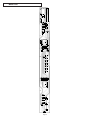
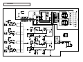
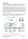
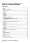
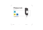
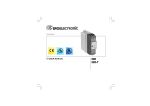
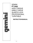
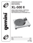
SERVICE MANUAL
BPM-1
PROFESSIONAL AUTOMATIC BEAT COUNTER
CONTENT’S:
Connections & Operations:.......................................................Page 2-3
Specifications:..............................................................................Page 3
Parts Lists:.................................................................................Page 3-4
PCBs:..........................................................................................Page 5-6
Schematics:..................................................................................Page 7
Gemini Sound Products Corp.
120 Clover Place P.O. Box 6928
Edison, NJ 08818-6928
732-738-9003 (Phone) • 732-738-9006 (Fax)
Page 1
Page 2
13
14
15
5
4
2
1
3
5
4
2
1
16
6
7
7
8
8
17
9
10
10
11
11
18
12
19
20
21
Connections
1. Make sure that the POWER (13) switch is in the off position. The
POWER LED (14) will be off. This unit comes supplied with a 15 volt
AC adaptor. Plug the adaptor into the rear panel power jack. Then plug
the adaptor into a proper power source.
2. Use the 4 stereo PHONO/LINE (2, 5, 8, 11) inputs on the rear panel to
connect to the output of your sources. The PH1/LN1 (12) switch
enables you to set the CHANNEL 1 (11) input sensitivity to Phono or
Line. The PH2/LN2 (9) switch enables you to set the CHANNEL 2 (8)
input sensitivity to Phono or Line. The PH3/LN3 (6) switch enables you
to set the CHANNEL 3 (5) input sensitivity to Phono or Line. The PH4/
LN4 (3) switch enables you to set the CHANNEL 4 (2) input sensitivity
to Phono or Line. Note: When using turntables, don’t forget to connect
the ground wire from your tuntable to the ground screw of your mixer.
3. The BPM-1 is supplied with 4 sets of OUTPUT (1, 4, 7, 10) jacks. If you
are using a turntable and have the input set to phono, the
corresponding output must be connected to phono inputs on your
mixer. If you have the input set to line, the corresponding output must
be connected to line inputs on your mixer. Use the CHANNEL 1
OUTPUT (10) jacks to connect to the appropriate inputs on your mixer.
Use the CHANNEL 2 OUTPUT (7) jacks to connect to the appropriate
inputs on your mixer. Use the CHANNEL 3 OUTPUT (4) jacks to
connect to the appropriate inputs on your mixer. Use the CHANNEL 4
OUTPUT (1) jacks to connect to the appropriate inputs on your mixer.
NO
TE
NOTE
TE: Beat mixing is a skill that requires practice. Not
every track has a strong beat, and beat mixing works best
with tracks that have clear and strong beats.
Specifications
INPUTS:
Phono......................................................................................3 mV 3 MOhm
Line.....................................................................................150 mV 3 MOhm
OUTPUTS:
Input/Output Resistance..................................................................<0.1 Ohm
GENERAL:
BPM Range.............................................................................60 - 180 BPM
Power Adapter...........................................................115V/15V AC 500 mA
230V/15V AC 500 mA
Dimensions......................................19”w x 1.75”h x 3”d (483 x 44 x 78 mm)
Weight.....................................................................................3 lbs (1.5 kg)
Parts Lists
Cabinet Parts and Packing
Item #
Operation
1. POWER ON: Once you have made all the equipment connections, press
POWER (13). The power will turn on and the POWER LED (14) will
glow RED. When you turn on the BPM-1, the unit will run through an
initialization period in which the BPM DISPLAYS (17, 19) and the BEAT
OFFSET INDICATORS (18) will flash. When the flashing stops, the unit
is ready for use.
2. The ASSIGN (16, 21) buttons allow you to select which channel will be
displayed on each side of the BPM-1. Press the ASSIGN (16) button to
select channel 1, 2, 3 or 4 to be displayed on the left BPM DISPLAY
(17). The ASSIGN LED (15) will indicate the channel you selected.
Press the ASSIGN (21) button to select channel 1, 2, 3 or 4 to be
displayed on the right BPM DISPLAY (19). The ASSIGN LED (20) will
indicate the channel you selected.
3. BPM DISPLAY: There are BPM DISPLAYS (17, 19) for each side of the
BPM-1. They update approximately every 2.5 seconds and digitally
display the Beats Per Minute allowing you to match the beats visually.
BPM DISPLAY (17) reflects the Beats Per Minute of the channel
assigned to the left side of the unit, and BPM DISPLAY (19) reflects
the Beats Per Minute of the channel assigned to the right side of the
unit.
NO
TE
NOTE
TE: A [- -] reading will appear on the BPM DISPLAY if the
track has unclear beats. The [- -] reading will also appear if
there is no signal present.
4. The BEAT OFFSET INDICATORS (18) light when the tracks of the two
channels assigned to the crossfader are within 11 BPMs of each other
and display how aligned the beats of the two channels are. When the
RED LEDs light, the beats are not aligned. When the YELLOW LEDs
light, the beats are almost aligned. When the GREEN LED lights, the
beats are aligned perfectly.
NO
TE
NOTE
TE: If the difference between the two channel’s beats
exceed 11 BPM, the BEAT OFFSET INDICATORS will not
light.
SUGGESTION: You can use the BPM DISPLAYS to determine which
tracks have similar or the same Beats Per Minute. When mixing two tracks
with similar Beats Per Minute, you can use one source’s pitch control to
align the Beats Per Minute with the other source’s BPM. The BPM
DISPLAYS and the BEAT OFFSET INDICATORS update every 2.5
seconds and will reflect the change in BPM and indicate when the beats
are aligned.
Page 3
1
2
3
4
5
6
7
8
9
10
11
12
13
14
15
Description
CASE
CHASSIS
KNOB PUSH
HOLDER LED (3ø 6.5mm)
PLATE DISPLAY (SMALL)
CLIP WIRE
SERIAL NO. LABEL
GIFT BOX
OWNER’S MANUAL
BAND-HEAD TAPPING SCREW (TWIN)
BAND-HEAD TAPPING SCREW/TW-E
BAND-HEAD TAPPING SCREW (TWIN)
BAND-HEAD TAPPING SCREW ( “NUT” )
BAND-HEAD TAPPING SCREW
NUT/WASHER
Part #
031-032
021-461
002-571
003-732
003-372
049-190
196-061
255-131
157-962
110-166
121-003A
110-172A
111-044A
111-046A
131-057
Printed Circuit Boards
Item #
1
2
Description
PRINTED CIRCUIT BOARD BPM1-1
PRINTED CIRCUIT BOARD BPM1-2
Part #
262-239
262-240
Parts Lists - Meter PCB
ICs
Item #
1
2
Designators
IC5
IC1
Description
INTEGRATED CIRCUIT M66313FP
INTEGRATED CIRCUIT SC87C51CCN40
Part #
074-155
074-157
Electrical Parts
Item #
Designators
1
2
A, B
D1-2, D6-7,
D20-27, D30
D3, D5
D4
SWA, SWB
XT1
3
4
5
6
Description
Part #
LED NUMERIC DISPLAY
LIGHT EMITTING DIODE (RED) 3ø
080-102
080-003
LIGHT EMITTING DIODE (YELLOW) 3ø
LED (GREEN) 3ø
TACT SWITCH
CERAMIC RESONATOR 12 MHz
080-062
080-063
082-041
052-018
Parts Lists - Main PCB
ICs
Item #
1
2
Designators
Description
IC2, IC3, IC4, IC8 INTEGRATED CIRCUIT UPC324
IC7
INTEGRATED CIRCUIT NJM7805FA
Part #
074-011
074-074
Electrical Parts
Item #
1
2
3
4
Designators
D18
D8-10, D12-14
J1-4
SW1-4
Description
RECTIFIER DIODE 1N4002 (1N4003,1N4004)
SILICON DIODE 1N4148
4P RCA JACK
SLIDE SWITCH 2P2C PH/LN
Page 4
Part #
079-027
079-003
161-169
081-027
Main PCB
Page 5
Meter PCB
Page 6
Schematic
SWA
VCC
SWA
VCC
IC1
C100
VCC
VCC
SWB
SWB
D30
LED
C101
104
104
LED4A
LED3A
LED2A
LED1A
LED1B
LED2B
LED3B
LED4B
1
2
3
4
5
6
7
8
CH B
CH A
13
12
R121
750
15
14
C9
47pF
B3
A3
B4
A4
VCC
METER PCB
19
18
1
B2
2
A2
1
B1
2
A1
31
VCC
XT1
12M
C10
47pF
X3
9
VCC
X11
1
X12
C11
10/10
X2
MAIN PCB
SW1A
17
16
P10
P11
P12
P13
P14
P15
P16
P17
P00
P01
P02
P03
P04
P05
P06
P07
INT1
INT0
P20
P21
P22
P23
P24
P25
P26
P27
T1
T0
EA/VP
39
38
37
36
35
34
33
32
A4
B4
A3
B3
B2
A2
B1
A1
IC5
VCC
12
21
22
23
24
25
26
27
28
SWA
P21
P22
P23
P24
P25
P26
P27
11
LE
X1
X2
RESET
9
10
11
30
29
RXD
TXD
ALE/P
PSEN
RD
WR
A
SWB
13
CK
8051
R1
L2
R2
R3
L3
R4
L4
R1
10K
1
2
X6
3
X5
L1
1
3
2
2
C32
VCC
563
10
4
SW1B
C39
5
CH1
240
OE
C28
R97
6
47/10
J1B
SD
1L
R90
SQ32
682
R82
R81
J1A
2L
300K
R98
100K
300K
R100
100K
L1
2
3
4
5
6
7
42
41
40
39
38
37
36
35
34
33
31
30
29
28
27
26
25
24
23
22
15
16
17
18
19
20
13
R72
b2b
b2f
R69
470
470
b2a
b2g
b3c
b3b
b3f
b3a
b3g
a2f
a2b
a3b
a3f
a3a
a3g
a2a
a2g
a3d
a3e
a3c
470
R73
470
R78
470
R65
470
R62
470
R59
470
R52
470
R57
470
R51
470
R56
470
R58
470
R76
470
R54
470
R55
470
R53
470
a1b.1c
a2d
a2e
a2c
b3e
b3d
b1b,1c
b2d
b2e
b2c
470
R80
240
470
R74
470
R79
240
R71
470
7
470
R60
470
R64
470
R68
470
R67
2b
3f
1
6
1G
D20
LED1A
2e
1c
2c
3e
LED
D21
LED2A
LED
3c
2d
LED
D2
P26
LED
3d
D3
D22
LED3A
P25
LED
VCC
10
12
11
15
4
5
3
LED
D4
D23
LED4A
P24
30
25
31
26
19
24
18
LED
LED
D5
D24
LED1B
P23
B
BT-A41
3a
3b
3g
2a
2f
1b
2b
3f
2c
3e
2g
LED
LED
D6
D25
LED2B
P22
2e
1c
VCC
23
3c
2d
3d
LED
M66313FP
LED
D7
IC8C
2G
R119
510
R10
510
A
BT-A41
3a
3b
3g
2g
470
14
2
2a
2f
1b
15
11
12
10
22
21
32
28
29
27
R77
R61
9
D1
25
30
20
19
24
18
23
14
9
2
7
1
6
8
13
4
5
3
470
R75
470
R63
14
P27
R66
R70
8
26
31
4
3M3
Q1
Q2
Q3
Q4
Q5
Q6
Q7
Q8
Q9
Q10
Q11
Q12
Q13
Q14
Q15
Q16
Q17
Q18
Q19
Q20
Q21
Q22
Q23
Q24
Q25
Q26
Q27
Q28
Q29
Q30
Q31
Q32
D26
LED3B
P21
9
8
2R
1R
1/2VCC
R89
LED
10
27
29
28
32
21
22
LED
20
OA4
3M3
11
R99
R1
100K
D27
R101
LED4B
C1
100K
LED
332
R114
C13
104
100K
R23
680K
C20
R21
91K
IC2A
C54
2
3
1
4.7/25
CH2
SW2B
C41
5
9.1K
C29
R116
R19
LM324A
1/2VCC
47/10
J2A
1L
10
1N4148
R25
68K
104
LM324A
R14
R27
1K
6.8K
LM324A
R92
R83
682
R84
300K
300K
R102
100K
C2
47/6.3
R30
22K
R104
100K
L2
VCC
4
3M3
IC8D
1G
VCC
13
14
R33
470K
R35
1M
OA4
11
R103
R2
100K
R105
11
3M3
C26
Vcc
100K
IC3B
471
IC2D
LM324AD10
14
13
D9
B
C15
6
3
A
D11
11
POWER
11
SW3A
R37
100K
2
C22
4.7/10
R41
330K
C24
2.2/16
R38
100K
X7
3
C42
5
240
C56
R94
R85
682
R86
300K
300K
X4
R106
100K
R108
100K
L3
332
R115
4
3M3
IC8A
2
1G
2R
1R
1/2VCC
R93
Vcc
4
1
3
R
C55
IC4A
2
OA4
3M3
11
R107
R3
4.7/25
1/2VCC
3
R20
9.1K
100K
LM324A
181
C16
LM324A
104
R16
1K
1/2VCC
D12
8
C18
7
10
1N4148
5
104
1
R18
R28
1K
6.8K
2
R34
470K
CH4
240
J4A
2L
1L
R96
11
C27
R87
682
R88
300K
300K
471
R110
100K
R112
100K
L4
IC4D
13
R95
1/2VCC
5
R111
100K
R4
14
13
Vcc
104
LM324A
LM324A
LM324A
R39
100K
OA4
3M3
11
1R
R5
10K
12
R48
5K1
11
1N4148
6
A
D15
8
1N4148
1N4148
7
2R
9
10
12
IC8B
1G
B
C19
D14
14
D13
4
3M3
2G
IC3D
IC3C
4
6
47/10
J4B
R36
1M
C31
R118
4
C43
5
4
SW4B
11
4
C23
4.7/10
R43
330K
1
1
C8
104
Vin
Vout
3
C36
1.0/10
R8
10K
1/2VCC
C3
47/6.3
3
563
7805
VCC
1
C38
470/25
LM324A
R26
68K
SW4A
C33
IC7
2
POWER
IC4C
9
IC4B
6
X1
D18
2
1N4004
R31
22K
11
11
100K
1
R109
J10
R24
680K
C21
R22
91K
4
2G
C17
104
100K
2
47/10
1L
X8
C30
R117
6
J3A
2L
4
CH3
J3B
11
4
SW3B
C5
104
SW5
LM324A
LM324A
104
C4
104
2
1N4148
1N4148
R2
10K
C6
104
1
7
5
12
1N4148
1
C7
104
IC3A
4
1R
12
4
2R
1/2VCC
R91
4
2G
GND
2L
D8
8
C14
7
5
6
J2B
9
IC2B
6
104
R12
1K
IC2C
181
C12
11
240
3
11
4
1/2VCC
11
L
2
4
SW2A
4
4
Vcc
1
R29
22K
R40
100K
C25
2.2/16
A
R113
R6
6K2
100K
B
R46
1K1
R32
22K
R9
6K2
C40
470/10
R120
510
In the USA: If you experience problems with this unit,
call 1-732-738-9003 for Gemini Customer Service.
Do not attempt to return this equipment to your dealer.
Parts of the design of this product may be protected by worldwide patents.
Information in this manual is subject to change without notice and does
not represent a commitment on the part of the vendor. Gemini Sound
Products Corp. shall not be liable for any loss or damage whatsoever
arising from the use of information or any error contained in this manual.
No part of this manual may be reproduced, stored in a retrieval system or
transmitted, in any form or by any means, electronic, electrical, mechanical,
optical, chemical, including photocopying and recording, for any purpose
without the express written permission of Gemini Sound Products Corp.
It is recommended that all maintenance and service on this product is
performed by Gemini Sound Products Corp. or its authorized agents.
Gemini Sound Products Corp. will not accept liability for loss or damage
caused by maintenance or repair performed by unauthorized personnel.
Worldwide Headquarters • 120 Clover Place, Edison, NJ 08837 • USA
Tel: (732) 738-9003 • Fax: (732) 738-9006
France • G.S.L. France • 11, Avenue Leon Harmel, Z.I. Antony, 92160 Antony, France
Tel: + 33 (0) 1 55 59 04 70 • Fax: + 33 (0) 1 55 59 04 80
Germany • Gemini Sound Products GmbH • Ottostrasse 6, 85757 Karlsfeld, Germany
Tel: 08131 - 39171-0 • Fax: 08131 - 39171-9
UK • Gemini Sound Products • Unit C4 Hazleton Industrial Estate, Waterlooville, UK P08 9JU
Tel: 087 087 00880 • Fax: 087 087 00990
Spain • Gemini Sound Products S.A. • Rosello, 516, Barcelona, Spain, 08026
Tel: 349-3435-0814 • Fax: 3493-347-6961
© Gemini Sound Products Corp. 2002
All Rights Reserved