1
SubSeries 6i,
SubSeries 5 i,
SubSeries 1,
Powered Subwoofers
OWNER'S GUIDE
I. IMPORTANT SAFETY INSTRUCTIONS
II. INTRODUCTION
III. QUICKSTART
IV. FEATURES, CONTROLS, AC POWER
A. Sub Volume Control (Figure 1)
B. On Indicator Light (Figure 1)
C. AC Power Connection
D. Sub Cut-Off Frequency Control (Figure 1)
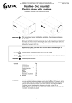
E. High/Speaker Level Terminals (Figure 2)
F. AC Power Socket (Figure 2)
G. External Fuse (Figure 2)
H. Low/Line Level Jacks (Figure 2)
I.
Phase Switch (Figure 2)
J. LFE Input/Crossover Bypass Switch (Figure 2)
K. Power Switch (Figure 2)
L. Amplifier Panel (Figure 2)
V. ROOM ACOUSTICS, SUBWOOFER PLACEMENT, MULTIPLE SUBWOOFERS &
SETTING THE CONTROLS
VI. CONNECTING THE SUBWOOFER TO YOUR AUDIO SYSTEM
A. The SubSeries 1
B. The SubSeries 5 i
C. The SubSeries 6i
D. Using Multiple Subwoofers
VII. SET-UP CALIBRATION
VIII. SPECIFICATIONS
w w.psbspeake~.com·
Ph.,,: (888) 772-00oo.r (905) 831-8555
IE
I.
IMPORTANT SAFETY INSTRUCTIONS
1.
2.
3.
4.
5.
6.
7.
8.
Read these instructions.
Keep these instructions.
Heed all warnings.
Follow all instructions.
Do not use this apparatus near water.
Clean only with dry cloth.
Do not block any ventilation openings. Install in accordance with the manufacturer's instructions.
Do not install near any heat sources such as radiators, heat registers, stoves, or other apparatus
(including amplifiers) that produce heat.
Do not defeat the safety purpose of the polarized or grounding-type plug. A polarized plug has two
blades with one wider than the other. A grounding type plug has two blades and a third grounding
prong. The wide blade or the third prong are provided for your safety. If the provided plug does not
fit into your outlet, consult an electrician for replacement of the obsolete outlet.
Protect the power cord from being walked on or pinched particularly at plugs, convenience receptacles, and the point where they exit from the apparatus.
Only use attachments/accessories specified by the manufacturer.
Use only with the cart, stand, tripod, bracket, or table specified by the manufacturer, or sold with the
apparatus. When a cart is used use caution when moving the cart/apparatus combination to avoid
injury from tip-over.
Unplug this apparatus during lightning storms or when unused for long periods of time.
Refer all servicing to qualified service personnel. Servicing is required when the apparatus has been
damaged in any way, such as power-supply cord or plug is damaged, liquid has been spilled or
objects have fallen into the apparatus, the apparatus has been exposed to rain or moisture, does not
operate normally, or has been dropped.
WARNING: To reduce the risk of fire or electric shock, this apparatus should not be exposed to rain
or moisture and objects filled with liquids, such as vases, should not be placed on this apparatus.
To completely disconnect this equipment from the mains, disconnect the power supply cord plug
from the receptacle.
The mains plug of the power supply cord shall remain readily operable.
9.
10.
11.
12.
13.
14.
15.
16.
17.
The lightning flash with arrowhead symbol within an equilateral triangle, is intended to
alert the user to the presence of uninsulated "dangerous voltage" within the product's
enclosure that may be of sufficient magnitude to constitute a risk of electric shock to
persons.
The exclamation point within an equilateral triangle is intended to alert the user to the
presence of important operating and maintenance (servicing) instructions in the literature accompanying the product.
Notes on environmental protection
At the end of its useful life, this product must not be disposed of with regular household waste but must be returned to acollection point for the recycling of electrical and
electronic equipment. The symbol on the product, user's manual and packaging, point
this out.
The materials can be reused in accordance with their markings. Through re-use, recycling of raw materials, or other forms of recycling of old products, you are making an
important contribution to the protection of our environment.
Your local administrative office can advise you of the responsible waste disposal point.
3
II.
INTRODUCTION
PSB subwoofers are designed to provide the flattest possible frequency
response, full bass extension, low distortion and high output. Frankly, these are
characteristics that most manufacturers would strive for. Our years of experience and our sophisticated design and measurement tools allow us to achieve
ideal subwoofer performance. Beyond these characteristics there are afew other
parameters that we uniquely feel are very important in the design of asubwoofer. First and foremost it is important to us that a PSB subwoofer be musical. In this era of home theater this might at first seem out of step, but we
believe that amusical subwoofer will also sound the most natural when playing
movie soundtracks. Furthermore, an ideal subwoofer should have the ability to
play musically even under conditions of overload or stress. No subwoofer is so
large with its limits so great that it can never be overloaded, especially with
modern movie soundtracks. For this reason PSB subwoofers incorporate very
intelligently applied proprietary limiting circuitry to prevent audible overload.
The limiting circuitry of all PSB subwoofers is acombination of peak limiting
circuits that hold amplifier signal swing to the point just short of the amplifiers
clipping, and compression circuitry that will come in under conditions of long
term overload and reduce the amplifiers gain. The trick is to apply these circuits
in such away that they don't squeeze the life out of the music or movie soundtrack, to allow the dynamics to get through while preventing gross distortion.
We do this by being mindful of the dynamics of music and carefully tailoring the
time constants of the circuits to that of music. For example, it is known that
most music is performed with abeat of 80 to 140 beats per minute. Our test
signals are configured to follow this timing and allow maximum transient effect
without distortion on sustained tones.
We go to great lengths to reduce any mechanical noises our subwoofers may
make. Woofers are designed never to bottom harshly. Ports have large radius
end flares to reduce noise from turbulence. Cabinets and amplifiers are designed
so that no air leaks (which can contribute minute amounts of noise) are possible. All of our designs are exhaustively tested. Asubwoofers design isn't complete until the sub's amp and woofer can survive a15 hour test of being driven
continuously to maximum output.
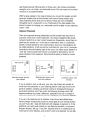
SubSeries 1
The SubSeries 1 has afew unique features worth mentioning. We have mounted
Volume and Crossover controls on the front of the cabinet. Most subwoofers are
tucked away in adark corner and once in place it can be very inconvenient to
access the controls. Placing volume and crossover knobs on the front of the
cabinet will allow you to adjust these most important functions more conveniently. Despite its modest price the SubSeries 1contains asimplified version of
our two part limiting circuit and a100 watt class AB amplifier.
4
SubSeries 5i
The SubSeries 5i has more power and a larger bass unit than the SubSeries 1. It
also has a very different Class H design for its power amplification. Class H is a
special high efficiency amplifier design. Briefly, audio amplifiers are inherently
inefficient because they are designed to have the capability of delivering great
output power yet spend most of their life delivering fairly low power. Their output devices must deliver current while withstanding the high power supply "rail"
voltages needed for peak outputs. With a Class H design the rail voltages are not
constant. They swing high when the music demands it and stay low during quiet
passages. This is achieved by a sophisticated high frequency switching power
supply. Power dissipated as heat is greatly reduced and more power is available
per dollar of cost ·A second benefit is that they tend to have high peak power
relative to their steady state power. The SubSeries 5i, for example, has 150
watts continuous but is capable of 450 watt peaks. The result is a subwoofer
capable of the great transients required by dynamic music and explosive sound
effects.
SubSeries 6i
The SubSeries 6i has a design much like the 5i but with larger drive units and
greater power for even more awesome output. In the words of our engineering
staff it "Cranks pretty good."
Additional features of the 6i are its high and low level passive and active filtering
circuits that allow greater flexibility in installation.
Whichever PSB subwoofer you have chosen, we hope that you appreciate the
attention to detail that has gone into its design and, of course, that you enjoy
using it. Please take the time to read the following sections about the placement
of your subwoofer, and its connections and adjustments.
We suggest you save the original carton and packing materials, at least for an initial period. Should you ever need to ship or store your PSB subwoofer, it is the
best packaging in which to do so.
III.
QUICKSTART
If you cannot wait to hear your new PSB subwoofer: Turn off all other components, and follow one of the connection diagrams. Connect the supplied power
cord to the AC power socket. Set the PSB subwoofer volume control to its minimum position (counterclockwi$e), then plug the subwoofer into an active AC
outlet. The same receptacle as the rest of your audio/video system or another
on the same electrical circuit should be used to avoid ground hum. Set the subwoofer's Sub Cut-Off Frequency control to its midpoint, and the phase switch to
0°. Flip the Power Switch to the on position. Playa bass-rich program source,
and slowly bring up the Sub Volume control (clockwise) until the subwoofer
contributes a natural level of low frequency sound. Now please read the rest of
this guide and fine-tune your installation accordingly-it will be time well spent!
5
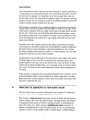
IV.
FEATURES, CONTROLS, AC POWER
A. SUB VOLUME CONTROL
D. SUB CUT-OFF FREQUENCY - - - - ,
CONTROL
Adjusts the output level of the
PSB subwoofer only: This is
not intended as a day-to-day
volume control. See "VII. Setup
Calibration"
The PSB subwoofer includes
designed-in dynamic-range
protection: IT is virtually impossible
to overdrive the subwoofer,
regardless of volume setting or the
demands of the program material.
Where even higher levels of low
frequencies are required, a second
PSB subwoofer can provide a
significant gain in total bass levels.
Adjusts the high-frequency roll-off of
signals sent to the subwoofer.
Continuously variable from 50Hz to
150Hz for precise matching of
subwoofer bass reproduction WITh the
main (left and right) stereo speakers.
See "VII. Setup Calibration"
VOlUME
o
'------f-- 0
o
rJ
00
CIIOSSOVII
0
100DlOO
0
0
0
0
0
0
0
010
500
0
~_~
0
0150
Figure 1
(located on the front
of tile subwoofer)
B. ON INDICATOR LIGHT
The light is located between the
control knobs. WITh both the 120
and 230 vo~ versions, the
subwoofer is initially in stand-by
mode awaITing the presence of an
audio signal. When the subwoofer
receives an audio signal the On
indicator will illuminate. At the end
of the audio signal the subwoofer
will stay on for approximately 15
minutes.
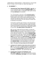
C.
E.
HIGH/SPEAKE
LEVEL TERMINALS
Connect the PSB subwoofer to
receivers or integrated amplifiers
equipped with speaker outputs
only. See "VI. Connecting The
Subwoofer to Your Audio
System".
F.
AC POWER SOCKET
Supplies AC power to the PSB
subwoofer Connect the supplied power
cord to the AC power socket. Plug the
power cord into any standard wall
outlet. With 230 vo~ versions, in some
countries it may be necessary to
replace the power cord to meet the
standards in use locally.The same
receptacle as the rest of the system or
another on the same electrical cirCUIT
should be used to avoid ground hum.
AC POWER CONNECTION
The PSB subwoofer has its own self-contained amplifier and thus requires AC power (keep this in mind
when selecting a location). You may plug the power cord into any standard wall outlet and leave the
connection in the wall as the PSB subwoofer draws extremely little current when idle. You may want to
unplug your PSB subwoofer when it will not be used for an extended period such as a vacation.
6
. - - - - - - - - - - - - - I.
@
-
Uti.....
.
_
..... ........
.......
.-LMI.
..
9
It
-
LM ....
_
~
+€) @+
,...
9r
It
+@ @+
---
PHASE SWITCH
Selects the subwoofer output phase
between in-phase (DC) and out-of-phase
(180 e ), to compensate for the low to
mid bass acoustic effects of different
placement locations and listening
rooms, See "VII Setup Calibration"
Ii)
@
Ell
(f)
Ell
$
It
..
®
"-----+--J.
$
$
... ..
....
-@ @- --@ @- _LMl
... ........
....
...-
@
Connect the PSB subwoofer to a
separate-component preamplifier, or to
an integrated amplifier or receiver with
preamplifier-ouVmain-in facilities, at
line level See "VI Connecting The
Subwoofer to Your Audio System",
@
_......
~-.=..
LOW/LINE LEVEL JACKS
_-
K.
When active, the subwoofer variable low
pass fitter is bypassed so that this
function can be accomplished by the low
pass fitter within a receiver/processor. See
"VII, Setup Calibration",
.....
..--,-----._
11------..
1ntIIa..-
_
__
LFE INPUT/CROSSOVER BYPASS
SWITCH
Figure 2
SubSeries 6i back plate
used lor Illustration
L.
G. POWER SWITCH
The Power Switch turns the PSB
subwoofer on and off, As the
subwoofer draws only an extremely
small current when idle, this may be
left normally on and turned off only
when you do not expect to use the
subwoofer for an extended period, The
Power Swrtch must be in the on
position for normal operation,
H.
AMPLIFIER PANEL
The metal provides cooling for the
PSB subwoofer's internal amplifier
by radiating heat produced in normal
operation, Allow air circulation,
including at least four inches
clearance from wall or furnishings
7
EXTERNAL FUSE
When you turn on the subwoofer and
there is no LED light and/or sound,
please check the fuse (accessible
from the rear panel) to ensure it is
electrically intact The fuse could have
become broken during transit. Aspare
fuse is contained within the fuse
holder compartment behind the
inscribed text, Use a wide slot
screwdriver to pry the fuse holder
compartment from the AC power
socket If it is necessary to replace
the fuse, use a fuse equivalent to the
type and rating of the fuse shipped
with the product See the
specifications page at the end of the
manual for a detail description of the
fuse required for your model of
subwoofer,
V.
ROOM ACOUSTICS, SUBWOOFER PLACEMENT, MULTIPLE SUBWOOFERS &
CONTROL SETTINGS
Room Acoustics
If you are critical about low-frequency response, there's quite a bit of useful
experimentation you can do, especially in combination with the crossover, level,
and phase controls of our subwoofers.
Since the earliest days of high fidelity, one of the main challenges for the
designers of speakers, and of their users, has been management of the lowest
frequencies-the deep bass. Many of the most notable developments in speaker
design have been made with a view to getting more bass output from smaller
boxes.
One consideration is the size of the listening room. The larger the volume of air
a speaker must excite, the more acoustic output you will require from it to
achieve the sound levels you want. In any environment, sounds attenuate as you
move farther away from their source, but in smaller rooms that tends to be offset by reinforcement from wall reflections. The larger the space is, the farther
the sound has to travel both to reach the reflecting surfaces and then to get to
your ears, which means it has to be louder to begin with.
With traditional full-range speakers, that involves an intricate matching act
between amplifier power, speaker sensitivity, impedance and power handling.
But the bulk of the power goes to reproducing bass, so the use of powered subwoofers and separate midrange/treble satellites both allows you to be conservative in the amount of power your main amplifier produces, and ensures a good
match between the low-frequency amplifier and the woofer it is paired with.
After size, the most important aspect of a listening room is its shape. In any
room, sound reflects off the walls, ceiling, and floor. If the distance between two
opposite parallel surfaces is a simple fraction of the wavelength of a particular
frequency, notes of that frequency will bounce back and forth in perfect phasean effect called a standing wave or room mode.
At some point in the room, this note will be reinforced substantially; at others it
will cancel out almost entirely. If the prime listening seat is placed at either of
these locations, the note will be a horrible boom or virtually non-existent. The
standing waves are different between floor and ceiling, side walls, and end walls,
unless any of these dimensions are the same. An ideal listening room would
have no parallel surfaces-an unusual situation, to say the least-so that such
waves would not establish themselves. The worst kind of room is a perfect
cube.
Almost all rooms are susceptible to some standing waves at low frequencies,
but their effects can be minimized by careful positioning of both the speakers
8
and the listening seat. Moving either of these even a few inches is sometimes
enough to cure-or create-an intolerable sound. The only way to find out what
works best is by experimentation.
With full-range speakers, the range of places you can put the speakers and still
get proper imaging may be fairly limited, and some of these positions may
result in standing waves that can't be tamed. Things are more controllable
through the use of a subwoofer or two. Positioning of the bass speakers has
almost no impact on imaging, so a subwoofer can be located with only standing
waves in mind.
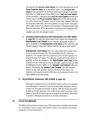
Subwoofer Placement
There is no argument among audiophiles that the loudest bass output from a
subwoofer comes from corner placement. The natural megaphone-like flaring
outward of walls from a room corner focuses low frequencies-giving them no
place to go but toward you. In the case of subwoofers, there is no automatic
penalty in overall balance for this maximal bass, since your main speakers can
be located elsewhere. It still may be too much bass for your room or (more particularly) your favorite listening spot in the room, but unless you are seated in a
"null" spot, where sound from the sub is cancelled or diminished by out-ofphase reflections from elsewhere, there should be plenty of bass from corner
placement.
PSB subwoofer ---+
[8
~
t:fJ
fEj
l.....Ud
Most bass output; least even
bass response.
[:l]
PSB
S_Ub_WOOfer :
~I
J
Moderate bass output; more
even bass response.
PSB
subwoofer
c:o
Lowest bass output; most
even bass.
If you are seated in such a null spot, your only real choices are generally to
move either the subwoofer or your listening position until bass returns to the
point that satisfies. Cranking up the level control or changing the crossover
point almost certainly won't help much. But flipping the phase control 180
degrees sometimes may make a difference, especially if the null is a product of
cancellations caused by interaction with low frequencies from your main speakers.
If you are in the opposite sort of situation, where direct and reflected bass
waves converge in phase and produce a strong peak at your listening location,
you can-if you like-deal with that both with changes in placement or in the
position of your sub's level control (or, less likely but possible, the crossover
frequency chosen). We say "if you like" because there is no such thing as too
much bass for some listeners, and we don't want to be dogmatic. You are defi9
nitely the one who has to be pleased, unless your Significant Other chimes in to
the contrary.
As you go outward from the corner along one wall or another, the general consensus (with which we tend to agree) is that while bass output diminishes
somewhat, it also becomes more uniform throughout the room, with fewer of
the "standing waves" that produce peaks and nulls at various points.
Chances are things won't be so simple, so the best method for positioning a
subwoofer, although a rather undignified-looking one, is to put the subwoofer in
your listening chair, then play music with lots of bass through the system something with steady low frequencies (such as organ music) or continuous test
tones, not movie material. Move around the room and note where the bass
sounds best; if you place the subwoofer there and yourself in your chair, you
should get the same bass performance. Bear in mind that the test only works if
you have your ears as high off the floor as the subwoofer will be, so don't be
afraid to crawl around. A recommended starting point for the placement of this
subwoofer would be in either of the front corners of the room (on either side of
the main speakers).
Multiple Subwoofers-Why Two Subs Are Better Than One
Since the objective of most people who buy subs is to make sure of plentiful
low frequencies, the only situation most of us will run into that makes subwoofer placement really difficult is the factor we all fear-the "bad" room that
just won't let you get satisfying amounts or quality of bass. There are rooms
with troublesome dimensions, especially as you approach a perfect cube (with a
closed door). There is unlikely to be any combination of speaker and listener
position that will be free of obvious acoustic anomalies.
In such a case, the best way to iron out those anomalies is with two subwoofers, placed carefully to work with each other. This can also be true when
the problem is too much, or too uneven, bass. The overall system needs all the
help it can get, and that often means the use of two subwoofers, each one of
which corrects for the acoustic problems excited by the other. For excellent
results from this solution, the two subs don't have to be identical. It may be
fine, in fact, to use two lesser subs to equal the performance of one with
stronger specs.
Recent studies have shown that an excellent way to position two subwoofers is
with each in the center of opposite walls. That is, with one in the center of the
front wall and a second in the center of the back. Alternatively, try one in the
center of each side wall.
The same "crawl around the room" method as previously described should be
used for determining the location of the second subwoofer, except in this
instance one is listening for the minimum amount of bass output. This is a recommended starting point for determining the best placement for your subwoofer(s).
10
Control Settings
Once a reasonably smooth response has been achieved by careful positioning of
the subwoofers, the overall performance can be fine-tuned by means of the controls found on the speaker. An important one is the low-pass filter, which controls the upper limit of the subwoofer's frequency range. This should be set high
enough to overlap the low frequency cutoff of the satellite speakers, but not high
enough to localize specific sounds from the sub.
If the frequency response of your satellite speakers is such that the subwoofer's
low-pass filter must be set higher than about 80Hz in order to avoid gaps in the
overall system response, then you might well be able to localize specific sounds
from the sub. This can be very distracting when these sounds appear to come
from beside or behind you. One solution is to make sure the subwoofer is in the
front of the listening area; another is to use multiple subwoofers to make such
sounds more diffuse.
Subwoofers also offer a phase control so the upper frequencies they produce
will not cancel out the lower frequencies of the satellites. A judicious tweaking of
this control can pay major dividends in spectral smoothness in the crossover
area. Phase changes with frequency, however, so these controls may need readjusting every time you vary the cutoff frequency.
Also adjustable is the overall level of the subwoofer's output. Many users tend to
set this too high at first, in an effort to achieve truly impressive bass. Again,
smooth response is the aim, and it may well be that, if you use them, two subwoofers end up being set differently-if, for example, one is in a corner and the
other is not. It's all part of the overall-balancing act that is bass management in
real rooms.
We get virtually no inquiries about subwoofer placement from customers, which
is a good indication that it's not something over which people lose much sleep.
A good subwoofer is such a pleasure when used with a good main speaker that
enjoyment is definitely the rule.
VI.
CONNECTING THE SUBWOOFER TO YOUR AUDIO SYSTEM
There are several ways to connect a subwoofer into a system. For best results
overall, we recommend using Low/line Level connections.
When making a Low/line Level connection, be sure to follow the coding on the
cables to maintain left-to-Ieft and right-to-right. Use high quality, well-shielded,
low capacitance RCA cables of minimal necessary length, to avoid picking up
noise in the cable runs. When making a High/Speaker Level connection, in
addition to maintaining left-to-left and right-to-right, be sure to use the coding
of the pair of wires in each speaker cable to maintain phase-+/red/rib/writing to
11
tired/rib/writing and -/white/smooth/clear to -/white/smooth/clear. We recommend
minimum 16 gauge wire and, for longer runs, larger (lower gauge) wire.
A.
THE SUBSERIESTM 1
1.
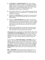
Connecting Home Theater Equipment (SEE FIGURE 3, page 16): You
can use a single RCA cable to connect the Subwoofer Output of your
receiver, integrated amplifier, or preamplifier to either right or left side
of the Low Level Input on the subwoofer.
Home Theater receivers, integrated amplifiers, surround sound processors, and preamplifiers usually have a special Subwoofer Output to
provide the optional (Dolby Digital 5.1) Low Frequency Effects (LFE)
Channel present on many movie and other programming sources. To
reproduce these deep-bass effects (when they are present), supplementing the bass information in the main channels, this output must
be connected to the subwoofer.
The subwoofer output/LFE signal is filtered by most receivers/processors. The subwoofer's variable low pass filter is usually not required
and should be bypassed by switching the LFE Input/Crossover bypass
switch to active only if the receiver/processor subwoofer/LFE output is
low pass filtered. The default position for this switch is off.
With some Home Theater electronics and settings, connecting the
Subwoofer Output does not provide the low frequencies from normal
stereo music through the subwoofer. If this is true of your system,
you can make two connections. First, connect the Subwoofer Output
from the electronics to the right or left side of the Low Level Input of
the subwoofer, as described above. Then also connect the High Level
Output from the electronics to the High Level Input of our subwoofer,
as described below. When listening to music using High Level Input,
set the LFE Input/Crossover bypass switch to the off position. The
switch would usually be set to active whenever the receiver/processor's Subwoofer Output is used during playback of movies. Most
Home Theater electronics will not require this second connection,
which, if not required, will produce greater bass than intended.
2.
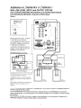
Connecting Stereo Equipment Using Low/Line Level (SEE FIGURE 4,
page 17): If your receiver or integrated amplifier has preamplifier outputs, or if you are using a separate preamplifier, the preferred connection is from the Preamplifier Output of the electronics to the Low
Level Input of the subwoofer. Use a dual RCA audio cable.
3.
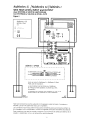
Connecting Stereo Equipment with High/Speaker Level
(SEE FIGURE 5, page 18): You also can get excellent sonic results by
connecting the High/Speaker Level Output of your receiver, integrated
12
amplifier or power amplifier to the High Level Input of the subwoofer.
Use standard speaker cable and maintain polarity + -, as well as right
and left side.
Speaker wires can be run onwards from the subwoofer directly to the
main speakers. This replaces running wires from the receiver or
amplifier to the main speakers. Twist the ends of each input wire from
the electronics together with the corresponding wire to the speakers
and insert them both into each corresponding input binding post of the
SubSeries i. Be sure to avoid all contact between wires into the separate binding posts.
B.
THE SUBSERIESTM 5i
1.
Connecting Home Theater Equipment (SEE FIGURE 3, page 16):
Please see the instructions for the SubSeries 1.
2.
Connecting Stereo Equipment using Low/Line Level (SEE FIGURE 4,
page 17): For this preferred connection, please see the instructions for
the SubSeries 1. Additionally, you may need to use V-connectors at the
Preamplifier Output to also send signals to the Power Amplifier/Main
Input.
3.
Connecting Stereo Equipment with High/Speaker Level (SEE FIGURE
5, page 18): Vou also can get excellent sonic results by connecting the
High/Speaker Level Output of your receiver, integrated amplifier or
power amplifier to the High Level Input of the subwoofer. Use standard
speaker cable and maintain polarity + -, as well as right and left side.
High/Speaker Level Output from the subwoofer allows speaker wires
to be run onwards easily from the subwoofer directly to the main
speakers. This replaces running wires from the receiver or amplifier to
the main speakers. The signals from the SubSeries 5i to the main
speakers are looped through, full-range.
C. THE SUBSONIC 6;
1.
Connecting Home Theater Equipment (SEE FIGURE 3, page 16):
Please see the instructions for the SubSeries 1.
2.
Connecting Stereo Equipment using Low/Line Level (SEE FIGURE 4,
page 17): If your receiver or integrated amplifier has preamplifier outputs, or if you are using a separate preamplifier, the preferred connection is from the Preamplifier Outputs of the electronics to the Low/Line
Level Inputs of the subwoofer. Use a dual RCA audio cable and maintain
right and left. (Vou may need to use V-connectors at the preamplifier
outputs to also send signals to the Power Amplifier/Main Inputs.)
13
Connecting the Low/Line Level Outputs from the subwoofer back to the
Power Amplifier Inputs is an important option. The Low/Line Level
Inputs of the subwoofer are internally processed through an active high
pass filter (at 12dB/octave below 80Hz) to the Low/Line Level Outputs
of the subwoofer. Connecting the low/Line Level Outputs from the subwoofer back to the Power Amplifier Inputs delivers the processed signal, with reduced low frequency content, to the main speakers. With less
low frequency demands, the main speakers can play louder. Particularly
with smaller and/or less efficient main speakers, relieving speakers other
than the subwoofer of the demands of reproducing low frequencies will
allow greater sound output and dynamic capabilities from the other
speakers and from the system overall.
3.
Connecting Stereo Equipment with High/Speaker level (SEE FIGURE
5, page 18): You also can get excellent sonic results by connecting the
High/Speaker level Outputs of your receiver, integrated amplifier or
power amplifier to the High/Speaker level Inputs of the subwoofer. Use
standard speaker cable and maintain polarity, as well as right and left.
High/Speaker level Outputs from the subwoofer allow speaker wires
to be run onwards easily from the subwoofer directly to the main
speakers. The signals from the SubSeries 5; to the main speakers are
looped through, full-range. This replaces running from the receiver or
amplifier to the main speakers. The High/Speaker level Inputs of the
SubSeries 6; are internally processed through a passive high pass filter
(at 6dB/octave below 100Hz) to the Speaker level Outputs of the subwoofer. Connecting the Speaker level Outputs from the subwoofer
directly to the main speakers delivers the processed signal, with
reduced low frequency content. With less low frequency demands, the
main speakers can play louder.
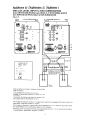
D. Using Multiple Subwoofers (SEE FIGURE 6, page 19)
Particularly in difficult rooms with difficult layouts, using two subwoofers
is an alternative to smooth, as well as increase bass response. One subwoofer can be located to increase response, with the second subwoofer
located to smooth response. The wiring of two subs in a system is illustrated in Figure 6 (the two subs do not need to be identical). Please refer
to Section V, Multiple Subwoofers for further information.
VII.
SET-UP CALIBRATION
The following procedure assumes your PSB subwoofer is installed and connected. If possible, work in a team with another person: one listening, one making
subwoofer-control adjustments.
14
A.
Set Sub Volume to 0, Sub Cut-Off Frequency to 50Hz. Set any loudness,
bass and treble, and/or equalizer controls on your preamplifier or integrated
amplifier or receiver, or other components, to their nominal (midpoint or off)
positions. Ensure the LFE Input/Crossover bypass switch is set to off unless
the subwoofer is connected to the LFE/Subwoofer output of your
receiver/processor and the output is low pass filtered.
B.
Playa familiar compact disc, LP, or video soundtrack that includes substantial deep-bass content over an extended section. Your PSB dealer can help
you select a few such titles.
C.
Gradually turn the Sub Volume control clockwise until you achieve natural
balance between the subwoofers deep-bass output and your main left and
right loudspeakers.
D.
Slowly turn the Sub Cut-Off Frequency control clockwise to reach the best
mid-bass blend with your main left and right speakers. This will be the point
at which the upper bass retains solid impact and fullness. Boom or muddiness
is the result if the control is too high. A thin, "reedy" quality to the mid-bass
such as deep male voices (FM announcers; Darth Vader) is the result if the
control is too low.
E.
Switch the Phase control between 00 and 1800 several times, leaving it in the
position that yields the fullest low to mid bass output. You will now probably
want to repeat steps C& Dto double-check the subwoofer blend.
Cycling through steps C & D several times with slightly different settings of both
the Sub Volume and Sub Cut-Off Frequency controls will help you get the most
musical performance from your PSB Subwoofer and your system. The best
combination is that which yields the most solid very-low-bass sounds, without
mid-bass boom or a gap in response between the subwoofer and the main
speakers.
As you will discover, the Sub Cut-Off Frequency and Sub Volume controls are
interactive. Raising the latter while lowering the former can have the effect of
extending deep-bass response somewhat, with a small sacrifice in overall loudness capability (this will still be well beyond the full-range loudness capability of
most systems). In general, for well-recorded acoustic music the lowest Sub
Cut-Off Frequency setting that yields a smooth transition between subwoofer
and main speakers is often the best choice, and will promote deeper low-bass
extension.
Note: The Sub Volume control is not a bass-boost or volume control. It is a
set-and-forget adjustment, not intended for day-to-day adjustment. Use your
preamplifier or receiver/integrated amp tone controls to modify program tonal
balance.
15
SubSeries J / SubSeries 5; /SubSeries 6;
With SUBWOOFER/LFE INPUT
INTEGRATION avec RECEPTEUR AN / ENTREE LFE
INTEGRACION con RECEPTOR de AUDIO-VIDEO/ENTRADA LFE
Figure 3
'I!>
Rib__
I!>
e__
...-_..., 1.. 0
SubSeries 1CE
SEE
To PA 250V
(8)
22C'·24(1V"lt SOi6\.:HZ
(e)
-
----+-..
•
I--~
•
MODEL ONLY
(A)
I ...::..-....
- - I \::::1.1....
• 1-.
leO. 0
I _'Ml I •
L_="'_J
---
•
•
....-(8) (8)-,..
-(8) @-
[Q]
Hook up same for all models-SubSeries 1
Back Plate used for illustration
Le raccordement est Ie meme pour tous
les modeles-Plaque arriere SubSeries 1
utilisee des fins d'illustration.
La conexion es la misma para todos los
modelos-Se usa el panel posterior del
SubSeries 1como ilustracion
'-j:'
,""V
~---"'-A
._- _ ._ _ .
~
C€
"V
/
...... _ . _ . _ .
====-=:_-=~
-_.-
SU&l.FE OVT
'-j:'
~
SPKA IL
(~~-~
AN RECEIVER,
INTEGRATED AMPLIFIER,
PREAMPLIFIER OR
PROCESSOR
==
~-
RIGHT
SPEAKER
LEFT
~~~~~ SPEAKER
Use this configuration to connect the subwoofer to an AN receiver or processor's subwoofer/lFE output.
The lFE input/crossover bypass switch should be set to active only if your AN receiver/processor
subwoofer/lFE output is low pass filtered.
Utilisez cette configuration pour raccorder Ie haut-parleur d'extreme grave it un recepteur AN ou it la
sortie sub/lFE du processeur. l'interrupteur de I'entree/derivation du filtre separateur de frequences lFE
doit etre regie it « active" seulement si votre sortie de recepteur/processeur/caisson de grave lFE est
filtree bas-niveau.
Use esta configuracion para conectar el subgrave a un receptor de audio/video 0 a la salida sub/lFE de
un procesador. EI interruptor que permite pasar por alto Ie entrada lFE/red divisora debe ponerse un la
posicion activa sola mente si hay un filtro de paso bajo en la salida para altavoz subgrave del receptorde
audio-video/procesador.
16
SubSeries 6; / SubSeries 5; / SubSeries 1
With LOW LEVEL INPUT and OUTPUT OPTION
Avec L'OPTION D'ENTREE BAS-NIVEAU et de SORTIE BAS-NIVEAU
Con OPCION de ENTRADA y SALIDA a NIVEL BAJO
Figure 4
SubSeries 6i CE
MODEL ONLY
SEE
(A)
(e)
T 1.25A 250V
[Q]
CE:
Hook up same for all models-SubSeries
6i Back Plate used for illustration
Le raccordement est Ie meme pour tous
les modeles-Plaque arriere SubSeries
6i utilisee des fins d'illustration.
La conexi6n es la misma para todos los
modelos-Se usa el panel posterior del
SubSeries 6i como ilustraci6n
.._ -
[g]
(e)
8- ~ @·(8)
[I~.;r)
~.
A ~ ~'-J:"f
~
@
_....... <._..-
(A)
~====-_-:'".::..
:::.-.='..::--_._.
@
Ell
PREAMPLIFIER
$PKQ
SPi(p' R
+ -
R
INPUT
+
L
MAIN
_
-
IN
-ALTERNATE: - - - - - - - - RECEIVER OR INTEGRATED
AMPLIFIER WITH PRE-AMP
OUT AND MAIN-IN JACKS
r;==I==lt=~
~----------------This method of wiring does not limit low frequenCies
reaching left and right main speakers
Ce cablage ne limite pas /es basses frequences
atteignant les haut-parleurs principaux gauche et
droite
+
+
RIGHT
SPEAKER
LEFT
~=========~ SPEAKER
Esta conexi6n no limita las frecuenClas bajas que
"egan a los altavoces principa/es derecho e
izquierdo
Low level connections wire the subwoofer to a preamplifier or to the "pre-out" jacks of an integrated amplifier or
receiver, using standard RCA cables.
Les raccordements bas-niveau relient Ie haut-parleur d'extreme grave it un preamplificateur ou aux bornes
«sortie preamplificateur» d'un preamplificateur, d'un amplificateur integre ou d'un recepteur au moyen de cables
RCA standard.
Para conexi6n al nivel bajo se conecta el subgrave al pre-amplificador 0 a los conectores "pre salida" de un
amplificador integrado 0 receptor usando cables comunes tipo RCA.
17
SubSeries 5; / SubSeries 6; / SubSeries I
With HIGH LEVEL INPUT and OUTPUT
Avec ENTREE et SORTIE HAUT-NIVEAU
Con ESTRADA y SALIDA de NIVEL ALTO
Figure 5
SubSeries 5i CE
MODEL ONLY
SEE
1 OA ;,~v
(A)
-
(8)
22C 2~OV~5C Ead
(e)
RECEIVER,
INTEGRATED
AMPLIFIER
or POWER
..1 AMPLIFIER
~...~~ _~ ~ +D~ _0
.....S_PK_R_IR_S_PK_A_Il
@
_- -...
[QJ
... .....
lAl.-Jl'l
CE
.
-0
$
.
0
I"'..!.----,
@
~F=======::i!~=~:::!J
::~.~'1
:~~~:l---tf~:hJ:tlJ=====~
..""'LII_-
rr===========F==::t=
I_~ ~-.-( '1"I
____ ":;: """"'"
I
I
CB I~J-_{E~
...- - - - - - - - - . . . -........-..l!~._
VI
l+)
-~=..
<t! -!I:I;fi:l-I(A)
K____
-- (B);~~.iH; ~~
(C)
II
:
I
,
I
11'\
,~
A-----A
~D
MIIMII-'
11.\
~ - - : : . ' : . - ~ \;t7
Jl!!!S!:.,i!s .l. ~P!'~N_l
I
I
I
I
I
I
I
IL
To RIGHT SPEAKER
From RI<IHT RECEIVER or AMP
To RIGHT SPEAKER
.._.-.
4\
~
_
§: @);C
~
"From RI<lKT RECEIVER or AMP
.,
~..::===:..:':.:..
~~~-=
• 0
O·
From lEFT RECEIVER or AMP
To lEFT SPEAKER
~ From lEFT RECEIVER or AMP
- 0
~ To lEFT SPEAKER
I
I
I
I
I
I
I
JI
Hook up same for SubSeries 6i-SubSeries 51 Back
Plate used for illustration.
Le raccordement est Ie meme pour SubSeries
6,-Plaque arriere SubSeries 51 utili see pour fins
d'illustration.
La conexi6n es la misma para SubSeries 6/-Se usa el
panel posterior del SubSeries 51 como ilustraci6n.
RIGHT
~==-==-==-==-~
LEFT
SPEAKER
SPEAKER
~
High level connections wire the subwoofer to the speaker output terminals of a receiver or
amplifier, just as if the subwoofer was a pair of speakers.
Les connexions haut-niveau relient Ie haut-parleur d'extreme grave aux bornes de sorties h.-p.
d'un recepteur ou d'un amplificateur, comme s'il s'agissait d'une paire d'enceintes acoustiques.
Para conexi6n al nivel alto se conecta el subgrave a las terminales de salida para altavoz de un
receptor 0 amplificador como si se tratase de un par de altavoces.
18
-=u
SubSeries 6i / SubSeries 5i /SubSeries 1
With LOW LEVEL INPUT to TWO SUBWOOFERS
Avec ENTREE BAS-NIVEAU vers DEUX H.-P D'EXTREME GRAVE
Con ENTRADA de NIVEL BAJO a DOS SUBGRAVES
Figure 6
H.-P. D'EXTREME GRAVE N 1
DROIT
SUB #1
RIGHT
H.-P. D'EXTREME GRAVE N 2
GAUCHE
e
~
- - III
e
e
,(§j,!..- ....::".:..
'~S?2llll !
-.
9
$
------.@ @-
=I~l e
e
SUB #2
LEFT
...
~
e
-.-
$
-(9) (9)-€) (9)- _....,
"':(8) (9)~ e
III
$
-
."",n
$
e
._-
(1)
(l)
(C)
[Q]
ICKwl
,
. ....~--- . 8- ~~.
,...... _.-.
~~
..-._--_...... '._ ......
,
~
@
@
...
(B)
n",_
(A)
--
_-~
-'--;:.
---------~.::.-._._.
@
PREAMPLIFIER
SubSeries 6i CE
MODEL ONLY
e
SEE
(Al
T 1 25A 250V
(B)
220-240V .... SO!60HZ
(el
[Q]
NPJ...,T
-
IF==IF=II===;'I
<€
-
L
MAlo\I
IN
ALTERNATE: . - - - - RECEIVER OR INTEGRATED
AMPLIFIER WITH PRE-AMP OUT
AND MAIN-IN JACKS
.
RIGHT
SPEAKER
.
LEFT
~=========~ SPEAKER
Hook up same for all models-SubSeries 6i Back Plate
used for illustration.
Le raccordement est Ie meme pour tous les
modeles-Plaque arriere SubSeries 6/ utilisee pour fins
d'illustration.
La conexi6n es la misma para todos los modelos-Se
usa el panel posterior del SubSeries 6i como
For this type of connection two RCA "Y" adapters are required to be plugged into the pre-out jacks of a
preamplifier or integrated amplifier or receiver.
Pour ce genre de connexion, il faut brancher deux adaptateurs en «Y» RCA sur les prises de sortie
d'un preamplificateur, d'un amplificateur integre au d'un recepteur.
Para esta conexi6n se necesita enchufar dos adaptadores RCA tipo "Y" a los conectores de salida de
un preamplificador, amplificador integrado 0 receptor.
19
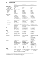
VIII.
SPECIFICATIONS
SubSeries 5i
SubSeries 6i
36-150Hz
32Hz
30-150Hz
27Hz
29-150Hz
26Hz
(RMS, Clipping <10% Time)
110 Watts
140 Watts
280 Watts
Class AB
Discrete MOSFET
Output Devices
150 Watts
225 Watts
450 Watts
Class H/BASH
Discrete MOSFET
Output Devices
225 Watts
325 Watts
650 Watts
Class H/BASH
Discrete MOSFET
Output Devices
8" (203mm)
Polypropylene Cone
Rubber Surround
1)12" (38mm) Voice Coil
28 oz (794g) Magnet
+20 oz (567g) Shielding Magnet
10" (250mm)
Polypropylene Cone
Rubber Surround
11/;>" (38mm) Voice Coil
28 oz (794g) Mag net
+28 oz (794g) Shielding Magnet
12" (300mm)
Polypropylene Cone
Rubber Surround
2" (50mm) Voice-Coil
53 oz (1503g) Magnet
Crossover
Variable 50Hz-150Hz
24dB/octave Linkwitz-Riley
Low Pass Filter
Variable 50Hz-150Hz
24dB/octave Linkwitz-Riley
Low Pass Fi Iter
Variable 50Hz-150Hz, LR4
24dB/octave Linkwitz-Riley
Low Pass Filter
Internal Volume
0.68 cu It (19.3 liter)
1.01 cu II (28.6 liter)
2.38 cu It (67 liter)
Design Type
Bass Reflex
1 x 8" Front Duct (25mm x 203mm)
Radiused Externally
Video Shielded
Bass Reflex
2 x 2" Front Porls (508mm)
Radiused Internally and Externally
Video Shielded
Bass Reflex
2 x 2 5/8" (66.7mm) Front Ports
Radiused Internally and Externally
(W x H x D)
9 5/8 x 13 1/4 x 14 1/2"
244 x 337 x 368mm
Plus 1" (25mm) Feet
123/8 x 16 112 x 14 7/8"
314 x 419 x 378mm
Plus 7/8" (22mm) Feet
15 x 19 7/8 x 19 1/4"
381 x 505 x 489mm
Plus 1" (25mm) Feet
23.5 Ib (10.8kg)/each
27.5 Ib (12.6kg)/each
31 Ib (14kg)/each
34 Ib (16kg)/each
461b (20.9kg)/each
541b (24.6kg)/each
FINISH
Black Textured, Sienna or
Maple Vinyl Veneer
Black Ash Vinyl
Black Ash Vinyl
CONNECTIONS
Low/Line Level/LFE Input
High/Speaker Level Input
Low/Line Level/LFE Input
High/Speaker Level Input
and Output
Low/line Level/lFE Input and Output
High/Speaker Level Input
and Output
80 Hz High Pass Filter
12 dB/octave Butterworth
High Level High Pass
6 dB/octave Filter
FEATURES
Front Mounted Volume
and Crossover.
Phase, Crossover Bypass and
On-Standby/Oil
5-way Binding Posts and
Gold-plated RCAs
Front Mounted Volume
and Crossover.
Phase, Crossover Bypass and
On-Standby/Oil
5-way Binding Posts and
Gold-plated RCAs
Front Mounted Volume
and Crossover.
Phase,
On-Standby/Oil
5-way Binding Posts and
Gold-plated RCAs
Feet with Adjustable Spikes
& Rubber Levelers
SubSeries 1
FREQUENCY RANGE
Response
On Axis @ O· ±3dB
LF Cutoff -10dB
AMPLIFIER POWER-INTERNAL
Continuous
Dynamic
Peak
Type
ACOUSTIC DESIGN
Woofer
SIZE
WEIGHT
Net
Shipping
(Anechoic Chamber)
~:
C€
or
C€
ui"106416
POWER
Input
Fuse
120V,60Hz
1.6A, 250V
220-240,50/60Hz
120V,60Hz 220-240V, 50/60Hz
TO.8A, 250V,
2.0A, 250V T1.0A, 250V,
5mm x 20mm
5mm x 20mm
*Manufactured by Littlefuse Type 313 or Equivalent
~,
or
NRTUC
120V, 60Hz
2.5A, 250V
220-240V, 50/60Hz
T1.25A, 250V,
5mm x 20mm
All specifications are subject to change without notice. PSB, Alpha and SubSeries are trademarks of Lenbrook Industries Limited.
© 2006. PSB Speakers, a division of Lenbrook Industries Limited. All rights reserved.
20
C€
ui"Ui.
PSB Speakers
633 Granite Court
Pickering, Ontario L1W 3K1
Canada
www.psbspeakers.com
888-772-0000 (North America)
905-831-6555 (I nternational)
Fax: 905-837-6357
Enregistrez votre garantie sur Internet des maintenant
et courrez la chance de gagner des enceintes PSB.
Visitez Ie : www.psbspeakers.com/warranty
633 Granite Court, Pickering (Ontario)
Canada L1W3K1
Telephone: (905) 831-6555
(888) 772-0000
Telecopieur: (905) 837-6357
www.psbspeakers.com
Un membre du groupe de societes Lenbrook
GARANTIE LlMITEE
_
PSB Speakers, une division de les Industries lenbrook
limitee, garantie les produits ci-apres pour la duree
indiquee.
Titulaire de la presente garantie
La presente garantie est accordee uniquement
initial.
Produits
Enceintes acoustiques et haut-parleurs d'extreme grave
asservis
Notre contribution
Nous payons tous les frais de main-d'rnuvre et de materiau
pour les articles couverts par la garantie ; les frais d'expedition
sont abordes dans la prochaine rubrique de la presente
garantie.
Duree de la garantie
Tous les haut-parleurs PSB et les caissons de graves extremes
sont garantis 5 ans. Les amplificateurs PSB, y compris ceux
utilises dans nos « haut-parleurs actifs » (tels que les caissons
de graves extremes) sont garantis 1an.
Etendue de la garantie
Sous reserve des dispositions ci-apres, la presente garantie
couvre les pieces et la main-d'rnuvre en vue de corriger tout
vice de materiau et de fabrication. Sont exclus de la presente
garantie:
1. tout dommage, degradation, mauvais fonctionnement ou
defaillance resultant des situations suivantes :
a. accident, cas de force majeure, mauvaise utilisation,
negligence au modification intempestive du produit ;
b. installation, enlevement out entretien incorrect et
manquement a se confirmer aux directives fournies
pour Ie produit ;
c. reparation ou tentative de reparation par quiconque n'est
pas autorise par PSB Speakers areparer Ie produit;
d. envoi du produit (Ia demande d'indemnisation doit etre
adressee au transporteur) ;
e. toute cause autre qU'une defectuosite du produit.
2. Ie nettoyage, I'installation initiale, une verification ne
permettant pas de detecter de defectuosite ou les frais
engages pour I'installation, I'enlevement ou la reinstallation
du produit.
3. les produits dont Ie numero de serie aete efface, modifie ou
enleve.
4. les accessoires, y compris, sans s'y limiter, les cables, les
accessoires d'installation et supports et les cordons
d'alimentation detachables.
5. les produits utilises ades fins commerciales ou dans une
application industrielle ou commerciale.
6. tout produit achete a I'exterieur du pays dans lequel la
reparation est demandee. y compris les possessions et les
territoires de ce pays.
7. tout autre probleme qui ne constitue pas un vice du produit.
8. Pour tout produit non achete aupres d'un revendeur agree
PSB Speakers. Si vous n'etes pas certain qU'un revendeur
est « agree », verifiez sur notre Iiste de revendeurs ou
appelez PSB Speakers.
a I'acheteur
Pour obtenir Ie service apres-vente
1. Se votre produit doit etre repare, veuillez I'apporter avotre
depositaire PSB Speakers en prenant soit d'apporter
egalement votre facture ou acte de vente original. Si vous
avez besoin d'aide pour connaltre I'identite de votre
depositaire PSB Speakers, veuillez visiter Ie site web de PSB
Speakers ou communiquez directement avec celle-ci.
2. Vous devez acquitter tous les frais d'expedition si votre
produit doit etre expedie en vue de Ie faire reparer.
Cependant, si les reparations necessaires sont couvertes
par la garantie, nous paierons tous les frais d'expedition de
retour vers n'importe quelle destination aI'interieur du pays
dans lequella reparation est demandee.
3. Lorsqu'une reparation sous garantie est demandee, vous
devez produire I'acte de vente original, la facture ou une
autre preuve d'achat date.
limite des garanties implicites
Toutes les garanties implicites, y compris les garanties de
qualite marchande et d'aptitude a un but particulier, sont
limitees ala duree de la presente garantie.
Exclusion des dommages
La responsabilite de PSB Speakers a I'egard de tout produit
defectueux se limite a la reparation ou au remplacement du
produit, au gre de PSB Speakers. PSB Speakers ne peut etre
tenue responsable des dommages causes atout autre produit
par suite de la defectuosite des produits PSB Speakers, ni des
dommages resultant des desagrements ou pertes d'utilisation
du produit, ni d'autres dommages, directs, indirects ou autres.
les lois de I'etat (ou de la province) au regard de la
presente garantie
Certains etats et certaines provinces n'autorisent pas les
clauses Iimitant la duree des garanties tacites ou I'exclusion
des dommages indirects ou accessoires, ou I'une et I'autre.
Par consequent. il est possible que les clauses restrictives
ou exclusives ci-dessus ne s'appliquent pas avous.
La presente garantie vous accorde des droits legaux precis; il
se peut que vous en ayez d'autres, qui peuvent varier d'un etat
(ou d'une province) aun autre.
La presente garantie ne s'applique que dans Ie pays ou Ie
produit aete achete, incluant ses possessions etterritoires.
Conservez cet enonce de garantie, incluant la date
d'enregistrement et votre preuve d'achat, dans vos dossiers.
OM-010 Rev. 06/06
I!!l
633 Granite Court, Pickering, Ontario
Canada L1W3K1
Phone: (905) 831-6555
(888) 772-0000
Fax:
(905) 837-6357
www.psbspeakers.com
LIMITED WARRANTY
PSB Speakers, a division of Lenbrook Industries Limited,
warrants the following products for the periods indicated:
Products
Loudspeakers and Powered Subwoofers
How Long Does the Warranty Last?
All PSB loudspeakers and subwoofer drivers have a 5-year
warranty. PSB amplifiers, including the amplifiers used in
our "powered speakers" (such as powered subwoofers)
have a 1 year warranty.
What is Covered and What is Not Covered?
Except as specified below, this warranty covers parts and
labor to correct all defects in materials and workmanship.
The following are not covered by the warranty:
1. Damage, deterioration, malfunction or failure to meet
performance specifications resulting from:
a) Accident, acts of nature, misuse, abuse, neglect or
unauthorized product modification.
b) Improper installation, removal or maintenance, or failure
to follow instructions supplied with the product.
c) Repair or attempted repair by anyone not authorized by
PSB Speakers to repair the product.
d) Any shipment of the product (claims must be presented
to the carrier).
e) Any cause other than aproduct defect.
2) Cleaning, initial set-up, check-ups with no defects found, or
charges incurred for installation, removal or reinstallation of
the product.
3) Any product on which the serial number has been defaced,
modified, or removed.
4) Accessories, including but not limited to, cables, mounting
hardware and brackets, and detachable power cords.
5) Any product used in any trade or business or in an industrial
or commercial application.
6) Any product purchased outside the country of service, its
possessions orterritories.
7) Any problem other than aproduct defect.
8) Any product not purchased from an authorized PSB
Speakers Dealer If you're not sure a dealer is "authorized",
check our dealer locator or call PSB Speakers.
Register Your Warranty Online Now
for a chance to win PSB speakers.
Visit: www.psbspeakers.com/warranty
AMember of the Lenbrook Group of Companies
_
How You Can Get Service
1) If your unit needs service, please take your speaker with the
original invoice or bill of sale to your PSB Speakers dealer. If
you need assistance locating a PSB dealer please look on
PSB's internet website or contact PSB directly.
2) You must pay any shipping charges if it is necessary to ship
the product for service. However, if the necessary repairs
are covered by the warranty, we will pay the return shipping
charges to any destination within the country of service.
3) Wherever warranty service is required, you must present
the original dated sales receipt, invoice, or other proof of
purchase.
Limitation of Implied Warranties
All implied warranties, including warranties of merchantability
and fitness for a particular purpose, are limited in duration to
the length ofthis warranty.
Exclusion of Damages
PSB Speakers' liability for any defective product is limited to
repair or replacement of the product at PSB's option. PSB shall
not be liable for damage to other products caused by any
defects in PSB's prOducts, damages based upon
inconvenience or loss of use of the product, or any other
damages, whether incidental, consequential, or otherwise.
How State (Provincial) Law Relates to the Warranty
Some states do not allow limitations on how long in implied
warranty lasts and/or do not allow the exclusion or limitation of
incidental or consequential damages, so the above limitations
or exclusions may not apply to you.
This warranty give you specific legal rights, and you may also
have other rights, which vary, from State (Province) to State
(Province).
This warranty is enforceable only inside the county of
purchase, its possessions orterritories.
Who May Enforce the Warranty?
This warranty may be enforced only by the original purchaser.
What We Will Pay For
We will pay for all labor and material expenses for items
covered by the warranty. Payment of shipping charges is
discussed in the next section of this warranty.
Keep this warranty statement including the registration date
with your proof of purchase for your records.
OM-010 Rev. 06/06