1
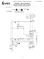
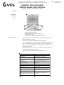
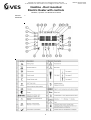
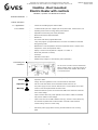
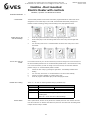
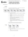
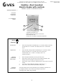
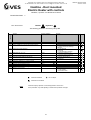
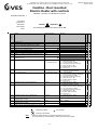
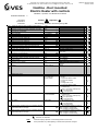
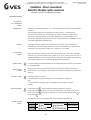
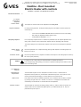
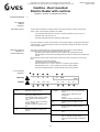
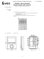
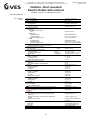
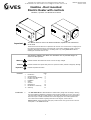
VES
VES Eagle Close Chandlers Ford Ind. Est Eastleigh Hampshire SO53 4NF
Tel: 08448156060 Fax: 08702 404550 E-mail: [email protected] Web: www.ves.co.uk
ORIGINAL INSTRUCTIONS
VES Ref: ID 899
Heatline - Duct mounted
Electric Heater with controls
Installation, Operation and Maintenance Manual
Important
!
This manual must be read in full before Installation, Operation and maintenance
of the units
Please ensure that this document is passed to the end user. This manual forms an integral part of
the product and should be kept for the working life of the product. Additional copies of this and
supporting documents are available by contacting VES or by visiting www.ves.co.uk and
following the ‘Download O & M’s’ link.
The following symbols used within this document refer to potential dangers or
advice for safe operation
Warning
Indicates hazards associated with electric current and high voltages
Caution
Important
Indicates hazards that require safety advice for personnel and/or potential unit/property damage
!
Indicates important information
1
2
3
4
5
6
7
8
9
10
Introduction
Unit Description
Receipt of Goods/Handling
Product Overview
Installation
Wiring
Controls
Maintenance
Declaration of conformity
Warranty
Contents
Introduction 1
Page
1
2
2
2
3
5
7
25
26
27
The VES HEATLINE Duct Mounted Electric Heater Battery brings wider versatility to existing
and new ventilation installations. Intelligent control options for BMS or LCD room units, plus a
Thyristor heater make this the ideal solution to accurately heat individual rooms. HEATLINE is
also both simple to install and maintain. Duct sizes ranging from 100 to 600 Square/Round.
For further technical details regarding dimensions and weights, contact VES on
08448 15 60 60, quoting the sales order (SO) number and the unit type as found on the unit
nameplate or visit www.ves.co.uk.
1
VES
VES Eagle Close Chandlers Ford Ind. Est Eastleigh Hampshire SO53 4NF
Tel: 08448156060 Fax: 08702 404550 E-mail: [email protected] Web: www.ves.co.uk
ORIGINAL INSTRUCTIONS
VES Ref: ID 899
Heatline - Duct mounted
Electric Heater with controls
Installation, Operation and Maintenance Manual
Unit Description
2
1
Point Description
Product
2
Duct size
3
4
KW
Thyristor Heater Supply
5
Control Options
Point variants
HLD
HLC
100 to 600
100 to 600
0.5 to 32
1x1
1x3
BMS
Part Number Coding
CP
Typical example
HLC200/4.5KW/1x1/CP
1
Receipt of Goods
Details (as appropriate)
Square Ducting
Circular Ducting
Diameter size for circular ducting
Lengths of sides for square ducting
KW rating
1 Phase
3 Phase
V/F enabled and 0-10V heat demand
control from remote source
LCD room unit control
3
2
3
4
5
Immediately upon receipt of goods, check for possible damage in transit.
Also check to ensure that any ancillary items are included. These will normally be supplied fitted or
taped to the unit (in the case of small items).
In the event of any damage having occurred or if any item found to be missing, it is essential to
inform VES Andover Ltd. within 3 working days of delivery quoting sales order (SO) number and
the unit type as found on the unit nameplate. After this period we will be unable to accept any claim
for damaged or missing goods.
Product Overview
4.1 Features:
4
•
•
•
•
•
•
Suitable for circular (HLC) and square ducts (HLD) in various sizes
Single or three phase Thyristor heater available for modulating output
Intergrated controls for response to BMS
Optional versatile LCD room unit with built in sensor and timers
Easy installation to existing ductwork systems
Exstensive built-in safety features mez flange or self sealing spigots.
Use with VES ECOBox, filter and fan kits for compact, efficient heat recovery. (Refer to page 3)
4.2 Control types:
4.2.1 BMS:
4.2.2 CP:
External control
Control option 1 - BMS V/F enabled and 0-10V dc control (no room unit)
•
1ph or 3ph Thyristor heater options
•
Fan control up to 4Amps 230V @ 50Hz (Run on timer required)
•
Main isolating switch with lockable handle and panel live indicator
•
Independent safety circuitry
•
Factory fitted safety interlock airflow pressure and thermal cut-out switches
•
Volt free run and trip indication
•
V/F enable and 0-10V heating demand signal required to operate unit
•
Run on timer requiring heating demand signal to be removed for a minimum of 2 minutes
before V/F system run signal is removed
Control option 2 - LCD Room Unit
As control option 1 PLUS...
•
LCD room unit with built-in room sensor and user temperature adjustment
•
On/Off/Auto control
•
Time clock setup and fan overrun timer adjustment
•
Fault display
•
Adjustable commissioning and control parameters
•
Tamperproof locking with PIN access
•
Optional duct sensor for supply air or return temperature control
2
VES
VES Eagle Close Chandlers Ford Ind. Est Eastleigh Hampshire SO53 4NF
Tel: 08448156060 Fax: 08702 404550 E-mail: [email protected] Web: www.ves.co.uk
ORIGINAL INSTRUCTIONS
VES Ref: ID 899
Heatline - Duct mounted
Electric Heater with controls
Installation, Operation and Maintenance Manual
Duct Installation 5
(Circular and
Square)
Examples for illustration purposes only
RS***
Fan c/w
circular spigots
Circular ducting
HLC****
Heatline c/w
circular spigots
Ducting where
necessary
CRSM****
Filter section
c/w circular spigots
EBXEX****
Male & Female
couplings where
necessary
Self sealing spigot
as standard on sizes
up to 560
Square ducting
Ducting where
necessary
ECO***
Ecobox unit
Securing nuts &
bolts used to join
30mm MEZ
flanges togethers
HLD****
Heatline c/w
square spigots
3
VES
VES Eagle Close Chandlers Ford Ind. Est Eastleigh Hampshire SO53 4NF
Tel: 08448156060 Fax: 08702 404550 E-mail: [email protected] Web: www.ves.co.uk
ORIGINAL INSTRUCTIONS
VES Ref: ID 899
Heatline - Duct mounted
Electric Heater with controls
Installation, Operation and Maintenance Manual
Duct Installation
Continued
5
5.1 Airflow:
Caution
Important
!
5.2 Themal Cutout
(manual):
The heater can be used for horizontal or vertical airflow. The air should be evenly
distributed across the duct and the minimum air volume as stated on the air heater name
plate must be maintained.
Every heater is provided with a thermal cutout which will break contacts when the duct
temperature rises above 130ºC. This cutout is provided to comply with M & E specifications
and will require removal of the terminal cover to reset. Supply must be isolated before
removing cover.
Warning
N.B. It is very important that all electrical connections are properly made. Elements are tested prior
to dispatch and are within tolerance of ±7½W of total load. If the elements are found to be faulty
they can be easily removed and replaced. Elements stored in damp conditions may need drying
to attain correct insulation readings - contact VES Andover Ltd, if in doubt.
5.3 Testing:
5.4 Notes:
1
Warning
2
Caution
Important
!
3
4
Supply to Heatline should be 1ph or 3ph and a neutral - refer to name plate for correct
supply.
The heater is fitted with a manual reset high temperature cutout which has NC
(normally closed) terminals and an air flow pressure switch. This is connected
in series with the main contactor coil circuit, to remove power from the heater in the
event of over-temperature or airflow failure. Under no circumstances is this
circuit to be bypassed.
Ensure sufficient earth connection to termainal is provided.
The speed controller must not switch off fan independent of control system or allow
airflow to fall below stated volume on the electric heater battery.
4
VES Eagle Close Chandlers Ford Ind. Est Eastleigh Hampshire SO53 4NF
Tel: 08448156060 Fax: 08702 404550 E-mail: [email protected] Web: www.ves.co.uk
VES
ORIGINAL INSTRUCTIONS
VES Ref: ID 899
Heatline - Duct mounted
Electric Heater with controls
Installation, Operation and Maintenance Manual
6
Warning
6.1 BMS 1ph
example wiring
diagram:
!
Important
Caution
A1
B
A
3
2
A1
S3
S2
A1
T1 5A3 3A1
L1 6A4 4A2
2 4 6
F1
T1
2
H1
X2
K3
.6
1 3 5
2
X1
Q2
1
Q1
1
3
5
E
2
4
6
L
N
1
2
230V 1ph
AC
50HZ
10v
0v
1
3
S1
FAN RUN ON TIMER REQUIRED.
TURN OFF 0-10VDC HEAT DEMAND
SIGNAL FOR 2 MINUTES BEFORE
REMOVING FAN ENABLE SIGNAL.
4
5
HEAT DEMAND
SIGNAL. 0-10VDC
INPUT
VOLT FREE
UNIT ENABLE
K1
A2
K2
A2
K3
A2
VOLT FREE RUN & TRIP
SIGNAL (230V AC RATED)
4A AC3
230VAC @50HZ
V/F
TRIP
FAN RUN
SIGNAL
4A MAX RATING
4A AC3
230VAC @50HZ
24
11
K2
K1
.5 12 .5
14
11
K1
.5
5
6
2
7
1
8
21
9
Q3
V/F
RUN
Note: Please refer to order
acknowledgement for specific controls
wiring information and heater load.
COM
Wiring
VES Eagle Close Chandlers Ford Ind. Est Eastleigh Hampshire SO53 4NF
Tel: 08448156060 Fax: 08702 404550 E-mail: [email protected] Web: www.ves.co.uk
VES
ORIGINAL INSTRUCTIONS
VES Ref: ID 899
Heatline - Duct mounted
Electric Heater with controls
Installation, Operation and Maintenance Manual
6
Warning
!
VOLTFREE RUN & TRIP
SIGNAL (230V AC RATED)
4A AC3
230VAC @50HZ
A1
B
3
A
2
A1
S3
REMOTE V/F
ENABLE SIGNAL
(LINK IF NOT
REQUIRED) SELV
Q1
GND
22
14
L
X1 M
OPTIONAL DUCT
TEMP SENSOR
FOR NON
ROOM TEMP
CONTROL CPEL1011
(RESET P38 TO 1)
CUSTOMER
CONNECTIONS
N
EHB
X2
2
Q1
1
3
5
2
4
E 6
N
1
2
1
H1
3
4
X1
5
6
L
D1
21
11
K1
.5
2T1 3A1
1L1 4A2
2 4 6
2
K3
.6
1 3 5
7
1
8
Q2
9
K2
.5
10
230V 1ph
AC
50HZ
Y1
11
12
S1
X2 M
13
14
6
CPEL1011
ROOM MOUNTED CONTROLLER
S2
A1
K1
A2
K2
A2
K3
A2
COM
44
K1
.5
34
31
15
16
2
17
1
11
K2
K1
.5 12 .5
18
41
19
Q3
V/F
RUN
Note: Please refer to order
acknowledgement for specific controls
wiring information and heater load.
V/F
TRIP
6.1 CP 1ph example
wiring diagram:
Important
Caution
FAN RUN
SIGNAL
4A MAX RATING
4A AC3
230VAC @50HZ
Wiring Continued
VES
VES Eagle Close Chandlers Ford Ind. Est Eastleigh Hampshire SO53 4NF
Tel: 08448156060 Fax: 08702 404550 E-mail: [email protected] Web: www.ves.co.uk
ORIGINAL INSTRUCTIONS
VES Ref: ID 899
Heatline - Duct mounted
Electric Heater with controls
Installation, Operation and Maintenance Manual
Controls
7
7.1 CP Option
Operation
Layout:
1
3
2
4
1 Operating mode button / Esc
2 Button to enter the time and to set the timers
3 Fan mode button / OK
4 Rotary knob for setpoint and parameter adjustment
Button Operation:
•
When the thermostat is in normal operation, the actual operating mode and
status are indicated by symbols
•
When a button is pressed, the RDG goes into mode selection
•
The LCD backlight will turn on, all possible mode selection options (symbols) will
turn on, indicator element (arrow) will appear on the current mode/status
•
When the button is pressed again, the indicator element will change to the next
mode symbol and so on
•
After the last press and a timeout of 3 seconds, the newly selected mode is
confirmed, the other elements disappear
•
After a timeout of 20 seconds, the LCD backlight will turn off
User acti on
Effect, descri pti on
Press left button
Go i nto Operati ng mode selecti on
Press left button >3 seconds
Set thermostat to protecti on mode
Keep left button depressed and turn rotary
knob clockwi se
Acti vate temporary ti mer "Extend Presence"
and set the ti me (for detai ls, see page 12)
Keep left button depressed and turn rotary
knob counterclockwi se
Acti vate "Extend C omfort mode" (for detai ls,
se e p a g e 2 1 )
Press ri ght button >3 seconds
Acti vate / D eacti vate button lock
Press ri ght button
C hange fan mode
Turn rotary knob
Adjust the room temperature setpoi nt
Press left and ri ght button >3 seconds,
release, then press ri ght button >3 seconds
Go to parameter mode "Servi ce Level"
Press left and ri ght button >3 seconds,
release, then press left button >3 seconds,
then turn rotary knob counterclockwi se mi n.
1/2 rotati on
Go to parameter mode "Expert Level",
di agnosti cs.
Press centre button
Go to ti mer setti ngs
7
VES
VES Eagle Close Chandlers Ford Ind. Est Eastleigh Hampshire SO53 4NF
Tel: 08448156060 Fax: 08702 404550 E-mail: [email protected] Web: www.ves.co.uk
Heatline - Duct mounted
Electric Heater with controls
Installation, Operation and Maintenance Manual
Controls
Continued:
7
8
ORIGINAL INSTRUCTIONS
VES Ref: ID 899
VES
VES Eagle Close Chandlers Ford Ind. Est Eastleigh Hampshire SO53 4NF
Tel: 08448156060 Fax: 08702 404550 E-mail: [email protected] Web: www.ves.co.uk
ORIGINAL INSTRUCTIONS
VES Ref: ID 899
Heatline - Duct mounted
Electric Heater with controls
Installation, Operation and Maintenance Manual
Controls Continued
7
7.2 Brief description:
7.2.1 Applications:
•
Controls for modulating thyristor electric heater
7.2.2 Features:
•
2 multifunctional inputs and 1 digital input for keycard contact, external sensor, etc.
•
Operating modes: Comfort, Energy Saving and Protection
•
Adjustable commissioning and control parameters
•
Minimum and maximum setpoint limitation
•
Backlit LCD
•
Auto Timer mode with 8 programmable timers
•
7-day time program: 8 programmable timers to switch over between Comfort and
Energy Saving mode
•
Maintenance of room temperature via built-in temperature sensor or external room
temperature / return air temperature sensor
•
Display of current room temperature or setpoint in °C and/or °F
•
Button lock (automatic or manual)
•
Fault input
•
Reminder to clean filters
•
Reload factory settings for commissioning control parameters
7.3 Mounting and
installation:
Do not mount on a wall in niches, bookshelves,
behind curtains, above or near heat sources, or
exposed to direct solar radiation. Mount about
1.5m above the floor.
•
Caution
Important
The room unit must be mounted in a clean, dry indoor place and must not be
exposed to water.
!
•
Comply with local regulations to wire, fuse and earth the thermostat
•
Use the correct size cables for the duct EHB controller and room unit
•
Warning
The power supply line must have an external fuse or circuit breaker with a rated
current to meet the required heater full load current.
•
Isolate the cables of inputs X1-M / X2-M and D1-GND if the conduit box carries AC
230 V mains voltage
•
Inputs X1-M and X2-M carry mains potential. If the sensor’s cables are extended,
they must be suited for mains voltage
•
Inputs X1-M, X2-M or D1-GND of different units (e.g. summer / winter switch) may
be connected in parallel with an external switch. Consider overall maximum
contact sensing current for switch rating
•
Disconnect power supply before removing the thermostat from the mounting
plate!
9
VES
VES Eagle Close Chandlers Ford Ind. Est Eastleigh Hampshire SO53 4NF
Tel: 08448156060 Fax: 08702 404550 E-mail: [email protected] Web: www.ves.co.uk
ORIGINAL INSTRUCTIONS
VES Ref: ID 899
Heatline - Duct mounted
Electric Heater with controls
Installation, Operation and Maintenance Manual
Controls Continued
7
7.3 Mounting and
installation contined
Commissioning:
Select the application and the type of control output via the DIP switches before
fitting the thermostat to the mounting plate. After power is applied, the thermostat carries out a
reset during which all LCD segments blink, indicating that the reset was correct. After the reset,
which takes about 3 seconds, the thermostat is ready for commissioning by qualified HVAC
staff. Refer to section 7.4
The control parameters of the thermostat can be set to ensure optimum performance of the
entire system. See page 15 to find out how to set.
Control sequence:
The control sequence may need to be set via parameter P01 depending on the application. The
factory setting is P01= 0 (heating only)
Calibrate sensor:
Recalibrate the temperature sensor if the room temperature displayed on the thermostat does
not match the room temperature measured. To do this, change parameter P05.
Setpoint and
setpoint setting
range limitation:
We recommend to review the setpoints and setpoint setting ranges (parameters P08…P12) and
change them as needed to achieve maximum comfort and save Energy
7.4 Control
sequences
Important
7.4.1 Sequences
overview (setting
via parameter
P01):
!
The sequence can be set via parameter P01. The thermostats can be used in systems
featuring:
•
Heating only (P01=0)
Parameter
P01=0
Sequence
Mode
7.4.2 Controls
output overview
(setting via DIP
switches):
Heating mode
The patterns of DIP switches is as follows:
ON
OFF
1
2
3
4
5
Y1/Y2= 2-position
10
VES
VES Eagle Close Chandlers Ford Ind. Est Eastleigh Hampshire SO53 4NF
Tel: 08448156060 Fax: 08702 404550 E-mail: [email protected] Web: www.ves.co.uk
ORIGINAL INSTRUCTIONS
VES Ref: ID 899
Heatline - Duct mounted
Electric Heater with controls
Installation, Operation and Maintenance Manual
Controls Continued
7
7.5 Fan control:
The HLC/HLD unit has single speed fan control only.
Fan overrun for
electric heater
(CP option only):
When the electrical heater is switched off, the fan overruns for at least 3 minutes (parameter
P54 factory set by VES) to avoid over temperature of the electrical heater or prevent the
Caution
Important
thermal cutout from responding. In case of fan failure, the thermostat cannot protect the
!
electrical heater against over temperature. That is why the electrical heater features a
separate safety device (thermal cutout).
Note: For the BMS option the fan run on must be controlled by others
Clean Filter:
The clean fan filter reminder function counts the fan operating hours and displays message
“FIL” to remind the user to clean the fan filter as soon as the threshold is reached. This does
not impact the thermostat’s operation, which continues to run normally.
The clean filter reminder is reset when the operating mode is manually set to Protection and
back. See section 7.1
Fan operation in
AutoTimer:
In Auto Timer mode, the default fan mode is automatic. The fan mode can be changed to manual
by pushing the “FAN” button. The fan returns to the automatic default mode after each
switchover from Comfort to Energy Saving mode and vice versa.
11
VES
VES Eagle Close Chandlers Ford Ind. Est Eastleigh Hampshire SO53 4NF
Tel: 08448156060 Fax: 08702 404550 E-mail: [email protected] Web: www.ves.co.uk
ORIGINAL INSTRUCTIONS
VES Ref: ID 899
Heatline - Duct mounted
Electric Heater with controls
Installation, Operation and Maintenance Manual
Controls Continued
7.6 AutoTimer:
7
The thermostat provides an Auto Timer mode with 8 programmable timers. Each timer can be
assigned to one or several days. In this mode, the thermostat automatically changes over
between Comfort and Energy Saving mode according to the preprogrammed timers.
Setting time of day
and the weekday:
1.
2.
Press the program mode button to enter the programming mode menu.
Press button (OK) to enter the setting mode for the time of day. The time digits start
blinking.
3.
Turn the rotary knob clock- or counterclockwise to set the time of day.12Hr or 24Hr
time format:
12-hour and 24-hour
format:
If the current time of day is in 24-hour format and you wish to change it to 12-hour format, turn
the knob clockwise passed 23:59 or counterclockwise passed 00:00. If the current time of day
is in 12-hour format and you wish to change it to 24-hour format, turn the knob clockwise
passed 12:00 pm or counterclockwise passed 12:00am.
4.
Confirm the time of day by pressing the right button. The weekday indicator starts
blinking.
Default timer setting:
5.
Turn the rotary knob clock- or counterclockwise to set the current weekday.
6.
Confirm the current weekday by pressing button (OK).
7.
Press the program mode button (Esc) to leave the program mode.
Timers A1…A4 have the following default settings (residential use):
Days
Mon(1)- Fri(5)
Time w hen thermostat is in Comfort mode
06:30 – 08:30 (A1)
Sat (6)
17:30 – 22:30 (A2)
08:00-23:00 (A3)
Sun (7)
08:00-22:30(A4)
• The thermostat is in Energy Saving mode during the
remaining time
• Timers A5…A8 are free w ith no default settings
Power failure:
After a power failure, the time of day will blink to indicate power was lost. However the auto
timer will continue to run with the time before the power loss occurred. Enter the setting mode
to adjust the time of day if needed.
12
VES
VES Eagle Close Chandlers Ford Ind. Est Eastleigh Hampshire SO53 4NF
Tel: 08448156060 Fax: 08702 404550 E-mail: [email protected] Web: www.ves.co.uk
ORIGINAL INSTRUCTIONS
VES Ref: ID 899
Heatline - Duct mounted
Electric Heater with controls
Installation, Operation and Maintenance Manual
Controls Continued
7
7.6 AutoTimer
Continued:
Setting the timers:
The CP option provides 8 programmable timers A1 … A8. Each timer has a Comfort mode start
and end time that can be applied to one or several weekdays.
To set an auto timer, proceed as follows:
1.
Press the program mode button twice to select “Auto timer setting” on the “Programming
mode” menu.
2.
Turn the rotary knob to the desired timer A1…A8 that you wish to adjust and press
button (OK).
3.
Turn the rotary knob to adjust the Comfort mode start time and confirm by pressing
button (OK).
4.
Turn the rotary knob to adjust the Comfort mode end time or Energy Saving start
time respectively and confirm by pressing button (OK)
5.
Weekday , and blink. Press button (OK) to select or button (Esc) to deselect each
day and advance to the next day.
6.
After the 7th day is adjusted, all selected weekdays blink.
Confirm setting for actual timer by pressing button (OK) and advance to the next
timer. To adjust the next timer, repeat step 3…6 or press button (Esc) to leave the
setting mode.
To save your adjustments, remember to press button (OK) in step 6 above
before pressing button (Esc) to leave the programmable timer setting mode.
Viewing the
timers:
You can view the 8 timers in sequence:
1.
Press the program mode button twice to select the “Auto timer setting” in programming
mode.
2.
Turn the rotary knob to review the 8 auto timers.
3.
Press button (Esc) to return to normal operation.
13
VES
VES Eagle Close Chandlers Ford Ind. Est Eastleigh Hampshire SO53 4NF
Tel: 08448156060 Fax: 08702 404550 E-mail: [email protected] Web: www.ves.co.uk
ORIGINAL INSTRUCTIONS
VES Ref: ID 899
Heatline - Duct mounted
Electric Heater with controls
Installation, Operation and Maintenance Manual
Controls Continued
7
7.6 Autotimer
Continued:
Reloading the
default timer
settings:
1
Press the program mode button twice to select the “Auto timer setting” in
programming mode.
2
Press button (OK) to enter the timer setting mode.
3
Press the program mode button for at least 3 seconds. “rES” will be displayed
4
Press button (OK) to confirm reloading of the default timer settings or button (Esc) to
leave without change
The display will show “8888” during the reloading process.
7.7 Handling
faults:
When the room temperature is outside the measuring range, i.e. above 49 °C or below 0 °C, the
limiting temperatures blink, e.g. “0 °C” or “49 °C”.
The heating output is activated if the current setpoint is not set to “OFF”, the thermostat is in
heating mode and the temperature is below 0 °C.
For all other cases, no output is activated.
The thermostat resumes Comfort mode after the temperature returns to within the measuring
range.
7.8 Control
parameters:
A number of control parameters can be readjusted to optimise control performance. These
parameters can also be set during operation without opening the unit. In the event of a power
failure, all control parameter settings are retained.
The control parameters are assigned to 2 levels:
•
“Service level”
•
“Expert level” and “Diagnostics and test”
The “Service level” contains a small set of parameters to set up the thermostat for the HVAC
system and to adjust the user interface. These parameters can usually be adjusted any time.
Change parameters at the “Expert level” carefully, as they impact control performance and
functionality of the thermostat.
14
VES
VES Eagle Close Chandlers Ford Ind. Est Eastleigh Hampshire SO53 4NF
Tel: 08448156060 Fax: 08702 404550 E-mail: [email protected] Web: www.ves.co.uk
ORIGINAL INSTRUCTIONS
VES Ref: ID 899
Heatline - Duct mounted
Electric Heater with controls
Installation, Operation and Maintenance Manual
Controls Continued
7
7.8 Control
parameters
Continued:
7.8.1 Parameter
setting:
1
3
2
4
1 Operating mode button / Esc
2 Button to enter the time and to set the timers
3 Fan mode button / OK
4 Rotary knob for setpoint and parameter adjustment
Caution
Important
Service level:
!
1.
Press left and right button simultaneously for >3 seconds, release, then press
the right button for >3 seconds. The display shows “P01”. Continue with
step 2.
Expert level:
1.
Press left button and right button simultaneously for >3 seconds, release,
press the left button for >3 seconds, then turn the rotary knob
counterclockwise min. ½ rotation. The display shows “Pxx”.
Continue with step 2.
Adjusting
parameters
(both levels):
2.
Select the required parameter by turning the rotary knob.
3.
Press button 3 (OK); the current value of the selected parameter starts
blinking and can be changed by turning the rotary knob.
4.
Press button 3 (OK) to confirm the adjusted value or button (Esc) to cancel the
change.
Resetting
parameters:
5.
If you wish to adjust additional parameters, repeat steps 2…4.
6.
Press button 1 (Esc) to leave the parameter setting mode.
The factory setting for the control parameters can be reloaded via parameter P71,
by changing the value to “ON”. Confirm by pressing the right button.
The display shows “8888” during reloading.
15
VES
VES Eagle Close Chandlers Ford Ind. Est Eastleigh Hampshire SO53 4NF
Tel: 08448156060 Fax: 08702 404550 E-mail: [email protected] Web: www.ves.co.uk
ORIGINAL INSTRUCTIONS
VES Ref: ID 899
Heatline - Duct mounted
Electric Heater with controls
Installation, Operation and Maintenance Manual
Controls Continued
7
Caution
7.8.2: Service level:
Important
!
The following parameters are factory set by VES
Factory Setting
P01
P02
Service Level
Control sequence
User operating mode profile (m ode button)
0
1
P03
User fan m ode selection
0
P04
Selection of °C or °F
0(°C)
P05
P06
Sensor calibration (internal/external)
Standard temperature displayed
0K
0
P08
P09
P10
P11
P12
P13
P14
Comfort setpoint
Minim um Setpoint in Comfort m ode
Maxim um Setpoint in Comfort mode
Energy saving heating point
Energy saving cooling point
Electric reheater in cooling m ode
Button lock function
21°C
5°C
35°C
15°C
30°C
ON
0
Parameter
Nam e
Parameter available
Parameter not available
Note:
Range
*
*
**
*
*
1 = (Auto)-Comfort-Protection
2 = (Auto)-Comfort-E SavingProtection
0 = Auto-Manual
1 = Manual
2 = Auto-Manual-Protection
0 = Degrees Celsius (°C)
1 = Degrees Fahrenheit (°F)
-3 … 3K
0 = Room tem perature
1 = Setpoint
5 … 40°C
5 … 40°C
0 = Unlocked
1 = Auto locked
2 = Manual locked
Do not adjust
Parameter display depends on selected application and function.
Some parameter may need adjusting to enable other parameter changes.
16
VES Eagle Close Chandlers Ford Ind. Est Eastleigh Hampshire SO53 4NF
Tel: 08448156060 Fax: 08702 404550 E-mail: [email protected] Web: www.ves.co.uk
VES
ORIGINAL INSTRUCTIONS
VES Ref: ID 899
Heatline - Duct mounted
Electric Heater with controls
Installation, Operation and Maintenance Manual
Controls Continued
7
7.8 Control
parameters
Continued:
Caution
7.8.3: Expert
level:
Important
!
The following parameters are factory set by VES
Parameter
Name
Factory Setting
Range
2K
1K
0.5 … 6K
2K
2K
0.5
5 min
16°C
P38
Expert Level
P-band / Switching differential in heating mode
P-band / Switching differential in cooling
mode
P-band / Switching differential for radiator
Dead zone in Comfort mode
Setpoint differential (wD)
Integral time
Heating / Cooling changeover switching point
cooling (X1/X2)
Heating / Cooling changeover switching point
heating (X1/X2)
Functionality of X1
P39
Operating action of X1 if digital input
0 (N.O)
P40
Functionality of X2
3 = Operating mode
P41
Operating action of X2 if digital input
1 (N.C)
P42
Functionality of D1
6 = Fault input (DI)
P43
Operating action of D1 if digital input
0 (N.O)
P44
Running time of Y1/Y2 output (only when
modulating PI control)
Running time of Y3/Y4 output (only when
modulating PI control)
Output Y1/Y2 (if not parameterized as 3-pos)
Output Y2/Y3 (if not parameterized as 3-pos)
20 s
0 = - (No function)
1 = External sensor (AI)
2 = H/C changeover (AI/DI)
3 = Operating mode contact (DI)
4 = Dew point sen. (DI)
5 = Enable electric heater
6 = Fault input
0 = Normally open / Open
1 = Normally closed / Closed
0 = - (No function)
1 = Room tem ext / Return temp (AI)
2 = H/C changeover (AI/DI)
3 = Operating mode contact (DI)
4 = Dew point sen. (DI)
5 = Enable electric heater
6 = Fault input
0 = Normally open / Open
1 = Normally closed / Closed
0 = - (No function)
1 = Room tem ext / Return temp (AI)
2 = H/C changeover (AI/DI)
3 = Operating mode contact (DI)
4 = Dew point sen. (DI)
5 = Enable electric heater
6 = Fault input
0 = Normally open / Open
1 = Normally closed / Closed
20 … 300 Sec
150 s
20 … 300 Sec
P30
P31
P32
P33
P34
P35
P36
P37
P45
P46
P47
28°C
0 = - (No function)
or
1 = External sensor
0 … 10 min
**
2
2
Parameter available
Parameter not available
Note:
**
**
*
*
*
Do not adjust
Parameter display depends on selected application and function.
Some parameter may need adjusting to enable other parameter changes.
17
VES
VES Eagle Close Chandlers Ford Ind. Est Eastleigh Hampshire SO53 4NF
Tel: 08448156060 Fax: 08702 404550 E-mail: [email protected] Web: www.ves.co.uk
ORIGINAL INSTRUCTIONS
VES Ref: ID 899
Heatline - Duct mounted
Electric Heater with controls
Installation, Operation and Maintenance Manual
Controls Continued
7
Caution
7.8 Control
parameters
Continued
P48
P49
P50
P51
P52
P53
P54
P55
P56
P57
P58
P59
P60
P61
P62
P65
P66
P67
P68
P69
P70
P71
!
Important
The following parameters are factory set by VES
Minimum output on time 2-Position control output
Minimum output off time 2-Position control output
Purging function (only when changeover appl with
local sensor is selected)
Floor heating limit temperature
Fan Operation
Fan Speed
Fan overrun time (only when electric heater is used)
Switching point fan speed high
Switching point fan speed med
Switching point fan speed low
Fan start booster
Fan minimum on time (dwell time)
Fan kick in Comfort mode (time until next kick)
Fan kick in E-saving mode (time until next kick)
Clean filter reminder run-time
Protection heating setpoint
1 min
1 min
OFF
OFF
1 = Enabled
1 = 1-speed
180 sec
100%
65%
10%
ON
2 min
0
OFF
OFF (0)
8°C
Parameter
Protection cooling setpoint
Fan start delay in 2P control
Prolong comfort period
Temporary setpoint Comfort (see also Comfort
setpoint P08
Infrared receiver
Reload factory settings
OFF
0 sec
OFF
OFF
Name
Factory setting
OFF = Disabled
OFF
d01
Diagnostics & test
Application type
d02
X1 status
Diagnostics
d03
X2 status
Diagnostics
0 = Not activated
d04
D1 status
Diagnostics
0 = Not activated
d05
Test mode for checking the Y1/Y2 actuator direction
(press left button to escape)
---
d06
Test mode for checking the Y3/Y4 actuator direction
(press left button to escape)
---
**
*
**
*
**
**
**
*
**
*
Diagnostics
2 = 2-pipe with
electric heater
Parameter available
Off, 100 … 9900 hours
Off, 5 … W Cool Prot; (W Cool Prot =
40°C max)
Off; 15 … 360 min
Off = Disabled
On = Enabled
Note: VES settings are not factory
settings
Range
0 = (No application)
1= 2-pipe
2 = 2-pipe with electric heater
3 = 2-pipe with radiator
4 = 4-pipe
5 = 2 stage heat or cool
6 = 4-pipe with electric heater
0 = Not activated (for DI)
1 = Activated (DI)
0 … 49°C = cur. temp. value (for AI)
00
= HC input short
100 = HC input open
0 = Not activated (for DI)
1 = Activated (DI)
0 … 49°C = cur. temp. value (for AI)
00
= HC input short
100 = HC input open
0 = Not activated (for DI)
1 = Activated (DI)
00
= HC input short
100 = HC input open
“---“ = no signal on outputs Y1 and Y2
OPE = Output Y1 forced open
CLO = Output Y2 forced closing
“---“ = no signal on outputs Y1 and Y2
OPE = Output Y1 forced open
CLO = Output Y2 forced closing
Do not adjust
Parameter not available
Note:
*
*
*
120 – 360 sec
Parameter display depends on selected application and function.
Some parameter may need adjusting to enable other parameter changes.
18
VES Eagle Close Chandlers Ford Ind. Est Eastleigh Hampshire SO53 4NF
Tel: 08448156060 Fax: 08702 404550 E-mail: [email protected] Web: www.ves.co.uk
VES
ORIGINAL INSTRUCTIONS
VES Ref: ID 899
Heatline - Duct mounted
Electric Heater with controls
Installation, Operation and Maintenance Manual
Controls Continued
7
7.9 Functions:
7.9.1 Temperatue
control:
General note:
Setting of the control parameters (P01, etc., mentioned throughout the document) is described in
section 7.8.
The thermostat acquires the room temperature via built-in sensor, or external duct air
temperature sensor (CPEL1011), and maintains the setpoint by delivering actuator control
commands to heating equipment. The switching differential or proportional band is 2 K for
heating mode (adjustable via parameters P30). The integral action time for modulating PI control
is 5 minutes (adjustable via parameter P35).
Display:
The display shows the acquired room temperature or the Comfort setpoint, selectable via
parameter P06. The factory setting displays the current room temperature. Use parameter P04
to display the room temperature or setpoint in °F rather than °C as needed.
7.10 Operating
Modes:
Select the thermostat’s operating mode via the operating mode button on the unit or operating
mode input (e.g. keycard occupancy sensor), when X1, X2, or D1 is set to 3 (P38, P40, P42). A
corresponding setpoint is used to maintain the room temperature at the desired level depending
on the active operating mode. The following operating modes are available:
Comfort mode:
In Comfort mode, the thermostat maintains the room temperature setpoint which can be adjusted
via the rotary knob.
Energy Saving
mode:
Energy Saving mode helps save energy. Select it by pressing the operating mode button if
parameter P02 is set accordingly, control will then be according to Energy Saving setpoints (P11
and P12).
Protection mode:
In Protection mode, the system is
– protected against frost (factory setting 8 °C, can be disabled or changed via
P65)
– protected against overheating (factory setting OFF, can be enabled or changed
via P66)
Auto Timer mode:
In Auto Timer mode
, the thermostat automatically changes from Comfort to
Energy Saving mode according to the 8 pre programmed timers. The display shows the Auto
Timer mode symbol
Energy Saving
along with the symbol for the current operating mode (Comfort
).
The behaviour of the operating mode button can be selected via parameter P02:
Operating mode
button:
#
Without timer program With timer program
1
Remark
Factory Setting
2
19
or
VES
VES Eagle Close Chandlers Ford Ind. Est Eastleigh Hampshire SO53 4NF
Tel: 08448156060 Fax: 08702 404550 E-mail: [email protected] Web: www.ves.co.uk
ORIGINAL INSTRUCTIONS
VES Ref: ID 899
Heatline - Duct mounted
Electric Heater with controls
Installation, Operation and Maintenance Manual
Controls Continued
7
7.11 Room
temperature
setpoints
Comfort mode:
Setpoint limitation
The setpoint in Comfort mode can be adjusted via the rotary knob.
For energy saving purposes, the setpoint setting range can be limited to minimum (P09) and
maximum (P10).
•
If the minimum limit P09 is set lower than the maximum limit P10, both heating
and cooling are adjustable between these 2 limits
•
Temporary setpoint
Heating setpoint adjustable 5…21 °C
If the “Temporary setpoint function” is enabled via parameter P69, the setpoint adjusted via the
rotary knob is set back to the Comfort basic setpoint when the operating mode changes.
The factory setting for the Comfort basic setpoint is 21 °C and can be changed via parameter
P08.
Energy Saving
mode:
Protection mode:
Use control parameter P11 to adjust the Energy Saving mode setpoints. The heating setpoint is
factory-set to 15 °C,
Use control parameters P65 to adjust the Protection mode setpoint. The heating setpoint is factoryset to 8 °C (frost protection).
If a setpoint is set to OFF (P65), the thermostat does not maintain the setpoint
Caution
in the corresponding mode (heating). This means no protective heating function and thus risk of
frost in the heating mode.
7.12 Additional
features
External/return
Temperature:
The thermostat acquires the room temperature via built-in sensor, or external duct air
temperature sensor (CPEL1011) connected to multifunctional input X1 or X2. Inputs X1 or X2
must be commissioned accordingly. X1 via P38 and P39, X2 via P40 and P41
Button Lock:
If the button lock function is enabled by parameter P14, the buttons will be locked or unlocked
by pressing the right button for 3 seconds. If “Auto lock” is configured, the thermostat will
automatically lock the buttons 10 seconds after the last adjustment.
Window Contact:
The thermostat can be forced into Energy Saving mode, e.g. when a window is opened. The
window contact can be connected to digital input D1 (or multifunctional input X1, X2). Set
parameter P42 (P38, P40) to 3.
20
VES
VES Eagle Close Chandlers Ford Ind. Est Eastleigh Hampshire SO53 4NF
Tel: 08448156060 Fax: 08702 404550 E-mail: [email protected] Web: www.ves.co.uk
ORIGINAL INSTRUCTIONS
VES Ref: ID 899
Heatline - Duct mounted
Electric Heater with controls
Installation, Operation and Maintenance Manual
Controls Continued
7
7.12 Additional
features
continued:
Extended Comfort:
The left button switches the operating mode from Energy Saving to Comfort for the period
preset in P68, if the following conditions are fulfilled:
•
The operating mode switchover contact is closed (connected to input X1, X2, D1,
parameter P38, P40, P42 set to 3)
•
Parameter P68 (extend Comfort period) is greater than 0
During the temporary Comfort mode extension, timer symbol appears. If parameter P68 (extend
Comfort period) = 0, extended Comfort cannot be activated; pressing the left button will show
“OFF” (blinking 3 times)
Temporary Timer for
extension of
presence/absence:
The current operating mode can be forced temporarily into Comfort or Energy Saving /
Protection mode. The time period is adjusted via the rotary knob:
•
Extend presence: Set the device to Comfort mode for the selected time period
•
Extend absence: Set the device to Energy Saving/ Protection mode for the selected time
period
To activate the function, keep the left button pressed and, within 3 seconds, turn the rotary
knob
•
Clockwise for extended presence
•
Counterclockwise for extended absence
•
Extend presence: 0.00…+9:30 in steps of 30 minutes; symbol appears
•
Extend absence: 0.00…–9:30 in steps of 30 minutes; symbol appears
During the extended presence / absence period, timer symbol appears.
7.13 Connection
terminals:
Warning
L
X1
M
X2
Caution
N
Q1
Q2
Q3
L, N
Operating voltage AC 230 V
X1, X2
Multifunctional input for temperature
sensor (e.g. CPEC1011) or
potential-free switch. Factory setting :
- X1 = external room temperature
sensor
- X2 = sensor or switch for heating /
cooling changeover
Change of setting: Parameters P38,
P40
M
D1
Y1
Measuring neutral for sensor and
switch
21
GND
Y2
SELV
Y3
Y4
D1, GND
Multifunctional input for potential-free
switch.
Factory setting: Operating mode
switchover
contact
Change of setting: Parameter P42
Q1
Control output fan speed “low” AC
230 V
Q2
Control output fan speed “medium”
AC 230 V
Q3
Control output fan speed “high” AC
230 V
Y1…Y4
Control output “Valve” AC 230 V
(NO, for normally closed valves),
output for electrical heater via external
relay
VES
VES Eagle Close Chandlers Ford Ind. Est Eastleigh Hampshire SO53 4NF
Tel: 08448156060 Fax: 08702 404550 E-mail: [email protected] Web: www.ves.co.uk
ORIGINAL INSTRUCTIONS
VES Ref: ID 899
Heatline - Duct mounted
Electric Heater with controls
Installation, Operation and Maintenance Manual
Controls Continued
7
7.14 Mechanical
design:
*
The room thermostat consists of 2 sections:
•
Plastic housing which accommodates the electronics, the operating elements and
the temperature sensor
•
Mounting plate with the screw terminals
The housing engages in the mounting plate and is secured with 2 screws on the
left side.
7.14.2 Dimensions:
Dimensions in mm
22
VES
VES Eagle Close Chandlers Ford Ind. Est Eastleigh Hampshire SO53 4NF
Tel: 08448156060 Fax: 08702 404550 E-mail: [email protected] Web: www.ves.co.uk
ORIGINAL INSTRUCTIONS
VES Ref: ID 899
Heatline - Duct mounted
Electric Heater with controls
Installation, Operation and Maintenance Manual
Controls Continued
7.15 Technical
data:
7
Operating voltage
Frequency
Power consumption
Fan control rating
Q1, Q2, Q3-N
Control outputs
Y1, Y2, Y3, Y4-N
Multifunctional inputs
X1-M/X2-M
Temperature sensor input
Type
Digital input
Operating action
Contact sensing
Insulation against mains
D1-GND
Operating action
Contact sensing
Insulation against mains
Function input
External temperature sensor, fault contact
Switching differential, adjustable
Heating mode
(P30)
Setpoint setting and setting range
Comfort mode
(P08)
Energy Saving mode
(P11-P12)
Protection
(P65-P66)
Built-in room temperature sensor
Measuring range
Accuracy at 25 °C
Temperature calibration range
Settings and display resolution
Setpoints
Current temperature value displayed
Operation
Climatic conditions
Temperature
Humidity
Transport
Climatic conditions
Temperature
Humidity
Mechanical conditions
Storage
Climatic conditions
Temperature
Humidity
Conformity
EMC directive
Low-voltage directive
N474 C-tick conformity to EMC emission standard
Reduction of hazardous substances
Product standards
Automatic electrical controls for household and
similar use
Special requirements for temperature-dependent
controls
Electronic control type
Electromagnetic compatibility
Emissions
Immunity
Safety class
Pollution class
Degree of protection of housing
AC 230 V +10/-15%
50/60 Hz
Max. 18 VA
AC 230 V, max. 5(4) A
AC 230 V, max. 1 A
CPEL1011 (NTC)
Selectable (NO/NC)
DC 0…5 V, max. 5 mA
N/A, mains potential
Selectable (NO/NC)
SELV DC 6…15 V, 3…6 mA
3.75 kV, reinforced insulation
Selectable
2 K (0.5…6 K)
21°C (5…40 °C)
15 °C/30 °C (OFF, 5…40 °C)
8 °C/OFF (OFF, 5…40 °C)
0…49 °C
< ± 0.5 K
± 3.0 K
0.5 °C
0.5 °C
As per IEC 721-3-3
Class 3K5
0…50 °C
<95% r.h.
As per IEC 721-3-2
Class 2K3
-25…60 °C
<95% r.h.
Class 2M2
As per IEC 721-3-1
Class 1K3
25…60 °C
<95% r.h.
2004/108/EC
2006/95/EC
AS/NSZ 4251.1:1999
2002/95/EC
As per EN 60730–1
As per EN 60730–2-9
2.B (micro-disconnection on
operation)
As per IEC/EN 61000-6-3
As per IEC/EN 61000-6-2
II as per EN 60730
Normal
IP30 as per EN 60529
23
VES
VES Eagle Close Chandlers Ford Ind. Est Eastleigh Hampshire SO53 4NF
Tel: 08448156060 Fax: 08702 404550 E-mail: [email protected] Web: www.ves.co.uk
ORIGINAL INSTRUCTIONS
VES Ref: ID 899
Heatline - Duct mounted
Electric Heater with controls
Installation, Operation and Maintenance Manual
Controls Continued
7.15 Technical data
Continued:
7
Connection terminals
Solid wires or prepared
stranded wires
1 x 0.4…2.5 mm2
or 2 x 0.4…1.5 mm2
RAL 9003 white
0.30 kg
Housing front color
Weight
7.16 Disposal:
The Printed Circuit Board may be sent to any PCB recovery contractor to recover some of the
components for any metal such as gold and silver
The device is classified as waste electronic equipment in terms of the EuropeanDirective 2002/96/
EC (WEEE) and should not be disposed of as unsorted municipal waste. The relevant national legal
rules must be adhered to.
Regarding disposal, use the systems in place for collecting electronic waste.
Observe all local and applicable laws.
At the end of their useful life the packaging and product should be disposed of via a suitable
recycling centre. Do not dispose of with normal household waste. Do not burn.
24
VES
VES Eagle Close Chandlers Ford Ind. Est Eastleigh Hampshire SO53 4NF
Tel: 08448156060 Fax: 08702 404550 E-mail: [email protected] Web: www.ves.co.uk
ORIGINAL INSTRUCTIONS
VES Ref: ID 899
Heatline - Duct mounted
Electric Heater with controls
Installation, Operation and Maintenance Manual
Maintenance
8
In general, this series of units require little maintenance. Regular inspection for damage and
cleaning. In the unlikely event of component failure, spares are available from stock at VES
Andover Ltd.
Important
!
Before attempting to carry out any work on our units, all accompanying documentation including
warning labels on the unit must be referenced.
Should it be necessary to remove any component ensure that these are secured into position once
reinstalled. It is critical that after any maintenance work has been conducted that all components
removed/replaced be refitted correctly by a competent engineer
Warning
Before attempting to carry out any maintenance work, investigative or repair work on our units,
the unit MUST BE COMPLETELY ISOLATED from its electrical supply. Ensure a minimum of two
minutes after electrical disconnection before removing access panels.
Caution
Ensure the unit has been allowed to completely cool before attempting any work to the unit.
Spares & repairs:
When enquiring about or ordering spares contact VES Spares Department, quoting the sales
order (SO) number and unit type found on the unit nameplate.
Tel: 08448 15 60 60 - Fax: 02380 26 12 04
A
B
PLEASE ENSURE THAT THIS DOCUMENT IS PASSED ON TO THE
END USER
We reserve the right to alter the specification without notice ©VES Andover Ltd. 2010
No part of this publication may be photocopied or otherwise reproduced without the
prior permission in writing of VES Andover Ltd.
25
VES
VES Eagle Close Chandlers Ford Ind. Est Eastleigh Hampshire SO53 4NF
Tel: 08448156060 Fax: 08702 404550 E-mail: [email protected] Web: www.ves.co.uk
Heatline - Duct mounted
Electric Heater with controls
Installation, Operation and Maintenance Manual
Declaration of
Conformity
9
Declaration of Conformity
Date:
16th March 2010
Product:
Heatline
Type:
Heatline Units
Manufacturer:
VES Andover Limited
The product above is produced in accordance with EC Council Directives:
98/37/EC (Machinery Directive)
89/336/EEC and amendment 92/31/EEC (Electromagnetic Compatibility Directive)
73/223/EEC and amendment 93/68/EEC (Low Voltage Directive)
The European Harmonised Standards applied are:
BS EN ISO 12100, EN 294, EN61000, EN 60204-1
The National Standards applied in particular are :
BS 848 Part 1
Basis of Self attestation:
Quality Assurance to ISO 9001-2000, BSI Reg. Firm Cert. No. Q5375
Signature of Manufacturer:
Position of Signatory:
Technical Director
26
ORIGINAL INSTRUCTIONS
VES Ref: ID 899
VES
VES Eagle Close Chandlers Ford Ind. Est Eastleigh Hampshire SO53 4NF
Tel: 08448156060 Fax: 08702 404550 E-mail: [email protected] Web: www.ves.co.uk
ORIGINAL INSTRUCTIONS
VES Ref: ID 899
Heatline - Duct mounted
Electric Heater with controls
Installation, Operation and Maintenance Manual
Warranty 10
Extended Warranties
All VES Andover Products come with a one year guarantee from date of dispatch, which covers
parts and labour.
You can now extend this with the following options:
Option 1.
FREE extended Warranty
We can offer you a maintenance agreement that keeps this equipment in tip-top condition.
If you take out this agreement, we will extend the warranty free of charge for up to 5 years,
providing the regular maintenance agreement remains in place.
Option 2.
12-24 Month Extended Warranty
12-24 months from the date of dispatch. This can be covered at a cost of just 3% of order value.
(minimum charge £50.00).
Option 3.
12-36 Month Extended Warranty
12-36 months from date of dispatch. For this cover, the charge is 6% of order value (Minimum
charge £80)
Please State which option you require when you place your order. A transferable certificate will
then be issued to you.
Please note, this offer excludes condensing units. We would be happy to quote you for these
separately.
VES Spares offer a six monthly free reminder service. This can help ensure your
equipment is kept in optimum condition.
If you would like to subscribe to this service, please call Spares on 02380 461 153.
Once subscribed you will be eligible to a 5% regular user discount off of
replacement filter prices and a fixed £20.00 carriage charge for all UK Main Land
deliveries.
VES can also offer Spares for existing units for requirements that are over 40 years
old.
To arrange any of these options.
Phone:
or Email:
08448 15 60 60
[email protected]
Stating the sales order and reference number from the unit.
27