1
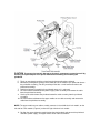
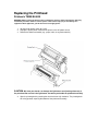
Replacing the Printhead
Printronix T5000/SL5000
WARNING Always unplug the printer power cord from the printer or power outlet before doing any
installation procedure. Failure to remove power could result in injury to you and damage the
equipment. When applicable, you will be instructed to apply power.
1. Set the printer power switch to O (Off).
2. Unplug the printer power cord from the printer or the AC power source.
3. Remove the ribbon and media (e.g., paper, label, or tag stock material).
CAUTION Oils from your hands can damage the light brown area (heating elements) of
the printhead. Do not touch the light brown area when you handle the printhead assembly.
4. Open the pivoting deck by rotating the deck lock lever fully clockwise. The pivoting deck
will swing upward, exposing the bottom of the printhead assembly.
CAUTION To prevent electrostatic damage to electronic components, ground yourself by
touching an unpainted part of the printer frame before handling and installing the
printhead.
5. Touch an unpainted part of the printer frame before touching the printhead.
6. Behind the pivoting deck, gently pull the lower tabs of the retainer clips upward to release
the printhead assembly. (You only need to pull the tabs a small amount to release the
printhead assembly.)
7. Hold the printhead assembly by the printhead cover as it is released.
8. Push the release tab down on the power supply cable assembly and remove the cable
from the printhead assembly.
9. Use the pull-tab to remove the printhead controller cable assembly from the printhead
assembly.
10. Push the release tab down on the upper media sensor cable assembly and remove the
cable from the printhead assembly.
NOTE: The upper media sensor cable assembly connects in the middle for 4 inch models, on the
left side for 6 inch models (Figure 8), and on the right side for 8 inch models.
11. Position the new printhead assembly below the pivoting deck and connect the printhead
controller, power supply, and upper media sensor cable assemblies.
NOTE: You may need to gently pull the lower tabs of the retainer clips upward to install the
printhead assembly.
12. Slide the printhead assembly upward into the pivoting deck until the retainer clips snap it
in place. Make sure that the cable assemblies do not extend past the printhead cover and
into the media or ribbon path.
Restore the Printer to Operation
1. Inspect the light brown area of the printhead for smudges or fingerprints. If necessary,
gently clean the light brown area with a soft, lint-free cloth (or a cotton swab) moistened
with isopropyl alcohol, or use a Cleaning Pen (P/N 203502-001).
2. Install the ribbon and media (e.g., paper, label, or tag stock material).
3. Close the pivoting deck and rotate the deck lock lever fully counterclockwise. (Figure 7.)
4. Close the media cover.
5. Plug the AC power cord into the printer and the power source.
6. Set the printer power switch to | (On).
7. Press Menu Button to place the printer in Menu mode.
8. Press the Enter and Down Arrow keys at the same time until “ENTER SWITCH
UNLOCKED” displays.
9. Press the Plus Button until “DIAGNOSTICS” displays.
10. Press Down Arrow Button until “DIAGNOSTICS/Reset Head Data” displays.
11. Press Enter Button to select “Reset Head Data.” The message “RESETTING/HEAD
DATA” displays. (This sets the Head Print Distance and Head On Time values to zero.)
12. Test printer operation and check print quality by selecting the Diagnostics Printer
Tests menu and printing one of the test patterns.