1
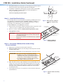
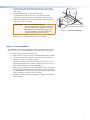
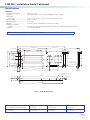
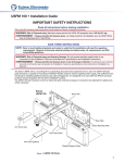
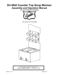
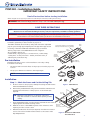
PCM 240 • Installation Guide
IMPORTANT SAFETY INSTRUCTIONS
Read all instructions before starting installation.
When using this accessory, basic precautions should always be followed, including the following:
WARNING: Risk of Personal Injury. Maximum setup load for the PCM is 50 lbs (22.7 kg).
SAVE THESE INSTRUCTIONS
NOTE: Refer to local building standards and codes to verify that the installation will meet the regulatory requirements.
Observe all local and national building and safety codes, UL requirements, and ADA accessibility guidelines.
WARNING: Risk of Personal Injury and property damage. Do not exceed specified weight limits of any component of
the installation. Follow the manufacturer's specifications and installation instructions.
The Extron PCM 240 Drop Ceiling Projector Mount is used for hanging
PoleVault® System AV products and various projectors.
The PCM is installed above the drop ceiling and secures the adjustable
pipe in a pass-through pipe adapter plate. The pipe then supports the
mounting of the Extron PMK 550 and UPB 25 projector bracket.
The key components of the PCM 240 are shown in figure 1.
Also included in the kit are:
4 turnbuckles, 5 lag eye bolts, 5 concrete anchors, 2 cable clamps,
1 safety wire – 15 feet, 2 tie wires – 30 feet, 4 T-frame screws, 4
adhesive pads, escutcheon ring.
1-gang and 2-gang Accessory Mounting
Points (for Power Sockets, for example)
Pipe
Adapter
Pipe Adapter Plate
Lock Nuts (4)
T-frame
Securing
Screws (4)
Pre-Installation
Pipe Adapter
Set Screws (2)
Determine the exact location of the installation on the drop ceiling.
Consider the following:
•
The vertical and horizontal offsets of the projector from the proposed
location.
•
The projector dimensions relative to the image target.
Base
Plate
NOTE: See the projector manual for details.
Installation
Step 1 — Mark the Frame and Cut the Ceiling Tile.
a.
At the location for the projector, identify the ceiling tile and T-frame
where the PCM will be installed.
Figure 1. PCM 240 Parts
b. Remove the predetermined ceiling tile and mark the maximum and
minimum throw distances of the projector on the T-frame (see
figure 2).
X"
Projector
Front
TIP: Mark the screen direction on the back of the tile to
help with orientation of the tile when replacing it after
cutting.
c.
Place the PCM base plate over the T-frame, between the two marks.
Lightly tighten the T-frame securing screws.
d. Mark the location of the PCM base plate on the T-frame to aid in
replacing it in the correct location.
e.
Measure the distances X and Y (see figure 2) from the inner vertical
section of the front and left T-frame runners to the center of the
Pipe Adapter Plate.
Y"
T-frame
Minimum and
Maximum
Throw Distance Marks
Figure 2. Minimum and Maximum
Throw Distances
1
PCM 240 • Installation Guide (Continued)
f.
Using these dimensions, mark and cut a hole (using a 2 inch hole saw) for
the projector pipe in the removed ceiling tile (see figure 3).
g. If required, to prepare the ceiling tile for a power outlet, use the PCM
plate to trace and cut out the 2-gang hole in the ceiling tile for a
UL approved RACO® junction box.
Top Side
If this is not required, proceed to step 3.
Underside
Step 2 — Install the Electrical Box.
The following method is recommended for integrating a RACO electrical box
(not supplied) on the PCM base plate. A RACO box (#8471), an MK box, or
standard UL electrical boxes can be inserted. Mounting holes for Extron
3 inch deep, ¼ rack wide devices are also included.
Figure 3. Mark and start cutting on
underside. Finish on top
side.
Install the RACO box on the PCM plate as follows:
a.
Attach the box to the plate, using the smallest notches in opposite corners
of the cut-out. Do not tighten the screws fully at this time.
3" Deep, ¼ Rack
Device Mounting Holes
b. On the room side of the tile, slide the plaster ring under the screws.
c.
Fully tighten the screws
WARNING: Risk of Personal Injury. For safety, complete all wiring
1-gang and 2-gang
Electrical Box Cut-outs
of the electrical boxes and accessories after the plate
is installed and secure.
All electrical installation should be done by a qualified
electrician.
Raco and MK Box Cut-out
Figure 4. RACO and MK Box
Installation Points.
Step 3 — Secure the PCM Base Plate to the Ceiling.
Tie wire installation
a.
Replace the cut ceiling tile, checking the orientation.
b. Replace the PCM base plate over the ceiling tile and align the hole with
the PCM adapter plate.
c.
Attach the four turnbuckles to the mounting plate, one at each corner.
ATTENTION: Risk of Personal Injury and property damage.
• DO NOT rest or lean on the mounting plate or
suspended ceiling when attaching the turnbuckles
and tie wire, or when drilling into the ceiling.
• For safest installation, insert the turnbuckle from
the outside so that it hooks inwards.
10
Attach turnbuckles
to long sides.
d. Mark and drill four holes, approximately 1¼ inch (32 mm) deep into the
ceiling joists, using a 1/4 inch (6.4 mm) diameter drill bit. Do this at 10
degrees out from vertical. Drill a fifth hole centered above the PCM for
the safety cable (see figure 5). Minimum suitable joist size should be
2 inches by 4 inches.
e.
Attach ceiling
anchors and wire
10 degrees from
vertical.
Mounting Plate
T-bar
Pipe Adapter Plate
Lock Nuts
T-bar Securing
Screws
Install appropriate anchors or lag eye bolts for the structural ceiling into
each drilled hole.
Figure 5. Attach Tie Wire and Safety
Cable.
2
f.
Loop the safety cable through the center anchor or lag eye bolt,
attach it to the plate center holes (figure 6) and secure it with the
cable clamps.
g. Cut appropriate lengths of the supplied tie wire.
Loop the wire through the anchors or lag eye bolts and the
turnbuckles, then twist the wire around itself at least five times.
h. Tighten the turnbuckles by hand (see figure 6), and level the plate
Secure PCM to frame
(from either side)
PCM
T-frame
so that it just rests on the grid.
ATTENTION: Potential Damage to Property.
• The four hanging wires should be taut, taking
the full weight of the completed installation.
• Overtightening the turnbuckles could cause
the T‑bar assembly to be lifted, making the
suspended ceiling bowed and unsafe.
j.
Adjust the turnbuckles to take
up any slack in the hanging wire.
Figure 6. Adjust the Turnbuckles.
Tighten the four T-frame securing screws on the PCM.
Step 4 — F
inal Installation.
The PCM 240 comes with a threaded pipe adapter installed in the adapter
plate. This allows for an Extron PMP projector mounting pole to be fitted.
To fit the mounting pole, do the following:
a.
Back out the set screws on the pipe adapter/adapter plate assembly.
b.
Screw the pole into the adapter. A minimum of three full turns is
required to safely secure the pole in place
c.
Secure the pole in place by tightening down the set screw on the
pipe adapter/adapter plate assembly. Cabling for the projector can
be accessed through the cut-out in the PMP pole.
d. Other optional accessories can also be installed at this point. These
include the Extron PMK 350, a low profile, two product mounting
kit, and the UPB 25, a Universal Projector Mounting Bracket suitable
for most projectors weighing up to 25 pounds.
e.
Complete any further device installation according to the relevant
device manual.
3
PCM 240 • Installation Guide (Continued)
Specifications
General
Maximum load capacity������������������ 50 lbs (22.7 kg)
Material����������������������������������������� Steel plate, Tie wire: steel, 14 AWG, 70,000 psi tensile strength
Dimensions
Base plate�������������������������������� 25.8” L x 8.0” W x 1.2” D (65.5 cm L x 20.3 cm W x 2.9 cm D)
Product weight������������������������������� 5.6 lbs (2.5 kg
Shipping weight����������������������������� 9 lbs (5 kg)
Vibration���������������������������������������� ISTA 1A in carton (International Safe Transit Association)
Regulatory compliance
Safety�������������������������������������� CE; c-UL, UL for use with UL Listed mount and projector; OSHPD anchorage pre-approval
Warranty���������������������������������������� 3 years parts and labor
NOTE: Specifications are subject to change without notice.
25.80 [655.32]
2X 14.612 [371.14]
2X .563 [14.288]
2.50 [63.51]
2X 8.500 [215.90]
4X Ø.19 [Ø4.78] THRU
2X .563 [14.288]
9.125 [231.78]
2X .50 [12.70]
2X 1.00 [25.40]
8.00 [203.20]
1.15 [29.21]
.60 [15.24]
3.00 [76.20]
2.00 [50.80]
2X 7.000 [177.800]
2X 6.00 [152.40]
6.80 [172.72]
2.00 [50.80]
2X 10-32 UNF - 2B
EXTRUDED .13 [3.18]
2X R1.063 [R26.99]
2X .12 [3.00]
4X R.107 [R2.71]
4X Ø.31 [Ø7.95] THRU
2X 11.187 [284.15]
2X 1.47 [37.33]
4.531 [115.09]
16.331 [414.80]
2X .39 [9.86]
BOTH SIDES
(1.13 [28.58])
3X .260 [6.604] X .500L [12.700]
OBROUND
23.40 [594.36]
2X 1.13 [28.58]
2X .70 [17.78]
2X 1.00 [25.40]
3X Ø.266 [Ø6.76] THRU
.14 [3.48]
23.67 [601.32]
Figure 7. PCM 240 Dimensions
Extron Headquarters
+1.800.633.9876 (Inside USA/Canada Only)
Extron Asia
+65.6383.4400
Extron China
+86.21.3760.1568)
Extron Korea
+82.2.3444.1571
Extron Europe
+31.33.453.4040
Extron Japan
+81.3.3511.7655
Extron Middle East
+971.4.2991800
Extron India
+91.80.3055.3777
© 2012 Extron Electronics — All rights reserved. All trademarks mentioned are the property of their respective owners. www.extron.com
4
68-1180-01
Rev D
08 12