1
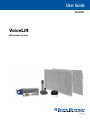
User Guide VoiceLift® VoiceLift Microphone System 68-1628-01 Rev. C 06 14 Safety Instructions Safety Instructions • English WARNING: This symbol, , when used on the product, is intended to alert the user of the presence of uninsulated dangerous voltage within the product’s enclosure that may present a risk of electric shock. ATTENTION: This symbol, , when used on the product, is intended to alert the user of important operating and maintenance (servicing) instructions in the literature provided with the equipment. For information on safety guidelines, regulatory compliances, EMI/EMF compatibility, accessibility, and related topics, see the Extron Safety and Regulatory Compliance Guide, part number 68-290-01, on the Extron website, www.extron.com. Instructions de sécurité • Français AVERTISSEMENT : Ce pictogramme, , lorsqu’il est utilisé sur le produit, signale à l’utilisateur la présence à l’intérieur du boîtier du produit d’une tension électrique dangereuse susceptible de provoquer un choc électrique. ATTENTION :Ce pictogramme, , lorsqu’il est utilisé sur le produit, signale à l’utilisateur des instructions d’utilisation ou de maintenance importantes qui se trouvent dans la documentation fournie avec le matériel. Pour en savoir plus sur les règles de sécurité, la conformité à la réglementation, la compatibilité EMI/EMF, l’accessibilité, et autres sujets connexes, lisez les informations de sécurité et de conformité Extron, réf. 68-290-01, sur le site Extron, www.extron.com. Sicherheitsanweisungen • Deutsch WARNUNG: Dieses Symbol auf dem Produkt soll den Benutzer darauf aufmerksam machen, dass im Inneren des Gehäuses dieses Produktes gefährliche Spannungen herrschen, die nicht isoliert sind und die einen elektrischen Schlag verursachen können. VORSICHT: Dieses Symbol auf dem Produkt soll dem Benutzer in der im Lieferumfang enthaltenen Dokumentation besonders wichtige Hinweise zur Bedienung und Wartung (Instandhaltung) geben. Weitere Informationen über die Sicherheitsrichtlinien, Produkthandhabung, EMI/EMF-Kompatibilität, Zugänglichkeit und verwandte Themen finden Sie in den Extron-Richtlinien für Sicherheit und Handhabung (Artikelnummer 68-290-01) auf der Extron-Website, www.extron.com. Instrucciones de seguridad • Español ADVERTENCIA: Este símbolo, , cuando se utiliza en el producto, avisa al usuario de la presencia de voltaje peligroso sin aislar dentro del producto, lo que puede representar un riesgo de descarga eléctrica. ATENCIÓN: Este símbolo, , cuando se utiliza en el producto, avisa al usuario de la presencia de importantes instrucciones de uso y mantenimiento recogidas en la documentación proporcionada con el equipo. Para obtener información sobre directrices de seguridad, cumplimiento de normativas, compatibilidad electromagnética, accesibilidad y temas relacionados, consulte la Guía de cumplimiento de normativas y seguridad de Extron, referencia 68-290-01, en el sitio Web de Extron, www.extron.com. Инструкция по технике безопасности • Русский ПРЕДУПРЕЖДЕНИЕ: Данный символ, , если указан на продукте, предупреждает пользователя о наличии неизолированного опасного напряжения внутри корпуса продукта, которое может привести к поражению электрическим током. ВНИМАНИЕ: Данный символ, , если указан на продукте, предупреждает пользователя о наличии важных инструкций по эксплуатации и обслуживанию в руководстве, прилагаемом к данному оборудованию. Для получения информации о правилах техники безопасности, соблюдении нормативных требований, электромагнитной совместимости (ЭМП/ЭДС), возможности доступа и других вопросах см. руководство по безопасности и соблюдению нормативных требований Extron на сайте Extron: www.extron.com, номер по каталогу - 68-290-01. Chinese Simplified(简体中文) 警告: 产品上的这个标志意在警告用户该产品机壳内有暴露的危险 电压, 有触电危险。 注 意: 产 品 上 的 这个 标 志 意 在 提 示用 户 设 备 随 附 的 用 户 手 册 中 有 重要的操作和维护(维修)说明。 关于我们产品的安全指南、遵循的规范、EMI/EMF 的兼容性、无障碍 使用的特性等相关内容,敬请访问 Extron 网站 www.extron.com,参见 Extron 安全规范指南,产品编号 68-290-01。 Chinese Traditional( ) 警告: 若產品上使用此符號,是為了提醒使用者,產品機殼內存在著 可能會導致觸電之風險的未絕緣危險電壓。 注意 若產品上使用此符號,是為了提醒使用者,設備隨附的用戶手冊中有重 要的操作和維護(維修)説明。 有關安全性指導方針、法規遵守、EMI/EMF 相容性、存取範圍和相關主題的詳細資 訊,請瀏覽 Extron 網站:www.extron.com,然後參閱《Extron 安全性與法規 遵守手冊》,準則編號 68-290-01。 Japanese 警告: この記号 が製品上に表示されている場合は、筐体内に絶縁されて いない高電圧が流れ、感電の危険があることを示しています。 注意: この記号 が製品上に表示されている場合は、本機の取扱説明書 に 記載されている重要な操作と保守(整備)の指示についてユーザーの 注 意を喚起するものです。 安全上のご注意、法規厳守、EMI/EMF適合性、その他の関連項目に ついては、エクストロンのウェブサイト www.extron.com より『Extron Safety and Regulatory Compliance Guide』(P/N 68-290-01) をご覧ください。 Korean 경고: 이 기호 가 제품에 사용될 경우, 제품의 인클로저 내에 있는 접지되지 않은 위험한 전류로 인해 사용자가 감전될 위험이 있음을 경고합니다. 주의: 이 기호 가 제품에 사용될 경우, 장비와 함께 제공된 책자에 나와 있는 주요 운영 및 유지보수(정비) 지침을 경고합니다. 안전 가이드라인, 규제 준수, EMI/EMF 호환성, 접근성, 그리고 관련 항목에 대한 자세한 내용은 Extron 웹 사이트(www.extron.com)의 Extron 안전 및 규제 준수 안내서, 68-290-01 조항을 참조하십시오. FCC Class A Notice This equipment has been tested and found to comply with the limits for a Class A digital device, pursuant to part 15 of the FCC rules. The Class A limits provide reasonable protection against harmful interference when the equipment is operated in a commercial environment. This equipment generates, uses, and can radiate radio frequency energy and, if not installed and used in accordance with the instruction manual, may cause harmful interference to radio communications. Operation of this equipment in a residential area is likely to cause interference. This interference must be corrected at the expense of the user. NOTE: For more information on safety guidelines, regulatory compliances, EMI/EMF compatibility, accessibility, and related topics, see the “Extron Safety and Regulatory Compliance Guide” on the Extron website. Copyright © 2014 Extron Electronics. All rights reserved. Trademarks All trademarks mentioned in this guide are the properties of their respective owners. The following registered trademarks, registered service marks, and trademarks are the property of RGB Systems, Inc. or Extron Electronics: Registered Trademarks (®) AVTrac, Cable Cubby, CrossPoint, eBUS, EDID Manager, EDID Minder, Extron, Flat Field, GlobalViewer, Hideaway, Inline, IP Intercom, IP Link, Key Minder, LockIt, MediaLink, PlenumVault, PoleVault, PowerCage, PURE3, Quantum, SoundField, SpeedMount, SpeedSwitch, System INTEGRATOR, TeamWork, TouchLink, V‑Lock, VersaTools, VN‑Matrix, VoiceLift, WallVault, WindoWall, XTP, and XTP Systems Registered Service Mark(SM) : S3 Service Support Solutions Trademarks (™) AAP, AFL (Accu‑Rate Frame Lock), ADSP (Advanced Digital Sync Processing), Auto‑Image, CableCover, CDRS (Class D Ripple Suppression), DDSP (Digital Display Sync Processing), DMI (Dynamic Motion Interpolation), Driver Configurator, DSP Configurator, DSVP (Digital Sync Validation Processing), EQIB, FastBite, FOXBOX, Global Configurator, IP Intercom HelpDesk, MAAP, MicroDigital, ProDSP, QS-FPC (QuickSwitch Front Panel Controller), Scope‑Trigger, SIS, Simple Instruction Set, Skew‑Free, SpeedNav, Triple‑Action Switching, XTRA, ZipCaddy, ZipClip Conventions Used in this Guide Notifications The following notifications are used in this guide: CAUTION: Risk of minor personal injury. ATTENTION : Risque de blessure mineure. ATTENTION: • Risk of property damage. • Risque de dommages matériels. NOTE: A note draws attention to important information. Software Commands Commands are written in the fonts shown here: ^AR Merge Scene,,Op1 scene 1,1 ^B 51 ^W^C [01] R 0004 00300 00400 00800 00600 [02] 35 [17] [03] E X! *X1&* X2)* X2#* X2! CE} NOTE: For commands and examples of computer or device responses mentioned in this guide, the character “0” is used for the number zero and “O” is the capital letter “o.” Computer responses and directory paths that do not have variables are written in the font shown here: Reply from 208.132.180.48: bytes=32 times=2ms TTL=32 C:\Program Files\Extron Variables are written in slanted form as shown here: ping xxx.xxx.xxx.xxx —t SOH R Data STX Command ETB ETX Selectable items, such as menu names, menu options, buttons, tabs, and field names are written in the font shown here: From the File menu, select New. Click the OK button. Specifications Availability Product specifications are available on the Extron website, www.extron.com. Contents Introduction.................................................... 1 SIS Configuration and Control................... 25 About this Guide.................................................. 1 About the VoiceLift System.................................. 1 System Components....................................... 1 Features.......................................................... 2 Application Diagrams........................................... 3 Overview........................................................... 25 Host to Receiver Communications..................... 25 Receiver-initiated Messages.......................... 26 Error Response.............................................. 26 Timeout......................................................... 26 Commands and Responses.............................. 26 Using the Command and Response Table..... 26 Symbol Definitions......................................... 27 Command and Response Table for SIS Commands...................................................... 28 Features and Operation................................ 5 Functional Overview of the VoiceLift System........ 5 Cable Length................................................... 7 Charging Station.................................................. 7 Microphones....................................................... 8 Pendant Microphone....................................... 8 Handheld Microphone................................... 11 Installing or Replacing the Microphone Battery......................................................... 13 Charging the Microphone Battery.................. 14 Setting Up and Using the Microphones.......... 16 Adjusting the Microphone Volume.................. 17 Tips for Using the Microphones..................... 18 Receiver............................................................ 19 Integrated DSP.............................................. 19 Receiver Dome and Base Plate..................... 20 Receiver Housing and Back Plate.................. 22 Removing and Replacing the Receiver Dome........................................................... 23 Special Application: Instant Alert.............. 30 Installing the Receiver (Overview)............. 34 Planning the Installation ................................... 34 Installation Overview.......................................... 36 Stage 1: Installing the Receiver Base and Housing........................................................ 36 Stage 2: Installing the FF 120 Speakers ........ 37 Stage 3: Installing the PoleVault Switcher....... 38 Stage 4: Connecting the Cables.................... 38 Stage 5: Setting Up the Microphone and Testing the System....................................... 38 Reference Information: Updating the Firmware....................................................... 39 Downloading a Firmware File............................. 39 Updating Firmware Using Firmware Loader....... 41 VoiceLift System • Contents v VoiceLift System • Contents vi Introduction This section gives an overview of the VoiceLift System, listing its components and features. Topics include: • About this Guide • About the VoiceLift System • Application Diagrams About this Guide This guide discusses the components and operation of the Extron VoiceLift System. For details on installation procedures, see the VoiceLift System Installation Guide, delivered with your VoiceLift System. The following terms are used in this guide: • “VoiceLift System” refers to the entire system, which includes the pendant or handheld microphones, the receiver, and the charging station. • “Receiver” refers to the VLR 102 infrared (IR) receiver, which mounts onto a wall or ceiling. • “Charging station” refers to the VLC 202 charger for the microphone. • “Microphone” refers to the VLP 202 pendant or the VLH 102 handheld microphone. About the VoiceLift System The VoiceLift System is a low-power classroom microphone amplification system (also referred to as a “soundfield system”) that enables an instructor or presenter to be clearly heard at a comfortable level throughout the entire room. System Components • Microphone (VLP 202 or VLH 102) — The pendant microphone (VLP 202) is worn by the instructor or presenter on a lanyard around the neck, but can also be handheld or clipped to clothing if desired. The handheld microphone (VLH 102) cannot be worn on a lanyard. Each microphone features volume control, a power switch, and an auxiliary line input connector to feed in a source (such as an MP3 player). For detailed descriptions of the two VoiceLift microphones, see Microphones on page 8. • Receiver (VLR 102) — The receiver is the main sensor for the VoiceLift System. It features the following: • Captive screw connectors for auxiliary input, RS-232, contact input, and relay output • RJ-45 connectors for power, communication with the PoleVault switcher/amplifier, and audio output • Two DIP switches that control the volume change tone and the auxiliary input mode VoiceLift System • Introduction 1 • Charging station (VLC 202) — The optional microphone charging stations contain slots in which one or two microphones can be placed for their batteries to be recharged. The charging stations are powered by an external power supply. • Lightweight microphones — The pendant and handheld microphones are made of lightweight and impact-resistant polycarbonate material. The pendant microphone can comfortably be worn around the neck or clipped to clothing. • Built-in DSP feedback suppression — The receiver has an integrated digital signal processor (DSP) that suppresses feedback while maximizing sound quality and intelligibility. The DSP prevents ringing caused by frequencies cycling out of control through the microphone and speakers. • Two microphones per classroom — The VoiceLift System supports up to two pendant microphones, or one pendant and one handheld microphone, in each classroom. The pendant microphone can be used by instructors and students. • Power (Mute) buttons — The microphones contain easily accessible buttons on the sides or front to mute the sound and power the microphone on and off. • Volume buttons — On the pendant microphone (normally used by the instructor or presenter), a Volume button is conveniently located on the side, enabling the instructor to easily raise and lower the volume during a presentation. Features On the handheld microphone (normally used by the student), Volume Up and Down buttons are located behind the battery cover. These buttons can be used to set the volume prior to use but cannot be accidentally pressed during the presentation. • Instant alert e-mail messaging — The VoiceLift receiver can be wired to enable the instructor to send e-mail alerts by pressing the microphone Volume button when assistance is required. • Auxiliary line input — An auxiliary input connector on the microphone enables input from an MP3 player or other source. • Battery power — The VLP 202 and VLH 102 microphones are each powered by a single NiMh or alkaline AA battery. NiMh batteries can be recharged via the VLC 102 or VLC 202 charging station or by a wall charger. • Charging station — The VLC 202 desktop charging station holds and recharges up to two VoiceLift microphones simultaneously. • Mounting options — The VLR 102 receiver is compact and can be mounted on a wall or ceiling, or to a junction box. VoiceLift System • Introduction 2 Application Diagrams The following diagrams show possible installations of a VoiceLift System. FF 120 Speakers Free GlobalViewer Software VoiceLift Receiver TCP/IP Network CONFIG 1 INPUT 2 SELEC TION 3 4 5 AUX INPUT AUDIO AUDIO PEAK NORMAL SIGNAL PVS LEVEL POLEVA MIC 305S ADJUS ULT PEAK VOICELIFT T NORMAL SIGNAL A IP SWITCH ER PAGING SENSOR SENSITI VITY PVS 305SA IP PoleVault Switcher / Amplifier 1 O VoiceLift Pendant Microphone VIDE Y LA 2 SP DI X O AU VIDE F OF 3 ON PC ME LU VO G NFI CO E AG IM E MUT 4 4 IP MLC Plus 10 MLC 104 IP Plus MediaLink Controller Figure 1. VoiceLift System Diagram VoiceLift System • Introduction 3 MmZz Ll Kk XxYy Jj Ii Ww h H v Gg u V Ff t U Ee s T Dd Rr S c q C Bb p Q Aa Oo P Nn Extron VLR 102 Receiver Extron FF 120T Plenum Flat Field Speakers Extron VLP 202 Extron Pendant Microphone Extron VLH 102 CONFIG Handheld VoiceLift Microphone 1 INPUT 2 SELECTION 3 4 5 AUX INPUT AUDIO AUDIO CLIP NORMAL SIGNAL LEVEL POLEVAULT PVS MIC ADJUST 305SA SWITCHER CLIP VOICELIFT NORMAL SIGNAL PAGING SENSOR SENSITIVITY Extron PVS 305SA IP Amplifier Extron VLC 202 Desktop Charging Station Figure 2. VoiceLift System in a Classroom Using a VLH 102 Handheld Student Microphone VoiceLift System • Introduction 4 Features and Operation This section provides an overview of the VoiceLift System and detailed descriptions of each component and its function. Topics include: • Functional Overview of the VoiceLift System • Charging Station • Microphones • Receiver Functional Overview of the VoiceLift System The VoiceLift System functions as follows: The VLP 202 Pendant Microphone or the VLH 102 Handheld Micropnone picks up speech and transmits it via an IR signal to the VLR 102 IR Receiver. The receiver transmits the signal to a PoleVault switcher that functions as an amplifier and also powers speakers placed throughout the room. Figure 3 on the next page shows the path of the audio signal through the VoiceLift System. VoiceLift System • Features and Operation 5 FIG_Audio signal path VLP 202 Pendant Microphone or VLH 102 Handheld Microphone OUT IN 2 CTS-2 O 1 N RS-232 Tx Rx TONE MIX AUX IN + CTC IN RLY NO C MLC Controller Connection VLR 102 Receiver To Speakers PoleVault Switcher N15779 1A RGB 2A RGB 3A RGB 4A RGB ® LISTED POWER 12V 5A MAX I N P U T S OUTPUTS RGB 1B RGB Figure 3. 2B RGB 3B RGB /VIDEO 4B RGB /VIDEO VIDEO US LINE OUT 17TT AUDIO/VIDEO APPARATUS VOICELIFT RECEIVER L R L R AUX AUDIO INPUT 5 AMPLIFIED AUDIO OUT DO NOT GROUND OR SHORT 2/4/8 SPEAKER Ohms OUTPUTS L R CLASS 2 WIRING 10V 50mA LAN 3 LAN 4 LAN 1 LAN 2 CONTROL Tx Rx IR 12V PAGING RS-232 MLC/IR SENSOR VOL/MUTE VoiceLift System Connections and Audio Signal Path A Microphone — The VLP 202 Pendant Microphone or the VLH 102 Handheld Microphone picks up speech from the instructor and transmits a mono audio signal via infrared (IR) on the selected channel (2.3 MHz or 2.8 MHz). B Receiver — The VLR 102 receiver picks up the IR signal from the microphone. The receiver outputs a balanced -10 dBV line level signal via an RJ-45 connector. The signal passes to the PoleVault switcher through a shielded twisted pair (STP) cable. C PoleVault switcher — The PoleVault switcher also functions as an amplifier for the VoiceLift System. It receives the audio signal from the VLR 102 receiver, amplifies it, and sends it to strategically placed speakers. The switcher powers speakers placed throughout the room to improve the signal-to-noise ratio of the voice of the speaker to at least +15 dB. VoiceLift System • Features and Operation 6 Cable Length The length of the cable from the receiver to the PoleVault switcher can be: Minimum: 5 feet (1.5 meters) Maximum: 40 feet (10.2 meters) Charging Station The VLC 202 charging station recharges the microphone battery. The charger contains two slots, enabling two microphones to be charged simultaneously. The charging station is powered by an external wall power supply (provided). Figure 4. VLC 202 Charging Station The VLC 102 and VLC 202 charging stations have the following connections: A DC power jack — Plug the 5 VDC, 1 A wall charger from a 110-130 VAC (U.S.) or XX-240 VAC (international) into this coaxial center positive DC jack to provide power to the charging station. B Microphone slots — Insert one or two microphones into these slots to charge their batteries. Each slot contains two charging contacts that mate with the two charging contacts on the bottom panel of the microphone. When two microphones are in the charging station, each is charged independently of the other, and the two can finish charging at different times. ATTENTION: • Do not charge alkaline batteries. • Ne rechargez pas les piles alkalines. For charging status, check the microphone power LED (see Microphones on the next page for the LED location on each microphone). VoiceLift System • Features and Operation 7 Microphones Pendant Microphone The VoiceLift VLP 202 pendant microphone operates via IR at two frequencies: 2.3 MHz on channels A and C, and 2.8 MHz on channels B and D. The microphone picks up speech and transmits a signal wirelessly to the VLR 102 receiver. The microphone is powered by one AA battery (provided), which can be recharged using the VLC 202 charging station. ATTENTION: • Do not charge alkaline batteries. • Ne rechargez pas les piles alkalines. The VLP 202 pendant microphone has the following controls and connections: Front, side, and top panels Figure 5. VLP 202 Pendant Microphone Front and Side Panels A Pwr LED — This bicolor LED indicates the microphone power, volume, and charging status as follows: When the microphone is in use: LED Color Indication Green – steady Power is on, microphone is functioning. Green – flashing Volume button is being pressed (volume is changing). Red – flashing Low battery (1 hour or less of talk time left) VoiceLift System • Features and Operation 8 When the microphone is charging: LED Color Indication Red – steady Battery is charging. Green – steady Battery is fully charged. Red and green – flashing Alkaline or damaged battery is detected. B Microphone acoustic port — The microphone receives the audio signals via this port. Do not block this port while the microphone is in use. C Audio input port (Audio In) — Connect an MP3 player or other audio device to this 3.5 mm TRS jack for auxiliary audio line input. When a device is plugged into this port, its audio is mixed with the internal microphone. NOTE: Because the audio input is mixed with the microphone input, pressing the Volume button on the microphone affects the volume of the audio input device. However, it is recommended that you use the volume control of the input device instead of the microphone Volume button to adjust the levels of this audio input. TRSTBL Tip (+) Ring (-) Sleeve ( ) Figure 6. Pin Signal Tip Left channel Ring Right channel Sleeve Ground 3.5 mm TRS Connector for Use with the Audio Input Port D Volume button — This rocker button, containing raised arrows, raises and lowers the microphone volume (see Adjusting the Microphone Volume on page 17). This button can also be used to send an IR signal to the receiver to close its relay (Rly) port in order to trigger an alert (see G Relay (Rly) port on page 21 and the Special Application: Instant Alert section beginning on page 30 for more information on this function.) E Battery compartment cover — Slide this cover down to access the battery compartment and Volume buttons. F Battery compartment — Insert one AA NiMh (provided) or alkaline battery into this compartment, aligning the + and – poles as indicated inside the compartment. NiCd batteries can be used but cannot be charged from a VoiceLift charging station. Li-ion batteries are not supported. ATTENTION: • Do not charge alkaline batteries. • Ne rechargez pas les piles alkalines. G Power and mute switch (Off/Mute/On) — Slide this switch up to power on the microphone. Slide it down to power off or mute the microphone. NOTE: Always slide this switch to Off before charging the microphone. VoiceLift System • Features and Operation 9 Back panel Figure 7. VLP 202 Pendant Microphone Back Panel A Clip — Use this clip to attach the VLP 202 to clothing or to a lanyard (included). See Setting Up and Using the Microphones on page 16 to attach the lanyard. The provided lanyard features: • A lanyard lock to retain adjustments to the position of the microphone clipped to the lanyard. • A breakaway clasp that separates and releases the lanyard from around the neck if it is pulled tight. Place this clasp at the back of your neck when wearing the pendant microphone. B Channel selection switch — Use a small screwdriver to turn this rotary switch to select channel A, B, C, or D when setting up the microphone. Primary channels A (2.3 MHz) and B (2.8 MHz) are for use by the instructor or speaker. Secondary channels C (2.3 MHz) and D (2.8 MHz) are intended for use by the students. The secondary channels operate the same as channels A and B, but the microphone Volume button is disabled. A B C D NOTE: When two microphones are used, they must be on different frequencies. Only channels A and B, A and D, B and C, or C and D can be used together. C Microphone labels — Place the appropriate provided sticker in this space to identify the microphone or the user for whom the microphone has been set up (see Setting Up and Using the Microphones). VoiceLift System • Features and Operation 10 Handheld Microphone The VLH 102 Handheld Microphone can be used with the VoiceLift System as an alternative to the VLP 202 Pendant Microphone. The VLH 102 is best used as a pass-around microphone for student presentations or a secondary microphone for team teaching and guest speakers. The handheld microphone has many of the features of the pendant microphone, including a power switch and an auxiliary input jack to allow playback from audio devices through the system. It is powered by one AA NiMh (provided) or alkaline battery. NiMh batteries can be recharged using the VLC 202 charging station or an external wall charger. ATTENTION: • Do not charge alkaline batteries. • Ne rechargez pas les piles alkalines. The VLH 102 provides two channels: channel A at 2.3 MHz and channel B at 2.8 MHz. Unlike the VLP 202, it does not provide channels C and D for disabling the volume control on the student microphone. A E B F HRG AUDIO IN D R WE PO C I G A B VOLUME H Figure 8. VLH 102 Handheld Microphone A Microphone grille — Covers and protects the microphone acoustic port, through which the VLH 102 receives audio signals. Do not block this grille while the microphone is in use. B Power LED — This bicolor LED, located above the Power switch, indicates the microphone power, volume, and charging status as follows: When the microphone is in use: LED Color Indication Green – steady Power is on, microphone is functioning. Green – flashing Volume button is being pressed (volume is changing). Red – flashing Low battery (1 hour or less of talk time is left.) VoiceLift System • Features and Operation 11 When the microphone is charging: LED Color Indication Red – steady Battery is charging. Green – steady Battery is fully charged. Red and green – flashing Alkaline or damaged battery is detected. C Power switch — Slide this switch up to power on the microphone and down to power off or mute the microphone. NOTE: Always slide this switch to Off before charging the microphone. D Audio input port (Audio In) — Connect an MP3 player or other audio device to this 3.5 mm TRS jack for auxiliary audio line input. When a device is plugged into this port, its audio is mixed with the signal from the internal microphone. NOTE: Because the audio input is mixed with the microphone, pressing the Volume buttons on the microphone affects the volume of the audio input device. However, it is recommended that you use the volume control of the input device instead of the microphone Volume buttons to adjust the levels of this audio input. Tip (+) Ring (-) TRS Signal Tip Left channel Ring Right channel Sleeve Ground Sleeve ( ) Figure 9. 3.5 mm TRS Connector for Audio Input Port E Charging (Chrg) jack — Connect the wall charger (5 VDC, 1 A) into this DC coaxial jack to charge the microphone battery, as an alternative to the charging station. A full charge can take up to 5 hours. Always turn the microphone off before charging it. F Battery compartment — Insert one AA NiMh (provided) or alkaline battery into this compartment, aligning the + and – poles as indicated inside the compartment. NiCd batteries can be used, but cannot be charged from the microphone. Li-ion batteries are not supported. G Battery compartment cover — Remove this cover to access the battery and the volume buttons (see Installing or Replacing the Microphone Battery on page 13). H Volume buttons (inside the battery compartment) — These buttons, marked with > and <, raise and lower the microphone volume (see Handheld microphone volume adjustment on page 18). To access these buttons, remove the battery cover Tip (+) (see Installing or Replacing the Microphone Battery). Ring (-) NOTE: You can disable the tone by setting the Tone DIP switch on the receiver to Off (see C DIP switches on page 21). Pressing and holding both of these buttons simultaneously for 3 seconds sends an Sleeve (to )close its relay (Rly) port. This is typically used to trigger an IR signal to the receiver alert (see G Relay (Rly) port on page 21 and the Special Application: Instant Alert section beginning on page 30 for more information on this function). VoiceLift System • Features and Operation 12 I Channel selection switch — When setting up the microphone, use a small screwdriver to turn this rotary switch so that its arrow points to channel A (2.3 MHz) or B (2.8 MHz). You must remove the battery cover to access this switch. NOTE: When two microphones are used, they must be on different frequencies; in other words, one must be set to channel A and the other to B. A B Installing or Replacing the Microphone Battery A rechargeable AA NiMh battery is provided for each microphone in your system. You can also use an AA alkaline battery. Additional replacement batteries can be purchased locally. To install or replace the battery: 1. Remove the battery cover. • Pendant microphone: Slide the cover downward until its two tabs are free of their slots and lift the cover off. • Handheld microphone: a. Slide the battery cover downward until it stops. b. Lift the cover up and off the microphone. Positive Terminal A B VOLUME VLP 202 VLH 102 Figure 10. Removing the Microphone Battery Covers 2. Place the battery in the compartment, aligning the + and – poles as indicated inside the compartment (the positive terminal is at the bottom). 3. Replace the battery cover. • Pendant microphone: a. Place the cover onto the microphone so that the battery is covered. b. Slide the cover upward until the two tabs at the top of the cover snap into the slots on the microphone. VoiceLift System • Features and Operation 13 Handheld microphone: • a. Align the tabs on both sides of the cover with the two slots on the outer edges near the bottom of the microphone (see the illustration at right). b. Press the cover until the tabs snap into the slots. c. Slide the cover upward into place (you may need to press firmly). A B Charging the Microphone Battery VOLUME The microphones can be charged by the following methods: • In the VLC 202 charging station • Using the provided wall charger (VLH 102 only) Slots Using the charging station The VLC 202 charging station provides a convenient way to charge the microphone battery overnight or between uses. The charging station can charge two microphones simultaneously, and the microphones can start and finish charging at different times. The microphone battery requires up to 5 hours to charge fully in order to provide a full day of use. It is safe to charge for extended periods, such as winter or spring breaks. However, it is recommended that you store the microphone out of the charger. CAUTION: Do not replace the battery with an incorrect type. Use only NiMh or alkaline batteries. ATTENTION : Ne pas remplacer la pile par le mauvais type de pile. Utilisez seulement des piles de type NiMh ou alkaline. ATTENTION: • Do not recharge alkaline batteries. • Ne rechargez pas les piles alkalines. • Dispose of used batteries according to the instructions provided on the battery packaging. • Débarrassez-vous des piles utilisées selon les instructions du fabricant. To charge the microphone using the charging station: 1. Turn off the microphone by sliding the power switch to Off. NOTE:The microphone should be turned off before charging. However, if it is inadvertently left on, the microphone continues to charge, but at a slower rate. If the microphone is on when placed in the charger, its power LED lights red. PW R ON ron Ex OFF/MUTE OFF/MUTE n ON tro VLP 202 VLH 102 Figure 11. Sliding the Microphone Power Switch to Off VoiceLift System • Features and Operation 14 2. Plug the wall charger cable into a 110-130 VAC (U.S.) or XX-240 VAC (international) power source (see figure 12). 3. Connect the charger cable to the charging station power jack. Figure 12. Wall Charger Cable and Charging Station Power Jack 4. Place the microphone in one of the slots in the charging station, with the charging contacts on the bottom of the microphone facing down. Charge until the Pwr LED lights green (this takes up to 5 hours). PW R Charging Contacts on Pendant Microphone Bottom Panel Ex OFF/MUTE n ON tro Charging Contacts on Handheld Microphone Bottom Panel Figure 13. Charging Contacts on the Microphones Using the wall charger — VLH 102 only An alternative method of charging the handheld microphone is to plug the provided wall charger into a 110-130 VAC (U.S.) or XX-240 VAC (international) power outlet, and connect its cable to the microphone Charge jack as shown in figure 14. Charge until the Pwr LED lights green (this takes up to 5 hours). Wall Charger Power LED VLH 102 Figure 14. Connecting the Wall Charger to the Handheld Microphone VoiceLift System • Features and Operation 15 Setting Up and Using the Microphones Follow these steps to set up the VLP 202 Pendant Microphone or the VLH 102 Handheld Microphone and use it in a classroom: 1. Set the channels on the instructor and student (if applicable) microphones, using the rotary switch (located on the back of the VLP 202 below the product label and behind the battery cover of the VLH 102). Channels A and C are at 2.3 MHz, and channels B and D are at 2.8 MHz. (The VLH 102 has only channels A and B.) NOTE:Each microphone in the system must be set to a different frequency. For example, on the pendant microphone A and B, A and D, B and C, or C and D can be used together. If the students will use a pendant microphone, it is recommended that the channel be set to C or D. On these channels, the Volume button is disabled, and the student is not able to inadvertently reset the volume. 2. Apply the appropriate label sticker to the microphone. For example, if your microphones have been set to channels A and B, place the Mic 1 (red) label on the microphone that is using channel A. Place the Mic 2 label (green) on the microphone using channel B. NOTE: A recessed space is provided on the back of the pendant microphone, below the channel adjustment switch. No location is specified for the handheld microphone. Teacher Mic 1 Student Mic 2 33-1694-01 A 08 08 3. Verify that the battery is installed (see Installing or Replacing the Microphone Battery on page 13) and charged (see Charging the Microphone Battery on page 14). 4. (Pendant microphone only) Attach the lanyard (provided) to the microphone clip (A) and place the lanyard around your neck. The microphone should hang approximately 4 inches (10.2 cm) below your chin. Use the lanyard cord lock (B) to make adjustments to the length. Figure 15. Using the Lanyard with the Microphone 5. Turn the microphone power on by sliding the power switch up to the On position. 6. Speak in a normal tone of voice. If necessary, adjust the volume level (see “Adjusting the Microphone Volume”). VoiceLift System • Features and Operation 16 7. When finished, or at the end of the day, turn the microphone off by sliding the power switch down to the Off position. 8. Return the microphone to the charging station or connect it to the wall charger. Make sure that the microphone is turned off before charging it. ATTENTION: • Do not charge alkaline batteries. • Ne rechargez pas les piles alkalines. Adjusting the Microphone Volume Pendant microphone volume adjustment To adjust the volume on the VLP 202 Pendant Microphone, use the Volume rocker button on the left side as follows: • Press the top section of the button (marked with a raised >) to raise the volume. • Press the bottom section of the button (marked with a raised <) to lower the volume. Up > Down Figure 16. Adjusting the Volume on the Pendant Microphone When this button is pressed, the receiver produces a tone and the Pwr LED blinks. NOTES: • You can disable the tone by setting the Tone DIP switch on the receiver to Off (see C DIP switches on page 21). • Volume adjustment works only for microphones set to channel A or B (see figure 17). Channel Switch Figure 17. Channel Switch on the VLP 202 Pendant Microphone VoiceLift System • Features and Operation 17 Handheld microphone volume adjustment To adjust the volume on the VLH 102 Handheld Microphone: 1. Remove the battery cover (see Installing or Replacing the Microphone Battery on page 13 for the procedure). 2. Press the Up (>) or Down (<) button, located below the battery compartment, to raise or lower the volume. A B VOLUME A B VOLUME Figure 18. Volume Buttons on the Handheld Microphone 3. Replace the battery cover (see Installing or Replacing the Microphone Battery). Tips for Using the Microphones • Speak in a normal tone of voice. When the microphone is set properly, your voice is amplified above ambient room noise. • Turn the microphone off while having private conversations. • Charge the microphone battery every night. A fully charged battery will last the entire school day. NOTE: Always turn the microphone off before charging. • If you are experiencing intermittent audio problems: • Check the batteries and replace them if necessary. NiMH and alkaline batteries are supported. CAUTION: Do not replace the battery with an incorrect type. Use only NiMh or alkaline batteries. ATTENTION : Ne pas remplacer la pile par le mauvais type de pile. Utilisez seulement des piles de type NiMh ou alkaline. ATTENTION: • Do not recharge alkaline batteries. • Ne rechargez pas les piles alkalines. • Dispose of used batteries according to the instructions provided on the battery packaging. • Débarrassez-vous des piles utilisées selon les instructions du fabricant. Do not set more than one microphone to the same channel in a system. • Make sure there are no obstructions between the microphone and the receiver. VoiceLift System • Features and Operation 18 Receiver The VoiceLift VLR 102 Receiver receives infrared signals from the VoiceLift VLP 202 Pendant Microphone. The receiver outputs a balanced -10 dBV line level signal via an RJ-45 connector. Ceiling Tile Cables Housing and Base Plate Base Plate with Connectors Dome Figure 19. The VLR 102 Receiver Integrated DSP Digital signal processing (DSP) is a specialized circuit that processes audio signals that have been converted to digital form. The VLR 102 Receiver has a built-in DSP that suppresses feedback while maximizing sound quality and intelligibility. As feedback occurs, up to 15 dynamic filters engage, automatically detecting and eliminating unwanted feedback frequencies. The dynamic filters are notch filters, providing up to 30 dB of attenuation for feedback frequencies caused by high microphone levels, room resonance, or proximity of the microphone to a speaker. The DSP retains a maximum of 10 filters. After a period of 2 minutes, if the number of filters is greater than 10, the oldest filters begin to slowly release until the number of dynamic filters in use equals 10. This process assures that five filters are always available in case of unexpected feedback (see the VoiceLift System Installation Guide to set the dynamic filters). VoiceLift System • Features and Operation 19 Receiver Dome and Base Plate The tinted sensor dome filters ambient light but lets the IR signals from the microphone pass through to the sensors. The dome is attached to the receiver base plate by four tabs that are inserted into slots on the base plate. H IN A OUT B AUX IN + RS-232 Tx Rx O 1 N CTC IN RLY NO C 2 CTS-2 TONE C MIX G D E F Figure 20. VLR 102 Receiver Base Plate A Input (In) port — If using a secondary receiver, connect a shielded twisted pair (STP) cable from this RJ-45 connector to the output port of the secondary device (consult your Extron sales representative for information on secondary receivers). B Output (Out) port — Connect an STP cable from this RJ-45 connector to the PoleVault switcher to provide the following: • Power from the PoleVault switcher to the receiver • Communication with the switcher to pass on carrier detection, relay, and contact closure information • Output of a balanced -10 dBV line level audio signal VoiceLift System • Features and Operation 20 C DIP switches • Mix switch — Selects the output mode of the receiver. • When the switch is set to Off (down), the receiver outputs microphone and auxiliary input audio on separate pins. This is the default state for this switch. • When the switch is set to On (up), the microphone audio is mixed with the auxiliary input audio. The receiver then sends mixed output on the microphone line to the PoleVault switcher. NOTE: Do not set the Mix switch to On unless there is an input source connected to the Aux input jack. Noise may be introduced into the system if no source is connected when the Mix switch is enabled. • Tone switch — Enables and disables the tone generated when the microphone volume is changed. As the microphone volume increases, the level of the tone increases also. The default state for this switch is On. D RS-232 configuration port — This port allows firmware upgrades and gain adjustments to be performed via SIS commands (see the SIS Configuration and Control section beginning on page 25). An IP Link device such as the PVS 405D can be connected to this port to monitor the status of the receiver. The default protocol for this port is: • 38,400 baud • 8 data bits • 1 stop bit • No parity • No flow control E Auxiliary input (Aux In) port — Connect a mono auxiliary input device, such as an intercom, to this 3-pole captive screw connector. For example, this port can be connected to an IPI Intercom for an instant alert application. In this configuration, the Mix DIP switch is set to On to mix the microphone audio when a message is streamed from a help desk. NOTE: Volume on an auxiliary input is not affected by the microphone volume control. F Contact input (CTC) port — Connect this two-pole captive screw connector to a contact closure device such as a push-button or a motion sensor. G Relay (Rly) port — This relay port allows control of items such as lighting. If connected to a digital I/O port of an MLC control panel, this port can be used to set up an instant alert (see the Special Application section beginning on page 30). The default state for this port is normally open. To trigger the relay, hold down both parts of the Volume rocker button on the pendant microphone, or hold down both Volume buttons on the handheld microphone, simultaneously for 3 seconds. When the relay is closed, the LED in the center of the receiver dome flashes, alternating between amber and green. The relay returns to an open state 10 seconds after the Volume buttons are released. The contact rating for this port is 24 V, 1 A. NOTE:The microphone must be on channel A or B for the Volume buttons to trigger the relay. H Tab with arrow — This tab contains an arrow etched into the side of the dome. To attach the dome to the housing, align this arrow with the raised arrow on the rim of the housing, then rotate the dome clockwise (see Removing and Replacing the Receiver Dome on page 23). VoiceLift System • Features and Operation 21 I Dome LED — Located in the center of the receiver dome, this LED indicates power, carrier detection, and relay status (see the following table). I Figure 21. Status LED on the Receiver Dome LED Color Indication Off Power is off. Green Microphone is detected (channel A or B). Green and amber flashing Relay is closed. Amber No microphone is detected. Receiver Housing and Back Plate The receiver housing surrounds and protects the base plate and connectors. It contains knockouts that can be removed to accommodate a raceway, if desired. The metal back plate is attached to the housing, and contains two knockouts that can be removed as necessary to accommodate conduits. The housing has tabs that insert into slots in the dome. A 1/8 clockwise turn secures the dome to the housing. Figure 22. VLR 102 Receiver Housing and Metal Back Plate A Conduit knockouts — These circular knockouts are scored into the back plate to accommodate an electrical conduit, if needed. The unit is delivered with one of these knockouts removed. The other can be removed if desired. B Raised arrow — To attach the dome to the housing, line up the raised arrow on the housing rim with the arrow etched on the dome. Rotate the dome clockwise to secure it (see Removing and Replacing the Receiver Dome on the next page). VoiceLift System • Features and Operation 22 C Raised dot — To secure the dome to the housing, turn the dome clockwise until the arrow on its tab lines up with the raised dot on the housing rim (see “Removing and Replacing the Receiver Dome,” below). D Raceway knockouts — This combination knockout fits two sizes of raceways that can be connected when the receiver is mounted on a wall or other hard surface. The knockouts fit common types of raceways, such as the Wiremold® 500/700 and 2400 series. 21/32 inch (16.7 mm) 17/32 inch (13.5 mm) 3/4 inch (19.1 mm) 7/8 inch (22.2 mm) 3/4 inch (19.1 mm) 1 29/32 inch (48 mm) Figure 23. Examples of Raceways That Can Be Used with the Receiver Removing and Replacing the Receiver Dome After having installed and used the VoiceLift microphone for some period of time, you may want to make changes to the receiver connections (such as adding an auxiliary input device) or the DIP switch settings. To make these changes, you must detach the dome from the housing to access the base plate. To remove, reconfigure, and reattach the receiver dome: 1. Pull any new cables to the receiver location that will be connected to the receiver. 2. Grasp the receiver dome firmly and turn it counterclockwise until it stops. 3. Pull the dome away from the housing, being careful not to disconnect any of the connectors. 4. Make any desired changes to the connections or DIP switch settings on the receiver base panel. 5. Place the dome onto the housing, aligning the etched arrow on the dome tab with the raised arrow on the rim of the housing. 6. Turn the dome clockwise until the dome snaps into place and the arrow on the tab aligns with the raised dot on the housing rim (see figure 22 on page 22 and figure 24 on the next page).FIG_Attaching receiver dome to housing VoiceLift System • Features and Operation 23 FIG_Attaching the receiver Receiver Housing Tab Arrow Dot Tab Twist to Lock Align Arrows Arrow Receiver Dome Figure 24. Attaching the Receiver Dome to the Housing VoiceLift System • Features and Operation 24 SIS Configuration and Control This section describes the serial connection through which the Extron Simple Instruction Set (SIS) commands can be issued from your host to the VLR 102. It also provides a list and descriptions of the commands that are available for configuring and controlling the VoiceLift System. Topics include: • Overview • Host to Receiver Communication • Commands and Responses Overview The VoiceLift VLR 102 Receiver can be controlled via a host computer that is connected to the RS-232 control port on the receiver. You can issue SIS commands via the computer RS-232 interface using a communication software program such as Extron DataViewer or HyperTerminal. SIS commands are available for you to do the following: • Upload firmware • Obtain information and status for VoiceLift ports and system components • Adjust the volume for a specific channel Default protocol for the VoiceLift receiver RS-232 port: • • • 38400 baud No parity 8 data bits • • 1 stop bit No flow control Host to Receiver Communications SIS commands consist of one or more characters per field. No special characters are required to begin or end a command sequence. When the VLR 102 determines that a command is valid, it executes the command and sends a response to the host device. All responses from the receiver to the host end with a carriage return and a line feed (CR/LF = ]), which signals the end of the response character string. A string is one or more characters. VoiceLift System • SIS Configuration and Control 25 Receiver-initiated Messages When a local event such as a volume adjustment takes place, the VLR 102 responds by sending a message to the host. No response is required from the host. The receiver-initiated messages are listed below (underlined). The receiver sends the copyright and audio level messages when power is cycled to the receiver. Copyright 20nn, Extron Electronics, VLR 102, Vn.nn, 60-938-01] Chn X22* * Aud = X$ ] Vn.nn is the firmware version number, X22# is the microphone channel (A, B, C, or D), and X$ is the volume level. The receiver also sends this message when the volume level is changed: Chn X22* * Aud= X$ Additional messages may be sent by the VLR 102 in response to changes in the contact closure input state, relay state, or microphone channel selection. Error Response When the VLR 102 receives a valid SIS command, it executes the command and sends a response to the host device. If the receiver is unable to execute the command because the command is invalid or contains invalid parameters, it returns the following error response to the host: E13 – Invalid value (the number is out of range) Timeout A pause of 10 seconds or longer between command characters results in a timeout. The command operation is aborted with no other indication. Commands and Responses Using the Command and Response Table The Command and Response Table for SIS Commands, starting on page 28, lists valid ASCII command codes, the receiver responses to the host, and a description of the command function or the results of executing the command. The ASCII to hexadecimal conversion table below is for use with the command and response table: Space ASCII to Hex Conversion Table • Upper- and lowercase characters can be used interchangeably in the command field unless otherwise specified. VoiceLift System • SIS Configuration and Control 26 Symbol Definitions ] = CR/LF (carriage return/line feed) (hex 0D 0A) } = Carriage return (no line feed, hex 0D) • | E W X$ X% X^ = = = = = = = X& = X1! = X4# = X22* = Space character Pipe character (alternative for }) <Escape> key (hex 1B) <Escape> key (alternative for E) Audio gain (volume increase) level: 0 through 6 Attenuation (volume decrease) level: 0 through 6 On and Off status 0 = off or disable 1 = on or enable Audio level: -6 through +6 Firmware version number (typically listed to two decimal places; for example, n.nn) Contact input state 0 = open 1 = closed Microphone channel 0 = no carrier 1 = channel A or C 2 = channel B or D 3 = channels A or C and B or D VoiceLift System • SIS Configuration and Control 27 Command and Response Table for SIS Commands Command ASCII Command (Host to Receiver) Response (Receiver to Host) Additional Description Gain and Attenuation Adjustment NOTES: • For the pendant microphone, channel A selections also apply to channel C (student microphone); channel B selections apply to channel D (student microphone). • These commands are case-sensitive. X22* * X$ G Chn X22**Aud=+X$ ] 2 * 5G Chn2*Aud=+5 ] Set audio attenuation X22* * X% g Chn X22**Aud=-X% ] Increment audio gain X22* +G Chn X22**Aud=X& ] Example: 2 * +G Chn2*Aud=4 ] Decrement audio gain X22* * -G Chn X22**Aud=X& ] View audio volume level X22* * G Chn X22**Aud=X& ] View microphone status View relay state S O Chn X22* ] Rly X^ ] View contact closure input state ] Sio X4# ] Set audio gain Example: Increase the audio level for channel X22* to X$ dB. For X22*: 0 = no carrier 1 = channel A or C 2 = channel B or D 3 = channels A and B or C and D X$ = 0 to 6 dB Set the gain (volume level) for channel B or D to +5 dB. Decrease the audio level for channel X22* to X% dB. X% = 0 through 6 dB Increase audio volume level (X&) for channel X22* in increments of +1 dB. For X22*: 1 = channel A or C 2 = channel B or D (0 and 3 are not available for this commands.) X& = -6 through +6 Raise the volume level for channel B or D by 1 dB (to 4 dB). Decrease audio volume level (X&) for channel X22* in steps of -1 dB. For X22*: 1 = channel A or C 2 = channel B or D Show audio volume level for channel X22*. 1 = channel A or C 2 = channel B or D Status Checks Show current channel X22*. Show status X^ of the Rly port. For X^: 0 = open 1 = closed Show status of the CTC (contact input) port. For X4#: 0 = open 1 = closed VoiceLift System • SIS Configuration and Control 28 ASCII Command (Host to Receiver) Response (Receiver to Host) Request part number N 60-938-01 ] Query firmware version Q or 1Q X1! ] Example: Query factory firmware version Q 3Q 1.01 ] X1! ] Query updated firmware version 4Q X1! ] Query DSP firmware version 32Q X1! ] Request general information I or 0I Mix X^ • Tone X^ ] Request model name 1I VLR • 102 ] EUPLOAD} ...GO ] RS ] Command Additional Description Information Requests Show part number of the VLR 102 receiver. Show the VLR 102 firmware version (X1!) to two decimal places. Show the original firmware version that was installed at the factory. Factory firmware is not user-replaceable. Show the version of firmware (if any) that was uploaded to the receiver after it left the factory. Show the firmware version of the DSP audio processor to two decimal places (n.nn). Show status of Mix and Tone DIP switches. For X^: 0 = off or disable (down) Mix: Receiver outputs microphone and auxiliary input audio on separate pins. Tone: Volume change tone is disabled. 1 = on or enable (up) Mix: Microphone audio is mixed with auxiliary input audio. Tone: A tone is produced when volume is changed. Show the receiver product name. Firmware Upload Upload firmware Update the VLR 102 firmware. VoiceLift System • SIS Configuration and Control 29 Special Application: Instant Alert A useful application for the VoiceLift System is the instant alert. By connecting an MLC 104 IP Plus controller to the relay port of the VLR 102 Receiver, you can set up e-mail alerts to be sent out when both parts of the microphone Volume button are pressed and held for 3 seconds. This section provides instructions for setting up an instant alert using an MLC 104 IP Plus Controller. NOTE: This is not a “life safety” feature because it depends on line of sight or reflection to the receiver. 1. Remove the receiver dome from the housing (see Removing and Replacing the Receiver Dome on page 23). 2. Wire one of the provided 2-pole captive screw connectors to one end of a communication cable. Insert the red wire in the left slot of the connector and the black wire in the right slot and tighten the screws. 3. Plug the connector into the receiver Rly (relay) port. Ensure that the red wire is connected to the NO (normally open) port and the black wire is connected to the C (common) port. Connector to Cable from the MLC Controller Figure 25. Communication Cable Connected to the Receiver Relay Port NOTE: If the MLC and the PoleVault switcher are using separate power supplies, ground the C pin of the receiver Rly port to the receiver using a jumper between the C pin and the ground (_) pin on the contact input (CTC), the auxiliary input (Aux In), or the RS-232 port. VoiceLift System • Special Application: Instant Alert 30 Figure 26. Jumper Wire Connecting the Receiver Relay Port Common Pin with the Ground Pin of the Contact Port 4. Pull the communication cable to the MLC 104 IP Plus and insert it into one of the MLC direct-insertion digital I/O ports as follows: • Insert the black wire into the ground port. • Insert the red wire into the first available digital I/O port. Figure 27. Communication Cable Connected to Digital I/O Port 1 and Ground on an MLC 104 IP Plus Controller VoiceLift System • Special Application: Instant Alert 31 IN OUT Figure 28 shows a wiring diagram of the instant alert application. AUX IN + RS-232 Tx Rx O 1 N CTC IN RLY NO C 2 CTS-2 TONE MIX Tx DISPLAY A B C D E RS-232/IR COMM LINK Rx VLR 102 Receiver RLY Port GROUND IR OUT +V OUT GROUND CM IR IN SCP DIGITAL I/O 3 GROUND B MLS PWR RS-232 12V A Rx Tx GROUND LAN PRESS TAB WITH TWEEKER TO REMOVE 1 2 Digital Input 1 Ground ( ) GROUND +12V IN MLC 104 IP Plus DIGITAL I/O Port Figure 28. Wiring for Instant Alert 5. Using Global Configurator on your computer, configure the MLC Digital I/O port for digital input with pull-up. Figure 29. Global Configurator Screen for Configuring the MLC Digital I/O Port 6. Use Global Configurator to configure a monitor to send an e-mail when the MLC Digital I/O port closes. See the Global Configurator help file for information on how to configure and monitor the MLC Digital I/O port via Global Configurator. NOTE: You can download Global Configurator from the Extron website at www.extron.com. VoiceLift System • Special Application: Instant Alert 32 7. Test the instant alert notification as follows: a. Ensure that the MLC 104 IP Plus is connected to the network and powered on. b. Pendant microphone: Ensure that channel A or B has been selected for the microphone. c. Handheld microphone: Remove the battery cover. d. Press and hold both sections of the Volume button on the pendant microphone or both Volume buttons on the handheld microphone simultaneously for 3 seconds. The LED in the receiver dome blinks, alternating amber and green. Press and hold both sections of the Volume button simultaneously. A B VOLUME VLP 202 Press and hold both Volume buttons simultaneously. VLH 102 Figure 30. Testing the Instant Alert e. Check for the arrival of the e-mail notification. 8. If necessary, make adjustments to the relay and digital input wiring, the monitor settings, or the e-mail notification settings. 9. Replace the receiver dome in its housing (see Removing and Replacing the Receiver Dome on page 23) and replace the battery cover on the handheld microphone, if applicable. VoiceLift System • Special Application: Instant Alert 33 Installing the Receiver (Overview) This section provides an overview of the procedure for planning and performing an installation of the VoiceLift VLR 102 Receiver. For the complete procedure, see the VoiceLift System Installation Guide, provided with your VoiceLift System. The following topics are included: • Planning the Installation • Installation Overview Planning the Installation Before you start to install the VLR 102 receiver, there are several major factors that you must consider in order to ensure that the installation is as smooth and trouble free as possible, and that the result meets the needs of the users. VLP 202 Pendant Microphone PVS 305SA IP R W P PoleVault Switcher EGRAHC E r tx no NO /FFO GHC/ETUM Extron FF 120 IN AUDIO ER IN COMPUT IN AUDIO L R 2 AUX VIDEO OFF 3 ON PC 4 CONFIG IMAGE MUTE 104 Plus Extron CHARGE PWR MLC ON TCP/IP Network IP VLR 102 Receiver Plenum Flat ® Field Speakers IN VIDEO 1 VIDEO DISPLAY VOLUME VLC 202 Desktop Charging Station Figure 31. Typical Classroom Installation VoiceLift System • Installing the Receiver (Overview) 34 Room factors to be considered should include, but are not confined to: • Interference and noise sources • Line-of-sight obstructions between microphone and receiver • Reflective surfaces • Location of the VLR 102 receiver • The best location is on the ceiling, at the middle of the classroom. • If ceiling mounting is not possible, place the receiver high and centered on the longest wall. • Locations to avoid: • Places where line of sight could be obstructed; for example, too close to the projector • Corners of the room • On walls at less than 6 feet (1.8 m) or more than 12 feet (3.6 m) up from the floor • Areas that receive direct sunlight PoleVault A-V Wallplate Location Potential VLR 102 IR Receiver Locations Screen or White Board Location Instructor Desk TV / VCR / DVD Inputs MLC Controller Location Ceiling Mount Wall Mount Projector and Switcher Location Speaker Locations Student Desks Figure 32. Example of a Classroom Installation, Top View VoiceLift System • Installing the Receiver (Overview) 35 Installation Overview The installation procedures are outlined in this section. For detailed descriptions and illustrations of these procedures, see the VoiceLift System Installation Guide. Stage 1: Installing the Receiver Base and Housing Stage 1a: Installing in a drop ceiling (See the diagram at right.) 1. Cut a hole 2 to 3 inches (51 to 76 mm) in diameter in the ceiling tile in which the receiver will be mounted. 2. Align the knockout in the receiver housing back plate with the hole in the ceiling tile. 3. Insert the ceiling bracket screw through the back plate and the hole in the ceiling. 4. If needed, attach a conduit to the back plate. 5. Attach the Z-bracket to the end of the screw on the back side of the ceiling tile. Replace the ceiling tile. Stage 1b: Installing in a junction box (See the diagram at right.) 1. Install the junction or ceiling box (not included). 2. Attach the receiver housing to the junction box. 3. If needed, attach a conduit to the junction box. VoiceLift System • Installing the Receiver (Overview) 36 Stage 1c: Installing on a wall or other hard surface (See the illustration at right.) 1. Install a raceway if needed. 2. Mark the mounting screw locations on the surface, using the receiver housing for guidance, and drill pilot holes at the marked locations. 3. If using a raceway, remove the appropriate knockout from the receiver housing. 4. Mount the receiver housing to the surface. If using a raceway, position the housing with the raceway inserted through the knockout. Stage 1d: Installing on a projector pole (See the illustration at right.) 1. Attach the required lingth of ¾-inch (19 mm) diameter pole to the ceiling. 2. Remove a large knockout in the receiver back plate. 3. Mount the receiver housing to the pole using a ¾-inch clamp, compression, or set screw connector. Stage 2: Installing the FF 120 Speakers 1. Remove the ceiling tiles where the speakers will be installed. 2. Mark a line 12 inches (30 cm) from and parallel to one of the short edges of the ceiling tile and cut the tile. 3. Lay a T-rail (supplied) 12 inches (30 cm) from one end of the ceiling T-frame. 4. Remove the terminal cover from the rear of one speaker and attach the anchor ring and cable clamp to the cover. 5. Place the speaker onto the T-frame and pass the speaker cable through the cable clamp. 6. Connect the speaker wires to the speaker terminals. 7. Reattach the terminal cover and bend the seismic tabs over the T-rail. 8. Replace the remaining portion of the ceiling tile. 9. Repeat steps 1 through 8 for each speaker to be installed. 10. Terminate the other end of the speaker cable for the PVS switcher. VoiceLift System • Installing the Receiver (Overview) 37 Stage 3: Installing the PoleVault Switcher See the instructions in the applicable PoleVault System Installation Guide to install the switcher. Stage 4: Connecting the Cables 1. Set the Mix DIP switch on the receiver dome to Off and the Tone DIP switch to On. 2. Pull the STP cable, and any other cables that will be attached, to the receiver location. 3. Terminate the STP cable with an RJ-45 plug and connect it to the RJ-45 jack labeled Out on the receiver base (see Receiver Dome and Base Plate on page 20). 4. Connect cables for any additional devices to the receiver (such as an MLC cable to the Rly port, a secondary receiver to the RJ-45 In jack, and so on [see page 21]). 5. Align the arrow on the dome tab with the arrow on the edge of the housing and attach the dome to the receiver (see Removing and Replacing the Receiver Dome on page 23). 6. Pull the cables from the receiver to the PoleVault switcher location. 7. Connect the other end of the STP cable to the PoleVault switcher (for the VLR 102) or to the RJ-45 In jack (for the VLR 102SR secondary receiver). Stage 5: Setting Up the Microphone and Testing the System 1. Configure the PoleVault system (refer to the applicable PoleVault Systems Installation Guide). 2. Set up the microphone (set the channels, apply the label, insert the battery, and attach the lanyard). 3. Test the system: power on all devices and test the microphone audio. VoiceLift System • Installing the Receiver (Overview) 38 Reference Information: Updating the Firmware This section provides information on updating the firmware on the VoiceLift System. Updates to the VLR 102 receiver firmware are made available periodically via the Extron website. If the need arises, you can replace the receiver firmware via an RS-232. Downloading a Firmware File To obtain the latest version of VoiceLift System firmware: 1. Visit the Extron website (www.extron.com) and click the Download tab. 2. On the Download Center page, click the Firmware link on the left sidebar menu. Figure 33. Firmware Link on Download Center Screen VoiceLift System • Reference Information: Updating the Firmware 39 3. On the next web page, click the letter V in the alphabet displayed across the top or bottom of the page (see figure 34). 4. On the V page, locate the VLR 102 firmware and click the Download link at right. Figure 34. VLR 102 Link on the Firmware Download Center Screen 5. On the next page, fill in the required information, then click the button called Download_vlr102fw_vnxnn.exe (nxnn indicates the firmware version number). Depending on your browser and Windows version, one of the following appears: • A File Download - Security Warning window opens. On this window, click Run. When a second File Download - Security Warning window opens, click Run on this window to start the firmware installation wizard. • A button containing the name of the firmware file appears at the bottom of the browser screen. Click this button to display an Open File - Security Warning window. Click Run on this window to start the firmware installation wizard. • A confirmation window appears at the bottom of the browser screen. Click Run on this prompt to start the installation wizard. 6. Follow the instructions on the installation wizard screens to download and install the firmware file on your computer. By default, the file is placed: c:\Program Files (x86) [Windows 7 and later] or Program Files [Windows XP]\ Extron\Firmware\VLR_102\nn. A Release Notes file, giving information on what has changed in the new firmware version, and a set of instructions for updating the firmware are also loaded (see Updating Firmware Using Firmware Loader on the next page). VoiceLift System • Reference Information: Updating the Firmware 40 Updating Firmware Using Firmware Loader The Extron Firmware Loader software enables you to upload firmware to the VoiceLift receiver. If you do not already have this software installed on your computer, you can obtain it from the Extron website at www.extron.com. 1. If necessary, download the Firmware Loader installer executable file to your computer. a. On the Extron web page, click the Download tab. b. On the Download Center page, click Software on the left sidebar menu. c. Locate the Firmware Loader software and click the Download link at the far right. d. Follow the instructions on the download screens to save the installer file to your computer. e. When ready to install it, locate the Firmware Loader executable file on your computer and open it. f. Follow the instructions on the Installation Wizard screens to install Firmware Loader on your computer. The installer program places the Firmware Loader file, “FWLoader.exe,” at C:\Program Files [(x86)]\Extron\FWLoader. (If the Extron and FWLoader folders do not yet exist in your program files folder, the installer creates them.) 2. Access the Firmware Loader program via your desktop Start menu by selecting: Start > All Programs > Extron Electronics > Firmware Loader > Firmware Loader The Add Device window is displayed in front of the Firmware Loader main window. 3. On the Add Device window, select VLR 102 from the Device Name drop-down menu. 4. From the Connection Method drop-down menu, select one of the following: • RS-232: Select this option if the receiver is connected to the host computer via the receiver RS-232 port. Figure 35. Add Device Window for an RS-232 Connection a. From the remaining two drop-down menus, select the appropriate Com port number for your PC and baud rate for the VLR connection (the default is 38400). b. Click Connect. If the RS-232 connection is made, VLR 102 appears in the Connected Devices field, followed by a green check mark. VoiceLift System • Reference Information: Updating the Firmware 41 • Pass-Thru (via MLC 104 IP or 226 IP): Select this option if the receiver is connected indirectly through an MLC 104 IP Plus or an MLC 226 IP via a PoleVault switcher. Figure 36. Add Device Window for an MLC Pass-through Connection (Connected) a. In the MLC’s IP Address or Hostname field, enter the IP address of the MLC. Enter the Telnet port number in the Port field (by default, this number is 23). b. If a password for the MLC exists, enter it in the Admin Password field. c. Click Connect. The Connected Device field displays the MLC type and IP address, the pass-through port number, and VLR 102 as the target device, followed by a check mark. d. If you want to edit the pass-through port number, click Edit Port. The port number becomes a text field, in which you can enter the new port number. 5. (Optional) In the Path field in the New Firmware File (Optional) section, you can enter the path to the new VLR 102 firmware file on your computer or click Browse to locate and open the file (by default, the firmware file is placed at C:\Program Files\ Extron\Firmware\VLR_102 when downloaded from the Extron website). NOTE: You can also locate and add the firmware file on the Firmware Loader main window. 6. (Pass-through only) Click Add Next if you intend to add more VLR 102 devices to the Firmware Loader. When you click Add Next, the device you entered on the Add Device window is displayed on the Firmware Loader window and the Add Device window continues to be displayed. 7. Click Add to close the Add Device window and display the selected device on the Firmware Loader window. VoiceLift System • Reference Information: Updating the Firmware 42 8. If you did not add a firmware file in step 5, on the Firmware Loader window double-click on <double click to set> in the New Firmware File column (see figure 36, A). A Choose Firmware File window opens. A Figure 37. Double-Click to Select the Firmware File 9. On the Choose Firmware File window, locate the firmware file that you want to upload, select its name, then click Open (see figure 38). ATTENTION: • The file must have an .s19 extension. Uploading the wrong file type could cause the receiver to stop functioning. • Les fichiers firmware valides doivent contenir l’extension fichier S19. Un fichier avec n’importe quelle autre extension n’est pas une mise à jour de firmware pour cet appareil et l’appareil pourrait arrêter de fonctionner. Figure 38. Choose Firmware File Window The Choose Firmware File window closes. The new firmware file name is displayed on the Firmware Loader window in the New Firmware File column. VoiceLift System • Reference Information: Updating the Firmware 43 10. Click Begin to start the uploading process. While the firmware is being updated, a progress bar in the Total Progress field shows the status of the upload, while the Transfer Time field displays the time elapsed and the time remaining in the process. In addition, the percent of the file that has been uploaded is displayed in the Progress column until the entire firmware file is uploaded (see figure 39). Figure 39. Firmware Upload in Progress When the firmware update is finished, Completed appears above the progress bar, the Progress field displays 100% and the Status field displays Completed (see figure 40). Figure 40. Firmware Upload Completed 11. Close the Firmware Loader window. VoiceLift System • Reference Information: Updating the Firmware 44 Extron Warranty Extron Electronics warrants this product against defects in materials and workmanship for a period of three years from the date of purchase. In the event of malfunction during the warranty period attributable directly to faulty workmanship and/or materials, Extron Electronics will, at its option, repair or replace said products or components, to whatever extent it shall deem necessary to restore said product to proper operating condition, provided that it is returned within the warranty period, with proof of purchase and description of malfunction to: USA, Canada, South America, and Central America: Extron Electronics 1230 South Lewis Street Anaheim, CA 92805 U.S.A. Japan: Extron Electronics, Japan Kyodo Building, 16 Ichibancho Chiyoda-ku, Tokyo 102-0082 Japan Europe and Africa: Extron Europe Hanzeboulevard 10 3825 PH Amersfoort The Netherlands China: Extron China 686 Ronghua Road Songjiang District Shanghai 201611 China Asia: Extron Asia Pte Ltd 135 Joo Seng Road, #04-01 PM Industrial Bldg. Singapore 368363 Singapore Middle East: Extron Middle East Dubai Airport Free Zone F12, PO Box 293666 United Arab Emirates, Dubai This Limited Warranty does not apply if the fault has been caused by misuse, improper handling care, electrical or mechanical abuse, abnormal operating conditions, or if modifications were made to the product that were not authorized by Extron. NOTE: If a product is defective, please call Extron and ask for an Application Engineer to receive an RA (Return Authorization) number. This will begin the repair process. USA: 714.491.1500 or 800.633.9876 Asia: 65.6383.4400 Europe:31.33.453.4040 Japan:81.3.3511.7655 Units must be returned insured, with shipping charges prepaid. If not insured, you assume the risk of loss or damage during shipment. Returned units must include the serial number and a description of the problem, as well as the name of the person to contact in case there are any questions. Extron Electronics makes no further warranties either expressed or implied with respect to the product and its quality, performance, merchantability, or fitness for any particular use. In no event will Extron Electronics be liable for direct, indirect, or consequential damages resulting from any defect in this product even if Extron Electronics has been advised of such damage. Please note that laws vary from state to state and country to country, and that some provisions of this warranty may not apply to you. Extron Headquarters +1.800.633.9876 (Inside USA/Canada Only) Extron USA - West Extron USA - East +1.714.491.1500+1.919.850.1000 +1.714.491.1517 FAX +1.919.850.1001 FAX Extron Europe +800.3987.6673 (Inside Europe Only) +31.33.453.4040 +31.33.453.4050 FAX Extron Asia +65.6383.4400 +65.6383.4664 FAX Extron Japan +81.3.3511.7655 +81.3.3511.7656 FAX Extron China +86.21.3760.1568 +86.21.3760.1566 FAX Extron Middle East +971.4.299.1800 +971.4.299.1880 FAX © 2014 Extron Electronics All rights reserved. www.extron.com Extron Korea +82.2.3444.1571 +82.2.3444.1575 FAX Extron India 1800.3070.3777 (Inside India Only) +91.80.3055.3777 +91.80.3055.3737 FAX