1
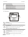
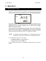
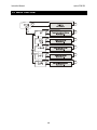
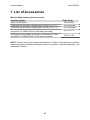
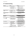
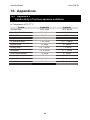
Instruction Manual
αlpha-CON550
Conductivity Monitor
mS/µS/ºC/ºF meter
Technology Made Easy ...
68X216870 Rev 3 Aug 07
Preface
This manual serves to explain the use of the αlpha-CON 550 Industrial
Conductivity Monitor. The manual functions in two ways, firstly as a step by step
guide to help the user operate the instrument. Secondly, it serves as a handy
reference guide. This instruction manual is written to cover many anticipated
applications of the αlpha-CON 550 monitor. If you have doubts in the use of the
instrument, please do not hesitate to contact the nearest Eutech Instruments
Authorised Distributor.
The information presented in this manual is subject to change without notice as
improvements are made, and does not represent a commitment on part of Eutech
Instruments.
Eutech Instruments cannot accept any responsibility for damage or malfunction of the
unit due to improper use of the instrument.
Copyright ©2006 All rights reserved.
Eutech Instruments Pte Ltd.
Table of Contents
1. Introduction ...........................................................................................................1
1.1
1.2
1.3
1.4
Before You Begin ................................................................................................................... 1
Intended Use .......................................................................................................................... 1
Safety Instructions.................................................................................................................. 2
Taking Out of Service / Correct Disposal of the Unit ............................................................. 2
2. Getting Started ......................................................................................................3
2.1
2.2
2.3
2.4
2.5
Description of Instrument ....................................................................................................... 3
Measurement System ............................................................................................................ 4
Connecting Peripherals.......................................................................................................... 5
2.3.1 Connection Terminals.................................................................................................... 5
2.3.2 Switching Between Pt100 & Pt1000 Temperature Sensors.......................................... 6
2.3.3 Connecting Conductivity Probe ..................................................................................... 7
2.3.4 Connecting Temperature Probe .................................................................................... 7
Installation .............................................................................................................................. 8
2.4.1 Mechanical Dimensions................................................................................................. 8
2.4.2 Wall Mount..................................................................................................................... 8
2.4.3 Panel Mount................................................................................................................... 9
Display & Keypad ................................................................................................................. 10
2.5.1 Display Overview......................................................................................................... 10
2.5.2 Key Functions .............................................................................................................. 11
3. Operation .............................................................................................................12
3.1
3.2
Measurement mode ............................................................................................................. 12
Menu Overview .................................................................................................................... 13
4. Calibration Mode .................................................................................................14
4.1
4.2
About Calibration.................................................................................................................. 14
Calibration ............................................................................................................................ 15
5. Setup Mode ..........................................................................................................17
5.1
5.2
5.3
5.4
5.5
5.6
Enter Setup mode ................................................................................................................ 17
Temperature Coefficient Settings......................................................................................... 18
Temperature Settings........................................................................................................... 19
Measuring Range Settings................................................................................................... 21
Configuration Settings .......................................................................................................... 22
Viewing Electrode Properties ............................................................................................... 24
6. Technical Specifications.....................................................................................25
7. List of Accessories .............................................................................................27
8. Troubleshooting ..................................................................................................28
9. General Information ............................................................................................29
9.1
9.2
9.3
Warranty............................................................................................................................... 29
Return of Goods ................................................................................................................... 29
Guidelines for Returning Unit for Repair .............................................................................. 29
10. Appendices .......................................................................................................30
10.1 Appendix 2 Conductivity of various aqueous solutions....................................................... 30
10.2 Appendix 4 - Abbreviations Used in LCD............................................................................. 31
αlpha-CON 550
Instruction Manual
1. Introduction
1.1 Before You Begin
We thank you for purchasing the αlpha CON 550 monitor.
The construction of the CON 550 monitor employs leading edge technology
and complies with safety regulations currently in force. Notwithstanding this,
improper use could lead to hazards for the user or a third-party, and/or
adverse effects on the plant or other equipment. Therefore, the operating
instructions must be read and understood by the persons involved before
working with the monitor.
The instruction manual must always be stored close at hand, in a place
accessible to all people working with the conductivity monitor.
If you have questions, which are not or insufficiently answered in this
instruction manual, please contact your authorized supplier. They will be glad
to assist you.
1.2 Intended Use
αlpha CON 550 monitors are intended solely for conductivity and
temperature measurement, as described in this instruction manual.
Any other use, or use not mentioned here, that is incompatible with the
technical specifications is deemed inappropriate. The operator is solely
responsible for any damage arising from such use.
Other prerequisites for appropriate use include:
– Comply with the instructions, notes and requirements set out in this
instruction manual.
– Comply with all local safety regulations concerning safety at work.
– Comply with all information and warnings in the documentation dealing
with the products used together with the conductivity monitor (housings,
sensors, etc.).
– Comply with local environmental and operational conditions.
1
αlpha-CON 550
Instruction Manual
1.3 Safety Instructions
- The αlpha CON 550 monitor should be installed and operated only
by personnel familiar with the instrument and who are qualified for
such work.
- A defective CON monitor must neither be installed nor put into
service.
- The αlpha CON 550 must only be operated under the specified
operating conditions (see section 6).
- The αlpha CON 550 must not be repaired by the customer.
- No modifications to the αlpha CON 550 are allowed. The
manufacturer/supplier accepts no responsibility for damage
caused by unauthorized modifications. The risk is borne entirely
by the user.
1.4 Taking Out of Service / Correct Disposal of the Unit
Taking out of Service
• First disconnect the unit from the power supply and then undo all electrical
connections.
• Remove the unit from the wall / panel.
Correct Disposal of the Instrument
When the αlpha CON 550 monitor is permanently taken out of service, obey
the local environmental regulations for correct disposal or send the
instrument to your local distributor, they will take care of proper disposal.
2
αlpha-CON 550
Instruction Manual
2. Getting Started
2.1 Description of Instrument
The Eutech Instruments’ αlpha CON 550 monitor is used for measuring
conductivity and temperature values. The monitor can be used for
applications such as water treatment and controlling, galvanicdecontamination, chemical processing, food processing, clean or wastewater
control and neutralization processes.
The monitor has many user-friendly and safety features which include:
•
Push-button keypad for calibration and setup
•
Built-in non-volatile memory to ensure that calibration and other
information are not erased if power supply fails
•
Menu-driven program that simplifies setup
•
Automatic temperature compensation (ATC)
•
Manual temperature compensation setting without the ATC probe, with
independent setting for calibration and process temperature
•
Large dual display LCD for easy reading with clear multiple annunciators,
operational mode indicators and error indicators
3
αlpha-CON 550
Instruction Manual
2.2 Measurement System
A typical measurement system consists of:
•
A conductivity process monitor
•
A conductivity sensor with integrated or separate Pt100/Pt1000
temperature sensor
•
An appropriate measurement cable
•
An immersion, flow or process assembly
Alpha CON 550 Monitor
lpha pH560
ESC
CAL
ENT
pH Monitor
Housing and
Sensors
Measurement Cable
4
Power Adaptor
(+9 V DC)
αlpha-CON 550
Instruction Manual
2.3 Connecting Peripherals
2.3.1 Connection Terminals
Remove Back Cover:
Remove the screws from the four corners at the back of the conductivity
monitor. Remove the back cover. The connectors are exposed on the back
PCBA as shown in the Figure 1 below.
Connectors:
•
J8 – 9V DC power connector (1.2mm diameter)
•
J9 – Relay connections
•
J10 - Conductivity electrode & Temperature probe connections (wiring has
to be done in the detachable connector
J8
J10 Connections
1. CON Low Current
2. CON Low Voltage
3. CON High Voltage
4. CON High Current
5. Pt 100 Compensate
6. Pt 100 Sense
7. Pt 100 GND
8. (No connection)
9V DC Power
Screw
J10
Figure 1: Outer Side of Back PCBA
5
αlpha-CON 550
Instruction Manual
2.3.2 Switching Between Pt100 & Pt1000 Temperature Sensors
The conductivity monitor supports both Pt100 & Pt1000 (2-wire or 3-wire)
temperature sensors. The default factory setting is Pt100. If you need to use
Pt1000 temperature sensor, you have to change the jumper setting (J7) as
described below.
Remove Back Cover:
Remove screws from the four corners at the back of the conductivity monitor.
Remove the back cover.
Remove Back PCBA:
Remove the screw located center of the back PCBA (Figure 1). Detach the
back PCBA from the monitor. Turn over the back PCBA. Locate J7 jumper on
the inner side of the back PCBA as shown in Figure 2 below.
J7
Jumper Setting for
Pt100
(Factory Default)
Jumper Settings for
Pt1000
Figure 2: Inner Side of Back PCBA
Set Jumper J7:
Set the J7 jumper to required sensor (Pt100 or Pt1000) type.
6
αlpha-CON 550
Instruction Manual
2.3.3 Connecting Conductivity Probe
Any industrial conductivity probe (2-cell or 4-cell) can be connected to the
conductivity monitor.
2-Cell Conductivity Probe:
1. Short Pin 1 & 2 of J10 connector using a jumper wire.
2. Connect CON low input wire (white) to Pin 2 of J10 connector.
3. Connect CON high input wire (black) to Pin 3 of J10 connector.
4. Short Pin 3 & 4 of J10 connector using a jumper wire.
4-Cell Conductivity Probe:
1. Connect CON low input wire (black) to Pin 1 of J10 connector
2. Connect CON low input wire (white) to Pin 2 of J10 connector.
3. Connect CON high input wire (orange) to Pin 3 of J10 connector.
4. Connect CON high input wire (blue) to Pin 4 of J10 connector.
2.3.4 Connecting Temperature Probe
For Automatic Temperature Compensated (ATC) conductivity readings, an
in-built temperature sensor is usually integrated with industrial conductivity
probes. Alternatively, a separate 100Ω Pt RTD temperature probe (2-wire or
3-wire) can be connected to the monitor.
3-Wire Probe:
1. Connect PT100 compensate wire to Pin 5 of J10 connector.
2. Connect PT100 sense wire to Pin 6 of J10 connector.
3. Connect PT100 GND wire to Pin 7 of J10 connector.
2-Wire Probe:
1. Short Pin 5 & 6 of J10 connector using a jumper wire.
2. Connect PT100 sense wire to Pin 6 of J10 connector
3. Connect PT100 GND wire to Pin 7 of J10 connector.
7
αlpha-CON 550
Instruction Manual
2.4 Installation
2.4.1 Mechanical Dimensions
lpha CON550
ESC
CAL
ENT
Conductivity Monitor
2.4.2 Wall Mount
1
2
Pierce through holes at
both sides
Cover the catch slots at
both sides with overlays
8
αlpha-CON 550
Instruction Manual
2.4.3 Panel Mount
1 Prepare panel cut-out of
92.0 mm X 92.0 mm
2 Remove back cover of
conductivity monitor
and slide it through
panel cut-out
Gasket
Panel
Panel
4 Insert threaded rods through catch
until conductivity monitor is held
against panel
3 Attach catch to both sides
of conductivity monitor
9
αlpha-CON 550
Instruction Manual
2.5 Display & Keypad
2.5.1 Display Overview
The Liquid Crystal Display (LCD) of αlpha CON 550 conductivity monitor has
two alpha-numerical displays (Upper and a Lower).
•
Upper display: Measured conductivity value is displayed when the
monitor is in normal operation (measurement) mode.
•
Lower display: Measured temperature value is displayed when the
monitor is in normal operation (measurement) mode. In conductivity
calibration mode, measured conductivity values are displayed here.
The two displays indicate function names, options & settings in Setup mode.
Refer ‘Appendix 4 - Abbreviations Used in LCD’ for more details.
The LCD also consists of various mode indicators, status annunciators and
unit of measurement indicators.
Upper Display
SETUP MEAS CAL
-8.8.8.8
READY
HOLD
ERR
R.
%
mS
µS
K=
- .8.8.8
°C °F
ATC
Lower Display
Mode Indicators
MEAS
Measurement mode (Refer Section 3.1 )
SETUP
Setup mode (Refer Section 5)
CAL
Calibration mode (Refer Section 4)
Status Annunciators
READY
Appears when the reading is stable
HOLD
Appears in Setup mode and Calibration mode to indicate that the relay function
is frozen
ATC
Appears when Automatic Temperature Compensation (ATC) is enabled.
Not visible when Manual Temperature Compensation (MTC) is enabled.
Flashes if the temperature probe is faulty in its ATC mode. (Refer Section 5.3)
ERR
Appears when an error occurs
Electrode annunciator. Blinks during calibration error (Refer Section 4.2)
Buffer annunciator. Appears in calibration mode (Refer Section 4.2)
K
Cell Constant (Refer Section 4.2)
10
αlpha-CON 550
Instruction Manual
Units of Measurement Indicators
mS
Conductivity in Milli Siemens
µS
Conductivity in Micro Siemens
R.
Line Resistance in Ohms (Refer Section 5.5)
%
Temperature Coefficient (Refer Section 5.2)
ºC
Temperature in Celsius (Refer Section 5.3)
ºF
Temperature in Fahrenheit (Refer Section 5.3)
2.5.2 Key Functions
lpha CON550
ESC
CAL
ENT
Conductivity Monitor
Key
CAL
Description
Enter Calibration mode
Enter Setup mode
ENT
Access sub screens (parameters) within a group of settings in Setup
mode
Confirm (save) setup parameters and numerical values
Start/Confirm calibration in Calibration mode.
Select a group of settings in Setup mode.
Select parameters and increment/decrement numerical values in Setup
and Calibration modes.
(When pressed continuously, speed of value increment/decrement
increases)
Returns to Measurement mode when both keys are pressed
simultaneously.
11
αlpha-CON 550
Instruction Manual
3. Operation
3.1 Measurement mode
When the conductivity monitor is powered on, the display shows all the LCD
segments briefly, and then automatically enters into the measurement mode.
MEAS
µS
READY
25.0
°C
ATC
The mode indicator ‘MEAS’ at the top of the display indicates that the
conductivity monitor is in measurement mode. The upper alpha-numerical
display shows the measured conductivity value, while the lower display
shows the temperature value.
The monitor has five selectable measuring ranges. The unit of measurement
and resolution of the conductivity reading depend on the selected measuring
range. If the monitor reads a conductivity reading beyond the selected
measuring range, the display shows ‘Or’ (over range) error indicator.
NOTE:
To guarantee accurate readings, the measuring system (the
conductivity monitor and the sensor) must be calibrated regularly.
From measurement mode you can access:
•
Calibration mode (by pressing CAL key)
•
Setup mode (by pressing ENT key)
For more details, refer section 4 for Calibration mode and section 5 for Setup
mode.)
12
αlpha-CON 550
Instruction Manual
3.2 Menu Overview
MEAS
µS
READY
CAL
ENT
°C
ATC
ENT
SETUP
ENT
ENT
ENT
ENT
ENT
ENT
ENT
ENT
ENT
ENT
HOLD
SETUP
HOLD
SETUP
HOLD
SETUP
HOLD
SETUP
HOLD
13
αlpha-CON 550
Instruction Manual
4. Calibration Mode
4.1 About Calibration
Calibration should be carried out each time a new electrode is attached to the
monitor or when you suspect that the monitor/electrode is out of calibration.
The monitor allows you to perform temperature calibration and conductivity
calibration.
About Temperature Calibration
It is important to ensure that temperature calibration is carried out prior to
conductivity calibration since temperature readings affect the accuracy of
conductivity measurements. It is recommended that temperature calibration
should be carried out only if the temperature value displayed on the monitor
is different from that of a calibrated thermometer. A temperature offset
calibration of ± 10 °C/± 18 °F from the default reading is allowed. Once a
temperature calibration is performed, conductivity calibration should be
carried out to ensure the accuracy of conductivity measurements.
About Measuring Ranges & Conductivity Calibration
The monitor has five selectable conductivity measuring ranges. You can only
calibrate one-point in the measuring range that you have selected for your
process application. You have to recalibrate the monitor every time you
change the measuring range since the calibration data of the monitor will be
reset every time a new measuring range is selected.
About Conductivity Calibration
During conductivity calibration, the monitor allows a calibration window of
± 40% from the measured default reading of the calibration standard. The
minimum allowable calibration point is 10% of the full scale reading of the
measuring range selected.
For best results, select a standard conductivity solution close to the sample
value you are measuring.
14
αlpha-CON 550
Instruction Manual
4.2 Calibration
The monitor requires one-point calibration. Conductivity calibration is always
carried out in the specific measuring range selected for the monitor. Make
sure, the monitor is set to desired measuring range before you enter
calibration mode (Refer Section 5.4 for selecting measuring ranges).
Select a suitable standard conductivity solution so that its conductivity value
is within 10% to 100% of the full scale of the selected measuring range of the
monitor. (For better accuracy, select the calibration standard to be nearly
50% of the full scale of the measuring range selected.) Prepare calibration
standard solution in two beakers – one for rinsing and the other for calibration.
Prepare separate de-ionized water for electrode rinsing.
All new calibration values will automatically override existing calibration data.
If you wish to abort the calibration, press ▲ and ▼ keys simultaneously and
the monitor reverts to measurement mode and the monitor will revert to
previous calibration data.
2
1
MEAS
2
ENT
HOLD
CAL
CAL
CAL
HOLD
K=
°C
4
3
CAL
µS
READY
µS
READY
HOLD
READY
HOLD
ATC
OR
ENT
CAL
HOLD
3
2
HOLD
K=
MEAS
CAL
READY
HOLD
READY
µS
ENT
µS
°C
ATC
1
From measurement mode press CAL key to enter calibration mode.
2
The display briefly shows the cell type (“2 CELL” or “4 CELL”) to which
the monitor is configured (Refer section 5.5 for cell type settings)
Next, the last configured cell constant (k) is displayed in the upper
display. Use ▲ or ▼ keys to adjust the cell constant to mach the cell
constant of the conductivity probe. Adjustable range is 0.10 to 10.0.
Press ENT key to confirm the new cell constant value.
Rinse the electrode in de-ionized water and then rinse with the
calibration standard. Immerse the probe in calibration standard solution
intended for calibration and swirl gently to create a homogenous sample.
Make sure there are no any air-bubbles trapped in the sensor.
3
The upper display shows the currently measured conductivity value of
the solution based on last calibration (if any). The lower display shows
uncalibrated (default) reading of the solution. The buffer annunciator
appears in LCD. The ‘READY’ annunciator appears when the reading is
stable.
Once the reading stabilizes press the ▲ or ▼ key to adjust the upper
display value to that of the standard solution. Press the ENT key to
accept the value.
15
αlpha-CON 550
Instruction Manual
NOTES: •
The acceptable calibration window is ±40% of the
displayed (default) value. For example, if the display is
1000 µS, the values to which it can be adjusted is 600 to
1400 µS.
•
If the conductivity reading of the solution is not within 10%
to 100% of the full scale of the selected measuring range,
calibration error occurs; LCD displays “ERR” and flash
electrode annunciator.
•
If the conductivity reading of the solution is beyond the
selected measuring range, calibration error occurs; LCD
displays “Or” (over range), “ERR” and flashes electrode
annunciator.
•
If calibration error occurs, exit form calibration mode by
pressing ▲ and ▼ keys simultaneously.
Calibration is completed. The display shows the calibration factor (FCt).
This serves as an indication of the effectiveness of the sensor which will
degrade with time and usage. An effective sensor should have a
calibration factor of 0.60 to 1.40
4
Press ENT key to return to measurement mode.
NOTES:
•
If you use a 2-cell conductivity sensor, make sure that the pin 1 and 2
are shorted and pin 3 and 4 are shorted on the J10 connector. (Refer
section 2.3.3 for more details)
•
When calibrating with manual temperature compensation, the monitor
automatically changes from the preset process temperature to the
calibration temperature. After leaving the Calibration mode, the
monitor switches back to the process temperature (for setting the
calibration temperature and the process temperature, see section 5.3)
WARNING: If you change the measuring range of the monitor after calibration
is done, the monitor will reset back to its factory default calibration.
16
αlpha-CON 550
Instruction Manual
5. Setup Mode
5.1 Enter Setup mode
The setup mode allows you to customize the settings of the conductivity monitor to
suite your requirements. While in measurement mode, press the ENT key to access
setup mode. LCD shows ‘SETUP’ mode indicator and the first page of setup (rAng –
Range settings). Press ▲ or ▼ key to access other pages of the setup mode.
MEAS
µS
READY
°C
ATC
ENT
SETUP
ENT
ENT
ENT
ENT
ENT
ENT
ENT
ENT
ENT
ENT
HOLD
SETUP
HOLD
SETUP
HOLD
SETUP
HOLD
SETUP
HOLD
NOTES:
•
To exit setup mode at any time press ▲ and ▼ keys simultaneously
(escape). The monitor returns to the measurement mode
•
If you do not press any key for 2.5 minutes, the monitor automatically
exists from the setup mode.
17
αlpha-CON 550
Instruction Manual
5.2 Temperature Coefficient Settings
Setting the temperature coefficient to match your process/calibration liquids allows
monitor to achieve conductivity readings with higher accuracy.
1
SETUP
ENT
HOLD
SETUP
SETUP
ENT
%
HOLD
HOLD
SETUP
4
3
2
SETUP
ENT
%
ENT
HOLD
2
ENT
HOLD
1
From measurement mode press ENT key to enter setup mode as
described in section 5.1. The LCD shows the first screen of setup mode
(rAng). Press ▲ or ▼ key to select temperature coefficient settings
screen (tC).
Press ENT key to access temperature coefficient settings (tC).
2
Select type of temperature coefficient: The upper display shows the
last configured temperature coefficient type (Lin or PUr). Press ▲ or ▼
key to select the desired type based on type of your process liquid.
PUr :
Pure water temperature coefficient: Select this if your process
liquid is pure water or ultra pure water.
Lin :
Linear temperature coefficient: Select this for all other
process liquids
Press ENT key to confirm your selection.
If PUr was selected:
The monitor reverts back to tC screen
If Lin was selected:
3
Select temperature coefficient for process liquid: The lower
display shows ‘P.tC’. The upper display shows last configured
temperature coefficient for process liquid (if any). The default value
is 2.1%. Press ▲ or ▼ key to select the desired value. Allowable
range: 0 to 10%.
Press ENT key to confirm your value.
4
Select temperature coefficient for calibration liquid: The lower
display shows ‘C.tC’. The upper display shows last configured
temperature coefficient for calibration liquid (if any). The default
value is 2.1%. Press ▲ or ▼ key to select the desired value.
Allowable range: 0 to 10%. Press ENT key to confirm your value.
The monitor reverts to tC screen.
Press ▲ or ▼ key to access other setup screens or press ▲ and ▼ key
simultaneously (escape) to return to measurement mode.
18
αlpha-CON 550
Instruction Manual
5.3 Temperature Settings
Automatic Temperature Compensation (ATC):
The conductivity value of a sample is affected by temperature. Use ATC feature of
the monitor to compensate for conductivity changes when the temperature of the
sample or process liquid fluctuates. Connect a separate temperature probe
(Pt100/pt1000) to the monitor if an integrated conductivity/Temperature probe is not
available.
Manual Temperature Compensation (MTC):
Set the monitor to MTC (disable ATC) when the temperature of sample or process
liquid is constant and a temperature probe is not available. If you disable ATC, the
monitor allows you to set your process temperature (P.ºC) and calibration
temperature (C.ºC). This allows calibration at a different temperature other than the
process temperature. Example: Setting calibration temperature of 25°C lets you
calibrate using standard solutions at 25°C, even if your process temperature is
different from 25°C.
1
SETUP
HOLD
SETUP
SETUP
ENT
°C
SETUP
HOLD
HOLD
ENT
°C
SETUP
SETUP
HOLD
HOLD
SETUP
ENT
°F
HOLD
ENT
°C
°C
ATC
ATC
6
3
2
5
SETUP
ENT
HOLD
HOLD
1
4
3
2
ENT
7
SETUP
ENT
ENT
HOLD
°C
From measurement mode press ENT key to enter setup mode as
described in section 5.1. The LCD shows the first screen of setup mode
(rAng). Press ▲ or ▼ key to select Temperature settings screen (SET
ºCF).
Press ENT key to access temperature settings (SET ºCF).
2
Selecting unit of measurement for temperature: The upper display
shows ‘Unit’ and the lower display shows the last configured unit of
measurement for temperature.
Press ▲ or ▼ key to select the desired units for temperature (ºC or ºF).
Press ENT key to confirm your selection.
3
Enable/disable ATC: The lower display shows ‘AtC’ and the upper
display shows the last configured ATC selection (‘On’ or ‘OFF’).
Press ▲ or ▼ key to enable (ATC On) or disable (ATC OFF) automatic
temperature compensation. Press ENT key to confirm your selection.
19
αlpha-CON 550
Instruction Manual
If ATC enabled (ATC On):
4
Selecting temperature offset: The upper display shows the last
configured temperature offset value (if any), otherwise the default is
zero. The lower display shows currently measured temperature
reading (including last configured offset value). LCD shows ‘ATC’
annunciator in lower-right corner.
Place a thermometer, which is known to be accurate, in your
sample or process liquid. Make sure your temperature probe is
placed in the same liquid. Compare the stabilized temperature
reading displayed on the monitor with the thermometer. If there is a
difference between the two readings (offset), you can adjust the
reading of the monitor. Press ▲ or ▼ key to adjust the lower
display to the correct temperature value.
5
As the lower display value changes, the monitor adjust the upper
display reading automatically to suit the new offset value. Up to ± 10
ºC/ ± 18 ºF offset is allowed.
Press ENT key to confirm the value. The monitor reverts to SET
ºCF screen.
If ATC disabled (ATC OFF):
6
Setting process temperature: The lower display shows ‘P.ºC’ and
the upper display shows the last configured process temperature.
Press ▲ or ▼ key to adjust the upper display to desired process
temperature. Allowable range: –10.0 to 125.0°C / 14.0 to 257.0°F.
Press ENT key to confirm the process temperature.
7
Setting calibration temperature: The lower display shows ‘C.ºC’
and the upper display shows the last configured calibration
temperature. Press ▲ or ▼ key to adjust the upper display to
desired calibration temperature. Allowable range: –10.0 to 125.0°C /
14.0 to 257.0°F.
Press ENT key to confirm the calibration temperature. The monitor
reverts to SET ºCF screen.
Press ▲ or ▼ key to access other setup screens or press ▲ and ▼ key
simultaneously (escape) to return to measurement mode.
To exit from any intermediate steps, press ▲ and ▼ keys simultaneously
(escape). The monitor returns to the first screen of temperature settings SET
ºCF.
20
αlpha-CON 550
Instruction Manual
5.4 Measuring Range Settings
The conductivity monitor has 5 different measuring ranges. You need to select a
range which is the most suitable for conductivity reading of your applications/samples.
The factory default is 2000 µS (0 to 2000 µS/cm).
The measuring range you select here will affect the way the monitor behaves in the
measurement mode and calibration mode. In measurement mode, if the conductivity
reading of the monitor is above the selected measuring range, the LCD shows “Or”
(over range) error. In calibration mode, the monitor adjusts calibration tolerance
based on full scale of the selected measuring range. The calibration is carried out
only for the selected measuring range.
WARNING: If you change the measuring range of the monitor after calibration is
done, the monitor will reset back to its factory default calibration.
1
2
From measurement mode press
ENT key to enter setup mode as
described in section 5.1. The LCD
shows the first screen of setup mode
(rAng). Press ENT key to access
measurement range setting (rAng).
The upper display shows the
currently selected measuring range.
The factory default is 2000 µS. The
lower display shows the currently
configured cell constant (k). (Refer
section 4.2 for setting cell constant)
Press ▲ or ▼ key to select the
desired measuring range. Press
ENT key to confirm your selection.
The monitor reverts to rAng screen.
SETUP
1
ENT
2
SETUP
HOLD
µS
ENT
HOLD
2
SETUP
µS
ENT
HOLD
2
SETUP
µS
ENT
HOLD
2
SETUP
mS
ENT
HOLD
2
SETUP
Measuring range
0.00 to 20.00 µS/cm
0.0 to 200.0 µS/cm
0 to 2000 µS/cm
0.00 to 20.00 mS/cm
0.0 to 200.0 mS/cm
Resolution
0.01 µS/cm
0.1 µS/cm
1 µS/cm
0.01 mS/cm
0.1 mS/cm
mS
ENT
HOLD
Press ▲ or ▼ key to access other setup screens or press ▲ and ▼ key
simultaneously (escape) to return to measurement mode.
21
αlpha-CON 550
Instruction Manual
5.5 Configuration Settings
Configuration settings let you select between 2-cell & 4-cell and reset the monitor to
factory defaults.
1
SETUP
HOLD
SETUP
3
2
ENT
SETUP
ENT
HOLD
HOLD
This screen appears only
when 2-cell is selected
and measuring range is set to
0.0 to 200.0 mS/cm
2
SETUP
R.
ENT
HOLD
4
ENT
SETUP
ENT
HOLD
4
SETUP
ENT
HOLD
4
SETUP
ENT
HOLD
MEAS
READY
µS
°C
ATC
1
From measurement mode press ENT key to enter setup mode as
described in section 5.1. The LCD shows the first screen of setup mode
(rAng). Press ▲ or ▼ key to select configuration settings screen
(Cnfg).
Press ENT key to access configuration settings (Cnfg).
2
Select cell type of the sensor: The lower display shows ‘CEL’. The
upper display shows the last configured cell type (‘2’ or ‘4’).
Press ▲ or ▼ key to select the cell type of your conductivity probe.
Press ENT key to confirm your selection.
NOTE: If you use a 2-cell conductivity sensor, make sure that the pin 1
and 2 are shorted and pin 3 and 4 are shorted on the J10 connector.
(Refer section 2.3.3 for more details)
3
Setting line resistance: The lower display shows ‘L.Ad’ and the upper
display shows the last configured line resistance; otherwise the default is
0.00 R.
NOTE: Line resistance of sensor cable constitutes to an error in
measurement of high conductivity values. The monitor will compensate
this error if you specify line resistance value in this setting. The setting is
available only if the cell type is set to 2-cell (step 3 above) and the
22
αlpha-CON 550
Instruction Manual
measuring range is selected to ‘0.0 to 200.0 mS/cm’.
Press ▲ or ▼ key to set the line resistance of the sensor cable
connected to the monitor.
Press ENT key to confirm your selection.
4
Reset to factory defaults: The display shows ‘nO dEF’.
Press ▲ or ▼ key to select:
nO dEF :
Not default reset of the monitor. User configured values
remain active, when confirmed by pressing ENT key.
FCt dEF:
Reset all settings of the monitor to factory defaults, when
confirmed by pressing ENT key.
CAL dEF:
Reset all calibration settings of the monitor to factory
defaults, when confirmed by pressing ENT key.
NOTE: Refer section 6 for factory/calibration default settings
Press ENT key to confirm your selection.
- If ‘nO dEF’ was selected, the monitor reverts to Cnfg screen.
Press ▲ or ▼ key to access other setup screens or press ▲
and ▼ key simultaneously (escape) to return to measurement
mode.
- If ‘FCt dEF’ or ‘CAL dEF’ was selected, the monitor performs the
selected reset and returns to measurement mode.
Press ▲ or ▼ key to access other setup screens or press ▲ and ▼ key
simultaneously (escape) to return to measurement mode.
To exit from any intermediate steps, press ▲ and ▼ keys simultaneously
(escape). The monitor returns to the first screen configuration settings (Cnfg).
23
αlpha-CON 550
Instruction Manual
5.6 Viewing Electrode Properties
Each time you calibrate the conductivity sensor, the monitor re-calculates the
calibration factor of the sensor and shown in the LCD at the end of calibration. The
setup mode allows you to view the last saved calibration factor and cell constant at
any time.
2
1
SETUP
HOLD
1
ENT
SETUP
ENT
HOLD
SETUP
ENT
HOLD
From measurement mode press ENT key to enter setup mode as
described in section 5.1. The LCD shows the first screen of setup mode
(rAng). Press ▲ or ▼ key to select viewing electrode properties screen
(CdAt).
Press ENT key to view electrode properties (CdAt).
2
Cell constant: The lower display shows ’CEL’ and the upper display
shows the last configured cell constant.
Press ENT key.
3
Calibration factor: The lower display shows ‘FCt’ and the upper display
shows the calibration factor based on the last conductivity calibration.
NOTE: The upper display shows ‘- - - ‘ if the monitor has not been
calibrated yet or the monitor has been reset to factory defaults.
Press ENT key to quit from electrode properties screen. The monitor
reverts to CdAt screen.
Press ▲ or ▼ key to access other setup screens or press ▲ and ▼ key
simultaneously (escape) to return to measurement mode.
24
αlpha-CON 550
Instruction Manual
6. Technical Specifications
General Specification
Conductivity
Measuring Range:
0.00 - 20.00 µS/cm
0.0 - 200.0 µS/cm
0- 2000 µS/cm
0.00 - 20.00 mS/cm
0.0 - 200.0 mS/cm
Relative accuracy
System accuracy
Temperature
Measuring range
Resolution
Relative accuracy
Sensor
Compensation
Calibration
Conductivity
Number of calibration points
Calibration window
Calibration standard solution window
Temperature
Offset Adjustment
Display
LCD
Electrical Data and Connections
Conductivity Input
Connection terminal
EMC Specifications
Emission
Susceptibility
Resolution:
0.01 µS/cm
0.1 µS/cm
1 µS/cm
0.01 mS/cm
0.1 mS/cm
± 1% of full scale reading
The effective measuring range and the total system
accuracy depend on the sensor used with the monitor.
Please refer respective sensor documentation.
-10.0 to +125.0 oC
+14.0 to +257.0 oF
0.1 oC
0.1 oF
±0.5 oC
±1.0 oF
2 wire / 3 wire - Pt100 or Pt1000 (Jumper Selectable)
Automatic or Manual (reference at 25oC)
1 point
±40% of default reading
10% to 100% of the selected measuring range
± 10 ˚C/ ± 18 ˚F
7 segments display with symbols for status information
Screw Terminal (3.5mm pitch)
8-pin & 4-pin terminal blocks, DC power connector
(1.2mm diameter)
EN 61 36
EN 61326
Other
Power Input
Dimensions (W x H x D)
Weight (Estimated)
Ambient Temp. operating range
Maximum Relative Humidity
Universal +9 V DC Adaptor and 24V DC Supply
96mm x 96mm x 66 mm
210g
0 to 40 oC
80% up to 31 oC decreasing linearly to 50% at 40oC
25
αlpha-CON 550
Instruction Manual
Calibration Default Settings (CAL dEF)
Conductivity
Calibration factor
Reset to 1.000
Factory Default Settings (FCt dEF)
Conductivity
Calibration factor
Cell constant
Cell type
Measuring range
Line resistance
Temperature
Unit of measurement
Temperature compensation
Temperature coefficient
Temperature coefficient type
MTC (ATC Off)
Reset to 1.000
1.00
2-cell
0 to 2000 µS/cm
0.000 Ω
oC
ATC On
2.1% (Both process & calibration temp. coefficients)
Linear
25 oC (Both process & calibration temperature)
26
αlpha-CON 550
Instruction Manual
7. List of Accessories
Monitor Replacement and Accessories
Item Description
Alpha CON 550 Monitor
Conductivity cell, Epoxy body, Graphite sensor, w/3-wire Pt100, k = 0.1
Conductivity cell, Epoxy body, Graphite sensor, w/3-wire Pt100, k = 1.0
Conductivity 2 Cell type probe, 0.1 - 200μS; Cell constant, K=0.1 with
integrated Pt 100, Material SS316 and 25ft cable (open-ended)
Conductivity 2 Cell type probe, up to 200 mS; Cell constant, K=1.0 with
integrated Pt 100, Material SS316 and 25ft cable (open-ended)
Order Code
EC-PHCP0550
EC-CONSEN89X
EC-CONSEN88X
EC-CS10-0-1S
EC-CS10-1-0S
NOTE: Please contact your authorised distributor or dealer for the prices of extension
measuring cables and other accessories such as tee joints, electrode assembly, and
calibration solutions.
27
αlpha-CON 550
Instruction Manual
8. Troubleshooting
Problem
Power on, but no display
Cause
Unstable conductivity
reading
a) Air bubbles in the probe
b) Dirty probe
c) Probe not deep enough in
sample
a) Electrical noise interference
Oscillating temperature
readings
Slow response
Blinking ATC
Blinking electrode
annunciator
Or (Conductivity)
Or/Ur (Temperature)
a) Loose connections
b) Incorrect output voltage of
the power adaptor
c) Cables not in correct polarity
(+ and – position)
a) Dirty / Oily probe
a) No temperature probe
connection during ATC mode
a) Error in calibration
b) Conductivity value of the
calibration standard is not
within acceptable range
a) Conductivity reading is
above the selected
measuring range
a) Temperature probe is not
connected when ATC
enabled
b) Temperature value exceeds
above/ below the specified
range
28
Solution
a) Ensure cables make good
contact
b) Use an power adaptor with
specified output voltage
c) Re-wire loop cables with correct
polarity
a) Tap probe to remove air bubbles
b) Clean probe and recalibrate
c) Ensure that the sample entirely
covers the sensor of the probe
a) Ensure shield wire is properly
connected to pin 7
a) Clean probe
a) Ensure temperature sensing
cable makes good contact
a) Ensure calibration standard
solution is not contaminated.
Ensure electrode is clean
b) Ensure calibration standard is
within 10 to 100% of full-scale of
the selected measuring range
a) Ensure correct conductivity
measurement range is selected
a) Ensure electrode makes good
contact with monitor
b) Ensure temperature calibration is
done properly. Ensure process
temperature is within the
specified range
αlpha-CON 550
Instruction Manual
9. General Information
9.1 Warranty
Eutech Instruments warrants this product to be free from significant
deviations in material and workmanship for a period of one year from the date
of purchase. If repair is necessary and not the result of abuse or misuse
within the warranty period, please return by freight pre-paid and amendment
will be made without any charge. Eutech Instrument Customer Service Dept.
will determine if the product problem is due to deviations or customer abuse.
Out-of-warranty products will be repaired on an exchange basis at cost.
Exclusions
The warranty on your instrument shall not apply to defects resulting from:
•
•
•
Improper or inadequate maintenance by customer
Unauthorized modification or misuse
Operation outside of the environment specifications of the products
9.2 Return of Goods
Before returning goods for any reason whatsoever, the Customer Service
Dept. has to be informed in advance. Items must be carefully packed to
prevent damage during shipment, and insured against possible damage or
loss. Eutech Instruments will not be responsible for any damage resulting
from careless or insufficient packing.
Warning: Shipping damage as a result of inadequate packaging is the
user's/distributor’s responsibility. Please follow the guidelines below before
shipment.
9.3 Guidelines for Returning Unit for Repair
Use the original packaging material if possible when shipping the unit for
repair. Otherwise wrap it with bubble pack and use a corrugated box for
additional protection. Include a brief description of any faults suspected for
the convenience of Customer Service Dept., if possible.
29
αlpha-CON 550
Instruction Manual
10. Appendices
10.1 Appendix 2
Conductivity of various aqueous solutions
At Temperature 25 oC /77 oF
Solution
Ultra-pure Water
Conductivity
0.055 µS/cm
Resistivity
18.18 MΩ-cm
0.05 - 1 µS/cm
1 - 18 MΩ-cm
0.5 µS/cm
2 MΩ-cm
0.1 - 10 µS/cm
0.1 - 10 MΩ-cm
1 - 80 µS/cm
0.01 - 1 MΩ-cm
Mountain Water
10 µS/cm
0.1 MΩ-cm
Drinking Water
0.5 - 1 mS/cm
1 - 2 kΩ-cm
Waste-water
0.9 - 9 mS/cm
0.1 - 1 kΩ-cm
1.5 mS/cm
0.7 kΩ-cm
Brackish Water
1 - 80 mS/cm
0.01 - 1 kΩ-cm
Industrial Process Water
7 - 140 mS/cm
Rarely stated
53 mS/cm
Rarely stated
Power Plant Boiler Water
Distilled Water
De-ionized Water
De-mineralized Water
Potable Water Maximum
Ocean Water
30
αlpha-CON 550
Instruction Manual
10.2 Appendix 4 - Abbreviations Used in LCD
Abbreviation
Description
AtC
CAL
C.ºC
CdAt
CEL
CnFg
C.tC
dEF
FCt
HOLD
K
L.Ad
Lin
MEAS
Or
P.ºC
P.tC
PUr
rAng
Set
SETUP
tC
tyP
Ur
Automatic Temperature Compensation
Calibration mode
Calibration temperature
Electrode properties
Cell
Configuration
Temperature coefficient for calibration liquid
Default values
Factory (defaults)
Relay functions are hold
Cell constant
Linear resistance
Linear
Measurement mode
Reading is over range
Process temperature
Temperature coefficient for process liquid
Pure water
Range
Setting
Setup mode
Temperature Coefficient
Type
Reading is under range
31
NOTES
For more information on Eutech Instruments’ products, contact your nearest
distributor or visit our website listed below:
Eutech Instruments Pte Ltd.
Blk 55, Ayer Rajah Crescent,
#04-16/24 Singapore 139949
Tel: (65) 6778 6876
Fax: (65) 6773 0836
E-mail: [email protected]
Web-site: www.eutechinst.com
Distributed by: