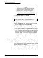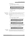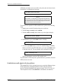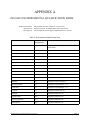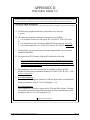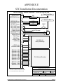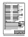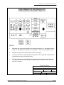
1
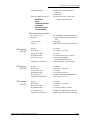
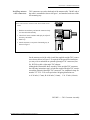
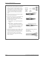
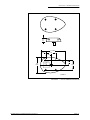
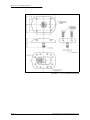
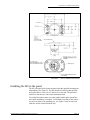
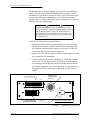
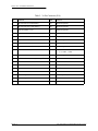
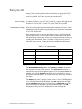
NORTHSTAR AVIONICS
M3 GPS APPROACH
P/N 1200-02-01
P/N 1200-03-01
CRSR
D
MSG
CRSR
M3 GPS APPROACH
USER
APT
APT
NORTHSTAR
ALRT
ACK
USER
PUSH ON
VOR
TRK
VOR
INFO
NDB
RTE
NDB
COMM
APCH
INT
INT
PRIMARY
SECONDARY
SETUP
TSO
Installation Manual
Revision D
March 25, 1998
Part No. GM611
© 1996, 1997, 1998 Northstar Avionics,
a division of CMC Electronics, Inc.
Northstar Technologies
30 Sudbury Road
Acton, Massachusetts 01720
Sales: 978/897-0770
Service: 978/897-7251
Fax: 978/897-7241
Revision history
Date
Pages
Revision
March 18, 1996
July 1, 1996
May 1, 1997
All
All
1,26,31
2, 5, 31
23
33,35,37
49
cover, 29
2
2,21
11
14
23
30
A (initial release)
B (update/rewrite)
C (add TSO approval)
(add P/N 1200-03-01)
(reducing interference)
(STC and FMS amendment)
(RSU-21 pin numbering)
D (area code change)
(power requirement of 1200-03)
(±120 mV To/From output)
(AN120 dimensions)
(Figure 7: P15 pin numbering)
(ELT interference)
(RMA # required for returns)
March 25, 1998
Ordering information
To receive additional copies of this publication, order the Northstar Avionics M3 GPS Approach Installation Manual (Part No. GM611).
Additional technical information is available on Northstar’s web site:
http://www.northstarcmc.com
Table of Contents
Technical information - - - - - - - - - - - - - - - - - - - - - - - - - - - 1
Scope of this manual - - - - - - - - - - - - - - - - - - - - - - - - - - 1
Equipment description - - - - - - - - - - - - - - - - - - - - - - - - - 1
Technical specifications - - - - - - - - - - - - - - - - - - - - - - - - - 2
Installation instructions - - - - - - - - - - - - - - - - - - - - - - - - - - 5
General information - - - - - - - Unpacking and inspection - - - - Preparing the antenna cables - - - Installing the GPS antenna - - - Installing the M3 in the panel - - Wiring the M3 - - - - - - - - - Initial checkout - - - - - - - - - Configuring the M3 - - - - - - - Limitations and approval procedures
-
-
-
-
-
-
-
-
-
-
-
-
-
-
-
-
-
-
-
5
5
6
9
13
19
22
23
26
Factory service policies - - - - - - - - - - - - - - - - - - - - - - - - - - 29
Limited warranty policy - - - Factory assistance by telephone
General service procedures - FliteCard updates - - - - - - Returning the unit for service -
-
-
-
-
-
-
-
-
-
-
-
-
-
-
-
-
-
-
-
-
-
29
29
30
30
30
DO-160C environmental qualification form
STC certificate 00464NY - - - - - - - Approved Flight Manual Supplement - - Specimen Form 337 - - - - - - - - - - STC installation documentation - - - - -
-
-
-
-
-
-
-
-
-
-
-
-
-
-
-
-
31
33
35
47
49
Appendices
Figures
Figure 1 — Final Assembly of Rear Panel Coax Connector
Figure 2 — TNC Connector Assembly - - - - - - - - - Figure 3 — Typical GPS Antenna Mounting Location - Figure 4 — AN120 Antenna Dimensions - - - - - - - Figure 5 — AN135 Antenna Dimensions - - - - - - - Figure 6 — AN155 Antenna Dimensions - - - - - - - Figure 7 — Mounting Tray (rear view) - - - - - - - - - Figure 8 — M3 Mounting Tray (exploded view) - - - - Figure 9 — M3 Wiring Diagram - - - - - - - - - - - - -
- - - - - - - - - - - 7
- - - - - - - - - - - 7
- - - - - - - - - - - 9
- - - - - - - - - - - 11
- - - - - - - - - - - 12
- - - - - - - - - - - 13
- - - - - - - - - - - 14
- - - - - - - - - - - 17
- - - - - - - - - - - 18
Tables
Table 1 — 24-Pin Connector (P15) - - - - - Table 2 — 36-Pin Connector (P16) - - - - - Table 3 — M3 Annunciators - - - - - - - - Table 4 — Potential VHF Interferences - - - Table 5 — Environmental Qualification Form -
- - - - - - - - - - - - - - - - - 15
- - - - - - - - - - - - - - - - - 16
- - - - - - - - - - - - - - - - - 19
- - - - - - - - - - - - - - - - - 23
- - - - - - - - - - - - - - - - - 31
SECTION ONE
Technical information
Scope of this manual
This manual describes the physical, mechanical, and electrical characteristics of the Northstar M3 GPS, included with the installation instructions.
Operational information is found in the Northstar M3 GPS Approach Reference Manual (Part No. GM601), which is supplied with the unit.
Equipment description
The Northstar M3 GPS consists of a panel-mounted GPS receiver-navigator, mounting tray, and GPS antenna. The unit is approved under
TSO-C129, Class A1. Use of the M3 is subject to airworthiness approvals
limited to en route, terminal area, and non-precision approach operation
under Visual Flight Rules (VFR) or Instrument Flight Rules (IFR). See
Appendix B, STC Certificate SA00464NY (as ammended), for Federal
Aviation Administration (FAA) Field Approval reference; and Appendix
C, FAA-Approved Airplane Flight Manual Supplement (AFMS, formerly
known as the Supplemental Air Flight Manual), for specific limitations
and operating procedures under the STC.
The unit receives radio signals from GPS satellites and calculates its latitude and longitude from these signals. The unit’s database is contained on
a user-changeable FliteCard™. It provides the coordinates of thousands of
airports, VOR and NDB transmitters, airway intersections, and routes and
approaches. A variety of navigation functions may be performed using this
data.
Interfacing the
Northstar M3 to
other equipment
The unit may be interfaced directly to many Course Deviation Indicators
(CDIs), Horizontal Situation Indicators (HSIs), Flight Directors, and/or
autopilots. Outputs also are provided to drive panel-mounted annunciators.
The unit also may be interfaced, through its built-in serial data port, to
devices like fuel-management systems, moving map displays, or other
devices designed to meet the Northstar serial data format described in the
Northstar Serial Data Format Specification V1.19 Firmware, Revision 2.2
(Part No. GM342). This document can be ordered by calling Northstar
Avionics.
M3 GPS INSTALLATION MANUAL Revision D
PAGE 1
Section One—Technical Information
The M3 may be interfaced to an altitude encoder, either by connecting the
individual encoder wires directly to the M3 or by using a Northstar 2006
Altitude Serializer. Altitude information enhances GPS accuracy and
availability. Interfacing an encoder is recommended for all installations
and is required for IFR-approved installations. Instructions for installing
the serializer are in the specifications in the Northstar 2006 Altitude Serializer Installation Manual (Part No. GM435), which is included with the
serializer.
NOTE:
All installations require use of Northstar fans (Part No. 1090
for 14 volts or Part No. 1091 for 28 volts) or equivalent fans
providing at least 2 CFM of cooling air. To ensure adequate
air flow to unit, up to three feet of ScatTubing is acceptable.
Technical specifications
Northstar M3 GPS
navigator ( Part No.
1200-02-01 or
1200-03-01)
Physical characteristics
Weight (with mounting tray) . . . . . . . 4.2 pounds
Dimensions:
Height—2.0 inches
Width—6.25 inches
Depth (from rear of bezel to rear of tray)—11.75 inches
Cooling. . . . . . . . . . . . . . . . . . . . . . . .Forced air cooling is required for all installations
Electrical requirements
Voltage . . . . . . . . . . . . . . . . . . . . . . . .10 to 35 VDC negative ground
Current . . . . . . . . . . . . . . . . . . . . . . . .1.5 A nominal at 14 VDC
0.85 A nominal at 28 VDC
Power . . . . . . . . . . . . . . . . . . . . . . . . . 35 watts nominal
(25 watts nominal for P/N 1200-02)
Interfaces to external equipment
CDI Loads . . . . . . . . . . . . . . . . . . . . .Up to five 1,000-Ohm loads
Full Scale . . . . . . . . . . . . . . . . . .±150 mV (maximum deviation output ±600
mV)
Valid Flag Loads . . . . . . . . . . . . . . . . Up to three 1,000-Ohm loads
260 µA for flag out-of-view
Superflag . . . . . . . . . . . . . . . . . . . . . . >18 VDC at 40 mA maximum
To/From Pointer . . . . . . . . . . . . . . . . . Up to three 200-Ohm loads, ±60 mV
nominal to pull pointer
(±120 mV option available—
contact factory)
PAGE 2
M3 GPS INSTALLATION MANUAL Revision D
Section One—Technical Information
Serial Data Channel . . . . . . . . . . . . . . EIA RS-485 (compatible with EIA
RS-422A)
EIA RS-422A
External Annunciator Drivers . . . . . . 200 mA max. current; 30 VDC max.
MESSAGE
voltage (switched ground)
RAIM
PARALLEL OFFSET
APPROACH
WAYPOINT ALERT
LOC ENERGIZE
Operational characteristics
DO-160C Env. Cat. . . . . . . . . . . . . . . F1CANBMXXXXXXZBABZUBXXX
Readouts. . . . . . . . . . . . . . . . . . . . . . . 32-character high-intensity alphanumeric
LED
Switch Legends . . . . . . . . . . . . . . . . . Backlighted
Memory . . . . . . . . . . . . . . . . . . . . . . . Continuously powered by 10-year battery
GPS antenna
(AN120)
Weight . . . . . . . . . . . . . . . . . . . . . . . . 0.3 pounds
Dimensions . . . . . . . . . . . . . . . . . . . . 4.30 inches × 2.70 inches
Height Above Skin. . . . . . . . . . . . . . . 0.70 inch
Depth Below Skin . . . . . . . . . . . . . . .0.575 inch max plus TNC connector
DO-160C Env. Cat. . . . . . . . . . . . . . . A2F2-AC[CLMY]XRFXSAX[AB][BZ]AVAL[1B]C
Manufacturer and Part No.. . . . . . . . . Comant Industries Antenna CI 405-7
GPS antenna
(AN135)
Weight . . . . . . . . . . . . . . . . . . . . . . . . 0.2 pounds
Dimensions . . . . . . . . . . . . . . . . . . . . 3.44 inches × 2.20 inches
Height Above Skin. . . . . . . . . . . . . . . 0.61 inches
Depth Below Skin . . . . . . . . . . . . . . .0.65 inch plus connector
DO-160C Env. Cat. . . . . . . . . . . . . . . F2AB(CLY)XSFDFSXXXXXXXXXC
Manufacturer and Part No.. . . . . . . . . Aero Antenna AT 575-9
GPS antenna
(AN155)
Weight . . . . . . . . . . . . . . . . . . . . . . . . 0.7 pounds
Dimensions . . . . . . . . . . . . . . . . . . . . 4.70 inches × 2.90 inches
Height Above Skin. . . . . . . . . . . . . . . 0.75 inch
Depth Below Skin . . . . . . . . . . . . . . .1.63 inches including connector
DO-160B Env. Cat. . . . . . . . . . . . . . . E1AB(JCYL)ASFDF-SZAAAAAAL2A
Manufacturer and Part No.. . . . . . . . . Canadian Marconi Company CMA-2052
M3 GPS INSTALLATION MANUAL Revision D
PAGE 3
Section One—Technical Information
(This page intentionally left blank)
PAGE 4
M3 GPS INSTALLATION MANUAL Revision D
SECTION TWO
Installation instructions
General information
This section contains information for installing and wiring the Northstar
M3 GPS, antenna, and interfaces.
All installation procedures should follow acceptable practices, methods,
and techniques as described in Advisory Circulars (AC) 43.13-1A and
43.13-2A.
Special installation
requirements
•
Before inserting or removing the M3 from the mounting tray, turn off
power to the tray using the avionics master switch or circuit breaker,
even if the unit’s power switch is turned off. This will prevent inrush
current from arcing across the power connector.
•
Use only a GPS antenna specified within this manual. Only the
Northstar AN120, AN135, and AN155 antennas are approved for use
with the M3. Consult the factory for special applications not covered
in these instructions.
•
The GPS antenna must be mounted on the top of the aircraft.
•
The GPS antenna should be located at least two feet away from any
other antennas and from the vertical stabilizer and canopy.
•
Forced air cooling must be supplied to the unit for all installations.
•
Electrical noise suppression of existing equipment may be required to
obtain satisfactory performance.
Unpacking and inspection
The shipping carton contains the following components and parts:
•
M3 GPS navigator (Part No. 1200-02-01 or 1200-03-01) and warranty card
•
Mounting tray assembly
•
GPS Antenna (AN120, AN135, or AN155)
•
M3 GPS Approach Reference Manual (GM601)
•
M3 GPS Approach Pilot’s Guide (GM606)
•
M3 GPS Approach Installation Manual (GM611)
•
Parts kit bag containing:
1 ea. air intake seal (HM502)
1 ea. coax connector socket (KC225)
1 ea. coax connector plug (KC310)
M3 GPS INSTALLATION MANUAL Revision D
PAGE 5
Section Two—Installation Instructions
4 ea. 3-48 × G-inch screws (HS106)
2 ea. 4-40 × G-inch screws (HS201)
2 ea. 4-40 × K-inch screws (HS213)
4 ea. #3 lockwashers (HW090)
4 ea. #4 lockwashers (HW100)
2 ea. #4 flat washers (HW115)
1 ea. 24-pin connector (KC230)
1 ea. 36-pin connector (KC270)
1 ea. cable cover (XC495)
2 ea. connector float washers (XC435)
4 ea. mylar shims (HM750)
Make sure all parts are present and have sustained no shipping damage. If
there is evidence of shipping damage, save the shipping carton and packing material to help substantiate your claim to the shipping company. Keep
a shipping carton on hand in case you have to return the unit to the factory
for service.
Preparing the antenna cables
Choosing the
antenna coax
To connect the antenna to the GPS sensor, use RG-58 C/U coaxial cable
(Alpha No. 9058C or equivalent). The outside diameter of the cable must
be approximately 0.24 inches to be compatible with the supplied connectors. For a typical RG-58 cable loss of 23 dB per 100 feet at 1500 MHz,
the cable length between the antenna and sensor should be at least 10 feet
and not more than 50 feet. If the antenna cable is routed near sources of
high electrical energy, then it is recommended that double-shielded coax
be used to reduce radio-frequency interference. Shields should be
grounded at both ends of the cable.
Type RG-59 coaxial cable is also acceptable. For typical RG-59 cable loss
of 18 dB per 100 feet, the cable length should be at least 15 feet and not
more than 80 feet.
PAGE 6
M3 GPS INSTALLATION MANUAL Revision D
Section Two—Installation Instructions
Installing antenna
cable connectors
TNC connectors are used at both ends of the antenna cable. The M3-end of
the cable is assembled as shown in Figure 1, and attached to the rear of the
M3 mounting tray.
Insert cable end into connector body. Start threads of nut
by hand.
1. Hold the nut stationary, and turn the connector body
over nut and cable assembly.
2. Check fit of center conductor and split pin; adjust if
necessary, and solder.
3. Install cap.
4. Attach connector to rear panel of mounting tray as
shown in Figure 7.
FIGURE 1 — Final Assembly of Rear Panel Coax Connector
On the antenna-end of the cable, install the supplied straight TNC connector as shown below in Figure 2. If required for the particular installation,
you may wish to substitute an optional right-angle TNC connector (Part
No. KC290) or add a right-angle TNC adaptor.
Although the illustrations show assembly of the straight TNC connector,
the following instructions apply to both the supplied straight TNC connector and the optional right-angle TNC connector. Use Amphenol crimp die
number 227-1221-13 or exact equivalent. Stripping dimensions are
A=0.34 inch (8.7 mm); B=0.09 inch (2.4 mm); C=0.15 inch (4.0 mm).
FIGURE 2 — TNC Connector Assembly
M3 GPS INSTALLATION MANUAL Revision D
PAGE 7
Section Two—Installation Instructions
1. Strip cable jacket, braid, and dielectric to dimensions
shown. All cuts must be sharp and square. Do not
nick braid, dielectric, or center conductor. Tinning of
center conductor is not necessary if contact will be
crimped. For solder method, tin center conductor,
avoiding excessive heat. Slide outer ferrule onto
cable.
2. Flare end of cable braid to ease insertion onto inner
ferrule. Do not comb out braid.
3. Place contact on cable center so it butts against cable
dielectric. Center conductor should be visible
through inspection hole in contact. Crimp or solder
the contact in place as follows:
•Crimp method—use
Cavity B of specified
die set.
•Solder
method—soft-solder the contact to
cable center conductor. Do not get any solder on outside surfaces of contact. Avoid
excessive heat to prevent swelling of
dielectric.
4. Install cable assembly into body of assembly so that
inner ferrule portion slides under braid. Push cable
assembly forward until contact snaps into place in
insulator. Slide outer ferrule over braid and up
against connector body. Crimp outer ferrule using
Cavity A of die set.
PAGE 8
M3 GPS INSTALLATION MANUAL Revision D
Section Two—Installation Instructions
Installing the GPS antenna
NOTE:
If the Northstar AN155 GPS antenna is used, it is necessary to
change a jumper wire inside the M3 unit to provide 12 volts to
the antenna. Contact the Northstar factory for details.
Mount the GPS antenna on the top of the fuselage as shown below in
Figure 3. Refer to Chapter Three of Advisory Circular 43.13-2A for practices, methods, and techniques. You must use an antenna that has been
approved for use with the Northstar M3. The antenna must be securely
grounded to the aircraft skin (remove any paint from the chosen location
on the skin).
FIGURE 3 — Typical GPS Antenna Mounting Location
Adequate isolation must be provided between the GPS antenna and any
transmitting antennas installed on the aircraft. Shadowing of the antenna
by aircraft structure can adversely affect operation of the GPS equipment.
Typically, a GPS antenna is located forward of the wings on the top of the
fuselage to minimize effects of the wings, tail, etc. during aircraft maneuvering.
Ideally, the antenna should be located in the clear (at least two feet from
any other antennas and at least three feet from transponder, DME, VHF,
and UHF transmitting antennas) and where it isn’t shadowed by the vertical stabilizer or the wings
M3 GPS INSTALLATION MANUAL Revision D
PAGE 9
Section Two—Installation Instructions
.
NOTE:
The GPS signal is typically weaker than the background
noise. Electrical noise near the antenna can adversely affect
GPS performance. Antenna installation in close proximity to
traffic alert and collision avoidance system (TCAS), satellite
communication (SATCOM), and other transmitting antennas,
particularly “L” band, should be carefully evaluated for
potential mutual interference
For rotorcraft installations, the effects of the rotor blades on antenna performance must be considered. Depending on the structure and mechanical
mounting considerations, the antenna may be located on the tail, in the
vicinity of the anti-collision light. Visibility of the anti-collision light must
not be impaired, however.
Approved GPS
antennas
PAGE 10
Three GPS antennas are currently approved for use with the Northstar M3.
These are available as Northstar Part Numbers AN120 (Figure 4), AN135
(Figure 5), and AN155 (Figure 6).
M3 GPS INSTALLATION MANUAL Revision D
Section Two—Installation Instructions
.70
MAX.
4.30 MAX
.90
1.750
1.000
.812
I.D.
P L AT E
2.70
MAX
1.625
CI 405-7
FIGURE 4 — AN120 Antenna Dimensions
M3 GPS INSTALLATION MANUAL Revision D
PAGE 11
Section Two—Installation Instructions
FIGURE 5 — AN135 Antenna Dimensions
PAGE 12
M3 GPS INSTALLATION MANUAL Revision D
Section Two—Installation Instructions
FIGURE 6 — AN155 Antenna Dimensions
Installing the M3 in the panel
The M3 is designed to be panel-mounted using the supplied mounting tray
and hardware (see Figure 8). The M3 should be located so that the pilot
and copilot have a clear view of, and access to, the unit. The preferred
location is near the top of the center instrument stack.
To avoid nicks and scratches, leave the rubber band in place around the
bezel until installation is complete. To facilitate pre-wiring of the connectors, the rear plate of the mounting tray (see Figure 7) may be removed
with four screws located inside the tray.
M3 GPS INSTALLATION MANUAL Revision D
PAGE 13
Section Two—Installation Instructions
The mounting tray is designed slightly oversized so the unit will slide in
easily even if the tray is somewhat distorted during mounting. A set of
self-adhesive mylar shims is provided to fill any space between the top or
bottom of the unit and the mounting tray. One or more shims may be
applied to the cover plates as necessary. Do not deform the cover plates by
installing more shims than needed.
CAUTION
Before inserting the unit into the wired mounting tray, double-check all wiring. A small but significant number of units
sustain damage because of incorrectly wired connections.
Such damage is not covered under warranty. Improper voltage application may result in vaporized circuit-board conductors within the unit.
Install the M3 in the panel as described below:
1. Make room for the unit in the instrument panel by relocating other
equipment as necessary. Install the mounting tray in the panel. Wire
the connectors mounted on the rear plate (see Figure 9). When finished, attach the rear plate to the mounting tray.
2. Supply clean, dry, forced cooling air to the air intake coupler. Cooling
air is required for all installations.
3. Carefully slide the unit into the mounting tray. Unlike the Northstar
M1, the M3 will stop approximately H inch from its final position.
The retaining rod will draw the unit the remaining distance into the
tray when it’s tightened. Use a J-inch flat-blade screwdriver inserted
through the hole in the front panel to tighten the rod. Do not overtighten!
AIR INLET COUPLER
Caution: Forced Air
Must Be Used
P16 (36-PIN CONNECTOR)
1
18
36
19
1
12
13
24
P15 (24-PIN CONNECTOR)
GPS ANTENNA CABLE
CONNECTOR
COAXIAL CABLE TO GPS ANTENNA
FIGURE 7 — Mounting Tray (rear view)
PAGE 14
M3 GPS INSTALLATION MANUAL Revision D
Section Two—Installation Instructions
Table 1: 24-Pin Connector (P15)
Pin
Function
Pin
Function
1
Nav Flag +
13
10–35 VDC power input
2
CDI + Right deviation
14
10–35 VDC power input
3
CDI + Left deviation
15
N/C
4
Nav Flag –
16
Ground
5
Ground
17
Ground
6
RS-485 serial A out
18
N/C
7
N/C
19
N/C
8
N/C
20
MESSAGE annunciator out
9
Ground
21
PARALLEL OFFSET annunciator out
10
+5 volts out
22
Ground
11
RS-485 serial B out
23
Power Ground
12
WAYPOINT ALERT annunciator out
24
Power Ground
M3 GPS INSTALLATION MANUAL Revision D
PAGE 15
Section Two—Installation Instructions
Table 2: 36-Pin Connector (P16)
Pin
Function
Pin
Function
1
RS-232 serial in (comm/trainer)
19
Altimeter input B1
2
RS-232 serial out (comm/trainer)
20
Altimeter input B2
3
To/From pointer (+ To)
21
Altimeter input B4
4
Superflag output (> +18 VDC = valid)
22
Reserved—do not use
5
Reserved—do not use
23
Reserved—do not use
6
Reserved—do not use
24
Altimeter input C4
7
RS-422 serial B out (future use)
25
Altimeter input C1
8
RS-422 serial A out (future use)
26
Altimeter input D4
9
RS-422 serial B in (altitude serializer)
27
Altitude encoder valid
(> +5 VDC = valid)
10
RS-422 serial A in (altitude serializer)
28
Altimeter input C2
11
APPROACH annunc. out (formerly VFR)
29
RAIM annunciator out
12
Reserved—do not use
30
APPROACH annunciator out
13
Reserved—do not use
31
LOC ENERGIZE out
14
Reserved—do not use
32
SPARE annunciator out
15
Reserved—do not use
33
Reserved—do not use
16
Altimeter input A1
34
To/From pointer (+ From)
17
Altimeter input A2
35
Ground
18
Altimeter input A4
36
Ground
PAGE 16
M3 GPS INSTALLATION MANUAL Revision D
M3 GPS INSTALLATION MANUAL Revision D
24-PIN PANEL RECEPTACLE
KC230
No. 3 INT. TOOTH
LOCKWASHERS
HW090
3-48 X 1/4 PAN HEAD
PHILLIPS SCREWS
HS106
36-PIN PANEL RECEPTACLE
KC270
CABLE COVER
XC495
AIR INTAKE BUSHING
XB265
(Part of XC491)
AIR INTAKE RETAINER RING
HW700
(Part of XC491)
FORCED AIR
WARNING LABEL
GD355
(Part of XC491)
POWER AND I/O CABLES
(Installer-supplied)
2 places
MOUNTING TRAY
XC375
P/N XC491 is REAR PLATE ASSEMBLY
REAR PLATE
XC940
(Part of XC491)
4-40 X 1/4 PAN HEAD
PHILLIPS SCREWS
4 PLACES
HS201
SLEEVE MOUNTING SCREWS
4 PLACES
(Installer-supplied)
AIR INTAKE SEAL
HM502
No. 4 INT. TOOTH
LOCKWASHERS
HW100
4-40 X 1/4 PAN HEAD
PHILLIPS SCREWS
HS201
RG58 C/U ALPHA No. 9058C
OR EQUIVALENT
HS201
4-40 X 3/8 PAN HEAD
PHILLIPS SCREWS
HS213
No. 4 INT. TOOTH
LOCK WASHERS
HW100
No. 4 FLAT WASHERS
HW115
COAX PANEL PLUG
KC225
FLOAT WASHERS
XC435
Section Two—Installation Instructions
FIGURE 8 — M3 Mounting Tray (exploded view)
PAGE 17
Section Two—Installation Instructions
+ To
Hi level
"SUPERFLAG"
(valid = 18 vdc)
+
To/Fr Pointer
+ Fr
NAV FLAG
RS-485
A
Northstar
B
serial
Shield data format
CDI
+ RIGHT
P15
+ LEFT
1 2 3 4 5 6 7 8 9 10 11 12
13 14 15 16 17 18 19 20 21 22 23 24
+10 to +35 Vdc
POWER
GND.
Supply
voltage
Instrument
Light Switch
PANEL
LIGHTS
MSG
Panel Dimmer
PARALLEL OFFSET
Relay
WAYPOINT ALERT
APPROACH
OPTIONAL
ANNUNCIATOR
DIMMER
CIRCUIT
(optional) RAIM
Northstar
C1
Comm
See Northstar C1 or
2006 Installation
Manual for details
RS-422 Serial interface
Northstar
2006
Altitude
Serializer
Use either serial or
parallel interface
to Altitude Encoder
A1
A2
A4
P16
1 2 3 4 5 6 7 8 9 10 11 12 13 14 15 16 17 18
19 20 21 22 23 24 25 26 27 28 29 30 31 32 33 34 35 36
Altitude
Encoder
ALTITUDE
VALID
D4
C1
C2
C4
B1
B2
B4
Note: if ALTITUDE VALID is not provided by Altitude Encoder,
connect P16-pin 27 to P15-pin 10
LOC ENERGIZE to autopilot (optional)
FIGURE 9 — M3 Wiring Diagram
PAGE 18
M3 GPS INSTALLATION MANUAL Revision D
Section Two—Installation Instructions
Wiring the M3
Many of the external connections described below are optional for VFR
installations, depending on the customer's desired configuration. If they
won’t be installed, leave the connector pins unconnected.
Power wiring
As shown in Figure 9, use P15, pins 13 and 14, to connect through a circuit
breaker to 12 or 24 VDC. Connect P15, pins 23 and 24 to ground.
Annunciator wiring
Wire the remote panel-mounted annunciators as shown in Figure 9. Each
annunciator output functions as a grounding switch, limited to a maximum
of 30 VDC and 200 mA.
Each annunciator driver circuit is designed to power a single bulb at the
rated current capacity. If two or more bulbs are connected to one output,
the initial inrush current may activate over-current protection circuitry preventing bulb illumination. Install a 10-Ohm 1-Watt resistor in series to
lower the inrush currect. Contact the factory for additional information.
Table 3: M3 Annunciators
Function
Conn./Pin
Abbreviation
Color
Message
P15 / 20
MSG
amber
Waypoint alert
P15 / 12
WPT or WP ALRT
amber
Parallel offset
P15 / 21
OFFSET or PTK
amber, white, or green
RAIM
P16 / 29
RAIM
amber
Approach
P16 / 11, 30
APCH or APR
blue or green
(Spare)
P16 / 32
The MESSAGE, WAYPOINT ALERT, and PARALLEL OFFSET annunciators
are required for en route IFR approval. The APPROACH annunciator is
required for non-precision approach approval. It is recommended that the
installer also wire the SPARE annunciator, bringing the leads to a convenient place behind the panel, and cap and stow them; these may be used in
the future.
The RAIM annunciator is optional. In the event of a loss of RAIM capability or a RAIM-detected satellite failure, the RAIM annunciator will light
and the MESSAGE annunciator will flash. Pressing MESSAGE on the M3
panel will display the appropriate RAIM-related message. The RAIM
annunciator simply serves as an indication of what message the
M3 GPS INSTALLATION MANUAL Revision D
PAGE 19
Section Two—Installation Instructions
MESSAGE button will show, and is not required, even for IFR installations.
The APPROACH annunciator signal is available on both pins 11 and 30 of
P16, although these pins are electrically independent. The earliest
en route-approved M3s required a VFR annunciator (connected to pin 11),
and described pin 30 as a “future APPROACH annunciator.” Later approvals removed this requirement for a VFR annunciator.
For new M3 installations, the APPROACH annunciator may be connected
to either pin 11 or pin 30.
For en route-approved installations that are being upgraded to non-precision approach status, determine which configuration of annunciators had
been previously installed from the following list:
•
If neither VFR nor APCH is present, install a new blue or green annunciator labelled APCH and connect it to either pin 11 or pin 30 of P16.
•
If VFR is not present, but APCH is present, no color change is required.
•
If VFR is present, but APCH is not present, change the legend from
VFR to APCH, and ensure that the color is either blue or green.
•
If both VFR and APCH annunciators are present, the VFR annunciator
must be disabled. Otherwise, both VFR and APCH would be illuminated when the M3 enters final approach mode.
The APPROACH annunciator is either blue or green.
CDI/HSI and
autopilot wiring
For an IFR installation, an indicator showing cross-track deviation must be
located in front of the pilot.
•
CDI/HSI — Wire as shown in Figure 9, using an appropriate switching device between the M3 and the instrument to enable selective
control by the pilot.
NOTE:
The M3 will not drive a CDI with a built-in converter, such as
the KI-208. Most others, however, having a 1,000-Ohm movement and requiring about 150 µA or 150 mV full scale, will
work.
•
PAGE 20
Nav Flag — Wire as shown in Figure 9. The M3 is designed to
directly drive a flag with a 1,000-Ohm input impedance. It should be
wired through the switching mechanism. A Nav Flag with a
300-Ohm movement may require a 2.7 K resistor installed in series
M3 GPS INSTALLATION MANUAL Revision D
Section Two—Installation Instructions
with the M3’s output to reduce the current drive. A “superflag” output also is provided.
Altitude encoder
wiring
•
To/From Pointer — Wire as shown in Figure 9, using the switching
device as described above. Note: A higher drive voltage (±120 mV) is
available. Contact the factory for information.
•
Localizer Energize Output — This output is provided for connection to autopilots requiring a signal to enable flying a coupled
approach. It is logically identical to the APCH annunciator output, but
is electrically isolated from it. Like the annunciator outputs, this signal functions as a grounding switch, active low, and is limited to a
maximum of 30 VDC and 200 mA.
Interface to an encoding altimeter is required for IFR installations and is
recommended for VFR use. The M3 has both a parallel and a serial interface available: either may be used. The serial interface requires the Northstar 2006 Altitude Serializer, which is already installed in many aircraft
being upgraded from an M2 to an M3.
To use the parallel interface, connect the 11 wires as shown in Figure 9. If
the altitude encoder does not provide an ALTITUDE VALID signal, see the
note on Figure 9.
To use the serial interface, follow the directions in the Northstar 2006 Altitude Serializer Installation Manual (Part No. GM435).
Be sure to designate which interface is used with the appropriate SETUP
command, described in “Designating the altimeter data interface” beginning
on page 25.
Serial interface
wiring
Two-conductor shielded twisted pair, such as Belden 9501 or
MIL-C-27500, is recommended for interconnecting equipment connected
to serial ports. The shield should be connected to chassis ground at both
ends of the cable.
The M3’s output data is binary coded, and includes latitude, longitude, signal status, SNR, ground speed, track angle, waypoint identification and
location, cross-track error, magnetic variation, distance and bearing to
waypoint, and flight plan information.
•
RS-485 Port for fuel management systems and/or moving map
display — This equipment must be configured to accept the Northstar
data format. Be sure to specify this format when purchasing these
units.
•
Northstar C1 Communications Transceiver — To interface to the
optional Northstar C1 Communications Transceiver, please refer to
M3 GPS INSTALLATION MANUAL Revision D
PAGE 21
Section Two—Installation Instructions
the Northstar C1 Installation Manual (Part No. GM620) for more
information.
The M3 doesn’t require any setup or initialization to work with the equipment connected to serial ports. Detailed serial data specifications are available in the Northstar Serial Data Format Specification, V1.19 Firmware,
Revision 2.2 (Part No. GM342).
Initial checkout
Installing the M3
Before inserting the M3 into the mounting tray, turn off the master avionics switch or circuit breaker. Double-check all wiring for proper connections, especially power and ground.
CAUTION
Make sure you do not apply primary voltage directly to the
left/right, to/from, and flag outputs of the unit; this action may
vaporize circuit-board conductors within the unit. Damage to
the unit from incorrectly wired connections is not covered
under warranty.
Carefully slide the unit into the mounting tray. Unlike the Northstar M1,
the M3 will stop approximately H inch from its final position. The
mounting rod will draw the unit the remaining distance into the tray when
it’s tightened. Use a J-inch flat-blade screwdriver inserted through the hole
in the front panel to tighten the rod. Do not overtighten!
Preliminary
inspection and test
Move the aircraft outside and away from large buildings. Turn the avionics
master switch on, and push the M3’s POWER switch in to turn it on. A
series of readouts shows the status of self-tests and the acquisition of GPS
signals. The very first time the M3 is powered-up after installation, the
unit will need to download a current almanac from the GPS satellites. This
process takes about 20 minutes. If power is interrupted during this time,
the process will repeat on the next power-up. After a successful almanac
load, subsequent power-ups should take less than a minute. The following
message is displayed when signal acquisition is complete:
NAVIGATOR READY / USE ANY SWITCH
Checking VHF
interference
PAGE 22
Harmonics of certain frequencies used for VHF transmissions can interfere with GPS signal reception. For installations that use GPS for primary
IFR navigation, testing must be performed to verify adequate isolation
M3 GPS INSTALLATION MANUAL Revision D
Section Two—Installation Instructions
from this interference. Tests shall be conducted by tuning each VHF transmitter to the frequencies listed below and transmitting for 30 seconds,
while observing the signal status of each or all satellites received. Degradation of individual satellite signals or all satellite signals to a point where
navigation using GPS is no longer possible may not be acceptable for use
under IFR, and requires that additional isolation or filter techniques are
included in the aircraft installation or appropriate limitation stipulated in
the Airplane Flight Manual Supplement (AFMS).
Table 4: Potential VHF Interferences
121.125 MHz
131.200 MHz
121.150 MHz
131.225 MHz
121.175 MHz
131.250 MHz
121.200 MHz
131.275 MHz
121.225 MHz
131.300 MHz
121.250 MHz
131.325 MHz
131.350 MHz
The worst-offending equipment is often the VHF comm transmitter and
associated antenna. Additional isolation may be obtained by increasing the
separation between the VHF and GPS antennas or, in some cases, by
re-routing antenna cables. Replacing the comm antenna with an inductive-fed type such as Comant CI-121 or Dorne Margolin DMC 70/11 may
help. Low-pass filtering inserted within the VHF transmitter/receiver
coaxial cable also may be used, provided that the VHF transmission and
reception isn’t significantly degraded.
It has been noted that some ELT transmitters re-radiate harmonics of
comm frequencies in the GPS band. Try disconnecting the ELT antenna if
this is suspected. If the ELT is interfering, try relocating the ELT antenna
or replacing the ELT with another type.
Configuring the M3
CDI centering and
scale adjustment
The interface to an external CDI (or HSI) and annunciators must be calibrated for each installation. Be sure to complete the entire procedure—only the fifth step causes the changes to be stored in the unit's
memory. This procedure also verifies correct wiring and operation of the
CDI interface and annunciators.
M3 GPS INSTALLATION MANUAL Revision D
PAGE 23
Section Two—Installation Instructions
NOTE:
If the unit has been designated as IFR-approved (by performing the procedure described in “Enabling IFR operation”
beginning on page 25), this setting can be checked but not
changed. If it’s necessary to change this setting after the unit
has been designated as IFR-approved, the unit first must be
set back to VFR-only, and then returned to the IFR-enabled
mode after the setting has been changed.
1. Turn the large secondary knob to SETUP.
2. Turn the small secondary knob to display:
CALIBRATE CDI,CK FLAGS,ANNCs.ACK?
3. Press ACK.
4. Rotate the small primary knob, if necessary, to precisely center the
deviation bar. When properly centered, press ACK.
5. The CDI should indicate five increments to the left. If necessary, to
achieve this, rotate the small primary knob, and then press ACK.
6. Check that the CDI indicates five increments right deflection. Rotate
the small primary knob to scan through the entire deviation range to
check its linearity and calibration accuracy. Compare the digital value
displayed by the M3 with the CDI’s reading. Turning this knob also
will test the Nav Flag, To/From Pointer, and External Annunciators.
Each knob click will activate one annunciator, as indicated on the
readout. Note that not all the annunciators that can be tested are necessarily installed in your aircraft.
Setting the time
zone
The M3 contains a battery-powered clock that enables it to constantly
maintain the time and date, even when it’s turned off. The battery has a
design lifetime of 5 to 10 years. Time (according to ZULU time) and date
are normally set at the factory during final inspection. The installer may
leave the time zone set to ZULU or may set the time zone to local time, if
desired. Designating the time zone will automatically adjust the displayed
time to the correct offset from ZULU time.
The M3 automatically sets its internal clock to the date and time obtained
from the GPS system as soon as the time is available, after power has been
turned on, and the satellites have been acquired. This process occurs every
time the M3 is powered up and re-acquires GPS satellites.
PAGE 24
M3 GPS INSTALLATION MANUAL Revision D
Section Two—Installation Instructions
To set the time zone:
1. Turn the large secondary knob to SETUP.
2. Turn the small secondary knob to display the time of day and time
zone:
EASTERN STD TIME IS 10:24:32
3. Turn the small primary knob to select either Coordinated Universal
Time (ZULU) or your local time zone as standard time (STD) or daylight savings time (DST).
4. Press ACK.
Designating the
altimeter data
interface
If the installation includes an interface to an altitude encoder, the installer
must designate whether the serial or the parallel interface was used.
To designate the altimeter data interface as serial or parallel, perform the
following steps:
1. Supply power to the M3 and push in the power switch to turn the unit
on.
2. Turn the large secondary knob to SETUP.
3. Turn the small secondary knob all the way to the right to display:
END OF FUNCTIONS
4. Simultaneously press both CRSR buttons to display:
SVC.CODE ------5. Press the right CRSR button, and use the small and large secondary
knobs to enter the code ALTSER for serial interface or ALTPAR for parallel interface. When done, press the right CRSR button to turn the
cursor off. The unit displays the confirmation message:
OK, THANK YOU
Enabling IFR
operation
If the installation has been approved for IFR use, the following procedure
must be performed for the M3 to operate in IFR-enabled mode. In
IFR-enabled mode, the altimeter data interface designation and the CDI
M3 GPS INSTALLATION MANUAL Revision D
PAGE 25
Section Two—Installation Instructions
calibration procedure aren’t accessible to the pilot, and each time the unit
is turned on, it will display the message:
APPROVED FOR IFR
NOTE:
The installer is responsible for ensuring that this function is
used appropriately. IFR-enabled mode is only allowed if all of
the requirements have been met and IFR approval has been
granted for the particular installation.
To set the M3 for operation in IFR-enabled mode, perform the following
steps:
1. Supply power to the M3 and turn the power switch on.
2. Turn the large secondary knob to SETUP.
3. Turn the small secondary knob all the way to the right to display:
END OF FUNCTIONS
4. Simultaneously press both CRSR buttons to display:
SVC.CODE------5. Press the right CRSR button, and use the small and large secondary
knobs to enter the code IFR. When done, press the right CRSR button
to turn the cursor off. The unit displays the confirmation message:
OK, THANK YOU
and will immediately switch to IFR-enabled mode.
To switch back to VFR-only mode, perform the above procedure, but enter
VFR as the service code.
Limitations and approval procedures
The Northstar M3 GPS is designed to meet or exceed the Minimum Operational Performance Standards (MOPS) of RTCA/DO-208 and has
received Technical Standard Order approval under TSO-C129, Class A1.
TSO compliance alone is not sufficient to substantiate airworthiness
PAGE 26
M3 GPS INSTALLATION MANUAL Revision D
Section Two—Installation Instructions
and acceptance of a Northstar M3 GPS installation. Installers seeking airworthiness and operational approval must consider the following:
•
Approvals shall be based upon compliance with Federal Aviation
Regulations (FAR) 21.33, 21.35, 23.1301, 23.1309, 23.1322,
23.1351, and 23.1431 appropriate for small airplanes or equivalent
rules specific to make, model, and type, as well as other relevant
FARs, Advisory Circulars, and FAA policy guidance.
•
Advisory Circular 20-138, Airworthiness Approval of Global Positioning System (GPS) Navigation Equipment for use as a VFR and
IFR Supplemental Navigation System, may be used as guidance for
obtaining “follow-on” field approvals for using GPS navigation under
VFR and IFR. Adherence to paragraphs 7.c.(2) for VFR or 8.c.(2) for
IFR and Appendix 1 of this AC should be followed to ensure that
every requirement is satisfied. Reference to the above paragraphs
must be made in the application for Field Approval on an FAA Form
337. See Appendix D for sample FAA Form 337 language.
•
For IFR-approved installations, an airplane flight manual supplement
will be required to reflect the specific characteristics of the aircraft
interface, if it’s considered to be complex (for example, multiple navigation source switching between HSI or CDI to flight director and/or
autopilot system). The flight manual supplement should contain any
pertinent limitations, emergency and abnormal procedures, normal
operating procedures, and performance changes. A copy of the
FAA-approved Airplane Flight Manual Supplement for STC
SA00464NY is in Appendix C.
•
Advisory Circular 20-138 outlines the provisions that permit an FAA
inspector to evaluate the installation, determine the adequacy of the
descriptive data that was prepared for the alteration, and approve the
flight manual supplement. Many FAA inspectors are qualified to perform this function, and will accept the responsibility; some FAA
inspectors are not qualified. To determine qualifications, check with
your local General Aviation or Flight Standards District Office.
•
For VFR installations, a flight manual supplement probably won’t be
required unless complex characteristics like multi-navigation system
switching are incorporated. A placard stating GPS NOT APPROVED
FOR IFR must be positioned within immediate view by the flight crew.
•
If approval has been obtained only for Class A2, a placard stating
GPS NOT APPROVED FOR APPROACHES must be installed.
M3 GPS INSTALLATION MANUAL Revision D
PAGE 27
Section Two—Installation Instructions
(This page intentionally left blank)
PAGE 28
M3 GPS INSTALLATION MANUAL Revision D
SECTION THREE
Factory service policies
Limited warranty policy
Northstar Avionics, a division of CMC Electronics, Inc., warrants the M3
free from defects in materials and workmanship for a period of two (2)
years from the date of shipment to an authorized dealer. This warranty
applies to the original purchaser and/or subsequent owner.
This warranty covers repair and/or replacement, at our option, of any parts
found to be defective, provided such defects, in our opinion, are due to
faulty material or workmanship, and are not caused by tampering, abuse,
or normal wear.
ALL WARRANTIES ARE F.O.B.
Northstar Avionics
30 Sudbury Road
Acton, Massachusetts 01720
Northstar will not accept or pay for any charges for warranty work
performed outside of our plant.
This warranty applies only to products in normal use. It doesn’t apply to
units or circuit boards defective due to improper installation, physical
damage, tampering, lightning or other electrical discharge, units with
altered serial numbers, or units repaired by unauthorized persons or in violation of Northstar service procedures.
Northstar Avionics assumes no responsibility for any consequential losses
of any nature with respect to any products or services sold, rendered, or
delivered.
The foregoing are the only warranties expressed or implied. No other warranties exist.
Factory assistance by telephone
Please feel free to call our technical staff for assistance with service or
installation at 978/897-7251 between 9:00 A.M. and 5:00 P.M. Eastern
Time, Monday through Friday. We do not accept collect calls. Please
have the serial number of the unit available when you call, along with as
many details of the problem as possible, including SNR readings, numbers
of PRNs in service, warning messages, and any other relevant information.
M3 GPS INSTALLATION MANUAL Revision D
PAGE 29
Section Three—Factory Service Policies
General service procedures
Repair of the Northstar M3 is performed at the factory. Factory service
includes a complete checkout and recalibration. Shipping charges are the
only costs for factory repair of a unit still under warranty.
FliteCard updates
FliteCard updates are made available on a 28-day update cycle. Install
updates by removing the unit from the instrument panel (use a J-inch
flat-blade screwdriver to loosen the retaining rod through the hole in the
front panel). In the Northstar M3, turning the retaining rod moves the unit
the last half-inch when inserting or removing the unit. Turn the rod to seat
or remove the unit—do not damage the threads by forcing the unit in or
out. Complete instructions are given in Section Three of the Northstar M3
GPS Approach Reference Manual. Press the button on the right side of the
M3 to eject the card. Fully insert the new card, and replace the unit in the
panel.
NOTE:
If you return a unit to the factory for repair, and you want the
latest update to be installed at the same time, you must
include payment to cover the cost of the update (unless the
unit is eligible for a free update). Purchase order numbers
from authorized Northstar dealers also are accepted. Call
Northstar for pricing.
Returning the unit for service
An RMA number is required for returning any units to the Northstar factory. Packages received without an RMA number will be returned. Contact
your Northstar dealer or the factory to obtain an RMA number.
Securely pack the unit in the original Northstar shipping carton, and return
it to the address shown on page 29. Include your name, complete shipping
address, daytime telephone number, complete description of the problem,
desired return date, and shipping method. If shipping method isn’t specified, units normally will be returned in about one week by UPS ground
transportation. If you require faster service, use air express and specify
your requirements. In emergencies, we can usually meet any reasonable
request.
New units won’t be supplied to replace those that have failed. Dealers
returning units for credit, instead of repair, will be assessed a 15% restocking charge.
PAGE 30
M3 GPS INSTALLATION MANUAL Revision D
APPENDIX A
DO-160C ENVIRONMENTAL QUALIFICATION FORM
Product nomenclature:
Manufacturer:
TSO Approval:
M3 Navigator (Part No. 1200-02-01 or 1200-03-01)
Northstar Avionics, 30 Sudbury Road, Acton, MA 01720
The Northstar M3 is FAA-approved under TSO-C129, Class A1
Table 5: Environmental Qualification Form
CONDITIONS
SECTION/
PARAGRAPH
Temperature and altitude
4.0
Equipment tested to category F1 (-55°C to +70°C to
55,000' MSL)
Low temperature operating
4.5.1
Equipment tested to Table 4-1
Low temperature survival
4.5.1
Equipment tested to Table 4-1
High short-time operating
4.5.2
Equipment tested to Table 4-1
High temperature survival
4.5.2
Equipment tested to Table 4-1
High temperature operating
4.5.3
Equipment tested to Table 4-1
In-flight loss of cooling
4.5.4
Equipment tested to Table 4-1
Altitude
4.6.1
Equipment tested to Table 4-1
Decompression
4.6.2
Not required for equipment
Overpressure
4.6.3
Not required for equipment
Temperature variation
5.0
Equipment tested to Category C
Humidity
6.0
Equipment tested to Category A
Operational shock
7.0
Equipment tested IAW Para. 7.2.1
Crash safety
7.0
Equipment tested IAW Para. 7.3.1
Vibration
8.0
Equipment tested to N, B, M
Explosion
9.0
Equipment identified as 'X'
Waterproofness
10.0
Equipment identified as 'X'
Fluids susceptibility
11.0
Equipment identified as 'X'
Sand and dust
12.0
Equipment identified as 'X'
M3 GPS INSTALLATION MANUAL Revision D
DESCRIPTION OF CONDUCTED TESTS
PAGE 31
Appendix A—DO-160C Environmental Qualification Form
Table 5: Environmental Qualification Form (Continued)
CONDITIONS
SECTION/
PARAGRAPH
DESCRIPTION OF CONDUCTED TESTS
Fungus
13.0
Equipment identified as 'X'
Salt spray
14.0
Equipment identified as 'X'
Magnetic effect
15.0
Equipment tested to Category Z
Power input
16.0
Equipment tested to Category B
Voltage spike conducted
17.0
Equipment tested to Category A
Audio frequency conducted
18.0
Equipment tested to Category B
Induced signal susceptibility
19.0
Equipment tested to Category Z
Radio frequency susceptibility
20.0
Equipment tested to Category U
Radio frequency emission
21.0
Equipment tested to Category B
Lightning-induced transient susceptibility
22
Equipment identified as 'X'
Lightning direct effects
23
Equipment identified as 'X'
Icing
23
Equipment identified as 'X'
Remarks:
1. Tests described in Sections 4, 5, 6, 7, and 8 were conducted by Associated Testing Laboratories,
Wayne, New Jersey. Test Reports No. T31438-001 and T21794-11 are on file at Northstar Avionics.
2. Tests described in Sections 15, 16, 17, 18, 19, 20, and 21 were conducted by Chomerics, Radiation Test Services. The reports are on file at Northstar Avionics.
PAGE 32
M3 GPS INSTALLATION MANUAL Revision D
Appendix B—STC Certificate SA00464NY
APPENDIX B
STC CERTIFICATE SA00464NY
M3 GPS INSTALLATION MANUAL Revision D
PAGE 33
M3 GPS INSTALLATION MANUAL Revision D
PAGE 34
Appendix C—Approved Fight Manual Supplement
APPENDIX C
APPROVED AIRPLANE FLIGHT MANUAL SUPPLEMENT (AFMS)
M3 GPS INSTALLATION MANUAL Revision D
PAGE 35
Appendix C—Approved Fight Manual Supplement
PAGE 36
M3 GPS INSTALLATION MANUAL Revision D
Appendix C—Approved Fight Manual Supplement
M3 GPS INSTALLATION MANUAL Revision D
PAGE 37
Appendix C—Approved Fight Manual Supplement
PAGE 38
M3 GPS INSTALLATION MANUAL Revision D
Appendix C—Approved Fight Manual Supplement
M3 GPS INSTALLATION MANUAL Revision D
PAGE 39
Appendix C—Approved Fight Manual Supplement
PAGE 40
M3 GPS INSTALLATION MANUAL Revision D
Appendix C—Approved Fight Manual Supplement
M3 GPS INSTALLATION MANUAL Revision D
PAGE 41
Appendix C—Approved Fight Manual Supplement
PAGE 42
M3 GPS INSTALLATION MANUAL Revision D
Appendix C—Approved Fight Manual Supplement
M3 GPS INSTALLATION MANUAL Revision D
PAGE 43
Appendix C—Approved Fight Manual Supplement
PAGE 44
M3 GPS INSTALLATION MANUAL Revision D
Appendix C—Approved Fight Manual Supplement
M3 GPS INSTALLATION MANUAL Revision D
PAGE 45
Appendix C—Approved Fight Manual Supplement
PAGE 46
M3 GPS INSTALLATION MANUAL Revision D
APPENDIX D
SPECIMEN FORM 337
NOTICE
Weight and balance or operating limitation changes shall be entered in the appropriate aircraft record. An alteration must be
compatible with all previous alterations to assure continued conformity with the applicable airworthiness requirements.
8. Description of Work Accomplished
(If more space is required, attach additional sheets. Identify with aircraft nationality and registration mark and date work completed.)
A. The following equipment and major components were removed:
1. (none)
B. The following equipment and major components were installed:
1. 1 ea. Northstar Avionics M3 Navigator, P/N 1200-02-01, TSO-C129 Class
A1
2. 1 ea. Northern Airborne Technology RS08-001 Remote Switch (if installed)
3. 1 ea. Comant Industries, Inc. Active GPS Antenna, P/N CI 405-7 (if installed)
C. All equipment was previously approved under Supplemental Type Certificate
Number SA00464NY.
D. Deviations from STC Number SA00464NY include the following:
(Note: List all equipment and major components removed, if any, and list all equipment and major
components installed which may require reference to manufacturer’s instructions. In addition, if a
“localizer override” function is NOT provided as part of a NAV/GPS switching system (if installed),
this must be listed as an STC deviation.)
E. The installation was made with reference to Northstar Avionics M3 GPS
APPROACH Navigator, Installation Manual, P/N GM611, Rev. B, July 1, 1996
(or later, as appropriate).
F. (For VFR Installations:)
The Northstar M3 Navigator is limited to VFR Navigation and was installed and
tested in accordance with AC 20-138, Paragraph 7.c.(2).
(For IFR Installations:)
The Northstar M3 Navigator is approved for VFR and IFR En Route, Terminal
Area, and Non-Precision Approach Navigation, and was installed and tested in
accordance with AC 20-138, Paragraph 8.c.(2).
X Additional Sheets Are Attached
M3 GPS INSTALLATION MANUAL Revision D
PAGE 47
Appendix D—Specimen Form 337
G. An Airplane (or Rotorcraft) Flight Manual Supplement, Document No. (or Report or
Part No.) (or Supplemental Flight Manual) is approved by the FAA Form 337, dated
_______, and has been installed within the Airplane (or Rotorcraft) Flight Manual. (Refer to AC 20-138, Appendix 2.)
H. All inspection records and other documents pertaining to this major alteration
are on file at (Your Avionics Company) under Work Order _______ .
I. The alteration was performed in accordance with AC 43.13-1A, Chapter 11,
Paragraphs 424, 425, 427, and 429 through 452, 464 through 466, 478 through
481, 514 through 519, and Chapter 15, Paragraphs 748 through 753, 820
through 822, 826, 827, and 842, and Chapter 16, Paragraphs 880 through 882
and 913; and AC 43.13-2A, Chapter 1, Paragraphs 1 through 12, Chapter 2,
Paragraphs 21 through 23, and Chapter 3, Figure 3.6 and Paragraph 39.
(Note: List appropriate subject Chapters and Paragraphs which apply to your alteration.)
J. The aircraft weight and balance, and the equipment list were amended in accordance with AC 43.13-1A, Chapter 13, Paragraphs 659 through 663.
K. An electrical load analysis was performed in accordance with AC 43.13-1A,
Chapter 11, Paragraph 428, and determined that the total load does not exceed
80% of the total rated alternator capacity.
END
PAGE 48
M3 GPS INSTALLATION MANUAL Revision D
APPENDIX E
STC Installation Documentation
INTERCONNECT WIRING DIAGRAM — NORTHSTAR M3 GPS
P16
RAIM Annunc. 29
APPROACH Ann. 11
Panel Light Bus
N/C
APR
P15
MESSAGE Ann.
WAYPOINT Ann.
OFFSET Annun.
10-35 VDC Input
10-35 VDC Input
Power Ground
Power Ground
RS-485 Serial A
RS-485 Serial B
Digital Ground
NAV Flag +
NAV Flag –
+ RIGHT Dev.
+ LEFT Dev.
20
12
21
13
14
23
24
6
11
5
1
4
2
3
Avionics Bus
MSG
WPT
PTK
“GPS”
T
5
DB9
2
5
A/C Ground
37
38
33
34
P/O RSU-21
Relay Assembly
P16
+TO Pointer
3
+FROM Pointer 34
Altimeter in A1
Altimeter in A2
Altimeter in A4
Altimeter in B1
Altimeter in B2
Altimeter in B4
Altimeter in C4
Altimeter in C1
Altimeter in D4
Altimeter Valid
Altimeter in C2
16
17
18
19
20
21
24
25
26
27
28
35
36
K
J
H
G
F
E
B
D
A
L
C
P/O Altitude Encoder
NORTHSTAR TECHNOLOGIES
30 SUDBURY ROAD, ACTON, MA 01720
Notes:
1. All wire to be AWG 22 unless otherwise noted.
2. All wire per MIL-W-22759-16/MIL-C-27500.
DRAWING TITLE: NORTHSTAR M3 GPS INSTALLATION
DRAWING NO.: 19960110
DRAWN BY: J.M.M.
DATE: 07/01/96
M3 GPS INSTALLATION MANUAL Revision D
SHEET: 1/4
APPROVED BY:
SCALE: N/A
REV: B
T.L. PEARSALL
FILE: INSPANEL.DWG
PAGE 49
Appendix E—STC Installation Documentation
INTERCONNECT WIRING DIAGRAM — RSU-21/NAV-GPS SOURCE/HSI SWITCHING
RSU-21 Relay
P901
21
22
23
24
25
26
+ Right
+ Left
+ To
+ From
+ Flag
- Flag
6
ILS Energize
33
34
37
38
+Right
+ Left
+ Flag
- Flag
35
36
8
9
10
11
12
13
5
K
H
9
B
1
Northstar
M3 GPS
P16
3
34
P1
b
V
Z
T
K
F
+ Right
+ Left
+ To
+ From
+ Flag
- Flag
T
1
P401
8
P15
2
3
1
4
+ To
+ From
17
4
1
14
Bendix/King
KX 165
Bendix/King
KI525A
Avionics Bus
NAV 1
GPS
NAV 1
27
GPS
39
49
5
DAY
NITE
SW
A/C Ground
50
Notes:
1. All wire to be AWG 22 unless otherwise noted.
2. All wire per MIL-W-22759-16/MIL-C-27500.
NORTHSTAR TECHNOLOGIES
30 SUDBURY ROAD, ACTON, MA 01720
DRAWING TITLE: NORTHSTAR M3 GPS INSTALLATION
DRAWING NO.: 19960110
DRAWN BY: J.M.M.
DATE: 07/01/96
PAGE 50
SHEET: 2/4
APPROVED BY:
SCALE: N/A
REV: B
T.L. PEARSALL
FILE: INSPANEL.DWG
M3 GPS INSTALLATION MANUAL Revision D
Appendix E—STC Installation Documentation
PANEL DRAWING FOR NORTHSTAR M3 GPS
SYSTEM AS INSTALLED WITHIN CESSNA 210
NOTES:
1.
Equipment and components installed in accordance with Section 2.4, “M3 Navigator Installation,” and FAA Advisory Circulars 43.13-1A, Chapter 11 and 43.13-2A, Chapters 1 and 2.
2.
Adequate cooling must be provided by the avionics cooling fan.
3.
The M3 circuit breaker is resettable trip-free type Klixon 7277-2-() labelled as specified and
located within the main circuit-breaker panel.
4.
Fabricate placards for circuit breakers and switches of white lettering on black background
in 12-point Helvetica font, and affix adjacent to appropriate annunciator, switch, or circuit
breaker as illustrated.
NORTHSTAR TECHNOLOGIES
30 SUDBURY ROAD, ACTON, MA 01720
DRAWING TITLE: NORTHSTAR M3 GPS INSTALLATION
DRAWING NO.: 19960110
DRAWN BY: J.M.M.
DATE: 07/01/96
M3 GPS INSTALLATION MANUAL Revision D
SHEET: 3/4
APPROVED BY:
SCALE: N/A
REV: B
T.L. PEARSALL
FILE: INSPANEL.DWG
PAGE 51
Appendix E—STC Installation Documentation
AN120 GPS ANTENNA INSTALLATION DRAWING FOR NORTHSTAR M3 GPS SYSTEM
F
O
R
W
A
R
D
C
L
CABIN TOP
(REF.)
Counterbore
Drill size "F"
Drill-four places
Number 41 drill bit
Northstar AN120
GPS antenna
(shown eight times
scale size for clarity)
NOTES:
NORTHSTAR TECHNOLOGIES
30 SUDBURY ROAD, ACTON, MA 01720
1. Cabin-top hole location for Northstar AN120 GPS antenna connector
1.55 inches aft of front spar carry-thru and on centerline.
2. Install AN120 with four AN570 #6-32 machine screws and four
AN442 #6-32 elastic stop washers.
3. Insert AN960 #6 flat washers between fuselage and AN442 nuts.
DRAWING TITLE: NORTHSTAR M3 GPS INSTALLATION
DRAWING NO.: 19960110
SHEET: 4/4
REV: B
4. Torque AN442 nuts to 12 –15 inch-pounds.
5. Follow recommended methods, techniques, and practices found
within FAA Advisory Circular 43.13-2A, Chapter 3.
PAGE 52
DRAWN BY: J.M.M.
DATE: 07/01/96
APPROVED BY:
SCALE: N/A
T.L. PEARSALL
FILE: AIRFRAME.DWG
M3 GPS INSTALLATION MANUAL Revision D