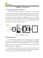
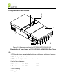
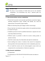
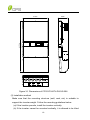
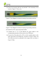
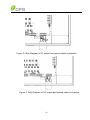
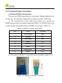
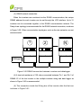
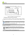
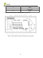
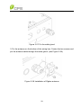
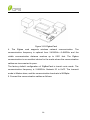
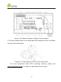
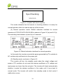
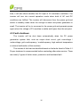
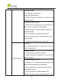
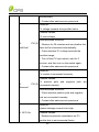
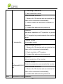
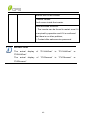
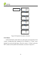
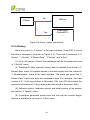
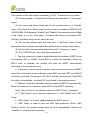
1
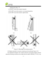
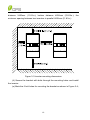
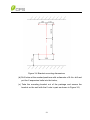
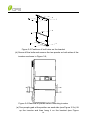
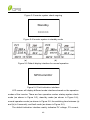
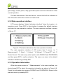
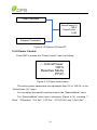
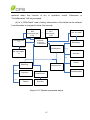
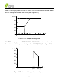
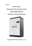
CPS SC Series Grid-tied PV Inverter CPS SC14KTL-DO/US-208 Installation and Operation Manual Ver 1.1 CHINT POWER SYSTEMS AMERICA CO., LTD. Address: 700 International Parkway Suite 102 Richardson TX 75081 Web: www.chintpower.com/na Email: [email protected] Service Hotline: 855-584-7168 SHANGHAI CHINT POWER SYSTEMS CO., LTD. All rights reserved. Specifications and designs included in this manual are subject to change without notice. CHINT POWER 2013/09-MKT PN: 9.0020.0117B0 Table of Contents Before You Start… ......................................................................................1 Chapter 1 IMPORTANT SAFETY INSTRUCTIONS ..................................2 Chapter 2 Overview ..................................................................................5 2.1 Inverter for grid-tied PV systems ...................................................5 2.2 Product features ............................................................................5 2.3 Circuit structure design ..................................................................6 2.4 Appearance description .................................................................7 Chapter 3 Installation ...............................................................................8 3.1 Recommendation before installation .............................................9 3.2 Mechanical installation ..................................................................9 3.3 Electrical installation ......................................................................17 3.3.1 DC connection ............................................................................17 3.3.2 AC and ground connection .........................................................19 3.3.3 Communication connection ........................................................22 Chapter 4 Operation .................................................................................32 4.1 Start-up ..........................................................................................32 4.2 Shut-down .....................................................................................32 4.3 Operation mode.............................................................................32 4.4 Grid connection and power generation..........................................34 4.5 Fault shutdown ..............................................................................35 Chapter 5 User Interface ..........................................................................43 5.1 Description of LCD panel ..............................................................43 5.2 Operation state ..............................................................................44 5.3 Interface and menu functions ........................................................45 5.3.1 Interface types ............................................................................45 5.3.2 Main operation interface .............................................................47 5.3.3 Operation information .................................................................47 5.3.4 Alarm ..........................................................................................48 5.3.5 History ........................................................................................49 5.3.6 System setup..............................................................................50 5.3.7 Power/PF ...................................................................................52 5.3.8 Power Control.............................................................................53 5.3.9 System protection parameters setup ..........................................54 Chapter 6 Technical Data .........................................................................58 Chapter 7 Limited Warranty.....................................................................61 Before You Start… This manual contains important information regarding installation and safe operation of this unit. Be sure to read this manual carefully before using. Thanks for choosing this CPS Grid-tied PV Inverter. This PV Inverter is a high performance and highly reliable product specifically designed for the North American Solar market. If you encounter any problems during installation or operation of this unit, first check this manual before contacting your local dealer or supplier. Instructions inside this manual will help you solve most installation and operation difficulties. Please keep this manual on hand for quick reference. 1 Chapter 1 IMPORTANT SAFETY INSTRUCTIONS (SAVE THESE INSTRUCTIONS) Please read this user manual carefully before product installation. CPS reserves the right to refuse warranty claims for equipment damage if the user fails to install the equipment according to the instructions in this manual. Warnings and symbols in this document DANGER: DANGER indicates a hazardous situation which, if not avoided, will result in death or serious injury. WARNING: WARNING indicates a hazardous situation which, if not avoided, could result in death or serious injury. CAUTION: CAUTION indicates a hazardous situation which, if not avoided, could result in minor or moderate injury. NOTICE: NOTICE indicates a hazardous situation which, if not avoided, could result in equipment working abnormally or property loss. INSTRUCTION: INSTRUCTION indicates important supplementary information or provides skills or tips that can be used to help you solve a problem or save you time. 2 Markings on the product HIGH VOLTAGE: The product works with high voltages. All work on the product must only be performed as described in this document. HOT SURFACE: The equipment is designed to meet international safety standards, but surfaces can become hot during operation. Do not touch the heat sink or peripheral surfaces during or shortly after operation. EARTH GROUND: This symbol marks the location of grounding terminal, which must be securely connected to the earth through the PE (protective earthing) cable to ensure operational safety. DANGER: Please disconnect the inverter from AC grid and PV modules before opening the equipment. When the PV array is exposed to light, it supplies DC voltage to this equipment. Make sure hazardous high voltage and energy inside the equipment has been discharged. Do not operate or maintain the inverter until at least 5 minutes after disconnecting all sources from DC and AC sides. WARNING: All the installation and cable connections should be performed only by qualified technical personnel. Disconnect the inverter from PV modules and the Power Grid before maintaining and operating the equipment. 3 NOTICE: This inverter is designed to connect AC power only to the public grid. Do not connect the AC output of this equipment directly to any private AC power equipment. CAUTION: CPS SC14KTL-DO inverter is approx 64kg (≈141 pounds). Please ensure the mounting is properly installed before hanging the the inverter on the bracket. 4 Chapter 2 Overview 2.1 Inverter for grid-tied PV systems CPS SC14KTL-DO/US-208 inverter is suitable for use with various commercial rooftop systems and distributed power station systems. Normally, the system mainly consists of PV modules, DC power distribution equipments, PV inverter and AC power distribution equipments (Figure 2-1). The inverter converts the DC from PV modules to AC with the same frequency and phase as the AC grid. All or part of the AC power is supplied to local loads, and the surplus power is supplied to the electricity grid. DC power AC power distribution distribution equipments equipments Bidirectional electric meter AC Grid Figure 2-1 Grid-tied PV system 2.2 Product features The two-MPPT design has the benefit of increasing the power generating efficiency of the whole PV system. The inverter has 2 MPPTs, so a separate array can be controlled by an independent Maximum Power Point Tracking (MPPT) control circuit. This means that the two arrays can be installed in different positions and orientations. The transformerless design of inverter with the benefit of small size, light weight, high power density, flexible installation and convenient maintenance provides the best cost performance for the whole PV system. 5 2.3 Circuit structure design The basic schematic diagram of CPS SC14KTL-DO/US-208 is shown in Figure 2-2. The input DC passes through surge protection circuitry, DC EMI filter, and the boost circuit to achieve maximum power tracking and boost up voltages. The inverter converts the DC energy to 3-phase AC energy. The high frequency components of AC voltage are removed with a line filter. Then the 3-phase AC energy is sent through two-stage relays and EMI filter to produce high quality AC power. DC_Switch INV AC_Switch Filter L1 PV1+ EMI Filter EMI Filter DC/DC PV1- L2 L3 Lightin g surge N Lightin g surge PV2+ EMI Filter DC/DC PE PV2Lightin g surge Figure 2-2 Schematic diagram of CPS SC14KTL-DO/US-208 6 2.4 Appearance description 3 2 1 8 7 6 5 4 Figure 2-3 Appearance sketch of CPS SC14KTL-DO/US-208 Description of main items of CPS SC14KTL-DO/US-208 (See Figure 2-3): 1. LCD key buttons: operate the functions and change settings of inverter 2. LCD display: indicates data 3. LED indicator lights: indicate the status of inverter 4. Holes for cable entry 5. DC switch: control the DC power on and off 6. AC switch: control the AC power on and off 7. Main housing 8. Wiring box 7 Chapter 3 Installation Below is the installation instruction of the inverter. Please read carefully and install the product step-by-step. Before installation, please check that the following items are included in the package: Table 3-1 Main items No. Q’ty Item Note CPS (1) SC14KTL-DO/US-208 1 Grid-tied PV inverter (2) (3) Mounting bracket 1 Installation and operation manual 1 (4) Warranty card 1 (5) Accessory kit 1 contains all necessary accessories The (5) Accessory kit contains items listed below: Table 3-2 Accessories Q’ty Purpose 8 pairs for bracket installation OT type terminal 1 For ground cable Pre-insulated end ferrule 20 RJ45 connecters 4 for communication cables Flange M5 nut 2 for ground cable Item M8x25 Expansion bolts&nuts 8 16 for DC input cables, 4 for AC output cables INSTRUCTION: The items in the accessory kit table above are for the standard configuration. The accessories may vary if optional parts are purchased. 3.1 Recommendation before installation Check that the product environmental specifications (protection degree, operating temperature range, humidity and altitude, etc) meet the requirements of the specific project location; Make sure that the power grid voltage is within normal range; Ensure that the local electricity supply authority has granted permission to connect to the grid; Installation personnel must be qualified electricians or people who have received professional training; Sufficient space is provided to allow the inverter cooling system to operate normally; Install the inverter away from flammable and explosive substances; Avoid installing the inverter in locations that exceed the temperature limits specified in the inverter data sheet to limit undesirable power loss; Do not install the inverter near the electromagnetic source which can compromise the normal operation of electronic equipment; 3.2 Mechanical installation (1) Dimensions The dimensions of CPS SC14KTL-DO/US-208 inverter are shown in Figure 3-1. 9 8.46in 215mm 41.73in 1060mm 21.42in 544mm Figure 3-1 Dimensions of CPS SC14KTL-DO/US-208 (2) Installation method Make sure that the mounting structure (wall, rack, etc) is suitable to support the inverter weight. Follow the mounting guidelines below: (a) If the location permits, install the inverter vertically. (b) If the inverter cannot be mounted vertically, it is allowed to be tilted 10 backward by Max. 15°. (c) Do NOT mount the inverter forwards. (d) Do NOT mount the inverter in a horizontal position. (e) Do NOT mount the inverter upside down. Figure 3-2 Mounting the inverter properly (3) Space required for inverter mounting on the wall (see Figure 3-3) The distances between the inverter and the surrounding objects should meet the following conditions: two sides from the walls ≥300mm (11.81in.); top 11 distance ≥300mm (11.81in.); bottom distance ≥600mm (23.62in.); the minimum spacing between two inverters in parallel ≥600mm (11.81in.). Figure 3-3 Inverter mounting dimensions (4) Secure the bracket with bolts through the mounting holes and install the inverter: (a) Mark the 6 bolt holes for mounting the bracket as shown in Figure 3-4; 12 Figure 3-4 Bracket mounting dimensions (b) Drill holes at the marked positions with a diameter of 0.4in. drill and put the 6 expansion bolts into the holes; (c) Take the mounting bracket out of the package and secure the bracket on the wall with the 6 nuts in pair as shown in Figure 3-5; 13 Figure 3-5 Positions of bolt holes on the bracket (d) Screw off the bolts and remove the two panels on both sides of the inverter as shown in Figure 3-6; Figure 3-6 Removal of panels before mounting inverter (e) Two people grab at the position on each side (see Figure 3-7a), lift up the inverter and then hang it on the bracket (see Figure 14 3-7b~c). Make sure the inverter is securely fixed on the bracket; Hand Grab Figure 3-7a Mounting inverter on the bracket Figure 3-7b Mounting inverter on the bracket 15 Figure 3-7c Mounting inverter on the bracket (f) Put the two removed panels back and secure them with 4 M4*12 bolts on each side, as shown in Figure 3-8. Figure 3-8 Securing panels on both sides 16 3.3 Electrical installation Inverter cable terminals of CPS SC14KTL-DO/US-208 are shown in Figure 3-9: A B C Figure 3-9 Inverter cable terminals Position Connection entry A Knockout holes for DC input cables B Knockout hole for AC output and ground cables C Knockout hole for communication cables 3.3.1 DC connection (1) To ensure the optimal performance of the inverter, please read the following guidelines before DC connection: (a) First, make sure that the maximum open circuit voltage of the PV modules is lower than 600Vdc under any conditions; (b) The No. 10-12AWG copper cored soft cables are recommended for DC input connection. (c) The inverter has 2 MPPTs with 4 DC input strings. Ensure that the Max. DC input current of each string does NOT exceed 10A. (2) Confirm that the PV modules for each MPPT of the inverter are of the same types and specifications before connection. 17 (a) Strip the skin 0.4 inch off the cables as shown in Figure 3-10: Figure 3-10 Wire stripping of DC input (b) Crimp the terminal as shown in Figure 3-11: Figure 3-11 Terminal crimping of DC input (c) The order of cable connection from left to right is PV1+, PV1-, PV2+, PV2-. Connect the PV1- and PV2- to the corresponding fuse socket of the negative pole and connect the PV1+ and PV2+ to the corresponding fuse socket of the positive pole as shown in Figure 3-12: Figure 3-12 Wire connection of DC input 18 3.3.2 AC and ground connection The following describes how to connect the AC output and grounding cables between the inverter and the public power grid: (1) Use the recommended cables: L1 (Line 1), L2 (Line 2), L3 (Line 3), Neutral and Gnd (Equipment grounding conductor):8AWG copper cored soft cables (2) Cable making for AC output: (a) Strip the skin 0.4 inch off the cables as shown in Figure 3-14: Figure 3-14 Diagram for wire stripping of AC output (c) Crimp the terminal as shown in Figure 3-15: Figure 3-15 Diagram for terminal crimping of AC output (3) Cable making for grounding: (a) The Gnd cable (Equipment grounding conductor) is recommended to be green or green with continuous yellow stripes, per National Electrical Code. Strip the skin 0.4 inch off the cables as shown in Figure 3-16: Figure 3-16 Diagram for wire stripping of grounding conductor 19 (b) Crimp the terminal with the ring terminal in the accessory kit as shown in Figure 3-17(a) or (b): Figure 3-17(a) Diagram for terminal crimping of grounding conductor Figure 3-17(b) Diagram for terminal crimping of grounding conductor (3) Connection of AC output and ground cables (a) Connect the L1, L2, L3 and Neutral AC output cables to the corresponding terminals of the socket on the PCB board. (b) Connect the Gnd cable with a M5 nut at the marked place on the lower right side of the Wiring box, as shown in Figure 3-18(a). The Gnd cable can also be connected to the copper stick as shown in Figure 3-18(b). 20 Figure 3-18(a) Diagram of AC output and ground cable connection Figure 3-18(b) Diagram of AC output and ground cable connection 21 3.3.3 Communication connection 1) Standard RS485 communication There are two RS485 signal ports on the inverter. Shielded cables should be used for communication cables with the maximum length of 3280 feet. (1) The communication of one single local inverter is to connect the RS485 communication bus cable through the RS485-1 or RS485-2 port of the inverter directly. Wiring requirement of RS485-1/2 is shown in Table 3-9: Table 3-3 RS485-1/2 wiring requirement No. Color Function 1 White orange 485+ 2 Orange N.C. 3 White green 485- 4 Blue N.C. 5 White blue N.C. 6 Green N.C. 7 White brown COM 8 Brown N.C. (2) The wires are labeled 1~8 from left to right, as shown in Figure 3-19: Figure 3-19 Diagram of RS485-1/2 wiring 22 (3) RS485 network connection: When the inverters are monitored via the RS485 communication, the unique RS485 address for each inverter can be set through the LCD interface. Up to 31 inverters can be connected together in the RS485 communication network. The Daisy-chain topology is recommended for the RS485 network connection, as shown in Figure 3-20. Other communication topologies, such as the star networks, are not recommended. 1 2 N Datalogger Figure 3-20 RS485 connection between inverters and datalogger (4) A terminal resistance of 120 ohms connected between Pin 1 and Pin 3 of RS485-1/2 of the last inverter in the multiple inverters string and data logger as shown in Figure 3-20 is recommended. (5) The connection inside the Wiring box of the inverter after the first one is shown in Figure 3-21: 23 Figure 3-21 Diagram of communication wiring 2) Optional communication card connection The inverter also supports 2 optional communication methods: Ethernet and ZigBee. Each communication card supports firmware upgrade by USB disk. INSTRUCTION: Please remove the communication cables in Figure 3-21 before installing the optional communication card. a.) Ethernet communication 1. Install the communication card and fasten the 4 screws. (see Figure 3-22) NOTICE: Please install the communication card in the wiring box as per the requirement of ESD to avoid damaging the card. 24 Figure 3-22 Install the Ethernet card 2. Crimp the communication cable, as shown below: Figure 3-23 Diagram of Ethernet wiring Table 3-4 Ethernet wiring requirement No. Color 1 White orange 2 Orange 3 White green 4 Blue 5 White blue 25 6 Green 7 White brown 8 Brown 3. Connect the communication cables as figure 3-24(a) or (b): Figure 3-24(a) Cable connection of Ethernet communication 26 Figure 3-24(b) Cable connection of Ethernet communication The Ethernet card is equipped with an Ethernet port for TCP/IP communication. The factory default IP address is 192.168.1.100. You may check the IP address by the finder.exe software. Use the Web Page function embedded in the Ethernet card to input the effective IP address in the IE address bar, such as //192.168.1.100. Then the user can set up the internet parameters and check the real-time information of inverter, etc. 27 Figure 3-25 Communication port on the Ethernet card b.) Zigbee communication 1. Install the Zigbee card in the wiring box, and fasten the screws, as follows: Figure 3-26 Install the Zigbee card NOTICE: Please install the communication card in the wiring box as per the requirement of ESD to avoid damaging the card. 2. Install and fasten the cable gland from the inside of the wiring box, as follows: 28 Figure 3-27 Fix the cable gland 3. Fix the antenna on the bottom of the wiring box. Fasten the two screws and put the antenna cable through the cable gland. (see Figure 3-28). Figure 3-28 Installation of Zigbee antenna 29 Figure 3-29 ZigbeeCard 4. The Zigbee card supports wireless network communication. The communication frequency is optional from 2.405GHz—2.480GHz and the visible communication distance reaches up to 6561 feet. The Zigbee communication is an excellent choice for the onsite where the communication cables are inconvenient to pave. The factory default configuration of ZigBeeCard is transit route mode. The communication frequency is 2.480GHz. Network ID is 0xFF. The transmit mode is Master-slave, and the communication baud rate is 9600pbs. 5. Connect the communication cables as follows: 30 Figure 3-30 Cable connection of Zigbee communication 6. Plug the unused holes on the cable gland with waterproof stick, and fasten the cap of the cable gland. Figure 3-31 Plug waterproof stick into the unused hole For more information about CPS monitoring solutions, please visit www.chintpower.com/na or contact our after-sales service center. 31 Chapter 4 Operation 4.1 Start-up Manual start-up: Manual start-up is required after initial installation or manual (fault) shut-down. Move the cursor from the main operation interface to “4 Setting”. Press ENT and input the password (PAGEUP -> RIGHT -> PAGEDOWN -> LEFT) to access the submenu “1 ON/OFF”. Then move the cursor to “ON” and press ENT to start the inverter. Then the inverter will start up and operate normally if the start-up condition is met. Otherwise, the inverter stands by. Automatic start-up: The inverter will start up automatically when the output voltage and power of PV modules meet the set point, AC power grid is normal, and the ambient temperature is within allowable operating range. 4.2 Shut-down Manual shutdown: Normally, manual shutdown is not required. It can be shut down manually if repair or maintenance is required. Move the cursor from the main operation interface to “4 Setting”. Press ENT and input the password (PAGEUP -> RIGHT -> PAGEDOWN -> LEFT) to access the submenu “1 ON/OFF”. Move the cursor to “OFF” and press ENT, and then the inverter will be shut down. Automatic shutdown: The inverter will shut down automatically when the output voltage and power of PV modules are lower than the set point, or AC power grid fails; or the ambient temperature exceeds the normal range. 4.3 Operation mode There are 4 operation modes. The following are corresponding indications for each mode. (1) System check mode for start up, as shown in Figure 4-1: 32 Sys.Checking >>>>>> Figure 4-1 System self check ongoing This mode indicates that the inverter is checking whether it is ready for normal operation after the manual start-up of the inverter. (2) Normal operation mode: Default indication interface for normal operation of CPS SC14KTL-DO/US-208 is shown in Figure 4-2 (a) and 4-2 (b). The switching time between (a) and (b) is 5 seconds. (a) (b) Figure 4-2 Default indication interface for normal operation In this mode, the inverter converts the power generated by PV modules to AC continuously and feeds into the power grid. (3) Standby mode, as shown in Figure 4-3: The inverter will turn into standby mode when the output voltage and power of PV modules do not meet the startup conditions or PV voltage and input power are lower than the set point. The inverter will check automatically whether it meets the startup conditions in this mode until it turns back to normal mode. The inverter will switch from standby mode to fault mode if malfunction occurs. 33 Standby >>>>>> Figure 4-3 Inverter system in standby mode (4) Fault mode, as shown in Figure 4-4: The inverter will disconnect from the power grid and turn into fault mode when the inverter or power grid fails. Check the specific cause through “Troubleshooting table” (Table 4-1) in terms of the fault message displayed on the LCD and eliminate the fault according to the instructions. SPICommErr Figure 4-4 Fault indication interface WARNING: All the installation and cable connections should be performed only by qualified technical personnel. Disconnect the inverter from PV modules and the Power Grid before maintaining and operating the equipment. 4.4 Grid connection and power generation The grid connection and power generation process of CPS SC14KTL-DO/US-208 is automatic. It will check constantly whether AC power grid meets the grid connection and power generation conditions. At the same 34 time, it will also check whether the DC input of PV modules is sufficient. The inverter will turn into normal operation mode when both of AC and DC conditions are fulfilled. The inverter will disconnect from the power grid and switch to standby mode when the sunlight is weak and power generation is small. The inverter will try to reconnect to the power grid and generate power again when the voltage of PV modules is stable and higher than the set point. 4.5 Fault shutdown The inverter will be shut down automatically when the PV power generation system fails, such as output short circuit, grid overvoltage / undervoltage, grid overfrequency / underfrequency, high ambient temperature or internal malfunction of the machine. The causes of fault can be identified based on the faults listed in Table 4-1. Proper treatment is recommended before contacting after-sales service. There are mainly 3 types of faults: alarm, protection and hardware fault. 35 Table 4-1 Troubleshooting Table Definition: Prompt detection of abnormal temperature Possible causes: 1. Temperature Sensor socket 1. TempSensorErr connecter has poor contact; 2. Temperature Sensor is damaged; Recommended solutions: 1. Observe temperature display; 2. Switch off 3-phase working power supply and then reboot the system; 3. Contact after-sales service personnel Alarm Definition: Communication inside inverter fails Possible causes: 1. Communication circuits inside inverter are loose; 2. SPICommErr 2. LCD software problem; 3. Inverter software problem; Recommended solutions: 1. Observe for 5 minutes and see whether the alarm will be eliminated automatically; 2. Turn off 3-phase working power supply and then reboot the system; 3. Contact our after-sales service center. 36 Definition: Fan (invisible from outside) inside inverter is working abnormally Possible causes: 1. Fan service life has expired; 3. IntFanErr 2. Fan socket connecter has poor contact. Recommended solutions: 1. Observe for 5 minutes and see whether the alarm will be eliminated automatically; 2. Switch off 3-phase work power supply and then reboot the system; 3. Contact after-sales service personnel Definition: The visible fan from outside view is working abnormally Possible causes: 1. Fan is blocked; 2. Fan service life has expired; 4. ExtFanErr 3. Fan socket connecter has poor contact. Recommended solutions: 1. Observe for 5 minutes and see whether the alarm will be eliminated automatically; 2. Check for foreign matters on fan blades; 3. Switch off 3-phase work power supply and then reboot the system; 4. Contact after-sales service personnel 5. EepromErr Definition: Internal alarm 37 Possible causes: Internal memory has a certain problem Recommended solutions: 1. Observe for 5 minutes and see whether the alarm will be eliminated automatically; 2. Contact after-sales service personnel Definition: Ambient temperature or temperature inside inverter is too high Possible causes: 1. Ambient temperature outside the inverter is too high; 2. Fan is blocked; 3. Cooling is affected because of incorrect installation. 1. TempOver Recommended solutions: 1. Confirm that external ambient temperature is Protect within the specified range of operating temperature; 2. Check whether radiation air inlet is blocked; 3. Whether radiation fan is blocked; 4. Check whether the location of installation is appropriate or not; 5. Observe for 30 minutes and see whether the alarm will be eliminated automatically; 6. Contact after-sales service personnel 2. GridV.OutLim Definition: Grid voltage exceeds the specified range, 38 Possible causes: 1. Grid voltage is abnormal; Power grid breaks down 2. Cable connection between the inverter and the grid is poor; Recommended solutions: 1. Observe for 10 minutes and see whether the alarm will be eliminated automatically; 2. Check whether the grid voltage is within the specified range; 3. Check whether the cable between the inverter and power grid is disconnected or has abnormalities; 4. Contact after-sales service personnel Definition: Grid voltage frequency is abnormal, or power grid is not detected Possible causes: 1. Grid frequency has abnormalities; 2. Cable connection between the inverter and 3. GridF.OutLim the grid is poor; Recommended solutions: 1. Observe for 10 minutes and see whether the alarm will be eliminated automatically; 2. Check whether the grid frequency is within the specified range; 3. Check whether the cable between the inverter and power grid is disconnected or has 39 abnormalities; 4. Contact after-sales service personnel Definition: PV voltage exceeds the specified value Possible causes: PV over-voltage Recommended solutions: 4. PV1(2) 1. Observe for 30 minutes and see whether the VoltOver* alarm will be eliminated automatically; 2. Check whether PV voltage exceeds the specified range; 3. Turn off the PV input switch, wait for 5 minutes, and then turn on the switch again; 4. Contact after-sales service personnel Definition: PV module is connected inversely Possible causes: 5. Reverse* PV1(2) PV positive pole and negative pole are connected inversely; Recommended solutions: 1. Check whether positive pole and negative pole are connected inversely; 2. Contact after-sales service personnel Definition: System leakage current is too high 6. GFCI.Err Possible causes: 1. Excessive parasitic capacitance on PV module due to environmental factor; 40 2. Grounding is abnormal; 3. Fault inside the inverter Recommended solutions: 1. Observe for 10 minutes and see whether the alarm will be eliminated automatically; 2.. Detect whether the electrical connection is abnormal 3. Contact after-sales service personnel Definition: Insulation impedance of PV positive to ground or PV negative to ground exceeds the specified range Possible causes: 7. IsolationErr Air humidity is high Recommended solutions: 1. Observe for 10 minutes and see whether the alarm will be eliminated automatically; 2. Check insulation of PV system; 3. Contact after-sales service personnel Definition: Internal protection of the inverter 8. IntProtect0010-01 80 Possible causes: Protection procedure occurs inside the inverter Recommended solutions: 1. Observe for 10 minutes and see whether the alarm will be eliminated automatically; 2. Contact after-sales service personnel Fault IntFault0010-0150 Definition: 41 Internal fault of the inverter Possible causes: Fault occurs inside the inverter Recommended solutions: 1. The inverter can be forced to restart once if it is required by operation and if it is confirmed that there is no other problem; 2. Contact after-sales service personnel INSTRUCTION: *The actual display of “PV.VoltOver” is “PV1VoltOver” or display of “PV.Reverse” is “PV1Reverse” or “PV2VoltOver”. *The actual “PV2Reverse”. 42 Chapter 5 User Interface 5.1 Description of LCD panel The CPS SC14KTL-DO/US-208 LCD panel mainly consists of LCD screen, LED indicator lights, buzzer and 6 keys, as shown in Figure 5-1. Interpretation for the indicator lights is shown in Table 5-1 and function of the keys is shown in Table 5-2. Table 5-1 LED Indication LED light Name Status Light Working POWER on Light off Light Grid-tied operation indication light on Flash Light off Light Grid GRID status indication light on Flash Light off FAULT Energized (control panel starts to work) power light RUN Indication Power supply not working In grid-tied power generation state Derated running status (light up 0.5s, light off 1.6s) In other operation status or power supply not working Grid is normal Grid fault (light up 0.5s, light off 1.6s) Power supply not working Fault Light status on indication Slow Indicates Alarm (light up 0.5s, light off light flash 2s) Indicates a Fault 43 Fast Protective action (light up 0.5s, light flash off 0.5s) Light off No fault or power supply not working Table 5-2 Definitions of the keys Key Description Definition of function Escape key Back/end/mute Enter key Confirm entering the menu/confirm set point Up Page up in selection menu Down Page down in selection menu Left -1 when setting parameters Right +1 when setting parameters 5.2 Operation state Table 5-1 indicates the definitions of LED, i.e. indicates the information of the inverter’s operation state. It indicates that the system is energized and under DSP control when “POWER” lights up. “RUN” will light up when the inverter detects that the grid connection conditions meet the requirements and power is fed into the grid. “RUN” will blink if the grid is in derated running state during the period of feeding power into the grid. “GRID” will light up when the grid is normal during the operation of the 44 inverter. Otherwise, “GRID” will blink until the grid restores to normal. “FAULT” will blink quickly as a fault (except grid abnormality) occurs. “FAULT” will not light off until the fault is eliminated. The light will blink slowly when an alarm occurs. “FAULT” keeps being lighted up when an internal fault occurs. The buzzer will give alarms if a fault (involving power grid abnormality) occurs. 5.3 Interface and menu functions Users can perform the corresponding operations with the 6 function keys according to the indications of the LCD display. 5.3.1 Interface types (1) The LCD interface starts with the company logo once the system is energized, as shown in Figure 5-2. Figure 5-2 LOGO interface (2) Indication of inverter operation mode: Sys.Checking >>>>>> 45 Figure 5-3 Inverter system check ongoing Standby >>>>>> Figure 5-4 Inverter system in standby mode (a) (b) Figure 5-5 Default display interface for normal operation SPICommErr Figure 5-6 Fault indication interface LCD screen will display different mode interfaces based on the operation modes of the inverter. There are four operation modes: startup system check mode (as shown in Figure 5-3), stand-by mode (as shown in Figure 5-4), normal operation mode (as shown in Figure 5-5, the switching time between (a) and (b) is 5 seconds), and fault mode (as shown in Figure 5-6). The default indication interface mainly indicates PV voltage, PV current, 46 grid voltage, instant power, daily generated power and time information under normal operation. The fault information of the most recent / current fault will be indicated on the LCD screen when the inverter is in fault mode. 5.3.2 Main operation interface LCD screen displays “default indication interface” when the inverter is in operation mode. Press ESC in this interface to escape the default interface and enter the main operation interface. The main operation interface is shown in Figure 5-7. →1 Measurements 2 Alarm 3 History 4 Setting 5 Power/PF 6 Power Control Figure 5-7 Contents indicated on the main operation interface The main operation interface of LCD screen has 6 menus, i.e. “1 Measurements”, “2 Alarm”, “3 History”, “4 Settings”, ”5 Power/PF” and “6 Power Control”. The users may select options with PAGEUP and PAGEDOWN, and then press ENT to confirm selection. The users can return to the default indication interface by pressing ESC. 5.3.3 Operation information When the cursor moves to “1 Measurements” in the main interface, you should press ENT to select the operation information as shown in Figure 5-8. Check the information by pressing PAGEUP and PAGEDOWN. Return to the previous menu by pressing ESC. 47 1 Measurements Yield MPac Pac RunT 23.5kWh 14.1kW 13.8kW 1.3 h Pdc 14.3KW Uab Ubc Uca Freq 208.0V 208.9V 208.5V 60.0Hz Ia Ib Ic 38.3A 38.2A 38.3A Tmod Tamb 78.2C 50 C Upv1 Ipv1 Upv2 Ipv2 381.0V 18.8A 358.0V 20.0A Figure 5-8 Operation information indication 5.3.4 Alarm As described before, when faults occur during the normal operation of the inverter, corresponding fault message will be indicated in “2 Alarm” menu besides the sound and light alarms. Move the cursor to “2 Alarm” and press ENT to check out the specific fault information, as shown in Figure 5-9. 48 No 2 Alarm Yes NoError EepromErr Protect0010 … Figure 5-9 Alarm / failure information 5.3.5 History Move the cursor to “3 History” in the main interface. Press ENT to check the history information, as shown in Figure 5-10. There are 4 submenus in “3 History” : “1 ErrHist”, “2 Recent Data”, “3 Version” and “4 Etot”. (1) UP to 100 pieces of latest fault messages can be recorded and found in “1 ErrHist” menu. (2) The latest 21 days’ operation history data is available to be found in “2 Recent Data” menu. All variable names in the data comply with the content in “1 Measurements” menu of the main interface. The users can select the “2 Recent Data” menu and input the retraceable days (For example, the input number is 21. If the current date is December 15th, the LCD will indicate the operation information of 21 days before that date which is November 24th). (3) Software version, hardware version and serial number of the product are listed in “3 Version” menu. (4) Cumulative generated power since the first day the inverter began working is available to be found in “4 Etot” menu. 49 No NoError 1.St2010.12.15 20:50 SPI Error 2.Ed2010.12.15 20:59 SPI Error … Yes Pls input date 3 History 1 ErrHist 2 Recent Data 3 Version →4 Etot ←2→ ß—12/15 RunT Yield MPac 7.0 h 123.5KWh 20.0KW IEE1547 SN 11481220003 DSPVer. 0.01 LCDVer. 0.01 TotalTag (KWh) 152123.5 Figure 5-10 History menu and submenu 5.3.6 System setup Move the cursor to “4 Setting” in the main menu, and press ENT to input the password (PAGEUP -> RIGHT -> PAGEDOWN -> LEFT). Then you can access the menu to set up the parameters. There are 7 submenus in “4 Setting” : “1 Power ON/OFF”, “2 Language”, “3 Sounds”, “4 Systime”, “5 Commun.”, “6 MPPT Scan” and “7 ARC Setup”. (1) The inverter can be started and shut down with “1 ON/OFF” menu. Move the cursor to “ON” and press ENT, “ON State” will then be indicated at the bottom of LCD screen ; move the cursor to “OFF” and press ENT, then “OFF State” will be indicated as well. The inverter will stand by instead of working normally if the startup conditions are not met even “ON” is selected. 50 The inverter will be shut down immediately if “OFF” is selected in any cases. (2) Two languages, i.e. English and Chinese are available in “2 Language” menu. (3) Key beep and Alarm beep can be set mute/unmute in “3 Sounds” menu. “Key beep” and “Alarm beep” can be chosen by pressing PAGEUP and PAGEDOWN. Shift between “Enable” and “Disable” by pressing Left and Right if the cursor is on the “Key beep”. Complete the setup by pressing ENT. Similarly, the Alarm beep can be set up as well. (4) Set up the system date and time with “4 SysTime” menu (These parameters are of critical importance and will be used in history information). (5) Set the 485 communication parameters with “5 Commun.” menu. (6) The “6 MPPTScan” menu has three submenus. 1. The first submenu is used to enable/disable the function of MPPT scan by pressing LEFT or RIGHT. Press ENT to confirm the selection. When the MPPT scan is enabled, the inverter will scan the MPPT automatically according to the scheduled cycle. 2. “Cycle(min)” is the second submenu used to set the cycle time of MPPT scan. Move the cursor to the submenu, press ENT, and use LEFT and RIGHT to set the cycle time. The range is (30, 540), and the unit is minute. Press ENT to confirm the selection, or press ESC to get back to the previous menu. 3. “Manual” is the third submenu used to enable the MPPT scan manually. Move the cursor to the submenu, press ENT to start MPPT scanning. Note: The function is only effective when the “MPPTScan” is enabled. (7) “7 ARC Setup” menu has two submenus, ie. “ARC Option” and “ARC Clear”. 1. “ARC Option” is used to enable/disable the ARC function. 2. “ARC Clear” is used to clear the ARC fault protection. When “ARC Protect” occurs, the system cannot clear the fault automatically. Please use “ClearErr” to clear the fault manually. 51 Note: The warning “ARCBoard Err” cannot be cleared by “ClearErr”, but this warning doesn’t affect the start-up of the inverter. → ON OFF ON 1 Power ON/OFF 2 Language 3 Sounds →4 SysTime 5 Commun 6 MPPTScan 7 Arc Setup 4 Setting → 1 中文 2 English KeyBeep Enabled AlarmBeep → Disabled ↓ 2009 / 12 / 15 21 :14 ARC Operation → Enable ARC Clear CleraErr 1 < Enable > 2 Cycle(min) → 60 3 Manual → Address 2 BaudRate 3 1 2400 2 4800 3 9600 4 19200 Figure 5-11 System setup menu and submenu 5.3.7 Power/PF Move the cursor to “5 Power/PF” in the main interface. Press ENT to access and check the parameters of “ActivePower” and “PowerFactor”, as shown in Figure 5-12. The user can set the parameters of the two options through LCD operations as well as remote control by monitoring software. 52 Local Command ActivePower(%) 100.0 PowerFactor 1.000 Dispatch Command Figure 5-12 Options of Power/PF 5.3.8 Power Control Press ENT to access the “Power Control” menu, as follows: → ActivePower 100% Reactive Mode PF(P) Figure 5-13 Power control menu The active power parameters are adjustable from 0% to 100.0% in the “ActivePower (%)” menu. You can select the specific reactive mode in the “ReactiveMode” menu. The “ReactiveMode” menu has 6 submenus (Figure 5-14), including “1 None”, “2 Dispatch”, “3 Q Set”, “4 PF Set”, “5 PF(P) Set” and “6 Q(U) Set”. 53 1 None 2 Dispatch 3 Q Set 4 PF Set Figure 5-14 Submenus of ReactiveMode 1. None: No mode/Disable reactive mode 2. Dispatch: Remote power dispatch mode Note: When the dispatch mode is selected, the reactive parameters of the inverter will change according to the remote change order, including ActivePower, PF and Q values. 1 None → 2 Dispatch 3 Q Set 4 PF Set ActivePower(%) 100.0 →ReactiveMode None Figure 5-15 Enable the dispatch function 3. Q Set: Set the Q mode Note: Change the reactive power by adjusting the Q value (reactive compensation) 4. PF Set: Set the PF mode Note: Change the reactive power by adjusting the PowerFactor 5.3.9 System protection parameters setup By pressing PAGEDOWN and ENT at the same time in the main interface 54 and entering the password (PAGEUP -> PAGEDOWN -> RIGHT -> LEFT), the system parameter setup menu is accessed. This menu includes 4 submenus: “1 Syspara”, “2 Restart”, “3 Recover” and “4 ClrErrRecd”, as shown in Figure 5-16. (1) Set up the system protection parameters in “1 Syspara” menu. The specification of protection parameters is shown in Table 5-3. Table 5-3 Protection Parameters Table Setup range (lower limit, No. LCD indication Description 1. V.MaxI (V) Class I Max. grid voltage {224.0, 228.8, 249.0} 2. VmaxTripTI (S) Class I Max. trip time {0.08, 1.00, 600.00} 3. V.MinI (V) Class I Min. grid voltage {104.0, 183, 187.0} 4. VminTripTI (S) 5. V.MaxII (V) 6. VmaxTripII (S) 7. V.MinII (V) 8. VminTripTII (S) 9. F.MaxI (Hz) 10. FmaxTripTI (S) 11. F.MinI (Hz) Class I Min. grid voltage default & upper limit) {0.08, 2.00, 600.00} trip time Class II Max. grid voltage Class II Max. grid voltage trip time Class II Min. grid voltage Class II Min. grid voltage trip time Class I Max. grid frequency Class I Max. grid frequency trip time Class I Min. grid frequency 55 {0, 249.6, 485.0} {0.08, 0.16, 600.00} {100.0, 104, 183.0} {0.08, 0.16, 600.00} {60.00, 60.5, 63.00} {0.08, 300, 600.00} {57.00, 59.3, 60.00} Class I Min. grid 12. FminTripTI (S) 13. V.MaxRecover 14. V.MinRecover 15. V.RecoverT (S) 16. F.MaxRecover 17. F.MinRecover 18. F.RecoverT 19. PVStartVol (V) PV startup voltage {150.0, 295, 310.0} 20. SoftStep (KW/S) Soft step {0.1, 0.1, 1} frequency trip time Max. grid voltage recover value Min. grid voltage recover value Grid voltage recover time Max. grid frequency recover value Min. grid frequency recover value Grid frequency recover time {0.08, 300, 600.00} {208.0, 225, 249.0} {104.0, 186, 208.0} {0.08, 300, 600.00} {50.00, 60.4, 62.00} {58.00, 59.4, 60.00} {0.08, 300, 600.00} (2) “2 Restart” menu. If an internal fault shutdown happens, a severe fault has occurred inside the inverter. The user may perform a force restart once in this menu if the user needs to restart the inverter. INSTRUCTION: The “Restart” function is effective only when the fault “IntFault0010-0150” in the troubleshooting table occurs. The inverter may restore to normal operation automatically if alarm or protection faults occur. This function will not respond when the inverter is in operation mode and a “FaultOperated” alarm interface will be indicated. (3) “3 Recover” menu, the manufacturer’s parameter default value can be 56 restored when the inverter is not in operation mode. Otherwise, a “FaultOperated” will be prompted. (4) In “4 ClrErrRecd” menu, history information of the faults can be cleared. A confirmation is required to clear the records. GridV.Max(V) GridF.Max(Hz) → 208 GridVmaxTripT(S) …... → 60.2 0.20 Pls Input Pwd **** Are You sure? FmaxTripTI(S) 0.20 →1 SysPara. 2 Restart 3 Recover 4 ClrErrRecd Wrong Pwd Restarting.. Initialization? Pwd Error Pls Input Again **** If yes Success ! If no Failure! Restoring.. FaultOperated If yes Success ! FaultOperated ClearErrors? If no Failure! Success ! Figure 5-14 System parameter setup 57 Chapter 6 Model Name Technical Data CPS SC14KTL-DO/US-208 DC Input Max. PV Power 19kW Nominal DC Input Power Max. DC Input Voltage 1 14.6kW 600Vdc Operating DC Input Voltage Range 180-580Vdc Start-up DC Input Voltage / Power 300V / 100W Nominal DC Input Voltage 400Vdc Number of MPP Trackers 2 MPPT Voltage Range Max. Input Current (Imp) Max. short circuit current limit per MPPT Number of DC Inputs and Fuses DC Disconnection Type 300-540Vdc 50A (25A per MPPT) 45A 8 fused conductors (4 per MPPT) Load rated DC switch AC Output 1 Rated AC Output Power 14kW Max. AC Output Power 14kW Rated Output Voltage 208Vac Output Voltage Range 183-228Vac Grid Connection Type 3Φ/ N / PE Max AC Output Current 39A Rated Output Frequency 60Hz Output Frequency Range 57-63Hz Exceeding the rated voltage shown in “Max. DC Input Voltage” may cause permanent damage to the equipment. 58 Power Factor >0.99 (±0.8 adjustable) Current THD <3% AC Disconnection Type Load rated AC switch System Topology Transformerless Max. Efficiency 96.7% CEC Efficiency 96.0% Stand-by / Night Consumption <20W / <2W Environment Protection Degree NEMA 4 Cooling Variable speed cooling fans -13°F to +140°F / - 25°C to +60°C Operating Temperature Range (derating from +122°F / +50°C) Operating Humidity Operating Altitude 0-95%, non-condensing 6562ft / 2000m (derating from 4921ft / 1500m) Audible Noise <55db Display and Communication Display LCD + LED Communication RS485 Mechanical Data Dimensions (WxHxD) 21.4x41.7x8.5in / 544x1060x215mm Weight 141lbs / 64kg Safety UL1741:2010, CSA-C22.2 Safety and EMC Standard NO.107.1-01, IEEE1547; FCC PART15 Grid Standard IEEE1547: 2003, IEEE1547.1: 2005 59 1 Note : The output power of CPS SC14KTL-DO/US-208 inverter de-rates when the DC voltage of is lower than 300V. (See Figure 6-1) Po/Pn 100% 80% 60% 40% 20% 60 120 180 240 300 540 600 PV Voltage (V) Figure 6-1 DC voltage de-rating curve 2 Note : The output power of CPS SC14KTL-DO/US-208 inverter de-rates when the environmental temperature is higher than 122℉(50℃). (See Figure 6-2) Po/Pn 100% 80% 60% 40% 20% 122℉ 140℉ (50℃) (60℃) Tamb Figure 6-2 Environmental temperature de-rating curve 60 Chapter 7 Limited Warranty The warranty policy of this product is specified in the contract; otherwise, the warranty period is 5 years. For service, Chint Power Systems America will provide local support. For Warranty terms, please refer to the CPS America standard warranty policy in place at time of purchase . 61