1
PVI 36TL
INSTALLATION AND OPERATION MANUAL
Revision A
©2015, Solectria - A Yaskawa Company
PVI 36TL Installation and Operation Manual
PVI Series Inverters
IMPORTANT REGISTRATION AND
WARRANTY INFORMATION
For warranty to become active, this inverter
must be registered. To activate warranty and
register inverter, please visit the link below.
www.solectria.com/registration
DOCR-070588-A
Page 1 of 107
PVI 36TL Installation and Operation Manual
PVI Series Inverters
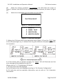
Before You Start…
This manual contains important information regarding installation and safe operation
of the PVI 36TL. Be sure to read this manual carefully before using the inverter.
Thank you for choosing a Solectria grid-tied PV Inverter. This PV Inverter is high
performance and highly reliable product specifically designed for the North American
Solar market.
If you encounter any problems during installation or operation of this unit, first check
the user manual before contacting your local dealer or supplier. This user manual is
applicable for the following model: PVI 36TL.
Instructions inside this user manual will help you solve most installation and
operation difficulties. Contact your local supplier if the problem still exists.
Please keep this user manual on hand for quick reference.
DOCR-070588-A
Page 2 of 107
PVI 36TL Installation and Operation Manual
PVI Series Inverters
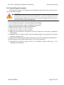
IMPORTANT SAFETY INSTRUCTIONS
SAVE THESE INSTRUCTIONS
Please read this user manual carefully before product installation. Solectria reserves
the right to refuse warranty claims for equipment damage if the user fails to install the
equipment according to the instructions in this manual.
Warnings and Symbols in this Document
DANGER:
DANGER indicates a hazardous situation which, if not avoided,
will result in death or serious injury.
WARNING:
WARNING indicates a hazardous situation which, if not avoided,
could result in death or serious injury.
CAUTION:
CAUTION indicates a hazardous situation which, if not avoided,
could result in minor or moderate injury.
NOTICE:
NOTICE indicates a hazardous situation which, if not avoided,
could result in equipment working abnormally or property loss.
INSTRUCTION:
INSTRUCTION indicates important supplementary information
or provides skills or tips that can be used to help you solve a
problem or save you time.
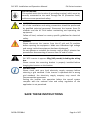
Markings on the Product
HIGH VOLTAGE:
This inverter works with high voltages. All work on the product must
only be performed as described in this document.
HOT SURFACE:
The equipment is designed to meet international safety standards,
but surfaces can become hot during operation. Do not touch the
heat sink or peripheral surfaces during or shortly after operation.
DOCR-070588-A
Page 3 of 107
PVI 36TL Installation and Operation Manual
PVI Series Inverters
EARTH GROUND:
This symbol marks the location of grounding terminal, which must be
securely connected to the earth through the PE (Protective Earth)
cable to ensure operational safety.
WARNING:
All of the installation and wiring connections should be performed
by qualified technical personnel. Disconnect the inverter from PV
modules and the AC Grid before maintaining and operating the
equipment.
Follow all local, national or country specific guidelines for electrical
safety.
DANGER:
Please disconnect the inverter from the AC grid and PV modules
before opening the equipment. Make sure hazardous high voltage
and energy inside the equipment has been discharged.
Do not operate or maintain the inverter until at least 5 minutes has
passed after disconnecting all sources from DC and AC sides.
CAUTION:
PVI 36TL inverter is approx. 66kg (145 pounds) including the wiring
box.
Please ensure the mounting bracket is properly installed before
hanging the inverter on the bracket.
INSTRUCTION:
Please check with your local electricity supply company before
selecting a grid standard. If the inverter is operated with a wrong
grid standard, the electricity supply company may cancel the
interconnection agreement.
Putting the inverter into operation before the overall system
complies with the national rules and safety regulation of the
application is not permitted.
SAVE THESE INSTRUCTIONS
DOCR-070588-A
Page 4 of 107
PVI 36TL Installation and Operation Manual
PVI Series Inverters
Table of Contents
1.0 Overview................................................................................. 7
1.1 Inverter for Grid-Tied PV Systems ............................................. 7
1.2 Product Features ....................................................................... 7
1.3 Product Protection Functions .................................................... 8
1.4 Circuit Structure Design ............................................................. 8
1.5 Appearance Description ............................................................ 9
1.6 Anti Islanding ............................................................................. 9
1.7 DC Ground Fault Protection..................................................... 10
1.8 Surge Suppression ................................................................... 10
2.0 Installation ............................................................................ 10
2.1 Recommendations before Installation .................................... 12
2.2 Mechanical Installation............................................................ 13
2.3 Electrical Installation ............................................................... 24
2.4 Inverter Communication Connections.....…………………………..…41
3.0 Commissioning ...................................................................... 58
3.1 Commissioning Checklist ........................................................ 58
3.2 Commissioning Steps ............................................................... 58
4.0: User Interface ....................................................................... 60
4.1 Description of LCD ................................................................... 60
4.2 Operation State ....................................................................... 61
4.3 Interface Types ........................................................................ 61
4.4 Menu functions ....................................................................... 63
5.0: Operation ............................................................................. 79
5.1 Start-up .................................................................................... 79
5.2 Shutdown................................................................................. 79
5.3 Operation Mode ...................................................................... 79
5.4 Grid-Tied Power Generation.................................................... 81
6.0: Maintenance and De-Installation .......................................... 82
DOCR-070588-A
Page 5 of 107
PVI 36TL Installation and Operation Manual
PVI Series Inverters
6.1 Fault Shutdown and Troubleshooting ..................................... 82
6.2 Product Maintenance .............................................................. 87
6.3 Uninstalling the Inverter .......................................................... 92
7.0: Technical Data ...................................................................... 93
8.0: Accessory Options ................................................................ 97
8.1 Fuse Bypass .............................................................................. 97
8.2 SolrenView Monitoring ............................................................ 98
8.3 Shade Cover ............................................................................. 98
8.4 AC & DC Disconnect Covers ................................................... 101
9.0: Appendices: ....................................................................... 102
Appendix A – Instruction of Inverter Selection ........................... 102
Appendix B – PVI 36TL Datasheet................................................ 106
Appendix C – String Sizing Tool.................................................... 106
Appendix D – Contact Information .............................................. 106
Appendix E – Authorized Distributors ......................................... 106
Appendix F – UL 1741 / UL 1699B/ IEEE 1547 / CSA 22.2#107.1
Authorization to Mark ................................................................. 107
DOCR-070588-A
Page 6 of 107
PVI 36TL Installation and Operation Manual
PVI Series Inverters
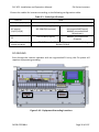
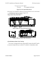
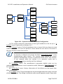
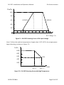
1.0: Overview
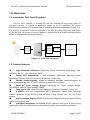
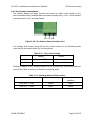
1.1 Inverter for Grid-Tied PV Systems
The PVI 36TL inverter is suitable for use for commercial and large scale PV
grid-tied systems. A system is generally made up of PV modules, DC power
distribution equipment, PV inverter and AC power distribution equipment (Figure 1.1).
The inverter converts DC from PV modules to AC with the same frequency and phase
as the AC grid. All or part of the AC power is supplied to local loads, and the surplus
power is supplied to the electricity grid.
DC power
AC power
distribution
distribution
equipments
equipments
Bidirectional
electric meter
AC Grid
Figure 1.1 - Grid-Tied PV System
1.2 Product Features
High Conversion Efficiency: Advanced 3-level conversion technology; Max.
efficiency: 98.4%;CEC efficiency: 98.0%
Strong Grid Adaptability: 7 grid standards applicable; Reactive power
adjustable; Power Factor (PF) value: ±0.8, Remote Curtailment
Flexible Communication: Supports standard Modbus communications to
rd
ensure compatibility with 3 party monitoring and control systems
Wide DC Input Voltage Range: Operating DC Input Voltage Range:
200-950Vdc; Max DC input voltage: 1000V
Long Service Life: Uses thin-film capacitors to extend inverter’s service life
2 MPPTs: Dual and independent MPPT (Maximum Power Point Tracking)
enable maximum design flexibility and optimize energy harvest over the life of the
system
High Protection Degree: NEMA 4X protection degree meets the needs of both
indoor and outdoor use;
Intelligent Integration: Embedded DC/AC switches and up to 8 fused string
inputs eliminates the need for external combiner boxes and simplifies installation.
DOCR-070588-A
Page 7 of 107
PVI 36TL Installation and Operation Manual
PVI Series Inverters
1.3 Product Protection Functions
Reverse polarity protection of DC input
Short circuit protection
Arc-Fault Circuit Interruption
Anti-islanding protection
Input and output over-voltage protection
Input over-current protection
Monitoring of DC input insulation against ground
Monitoring of AC output voltage and frequency
Monitoring of Leakage current against ground
Monitoring of DC injection from AC output
Monitoring of ambient temperature
Monitoring of IGBT module temperature
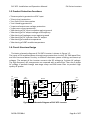
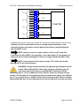
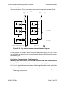
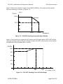
1.4 Circuit Structure Design
The basic schematic diagram of PVI 36TL inverter is shown in Figure 1.2.
The input of PV modules passes through surge protection circuitry, DC EMI wave filter,
and the front-end boost circuitry to achieve maximum power tracking and boost up
voltages. The output of the inverter converts the DC voltage to 3-phase AC voltage.
The high frequency AC components are removed with a wave filter. Then the 3-phase
AC voltage is passed through two-stage relays and EMI wave filter to produce high
quality AC power.
PV
Input Fuses
PV1+
PV1+
PV1+
PV1+
DC
Switch
MPPT1
AC
Switch
PV1+
PV1-
PV1PV1PV1PV1-
AC
Output
N
L1
L2
MPPT2
PV2+
PV2+
PV2+
PV2+
PV2+
PV2-
PV2PV2PV2PV2-
L3
Three level
inverter
PE
AFD
Figure 1.2 - Schematic Diagram of PVI 36TL Inverter
DOCR-070588-A
Page 8 of 107
PVI 36TL Installation and Operation Manual
PVI Series Inverters
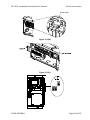
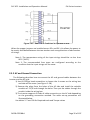
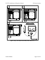
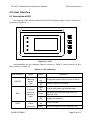
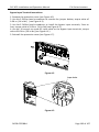
1.5 Appearance Description
3
1
4
4
2
9
8
5 6 7
Figure 1.3 - Sketch of PVI 36TL Inverter
Main Items of the Inverter:
1) Main inverter section
2) Wiring box of the inverter
3) Mounting bracket
4) External cooling fans
5) LED indication lights
6) LCD
7) Key buttons
8) DC switch: DC power on/off
9) AC switch: AC power on/off
1.6 Anti Islanding
This inverter includes Active Anti-Islanding detection as required by
UL1741/IEEE1547. The inverter will automatically make small variations in reactive
power output in order to detect a possible islanding condition. If the grid is stable,
these small variations will have negligible effects on system voltage and frequency.
DOCR-070588-A
Page 9 of 107
PVI 36TL Installation and Operation Manual
PVI Series Inverters
However, in an islanded condition the small amount of reactive power changes will
force the system voltage or frequency to change significantly, which will trigger the
inverter to shut down.
1.7 DC Ground Fault Protection
The PVI 36TL includes residual current detection as part of the DC ground fault
detection method as required by UL1741. If there is a ground fault in the array, the
ground fault detection technology will detect the array leakage current. The
inverter will shut down if the leakage current exceeds 500mA.
1.8 Surge Suppression
STANDARD WAVEFORM PEAK VALUES
Surge Category
Ring Wave
Combination Wave
B
6 kV/0.50 kA
6 kV/3 kA
"Standard 1.2/50 μs - 8/20 us Combination Wave"
"Standard 0.5 μs - 100 kHz Ring Wave"
1.9 DC Arc Fault Detection
The PVI 36TL includes DC Arc fault detection compliant with UL 1699B. The inverter
detects electrical noise that typically accompanies a DC series arc. The inverter will
shut down should the arc fault sensor detect a series arc. See section “Arc fault
current interruption” for more details.
2.0: Installation
Below is the installation procedure for the inverter. Please read carefully and install the
product step-by-step.
Before installation, please check that the following items are included in the package:
Table 2.1 - Main Items
No.
Item
(1)
Main inverter
section
DOCR-070588-A
Qty
Note
1
Page 10 of 107
PVI 36TL Installation and Operation Manual
PVI Series Inverters
(2)
Wiring box
1
(3)
Mounting bracket
1
Upon which inverter is hung and
mounted onto a wall
(4)
User manual
1
Installation and operation manual
(5)
Accessory kit
1
Contains all necessary accessories
The (5) Accessory kit contains items listed below:
Table 2.2 - Accessories
No.
Item
(1)
M8 Expansion tubes
8
For mounting bracket
(2)
M8×25 assembling
bolts
8
For mounting bracket
(3)
M6 X16 screw
6
For wiring box and main section; 2
spare parts
(4)
M5X10 screw
10
8 for mounting bracket and inverter,
external ground connection; 2 for
installing jumper busbar.
(5)
M5 flange nut
2
For internal ground stud connection; 1
spare part
(6)
Lifting eye nut M10
2
For lifting the main section
(7)
OT type terminal
2
For ground connection
5
For AC output cables, 1 spare part
8
For AC ground cables
20
For DC input cables, 4 spare parts
(8)
(9)
(10)
Pre-insulated end
ferrule for AC side
(4 AWG)
Pre-insulated
end
ferrule for grounding
(8AWG)
Pre-insulated end
ferrule for DC side
(10 AWG)
DOCR-070588-A
Qty
Note
Page 11 of 107
PVI 36TL Installation and Operation Manual
PVI Series Inverters
(11)
RJ45 connecter
4
For RS-485 or Ethernet communication,
2 spare parts
(12)
5 pin connector
1
For RS-485 communication
(13)
3 pin connector
1
For dry contact communication
(14)
Jumper busbar
2
For parallel mode use
INSTRUCTION:
The items in the accessory kit table above are for the standard
configuration. The accessories may vary if optional parts are purchased.
2.1 Recommendations before Installation
Check that the product environmental specifications (protection degree,
operating temperature range, humidity and altitude, etc.) meet the requirements of
the specific project location;
Make sure that the AC grid voltage is within the normal range.
Ensure that the local electricity supply authority has granted permission to
connect to the grid.
Installation personnel must be qualified electricians or people who have
received professional training.
Sufficient space according to Figure 2.3 should be provided to allow the
inverter cooling system to operate normally.
Install the inverter away from flammable and explosive substances.
Avoid installing the inverter in locations that exceed the temperature limits
specified in the inverter data sheet to limit undesirable power loss.
Do not install the inverter near the electromagnetic source which can
compromise the normal operation of electronic equipment.
DOCR-070588-A
Page 12 of 107
PVI 36TL Installation and Operation Manual
PVI Series Inverters
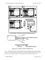
2.2 Mechanical Installation
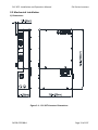
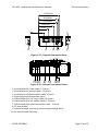
1) Dimensions
Figure 2.1 - PVI 36TL Inverter Dimensions
DOCR-070588-A
Page 13 of 107
PVI 36TL Installation and Operation Manual
PVI Series Inverters
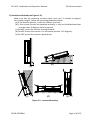
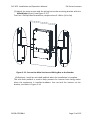
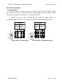
2) Installation Method (see Figure 2.2):
Make sure that the mounting structure (wall, rack, etc.) is suitable to support
the inverter weight. Follow the mounting guidelines below:
(a) If the location permits, install the inverter vertically.
(b) If the inverter cannot be mounted vertically, it may be tilted backward but
no lower than 15 degrees from horizontal.
(c) Do NOT mount the inverter leaning forward.
(d) Do NOT mount the inverter in a horizontal position (<15 degrees).
(e) Do NOT mount the inverter upside down.
(b)
(a)
(c)
(d)
(e)
Figure 2.2 - Inverter Mounting
DOCR-070588-A
Page 14 of 107
PVI 36TL Installation and Operation Manual
PVI Series Inverters
NOTICE:
When the inverter is mounted at an angle ≤15° outdoor, shade cover is
recommended to be installed above the inverter to avoid direct
sunlight.
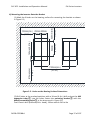
3) Installation Space Requirement (see Figure 2.3):
The distances between the inverters or the surrounding objects should meet
the following conditions:
NOTICE:
The spacing between two adjacently mounted inverters should be
≥500mm (19.7 inches). Ensure that the air space around the inverter is
well ventilated.
Figure 2.3 - Inverter Wall Mounting Specifications
NOTICE:
The installation clearance between two inverters needs to be increased
to 30 in. when the ambient temperature is higher than 45°C.
DOCR-070588-A
Page 15 of 107
PVI 36TL Installation and Operation Manual
7.9in
¡Ý
200mm
PVI Series Inverters
23.6in
¡Ý
600mm
11.8in
¡Ý
300mm
11.8in
¡Ý
300mm
11.8in
¡Ý
300mm
Figure 2.4 - Inverter Pillar Mounting Specifications
INSTRUCTION:
If the inverter is installed on Unistrut or the array racking (instead of
solid wall), the space from the bottom of one inverter to the top of the
inverter below may be as small as 4in (100mm).
DOCR-070588-A
Page 16 of 107
PVI 36TL Installation and Operation Manual
PVI Series Inverters
813mm(min.)
(32in.)
522mm
(20.55in.)
140mm(5.51in.)
550mm(min.) 250mm 250mm
(21.7in.) (9.84in.)(9.84in.)
425mm(min)
(16.7in.)
4) Mounting the Inverter Onto the Bracket
(1) Mark the 8 holes on the bearing surface for mounting the bracket as shown
in Figure 2.5;
1100mm(min.)
(43.3in.)
Figure 2.5 - Holes on the Bearing Surface Dimensions
(2) Drill holes at the marked positions with a 10mm (0.4in.) drill and put the M8
expansion tubes① into the holes; fasten the mounting bracket② with the
M8x25 assembling bolts③ in the accessory kit. Figure 2.6.
Tool: Electric drill (Ф10mm/0.4in. head), 13mm wrench 240 in-lbs
DOCR-070588-A
Page 17 of 107
PVI 36TL Installation and Operation Manual
PVI Series Inverters
1
2
2
3
3
5.51in.
(140mm)
1
20.55in.
(522mm)
9.84in. 9.
(250mm) (2 84in.
50mm)
Figure 2.6 - Securing the Mounting Bracket
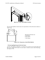
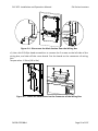
(3) Hang the inverter onto the mounting bracket as shown in Figure 2.7 and
Figure 2.8;
Lift mounting: Take out the lifting eye nut M10 (2pcs) from the accessory kit,
and screw them onto the studs at the top of the inverter. Use a sling rope or
bar (inserted through both lifting eye nuts) to lift the inverter onto the
bracket. The minimum angle between the two sling ropes should be less
than 90 degrees.
Manual mounting: Two people are needed to properly lift the inverter by the
handles detailed in Figure 2.8, and mount the inverter onto the bracket.
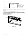
CAUTION:
The main PVI 36TL inverter section is 55kg (≈122 pounds).
Please ensure the mounting bracket is properly installed before
hanging the inverter on the bracket. It is recommended to have at
least 2 people to mount the inverter due to the weight of the
equipment.
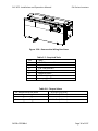
Figure 2.7 - Mounting the Main Inverter Section on the Bracket
DOCR-070588-A
Page 18 of 107
PVI 36TL Installation and Operation Manual
PVI Series Inverters
Figure 2.8 - Grab Handle Position
(4) Installing the wiring box
① Remove the cover plate at the bottom of the main section. (see Figure 2.9)
Tool: No.2 Phillips head screwdriver
Figure 2.9 – Main Section Cover Plate
② Remove the cover at the top of the wiring box (see Figure 2.10)
DOCR-070588-A
Page 19 of 107
PVI 36TL Installation and Operation Manual
PVI Series Inverters
Figure 2.10 - Wiring Box Cover
③Connect the wiring box to the main section, using M6x16 screws (4pcs) to
secure the wiring box. (see Figure 2.11)
Tool: No. 10 Wrench, torque value of 25 in-lbs (2.8N.m )
Figure 2.11 - Wiring Box Installation
CAUTION:
The total weight of the PVI 36TL main inverter section and wiring box is
66kg (146 pounds).
DOCR-070588-A
Page 20 of 107
PVI 36TL Installation and Operation Manual
PVI Series Inverters
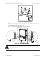
(5) Attach the main section and the wiring box to the mounting bracket with the
M5x10 bolts (6 pcs). (see Figure 2.12)
Tool: No.2 Phillips head screwdriver, torque value of 1.6N.m (14 in-lbs)
Figure 2.12 - Secure the Main Section and Wiring Box to the Bracket
(6) Optional - Install an anti-theft padlock when the installation is complete.
The anti-theft padlock is used to help prevent the inverter from being stolen
when the equipment is installed outdoors. You can lock the inverter on the
bracket, as shown in Figure 2.14:
DOCR-070588-A
Page 21 of 107
PVI 36TL Installation and Operation Manual
PVI Series Inverters
Figure 2.13 - Anti-Theft Padlock Location
The anti-theft padlock should meet the requirement of the dimensions shown in
Figure 2.14:
B
C
A
Recommended lock size:
A: Ф3~6mm
B: 20~50mm
C: 20~50mm
Figure 2.14 - Dimensions of Anti-Theft Padlock
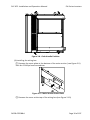
5) Removing/Replacing the Wire Box Cover:
(1) Use a #3 Phillips screwdriver to remove the 4 screws on the wiring box and
pull cover straight off the box. Do not twist or slide the cover while removing.
(see Figure 2.15)
DOCR-070588-A
Page 22 of 107
PVI 36TL Installation and Operation Manual
PVI Series Inverters
Figure 2.15 – Removing the Wiring Box Cover
(2)To replace the cover use a #3 Phillips screwdriver to replace the 4 screws on the
cover.
INSTRUCTION:
It is important to use a hand tool (e.g. Screwdriver or T-handle, #3
Phillips) and not power drivers or other types of screw drivers. Also, it is
important to hold the cover in alignment with balanced force across the
cover, not weighted toward any edge. Partially engage all four screws to
the threaded inserts a few rotations before tightening any one screw.
This is important to maintain alignment and avoid thread damage. When
all four screws are engaged torque to 20 in-lbs (2.2Nm ).
DOCR-070588-A
Page 23 of 107
PVI 36TL Installation and Operation Manual
PVI Series Inverters
2.3 Electrical Installation
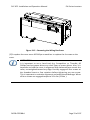
The connection interface of PVI 36TL inverter:
Figure 2.16 - Full View of Wiring Box with Options
DOCR-070588-A
Page 24 of 107
PVI 36TL Installation and Operation Manual
PVI Series Inverters
20.7in(525mm)
19.1in(485mm)
18.7in(475mm)
14.8in(377mm)
5.4in
(137mm)
10.1in
(257mm)
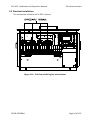
7
DC INPUT
AC OUTPUT
COMM. PORT
WARNING:
High touch current .
Earth connection essential
before connecting supply.
For more details please
see the user manual.
5
1
2
3 4
6
Figure 2.17 - External Connection Ports
8 9 8
8
8
9 10
Figure 2.18 - Internal Connection Points
1. Knockout for DC input cable, 1-1/4inch
2. Knockout for AC output cable, 1-1/4inch
3. Knockout for communication cable, 3/4inch
4. External ground connection point
5, Side knockout for DC input cable,1-1/4inch
6. Side knockout for AC output cable, 1-1/4inch
7. Side knockout for communication cable,3/4inch
8. DC fuse holder
9. Internal ground connection point and grounding studs.
10. AC output terminal block
DOCR-070588-A
Page 25 of 107
PVI 36TL Installation and Operation Manual
PVI Series Inverters
Choose the cables for inverters according to the following configuration table:
Position
DC input (﹢/﹣)
AC output
(L1/L2/L3/N)
PE
RS-485
communication
Table 2.3 - Cable Specifications
Cable
DC cables specifications refer to Table3-6
#6~1AWG(Copper)
#4~1AWG(Aluminum)
#10~6AWG(Copper)
#6AWG
recommended(Copper)
#4AWG recommended
(Aluminum)
#8AWG recommended
(Copper)
UTP CAT-5e or 3x#22~18AWG communication cable (eg.
Belden 3106A)
DC GROUND
Even though the inverter operates with an ungrounded PV array, the PV system still
requires equipment grounding.
Figure 2.19 - Equipment Grounding Locations
DOCR-070588-A
Page 26 of 107
PVI 36TL Installation and Operation Manual
PVI Series Inverters
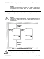
2.3.1 DC Connection
1) Working Mode
PVI 36TL inverter has two PV input sections: DC Input-1 and DC Input-2. These
two sections can work in “Parallel mode” or “Independent mode” (see Figure 2.20).
The default setting from the factory is “Independent mode”.
In Parallel mode, the two PV input sections share one MPP Tracker; In
Independent mode, each PV input section works with independent MPP Tracker.
Inverter
Inverter
DC
Input-1
n1
DC
Input-2
n2
n3
n1=n2 =n3=n4
n4
Figure 2.20(a) - Parallel Mode
DOCR-070588-A
DC
Input-1
n1
n2
n1=n2
DC
Input-2
n3
n4
n3=n4
Figure 2.20(b) - Independent Mode
Page 27 of 107
PVI 36TL Installation and Operation Manual
Inverter model
PVI 36TL
PVI Series Inverters
Table 2.4 - DC Input Power Specification
Max. DC input power
Rated DC input power of
(Parallel mode)
each input section
(Independent
modeDefault from factory)
37kW (70A)
18.5kW (35A)
Note: The standard configuration is “Independent mode”. If it needs to switch to
the “Parallel mode”, please take the following steps to change the internal
configuration:
1. Remove the cover of the wiring box. (see Figure 2-15)
2. Remove the protection cover. (see Figure 2.21a)
3. Use No.2 Phillips head screwdriver to install the jumper busbar, torque value of
1.6N.m (14 in-lbs) (see Figure 2.21b)
4. Set the selector switch on the LCD board (see Figure 2.22) to parallel mode.
5. Reinstall the protection cover.
Figure 2.21(a)
DOCR-070588-A
Page 28 of 107
PVI 36TL Installation and Operation Manual
PVI Series Inverters
Jumper busbar
Figure 2.21(b)
Figure 2.21(c)
PAR
IND
S401
ON
OFF
S403
DOCR-070588-A
S402
Page 29 of 107
PVI 36TL Installation and Operation Manual
PVI Series Inverters
Selector switch for PV
connection mode
1-----independent mode
2-----parallel mode
Figure 2.22 – PV Connection Mode Selector Switch Location
2) DC Fuse Configuration
PVI 36TL inverters are equipped with standard 15A DC fuses. Customers must verify
that the appropriate fuses are installed depending on the actual configuration of PV
strings.
(a) Each independent string of DC input from the PV strings needs fuse
protection.
(b) The rated voltage of fuses should 1000V
(c) The rated current of fuses is generally 1.56 × short circuit current from the PV
strings, rounded up to the next available fuse size.
The following table lists the fuse type, specifications and number under the rated
voltage and power range of 8 strings of PV panels.
Brand
36
kW
Standard fuses
20A
25A
30A
SPF015
SPF020
SPF025
SPF030
15A/1000V
20A/1000V
25A/1000V
30A/1000V
Littelfuse
Table 2.5 - DC Fuse Selection
Note 1: The 1000VDC Littelfuse KLKD fuse series are recommended. The detailed
information is available for customers to find and download from
http://www.littelfuse.com/.
Note 2: The fuse holders can also accept a 20A (SPF020), 25A (SPF025) and a 30A
(SPF030) fuse for combined input strings if needed. Two 30A fuses should not be used
next to each other. Note Solectria doesn’t provide these fuses, but customer can
replace with the appropriate fuse in field.
WARNING: Use of different fuses or wrong sized fuses can cause
damage to equipment or create un-safe working conditions.
DOCR-070588-A
Page 30 of 107
PVI 36TL Installation and Operation Manual
PVI Series Inverters
3) DC Cable Connection
To ensure the optimum performance of the inverter, please read the following
guidelines before DC connection:
(a) Confirm the DC configuration referring to Table 2.5 and ensure that the
maximum open circuit voltage of the PV modules is lower than 1000 VDC
under any conditions.
(b) Confirm that the PV strings for each MPPT of the inverter are of the same
type and specification before connection. The number, orientation, and tilt
of PV strings may differ for different applications.
(c) Configure the external wiring according to the conditions in table 2.6:
WARNING: Working with live voltage is dangerous. It is
recommended to have all live circuits disabled prior to
performing connections.
Table 2.6 - DC Input Configuration
DC
Inputs
10
9*
8
7*
6
5*
4
2
1*
Configuration
Using Y**
connectors
Using a Y**
connector
Standard use of
wiring box
fuses
Standard use of
wiring box
fuses
Standard use of
wiring box
fuses
Standard use of
wiring box
fuses
Standard use of
wiring box
fuses
Use of Bypass
terminals
Use of Bypass
terminal
DOCR-070588-A
Max. DC
Wire Size
4 AWG
Conductors
Torque
30 in-lbs
Fuse Type
4 AWG
30 in-lbs
PV Fuse
4 AWG
30 in-lbs
PV Fuse
4 AWG
30 in-lbs
PV Fuse
4 AWG
30 in-lbs
PV Fuse
4 AWG
30 in-lbs
PV Fuse
4 AWG
30 in-lbs
PV Fuse
2 AWG
50 in-lbs
2 AWG
50 in-lbs
Bypass
terminals
Bypass
terminal
PV Fuse
Page 31 of 107
PVI 36TL Installation and Operation Manual
PVI Series Inverters
*Consider combining MPPT zones for such configurations
**Use Inline fuses to adhere to module series fuse rating if necessary
Note: When using Y connectors to combine two strings you have to use a UL
listed parts such as: Amphenol Overmolded Solar Junction. When
combining 2 strings you should use a Y connector that has a fuse in each
branch equal to the module series fuse rating. For 9 inputs you can place
the 30A fuse in any fuse holder. For 10 inputs you should place one 30A
fuse in each MPPT zone even if they are running in parallel mode. Two 30A
fuses should never be next to each other.
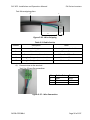
(d) Check the polarity (Figure 2.23) before plugging the DC connectors with the
cables of PV strings according to the following steps:
i. Use a multi-meter to measure the PV strings’ cable ends and check the
polarity.
ii. The positive (+)terminal of cable should match the positive (+) terminal of
inverter’s DC input.
iii. The negative (-) terminal of cable should match the negative (-) terminal of
inverter’s DC input.
NOTICE:
It is important to use a multi-meter to check the polarity of DC input
cables to avoid any risk of reverse polarity.
Figure 2.23 - Polarity Check
(e) Remove the plug from the holes of the DC side and plug the suitable
conduits of 1-1/4 inch through the knockouts. Then put the cables through
the conduits inside the wiring box.
(f) Crimp the DC cables with the attached pre-insulated end ferrule (16Pcs) by
using the crimping pliers. (see Figure 2.25)
Tools: Diagonal pliers, wire stripping pliers, crimping pliers
DOCR-070588-A
Page 32 of 107
PVI 36TL Installation and Operation Manual
PVI Series Inverters
Figure 2.24 - DC Input Cables Set Up
(g) Connect the crimped DC cables to the terminal block on the circuit board
and fasten the screws, as shown in Figure 2.25:
Tools: 6mm (0.23in.) flat screwdriver
Torque value: 3.4N-m (30 in-lbs)
Figure 2.25(a) - DC Input Cable Specifications
Figure 2.25(b) - DC Input Cable Connections
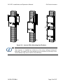
4) Dual Maximum Power Point Tracking
The inverter is designed with two separate MPP Trackers (Dual MPPT) which
can operate independently or combined. The default is independent mode.
DOCR-070588-A
Page 33 of 107
PVI 36TL Installation and Operation Manual
PVI Series Inverters
1
2
PV1+
3
IN1+
4
1
2
PV2 +
Inv 2+
3
4
1
2
PV1-
3
Inverter
Inv 1-
4
1
2
PV2-
IN2-
3
4
Figure 2.26 - Two MPPTs Operating Independently
Independent mode can be very helpful for sites with shading on parts of the array.
However, this also means that one must consider these two zones as two
separate inverters and power must be balanced as much as possible between
the two MPPT zones.
NOTE: Always connect an equal number of wires to PV1 and PV2
connectors for dual MPPT zone operation. If an odd number of connections are
required, we recommend setting the inverter to single (combined) MPPT zone.
NOTE: Connecting all of the inputs at zone “PV1” will result in only
utilizing 50% of the inverter power
WARNING: Strings must be balanced for optimum performance and AC
output. When doing DC/AC ratio sizing, perform calculations on the
zone level unless you intend to combine MPPT. Maximum DC/AC
oversizing ratio is 1.5 STC conditions of the modules. Each zone maximum input
power is 27 kW. Note for any application that may experience higher than 1000 W
2
per m on a regular basis, a smaller DC/AC ratio is recommended. Failure to follow
those guidelines may result in damage to the inverter and may void your warranty.
DOCR-070588-A
Page 34 of 107
PVI 36TL Installation and Operation Manual
PVI Series Inverters
Figure 2.27 - Two MPPTs Combined to Operate as One
When the copper jumpers are installed across DC+ and DC- this allows the power to
be evenly distributed between the two trackers such as applications of odd number
of strings.
Note 1: The temperature rating of the input wirings should be no less than
90°C (194°F).
Note 2: The recommended fuse types are configured according to the
condition that the input strings are the same.
2.3.2 AC and Ground Connection
The following describes how to connect the AC and ground cables between the
inverter and the AC grid:
1) Use #3 Phillips head screwdriver to loosen the 4 screws on the wiring box
and take off the cover. (see Figure 2.-28)
2) Remove the plugs from the holes of the AC side and install the suitable
conduits of 1-1/4 inch through the holes. Then put the cables through the
conduit inside the wiring box.
3) The inverter supports 3 kinds of cable connection on the AC side depending
on the grounding connection method. The cable set-up procedures are
illustrated below.
Use tables 2.-7 and 2.8 for Required tools and Torque values
DOCR-070588-A
Page 35 of 107
PVI 36TL Installation and Operation Manual
PVI Series Inverters
Figure 2.28 - Remove the Wiring Box Cover
No.
1.
2.
3.
4.
5.
6.
7.
Table 2.7 - Required Tools
Tools
#3 Phillips screwdriver
1/4” flat head bit
1/8” flat head bit
Torque driver
Diagonal pliers
Wire stripping pliers
Crimping pliers
Table 2.8 - Torque Values
AC output terminal block
Internal grounding bar
Internal grounding stud
External grounding point
DOCR-070588-A
30 in-lbs (3.5 N-m )
14 in-lbs (1.6 N-m )
14 in-lbs (1.6 N-m )
14 in-lbs (1.6 N-m )
Page 36 of 107
PVI 36TL Installation and Operation Manual
PVI Series Inverters
COMM. PORT
WARNING:
High touch current .
Earth connection esse
before connecting sup
For more details please
see the user manual.
Figure 2.29(a) - AC Output and Ground Cable Connections
DOCR-070588-A
Page 37 of 107
PVI 36TL Installation and Operation Manual
PVI Series Inverters
COMM. PORT
WARNING:
High touch current .
Earth connection esse
before connecting sup
For more details please
see the user manual.
Figure 2.29(b) - AC Output and Ground Cable Connections
Pre-insulated end ferrule
4pcs
Core wire
Pre-insulated end ferrule
Figure 2.30 - AC Output and Ground Cable Set Up
(1) Connect the AC (L1, L2, L3) cables to the terminal block and use the OT type
terminal to connect the ground cable to the internal grounding stud inside the wiring
nd
box. (see the 2 graph in Figure 2.27) Set up the cables referring to Figure 2.29.
DOCR-070588-A
Page 38 of 107
PVI 36TL Installation and Operation Manual
PVI Series Inverters
Pre-insulated end ferrule
3pcs
OT type terminal,1pcs
Core wire
Pre-insulated end ferrule
Core wire
OT type terminal
Figure 2.31 - AC Output and Ground Cable Set Up
(2) Connect the AC (L1, L2, L3) cables to the terminal block and use the OT type
terminal to connect the ground cable to the external grounding point at the bottom of
rd
the wiring box. (see the 3 graph in Figure 3-27 ) Set up the cables referring to Figure
2.30.
Pre-insulated end ferrule
3pcs
Core wire
Pre-insulated end ferrule
Ground wire
OT type terminal,2pcs
Figure 2.31 - AC Output and Ground Cable Set Up
INSTRUCTION:
The attached pre-insulated end ferrules match with the #6AWG cables. If
a different gauge is selected, a different pre-insulated end ferrule will
need to be provided by the installers.
DOCR-070588-A
Page 39 of 107
PVI 36TL Installation and Operation Manual
PVI Series Inverters
4) When the output of the inverter is connected to the grid, an external AC
circuit breaker is required to be installed to safely disconnect the inverter from the
grid when overcurrent occurs.
5) The Grid connection type could be optional, which can be (L1,L2, L3,N,PE)
or(L1,L2, L3,PE) .
Either 3 pole or 4 pole AC circuit breaker should be selected as per the following
specifications:
Table 2.9 - AC Breaker Selection Selection
Inverter
AC breaker rated current(A)
PVI 36TL
60
Acceptable Transformer Configurations:
Inverter side
Grid Side
Delta
Wye-grounded
Delta
Delta
Wye-grounded
Delta
Wye-grounded
Wye-grounded
When interfacing with a Wye-grounded transformer winding, a neutral is required.
Since the neutral is used by the inverter for voltage sensing, the neutral does not carry
full load amps. The size of the neutral may be reduced to a conductor no smaller than
the EGC.
When installing multiple inverters for parallel operation connected to a single
transformer the KVA rating of the transformer must be at least 5% greater than the
total inverter kVA rating that feed the transformer. Up to 70 inverters may be
connected in parallel for use with a single transformer.
DOCR-070588-A
Page 40 of 107
PVI 36TL Installation and Operation Manual
PVI Series Inverters
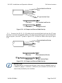
2.4 Inverter Communication Connections
The PVI 36TL inverters support industry standard Modbus RS-485 communications.
PAR
IND
S401
ON
OFF
S403
S402
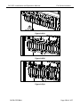
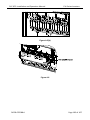
Figure 2.32 - Communication/LCD and Component Locations Inside the Wiring Box
DOCR-070588-A
Page 41 of 107
PVI 36TL Installation and Operation Manual
Item
Picture
1
PVI Series Inverters
Configuration description
P205 - Dry Contact Communication Port (3 Pin
Connector)
Please see section 2.4.3 Dry contact communication for
more details.
N.O. N.C. COM
2
P207 - USB port
Reserved for factory use
3
P204 - Not Used
4
P203 - Not Used
5
P208 - Modbus (RS-485) connector
1 - NC
2 - NC
3 - RS-485+
4 - RS-4855 - NC
6
S403 - Not Used
7
S402 - Selector switch for the 120Ω Modbus RS-485
termination resistor
1 - Disable the RS-485 bus termination
2 - Enable the RS-485 bus termination
8
S401 - Selector switch for setting the PV
connection mode
1 - Independent mode
2 - Parallel mode
See section 2.3.1 for more details
Table 2.10 - Communication Connections and Configuration Switches
DOCR-070588-A
Page 42 of 107
PVI 36TL Installation and Operation Manual
PVI Series Inverters
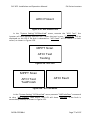
2.4.1 Modbus (RS-485) Network Connections with External Monitoring
Systems
The PVI 36TL inverter can be connected to an external Data Acquisition System (DAS) via
Modbus (RS-485) connection as shown in figure 2.33.
Figure 2.33 - PVI 36TL Inverters in a Modbus (RS-485) Daisy Chain Connected to an
External DAS
When connected to an external Data Acquisition System (DAS), Solectria PVI 36TL
inverters support up to 32 inverters/devices on the Modbus (RS-485) daisy chain. The
Inverter Modbus IDs are configurable from 1 to 128.
Solectria recommends that the Modbus (RS-485) daisy chain for PVI 36TL inverters is
limited to a maximum length of 1600 ft. (500m).
Care must be taken when daisy chaining the inverters as shown above, utilizing a
Shielded Twisted Pair Modbus cable such as Belden 9841.
The shield continuity should be maintained for the entire length of the daisy chain and
should only be connected to ground (GND) at the Data Acquisition System (DAS). The
shield should not be connected to any of the inverters to prevent any possible ground
loops.
It is important to terminate the Modbus (RS-485) bus correctly to minimize any noise
and reflections. The bus should be terminated at the source (the DAS) and at the last
Modbus device in the daisy chain, typically an inverter. The PVI 36TL Modbus
termination is turned on by flipping switch S402 to the ON position as shown in Figure
DOCR-070588-A
Page 43 of 107
PVI 36TL Installation and Operation Manual
PVI Series Inverters
3-35. S402 should always be left in the off position except for the last inverter in the
daisy chain.
Star or T Modbus (RS-485) network topologies should always be avoided. See Figure
2.34.
Figure 2.34
It is important to daisy chain the inverter Modbus (RS-485) connections to minimize
noise and bus reflections. Any network topologies shown to the left should be
avoided. Equivalent daisy chain topologies shown to the right should be used instead.
DOCR-070588-A
Page 44 of 107
PVI 36TL Installation and Operation Manual
PVI Series Inverters
Connecting External DAS Modbus (RS-485) Network to the PVI 36TLInverter:
Warning: Risk of Electric Shock.
Make sure all DC and AC power to the unit has been disconnected before opening
the inverter wiring box and make sure hazardous high voltage and energy
inside the equipment has been discharged.
1. Open the inverter wiring box.
2. Bring the cable into wiring box through knockout holes at the bottom.
3. Connect the Modbus (RS-485) wires to the green Phoenix connector (P208) ensuring
correct polarity and using a twisted pair in the shielded twisted pair cable.
4. If the inverter is the last Modbus device in the daisy chain, make sure the Modbus
termination switch S402 is in the ON position (Up towards the LCD) enabling Modbus
termination. Do not turn the switch to the ON position in any other inverters in the
daisy chain.
S402 - Selector switch for
the 120Ω RS-485 termination
resistor
1 - Disable the Modbus
(RS-485) bus termination.
(Factory default)
2 - Enable the Modbus
(RS-485) bus termination
(Applies only for the last
inverter in the daisy chain)
Note that switch S403 to the
left of S402 not used and
stays in the OFF position.
Figure 2.35 - The Modbus (RS485) Termination Switch (S402) Location and Settings on the
LCD/Communication Board.
DOCR-070588-A
Page 45 of 107
PVI 36TL Installation and Operation Manual
PVI Series Inverters
Figure 2.36
The above image shows the Modbus (RS-485) cable connection where the Modbus daisy chain
ends. Notice how the cable shield is not landed inside the inverter. The Modbus termination
switch (S402) is in the on position.
5.
IMPORTANT: The cable shield should only be connected to ground (GND) at the external
DAS. Do not connect the shield to any of the inverters
DOCR-070588-A
Page 46 of 107
PVI 36TL Installation and Operation Manual
PVI Series Inverters
Figure 2.37
Notice how the cable shield is daisy chained together and not landed inside the inverter. S402
is in the OFF position, or down towards the Phoenix connector when the inverter is in the
middle of the daisy chain.
Warning: Risk of Electric Shock.
Make sure all shield wires are properly secured and insulated to prevent shorting to
any other components inside the inverter.
6.
7.
8.
Close the wiring box.
Reconnect AC and DC power and turn the inverter on when it is safe.
Configure the Inverter Modbus ID and Baud rate.
DOCR-070588-A
Page 47 of 107
PVI 36TL Installation and Operation Manual
PVI Series Inverters
2.4.2 Modbus (RS-485) Network Connections with SolrenView Data Logger
If the PVI 36TL inverters are ordered with SolrenView data monitoring services from the
factory, the SolrenView data logger is installed in the factory in one of the inverters. This
inverter should be installed as Inverter number 1 in the Modbus daisy chain as shown in
Figure 2.38.
Figure 2.38 - Typical PVI 36TL Network Connections Utilizing SolrenView Data Logger
For information how to install the SolrenView data logger inside the PVI 36TL inverter see
the “SolrenView Installation Guide for PVI 14-36TL Inverters” (DOCR-070580-A) document
available on the Solectria document website.
DOCR-070588-A
Page 48 of 107
PVI 36TL Installation and Operation Manual
PVI Series Inverters
Connecting the Ethernet Router/Firewall to the SolrenView Data Logger:
The SolrenView Data logger is connected to the customer provided Ethernet router/firewall
utilizing a Cat 5e or better Ethernet cable as shown in figure 2.38.
The Ethernet cable length must be kept shorter than 328ft (100m) to ensure trouble free
communications.
Figure 2.39. - SolrenView Data Logger Connections.
Connect the Ethernet cable to the RJ45 port on the SolrenView data logger before mounting it
inside the wiring box.
Router/Firewall Configuration:
The router/firewall should not require any special configuration as most routers are already
configured to support DHCP discovery and to allow outgoing traffic. In case the router/firewall
is configured to restrict outgoing traffic, an outgoing rule must be added to allow the logger to
connect to the SolrenView Monitoring data servers.
DOCR-070588-A
Page 49 of 107
PVI 36TL Installation and Operation Manual
PVI Series Inverters
Connecting the Modbus (RS-485) Network to the PVI 36TL Inverters with SolrenView Data
Logger:
Warning: Risk of Electric Shock.
Make sure all DC and AC power to the unit has been disconnected before opening
the inverter wiring box and make sure hazardous high voltage and energy
inside the equipment has been discharged.
The SolrenView data logger acts as the Modbus Master and can support up to 16
inverters on the Modbus (RS-485) daisy chain utilizing Modbus IDs 1 through 16. If more
than 16 inverters are required, additional SolrenView data loggers must be added, with
each logger supporting up to 16 inverters per daisy chain.
Solectria recommends that the Modbus (RS-485) daisy chain for PVI 36TL inverters is
limited to a maximum of 1600 ft. (500m).
The inverter Modbus (RS-485) connections must utilize a Shielded Twisted Pair Modbus
cable such as Belden 9841.
The cable shield continuity should be maintained for the entire length of the daisy chain
and should only be connected to Chassis GND inside the first inverter containing the
SolrenView data logger. The shield should not be connected to any of the other inverters
to prevent any possible ground loops.
Star or T Modbus (RS-485) network topologies should be avoided. See Figure 2.34.
It is important to terminate the Modbus (RS-485) bus correctly to minimize any bus
noise and reflections. The bus should be terminated at the SolrenView data logger and
at the last Modbus device in the daisy chain, typically an inverter. The PVI 36TL Modbus
termination is turned on by flipping switch S402 to the ON position as shown in Figure
2.35. S402 should always be left in the off position except for the last inverter in the
daisy chain.
1.
2.
3.
Open the inverter wiring box.
Bring the Modbus cable into the wiring box through knockout holes at the bottom.
If the inverter is the last device in the daisy chain, make sure the Modbus termination
switch S402 is in the ON position (Up towards the LCD) for Modbus termination. Do not
turn the switch to the ON position in any of the other inverters. See Figure 2.35.
The SolrenView data logger is shipped from the factory with the Modbus termination
turned ON. The two Modbus termination dip switches closest to the white Molex
connector (#3 and #4 on SW1) should be in the ON position towards the edge of the
board. (See Figure 2.40)
4.
DOCR-070588-A
Page 50 of 107
PVI 36TL Installation and Operation Manual
PVI Series Inverters
Figure 2.40 - The SolrenView Data Logger Printed Circuit Board and the Modbus
Termination Dip Switches.
5.
6.
Extend the Modbus cable shield with additional wire so that it can reach to the Chassis
GND terminal block as shown in Figure 2.41.
The wire should be soldered to the cable shield to ensure solid and reliable connection.
The shield connection should be covered with a heat shrink tubing to prevent any shorts
to other components inside the inverter.
The wire should be kept as short as possible to minimize any noise pickup.
Connect the external Modbus (RS-485) cable to the green Phoenix connector (P208),
ensuring correct polarity and using a matching twisted pair in the Modbus cable. See
Figure 2.41. Care must be taken not to disconnect the Modbus wires coming from the
SolrenView logger.
DOCR-070588-A
Page 51 of 107
PVI 36TL Installation and Operation Manual
PVI Series Inverters
Figure 2.41 - SolrenView Data Logger Installed Inside the PVI 36TL Wiring Box.
Notice how the Modbus cable shield is grounded by extending the Modbus cable
shield with a wire and connecting it to the inverter chassis GND terminal.
The external Modbus cable is connected to P208 sharing the +/- RS-485 connections
with the SolrenView data logger.
DOCR-070588-A
Page 52 of 107
PVI 36TL Installation and Operation Manual
PVI Series Inverters
7. Follow steps 5 through 8 in section 2.4.1 Modbus (RS-485) Network Connections with
External Monitoring Systems to connect other inverters in the daisy chain.
Warning: Risk of Electric Shock.
Make sure all shield wires are properly secured and insulated to prevent shorting to
any other components inside the inverter.
Configuring the SolrenView Logger:
The SolrenView logger should be connected to an active router/firewall and inverters before
the inverter containing the SolrenView logger is turned on. The SolrenView Logger will go
through self-initialization, TCP/IP DHCP discovery and inverter Modbus device discovery when
it turns on.
To verify that the SolrenView logger has discovered all the inverters in the daisy chain, navigate
the SolrenView data logger menu to the “Inverters” menu item by pressing the ENTER key. All
the discovered inverters should be listed by Modbus ID and serial numbers on the LCD.
DOCR-070588-A
Page 53 of 107
PVI 36TL Installation and Operation Manual
PVI Series Inverters
2.4.3. Dry Contact Communication
The inverter features an alarm function that opens or closes a dry contact on the
communication board. (available both as contact normally open – N.O. – and as contact
normally closed – N.C.), as shown below:
N.O. N.C. COM
Figure 2.34 - Dry Contact Communication Port
The voltage and current rating of the dry contact shown in the following table
must not be exceeded under any circumstances.
Table 2.11 - Dry Contact Rating
Voltage
Current
AC
Maximum 277 V
Maximum 3 A
DC
Maximum 30 V
Maximum 1 A
Different modes of dry contact output can be accessed by connecting different
pins of the P205 connector, as shown in following table.
Table 2.12 - Working Modes of Dry Contact
Dry contact communication port Status in fault condition
Status without fault
condition
P205: N.O. — COM
Closed
Open
P205: N.C. — COM
Open
Closed
DOCR-070588-A
Page 54 of 107
PVI 36TL Installation and Operation Manual
PVI Series Inverters
Connection Plan:
You can connect a LED or other loads to indicate the operational status of the
inverter, as shown in the following figure:
(or L
+
Line circuit Breaker( 3 A)
COM
(or L
N)
-
+
-
Line circuit Breaker( 3 A)
COM
N.C.
N.C.
N.O.
N.O.
COM
COM
N.C.
N.C.
N.O.
N.O.
COM
COM
N.C.
N.C.
N.O.
N.O.
Light on in trouble free operational
N)
Fault
In operation
In operation
Light on in error
Figure 2.35 - Dry Contact Communication Schematic Diagram
If you connect the contact port to the power distribution grid, you must install
an individual miniature circuit-breaker between the dry contact and the power
distribution grid.
Dry Contact Communication Cable Connection:
Warning: If the unit is running, turn off both disconnects and wait 5 minutes before
performing any work.
a.) Remove the plugs from holes for suitable cable conduits of 3/4 inch.
b.) Put the dry contact communication cable through the cable conduit and inside
the wiring box.
c.) Use double-layer insulated cables. Strip the cables according to the
following requirements.
DOCR-070588-A
Page 55 of 107
PVI 36TL Installation and Operation Manual
PVI Series Inverters
Tool: Wire stripping pliers
D
A
L2
L1
Figure 2.36 - Wire Stripping
Table 2.13 Cable Set-Up
Description
Position
Cable type
Value
Double-layer insulated cable
D
Outer diameter
4.5 mm~ 6 mm
A
Cross-section area of conductor
0.2 mm² ~ 0.75 mm²
L1
Length of stripped outer wire skin
Maximum 15mm
L2
Length of stripped inner wire skin
Maximum 7 mm
d.) Connect wires to the terminal.
Tool: 2 or 2.5mm flat screwdriver
No.
1
2
3
Cable Color
Red
Blue
Green
Function
N.O.
N.C.
COM
Figure 3-37 - Wire Connection
DOCR-070588-A
Page 56 of 107
PVI 36TL Installation and Operation Manual
PVI Series Inverters
e.) Plug the cable terminal into the P205 connector.
Figure 2.38 - Dry Contact Communication Cable Connection
DOCR-070588-A
Page 57 of 107
PVI 36TL Installation and Operation Manual
PVI Series Inverters
3.0: Commissioning
WARNING:
Please follow the guidelines below before on-grid operation to eliminate
possible dangers and to ensure safety.
3.1 Commissioning Checklist
3.1.1 Mechanical Installation
Make sure that the mounting bracket is secure and all the screws have been tightened
to the specified torque values.
(Please refer to 2.2 Mechanical Installation)
3.1.2 Cable Connections
(a)
Make sure that all cables are connected to the right terminals.
(b)
The appropriate cable management is important to avoid physical damage.
(c)
The polarity of DC input cables should be correct and the DC Switch should be
in “OFF” position.
(Please refer to 2.3 Electrical Installation)
3.1.3 Electrical Check
(a)
(b)
(c)
Make sure that the AC circuit breaker is appropriately sized.
Test whether the AC voltage is within the normal operating range.
Make sure the DC open circuit voltage of input strings is less than 1000V.
3.2 Commissioning Steps
Complete the checklist above before commissioning the inverter as follows:
1.) Turn on the AC circuit breaker.
2.) Turn on the DC circuit breaker.
(Skip this step if there is no circuit breaker.)
3.) Switch the DC Switch to the “ON” position. When the energy supplied by the PV
array is sufficient, the LCD of inverter will light up. The inverter will then start up with
the message “sys checking”.
4.) Set up the grid standard:
INSTRUCTION:
Please check with your local electricity provider before selecting the grid
standard. If the inverter is operated with a wrong grid standard, the
electricity provider may cancel interconnection agreement.
Putting the inverter into operation before the overall system complies
with the national rules and safety regulation of the application is not
permitted.
DOCR-070588-A
Page 58 of 107
PVI 36TL Installation and Operation Manual
PVI Series Inverters
(d)
When the inverter completes “sys checking”, the LCD shows the screen as
Figure 3.1 below. Press ENTER to the standard selection interface, as shown in Figure
3.2.
(e)
Select the corresponding grid standard and press ENTER.
Set Standard!
Figure 3.1 - Set Up Grid Standard
→1
2
3
4
Rule 21
IEEE 1547
HECO-ML
HECO-OHM
Figure 3.2 - Select Grid Standard
5.) When the LCD shows the normal operation status (Figure 3.3) and the “RUN” light
on the LED panel lights up, it indicates that the grid connection and power generation
are successful.
PV1
277
21.2
223.2
725 V
14.5A
08/12 13:10:05
PV2
720 V
14.9A
277
21.5
223.2
08/12 13:10:10
(a)
(b)
Figure 3.3 - Normal Operation Status
6.) If the inverter fails to operate normally, the “FAULT” LED will illuminate and the
error message will be displayed on the LCD.
(Please refer to 7.1.2 Troubleshoot LCD faults)
7.) Set up system time and language
Set up the system time and language according to “4.4.4 System Configuration”.
8.) To check the real time operation information, you can refer to “4.4.1 Operation
information”.
DOCR-070588-A
Page 59 of 107
PVI 36TL Installation and Operation Manual
PVI Series Inverters
4.0: User Interface
4.1 Description of LCD
The inverter’s LCD mainly consists of LCD, LED indicator lights, buzzer and 4 keys,
as shown in Figure 4.1.
POWER
RUN
GRID
FAULT
Figure 4.1 - LCD
Interpretation for the indicator lights is shown in Table 5-1 and function of the
keys is shown in Table 4.2.
Table 4.1 - LED Indication
LED Indicator
Name
POWER
Working
power
light
RUN
GRID
DOCR-070588-A
Grid-tied
operation
indication
light
Grid
status
indication
Status
Light
on
Light
off
Light
on
Flash
Light
off
Light
on
Flash
Indication
Energized (control panel starts to work)
Power supply not working
In grid-tied power generation state
Derated running status (light on 0.5s,
light off 1.6s)
In other operation status or power
supply not working
Grid is normal
Grid fault (light on 0.5s, light off 1.6s)
Page 60 of 107
PVI 36TL Installation and Operation Manual
light
FAULT
Fault
status
indication
light
Light
off
Light
on
Slow
flash
Fast
flash
Light
off
PVI Series Inverters
Power supply not working
Indicates a Fault
Indicates Alarm (light on 0.5s, light off
2s)
Protective action (light on 0.5s, light off
0.5s)
No fault or power supply not working
Table 4.2 - Definition of the Keys
Key
Description
Definition of function
Escape key
Back/end/mute
Enter key
Confirm entering the menu/confirm set
value/Switch to parameter setting mode
Up
Page up in selection menu/+1 when
setting parameters
Down
Page down in selection menu/-1 when
setting parameters
4.2 Operation State
Table 4.1 indicates the definitions of LED, i.e. indicates the information of the
inverter’s operation state. It indicates that the system is energized and under DSP
control when “POWER” lights up.
“RUN” will light up when the inverter detects that the grid connection conditions
meet the requirements and power is fed into the grid. “RUN” will blink if the grid is in
de-rated running state during the period of feeding power into the grid.
“GRID” will light up when the grid is normal during the operation of the inverter.
Otherwise, “GRID” will blink until the grid restores to normal.
“FAULT” will blink quickly as a fault (except grid fault) occurs. “FAULT” will not
turn off until the fault is eliminated. The light will blink slowly when an alarm occurs.
“FAULT” remains illuminated when an internal fault occurs.
The buzzer will give an alarm if a fault (involving power grid fault) occurs.
4.3 Interface Types
Users can perform the corresponding operations with the 4 function keys
DOCR-070588-A
Page 61 of 107
PVI 36TL Installation and Operation Manual
PVI Series Inverters
according to the indications of the LCD.
(1) The LCD interface starts with the company logo once the system is energized,
as shown in Figure 4.2.
Figure 4.2 - Logo Screen
(2) Indication of inverter operation mode:
Sys.Checking
>>>>>>
Figure 4.3 - Inverter System Check Ongoing
Standby
>>>>>>
Figure 4.4 - Inverter System in Standby Mode
PV1
730 V
14.0A
08/12 13:10:05
(a)
277
20.2
223.2
PV2
729 V
14.2A
277
20.5
223.2
08/12 13:10:10
(b)
Figure 4.5 - Default Display Interface for Normal Operation
DOCR-070588-A
Page 62 of 107
PVI 36TL Installation and Operation Manual
PVI Series Inverters
GridV.OutLim
Figure 4.6 - Fault Indication Interface
LCD will display different mode interfaces based on the operation modes of the
inverter. There are four operation modes: startup system check mode (as shown in
Figure 4.3), stand-by mode (as shown in Figure 4.4), normal operation mode (as
shown in Figure 4.5, the switching time between (a) and (b) is 5 seconds), and fault
mode (as shown in Figure 4.6).
The default indication interface mainly indicates PV voltage, PV current, grid
voltage, instant power, daily generated power and time information under normal
operation.
The fault information of the most recent / current fault will be indicated on the
LCD when the inverter is in fault mode.
4.4 Menu functions
LCD displays “default indication interface” when the inverter is in operation
mode. Press ESC in this interface to escape the default interface and enter the main
operation interface. The main operation interface is shown in Figure 4.7.
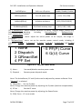
1
2
3
4
OP.Info
Alarm
History
Setting
→5 Dispatch
Figure 4.7 - Main Menus on the LCD
The users may select options with UP and DOWN, and then press ENT to confirm
selection. The users can return to the default indication interface by pressing ESC.
4.4.1 Operation information
When the cursor moves to “1 OP. Info” in the main screen, you should press ENT
to select the operation information as shown in Figure 4.8. Check the information by
pressing UP and DOWN. Return to the previous menu by pressing ESC.
DOCR-070588-A
Page 63 of 107
PVI 36TL Installation and Operation Manual
1 OP.Info
PVI Series Inverters
EDay
23.5kWh
PDayPk 19kW
DayT
12 .1 h
Uab
Ubc
Uca
Freq
480.2V
480.5V
479.7V
60.0Hz
Ia
Ib
Ic
20.1A
19.8A
20.0A
Tmod
Tamb
78.2C
50.1C
Upv 1
Ipv1
Upv 2
Ipv2
452.0V
18.9A
453.4V
18.7A
Sac
Pac
16.8KVA
16.5kW
Figure 4.8 - Operation information indication (PV independent mode)
Remarks:The LCD is shown with PV parallel mode selected.
Upv
Ipv
453.0V
18.7A
Figure 4.9 - Operation Information Indication (PV Parallel Mode)
DOCR-070588-A
Page 64 of 107
PVI 36TL Installation and Operation Manual
PVI Series Inverters
4.4.2 Alarm
As previously noted, if a fault occurs during normal operation of the inverter,
corresponding fault messages will be indicated in “2 Alarm” menu in addition to the
sound and light alarms. Move the cursor to “2 Alarm” and press ENT to check out the
specific fault information, as shown in Figure 4.10.
2 Alarm
No
No Alarm
Yes
EepromErr
Protect0010
…
Figure 4.10 - Alarm / Failure Information
DOCR-070588-A
Page 65 of 107
PVI 36TL Installation and Operation Manual
PVI Series Inverters
4.4.3 History
Move the cursor to “3 History” in the main interface. Press ENT to check the
history information, as shown in Figure 4.11. There are 4 submenus in “3 History”: “1
HistErr”, “2 OP. Recd”, “3 Version” and “4 TotalTag”.
(1) The error log can store up 100 fault messages in “1 HistErr” menu.
(2) The last 21 days of operation history data is available to be checked in “2 OP.
Recd” menu. All variable names in the data comply with the content in “1 OP. Info”
menu of the main interface. The users can select the “2 OP. Recd” menu and review
the last 21 days of operation.
(3) The DSP version, LCD version and serial number of the product are listed in “3
Version” menu.
(4) Cumulative generated power from the first day the inverter began working is
available to be checked in “4 TotalTag” menu.
No
NoError
Yes
3 History
1 HistErr
2 OP.Recd
3 Version
→4 TotalTag
1.St2010.12.15 20:50
SPI Error
2.Ed2010.12.15 20:59
SPI Error
…
Pls input date
←2→
ß—12/15
EDay 123.5KWh
PDayPk 20.0KW
DayT
7.0h
DSPVer. 0.01
LCDVer.
0.01
Serial No.
10731220003
TotalTag(KWh)
2123.5
Figure 4.11 - History Menu and Submenu
DOCR-070588-A
Page 66 of 107
PVI 36TL Installation and Operation Manual
PVI Series Inverters
4.4.4 System Configuration
Move the cursor to “4 Setting” in the main interface. Press ENT to enter the
password: UP -> DOWN -> UP -> DOWN. Press ENT to confirm, and set the current
system parameters, as shown in Figure 5-12. There are 7 submenus in “4 Setting”: “1
ON/OFF”, “2 Language”, “3 Buzzer”, “4 SysTime”, “5 Commun.”, “6 OtherCmd” and “7
NetConfig”.
→ ON
OFF
ON State
4 Setting
1 ON/OFF
2 Language
3 Buzzer
→4 SysTime
5 Commun
6 OtherCmd
7 NetConfig
→ 中文
English
EnglishVer.
→ Francaise
Deutsch
EnglishVer.
→ Italiano
EnglishVer.
KeyBeep
Enabled
AlarmBeep
→ Disabled
↓
2015 / 04 / 15
09 :14
→ Address
2
BaudRate 3
1 2400
2 4800
3 9600
4 19200
AFCIOption
Disable
AFCIFaultClear
IPAddr:10
122
1
123
MPPTOption
Disable
MPPTCycle
60 Min
SubMask:255
255
255
0
MPPTScan
DHCP
<Enable>
StaticIP
GateWay:10
122
1
254
DNSSer.: 10
122
0
1
Figure 4.12 - System Setup Menu and Submenu
(1) The inverter can be started and shut down with “1 ON/OFF” menu. Move the
cursor to “ON” and press ENT, “ON State” will then be indicated at the bottom of LCD;
move the cursor to “OFF” and press ENT, then “OFF State” will be indicated as well.
DOCR-070588-A
Page 67 of 107
PVI 36TL Installation and Operation Manual
PVI Series Inverters
The inverter will stand by instead of working normally if the startup conditions do not
meet the needed values even if “ON” is selected. The inverter will shut down
immediately if “OFF” is selected in any case.
(2) Five languages, i.e. English, French, Chinese, German, and Italian are available
in “2 Language” menu.
(3) Key beep and Alarm beep can be set mute/unmute in “3 Buzzer” menu. “Key
beep” and “Alarm beep” can be chosen by pressing UP and DOWN. Shift between
“Enable” and “Disable” by pressing UP and DOWN if the cursor is on the “Key beep”.
Complete the setup by pressing ENT. Similarly, the Alarm beep can be set up in the
same way.
(4) Set up the system date and time with “4 SysTime” menu (These parameters
are of critical importance and will be used in history information).
(5) Set the 485 communication parameters with “5 Commun.” menu.
(6) There are 5 submenus in the “6 other Cmd” menu:
1. Arcing check and protection is mainly divided into two parts, the Arcing check
board is responsible for whether there is Arcing in line, and transfer Arcing protection
signal to the DSP in the control board. The control board (DSP) is responsible for the
control of inverter off the grid after receiving Arcing signal to ensure safety. The Arcing
board failure will cause ‘arc board err’ shown on the LCD and it will not connect to the
grid until the arc board is OK. If there is Arc-fault, the LCDs the fault which can only be
cleared manually.
“ARCOption” is used to enable/disable the ARC function. Press ENT and use UP
and DOWN to enable/disable the ARC function, and press ENT to confirm the setting.
2. “ARCFaultClear” is used to clear the Arc-fault. Move the cursor to this menu, and
press ENT. The operation result will appear on the LCD, ie. “Succeed” or “Failed”.
3.MPPT scan function is effective if:
1) In parallel mode, the total input power is lower than 90% of the active
power in parallel mode.
2) In Independant mode, each input power is lower than 75% of the rating
power of each MPPT tracker.
Once this MPPT scan function is set on LCD, it will search the maximum
power point at a voltage step of 5V in the MPPT range for full load, and get the
maximum power point.
“MPPTOption” is used to enable the MPPT Scan. Move the cursor to this item,
press ENT to set up the function. Use UP and DOWN to enable/disable the
“MPPTOption” function. Press ENT to confirm the setting.
4. “MPPTCycle” is used to set up the cycle time of MPPT Scan. Move the cursor to this
item, press ENT to set up the cycle time. Use UP and DOWN to adjust the MPPT cycle
time. Press ENT to confirm the setting.
5. “MPPTScan” is to execute the MPPT scanning manually. Move the cursor to this
item, and press ENT to initiate the scanning. The LCD will skip to normal operation
DOCR-070588-A
Page 68 of 107
PVI 36TL Installation and Operation Manual
PVI Series Inverters
interface if the MPPT scanning succeeds, or remain on the “MPPTScan menu”
interface if the scanning fails.
(7) Configure the network address in the “7 NetConfig” menu.
Move the cursor to the menu, press ENT and set up the parameters by UP and
DOWN. Note if you have a daisy chain you cannot have two devices (inverters or
other Modbus devices) with the same network ID.
INSTRUCTION:
Move the cursor to the corresponding menu to set up the parameters,
and the number will flash after pressing ENT. Use UP and DOWN to
adjust the parameters.
4.4.5 Power dispatch
Move the cursor to “5 Dispatch” in the main interface and press ENT to go to the
following interface (Figure 4.13):
5 Dispatch
ActivePower(%)
100.0
PowerFactor
1.000
Figure 4.13 Active Power and PowerFactor
Remote power dispatch: The “ActivePower” and “PowerFactor” can be adjusted
remotely by software.
4.4.6 System Protection Parameters Setup
Press DOWN and ENT at the same time in the main interface and enter the
password (UP -> DOWN -> UP -> DOWN) to access the system protection parameters
setup menu. This menu includes 6 submenus: “1 SysPara”, “2 Restart”, “3 Recover”, “4
ClrErrRecd” and “5 Stdset”, as shown in Figure 4.14.
DOCR-070588-A
Page 69 of 107
PVI 36TL Installation and Operation Manual
PVI Series Inverters
1 GridVProtect
2 GridFProtect
3 ON/OFF
4 PowerContr
5 LVRTSet
6 OtherProtect
→1 SysPara.
2 Restart
3 Recover
4 ClrErrRecd
Pls Input Pwd
****
Are You Sure?
5 StdSet
Pwd Error
Pls Input Again
****
Wrong Pwd
Initialization?
Restarting..
Recovering..
FaultOperated
Success !
Success !
ClearErrors?
Success
Failure!
Failure!
Success !
Failure
Failure
FaultOperated
1 VDE0126-1-1
2 VDE4105
3 G59
4 C10_11
5 CEI_021
6 IEEE1547
7 BDEW
Figure 4.14 - System Protection Parameter Configuration
(1) The system protection parameters of each grid standard can be set up in “1
SysPara” menu. Please refer to Section 4.4.7.
(2) “2 Restart” menu: If a fault shutdown arises, a severe fault may have occurred
inside the inverter. The user can perform a force reboot for one time in this menu if
the user needs to restart the inverter.
INSTRUCTION:
This function is effective only when the fault “IntFault0010~0150” in the
troubleshooting table occurs. The inverter may restore to normal
operation automatically if alarm or protection faults occur. This function
will not respond when the inverter is in operation mode and a
“FaultOperated” alarm interface will be indicated.
(3) “3 Recover” menu: The manufacturer’s parameter default value can be
restored when the inverter is not in operation mode. Otherwise “Fault Operated” will
be reminded.
(4) “4 ClrErrRecd” menu: History information of the failures can be wiped clear
after confirmation
(5) “5 Stdset” menu: The grid standard can only be changed when the inverter is turned
off by LCD shut down. The change is ineffective under normal operation mode. Please refer
DOCR-070588-A
Page 70 of 107
PVI 36TL Installation and Operation Manual
PVI Series Inverters
to “5.2 Shut down” after the inverter stops working, and choose the grid standard as per the
local requirement of the electricity supply company.
NOTICE:
Please don’t change the grid standard when the inverter is in normal
operation mode, or the change is invalid. Please refer to the “5.2 Manual
Shutdown” to turn off the inverter.
INSTRUCTION:
PVI 36TL PV inverter supports 4 grid standards. Please check with your
local electricity supply company before selecting the grid standard. If the
inverter is operated with a wrong grid standard, the electricity supply
company may cancel the interconnection agreement.
Putting the inverter into operation before the overall system complies
with the national rules and safety regulations of the application is not
permitted.
4.4.7 System control parameters
The “1 SysPara” menu has 6 submenus, including “1 GridVProtect”, ”2
GridFProtect”, ”3 ON/OFF”, ”4 PowerContr”, ”5 LVRTSet” and ”6 OtherProtect”.
(1) ”1 GridVProtect” and ”2 GridFProtect” menus: Set up the parameters of grid
voltage, frequency protection and recovery, etc, as shown in Table 4.3:
Table 4.3 - Parameters of Grid Voltage and Frequency (IEEE-1547)
Setup range (lower
Parameter name
Description
limit, default & upper
limit)
Threshold value of Level 1
GridV.Max1(V)
{200.0, 528.0, 552.0}
Max. grid voltage
Threshold value of Level 1
VMaxTripT1(S)
{0, 1.00, 600.00}
Max. grid trip voltage
Threshold value of Level 1
GridV.Min1(V)
{0, 422.4, 480.0}
Min. grid voltage
Threshold value of Level 1
VMinTripT1(S)
{0, 2.00, 600.00}
Min. grid trip voltage
Threshold value of Level 2
GridV.Max2(V)
{200.0, 576.0, 624.0}
Max. grid voltage
Threshold value of Level 2
VMaxTripT2(S)
{0, 0.16, 600.00}
Max. grid trip voltage
Threshold value of Level 2
GridV.Min2(V)
{0, 240.0, 480.0}
Min. grid voltage
Threshold value of Level 2
VMinTripT2(S)
{0, 0.16, 600.00}
Min. grid trip voltage
DOCR-070588-A
Page 71 of 107
PVI 36TL Installation and Operation Manual
GridVmaxRecT(V)
GridVminRecT(V)
GridVRecT(S)
GridF.Max1(Hz)
FmaxTripT1(S)
GridF.Min1(Hz)
FminTripT1(S)
GridF.Max2(Hz)
FmaxTripT2(S)
GridF.Min2(Hz)
FminTripT2(S)
GridFmaxRecT(Hz)
GridFminRecT(Hz)
GridFRecT(S)
GridV.Unbal(%)
Recovery threshold value of
Max. grid voltage
Recovery threshold value of
Min. grid voltage
Recovery time of grid voltage
protection
Protection threshold value of
Level 1 Max. grid frequency
Trip time of Level 1 Max. grid
frequency
Protection threshold value of
Level 1 Min. grid frequency
Trip time of Level 1 Min. grid
frequency
Protection threshold value of
Level 2 Max. grid frequency
Trip time of Level 2 Max. grid
frequency
Protection threshold value of
Level 2 Min. grid frequency
Trip time of Level 2 Min. grid
frequency
Recovery threshold value of
Max. grid frequency
Recovery threshold value of
Min. grid frequency
Recovery time of grid
frequency protection
Threshold value of grid
voltage unbalance
PVI Series Inverters
{200.0, 518.0, 533.0}
{0, 432.4, 480.0}
{0, 300.00, 600.00}
{50.00, 60.50, 66.00}
{0, 0.16, 600.00}
{45.00, 59.30, 60.00}
{0, 0.16, 600.00}
{50.00, 61.00, 66.00}
{0, 0.05, 600.00}
{45.00, 57.00, 60.00}
{0, 0.16, 600.00}
{49.00, 60.40, 66.00}
{45.00, 59.40, 60.00}
{0, 300.00, 600.00}
{0.1, 2.6, 10.0}
(2) ”3 ON/OFF” menu: Set up the start-up and shut-down control parameters.
Table 4.4 - Start-Up and Turn-Off Control Parameters
Parameter name
Description
Setup range (lower limit,
default & upper limit)
PVStartVol(V)
PV start-up voltage
{300.0, 330.0, 400.0}
SoftStep(KW/S)
Soft step
{0.01,1.44,2.88}
DOCR-070588-A
Page 72 of 107
PVI 36TL Installation and Operation Manual
PVI Series Inverters
SoftOffOption
Soft turn off option
{Disable, Disable, Enable}
OffPStep(KW/S)
Turn off power step
{0.01, 2.16,2.88}
IsoResis(KOhm)
Isolation resistance
{10.0, 250.0 1000.0}
GridReStep(KW/S)
Grid fault recovery step
{0.01, 0.05, 2.88}
(3) ”4 PowerContr” menu: relative functions of active, reactive power control and
over-frequency
derating,
including
“ActiveContr(%)”,
“RePowerContr”
and ”FreqDeratCtrl” menus.
1. “ActiveContr(%)” menu: adjust the active power of AC output, the range is
0~100.0%.
2. “RePowerContr” menu: set up the reactive power control mode, including 6
submenus: “1. None”, “2. Dispatch”, “3. Q Set”, “4. PF Set”, “5. PF(P) Set” and “6. Q(U)
Set”.
1 None
2 Dispatch
3 QReactSet
4 PF Set
→5
PF(P) Curve
6 Q(U) Curve
Figure 4.15 - Reactive Power Mode
1). None:
No mode/disable reactive power mode
2). Dispatch:
Remote power dispatch mode
Note: The ActivePower, PF and Q value can be adjusted by remote software if the
“Dispatch” is selected.
3). QReactSet: Set the Q value
Note: Change the reactive power by adjusting the Q value (reactive compensation)
4). PF Set:
Set the PF value
Note: Change the reactive power by adjusting the PowerFactor
5). PF(P) Curve:PF curve mode
DOCR-070588-A
Page 73 of 107
PVI 36TL Installation and Operation Manual
PVI Series Inverters
Note: The power factor changes according to the power change, as shown in Figure
4.16:
INSTRUCTION:
The PF (P) Curve function is only available for VDE-4105, CEI 0-21 and
IEEE-1547 grid standards.
PF
(PFCurveP1,PFCurvePF1)
Inductive
1
(P%)
-1
Capacitive
(PFCurveP2,PFCurvePF2)
Figure 4.16 - PF(P) Curve Mode
6). Q(U) Curve:Q(U) curve mode
Note: The reactive compensation changes according to the grid voltage change, as
shown in Figure 4.17.
INSTRUCTION:
The Q(U) curve function is only available for CEI 0-21 and IEEE-1547 grid
standards.
DOCR-070588-A
Page 74 of 107
PVI 36TL Installation and Operation Manual
PVI Series Inverters
Q(%)
(QuCurveU2i,QuCurveQ2i)
Inductive
+
_
(QuCurveU1,
QuCurveQ1)
(QuCurveU1i,
QuCurveQ1i)
U(V)
Capacitive
(QuCurveU2,QuCurveQ2)
Figure 4.17 - Q(U) Curve Mode
The Table 5-5 lists the parameters of QReactSet, PF Set, PF(P) Curve and Q(U) Curve
modes. Press ENT to start up the modes after the parameters are set up.
Mode
Table 4.5 - Parameters of Reactive Power Control (IEEE-1547)
Setup range (lower limit,
Parameter Name
Description
default & upper limit)
Q
ReactiveComp(%)
(-60.0%, 0.0%, 60.0%)
PF
PowerFactor
(-0.80, 1.000, 0.80)
PFCurveP1(%)
(0, 50.0%, 100.0%)
See Figure 5-17
PFCurvePF1
(-0.800, 1.000, 0.800)
See Figure 5-17
PFCurveP2(%)
(0, 100.0%, 100.0%)
See Figure 5-17
PFCurvePF2
(-0.800, -0.900, 0.800)
See Figure 5-17
PFCurvTripV(V)
(480.0, 480.0, 528.0)
PF curve trip voltage
PFCurveReV(V)
(422.4, 432.0, 480.0)
PF curve revocation
voltage
QuCurveU1(V)
(480.0, 518.4, 528.0)
See Figure 5-18
QuCurveQ1(%)
(-100.0%, 0.0%, 100.0%)
See Figure 5-18
QuCurveU2(V)
(480.0, 528.0, 528.0)
See Figure 5-18
PF(P)
Q(U)
DOCR-070588-A
Page 75 of 107
PVI 36TL Installation and Operation Manual
PVI Series Inverters
QuCurveQ2(%)
(-100.0%, -50.0%, 100.0%)
See Figure 5-18
QuCurveU1i(V)
(422.4, 441.6, 480.0)
See Figure 5-18
QuCurveQ1i(%)
(-100.0%, 0.0%, 100.0%)
See Figure 5-18
QuCurveU2i(V)
(422.4, 432.0, 480.0)
See Figure 5-18
QuCurveQ2i(%)
(-100.0%, 50.0%, 100.0%)
See Figure 5-18
QuCurvTripP(%)
(5.0%, 20.0%, 100.0%)
Qu curve trip power
QuCurveReP(%)
(5.0%, 5.0%, 100.0%)
Qu curve revocation
power
3. “FreqDeratCtrl” menu: Set up the parameters of over-frequency active power
deraring.
INSTRUCTION:
The “FreqDeratCtrl” function is not available for the IEEE-1547 grid
standard.
(4) ”6 OtherProtect” menu: set up the threshold value of leakage current and output
DC component protection:
Table 4.6 - Protection Parameters of Leakage Current and Output DC Component
Setup range (lower limit, default &
Parameter name
Description
upper limit)
Leakage current
LeakCurMax(mA)
{300, 300, 500}*
Max. limit
DC component
IdcMax(mA)
{216, 216, 500}*
current Max. limit
* UL 1741 ground fault requirements
4.4.8 Arc Fault Current Interruption
PVI 36TL is embedded with Type 1 DC arcing fault current detection device which
stops the inverter from working when arcing fault current is detected on the DC side
and shows “ARC Protect” on the LCD. This fault can only be cleared by manual
operation.
DOCR-070588-A
Page 76 of 107
PVI 36TL Installation and Operation Manual
PVI Series Inverters
ARC Protect
Figure 4.18 - ARC Protect Fault
In the “System Setting””OtherCmd” menu, execute the “AFCI Test”, the
inverter will stop working and test AFCI. When the test is over, “TestFinish” will be
displayed on the LCD if no fault is detected or “AFCI Fault” will be shown if a fault
occurs, as shown in Figure 4.20.
MPPT Scan
AFCI Test
Testing
Figure 4.19 - AFCI Test
MPPT Scan
AFCI Test
TestFinish
AFCI Fault
Figure 4.20 - AFCI Test Result
In the “System Setting””OtherCmd” menu, execute “ARCFaultClear” command
to clear “ARC Protect” fault alarm, and LCD will show “Succeed” if the fault is
successfully cleared, as shown in Figure 4.21.
DOCR-070588-A
Page 77 of 107
PVI 36TL Installation and Operation Manual
PVI Series Inverters
AFCIOperation
Enable
ARCFaultClear
Succeed
Figure 4.21 - Manually Clear “ARC Protect” Fault
DOCR-070588-A
Page 78 of 107
PVI 36TL Installation and Operation Manual
PVI Series Inverters
5.0: Operation
5.1 Start-up
Manual Start-up: Manual start-up is required after regulation setting or manual
(fault) shut-down. Move the cursor from the main operation interface to “4 Setting”.
Press ENT and go to submenu “1 ON/OFF”. Then move the cursor to “ON” and press
ENT to start the inverter. Then the inverter will start up and operate normally if the
start-up conditions are met. Otherwise, the inverter will go to stand-by mode.
Automatic Start-up: The inverter will start up automatically when the output
voltage and power of PV arrays meet the set values, AC power grid is normal, and the
ambient temperature is within allowable operating range.
5.2 Shutdown
Manual Shutdown: Normally, it is not necessary to shutdown the inverter, but it
can be shut down manually if regulation setting or maintenance is required.
Move the cursor from the main operation interface to “4 Setting”. Press ENT and
go to submenu “1 ON/OFF”. Move the cursor to “OFF” and press ENT, and then the
inverter will be shut down.
Automatic Shutdown: The inverter will be shut down automatically when the
output voltage and power of PV modules are lower than the set values, or AC power
grid fails; or the ambient temperature exceeds the normal range.
5.3 Operation Mode
There are 4 operation modes. The following are corresponding indications for
each mode.
(1) System check mode for startup, as shown in Figure 5.1:
Sys.Checking
>>>>>>
Figure 5.1 - System Self-Check Ongoing
This mode indicates that the inverter is checking whether it is ready for normal
operation after the manual start-up of inverter.
(2) Normal operation mode: Default indication interface for normal operation is
shown in Figure 5.2 (a) and 5.2 (b). The switching time between (a) and (b) is 5
seconds.
DOCR-070588-A
Page 79 of 107
PVI 36TL Installation and Operation Manual
PV1
=
480
VAC
400 V
6.0 kW
15.1 A
~ 80.2 kwh
08/12 13:10:05
PVI Series Inverters
PV2
=
480
VAC
6.0 kW
~ 80.2 kwh
08/12 13:10:10
480 V
12.5 A
(a)
(b)
Figure 5.2 - Default Indication Interface for Normal Operation
In this mode, the inverter converts the power generated by PV modules to AC
continuously and feeds into the power grid.
(3) Standby mode, as shown in Figure 6-3:
The inverter will enter standby mode when the output voltage and power of PV
modules do not meet the startup conditions or PV voltage and input power are lower
than the set values. The inverter will check automatically whether it meets the startup
conditions in this mode until it turns back to normal mode. The inverter will switch
from standby mode to fault mode if a malfunction occurs.
Standby
>>>>>>
Figure 5.3 - Inverter System in Standby Mode
(4) Fault mode, as shown in Figure5.-4:
The inverter will disconnect from the power grid and turn into fault mode when
the inverter or power grid fails. Check the specific cause in “Troubleshooting table”
(Table 6.2) according to the fault message displayed on the LCD and eliminate the
fault referring to the instructions.
DOCR-070588-A
Page 80 of 107
PVI 36TL Installation and Operation Manual
PVI Series Inverters
SPICommErr
Figure 5.4 - Fault Indication Interface
WARNING:
All the installation and wiring connections should be performed by
qualified technical personnel. Disconnect the inverter from PV modules
and the AC supply before undertaking maintenance.
Do not operate or maintain the inverter until at least 5 minutes after
disconnecting all sources of DC and AC.
5.4 Grid-Tied Power Generation
PVI 36TL series inverter has an automatic grid-tied power generation process. It
will check whether AC power grid meets the conditions for grid-tied power generation
constantly, and test whether the PV array has enough adequate energy. After all
conditions are met, the inverter will enter grid-tied power generation mode. While in
the grid-tied power generation, the inverter can detect the power grid at all times,
and also keep the photovoltaic array output in maximum power point tracking (MPPT)
mode. In case of any abnormity, the inverter will enter the protection program
immediately. In low light conditions when power generation is not enough to keep the
inverter in operation, the inverter will enter standby mode. When the voltage of PV
array changes and becomes stable and higher than the required set value, the inverter
will attempt to start grid-tied power generation again.
DOCR-070588-A
Page 81 of 107
PVI 36TL Installation and Operation Manual
PVI Series Inverters
6.0: Maintenance and De-Installation
6.1 Fault Shutdown and Troubleshooting
6.1.1 LED Fault and Troubleshooting
When contacting Solectria for support please provide the serial number of the
inverter, and the fault message. If the fault is regarding any voltage issue please also
measure the AC and DC voltage at the inverter prior to calling.
Please refer to the definition of LED lights in Table 4.1 and troubleshoot
according to Table 6.1:
Table 6.1 - Troubleshooting of LED Lights
LED fault status
Neither the “Power” LED nor the LCD
lights up.
The “GRID” LED is blinking.
The “RUN” LED lights off or “FAULT” LED
lights up.
Solutions
1. Turn off the external AC breaker
2. Switch the DC switch to “OFF”
position
3. Check the PV input voltage and
polarity
1. Turn off the external AC breaker
2. Switch the DC switch to “OFF”
position
3. Check whether the grid voltage
is normal and whether the cable
connection of AC side is correct
and secure
Refer
to
Table
7-2
for
troubleshooting
6.1.2 LCD fault and troubleshooting
The inverter will be shut down automatically if the PV power generation system
fails, such as output short circuit, grid overvoltage / under voltage, grid over
frequency / under frequency, high environmental temperature or internal malfunction
of the machine. The fault information will be displayed on the LCD. Please refer to
“4.4.2 Present Fault” for detailed operation.
The causes of a fault can be identified based on the faults listed in Table 6.2.
Proper analysis is recommended before contacting after-sales service. There are 3
types of fault: alarm, protection and hardware fault.
DOCR-070588-A
Page 82 of 107
PVI 36TL Installation and Operation Manual
PVI Series Inverters
Table 6.2 - LCD Troubleshooting Table
Definition:
Prompt detection of abnormal temperature
1.TempSensorErr
Possible causes:
1.Temperature sensor is reading -25C
2.Temperature Sensor socket connecter has poor
contact;
2.Temperature Sensor is damaged;
Recommended solutions:
1.Observe temperature display;
2.Switch off 3-phase working power supply and then
reboot the system;
3.Contact after-sales service personnel, inverter may
need replacement.
Definition:
Communication inside inverter fails
Alarm
2.CommErr
3.ExtFanErr
DOCR-070588-A
Possible causes:
Terminal block connectors of internal communication
wires have poor contact
Recommended solutions:
1.Observe for 5 minutes and see whether the alarm
will be eliminated automatically;
2.Switch off 3-phase working power supply and then
reboot the system;
3.Contact after-sales service personnel
Definition:
Cooling fan failure, fan operates based on load and
temperature with variable speed control
Possible causes:
1.Fan is blocked;
2.Fan service life has expired;
3. Fan socket connecter has poor contact.
Recommended solutions:
1.Observe for 5 minutes and see whether the alarm
will be eliminated automatically;
2.Check for foreign objects on fan blades;
3.Switch off 3-phase work power supply and then
Page 83 of 107
PVI 36TL Installation and Operation Manual
4.EepromErr
1.TempOver
Protection
2.GridV.OutLim
DOCR-070588-A
PVI Series Inverters
reboot the system;
4.Contact after-sales service personnel
Definition:
Internal alarm
Possible causes:
Internal memory has a problem
Recommended solutions:
1.Observe for 5 minutes and see whether the alarm
will be eliminated automatically;
2. The inverter is still producing power normally
3.Contact after-sales service personnel
Definition:
Ambient or internal temperature is too high >70C
Possible causes:
1.Ambient temperature outside the inverter is too
high, very temperature is not over 70C;
2. Fan is blocked;
3. Convection airflow is insufficient due to improper
installation.
Recommended solutions:
1.Confirm that external ambient temperature is
within the specified range of operating temperature;
2.Check whether air inlet is blocked;
3.Check whether fan is blocked;
4.Check whether the location of installation is
appropriate or not;
5.Observe for 30 minutes and see whether the alarm
will be eliminated automatically;
6.Contact after-sales service personnel
Definition:
Grid voltage exceeds the specified range,
Possible causes:
1.Grid voltage is abnormal or not present;
Power grid breaks down
2.Cable connection between the inverter and the grid
is poor;
Recommended solutions:
1.Observe for 10 minutes and see whether the alarm
will be eliminated automatically;
2.Check whether the grid voltage is within the
specified range, verify the AC circuit breaker has not
tripped;
Page 84 of 107
PVI 36TL Installation and Operation Manual
3.GridF.OutLim
4.PVVoltOver*
5.PV1 (2) Reverse**
6.GFCI.Err
DOCR-070588-A
PVI Series Inverters
3.Measure VAC between line to line and line to
neutral if more than 2.6% difference go to step 5
4.Check whether the cable between the inverter and
power grid is disconnected or has any fault;
5.Contact after-sales service personnel
Definition:
Grid voltage frequency is abnormal, or power grid is
not detected
Possible causes:
1.Grid frequency is abnormal;
2.Cable connection between the inverter and the grid
is poor;
Recommended solutions:
1.Observe for 10 minutes and see whether the alarm
will be eliminated automatically;
2.Verify whether the grid frequency is within the
specified range;
3.Check whether the cable between the inverter and
power grid is disconnected or has any fault;
4.Contact after-sales service personnel
Definition:
PV voltage exceeds the specified value
Possible causes:
PV over-voltage
Recommended solutions:
1.Observe for 30 minutes and see whether the alarm
will be eliminated automatically;
2.Check whether PV voltage exceeds the specified
range;
3.Turn off the PV input switch, wait for 5 minutes, and
then turn on the switch again;
4.Contact after-sales service personnel
Definition:
PV module is connected inversely
Possible causes:
PV positive pole and negative pole are connected
inversely;
Recommended solutions:
1.Check whether positive pole and negative pole are
connected inversely;
2.Contact after-sales service personnel
Definition:
Page 85 of 107
PVI 36TL Installation and Operation Manual
7.IsolationErr
8.ARC Protect
9.Arcboard Err
DOCR-070588-A
PVI Series Inverters
System leakage current is too high
Possible causes:
1.Excessive parasitic capacitance on PV module due
to environmental factor;
2.Grounding is abnormal;
3. Internal inverter fault
Recommended solutions:
1.Observe for 10 minutes and see whether the alarm
will be eliminated automatically;
2.Detect whether the electrical connection is
abnormal
3.Contact after-sales service personnel
Definition:
Insulation impedance of PV positive to ground or PV
negative to ground exceeds the specified range
Possible causes:
Air humidity is high
Recommended solutions:
1.Observe for 10 minutes and see whether the alarm
will be eliminated automatically;
2.Check insulation of PV system;
3.Contact after-sales service personnel
Definition:
Arc-fault
Possible causes:
Protection actions of ARC board
Recommended solutions:
1. Use “ARCFaultClear” to clear the Arc-fault.
(Refer to section 5.4.4)
2. Check if there is an arc in PV input or the
connection of PV cable is not good.
2. Contact after-sales service personnel
Definition:
Arcboard error
Possible causes:
Poor contact or damage of Arcboard
Recommended solutions:
1. Check whether the Arcboard is in good
condition
2. Use “ARCFaultClear” to clear the Arc-fault.
(Refer to section 5.4.4)
3. Contact after-sales service personnel
Page 86 of 107
PVI 36TL Installation and Operation Manual
10.IntProtect0010~
0620
PVI Series Inverters
Definition:
Internal protection of the inverter
Possible causes:
Protection procedure occurs inside the inverter
Recommended solutions:
1.Observe for 10 minutes and see whether the alarm
will be eliminated automatically;
2.Contact after-sales service personnel
Definition:
Internal fault of the inverter
Fault
IntFault0010~0150
Possible causes:
Fault occurs inside the inverter
Recommended solutions:
1.The inverter can be forced to restart once if it is
required by operation and if it is confirmed that there
is no other problem;
2.Contact after-sales service personnel
INSTRUCTION:
*The actual display of “PV.VoltOver” is “PV1VoltOver” or “PV2VoltOver”.
*The actual display of “PV.Reverse” is “PV1Reverse” or “PV2Reverse”.
DANGER:
Please disconnect the inverter from AC grid and PV modules before
opening the equipment. Make sure hazardous high voltage and energy
inside the equipment has been discharged.
Do not operate or maintain the inverter until at least 5 minutes after
disconnecting all sources of DC and AC.
6.2 Product Maintenance
6.2.1 Check the Electrical Connection
Check all the cable connections as a regular maintenance inspection every 6
months or once a year.
1.) Check the cable connections. If loose, please tighten all the cables referring to
“2.3 Electrical Installation”.
2.) Check for cable damage, especially whether the cable surface is scratched or
smooth. Repair or replace the cables if necessary.
DOCR-070588-A
Page 87 of 107
PVI 36TL Installation and Operation Manual
PVI Series Inverters
6.2.2 Clean the Air Vent Filter
The inverter can become hot during normal operation. It uses built in cooling
fans to provide sufficient air flow to help in heat dissipation.
Check the air vent regularly to make sure it is not blocked and clean the vent
with soft brush or vacuum cleaner if necessary.
6.2.3 Replace Cooling Fans
If the internal temperature of the inverter is too high or abnormal noise is heard
assuming the air vent is not blocked and is clean, it may be necessary to replace the
external fans. Please refer to Figure 6.1 for replacing the cooling fans.
1.) Use a No.2 Phillips head screwdriver to take off the 10 screws on the fan tray (6
screws on the upper fan tray, and 4 screws on the lower fan tray).
2.) Disconnect the waterproof cable connector from the cooling fan.
3.) Use a No.2 Phillips head screwdriver to take off the screws.
4.) Fix the new cooling fan on the fan tray, and fasten the cable on the fan tray with
cable ties
Torque value: 0.8-1N.m (8 in-lbs)
5.) Install the assembled fans back to the inverter.
Torque value: 1.2N.m (10 in-lbs)
1
2
3
4
DOCR-070588-A
Page 88 of 107
PVI 36TL Installation and Operation Manual
PVI Series Inverters
5
6
50~60mm
mm
50~60mm
mm
Figure 6.1 - Replace Cooling Fans
DOCR-070588-A
Page 89 of 107
PVI 36TL Installation and Operation Manual
PVI Series Inverters
6.2.4 Replace the Inverter
Please confirm the following things before replacing the inverter:
(1) The inverter is turned off.
(2) The DC switch of the inverter is turned to OFF position.
Then Replace the inverter according to the following steps:
a.) Unlock the padlock if it is installed on the inverter.
Figure 6.2 - Unlock the Padlock
b.) Use a No.2 Phillips head screwdriver to unscrew the 2 screws on both sides of the
inverter.
Figure 6.3 - Remove the Screws on Both Sides
c.) Use a No. 10 Hex wrench to remove the 4 screws between the main section and
the wiring box. Lift up the main section and disconnect from the wiring box.
DOCR-070588-A
Page 90 of 107
PVI 36TL Installation and Operation Manual
PVI Series Inverters
Figure 6.4 - Disconnect the Main Section from the Wiring Box
d.) Use a No.2 Phillips head screwdriver to remove the 2 screws on the left side of the
wiring box, and take off the cover board. Put the board on the connector of wiring
box.
Torque value: 1.2N.m (10 in-lbs)
Figure 6.5 - Install the Cover Board on the Connector of the Wiring Box
DOCR-070588-A
Page 91 of 107
PVI 36TL Installation and Operation Manual
PVI Series Inverters
6.3 Uninstalling the Inverter
Uninstall the inverter according to the following steps when the service time is
due or for other reasons:
DANGER:
Please disconnect the electrical connection in strict accordance with the
following steps. Otherwise, the inverter will be damaged and the service
personnel’s life will be endangered.
1.) Turn off the AC breaker, and use Padlocks if provided.
2.) Turn off the DC breaker, and use Padlocks if provided.
(Skip this step if there is no DC circuit breaker.)
3.) Switch the AC switch to “OFF” position.
4.) Switch the DC switch to “OFF” position.
5.) Wait for 10 minutes to ensure the internal capacitors have been completely
discharged.
6.) Measure the AC output cable terminal voltage against the ground, and make
sure the voltage is 0V.
7.) Disconnect the AC and PE cables referring to “2.3.2 AC and Ground Connection”.
8.) Disconnect the DC cables referring to “2.3.1 DC Connection”.
9.) Uninstall the inverter using reverse of installation steps referring to “2.2
Mechanical Installation”.
DOCR-070588-A
Page 92 of 107
PVI 36TL Installation and Operation Manual
PVI Series Inverters
7.0: Technical Data
Model Name
PVI 36TL
DC Input
Max. PV Power
Nominal DC Input
Power
1
Max. DC Input Voltage
Operating DC Input
Voltage Range
Start-up DC Input
Voltage / Power
Number of MPP
Trackers
2
MPPT Voltage Range
Max. Input Current
(Imp)
Max. Short Circuit
Current (Isc)
Number of DC Inputs
54kw
8 inputs, 4 per MPPT
DC Disconnection Type
Load rated DC switch
37kW
1000Vdc
200-950Vdc
330V/80W
2
540-800Vdc
35A*2
50A*2
AC Output
Rated AC Output Power
36kW
Max. AC Output Power
36kW
Rated Output Voltage
Output Voltage Range
1
2
3
4
480Vac
3
422-528Vac
Grid Connection Type
3Φ/ PE
Max AC Output Current
Rated Output
Frequency
Output Frequency
4
Range
Power Factor
43.5A
60Hz
59.3-60.5Hz
>0.99 (±0.8 adjustable)
Exceeding the Max. DC Input Voltage may cause permanent damage to the equipment.
The MPPT Voltage Range is adjustable through LCD operations.
The Output Voltage Range may differ according to specific grid standard.
The Output Frequency Range may differ according to specific grid standard.
DOCR-070588-A
Page 93 of 107
PVI 36TL Installation and Operation Manual
Current THD
AC Disconnection Type
PVI Series Inverters
<3%
Load rated AC switch
System
Topology
Transformerless
Max. Efficiency
98.4%
CEC Efficiency
Stand-by / Night
Consumption
Environment
98.0%
Protection Degree
Cooling
Operating Temperature
Range
Storage temperature
<30W / <3W
TYPE 4X
Variable speed cooling fans
-13°F to +140°F / - 25°C to +60°C (derating from
+113°F / +45°C)
-40°F to +158°F / - 40°C to +70°C
Operating Humidity
0-95%, non-condensing
Operating Altitude
13123.4ft / 4000m (derating from 6561.7ft / 2000m)
Display and Communication
Display
Communication
LCD + LED
Standard: RS-485 (Modbus)
Optional: Ethernet TCP/IP card
Mechanical Data
Dimensions (WxHxD)
Weight
Orientation
Safety
PV Arc-Fault Circuit
Protection
Safety and EMC
Standard
Grid Standard
23.6×39.4×9.1in / 600×1000×230mm
145lbs / 66kg (main section & inverter)
15 - 90 degrees from horizontal
Type 1
UL1741:2010, CSA-C22.2 NO.107.1-01, IEEE1547;
FCC PART15
IEEE1547: 2003, IEEE1547.1: 2006
Note 1: When the DC input voltage is lower than 540V or higher than 800V, the inverter
begins derating, as shown in Figure 7.1:
DOCR-070588-A
Page 94 of 107
PVI 36TL Installation and Operation Manual
PVI Series Inverters
Pin/Pn
100%
80%
-0.3%/V
60%
-0.6%/V
40%
20%
100
240 300
540
800
950 1000
PV Voltage (V)
Figure 7.1 - PVI 36TL Derating Curve of PV Input Voltage
Note 2: When the ambient temperature is higher than 113°F (45°C), the output power
begins derating, as shown in Figure 7.2:
Po/Pn
100%
80%
60%
55%
40%
20%
113℉
(45℃)
140℉
(60℃)
Tamb
Figure 7.2 - PVI 36TL Derating Curve with High Temperature
DOCR-070588-A
Page 95 of 107
PVI 36TL Installation and Operation Manual
PVI Series Inverters
Note 3: When the altitude is higher than 9843ft (3000m), the power of the inverter
will start derating, as shown in Figure 7.3:
Po/Pn
Pin/Pn
100%
-15%/km
70%
3000
4000
Altitude(m)
Figure 7.3 - PVI 36TL Derating Curve with High Altitude
Note 4: The inverter can output the AC power with full loads within 90%~110% of the
rated grid voltage. When the grid voltage is lower than 90%, the output current will be
limited within the allowable Max. current.
Po/Pn
100%
80%
60%
40%
20%
Un
480
1.1*Un
528
Grid Voltage (Vac)
Figure 7.4 - PVI 36TL Derating Curve of Grid Voltage
DOCR-070588-A
Page 96 of 107
PVI 36TL Installation and Operation Manual
PVI Series Inverters
8.0: Accessory Options
The PVI 36TL comes with several options that allow the inverter to support a wide
range of real life applications.
8.1
Fuse Bypass
OPT-FUSEBYPASS-PVI-23-28 allows customers to combine the DC inputs outside the
inverter and enter with only one or two combined inputs. Torque to 16 in-lbs the
provided hardware.
Figure 8.1 – Fuse Bypass Two Inputs (Two Independent MPPTs)
Figure 8.2 – Fuse Bypass Single Input (Combined MPPT)
DOCR-070588-A
Page 97 of 107
PVI 36TL Installation and Operation Manual
8.2
PVI Series Inverters
SolrenView Monitoring
OPT-SRV-LCD allows customers to purchase the only monitoring system that is
designed to support PVI 36TL to the fullest. SolrenView can be placed inside the
inverter so no external enclosure is needed. RS-485 and DC wires can be fed into
SolrenView directly off of the inverter.
Figure 8.3 – SolrenView Monitoring Installed Inside Wiring Box
8.3
Shade Cover
OPT-SHADECOVER-PVI-23-28 is specifically designed for inverters mounted at a
15-degree tilt angle. It protects the inverter from harsh weather and direct
sunlight/extremely hot temperatures while reducing thermal gain on the inverter
and increasing energy production.
PVEL, now part of BEW/DNV Kema, performed field testing of the shade cover
temperature effects of the inverter case temperatures. The normalized data analysis
showed 2-15% less temperature rise on the inverter case temperatures. Front, Back
and Top temp rise was 6%, 4%, 15% lower with the Shade cover (as shown in table
on the next page).
DOCR-070588-A
Page 98 of 107
PVI 36TL Installation and Operation Manual
PVI Series Inverters
Inverter1
Measurement Location
Without Shade Plate
[TCase/TAmbient]
Shade Plate on Inverter1
[TCase/TAmbient]
Percent Difference [Shade
Plate-Without Shade Plate](%)
Top
East
West
Front
Back
Bottom
1.98
1.53
1.71
1.54
1.47
1.26
1.67
1.47
1.66
1.45
1.41
1.23
-15.65
-3.36
-3.01
-6.26
-4.20
-2.34
Table 8.1 – Normalized (to Measure Ambient Temperatures) Case Temperatures at
Various Locations on the Inverter
Install bottom bracket as shown.
Screws M6x18- 4 pcs.
Torque to 25 in-lbs.
DOCR-070588-A
Page 99 of 107
PVI 36TL Installation and Operation Manual
PVI Series Inverters
Install top bracket as
shown. Nuts M10- 2
pcs.
Torque to 50 in-lbs.
in-lbs.
Install shade cover
as shown. Screws
M6x18- 4 pcs.
Torque to 25 in-lbs.
Figure 8.4 –Shade Cover Installation
DOCR-070588-A
Page 100 of 107
PVI 36TL Installation and Operation Manual
8.4
PVI Series Inverters
AC & DC Disconnect Covers
OPT-DISCOCOVER-PVI-23-28 is a tamper resistant cover for the AC and DC
disconnects. It is for customers that have inverters in public places so the
disconnects cannot be turned while the inverter is running.
Figure 8.5 – Tamper Proof Cover
DOCR-070588-A
Page 101 of 107
PVI 36TL Installation and Operation Manual
PVI Series Inverters
9.0: Appendices:
Appendix A – Instruction of Inverter Selection
Table A.1 - Optional Accessory
Standard
Options
Item
Number
■PVI 36TL inverter
1
□ Ethernet card
1
□ Bypass input terminalsx2
1 or 2
Note
The following figure shows the wiring box equipped with the optional components:
Figure A.1 - Internal Structure of PVI 36TL Inverter with Optional Components
DOCR-070588-A
Page 102 of 107
PVI 36TL Installation and Operation Manual
PVI Series Inverters
Bypass Input Terminal Instructions:
1. Remove the protection cover. (see Figure A.2)
2. Use No.2 Phillips head screwdriver to remove the jumper busbar, torque value of
1.6N.m. (14 in-lbs) (see Figure A.3)
3. Use No.2 Phillips head screwdriver to install the bypass input terminals, 2sets or
1set, torque value of 1.6N.m. (14 in-lbs) (see Figure A.5)
4. Use No. 10 wrench to screw DC input cable on the bypass input terminals, torque
value of 6.0N.m. (50 in-lbs) (see Figure A.6 )
5. Reinstall the protection cover (see Figure A.7).
Figure A.2
Jumper busbar
Figure A.3
DOCR-070588-A
Page 103 of 107
PVI 36TL Installation and Operation Manual
PVI Series Inverters
Figure A.4(a)
Figure A.4(b)
Figure A.5(a)
DOCR-070588-A
Page 104 of 107
PVI 36TL Installation and Operation Manual
PVI Series Inverters
Figure A.5(b)
Figure A.6
DOCR-070588-A
Page 105 of 107
PVI 36TL Installation and Operation Manual
PVI Series Inverters
Appendix B – PVI 36TL Datasheet
http://solectria.com/support/documentation/inverter-datasheets/pvi-14tl-pvi-20tl-p
vi-23tl-pvi-28tl-and-pvi-36tl-transformerless-3-ph-string-inverters/
Appendix C – String Sizing Tool
http://solectria.com/support/string-sizing-tool/
Appendix D – Contact Information
Solectria Renewables, LLC
360 Merrimack Street
Lawrence, Massachusetts 01843
USA
Tel:
Fax:
Sales Support:
Customer Support:
Website:
978.683.9700
978.683.9702
[email protected]
[email protected]
www.solectria.com
Appendix E – Authorized Distributors
Please visit:
http://www.solectria.com/products/how-to-buy/
DOCR-070588-A
Page 106 of 107
PVI 36TL Installation and Operation Manual
PVI Series Inverters
Appendix F – UL 1741 / UL 1699B/ IEEE 1547 / CSA 22.2#107.1
Authorization to Mark
DOCR-070588-A
Page 107 of 107