1
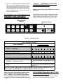
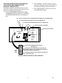
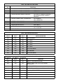
IMI CORNELIUS INC. One Cornelius Place Anoka, MN. 55303–6234 Telephone (612) 421–6120 Facsimile (612) 422–3232 ADDENDUM TO SERVICE MANUALS (IMI CORNELIUS INC; P/N 324229000, 326093000, AND 326142000) FOR FCB (FROZEN CARBONATED BEVERAGE) POST-MIX DISPENSERS The purpose of this addendum is to provide programming instructions for the new V3 electronics now used in the FCB Post–Mix Dispensers. The V3 electronics has new features and operations. The new features include a real-time clock that allows programming of ‘‘DEFROST’’, ‘‘SLEEP’’ (SLEEP TIME) and ‘‘WAKE UP’’ (WAKE UP TIME) when you wish these functions to operate. A new viscosity system program has simplified viscosity set–up by selecting the viscosity from a range of 4 (wet) to 12 (stiff). The Unit will now automatically calibrate the beater motors (viscosity sensing) to provide a long term viscosity consistency. The components ‘‘DIAGNOSTIC’’ (DIAGNOSTIC MODE) functions and other set–up functions are now easily displayed on the message display. A ‘‘TOTALS’’ (DISPLAYED CYCLES AND HOURS TOTALS) menu has been added to the new V3 electronics. Purpose of the ‘‘TOTALS’’ menu is to display total operation hours and cycles readouts on the message display. Disregard all programming instructions documented in service manual provided with your dispenser. All remaining information in your service manual and programming instructions in this addendum are to be used. Retain this addendum as part of your service manual. Below is a list of the FCB Post– Mix Dispensers model numbers contained in each manual. SERVICE MANUALS DISPENSER MODEL NO. 324229000 416116068 326093000 416100073 416100068 496100068 326142–000 416120068 416120073 496120068 BEATER MOTOR SELECT IMPORTANT: Before connecting electrical power to Unit, refer to Unit nameplate and note if Unit is to be operated with 50 or 60HZ electrical power and also note beater motor manufacturer’s name. 1. Remove two screws securing Unit top cover, then remove cover. 2. Remove four screws securing Unit upper control box cover, then remove cover for access to the master circuit board. (see Figure 2). 3. After noting if Unit is to be operated with 50 or 60HZ electrical power and beater motors manufacturer’s name, refer to Figure 2 and Table 3. to place DIP switch assembly No. 6, No. 7 and No. 8 switches in appropriate positions. IMI Cornelius Inc; 1991 ADJUSTING BEATER MOTOR CURRENT (EITHER SIDE) IMPORTANT: Adjustment of Beater Motors Currents should be performed with both freeze cylinders thoroughly defrosted (partially defrosted freeze cylinders may cause false current readings on message display). NOTE: Make sure No. 5 ‘‘MOTOR CURRENT SELF CALIBRATION’’ switch on DIP SWITCH assembly on master circuit board (see Figure 2) is in ‘‘OFF’’ position. No. 5 switch in ‘‘OFF’’ position allows the ‘‘MOTOR CURRENT SELF CALIBRATION’’ electronics to automatically self–calibrate the beaters motors currents at completion of each defrost cycle. Adjust BEATER MOTOR CURRENT (EITHER SIDE) as follows: 1. Place No. 4 ‘‘BEATER MOTOR CURRENT READOUT’’ on DIP SWITCH assembly on master circuit board (see Figure 2) in ‘‘ON’’ position. Both freeze cylinders beater motors will start and operate and beaters motors current ratings will be displayed on message display. 2. Display should be adjusted to read A150 B150 ± 2 by adjusting MOTOR CURRENT ADJUSTMENTS located on No. 1 and No. 2 relay circuit boards (see Figure 2). These figures will fluctuate slightly with variations in line voltage and motor loads. Revised November 18, 1991 August 19, 1991 1409 3. Place No. 4 ‘‘BEATER MOTOR CURRENT READOUT’’ switch on DIP SWITCH assembly in ‘‘OFF’’ position to remove beaters motors current readings from message display. After initial beater motors currents adjustments, the electronics will automatically self–calibrate the motors currents at completion of each defrost cycle. ‘‘TOTALS’’ (DISPLAYED CYCLES AND HOURS TOTALS) INTO UNIT NOTE: The Unit control panel switches are as shown in Figure 1. The following instructions outline adjustments and programming main menu selections, components ‘‘DIAGNOSE’’ (DIAGNOSTIC MODE), and ‘‘TOTALS’’ (DISPLAYED CYCLES AND HOURS TOTALS) into Unit. ADJUSTMENTS AND PROGRAMMING MAIN MENU SELECTIONS, COMPONENTS ‘‘DIAGNOSE’’ (DIAGNOSTIC MODE), AND HIDDEN SECURITY SWITCH MESSAGE DISPLAY FIGURE 1. CONTROL PANEL Table 1. Main Menu Selections MESSAGE DISPLAY (EXAMPLE READOUTS) MENU COMMANDS “CLOCK” (TIME OF DAY) C _ 1 2 - 0 0 A “DEFROST” (AUTOMATIC) 3 D 1 0 - 0 0 A “SLEEP” (SLEEP TIME) S 1 2 - 3 0 A _ “WAKE UP” (WAKE UP TIME) W _ 0 7 - 1 5 A “VIS SET” (PRODUCT VISCOSITY SETTING) 1 2 _ _ _ _ 1 0 “VIS READ” (ACTUAL VISCOSITY READOUT) 1 6 _ _ _ _ 1 1 “SENSORS (TEMPERATURES READOUT) 7 5 * 7 5 * 7 5 “VOLTAGE” (DISPLAYED VOLTAGE READOUT) V R M S * 2 3 0 “DIAGNOSE” (DIAGNOSTIC MODE) See Programming Components Diagnose into Unit. “TOTALS” See Table 5 and programmings “TOTALS” (DISPLAYED CYCLES AND HOURS TOTALS) into unit. see note below NOTE: the “CLOCK” (TIME OF DAY) must be programmed into the Unit before “DEFROST” (AUTOMATIC) “SLEEP” (SLEEP TIME), and “WAKE UP” (WAKE UP TIME) will function. NOTE: Plain water, CO2 and syrup supplies to Unit must be satisfied to turn off ‘‘H2O OUT’’, ‘‘CO2 OUT’’, ‘‘SYRUP 1’’, and ‘‘SYRUP 2,’’ fault messages on message display before adjustments and programming procedures can be performed on the Unit. 1409 2 PROGRAMMING MAIN MENU SELECTIONS ONTO MESSAGE DISPLAY The MAIN MENU SELECTIONS (see table 1) May be brought up on the message display as follows: 1. Press ‘‘AUTO 1’’, ‘‘WASH 1,’’ and ‘‘BLEND 1’’control switches (see Figure 1) at the same time and hold them pressed for a minimum of 1/2 second to bring up MAIN MENU SELECTIONS on message display. The word ‘‘CLOCK’’ will appear on display. You are now in the MAIN MENU SELECTIONS as shown in Table 1. To advance through the MENU SELECTIONS, repeatedly press the ‘‘CANCEL DEFROST’’ (ADVANCE) switch. Once you reach the desired selection, Press the ‘‘DEFROST’’ (SELECT) switch to lock in on the selection. NOTE: to exit MENU SELECTION and go back to MAIN MENU SELECTIONS, press ‘‘ERROR RESET’’ (RESET) switch. Press ‘‘ERROR RESET (RESET) switch a second time to exit from MAIN MENU SELECTIONS. 1. Refer to PROGRAMMING MAIN MENU SELECTIONS ON TO MESSAGE DISPLAY and bring up ‘‘DEFROST’’ on message display. Press ‘‘DEFROST’’ (SELECT) switch to lock in on selection. 2. Press ‘‘CANCEL DEFROST’’ (ADVANCE) switch to bring up flashing hour number on display. 3. Press ‘‘CANCEL DEFROST’’ (ADVANCE) switch to advance hours on display to desired hour. Press ‘‘DEFROST’’ (SELECT) switch to lock in hour on display. 4. After hour (time of day) has been locked in on message display, minute numbers will be flashing on display. Press ‘‘CANCEL DEFROST’’ (ADVANCE) switch to advance minute numbers to desired minutes (time of day). Press ‘‘DEFROST’’ (SELECT) switch to lock in minute (time of day) on display. SETTING ‘‘CLOCK’’ (TIME OF DAY) NOTE: The ‘‘CLOCK’’ (TIME OF DAY) must be programmed into Unit before ‘‘DEFROST’’ (AUTOMATIC), ‘‘SLEEP’’ (SLEEP TIME), and ‘‘WAKE UP’’ (WAKE UP TIME) can be programmed into the Unit. Program ‘‘CLOCK’’ (TIME OF DAY) into Unit as follows: 1. Refer to PROGRAMMING MAIN MENU SELECTIONS ONTO MESSAGE DISPLAY and bring up ‘‘CLOCK’’ on display. Press ‘‘DEFROST’’ (SELECT) switch to lock in on selection. 2. Press ‘‘CANCEL DEFROST’’ (ADVANCE) switch to bring up flashing hour number on display. 3. Press ‘‘CANCEL DEFROST’’ (ADVANCE) switch to advance hours on display to desired hour. Press ‘‘DEFROST’’ (SELECT) switch to lock in hour on display. 4. After hour (time of day) has been locked in on message display, minute numbers will be flashing on display. Press ‘‘CANCEL DEFROST’’ (ADVANCE) switch to advance minute numbers to desired minutes (time of day). Press ‘‘DEFROST’’ (SELECT) switch to lock in minute (time of day) on display. 5. Press ‘‘ERROR RESET’’ switch two times to exit from MENU SELECTION. PROGRAMMING ‘‘DEFROST’’ (AUTOMATIC) SETTINGS INTO UNIT. The automatic defrost system may be programmed into the Unit to occur up to nine different times during a day with a minimum of two hours between defrost time settings. Program automatic defrost time settings into the Unit as follows: 3 5. Press ‘‘DEFROST’’ (SELECT) switch, then repeat steps 2, 3, and 4 to program in next defrost time setting. MAKE SURE A MINIMUM OF TWO HOURS IS MAINTAINED BETWEEN DEFROST TIME SETTINGS. IF A TIME SETTING OF LESS THAN TWO HOURS IS PROGRAMMED INTO THE UNIT, A MOMENTARY ‘‘ERROR’’ MESSAGE WILL APPEAR ON THE MESSAGE DISPLAY WHEN OPERATOR TRIES TO EXIT ‘‘DEFROST’’. THE PROGRAM WILL NOT ALLOW THE OPERATOR TO EXIT THE DEFROST SETTING UNTIL THE LESS THAN TWO HOUR DEFROST TIME IS CORRECTED. THE OPERATOR MUST PRESS ‘‘CANCEL DEFROST’’ (ADVANCE) SWITCH, THEN REPEAT STEPS 2, 3, AND 4 TO PROGRAM CORRECTED DEFROST TIME INTO UNIT. 6. Repeat steps 5 as many times as necessary to pro– gram desired number of defrost time settings into the Unit. 7. Press ‘‘ERROR RESET’’ switch two times to exit from MENU SELECTIONS. PROGRAMMING ‘‘SLEEP’’ (SLEEP TIME) INTO UNIT. ‘‘SLEEP’’ (SLEEP TIME) may be programmed into Unit to occur any time of the day after the Unit automatic defrost cycle has occurred. Unit will shut down (go into sleep time) and will not wake up (return to normal operation) until programmed ‘‘WAKE UP’’ (WAKE UP TIME) has occurred. Program ‘‘SLEEP’’ (SLEEP TIME) into Unit as follows: 1. Refer to PROGRAMMING MAIN MENU SELECTIONS ONTO MESSAGE DISPLAY and bring up ‘‘SLEEP’’ on message display. Press ‘‘DEFROST’’ (SELECT) switch to lock in on selection. 2. Press ‘‘CANCEL DEFROST’’ (ADVANCE) switch to bring up flashing hour number on display. 1409 3. Press ‘‘CANCEL DEFROST’’ (ADVANCE) switch to advance hours on display to desired hour. Press ‘‘DEFROST’’ (SELECT) switch to lock in hour on display. 4. After hour (time of day) has been locked in on message display, minute numbers will be flashing on display. Press ‘‘CANCEL DEFROST’’ (ADVANCE) switch to advance minute numbers to desired minutes (time of day). Press ‘‘DEFROST’’ (SELECT) switch to lock in minutes (time of day) on display. 5. Press ‘‘ERROR RESET’’ switch two times to exit from MENU SELECTIONS. Adjusting ‘‘VIS SET’’ (PRODUCT VISCOSITY) determines what product consistency of the dispensed product will be present in each freeze cylinder. Adjust ‘‘VIS SET’’ (PRODUCT VISCOSITY) of the dispensed product as follows: 1. Refer to PROGRAMMING MAIN MENU SELECTIONS ONTO MESSAGE DISPLAY and bring up ‘‘VIS SET’’ on message display. 2. Press ‘‘DEFROST’’ (SELECT) switch to bring up numbers on message display. PROGRAMMING ‘‘WAKE UP’’ (WAKE UP TIME) INTO UNIT ‘‘WAKE UP’’ (WAKE UP TIME) may be programmed into Unit to occur any time of the day to wake Unit up (return to normal operation) after ‘‘sleep time’’ has occurred. Program ‘‘WAKE UP’’ into Unit as follows: 1. Refer to PROGRAMMING MAIN MENU SELECTIONS ONTO MESSAGE DISPLAY and bring up ‘‘WAKE UP’’ on message display. Press ‘‘DEFROST’’ (SELECT) switch to lock in on selection. NOTE: The direction of arrows (Ơơ) on message display indicates which set of numbers belongs to which freeze cylinder. A No. 4 setting indicates the thinnest product consistency of dispensed product and a No. 12 setting indicates the thickest consistency of product dispensed. 3. Press ‘‘CANCEL DEFROST’’ (ADVANCE) switch. The left–side freeze cylinder viscosity number will be flashing on message display. 2. Press ‘‘CANCEL DEFROST’’ (ADVANCE) switch to bring up flashing hour number on display. 3. Press ‘‘CANCEL DEFROST’’ (ADVANCE) switch to advance hours on display to desired hour. Press ‘‘DEFROST’’ (SELECT) switch to lock in hour on display. 4. After hour (time of day) has been locked in on message display, minute numbers will be flashing on display. Press ‘‘CANCEL DEFROST’’ (ADVANCE) switch to advance minute numbers to desired minutes (time of day). Press ‘‘DEFROST’’ (SELECT) switch to lock in minutes (time of day) on display. 4. Press ‘‘CANCEL DEFROST’’ (ADVANCE) switch to advance viscosity number to desired setting. Press ‘‘DEFROST’’ (SELECT) switch to lock in viscosity setting. The right–side freeze cylinder viscosity number will now be flashing. 5. Press ‘‘CANCEL DEFROST’’ (ADVANCE) switch to advance viscosity number to desired setting. Press ‘‘DEFROST’’ (SELECT) switch to lock in viscosity setting. 6. Press ‘‘ERROR RESET’’ switch two times to exit from MENU SELECTIONS. ‘‘VIS READ’’ (ACTUAL VISCOSITY READOUT) OF PRODUCT IN FREEZE CYLINDERS 5. Press ‘‘ERROR RESET’’ switch two times to exit from MENU SELECTIONS. PROGRAMMING POINT OF SALE MESSAGE DISPLAY (see Figure 2 and Table 4) NOTE: Point of sale display messages may be turned off by placing No. 1, No. 2, and No. 3 switches on master circuit board (see Figure 2 and Tables 2 and 4) DIP SWITCH assembly in appropriate positions. Five point of sale display messages are available to choose from and may be programmed by placing No. 1, No. 2, and No. 3 switches on DIP SWITCH assembly on master circuit board in appropriate positions. Refer to Figure 2 and Tables 2 and 4 and program desired point of sale display message which will be displayed on message display. 1409 ADJUSTING ‘‘VIS SET’’ (PRODUCT VISCOSITY) OF DISPENSED PRODUCT 4 ‘‘VIS READ’’ (ACTUAL VISCOSITY READOUT) may be brought up on message display to actually read the viscosity (product consistency) of the product in the freeze cylinders while the Unit is in operation. Bring ‘‘VIS READ’’ up on message display as follows: 1. Refer to PROGRAMMING MENU SELECTIONS ON MESSAGE DISPLAY and bring up ‘‘VIS READ’’ of product in freeze cylinders. 2. Press ‘‘DEFROST’’ (SELECT) switch to bring up actual viscosity readout of product in each freeze cylinder. 3. Press ‘‘ERROR RESET’’ switch two times to exit from MENU SELECTIONS. DISPLAYED EVAPORATOR REFRIGERATION COILS INLETS AND COMMON OUTLET SENSORS TEMPERATURES. 2. Press ‘‘DEFROST’’ (SELECT) switch to bring up evaporator refrigeration coils inlet and common outlet temperature readings in degrees Fahrenheit. Evaporator refrigeration coils inlet and common outlet temperature readings in degrees Fahrenheit may be displayed on message displays as follows: 3. Press ‘‘ERROR RESET’’ switch two times to exit from MENU SELECTIONS. 1. Refer to PROGRAMMING MENU SELECTIONS ON MESSAGE DISPLAY and bring up ‘‘SENSORS’’ (TEMPERATURES READOUT) on message display. NO. 1 AND NO. 2 EVAPORATOR COILS REFRIGERATION COMMON OUTLET TEMPERATURES NO. 2 EVAPORATOR REFRIGERATION COIL INLET TEMPERATURE NO. 1 EVAPORATOR REFRIGERATION COIL INLET TEMPERATURE MOTOR CURRENT ADJUSTMENT RELAY CIRCUIT BOARD NO. 1 MASTER CIRCUIT BOARD MASTER CIRCUIT BOARD RELAY CIRCUIT BOARD NO. 2 1 2 3 4 5 6 7 8 9 10 DIP SWITCH ASS’Y } } POINT OF SALE MESSAGE DISPLAY SELECT (SEE TABLE 4) BEATER MOTORS CURRENT READOUT (SEE TABLE 2) MOTOR CURRENT SELF CALIBRATION (SEE TABLE 2) BEATER MOTOR SELECT (SEE TABLE 3) APPLICABLE ELECTRIC OR GAS DEFROST (SEE TABLE 2) SERVICE USE ONLY FIGURE 2. MASTER AND RELAY CIRCUIT BOARDS 5 1409 Table 2. DIP SWITCH FUNCTIONS SWITCH NO. FUNCTION 1 POINT OF SALE MESSAGE SELECT SEE TABLE 4 2 POINT OF SALE MESSAGE SELECT SEE TABLE 4 3 POINT OF SALE MESSAGE SELECT SEE TABLE 4 4 BEATER MOTOR CURRENT READOUT ON- DISPLAY CURRENT READOUT OFF- NO DISPLAYED CURRENT READOUT 5 MOTOR CURRENT SELF CALIBRATION NO- DISABLED OFF- OPERATING 6 BEATER MOTOR SELECT SEE TABLE 3 7 BEATER MOTOR SELECT SEE TABLE 3 8 BEATER MOTOR SELECT SEE TABLE 3 9 DEFROST NO- HOT GAS OFF- ELECTRIC 10 SERVICE USE Table 3. BEATER MOTOR SELECT DIP SWITCH NO. 6 DIP SWITCH NO. 7 DIP SWITCH NO. 8 OFF OFF OFF 60 HZ KLAUBER OFF ON OFF NOT USED ON OFF OFF NOT USED ON ON OFF NOT USED ON ON ON NOT USED ON OFF ON 50 HZ VON WEISE OFF ON ON 60 HZ BODINE OFF OFF ON 60 HZ VON WEISE DIP SWITCH NO. 1 MOTOR SELECTED Table 4. POINT OF SALE DISPLAY MESSAGES DIP SWITCH DIP SWITCH NO. 2 NO. 3 MESSAGE OFF OFF OFF “ENJOY A FROZEN BEVERAGE” OFF ON OFF “ENJOY THESE FINE COCA COLA BRAND BEVERAGES” ON OFF OFF “HAVE A NICE DAY” ON ON OFF “DISFRUTE UNA BEBIDA CONGELADA CARBONATADA” ON ON ON “ENJOY A PEPSI FREEZE” ON OFF ON NOT USED - BLANK OFF ON ON NOT USED - BLANK OFF OFF ON DISABLES POINT OF SALE -- BLANK 1409 6 ‘‘VOLTAGE’’ (DISPLAYED VOLTAGE READOUT) Displayed voltage readout may be displayed on message display as follows: 1. Refer to PROGRAMMING MENU SELECTIONS ON MESSAGE DISPLAY and bring up ‘‘VOLTAGE’’ (DISPLAYED VOLTAGE READOUT) on message display. 2. Press ‘‘DEFROST’’ (SELECT) switch to bring up voltage readout on message display. 3. Press ‘‘ERROR RESET’’ switch two times to exit from MENU SELECTIONS. PROGRAMMING COMPONENTS ‘‘DIAGNOSE’’ (DIAGNOSTIC MODE) INTO UNIT ‘‘DIAGNOSE’’ (DIAGNOSTIC MODE) may be programmed into the Unit to check certain components for operation. Program ‘‘DIAGNOSE’’ into Unit and check components for proper operation as follows: 1. Refer to PROGRAMMING MAIN MENU SELECTIONS ONTO MESSAGE DISPLAY and bring up the word ‘‘CLOCK’’ on display. 10. Press ‘‘CANCEL DEFROST’’ (ADVANCE) switch to advance and bring up ‘‘SYRUP 1’’ On message display. 11. Press ‘‘DEFROST’’ (SELECT) switch. No. 1 syrup solenoid relay will click when switch is pressed. 12. Press ‘‘CANCEL DEFROST’’ (ADVANCE) switch to advance and bring up ‘‘SYRUP 2’’ on message display. 13. Press ‘‘DEFROST’’ (SELECT) switch. No. 2 syrup solenoid relay will click when switch is pressed. 14. Press ‘‘CANCEL DEFROST’’ (ADVANCE) switch to advance and bring up ‘‘WATER 1’’ on message display. 15. Press ‘‘DEFROST’’ (SELECT) switch. No. 1 carbonated water solenoid relay will click when switch is pressed. 16. Press ‘‘CANCEL DEFROST’’ (ADVANCE) switch to advance and bring up ‘‘WATER 2’’ on message display. 17. Press ‘‘DEFROST’’ (SELECT) switch . No. 2 carbonated water solenoid relay will click when switch is pressed. 2. Press ‘‘CANCEL DEFROST’’ (ADVANCE) switch to advance through MAIN MENU until ‘‘DIAGNOSE’’ menu appears on message display. Press ‘‘DEFROST’’ (SELECT) switch to lock “DIAGNOSE’’ menu in place. The word ‘‘MOTOR 1’’ will appear on message display. 18. Press ‘‘CANCEL DEFROST’’ (ADVANCE) switch to advance and bring up ‘‘RF SOL 1’’ on message display. 3. Press ‘‘DEFROST’’ (SELECT) switch. No. 1 beater motor will start and operate while switch is pressed. 20. Press ‘‘CANCEL DEFROST’’ (ADVANCE) switch to advance and bring up ‘‘RF SOL 2’’ on message display. 19. Press ‘‘DEFROST’’ (SELECT) switch. Refrigeration relay clicks when switch is pressed. 4. Press ‘‘CANCEL DEFROST’’ (ADVANCE) switch to advance and bring up the word ‘‘MOTOR 2’’ on message display. 21. Press ‘‘DEFROST’’ (SELECT) switch. No. 2 refrigeration solenoid clicks when switch is pressed. 5. Press ‘‘DEFROST’’ (SELECT) switch. No. 2 beater motor will start and operate while switch is pressed. 22. Press ‘‘CANCEL DEFROST’’ (ADVANCE) switch to advance and bring up “COMPRESS’’ on message display. 6. Press ‘‘CANCEL DEFROST’’ (ADVANCE) switch to advance and bring up ‘‘DEFROST 1’’ on message display. 23. Press ‘‘DEFROST’’ (SELECT) switch. Compressor and condenser fan motor will start and operate while switch is pressed. 7. Press ‘‘DEFROST’’ (SELECT) switch. No. 1 defrost relay will click when switch is pressed. 24. Press ‘‘CANCEL DEFROST’’ (ADVANCE) switch to advance and bring ‘‘H2O PUMP’’ on message display. 8. Press ‘‘CANCEL DEFROST’’ (ADVANCE) switch to advance and bring up ‘‘DEFROST 2’’ on message display. 25. Press ‘‘DEFROST’’ (SELECT) switch. Carbonator water pump relay on master circuit board clicks when switch is pressed. 9. Press ‘‘DEFROST’’ (SELECT) switch. No. 2 defrost relay will click when switch is pressed. 7 26. Press ‘‘ERROR RESET’’ switch two times to exit from MENU SELECTIONS. 1409 5. Press and hold ‘‘DEFROST’’ (SELECT) switch. Compressor cycles x100 will appear on message display. DISPLAYING ‘‘TOTALS’’ (DISPLAYED CYCLES AND HOURS TOTALS) ONTO MESSAGE DISPLAY (see Tables 1 and 5) ‘‘TOTALS’’ (DISPLAYED CYCLES AND HOURS TOTALS) may be displayed on message display as follows: 1. Refer to PROGRAMMING MAIN MENU SELECTIONS ONTO MESSAGE DISPLAY and bring up the word ‘‘CLOCK’’ on message display. 2. Repeatedly press and release ‘‘CANCEL DEFROST’’ (ADVANCE) switch to advance through main menu until ‘‘TOTALS’’ menu appears on message display. Press ‘‘DEFROST’’ (SELECT) switch to lock ‘‘TOTALS’’ menu in place. The word ‘‘COMP HRS’’ will appear on message display. 6. Use CANCEL DEFROST (ADVANCE) switch to advance through remaining ‘‘TOTALS’’ (DISPLAYED CYCLES AND HOURS TOTAL MENU) see Table 5. Press ‘‘DEFROST’’ (SELECT) switch to obtain message display readings of the individual menu selections. 7. Press ‘‘ERROR RESET’’ switch two times to exit from MENU SELECTIONS. 8. Install Unit upper control box cover and top cover. 3. Press and Hold ‘‘DEFROST’’ (SELECT) switch. Compressor run hours will appear on message display. DISPLAYED ERROR CONDITIONS 4. Press ‘‘CANCEL DEFROST’’ (ADVANCE) switch to advance and bring up ‘‘COMP CYC’’ on message display. Displayed error conditions, associated errors, and items affected by the errors are found in TABLE 6. DISPLAYED ERROR CONDITIONS. 1409 8 Table 5. “TOTALS” (DISPLAYED CYCLES AND HOURS TOTALS) MENU TOTALS MENU COMMANDS DESCRIPTION COMP HRS COMPRESSOR RUN HOURS COMP CYC COMPRESSOR CYCLES X100 DFSTYC1 DEFROST SIDE 1 CYCLES DFSTYC2 DEFROST SIDE 2 CYCLES BLDRCYC1 BLENDER SIDE 1 CYCLES X100 BLDRCYC2 BLENDER SIDE 2 CYCLES X100 SOLDOUT 1 SOLDOUT SYRUP SIDE 1 SOLDOUT 2 SOLDOUT SYRUP SIDE 2 BMTRHRS1 BEATER MOTOR 1 HOURS BMTRHRS2 BEATER MOTOR 2 HOURS PWR ON POWER ON HOURS AUTO ON 1 AUTO SIDE 1 HOURS AUTO ON 2 AUTO SIDE 2 HOURS ERR HRS 1 ERROR SIDE 1 HOURS ERR HRS 2 ERROR SIDE 2 HOURS SLEEP HRS SLEEP MODE HOURS SYR MIN 1 SYRUP MINUTES (SIDE 1) SYR MIN 2 SYRUP MINUTES (SIDE 2) MESSAGE DISPLAY Motor 1 Table 6. DISPLAYED ERROR CONDITIONS ITEMS AFFECTED BY ERROR BEATER BEATER MOTOR 1 MOTOR 2 REFRIG 1 ERROR Low Current, < 109, OFF OFF Sensed on motor one Motor 2 Low Current, < 109, Sensed on motor two Motor 1 High current > 255, Sensed on motor one Motor 2 High current > 255, Sensed on motor two OFF OFF OFF OFF OFF OFF REFRIG 2 OFF OFF REFRIG Maximum Run Time on compressor SYRUP 1 Syrup Out Side One OFF OFF SYRUP 2 Syrup Out Side Two CO2 OUT CO2 Out OFF OFF H2O OUT H2O Out *OFF *OFF SENSOR 1 Temp Sensor Inlet One OFF OFF OFF OFF SENSOR 2 Temp Sensor Inlet Two OFF OFF OFF OFF SENSOR 3 Temp Sensor Outlet OFF OFF OFF OFF OFF OFF *The refrigeration system and carbonator shall continue to operate for 1.5 minutes after a water pressure loss has been detected. If water pressure loss continues beyond 1.5 minutes, the refrigeration system and carbonator will stop. 9 1409 NOTE - Model numbers 416100073, 416100068, and 496100068 contain two circuit board cooling fans. FIGURE 3. WIRING DIAGRAM 1409 10 8. 7. 1. 9. 10. 11. 4. 5. 6. 3. 13. 12. 2. FIGURE 4. DISPENSING VALVE ASSEMBLY Item Part Description Item Part Description 1557 Dispensing Valve Ass’y 7. 325647000 Plate 1. 321653000 O-Ring, .862 by .103 C.S. 8. 317784000 2. 1555 Knob Thread cutting Screw, Phil Truss HD; Stainless Steel, No. 8-32 by 3/8-in. 3. 321651000 Lever, Valve 9. 1576 Housing 325305000 Spring 4. 1556 Body and Shank 10. 5. 321514000 O-Ring, Caged, .562 I.D. by.210 C.S. 11. 1575 Fitting 6. 1554 Valve 12. 1544 Spring 13. 1543 Shaft Release 11 1409 Item 6. 2. 174103000 Tube, .250 I.D. by 1-3/4-in. Long 174103000 Tube, .250 I.D. by 2-1/2-in. Long 8. 174103000 Tube, .250 I.D. by 18-1/2-in. Long 2. 174103000 176001000 Tube, .250 I.D. by 54-in. Long Ferrule, 40 Jaw, for .375 O.D. Tube 3. 176016000 Swivel Nut, 1/2-16 4. 770204 Nipple for .250 I.D. Tube 5. 176305000 Ferrule, 46 Jaw, for .375 O.D. Tube 6. 1561 Connector, Barb 7. 325012000 Shut-off Valve 8. 770601 Fitting, Tee, 1/4-Barb 2. 5. 1. 7. 1. 7. 2. 1. 2. 5. 3. 4. FIGURE 5. PRODUCT TUBE ASSEMBLY 1409 Description Tube Ass’y Product 2. 1. 1. Part 1578 12