1
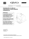
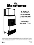
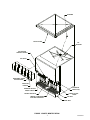
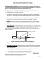
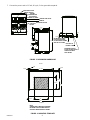
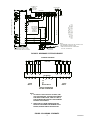
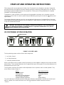
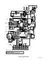
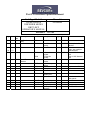
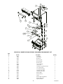
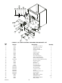
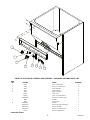
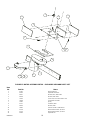
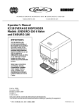
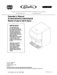
ICE/BEVERAGE DISPENSER
Model DB275--BCP
Operator’s Manual
Part No. 620906904
December, 1997
Revision D
Revised February, 1998
THIS DOCUMENT CONTAINS IMPORTANT INFORMATION
This Manual must be read and understood before installing or operating this equipment
Ó IMI CORNELIUS INC; 1997
PRINTED IN U.S.A
TABLE OF CONTENTS
Page
GENERAL DESCRIPTION . . . . . . . . . . . . . . . . . . . . . . . . . . . . . . . . . . . . . . . . . . . . . . . . . .
2
SAFETY PRECAUTIONS . . . . . . . . . . . . . . . . . . . . . . . . . . . . . . . . . . . . . . . . . . . . . . .
UNIT DESCRIPTION . . . . . . . . . . . . . . . . . . . . . . . . . . . . . . . . . . . . . . . . . . . . . . . . . . .
2
2
SPECIFICATIONS . . . . . . . . . . . . . . . . . . . . . . . . . . . . . . . . . . . . . . . . . . . . . . . . . . . . .
ICEMAKER ADAPTER KITS . . . . . . . . . . . . . . . . . . . . . . . . . . . . . . . . . . . . . . . . . . . .
INSTALLATION INSTRUCTIONS . . . . . . . . . . . . . . . . . . . . . . . . . . . . . . . . . . . . . . . . . . . .
2
2
3
START-UP AND OPERATING INSTRUCTIONS . . . . . . . . . . . . . . . . . . . . . . . . . . . . . . .
6
ICE PORTIONING SYSTEM OPERATION . . . . . . . . . . . . . . . . . . . . . . . . . . . . . . . .
NORMAL OPERATION . . . . . . . . . . . . . . . . . . . . . . . . . . . . . . . . . . . . . . . . . . . . . . . . .
CLEAN MODE . . . . . . . . . . . . . . . . . . . . . . . . . . . . . . . . . . . . . . . . . . . . . . . . . . . . . . . . .
NORMAL ICE PORTION ADJUSTMENT . . . . . . . . . . . . . . . . . . . . . . . . . . . . . . . . . .
6
7
7
7
AGITATION REFILL TIME ADJUSTMENT . . . . . . . . . . . . . . . . . . . . . . . . . . . . . . . .
MANUAL ICE DISPENSING OPERATION . . . . . . . . . . . . . . . . . . . . . . . . . . . . . . . .
EXTRA ICE PORTION ADJUSTMENT . . . . . . . . . . . . . . . . . . . . . . . . . . . . . . . . . . .
CLEANING INSTRUCTIONS . . . . . . . . . . . . . . . . . . . . . . . . . . . . . . . . . . . . . . . . . . . .
DISPENSER . . . . . . . . . . . . . . . . . . . . . . . . . . . . . . . . . . . . . . . . . . . . . . . . . . . . . . . . .
COLD PLATE . . . . . . . . . . . . . . . . . . . . . . . . . . . . . . . . . . . . . . . . . . . . . . . . . . . . . . . . .
7
7
8
8
8
8
BEVERAGE SYSTEM CLEANING AND SANITIZING . . . . . . . . . . . . . . . . . . . . . . .
MAINTENANCE . . . . . . . . . . . . . . . . . . . . . . . . . . . . . . . . . . . . . . . . . . . . . . . . . . . . . . . . . . .
9
10
DAILY (OR AS REQUIRED) . . . . . . . . . . . . . . . . . . . . . . . . . . . . . . . . . . . . . . . . . . . . .
WEEKLY (OR AS REQUIRED) . . . . . . . . . . . . . . . . . . . . . . . . . . . . . . . . . . . . . . . . . .
MONTHLY . . . . . . . . . . . . . . . . . . . . . . . . . . . . . . . . . . . . . . . . . . . . . . . . . . . . . . . . . . . .
TROUBLESHOOTING . . . . . . . . . . . . . . . . . . . . . . . . . . . . . . . . . . . . . . . . . . . . . . . . . . . . . .
10
10
10
12
BLOWN FUSE OR CIRCUIT BREAKER. . . . . . . . . . . . . . . . . . . . . . . . . . . . . . . . . . .
SLUSHY ICE. WATER IN HOPPER . . . . . . . . . . . . . . . . . . . . . . . . . . . . . . . . . . . . . .
12
12
BEVERAGES DO NOT DISPENSE. . . . . . . . . . . . . . . . . . . . . . . . . . . . . . . . . . . . . . .
BEVERAGES TO SWEET. . . . . . . . . . . . . . . . . . . . . . . . . . . . . . . . . . . . . . . . . . . . . . .
BEVERAGES NOT SWEET ENOUGH. . . . . . . . . . . . . . . . . . . . . . . . . . . . . . . . . . . .
BEVERAGES NOT COLD (UNITS WITH BUILD-IN COLD PLATE). . . . . . . . . . .
NO ICE DISPENSED FROM ICE PORTION CONTROLLER . . . . . . . . . . . . . . . .
NO ICE DISPENSED FROM MANUAL ICE DISPENSE
PUSHBUTTON SWITCH . . . . . . . . . . . . . . . . . . . . . . . . . . . . . . . . . . . . . . . . . . . . . . . .
12
12
12
12
13
WARRANTY . . . . . . . . . . . . . . . . . . . . . . . . . . . . . . . . . . . . . . . . . . . . . . . . . . . . . . . . . . . . . .
19
i
13
620906904
TABLE OF CONTENTS (cont’d)
LIST OF FIGURES
Page
FIGURE 1. PARTS IDENTIFICATION . . . . . . . . . . . . . . . . . . . . . . . . . . . . . . . . . . . .
1
FIGURE 2. DRIP-TRAY DRAIN ASSEMBLY FOR BOTTOM HOOK-UP . . . . . . .
FIGURE 3. DISPENSER DIMENSIONS . . . . . . . . . . . . . . . . . . . . . . . . . . . . . . . . . . .
FIGURE 4. MOUNTING TEMPLATE . . . . . . . . . . . . . . . . . . . . . . . . . . . . . . . . . . . . .
FIGURE 5. BEVERAGE SYSTEM SCHEMATIC . . . . . . . . . . . . . . . . . . . . . . . . . . .
FIGURE 6. PLUMBING SCHEMATIC . . . . . . . . . . . . . . . . . . . . . . . . . . . . . . . . . . . . .
FIGURE 7. CUP SIZE LABEL . . . . . . . . . . . . . . . . . . . . . . . . . . . . . . . . . . . . . . . . . . .
FIGURE 8. WIRING DIAGRAM . . . . . . . . . . . . . . . . . . . . . . . . . . . . . . . . . . . . . . . . . .
3
4
4
5
5
6
11
FIGURE 9. ICE/SOFT DRINK POST-MIX DISPENSER EXPLODED VIEW
AND PART LIST . . . . . . . . . . . . . . . . . . . . . . . . . . . . . . . . . . . . . . . . . . . . . . . . . . . . . . .
FIGURE 10. CABINET/ICE BIN ASSEMBLY EXPLODED VIEW
AND PART LIST . . . . . . . . . . . . . . . . . . . . . . . . . . . . . . . . . . . . . . . . . . . . . . . . . . . . . . .
FIGURE 11. ICE CHUTE ASSEMBLY EXPLODED VIEW AND PARTS LIST . . .
FIGURE 12. ELECTRICAL CONTROL BOX ASSEMBLY -- EXPLODED VIEW
AND PARTS LIST . . . . . . . . . . . . . . . . . . . . . . . . . . . . . . . . . . . . . . . . . . . . . . . . . . . . . .
FIGURE 13. MOTOR ASSEMBLY DETAIL -- EXPLODED VIEW
AND PARTS LIST . . . . . . . . . . . . . . . . . . . . . . . . . . . . . . . . . . . . . . . . . . . . . . . . . . . . . .
620906904
ii
14
15
16
17
18
RETAINER
ICE BIN COVER
ICE
AGITATOR
ICE PORTION
CONTROL MODULE
ICE CHUTE
28518
28518
28518
28518
28517
28519
28519
28519
28519
28519
28519
28519
28519
28519
28519
28519
28519
28519
28519
28519
28519
28519
28519
REMOVABLE STRAW
HOLDER PANEL
28519
28518
28518
52189
52189
52189
70924
70924
52189 52189 70924
70924
70924
70924
70924
70924
70924 70924
70924
70924
70924
70924
70924
70924
70924
70924
70924
70924
70924
70924
70924
70924
70924
70924
70924
70924
70924
70924
70924
70924
70924
70924
70924
70924
70924
70924
70924
70924
70924
70924
70924
70924
52189
5218970924
LID/STRAW
HOLDER
BEVERAGE
FAUCETS (8)
70924
MANUAL ICE DISPENSE
PUSH BUTTON SWITCH
52189
52189
52189
52189
52189
MANUAL AIR VALVE
70924
70924
70924
70924
70924
70924
70924
70924
70924
70924
70924
70924
70924
70924
70924
70924
70924
70924
70924
70924
70924
70924
70924
70924
70924
70924
70924
70924
70924
70924
70924
70924
70924
70924
70924
70924
70924
70924
70924
70924
70924
70924
70924
70924
BEVERAGE FAUCET
ON/OFF SWITCH
52189
52189
52189
LOWER ACCESS
PANEL
CUP REST
DRIP TRAY
FIGURE 1. PARTS IDENTIFICATION
1
620906904
GENERAL DESCRIPTION
This section gives the Unit description, theory of operation, and design data for Ice/Beverage Dispenser, Model
number DB275--BCP
IMPORTANT: To the user of this manual -- This manual is a guide for installing, operating, and maintaining this equipment. Refer to the Table of Contents for page location for detailed information pertaining to questions that arise during installation, operation, service, or maintenance of this equipment.
SAFETY PRECAUTIONS
Always: disconnect power to the dispenser before servicing or cleaning.
Never: place hands inside of hopper or gate area without disconnecting power to the dispenser. Agitator
rotation occurs automatically when dispenser is energized!
This ice dispenser has been specifically designed to provide protection against personal injury and eliminates
contamination of ice. To insure continued protection and sanitation, observe the following.
Always: be sure the removable lid is properly installed to prevent unauthorized access to the hopper interior
and possible contamination of the ice.
Always: be sure the upper and lower front panels are securely fastened.
Always: keep area around the dispenser clean of ice cubes.
CAUTION: Dispenser cannot be used with crushed or flaked ice. Use of bagged ice which
has frozen into large chunks can void warranty. The dispenser agitation is not designed to
be an ice crusher. Use of large chunks of ice which “jam up” inside the hopper will cause
failure of the agitator motor and damage to the hopper. If bagged ice is used, it must be carefully
and completely broken into small, cube-sized pieces before filling into the dispenser hopper.
UNIT DESCRIPTION
The Remcor “DB”series of ice dispensers solve your ice and beverage service needs in the sanitary, space
saving, economical way. Designed to be manually filled with ice from any remote ice making source, these dispensers will dispense cubes (up to 1-1/4”in size), cubelets and hard-chipped or cracked ice, and in addition,
several flavors of post-mix beverages.
The unit includes beverage faucets and a cold plate and is designed to be supplied direct from syrup tanks and
carbonator, with no addition cooling required.
SPECIFICATIONS
Model:
Ice Storage:
Maximum Number of Faucets Available
Built-in Cold Plate
Electrical:
Dimensions:
Drain Connection 7/8 ID Hose
DB275S-BCP
275 lbs.
8
Yes
115/1/60
30”W x 30”D x 41½ ”H
ICEMAKER ADAPTER KITS
Remcor model Ice/Beverage Dispensers are designed to be used with one of several different types of topmounted icemakers. The icemaker must be obtained from the appropriate manufacturer.
Check with a Remcor Sales Coordinator for a list of icemaker kits available for this dispenser model. The kit will
contain parts and instructions necessary to mount the selected icemaker to the dispenser.
2
620906904
INSTALLATION INSTRUCTIONS
IMPORTANT: TO THE INSTALLER.
It is the responsibility of the installer to ensure that the water supply to the dispensing equipment is
provided with protection against backflow by an air gap as defined in ANSI/ASME A112. 1.2-1979; or an
approved vacuum breaker or other such method as proved effective by test.
Water pipe connections and fixtures directly connected to a potable water supply shall be sized,
installed, and maintained according to Federal, State, and Local laws.
1. Locate the dispenser indoors on a level counter top.
The ice dispenser must be sealed to the counter. The template drawing (Figure 4) indicates openings
which must be cut in the counter. Locate the desired position for the dispenser, then mark the outline dimensions on the counter using the template drawings. Cut openings in the counter.
Apply a continuous bead of National Sanitation Foundation (NSF) listed silastic sealant (Dow 732 or equal)
approximately 1/4”inside of the unit outline dimensions and around all openings. Then position the unit on
the counter within the outline dimensions. All excess sealant must be wiped away immediately.
2. UTILITIES: The unit has provisions for routing the beverage tubing, air/CO2 line, drain line, and power
cord either out the bottom or out the rear of the cabinet (see Figure 3). For routing the utilities out the bottom of the unit, refer to the mounting template (Figure 4) for locating the required clearance holes in the
counter.
3. DRAIN CONNECTION: Use the insulated tubing and clamp provided with the unit to assemble to the driptray drain. To insure proper drainage, do not allow a “trap”to form in the drain line. Check that the drain line
runs flat with the bottom of the dispenser. See (Figure 2) for bottom hook-up of the unit drain line.
NOTE: This equipment must be installed with adequate backflow protection to comply with Federal,
State, and Local Codes.
DRIP TRAY DRAIN LINE
ELBOW
CLAMP INSULATED
TUBING TO ELBOW
DISPENSER BOTTOM
FIGURE 2. DRIP-TRAY DRAIN ASSEMBLY FOR BOTTOM HOOK-UP
4. BEVERAGE SYSTEM: Connect the beverage system product lines as indicated in the beverage system
schematics shown in Figures 5 & 6. This work should be done by a qualified serviceman.
5. ICE PORTION CONTROLLER: Regulated and filtered CO2 gas pressure or compressed air is required to
operate the ice portion control dispensing system. Proceed as follows to connect the CO2 gas pressure
source line to the dispenser.
A.
Connect and route the Air/CO2 line from outlet side of the source regulator assembly up to the dispenser. NOTE: That the minimum source -- regulated pressure is 40 psig.
B.
Connect the Air/CO2 source line to dispenser inlet line labeled “AIR/CO2”.
C.
The dispenser regulator outlet pressure is factory preset to 34 psig ± 2 psig. DO NOT ADJUST.
IMPORTANT: Maximum Air/CO2 operating pressure is 35 psig.
6. Clean the hopper interior (see cleaning Instructions).
3
620906904
7. Connect the power cord to 115 volt, 60 cycle, 3-wire grounded receptacle.
BEVERAGE VALVE
ON/OFF SWITCH
LID AND
STRAW HOLDER
ICE PORTION
CONTROL (4) SIZES
UF-1 OPTIFILL
VALVES
MANUAL AIR VALVE
MANUAL
DISPENSE SWITCH
35 1/2
31
3 5/8
1 11/16
41 1/2
10 1/8
8
30
8
23
3/8
1 1/8
27 3/4
7 7/16
20 3/4
14 1/2
30
6 1/2
6
REMOVABLE HOLE
PLUGS (2) FOR REAR
HOOKUP OF DRIP
TRAY DRAIN
BACK
1 1/8
14
REMOVABLE PANEL
FOR REAR HOOKUP
OF BEVERAGE TUBING
AND AIR CO2 LINES
ELECTRICAL
POWER CORD
FIGURE 3. DISPENSER DIMENSIONS
17
30
FRONT
NOTE
SHADED AREA INDICATES OPENING
IN CABINET BOTTOM NEEDED FOR
UTILITIES AND BEVERAGE TUBING.
620906904
1 3/16
4 1/2
30
FIGURE 4. MOUNTING TEMPLATE
4
OPTIONAL FOR
DIET OR
ROOT BEER
5--15 PSIG
FAUCETS
1
S1
S2
S3
S4
2
3
REGULATORS
15--50 PSIG
S2
S1
S3
S4
S5
S7
S6
S8
CO2TANK
SYRUP
TANKS
FAUCET NO.
1,5,6,7,8
WATER HOOK
UPS -- MAY BE
CARBONATED
OR PLAIN
WATER AS
REQUIRED
5
6
60--100 PSIG
2
BEVERAGE SYSTEM SCHEMATIC
BC MODELS 19 X 28 COLD PLATE
WITH FRONT INLET FITTINGS
8 VALVE HOOK UP
4
3
NON--CARB. WATER
FAUCETS VIEWED FROM THIS SIDE
4
S5
7
S6
S7
8
S8
COLD PLATE
FILTER
ICE/SOFT DRINK POST MIX
DISPENSER. ITEMS OUTSIDE
BROKEN LINES ARE NOT INCLUDED.
OPTIONAL
PRESSURE
REGULATOR
CARBONATOR
WATER
SUPPLY
NOTES:
1) FOR REFERENCE ONLY NOT FOR CONSTRUCTION.
2) SEE PLUMBING SCHEMATIC LABEL
UNDER LOWER PANEL FOR APPROPRIATE
HOOK UP. (SEE MANUAL)
FIGURE 5. BEVERAGE SYSTEM SCHEMATIC
PLUMBING SCHEMATIC
1
2
3
4
FAUCETS
5
6
7
8
COLDPLATE
1
2
3
4
4
3
2
5
1,5,
6,7,
8
WATER INLETS
SYRUP
INLETS
6
7
8
SYRUP
INLETS
MAY BE CARBONATED
OR NON--CARBONATED
NOTE:
1.
TO SERVICE COLDPLATE INLET FITTINGS, SINK
HAS TO BE REMOVED. TO REMOVE, DISCONNECT
SINK DRAIN CONNECTIONS, THEN LIFT TWO (2)
SIDE MOUNTING PINS AND PULL SINK FORWARD.
REVERSE TO RECONNECT.
2.
MAKE SURE ALL DRAIN CONNECTIONS ARE
PROPERLY POSITIONED FOR DRAINING AFTER
SERVICE, BEFORE PANELS ARE INSTALLED
FIGURE 6. PLUMBING SCHEMATIC
5
620906904
START-UP AND OPERATING INSTRUCTIONS
Fill the hopper with ice and replace the lid. Allow 10 to 15 minutes for the cold plate to cool down. Repeat this
procedure whenever the dispenser has been standing overnight or other long periods without ice use. Start up
the beverage system and adjust faucets to the proper brix. Contact your local syrup distributor for complete
information on the beverage system.
To dispense ice, hold cup under ice chute and press the appropriate size button on the ice portion control located above the ice chute. An extra ice portion may be obtained by pressing the increase key (Y ) before pressing the button.
For beverage dispensing, place a cup on the cup rest against the faucet lever of the desired flavor. Beverage
will be dispensed automatically filling the cup and shutting off. A delay feature is provided in the faucet controller
to “top-off”the drink after shut off.
CAUTION: Use caution to avoid spilling ice when filling dispenser. Clean up immediately
any spilled ice from filling or operating the unit. To prevent contamination of ice, the lid
must be installed at the unit at all times.
ICE PORTIONING SYSTEM OPERATION
INDICATOR LIGHT
DECREASE
SMALL
MEDIUM
LARGE
X-LARGE
INCREASE
FIGURE 7. CUP SIZE LABEL
The ice portioning system consists of three main components:
1. Ice Portion Control
2. Ice Gate Mechanism
3. Solenoid Operated Air Valve
When a size button on the ice portion control is pressed, the control supplies a voltage to the air valve for a brief
period of time. The air cylinder attached to the ice gate will then open the ice gate for a short time allowing ice to
be dispensed from the ice chute.
The ice portion control has five modes to allow adjustment of the ice portions and for normal operation. They
are as follows: (Refer to Figure 7)
INDICATOR STATUS
MODE
Normal operation
Green
Cleaning mode
Red/Amber flashing
Normal ice portion adjustment
Amber
Extra ice portion adjustment
Red
Agitation refill time adjustment
Amber flashing
The control will return to Normal Operation Mode (green indicator) automatically if a button has not been operated for a period of one minute whenever one of the three adjustment modes have been accessed.
6
620906904
NORMAL OPERATION
To dispense ice, hold a cup directly under the ice chute, then press the appropriate size button on the ice portion control. To obtain a full cup of ice, press the increase button followed by the appropriate size button. The ice
portion control will not dispense ice and will display a flashing green indicator light if sufficient ice is not available in the ice chute to dispense the selected size. The indicator light will return to solid green and ice dispensing will resume after the ice chute has been filled.
The amount of ice dispensed for each size is changed in the Normal and Extra Ice Adjustment Modes. To access the adjustment modes, press the decrease and increase button at the same time. The control will advance
to the next mode in the sequence as shown in the table on page 6 and the indicator light will change to identify
which mode is currently active.
CLEAN MODE
Access this mode when cleaning the ice chute. Refer to Cleaning Instructions on pages 7 thru 9.
NORMAL ICE PORTION ADJUSTMENT
From the Normal Operation Mode (green indicator), press both the decrease and increase buttons at the same
time twice. The amber indicator verifies that the normal portion adjustment mode has ben accessed.
To change the amount of ice dispensed, press and hold down the size button for the desired size to be
changed. While holding the size button, press the decrease or increase button to decrease/increase the ice portion size. When the minimum ice portion adjustment has been reached, the indicator will flash at a slow rate; at
the maximum adjustment, the indicator will flash at a fast rate. After releasing the size button, the indicator light
will flash green for five seconds. During this time period a sample can be obtained to check the portion size by
pressing the size key. The indicator light will return to amber (normal portion adjustment mode) after the sample
is dispensed.
The indicator light will flash red after dispensing a sample, if an open circuit exists in the ice gate cylinder switch
wiring to the ice portion control or if an ice gate binding condition occurred during the sample. The indicator light
will display solid red briefly after a sample is dispensed if the ice gate cylinder switch was shorted.
To return to normal operation press the decrease and increase buttons at the same time, press twice.
AGITATION REFILL TIME ADJUSTMENT
To adjust the amount of ice chute refill agitation. begin by accessing the Extra Ice Portion Adjustment Mode
(red Indicator). Next, press and hold for the decrease and increase buttons for three seconds until the indicator
flashes amber. The indicator will flash up to four times, one flash corresponds to the minimum amount of refill
agitation and four flashes corresponds to the maximum amount of refill agitation. Change the amount of refill
agitation by pressing one of the four size buttons -- the small button representing the minimum amount of refill
agitation. Increase the amount of refill agitation if the ice chute does not refill properly after dispensing ice.
To return to Normal Operation Mode, press the decrease and increase buttons at the same time.
MANUAL ICE DISPENSING OPERATION
A pushbutton switch is provided on the upper front panel (see Figure 1) to manualy dispense ice. This system
can be used in the event of a malfunction with the ice portion control or for dispensing ice in portions other than
cup-size. Depress and hold the pushbutton until the desired amount of ice is dispensed.
If a problem with the Air/CO2 ice gate system should occur, a manual air valve is located on the right side of the
upper front panel. The function of this valve is to remove Air/CO2 pressure on the ice gate should a gate
malfunction occur. Move the valve toggle switch to the “manual”position (to the right) and push the gate back to
its open position. Ice can now be dispensed by depressing the manual ice dispense. switch. When the problem
with the Air/CO2 system has been corrected, move the toggle switch left to the “auto”position to restore the unit
to the ice portioning mode of operation.
CAUTION: The gate closes immediately when the toggle switch is moved to the auto
position. Do not place fingers or foreign objects into the ice chute when operating the
toggle switch.
7
620906904
EXTRA ICE PORTION ADJUSTMENT
The adjustment of Extra Ice Portion is accomplished in the same manner as ice portions, except the indicator
light displays red. To access this mode press both the decrease and increase buttons simultaneously three
times for the Normal Operation Mode (green indicator). The indicator will display red.
CLEANING INSTRUCTIONS
DISCONNECT POWER BEFORE CLEANING: Do not use metal scrapers, sharp objects or abrasives on the
ice storage hopper and top cover as damage may result. Do not use solvents or other cleaning agents, as they
may attack the plastic material.
Dispenser
1. Clean the ice storage hopper at lease once a month.
2. Remove, (unscrew) agitator retainer and lift off the agitator. Wash and rinse them thoroughly.
3. Wash down the inside of the hopper and top cover with a mild detergent solution and rinse thoroughly to
remove all traces of detergent.
4. Replace the agitator and agitator retainer.
5. Sanitize the inside of the hopper and agitator with a solution of 1/2 ounce of household bleach in 1 gallon of
water. (200PPM)
6. Clean and sanitize the ice chute as described below:
A.
Enter the Clean Mode of the ice portion control by pressing the decrease and increase button at the
same time. The indicator light will alternately display red/amber.
B.
To empty the ice from the ice chute, press any of the size buttons. The ice gate will then open to allow
the ice chute to empty. The ice gate will automatically close after the ice chute has been emptied.
C.
Remove the 4 thumbscrews attaching the upper service panel and remove the panel.
D.
Remove the 2 thumbscrews attaching the ice chute strap and remove the strap.
E.
Remove the 4 thumbscrews that secure the ice tube to the ice hopper. Remove the ice chute and gate
cover. Power to the ice portion control and beverage valves will be interrupted while the ice chute is
removed.
F.
Wash ice chute, gate slide and gate cover in detergent soap solution. Then rinse thoroughly with plain
water. Sanitize as described in step 5.
G.
Replace components removed for cleaning in reverse order of removal.
H.
Portion control will automatically return to Normal operating mode (green indicator) after the ice chute
is replaced.
COLD PLATE
1. Carefully remove screws holding beverage faucet panel and bring forward.
2. Slide the cold plate cover back. (Remove shipping tape and discard).
3. Remove any debris from the drain trough and spring. Check that drain holes are not clogged.
4. Wash down the inside of the cold plate, tray, and cover with a mild detergent solution and rinse. A small,
long-handled brush will be found helpful in reaching the corners.
5. Slide the cover forward, taking care that it is securely positioned on the cold plate.
8
620906904
6. Replace beverage faucet panel.
BEVERAGE SYSTEM CLEANING AND SANITIZING
1. Prepare the following cleaning, rinsing and sanitizing using a clean, empty figal (5 gallon syrup tank) for
each solution.
CLEANING TANK -- Fill with a solution of 1/2 ounce of a mild liquid detergent (for example, ivory liquid) to
1 gallon of warm (120_) potable water.
RINSING TANK -- Fill with warm (120_F) potable water.
SANITIZING TANK -- Fill with a chlorine sanitizing solution in the strength of 1/2 ounce of household
bleach (sodium hypochlorite) to 1 gallon of cold (ambient) potable water to obtain a solution strength of
200 PPM.
NOTE:
cets.
Repeat the following procedure on each of the unit’s syrup product lines and beverage fau-
2. Using a suitable pail or bucket, fill one with a detergent solution and a second container with a sanitizing
solution is the strengths as described in step 1.
A.
Remove the syrup line quick disconnect fitting from the product tank and submerge in the detergent
solution. Clean with a nylon bristle brush (do not use a wire brush). Rinse with clean potable water.
B.
Wearing sanitary gloves, next submerge the quick disconnect fitting in the sanitizing container for 15
minutes. Remove and air dry.
3. Hook-up the sanitized product line fitting (step 2) to the cleaning tank. Hook-up a gas disconnect fitting to
the tank and pressurize with 60 to 80 psig CO2. Energize the beverage faucet continuously for 1 minute to
remove all air bubbles. Continue to operate the faucet until liquid dispensed is free of any syrup. Cycle the
faucet for 15 seconds on, off and then immediately on again. Repeat this procedure for 15 cycles. Then
energize the faucet to remain flowing for 3 minutes.
4. Hook-up the rinsing tank and pressurize with 60 to 80 psig CO2 . Flush the cleaning solution from the product line by cycling the faucet as described in step 3 and then energize the faucet to flow continuously for 3
minutes.
5. Hook-up the sanitizing tank and pressurize with 60 to 80 psig CO2 . Flow the sanitizing solution through the
beverage faucet by cycling the faucet as described in step 3. Next energize the faucet continuously to flush
at least 2 cups of the sanitizing solution through the system. Finally deenergize the faucet and allow the
sanitizer to remain pressurized in the line for 20 minutes.
6. Wearing sanitary gloves, remove the faucet nozzle and diffuser. Repeat the cleaning and sanitizing procedures as described in step 2, then reassemble to the faucet.
7. Disconnect the sanitizing tank. Hook-up the product tank to the unit and to the CO2 . system. Energize the
faucet to flush the sanitizing solution from the syrup line and the faucet. Continue flow on the faucet until
only syrup is dispensed.
9
620906904
MAINTENANCE
The following dispenser maintenance should be performed at the intervals indicated below.
DAILY (or as required)
Remove foreign material from vending area sink to prevent drain blockage.
WEEKLY (or as required)
Clean vending area. Check for proper water drainage from the vending area sink.
MONTHLY
Clean and sanitize the hopper interior (see cleaning instructions).
620906904
10
WHT
115VAC POWER
L
GROUND
STARTING
RELAY
YEL
N
PRP
3
1
2
4
CAPACITOR
AGITATOR
MOTOR
BLK
BLK
RED
BLK
ICE CHUTE RELAY
BLK
BLUE
BLK
RED
7
A
5
YEL
MAGNETIC ICE
CHUTE SWITCH
WHT
B
W
H
T
N
AGITATOR MOTOR
MERCURY RELAY
B
L
K
BLK
DIODE
BLK
WHT
BLK
YLW
BLK
BEVERAGE
FAUCET TYP. (4)
WHT
YLW/WHT
YLW
YLW/BLK
W
H
T
YLW
Y
L
W
YLW/WHT
BEVERAGE
FAUCET ON/OFF
SWITCH
B
L
K
24V
YLW/BLK
AGITATOR
MOTOR
HEATER
TRANSFORMER
ORG/GRN
WHT
ORG/GRN
ORG/RED
O
R
G
ORG/RED
BLK
BEVERAGE
FAUCET TYP. (4)
YLW
BLK
AGITATION SOLID
STATE RELAY
TRANSFORMER
ORG
2
4
V
WHT
PNEUMATIC GATE
+
WHT/RED
W
H
T
B
L
K
WHT
1
WHT
2
RED
RED
DIODE
+
B
L
K
GRN
RED
RECTIFIER
3
GRN
5
N
C
-B
L
K
BLK
4
N
O
RED
C
C
N
C
B
L
K
RED
WHT
MANUAL DISPENSE
PUSHBUTTON SWITCH
B
L
U
E
--
WHT
N
O
DIODE
TERMINAL
STRIP
RED
100
(2 WATT)
6
G
R
N
2
3
4
5
CYLINDER
MAGNETIC
SWITCH
RED
RED
1
R
E
D
BLK
B
L
K
PNEUMATIC
GATE SOLENOID
W
H
T
RED
Q.C. CONNECTOR
B
L
K
BLK
B
L
U
/
B
R
N
6
7
8
9
ICE PORTION CONTROLLER
SERVICE INFORMATION
DANGER!
ELECTRIC SHOCK HAZARD.
DISCONNECT POWER BEFORE SERVICING UNIT.
FIGURE 8. WIRING DIAGRAM
11
620906904
TROUBLESHOOTING
IMPORTANT: Only qualified personnel should service internal components or electrical wiring.
WARNING: If repairs are to be made to a product system, remove quick disconnects from
the applicable product tank, then relieve the system pressure before proceeding. If repairs
are to be made to the CO2 system, stop dispensing, shut off the CO2 supply, then relieve the
system pressure before proceeding. If repairs are to be made to the refrigeration system, make sure
electrical power is disconnected from the unit.
Trouble
NOTE:
Probable Cause
Remedy
should your unit fail to operate properly, check that there is power to the unit and that the
hopper contains ice. If the unit does not dispense, check the following chart under the
appropriate symptoms(s) to aid in locating the defect.
BLOWN FUSE OR CIRCUIT
BREAKER.
A.
Short circuit in wiring (115V
circuit).
A.
Replace defective wiring.
B.
Defective agitator motor.
B.
Replace agitator motor.
A.
Blocked drain.
A.
Open--up/flush out drain.
B.
Unit not level.
B.
Level unit.
C.
Poor ice quality due to water
quality or ice maker problems.
C.
Install water filter system. For
Icemaker problems, consult
icemaker manual.
D.
Improper use of flaked ice.
D.
Replaced flaked ice with “cube
style ice (see page2, Unit
Description).
A.
No 24 volt power to faucets.
A.
Check that beverage switch is
“on”. Check 24V transformers.
B.
No CO2 pressure.
B.
Check CO2 regulator. Check CO2
tank pressure.
A.
Carbonator not working.
A.
Check carbonator.
B.
No CO2 pressure in
carbonator.
B.
Check CO2 regulator. Check CO2
tank pressure.
C.
Faucet brix requires adjusting.
C.
Brix Faucet.
BEVERAGES NOT SWEET
ENOUGH.
A.
Empty syrup tank.
A.
Refill syrup tank.
B.
Faucet Brix requires adjusting.
B.
Brix Faucet.
BEVERAGES NOT COLD
(UNITS WITH BUILD-IN COLD
PLATE).
A.
Unit standing with no ice in
hopper - no ice in cold plate
cabinet.
A.
Refill hopper with ice.
SLUSHY ICE. WATER IN
HOPPER
BEVERAGES DO NOT
DISPENSE.
BEVERAGES TOO SWEET.
NOTE: Contact your local syrup or beverage equipment distributor for additional information and
trouble shooting of beverage system.
620906904
12
Trouble
NO ICE DISPENSED FROM
ICE PORTION CONTROLLER
NO ICE DISPENSED FROM
MANUAL ICE DISPENSE
PUSHBUTTON SWITCH
ICE DISPENSING DURING
AUTOMATIC AGITATION
Probable Cause
Remedy
A.
Insufficient ice supply in ice
bin.
A.
Replenish ice supply as
instructed.
B.
Ice in ice bin bridged (stuck
together).
B.
Gently tap on ice to break it loose.
C.
No electrical power to
dispenser.
C.
Plug in dispenser power cord, or
check fuse or circuit breaker.
D.
Insufficient or no Air/CO2
supply to dispenser.
D.
Restore CO2 supply to dispenser.
E.
Inoperative ice agitator motor.
E.
Replace ice agitator motor.
F.
Inoperative gate cylinder.
F.
Replace gate cylinder.
G.
Inoperative gate solenoid.
G.
Replace gate solenoid.
H.
Inoperative ice portion
controller.
H.
Replace ice portion controller.
I.
Defective motor capacitor.
I.
Replace capacitor.
J.
Ice gate not aligned to ice
chute.
J.
Check alignment of ice gate to
slot in ice chute.
K.
Agitate relay wiring incorrect.
K.
Red wire should be connected to
“+”terminal of relay coil.
A.
24VAC transformer defective.
A.
Replace transformer.
B.
Defective rectifier.
B.
Replace rectifier.
C.
Incorrect wiring or loose
terminal / defective wire.
C.
Check wiring.
D.
Ice gate not aligned to ice
chute.
D.
Check alignment of ice gate to
slot in ice chute.
E.
Defective air cylinder.
E.
Replace air cylinder
A.
Manual air valve toggle switch
in “manual”position.
A.
Move toggle switch to “auto”
position.
B.
No air/CO2 supply to
dispenser.
B.
Restore air/CO2 pressure to unit.
C.
Defective manual ice dispense
pushbutton switch.
C.
Replace switch.
13
620906904
Part # Corrections/Update Document
Unit Type/Model #
ICE/BEVERAGE
DISPENSER MODEL
DB275-BCP
OPERATOR’S MANUAL
Revision 2
Page Item Old
Part
14
2 52154
14
6
n/a
15
4
32939
18
16
13
20
6/27/06
Description
New Part
Description
Ice Bin Cover,
Gray
52154-1
Bin Lid Kit
JLS
01/27/03
629081401
Touch Panel
Overlay
Motor Kit
JLS
JLS
01/27/03 Overlay for Ice Portion
Module
01/27/03 Includes motor, motor
relay, start capacitor
and hardware
6/27/06 Has a .250” diameter
rod
Has a .188” diameter
rod
01/27/03
JLS
01/27/03 Key is marked D001
Motor
08049
620701201
70888
28378
Manual #
620906904
18
4
Motor Plate
Bracket
28378R
n/a
n/a
32977
n/a
n/a
n/a
n/a
n/a
n/a
n/a
n/a
70739
30995
28708
29328
n/a
n/a
08052
n/a
n/a
n/a
n/a
n/a
n/a
n/a
n/a
33160R
33162
70478R
28004
Ice Gate Air
Cylinder
Ice Gate Air
Cylinder
Motor Plate
Bracket
Keylock Assy
W/Keys
Key
Power Cord
Lid & Straw Holder
“Z” Style Lower
Splash Panel
Splash Guard Kit
Start Capacitor
Motor Start Relay
Push On Clips
Drip Tray
Extension
Agent Date
JLS
SRV
Notes
29.43x10.468
JLS
01/27/03 Includes two clear
side guards
JLS
JLS
01/27/03 For drip tray
01/27/03 30x7 stainless steel
2
26
17
25
22
24
4
27
23
15
16
9
6
8
14
7
13
19
3
21
15
1
5
15
15
20
18
12
10
11
FIGURE 9. ICE/SOFT DRINK POST-MIX DISPENSER EXPLODED VIEW AND PARTS LIST
Index
No.
1
2
3
4
5
6
7
8
9
10
11
12
13
14
15
16
17
18
19
20
21
22
23
24
25*
26*
27*
NOTE:
620906904
Part No.
620504201
52154
28708
28617
52201
32839
70986
70188
70055
620025701
52216
10145
51455
70075
70171
27906R
620025704
52837
51740
70339
52842
31934
620305408
620701203
70833
51955
70299
*Not Shown
Description
Gasket, Cold Plate Drain
Ice Bin Cover, Gray
Cup Lid Holder
Service Panel
Insulation, Cold Plate Drain
Module Ice Portion Control
Cup Rest
Thumbscrew, Service Panel
Nut Clip
Splash Panel
Drip Tray
Mounting Pin, Drip Tray
Rear, Panel
Nut
Screw, Phil Truss Hd, No. 8-32 By 3/8-In. Long
Extension, Controller Mounting
Panel, Upper Front
Tube, Cold Plate Drain
Drain Assembly
Hose Clamp
Hose Clamp
Beverage Faucet On/Off Switch
Manual Ice Dispense Push Button Switch
Manual Air Valve Toggl Switch
Fitting, Air Valve I/8 Barb x 1/8 MPT.
Air line tubing 1/8 ID x 1/16 WALL
Screw, Slotted Truss Hd, No. 6-32
14
Quantity
2
1
1
1
2
1
1
4
2
1
1
2
1
5
8
1
1
2
1
2
1
1
1
1
2
18”
2
19
1
28081
11
10
3
13
18
17
12
5
8
6
15 16
30493
2
4
14
7
9
FIGURE 10. CABINET/ICE BIN ASSEMBLY EXPLODED VIEW AND PART LIST
Index
No.
Part No.
1
28075
Ice Agitator
1
2
70928
Drain Spring
1
3
51101
Motor Seal
1
4
32939
Motor, 120 VAC
1
5
52777
Motor Insulation
1
6
28117
Motor Support
1
7
52162
Cover, Cold Plate
1
8
30439
Junction Box
1
9
32682
Transformer Assembly (24 VAC)
2
Description
Quantity
10
28081
Cover, Electric Box
1
11
70215
Screw, #8 Self-Tapping
2
12
52778
Insulation, Motor Plate
1
13*
52779
Insulation, Motor Plate
1
14
28210
Bracket, Motor
1
15
30794
Heater, 120 VAC
1
16
70341
Spring
2
17
28377
Bracket, Motor Plate (Black)
1
18
28378
Bracket, Motor Plate
1
19
15087
Agitator, Retainer
1
15
620906904
28
23
26
25
19
28
24
11
12
13
27
16 15
10
9
14
9
17
22
21
6
8
2
20
5
18
1
7
3
4
FIGURE 11. ICE CHUTE ASSEMBLY EXPLODED VIEW AND PARTS LIST
Item
No.
Part No.
1
2
3
4
5
6
7
8
9
10
11
12
13
14
15
16
17
18
19
20
21
22
23
24
25
26
27
28*
70906
70173
28417
70170
52139
52179
52236
31981
70122
32953
70828
620025615
70017
51856
70016
70056
52816
620025601
620701204
620701201
620025607
620701202
620701205
620701207
70663
50299
70833
50822
620906904
Description
Screw, #8-32 x 1/2 Nylock
Thumbscrews, Ice Chute
Retainer, Ice Chute
Thumbscrew, #8-32 x 1/2
Ice Chute
Gasket, Ice Chute
Cover, Ice Gate
Activator Magnet
Screw, #4 x 3/8 Type A
Switch, Ice Chute Interlock
Air Valve Solenoid Assembly
Bracket Air Valve Regulator Mounting
Nut, #10-32 Locking
Gasket, Conduit
Nut, #10-32
Washer, Flat, #10
Ice Conduit Assembly
Ice Gate Assembly
Air/CO2 Regulator
Ice Gate Air Cylinder
Ice Gate
Hex Jam Nut 1/4-28 Stn. Stl.
Pressure Gauge
Fitting, 1/8 NPT
Fitting 1/4 Barb x 1/8 MPT
Tubing Air/CO2 Line
Fitting, 1/8 Barb x 1/8 MPT
Plastic Cable Tie
16
Quantity
2
4
1
2
1
1
1
1
4
1
1
1
3
1
4
4
1
1
1
1
1
1
1
1
1
36 In.
2
2
1
2
3
4
5
6
7
8
FIGURE 12. ELECTRICAL CONTROL BOX ASSEMBLY -- EXPLODED VIEW AND PARTS LIST
Item
No.
Part No
1
31375
Relay, Agitator Motor
1
2
31206
Relay, Ice chute Interlock
1
3
32714
Diode Assembly
1
4
31107
Terminal Board
1
5
Name
Quantity
32503
Relay, Solid State
1
30995*
Power Cord
1
32956*
Cable, Ice Chute Interlock
1
Harness, Ice Portion Control
1
620305405*
6
32958
Rectifier
1
7
32244
Terminal Strip
1
8
620305406
Resistor
1
620305401*
Harness, Manual Ice Dispense
1
620305403*
Harness, Rectifier
1
620305402*
Harness, Pneumatic Gate
1
Harness, Agitator Motor
1
31237*
* Items Not Shown
17
620906904
1
11
12
3
4
5
8
5
6
13
9
7
10
6
5
2
FIGURE 13. MOTOR ASSEMBLY DETAIL -- EXPLODED VIEW AND PARTS LIST
Item
No.
Part No.
1
51101
Motor Shaft Seal
2
30794
Agitator Motor Heater
3
28377
Bracket, Back, Motor Plate
4
28378
Bracket, Motor Plate
Name
5
70250
1/4-20 x 1/2 Truss Hd Phl MS Screw
6
70048
1/4 Int tooth Lw Plated
7
70341
Spring
8
52777
Insulation, Motor
9
28210
Bracket, Motor
10
70061
5/16 ID x 3/4 OD x 1/16 Washer
11
52778
Motor Plate Insulation, 3/8 Thick
12
52779
Motor Plate Insulation, 3/4 Thick
13
32939
Agitator Motor
620906904
18
WARRANTY
IMI Cornelius Inc. warrants that all equipment and parts are free from defects in material and workmanship under normal use and service. For a copy of the warranty applicable to your Cornelius, Remcor or Wilshire product, in your country, please write, fax or telephone the IMI Cornelius office nearest you. Please provide the
equipment model number, serial number and the date of purchase.
IMI Cornelius Offices
AUSTRALIA D P.O. 210, D RIVERWOOD, D NSW 2210, AUSTRALIA D (61) 2 533 3122 D FAX (61) 2 534 2166
AUSTRIA D AM LANGEN FELDE 32 D A-1222 D VIENNA, AUSTRIA D (43) 1 233 520 D FAX (43) 1-2335-2930
BELGIUM D BOSKAPELLEI 122 D B-2930 BRAASCHAAT, BELGIUM D (32) 3 664 0552 D FAX (32) 3 665 2307
BRAZIL D RUA ITAOCARA 97 D TOMAS COELHO D RIO DE JANEIRO, BRAZIL D (55) 21 591 7150 D FAX (55) 21 593 1829
ENGLAND D TYTHING ROAD ALCESTER D WARWICKSHIRE, B49 6 EU, ENGLAND D (44) 789 763 101 D FAX (44) 789 763 644
FRANCE D 71 ROUTE DE ST. DENIS D F-95170 DEUIL LA BARRE D PARIS, FRANCE D (33) 1 34 28 6200 D FAX (33) 1 34 28 6201
GERMANY D CARL LEVERKUS STRASSE 15 D D-4018 LANGENFELD, GERMANY D (49) 2173 7930 D FAX (49) 2173 77 438
GREECE D 488 MESSOGION AVENUE D AGIA PARASKEVI D 153 42 D ATHENS, GREECE D (30) 1 600 1073 D FAX (30) 1 601 2491
HONG KONG D 1104 TAIKOTSUI CENTRE D 11-15 KOK CHEUNG ST D TAIKOKTSUE, HONG KONG D (852) 789 9882 D FAX (852) 391 6222
ITALY D VIA PELLIZZARI 11 D 1-20059 D VIMARCATE, ITALY D (39) 39 608 0817 D FAX (39) 39 608 0814
NEW ZEALAND D 20 LANSFORD CRES. D P.O. BOX 19-044 AVONDALE D AUCKLAND 7, NEW ZEALAND D (64) 9 8200 357 D FAX (64) 9 8200 361
SINGAPORE D 16 TUAS STREET D SINGAPORE 2263 D (65) 862 5542 D FAX (65) 862 5604
SPAIN D POLIGONO INDUSTRAIL D RIERA DEL FONOLLAR D E-08830 SANT BOI DE LLOBREGAT D BARCELONA, SPAIN D (34) 3 640 2839 D FAX (34) 3 654 3379
USA D ONE CORNELIUS PLACE D ANOKA, MINNESOTA D (612) 421-6120 D FAX (612) 422-3255
LD004
4/21/98
19
620906904
CORPORATE HEADQUARTERS:
Remcor Incorporated
500 Regency Drive
Glendale Heights, IL 60139
630--539--6850


![Service Manual VA13 Carbonator [ 002818 ]](http://vs1.manualzilla.com/store/data/006013608_1-0f8f87056a0ab013b1dd01dac3912d47-150x150.png)