1
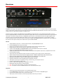
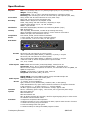
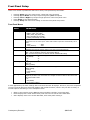
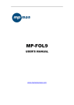
Product Manual QMOD-HD QMOD™ HDTV Modulator July 17, 2014 Control Firmware Ver 5.7 Encoder Firmware 02E7 Contemporary Research 1 QMOD-HD Table of Contents Overview ............................................................................................................................................. 3 Features ................................................................................................................................................... 3 Specifications ...................................................................................................................................... 4 Front Panel Setup ............................................................................................................................... 5 Front Panel Menus .................................................................................................................................... 5 Tips & Troubleshooting ....................................................................................................................... 7 Common Symptoms and Solutions ............................................................................................................. 7 Inserting a QMOD channel that emulates a Cable Guide Channel ................................................................. 8 RS-232 Control Protocol ................................................................................................................... 10 RS-232 Commands ........................................................................................................................... 11 Control Commands ..................................................................................................................................11 Terminal Communication Commands ........................................................................................................11 RS-232 Cable Connections ................................................................................................................ 12 Single QMOD-HD .....................................................................................................................................12 QMOD-HD Daisy-Chain ............................................................................................................................12 Rack Mounting .................................................................................................................................. 13 RK2 Dual Rack Kit with Tie Bar Mounting ..................................................................................................13 RK1 Single Unit Rack Mount .....................................................................................................................13 RK2 – Locking Cases together ..................................................................................................................13 Limited Warranty and Disclaimer ..................................................................................................... 15 Contemporary Research 2 QMOD-HD Overview CR QMOD™ technology is opening the door to new HDTV applications. Create your own on-site HDTV broadband distribution system using a variety HD, SD, and AV sources with the Contemporary Research QMOD-HD HDTV Modulator. No matrix routers or IP resources required, just tune in with standard displays or CR HDTV tuners. Compact and easy to integrate, the QMOD-HD accepts HD RGBHV or Component video, or SD S-Video/Composite NTSC, as well as stereo and digital PCM audio, converts the audio and video to a digital cable channel, and amplifies for distribution through broadband cable system. Innovative in design and value, the QMOD-HD opens the door to cost-effective distribution of digital signage and HD subscriber sources using existing broadband coax cabling in sports, retail and entertainment facilities, corporate offices, colleges, schools and worship centers. Front-panel buttons and text menu display simplify QMOD-HD setup, with options for 2-way integration with custom control systems. GPI inputs can switch to AV inputs for EAS broadcasts. Features Accepts RGBHV, Component, or S-Video/Composite NTSC, 720p/1080i/480/480i formats Presents 480p/480i video as full-screen image Employs pro-grade HD encoding that minimizes artifacts for motion video and signage “tickers” Merges audio with video from analog stereo, digital optical and coax inputs Creates an HD 720p/1080i or SD 480p/480i MPEG-2 stream with MPEG1 stereo audio for broadcast Delivers a fully agile QAM 64/256 digital cable channel 2-135 Amplifies for distribution over an on-site broadband cable system with adjustable output level, compatible with all cable format broadband systems Sets up with front-panel buttons and easy to use menus, including inputs, encoding, channel, and RF options Allows creation of two-part (XX-XX) and single-part (XXX –emulates Guide channel ID) virtual channels Allows use of locking BNC-HD15 or HD15-HD15 cables to connect YPbPr video via the RGB input Responds to GPI inputs to switch to EAS composite video and audio Integrates with RS-232 control and feedback with simple ASCII commands Saves power and rack space using efficient design, fan-free cooling, and compact enclosure Includes compact switching power supply Mounts in optional 1RU single (RK1) or dual (RK2) 19” rack kits Meets RoHS safety and California energy standards New – Auto-sync for input resolution, no need to set output resolution New – Free option to drive 2-4 QMOD Modulators from a 12 VDC 4A power supply. Integration Connect one source to VGA, Component, or S-Video/Composite inputs Use the QMOD-HDSC for VGA sources – computers do not output video-standard 720p/1080i signals Connect audio to digital optical, coax, or stereo audio inputs Select inputs, channel, resolution, and RF output parameters from front-panel menus Contemporary Research 3 QMOD-HD Specifications Physical Front Panel Encoding Modulation Latency Compliance Power Real Panel Size: 8.5” [216mm] wide x 1.75” [44mm] height (1RU) x 6.0” [153mm] deep Weight: 1.5 lbs [0.68kg] Temperature: +32° to 122° F operating temperature, convection cooled Mounting: Rack mounting for one or two units side-by-side optional (RK1, RK2) Setup, Select and directional buttons for front-panel setup Menu LCD, 2 lines of 20 blue characters each MPEG2 Profile: MP@HL for HD, MP@ML for SD 1080i, 720p, 480p, and 480i resolution, depending on input Video Encoding bitrate 13, 15, 18, and 25 Mbps MPEG1, Layer 2 audio Switchable 64/256 QAM, J83 Annex B, Interleaving Modes (128,1) MER 38 dB typical 360 ms@720p, 660ms1080i, includes all processing and tuning HDTV modulators experience more latency, as the media is converted to MPEG2 and QAM, then distributed over RF. FCC Class B, ROHS, meets California standards 2.1mm coaxial jack (inside center conductor positive) 0.7 A maximum, 11.5 to 13.5 VDC, 12 VDC typical R Aud L Video Pwr In 12 VDC RS-232 Control Coax Opti cal SPDIF RGB Pr 0.7A max (_) RS-232 GPI Video Inputs Audio Inputs RF Out Includes Options Firmware (+) Y Made in USA RF Out Pb A/V Inputs DB-9 male, RS-232 data link to control system 300 to 19,200 baud (9600 default), 8 data bits, no parity, 1 stop bit DB-9 male, RS-232 data link to control system 300 to 19,200 baud (9600 default), 8 data bits, no parity, 1 stop bit 3 GPI Pins in DB-9, selects composite/stereo inputs for EAS 4=1, 9=2, 5=GND RGB: RGBHV DB-15 female (1080i/720p/480p), 59.94/29.97 Hz Component: RCA Y, Pb, Pr (1080i/720p/480p/480i) , 59.94/29.97 Hz Note: If source outputs Component on a DB-15, use VGA cable to wire to QMOD, set QMOD to Component S-Video: Y(Composite), C (Blue Pb) 480i, 29.97 Hz Composite: RCA female (480i), 29.97 Hz Digital SPDIF: Coax and TOSlink optical output, PCM 48K sample rate Analog L and R: 2 stereo RCA female jacks Inputs assignable to video inputs ‘F’, female, 75 ohm impedance Agile, channels 2-135 (48-860 MHz), standard, HRC, or IRC spacing 6 MHz bandwidth fits any open channel without interference to adjacent channels 1 KHz resolution, +/- 30 ppm accuracy, +/- 35 ppm stability 29 dBmV typical output power, attenuated in 5 steps, approx 4 dB PS12-1.5 Switching power supply, 1.5A 12 VDC, fits in typical AC power strips RK1 Single Rack Kit RK2 Dual Rack Kit RK2-EZ Dual Rack Kit RK1-AC Single Rack Kit with accessory shelf for digital signage player or video scaler CC-COM RS-232 Null Modem Cable 4.5 Improved composite video operation 4.6 allows selection of 4:3 or 16x9 format on 480i, requires 02E7 encoder firmware 4.7 adds auto-sensing of input resolution 5.4 removes background color glitch 5.7 adds the ability to change the MPEG program number Contemporary Research 4 QMOD-HD Front Panel Setup There are a number of parameters that can be set by front-panel Setup commands. Pressing Setup enters the setup menus, shows last menu accessed Pressing Up and Down arrow keys steps through the QMOD-HD options Pressing Left and Right keys steps through options for each front-panel menu Press Select to save desired option Pressing Setup ends menu item editing or exits the front-panel setup mode Front Panel Menus Menu Parameters Basic Settings Video Input In most cases, the menus below will work for most displays at sites. This selects the appropriate input: - RGBHV (1080i, 720p, 480p) - YPbPr (1080i, 720p, 480p, 480i) - Video (automatic ally uses 480i) - S-Video (automatically uses 480i) The QMOD-HD will now auto-sync to the source resolution. Selections are locked unless there is no active input. Video and S-Video inputs are automatically set to 480i. - 1080i - 480p - 720p (default) - 480i XXX Left/Right steps through channel numbers (use Left to access high channels) Standard cable frequencies (default) HRC – same as Standard, channels 5 and 6 slightly different IRC – All channel frequencies are different than the standard cable setting Sets the output level of the RF output, in dBmV - 29 (default) -17 - 25 -13 - 21 -9 Digi (Digital) Optical Digi Coax Analog (default) Displays a color background with there is no video input, or the resolution doesn’t match the QMOD settings. - Orange - Purple (default) - Green Today, most displays are set to tune 256 QAM. If a site has some very old displays, they might only be able to tune in channels set to 64 QAM. Continuous Wave is often used to test the channel with a meter. - 64 - 256 (default) - CW (Continuous Wave) Video Format Channel Cable Format RF Level dB Audio Input No Vid Color QAM Type In most applications, the basic settings above will work fine with all displays. Of course, there are exceptions to every rule that often arise with older displays with archaic firmware, which is why we offer a variety of encoder options and settings. A few examples include: Older LG sets need to see the MPEG stream encoded at 18 mbps (19.4 mbps total). Newer displays don’t need channel data; older sets need to see the CVCT data table. Some displays want to see certain PMT data, while most prefer setting 0. Contemporary Research 5 QMOD-HD Menu Parameters Quality Settings Trig Lev These adjust the overall quality of encoding This is a cable compensation setting that adjusts output for different Component or RGBHV cables. To see the difference in quality you’ll need a test chart from a Sencore or other HDTV signal generator. Adjust using the same cable you’ll use for the installation. The settings are 1-4, with 2 as the default. This adjusts the quality of the encoded video, in mbits per second. For typical HD satellite/cable, 18 the best solution, as the receiver’s video output rarely exceeds 12 mbps, and old and new display tuners will tune that in. For very good HD video sources, such as from HDTV studio feeds on SDI or Component, 25 may produce visible improvement. Note that some older display tuners don’t expect to see a video stream larger than 19.4, and you may need to go down to 18 for those sets. The lower settings are for special applications and are rarely used in normal systems. - 11, 13, 15, 18 (default ) , 25 When you work with a variety of displays, old and new, you may need to change the settings below to assure all tune the channels equally. The settings below select the type of metadata included in the MPEG video stream. Program Map Table Presets. This setting includes four presets that include various minor data we’ve used in past installations. In most cases, use the default Type 0. 0-3 (0 is default) Default Cable Virtual Channel Table On - Turns on virtual channel and short name in MPEG stream, if present Changes QMOD display Channel to virtual channel An “*” will appear at the end of the channel if it is virtual Off - Turns off CVCT data, changes display back to Channel: <Physical>.1 Tip: Turn off CVCT when creating virtual channel, then turn on when complete. TVs will need to re-scan to find the channel. Event Information Table On, Off (Default) Default=HDTV-Over Coax [G] (Shows in Guide in HDTV tuners) Time/Date is fixed. May affect TV’s time and date. Few displays need this data, generally keep off Must have encoder firmware 02E7 firmware to operate - 4:3 presents with black borders on either side - 16:9 presents as full widescreen video This sets the MPEG program number from the default 1 to a value up to 999. See Page 8. Sets the Major portion of the virtual channel. Press right or left arrow to start editing, use Up and Down arrows to select digit. When Major is set to “000”, QMOD reverts to <Physical>.<Minor> mode Sets the Major portion of dual-part (XX-XX) or single-part (XXX) virtual channel. Press right or left arrow to start editing, use Up and Down arrows to select digit. When Major is set to “000”, QMOD reverts to <Physical>.<Minor> mode Sets the Minor portion of the virtual channel. Set to “0” to use Major as single-part virtual channel to emulate Guide channel ID. Press right or left arrow to start editing, use Up and Down arrows to select digit. Shows version QMOD-HD VX.X NNNN VX.X = Control Firmware NNNN = Encoder Firmware Touch Right Arrow – J83B XXXXXXXXX=QAM Processor Firmware Displays the horizontal and vertical frequency of the input, correct HD specs are: Video Bitrate MPEG Metadata PMT Type CVCT EIT Aspect 480i Program Num Chan Major Chan Minor Chan Name Firmware Measure o o o o o Contemporary Research H:33.715K V: 29.97 for 1080i H:44.955K V: 59.94 for 720p H:31.469K V: 59.94 for 480p H:15.734K V: 29.97 for 480i Other values will be shown for PC resolutions 6 QMOD-HD Tips & Troubleshooting Common Symptoms and Solutions Symptom QMOD channel tunes fine connected directly to a TV, but not when combined with in-house RF system. Solutions There are several classic caused for this. When you insert the channel into the house system, there are added interference and level issues. QMOD channel is Green Status Codes Encoder Error Video signal No FPGA firmware (QAM) Green screen Black Screen or No Signal Component PC VGA DVD Contemporary Research If you’re mixing with an incoming cable feed, assume there are no “empty” channels. Usually, your QMOD channel conflicts with an existing cable channel. Read the QMOD Integration Guide to learn how to use blocking filters to screen out the offending cable channel. When your combining the QMOD channel with an existing system, it has to be set to the right RF level. For example, if the analog channels are running at 55 dBmV, you’ll need an RF amplifier to raise the QMOD 29 dBmV out to at least 45 dBmV. Use a digital RF meter. Also could be Orange or Purple. This is the color background the QMOD inserts when there is no or improper video input. This means that the QMOD is working, the channel is tuned correctly, but there is an input problem. It’s also good test signal when you set up QMODs before the sources are connected. You can also feed audio to the QMOD and test that as well. Patterned green over RGBHV/YPbPr image. Usually caused by extreme H or V image shrink. When Horizontal or Vertical is active (white line in middle of H or V bottom line, press the Up button and click the SELECT button. That will reset values for that resolution to default. Appears on QMOD front panel display “R” appears at top left of front panel display, notes the encoder is resetting: Usually the VGA or scaler output is not set to 1080i/720p 59.94 Hz – Use the Measure menu to see the H and V frequency Press the left and right arrows together to reset the QMOD If neither fixes the condition, call CR Support “X” appears, notes there is no communication with the encoder If you check the Firmware menu, the last 4 characters might be “0000” instead of 02E5 or 02E7 Call CR Support “V” Appears when the QMOD can’t see a video signal – often when unit is set to Component and the source is RGBHV. “xxxxxxx” appears when you use the firmware loader, or press the right arrow when you view the firmware version on the QMOD. V X.X = Control Firmware 02A2 = Encoder Firmware J83B and following = FPGA firmware “xxxxxxx” means that the FPGA firmware is incomplete or corrupted. Re-install firmware or call CR Support if you can’t update. That’s good news – it means the TV is receiving the channel from the QMOD. The green (or blue, purple) background means that there is no video input. Reset the QMOD by pressing the Left and Right arrows together. No video – check input wiring and settings Tip – you can use RCA to HD15 cable to connect YPbPr Wrong vertical frequency, source must output 720p 59.94 Hz , 1080i 29.97 Press left and right panel buttons together to reset encoding QMOD screen states No Signal or Incorrect SIG Check cables and input setting Blue-Ray players only output 480p/480i on Component, requires HDMI to Component interface by others. 7 QMOD-HD Symptoms Solutions Tuning Issues Displays not finding channel in scanning, or have problems locking on to channel. Update QMOD Firmware Update Settings Check CRWWW.COM for the latest firmware, download, and install. The update won’t affect your current settings. Typical settings are Vid Bitrate 18, CVCT On, QAM 256, PMT 0. Test a sample TV connected directly to the QMOD to eliminate problems in the RF system. This is generally a result of a problem in the “digital handshake” between the modulator and the TV’s digital tuner. Modern sets such as LG accept a wide range of settings in the channel and metadata. Old TV – try 64 QAM, also note that many old TVs have very poor tuning capabilities. 64 QAM setting has the effect of raising level about DB – helpful if RF level is very low. Old TV Firmware- TV brands update their firmware as well. If the display tunes offline, then there are problems in merging the QMOD with the RF system. Call CR Support Check audio inputs and wiring Set source digital source output to PCM Some Sharp displays lack the standard QAM codec to play MPEG1 stereo, those models should be avoided for commercial sites. Test offline Can’t tune channel No audio Inserting a QMOD channel that emulates a Cable Guide Channel This is a solution that we’ve verified with Comcast applications, we’ll add verification for other cable systems as they arise. In the case of Comcast, the receiver’s internal “map” shows the Guide how to match up physical channels and the specific Program carried by each QAM digital stream. Unlike a TV tuner, a cable box doesn’t care about the virtual ID of a specific channel and program, such as 98-315. A channel in the Guide would point to the physical channel 98 and a program that has an ID of 315. Starting with Version 5.7 firmware, you can change the Program Number to match the ID the Guide is looking for. The integration process would proceed as follows: This solution is aimed at a site that wants to insert just a few programs into a site that has cable boxes feeding all TVs, and they won’t or can’t do this any other way. First, work with the cable provider and have them block one of the current channels that minimally affect key cable channels at the site. Next, the cable company would detail the following o A suggested Guide channel that access that physical channel o The Program number that channel is mapped to o The RF Level needed to merge your QMOD channel into the cable RF feed o Providing an input for the inserted RF channel You may have to purchase your own channel block filter (this can be expensive), but in larger sites, it’s better to have the cable provider handle the insertion process. Set the QMOD to the required physical channel (in this example, 98) Set the Program Number to 315 You can leave the CVCT (Virtual Channel Table) off, and the front panel would state “98-315” To see the QMOD channel, users would the Guide channel mapped to that channel and Program #. Again, the cable box ignores virtual channel information. If you have other tuners or TVs tuned to channel 98, they will generally display the channel as 98-315. A few TVs may ignore Program Number and show the channel as 98-1. Contemporary Research 8 QMOD-HD Signage Formatting Digital signage presentation almost always require a scaler to format the output for HDTV displays Use H and V settings to format VGA video Using a signal generator or test graphic, adjust quality with Sync TrigLev setting 1-4. The cable can make a difference at this setting, so use the same cable for testing as you use for the install. The DirecTV HD receiver default settings can shift resolutions between 1080i, 720p, and 480p, depending on programming. Go to HDTV menu Select Video and turn Native Mode off Select Resolution and turn all modes off but 720p Go to Audio, and turn Dolby Digital off Edges cut off, positioning, black borders Improve thin lines, small text quality DirecTV HDTV setup Contemporary Research 9 QMOD-HD RS-232 Control Protocol Overview The QMOD-HD full duplex RS-232 enables a system programmer to control all functions as well as monitor status. All commands are sent as ASCII strings. No delays between characters or commands are required, as data is interrupt driven and buffered. One QMOD-HD may be daisy-chained together with a CR 232-series tuner from a single RS-232 port. The QMOD-HD is pre-set to Unit 1, and the tuner would be set to Unit 2. Communications parameters (Front Panel Mode 1) are 300 to 19200 baud, 8 data bits, No parity, and 1 stop bit. Factory default is 9600 baud, Unit#1. All settings are saved to NVRAM in the QMOD-HD. The QMOD will accept non-standard RS-232 control such as voltage that swings from 0 to +5 VDC, commonly found when IR ports are used to send RS-232 commands. General protocol specifications Characters in command strings to the QMOD-HD are common ASCII keyboard characters. Command strings sent to the QMOD-HD begin with the ASCII > (greater than symbol) as an 'Attention' character and end with carriage return - ASCII CR, Hex $0D, or keyboard Enter - as an 'End-of-command' character. Responses from the QMOD-HD begin with the ASCII < (less than symbol) as an 'Attention' character and end with a carriage return followed by line feed an ASCII LF or Hex $0A as 'End-of-command' characters. A carriage return is required at the end of each command and is assumed in all examples. Command String Structure [Attention] (Unit#) [Command] (Parameters) [Return] Attention Unit# Command Parameters Return Single character (>) starts the string The Unit# is expressed as an ASCII 0-9 when used in multiple tuner applications. To address all units, use a Unit # of 0 (Zero) No unit number will default to Unit#1 A two-character command Added attributes to some commands A carriage return ends the command string, you may use ASCII CR, Hex $0D, or keyboard ‘Enter’ in programming. For simplicity, the programming examples in the manual will not show the ‘CR’ – so remember, you’ll need to add it in your control code. Command and Status Response Commands can be sent back to back at any time without any delay. To allow for rapid, multiple commands, status responses are intentionally delayed by about 125mS, sending the most current status in response to control commands or user actions. Contemporary Research 10 QMOD-HD RS-232 Commands Control Commands Code Function Operation X9= Video Input X8= Video Format F4= Video Bitrate (Mbps) F8= Audio Input for Video S-Video F9= Audio Input for VGA/ YPbPr TC= S0= Channel Cable Format X2= No Video Background F5= F2= Trigger Level QAM Type F0= DB Level 0= VGA 2= YPbPr 3= Composite Video 4= S-Video 0=1080i 1=720p 2= 480p 3= 480i 0 = 18 1 = 25 2 = 11 3 = 13 4 = 15 0= Analog Stereo 1= Digital Coax 2= Digital Optical 0= Analog Stereo 1= Digital Coax 2= Digital Optical XXX 0= Standard 1= HRC 2= IRC 0= Purple 1= Green 3= Orange 1-4 0= 64 1= 256 2= CW (Continuous Wave) 1= 9 2= 13 3= 17 4= 21 5= 25 6= 29 0, 1, 2, or 3 0=Off, 1=On 0=Off, 1=On TV=<major>,<minor> or TV=<major>-<minor> TV=0 or TV= 0,0 sets to <Physical>.1 mode TV=0,<minor> sets QMOD to <Physical><Minor> If CVCT is off, virtual channel is disabled TN=<Channel Name> Up to 7 characters level from 1..6 (9, 13, 17, 21, 25, 29 dBmV) G5= G6= G7= TV= PMT Type CVCT EIT Sets Virtual Channel TN= Sets Channel Name Terminal Communication Commands EF EN Echo Off Echo On ID Z! Product ID Zap Contemporary Research Characters received will not be re-transmitted (power up default). Characters received will be re-transmitted. Example: ‘>EN’ Characters received will be re-transmitted. Returns the product model number and software version. Reconfigures unit to factory default settings 11 QMOD-HD RS-232 Cable Connections Single QMOD-HD RS-232 wiring for control or programming should only use pins 2, 3, 5. Cables with all pins wired can lock out front-panel programming and data communication (Pins 4 and 9 are inputs). QMOD-HD Daisy-Chain One QMOD-HD and 232-series tuner can be controlled from one RS-232 control port. The QMOD-HD will be Unit 1, and the 232-series tuner will be set to Unit 2. The flow of information will start at the tuner, which will respond to Unit 2 commands, passing on Unit 1 commands to the QMOD-HD. Contemporary Research 12 QMOD-HD Rack Mounting Three options are available for rack-mounting the QMOD modualtors. RK2 Dual Rack Kit with Tie Bar Mounting New QMOD and QCA enclosures have a slot in the bottom middle of the case. This will accept a tie bar that will lock the two enclosures together without taking the cases apart . 1. 2. 3. 4. Check that your enclosures have the tie bar slot. Slide the included tie bar into the side of one unit and attach with the included screws. Slide the other unit into the tie bar, and attach the screws Add the rack mounts to the sides. RK1 Single Unit Rack Mount Attach the long and short rack ears to the side and towards the front of the unit with the four (4) supplied 832 by ¼” (black) countersunk screws. RK2 – Locking Cases together 1. Remove top cover of the first unit by removing the ten (10) black screws. 2. Attach cover of first unit to the side of the second with three (3) supplied 4-40 by 1/4" (silver colored) panhead screws and split lock washers. Note that only one side of the second unit has the (3) built in nuts to accept the screws above. 3. Reinstall the bottom/chassis of the first unit underneath its cover and attach with just eight (8) of the screws removed in step 1. 4. Attach short rack ears to the side and towards the front of each unit with the four (4) supplied 8-32 by 1/4" (black) countersunk screws. Contemporary Research 13 QMOD-HD Safety Instructions Read before operating equipment. 1. Cleaning - Unplug this product from the wall outlet before cleaning. Do not use liquid cleaners or aerosol cleaners. Use a damp cloth for cleaning. 2. Power Sources - Use supplied or equivalent UL/CSA approved low voltage DC plug-in transformer. 3. Outdoor Antenna Grounding - If you connect an outside antenna or cable system to the product, be sure the antenna or cable system is grounded so as to provide some protection against voltage surges and built-up static charges. Section 810 of the National Electrical Code, ANSI/NFPA No. 70, provides information with respect to proper grounding of the mast and supporting structure, grounding of the lead-in wire to an antenna discharge unit, size of grounding conductors, location of antenna discharge unit, connection to grounding electrodes, and requirements for the grounding electrode. 4. Lightning - Avoid installation or reconfiguration of wiring during lightning activity. 5. Power Lines - Do not locate an outside antenna system near overhead power lines or other electric light or power circuits or where it can fall into such power lines or circuits. When installing an outside antenna system, refrain from touching such power lines or circuits, as contact with them might be fatal. 6. Overloading - Do not overload wall outlets and extension cords as this can result in a risk of fire or electric shock. 7. Object and Liquid Entry - Never push objects of any kind into this product through openings as they may touch dangerous voltage points or short out parts, resulting in a fire or electric shock. Never spill liquid of any kind on the product. 8. Servicing - Do not attempt to service this product yourself as opening or removing covers may expose you to dangerous voltage or other hazards. Refer all servicing to qualified service personnel. 9. Damage Requiring Service - Unplug this product from the wall outlet and refer servicing to qualified service personnel under the following conditions: When the power supply cord or plug is damaged. If liquid spills or objects fall into the product. If the product is exposed to rain or water. If the product does not operate normally by following the operating instructions. Adjust only those controls that are covered by the operating instructions. An improper adjustment of other controls may result in damage and will often require extensive work by a qualified technician to restore the product to its normal operation. If the video product is dropped or the cabinet is damaged. When the video product exhibits a distinct change in performance, this indicates a need for service. Contemporary Research 14 QMOD-HD Limited Warranty and Disclaimer Contemporary Research Corporation (CR) warrants this product to be free from defects in material and workmanship under normal use for a period of two years from the date of purchase from CR. Should such a defect occur CR will repair or replace, at their option, the defective product at no cost for parts or labor. This warranty extends to product purchased directly from CR or an Authorized CR Dealer. Consumers should inquire from selling dealer as to the nature and extent of the dealer's warranty, if any. All warranty claims must be shipped pre-paid to the factory. Call or fax to obtain a Return Material Authorization (RMA) number. CR is not liable for any damages caused by any of its products or for the failure of any products to perform, including any lost profits, lost savings, incidental damages, or consequential damages. CR is not responsible for any claim made by a third party or made for you by a third party. This limitation of liability applies whether damages are sought, or a claim is made, under this warranty or as a tort claim (including negligence and strict product liability), a contract claim, or any other claim. This limitation of liability cannot be waived or amended by any person. This limitation of liability will be effective even if CR or an authorized representative of CR has been advised of the possibility of any such damages. Some states do not allow a limitation of how long an implied warranty lasts. Some states do not allow the limitation or exclusion of incidental or consequential damages for consumer products. In such states, the limitation or exclusion of the Limited Warranty may not apply to you. This Limited Warranty gives you specific legal rights. You may also have other rights that may vary from state to state. You are advised to consult applicable state laws for a full determination of your rights. Except as expressly set forth in this Limited Warranty, CR makes no other warranties, expressed or implied, including any implied warranties of merchantability or fitness for a particular purpose. CR expressly disclaims all warranties not stated in this Limited Warranty. Any implied warranties that may be imposed by law are limited to the terms of this Limited Warranty. Contemporary Research 15 QMOD-HD