1
HP ProLiant ML100 Series Server
User Guide
for HP ProLiant ML110 G2, G3, G4, and G5 Servers, ProLiant ML115 and ML115 G5 Servers, and
ProLiant ML150 G2, G3, and G5 Servers
Part Number 368156-402
November 2009 (Eleventh Edition)
© Copyright 2004, 2009 Hewlett-Packard Development Company, L.P.
The information contained herein is subject to change without notice. The only warranties for HP products and services are set forth in the express
warranty statements accompanying such products and services. Nothing herein should be construed as constituting an additional warranty. HP
shall not be liable for technical or editorial errors or omissions contained herein.
Microsoft, Windows, and Windows NT are U.S. registered trademarks of Microsoft Corporation. Windows Server 2003 is a trademark of
Microsoft Corporation.
AMD Opteron and AMD Athlon are trademarks of Advanced Micro Devices, Inc.
Intel, Celeron, Pentium, and Xeon are trademarks or registered trademarks of Intel Corporation or its subsidiaries in the United States and other
countries.
Intended audience
This document is for the person who installs, administers, and troubleshoots servers and storage systems.
HP assumes you are qualified in the servicing of computer equipment and trained in recognizing hazards
in products with hazardous energy levels.
Contents
Server operations.......................................................................................................................... 6
Power up the server ...................................................................................................................................... 6
Power down the server ................................................................................................................................. 6
Access panel ............................................................................................................................................... 6
Server setup ................................................................................................................................. 7
Optional installation services ......................................................................................................................... 7
Rack planning resources ............................................................................................................................... 7
Optimum environment................................................................................................................................... 7
Space and airflow requirements .......................................................................................................... 8
Temperature requirements ................................................................................................................... 8
Power requirements ............................................................................................................................ 9
Electrical grounding requirements ........................................................................................................ 9
Rack warnings ........................................................................................................................................... 10
Installing hardware options ......................................................................................................................... 10
Powering up and configuring the server........................................................................................................ 10
Installing the operating system ..................................................................................................................... 10
Registering the server.................................................................................................................................. 10
Hardware options installation....................................................................................................... 11
Introduction ............................................................................................................................................... 11
Processor option......................................................................................................................................... 11
Installing a processor in HP ProLiant ML150 Generation 3 and Generation 5 Servers ............................. 11
Installing a processor in HP ProLiant ML110 (G2, G3, and G4) and ProLiant ML150 Generation 2 Servers
...................................................................................................................................................... 14
Installing a processor in HP ProLiant ML110 Generation 5 Servers ........................................................ 16
Installing a processor in HP ProLiant ML115 and ML115 Generation 5 Servers ...................................... 17
SAS or SATA hard drive options .................................................................................................................. 19
Hard drive LED cable option ....................................................................................................................... 22
Installing the LED cable (ML110 G4) .................................................................................................. 23
Installing the LED cable (ML150 G3) .................................................................................................. 26
Installing the LED cable (ML110 G5, ML115 G5, and ML150 G5) ....................................................... 28
Removable media device options ................................................................................................................. 33
Installing media devices with rails ...................................................................................................... 33
Installing media devices with screws .................................................................................................. 34
Installing media devices with a media latch ........................................................................................ 36
Installing media devices with wire retainers......................................................................................... 37
Memory options ......................................................................................................................................... 40
Interleaving and non-interleaving memory configuration ....................................................................... 40
Installing DIMMs .............................................................................................................................. 40
Expansion board options ............................................................................................................................ 41
Installing an expansion board with a single retainer ............................................................................ 41
Installing an expansion board with individual retainers ........................................................................ 43
Installing an expansion board with an external retainer ....................................................................... 45
Server software and configuration utilities ...................................................................................... 48
ROMPaq utility........................................................................................................................................... 48
HP Insight Diagnostics ................................................................................................................................ 48
Keeping the system current .......................................................................................................................... 48
Drivers ............................................................................................................................................ 48
Subscriber's choice .......................................................................................................................... 48
Embedded SATA RAID feature ..................................................................................................................... 49
Required hardware .......................................................................................................................... 49
Configuring the SATA RAID feature .................................................................................................... 50
USB diskette and CD-ROM drives ...................................................................................................... 53
Installing an operating system ............................................................................................................ 54
Troubleshooting .......................................................................................................................... 55
Pre-diagnostic steps .................................................................................................................................... 55
Important safety information .............................................................................................................. 55
Symptom information ........................................................................................................................ 57
Preparing the server for diagnosis ...................................................................................................... 57
Common problem resolution .............................................................................................................. 58
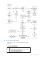
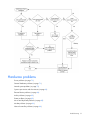
Troubleshooting flowcharts .......................................................................................................................... 61
Start diagnosis flowchart ................................................................................................................... 62
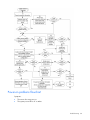
General diagnosis flowchart.............................................................................................................. 62
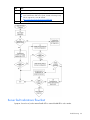
Power-on problems flowchart ............................................................................................................. 64
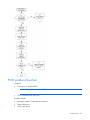
POST problems flowchart .................................................................................................................. 66
OS boot problems flowchart .............................................................................................................. 68
Server fault indications flowchart ....................................................................................................... 69
Hardware problems ................................................................................................................................... 71
Power problems ............................................................................................................................... 72
General hardware problems ............................................................................................................. 73
Internal system problems ................................................................................................................... 75
System open circuits and short circuits ................................................................................................ 83
External device problems .................................................................................................................. 84
Audio problems ............................................................................................................................... 85
Printer problems ............................................................................................................................... 85
Mouse and keyboard problems ......................................................................................................... 85
Modem problems ............................................................................................................................. 86
Network controller problems ............................................................................................................. 88
Software problems ..................................................................................................................................... 89
Operating system problems ............................................................................................................... 89
Operating system updates ................................................................................................................. 90
Restoring to a backed-up version ....................................................................................................... 90
When to reconfigure or reload software ............................................................................................. 91
Linux operating systems .................................................................................................................... 91
Application software problems .......................................................................................................... 91
Firmware maintenance ............................................................................................................................... 92
Types of ROM.................................................................................................................................. 92
ROMPaq utility diskette or USB drive key ............................................................................................ 93
Current firmware versions ................................................................................................................. 93
Updating firmware ........................................................................................................................... 94
Drivers ............................................................................................................................................ 94
Contacting HP ........................................................................................................................................... 94
Contacting HP technical support or an authorized reseller .................................................................... 94
Server information you need.............................................................................................................. 95
Operating system information you need ............................................................................................. 95
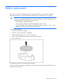
Battery replacement .................................................................................................................... 98
Regulatory compliance notices ..................................................................................................... 99
Regulatory compliance identification numbers ............................................................................................... 99
Federal Communications Commission notice ................................................................................................. 99
FCC rating label .............................................................................................................................. 99
Class A equipment ........................................................................................................................... 99
Class B equipment............................................................................................................................ 99
Declaration of conformity for products marked with the FCC logo, United States only...................................... 100
Modifications ........................................................................................................................................... 100
Cables .................................................................................................................................................... 100
Canadian notice (Avis Canadien) .............................................................................................................. 101
European Union regulatory notice .............................................................................................................. 101
Disposal of waste equipment by users in private households in the European Union ........................................ 101
Japanese notice ....................................................................................................................................... 102
BSMI notice ............................................................................................................................................. 103
Korean notice .......................................................................................................................................... 103
Laser compliance ..................................................................................................................................... 103
Battery replacement notice ........................................................................................................................ 104
Taiwan battery recycling notice ................................................................................................................. 104
Power cord statement for Japan ................................................................................................................. 104
Acoustics statement for Germany (Geräuschemission) .................................................................................. 104
Electrostatic discharge ............................................................................................................... 105
Preventing electrostatic discharge .............................................................................................................. 105
Grounding methods to prevent electrostatic discharge .................................................................................. 105
Technical support ...................................................................................................................... 106
HP contact information .............................................................................................................................. 106
Before you contact HP .............................................................................................................................. 106
Customer Self Repair ................................................................................................................................ 106
Acronyms and abbreviations ...................................................................................................... 114
Index ....................................................................................................................................... 118
Server operations
Power up the server
To power up the server, press the Power On/Standby button.
Power down the server
WARNING: To reduce the risk of personal injury, electric shock, or damage to the
equipment, remove the power cord to remove power from the server. The front panel Power
On/Standby button does not completely shut off system power. Portions of the power supply
and some internal circuitry remain active until AC power is removed.
IMPORTANT: If installing a hot-plug device, it is not necessary to power down the server.
1.
Back up the server data.
2.
Shut down the operating system as directed by the operating system documentation.
3.
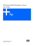
Press the Power On/Standby button to place the server in standby mode. When the server activates
standby power mode, the system power LED changes to amber.
4.
Disconnect the power cords.
The system is now without power.
Access panel
WARNING: To reduce the risk of personal injury from hot surfaces, allow the drives and the
internal system components to cool before touching them.
CAUTION: Do not operate the server for long periods with the access panel open or
removed. Operating the server in this manner results in improper airflow and improper
cooling that can lead to thermal damage.
1.
Power down the server (on page 6).
2.
Extend the server from the rack, if applicable.
3.
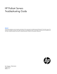
Loosen the two thumbscrews located on the server rear panel, if applicable.
4.
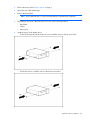
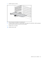
Slide the access panel back about 1.5 cm (0.5 in).
5.
Lift and remove the access panel.
To install the component, reverse the removal procedure.
Server operations
6
Server setup
Optional installation services
Delivered by experienced, certified engineers, HP Care Pack services help you keep your servers up and
running with support packages tailored specifically for HP ProLiant systems. HP Care Packs let you
integrate both hardware and software support into a single package. A number of service level options
are available to meet your needs.
HP Care Pack Services offer upgraded service levels to expand the standard product warranty with easyto-buy, easy-to-use support packages that help you make the most of your server investments. Some of the
Care Pack services are:
•
•
•
•
Hardware support
o
6-hour call-to-repair
o
4-hour 24x7 same day
o
4-hour same business day
Software support
o
Microsoft®
o
Linux
Integrated hardware and software support
o
Critical Service
o
Proactive 24
o
Support Plus
o
Support Plus 24
Startup and implementation services for both hardware and software
For more information on Care Packs, refer to the HP website
(http://www.hp.com/hps/carepack/servers/cp_proliant.html).
Rack planning resources
The rack resource kit ships with all HP branded or Compaq branded 9000, 10000, and H9 series racks.
For more information on the content of each resource, refer to the rack resource kit documentation.
If you intend to deploy and configure multiple servers in a single rack, refer to the white paper on highdensity deployment at the HP website (http://www.hp.com/products/servers/platforms).
Optimum environment
When installing the server, select a location that meets the environmental standards described in this
section.
Server setup 7
Space and airflow requirements
Tower server
In a tower configuration, leave at least a 7.6-cm (3-in) clearance space at the front and back of the server
for proper ventilation.
Rack server
To allow for servicing and adequate airflow, observe the following space and airflow requirements when
deciding where to install a rack:
•
Leave a minimum clearance of 63.5 cm (25 in) in front of the rack.
•
Leave a minimum clearance of 76.2 cm (30 in) behind the rack.
•
Leave a minimum clearance of 121.9 cm (48 in) from the back of the rack to the back of another
rack or row of racks.
HP servers draw in cool air through the front door and expel warm air through the rear door. Therefore,
the front and rear rack doors must be adequately ventilated to allow ambient room air to enter the
cabinet, and the rear door must be adequately ventilated to allow the warm air to escape from the
cabinet.
CAUTION: To prevent improper cooling and damage to the equipment, do not block the
ventilation openings.
When vertical space in the rack is not filled by a server or rack component, the gaps between the
components cause changes in airflow through the rack and across the servers. Cover all gaps with
blanking panels to maintain proper airflow.
CAUTION: Always use blanking panels to fill empty vertical spaces in the rack. This
arrangement ensures proper airflow. Using a rack without blanking panels results in improper
cooling that can lead to thermal damage.
The 9000 and 10000 Series Racks provide proper server cooling from flow-through perforations in the
front and rear doors that provide 64 percent open area for ventilation.
CAUTION: When using a Compaq branded 7000 Series rack, you must install the high
airflow rack door insert [P/N 327281-B21 (42U) or P/N 157847-B21 (22U)] to provide
proper front-to-back airflow and cooling.
CAUTION: If a third-party rack is used, observe the following additional requirements to
ensure adequate airflow and to prevent damage to the equipment:
• Front and rear doors—If the 42U rack includes closing front and rear doors, you must
allow 5,350 sq cm (830 sq in) of holes evenly distributed from top to bottom to permit
adequate airflow (equivalent to the required 64 percent open area for ventilation).
• Side—The clearance between the installed rack component and the side panels of the rack
must be a minimum of 7 cm (2.75 in).
Temperature requirements
To ensure continued safe and reliable equipment operation, install or position the system in a wellventilated, climate-controlled environment.
Server setup 8
The maximum recommended ambient operating temperature (TMRA) for most server products is 35°C
(95°F). The temperature in the room where the rack is located must not exceed 35°C (95°F).
CAUTION: To reduce the risk of damage to the equipment when installing third-party options:
• Do not permit optional equipment to impede airflow around the server or to increase the
internal rack temperature beyond the maximum allowable limits.
• Do not exceed the manufacturer’s TMRA.
Power requirements
Installation of this equipment must comply with local and regional electrical regulations governing the
installation of information technology equipment by licensed electricians. This equipment is designed to
operate in installations covered by NFPA 70, 1999 Edition (National Electric Code) and NFPA-75, 1992
(code for Protection of Electronic Computer/Data Processing Equipment). For electrical power ratings on
options, refer to the product rating label or the user documentation supplied with that option.
WARNING: To reduce the risk of personal injury, fire, or damage to the equipment, do not
overload the AC supply branch circuit that provides power to the rack. Consult the electrical
authority having jurisdiction over wiring and installation requirements of your facility.
CAUTION: Protect the server from power fluctuations and temporary interruptions with a
regulating uninterruptible power supply (UPS). This device protects the hardware from
damage caused by power surges and voltage spikes and keeps the system in operation
during a power failure.
When installing more than one server, you may need to use additional power distribution devices to
safely provide power to all devices. Observe the following guidelines:
•
Balance the server power load between available AC supply branch circuits.
•
Do not allow the overall system AC current load to exceed 80 percent of the branch circuit AC
current rating.
•
Do not use common power outlet strips for this equipment.
•
Provide a separate electrical circuit for the server.
Electrical grounding requirements
The server must be grounded properly for proper operation and safety. In the United States, you must
install the equipment in accordance with NFPA 70, 1999 Edition (National Electric Code), Article 250,
as well as any local and regional building codes. In Canada, you must install the equipment in
accordance with Canadian Standards Association, CSA C22.1, Canadian Electrical Code. In all other
countries, you must install the equipment in accordance with any regional or national electrical wiring
codes, such as the International Electrotechnical Commission (IEC) Code 364, parts 1 through 7.
Furthermore, you must be sure that all power distribution devices used in the installation, such as branch
wiring and receptacles, are listed or certified grounding-type devices.
Because of the high ground-leakage currents associated with multiple servers connected to the same
power source, HP recommends the use of a PDU that is either permanently wired to the building’s branch
circuit or includes a nondetachable cord that is wired to an industrial-style plug. NEMA locking-style plugs
or those complying with IEC 60309 are considered suitable for this purpose. Using common power outlet
strips for the server is not recommended.
Server setup 9
Rack warnings
WARNING: To reduce the risk of personal injury or damage to the equipment, be sure that:
• The leveling jacks are extended to the floor.
• The full weight of the rack rests on the leveling jacks.
• The stabilizing feet are attached to the rack if it is a single-rack installation.
• The racks are coupled together in multiple-rack installations.
• Only one component is extended at a time. A rack may become unstable if more than one
component is extended for any reason.
WARNING: To reduce the risk of personal injury or equipment damage when unloading a
rack:
• At least two people are needed to safely unload the rack from the pallet. An empty 42U
rack can weigh as much as 115 kg (253 lb), can stand more than 2.1 m (7 ft) tall, and
may become unstable when being moved on its casters.
• Never stand in front of the rack when it is rolling down the ramp from the pallet. Always
handle the rack from both sides.
Installing hardware options
Install any hardware options before initializing the server. For options installation information, refer to the
option documentation. For server-specific information, refer to "Hardware options installation (on page
11)."
Powering up and configuring the server
To power up the server, press the Power On/Standby button.
For detailed information on configuring the server, see the server installation sheet.
Installing the operating system
To operate properly, the server must have a supported operating system. For the latest information on
supported operating systems, refer to the HP website (http://www.hp.com/go/supportos).
To install an operating system on the server, insert the operating system CD into the CD-ROM drive and
reboot the server. This process may require you to obtain additional drivers from the Easy Set-up CD or
the support CD shipped with the server, or the CD that shipped with the option. The drivers may have
updates that are available on the HP website (http://www.hp.com/support).
Follow the on-screen instructions to begin the installation process.
Registering the server
To register the server, refer to the HP Registration website (http://register.hp.com).
Server setup 10
Hardware options installation
Introduction
If more than one option is being installed, read the installation instructions for all the hardware options
and identify similar steps to streamline the installation process.
WARNING: To reduce the risk of personal injury from hot surfaces, allow the drives and the
internal system components to cool before touching them.
CAUTION: To prevent damage to electrical components, properly ground the server before
beginning any installation procedure. Improper grounding can cause electrostatic discharge.
Processor option
This section provides the following procedures:
•
Installing a processor in HP ProLiant ML150 Generation 3 and Generation 5 Servers (on page 11)
•
Installing a processor in HP ProLiant ML110 (G2, G3, and G4) and ProLiant ML150 Generation 2
Servers (on page 14)
•
Installing a processor in HP ProLiant ML110 Generation 5 Servers (on page 16)
•
Installing a processor in HP ProLiant ML115 and ML115 Generation 5 Servers (on page 17)
For more information on installing a processor in a specific server, see the documentation that ships with
the processor option kit.
Installing a processor in HP ProLiant ML150 Generation 3 and
Generation 5 Servers
HP ProLiant ML150 Generation 3 and Generation 5 Servers support single- and dual-processor operation.
With two processors installed, the server supports boot functions through the processor installed in
processor socket 1. However, if processor 1 fails, the system automatically boots from processor 2 and
provides a processor failure message.
The server uses embedded PPMs as DC-to-DC converters to provide the proper power to each processor.
CAUTION: To prevent possible server malfunction, do not mix processors of different speeds
or cache sizes. Refer to the label on the processor heatsink for a description of the processor.
IMPORTANT: Processor socket 1 must be populated at all times or the server does not
function.
To install a processor:
1.
Power down the server (on page 6).
Hardware options installation
11
2.
Extend the server from the rack.
3.
Remove the access panel ("Access panel" on page 6).
4.
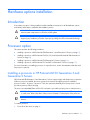
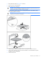
Open the processor retaining latch and the processor socket retaining bracket.
5.
Remove the processor socket protective cover.
IMPORTANT: Be sure the processor remains inside the processor installation tool.
Hardware options installation
12
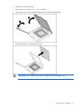
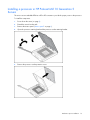
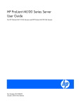
6.
If the processor has separated from the installation tool, carefully re-insert the processor in the tool.
7.
Align the processor installation tool with the socket and install the processor.
Hardware options installation
13
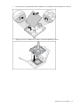
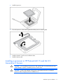
8.
Press down firmly until the processor installation tool clicks and separates from the processor, and
then remove the processor installation tool.
9.
Close the processor socket retaining bracket and the processor retaining latch.
10.
Install the heatsink. See the server installation sheet.
11.
Install the access panel.
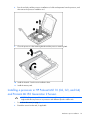
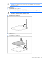
Installing a processor in HP ProLiant ML110 (G2, G3, and G4)
and ProLiant ML150 Generation 2 Servers
CAUTION: To prevent possible server malfunction and damage to the equipment, do not mix
single- and dual-core processors or processors with different speeds or cache sizes.
1.
Power down the server (on page 6).
2.
Extend the server from the rack, if applicable.
Hardware options installation
14
3.
Remove the access panel ("Access panel" on page 6).
4.
Open the processor retaining bracket.
5.
Release the processor locking lever.
CAUTION: Failure to completely open the processor locking lever prevents the processor from
seating during installation, leading to hardware damage.
6.
Install the processor and close the processor retaining bracket. Refer to the installation sheet for
server-specific installation instructions.
CAUTION: To prevent possible server malfunction or damage to the equipment, be sure to
completely close the processor locking lever.
7.
Install the heatsink. Refer to the installation sheet for server-specific installation instructions.
8.
Install the PPM (if applicable). Refer to the server hood labels or user documentation for specific
information on how to install a PPM.
9.
Install the access panel.
Hardware options installation
15
Installing a processor in HP ProLiant ML110 Generation 5
Servers
The server uses an embedded PPM as a DC-to-DC converter to provide the proper power to the processor.
To install the component:
1.
Power down the server (on page 6).
2.
Extend the server from the rack.
3.
Remove the access panel ("Access panel" on page 6).
4.
Open the processor retaining latch and the processor socket retaining bracket.
5.
Remove the processor socket protective cover.
Hardware options installation
16
6.
Install the processor.
7.
Close the processor socket retaining bracket and the processor retaining latch.
8.
Install the heatsink. See the server installation sheet.
9.
Install the access panel.
Installing a processor in HP ProLiant ML115 and ML115
Generation 5 Servers
CAUTION: To avoid damage to the processor and system board, only authorized personnel
should attempt to replace or install the processor in this server.
CAUTION: To help avoid damage to the processor and system board, do not install the
processor without using the processor installation tool.
Hardware options installation
17
IMPORTANT: If installing a processor with a faster speed, update the system ROM before
installing the processor.
To install a processor:
1.
Power down the server (on page 6).
2.
Remove the access panel ("Access panel" on page 6).
3.
Remove the heatsink fan and the heatsink. For more information, see the server installation sheet.
CAUTION: Failure to completely open the processor locking lever prevents the processor from
seating during installation, leading to hardware damage.
4.
Open the processor locking lever.
5.
Install the processor.
6.
Close the processor locking lever.
Hardware options installation
18
CAUTION: To prevent possible server malfunction or damage to the equipment, be sure to
completely close the processor locking lever.
7.
Install the heatsink and the heatsink fan. For more information, see the server installation sheet.
8.
Install the access panel.
SAS or SATA hard drive options
Some HP ProLiant 100 Series servers support SAS and SATA drives depending on the controller
configuration.
ProLiant server
SATA support
SAS support
Maximum drives
ProLiant ML110 G4 and G5 Servers
Embedded
Optional HBA
4
ProLiant ML115 and ML115 G5
Servers
Embedded
Optional HBA
4
ProLiant ML150 G3 Server
Embedded
Optional HBA
6
ProLiant ML150 G5 Server
Embedded
Optional HBA
8
For optimal performance, avoid mixing SAS and SATA hard drives.
CAUTION: To prevent improper cooling and thermal damage, do not operate the server
unless all bays are populated with either a component or a blank.
IMPORTANT: If only one hard drive is installed, install it in the bay with the lowest device
number. For device numbering and drive installation guidelines, refer to "SAS and SATA hard
drive guidelines (on page 59)."
IMPORTANT: Some ProLiant 100 Series servers support hot-plug functionality when an
optional SAS or SATA Smart Array controller is installed. For more information, see the
installation sheet that ships with the server.
To install the component:
1.
Power down the server (on page 6).
2.
Open the bezel, if applicable.
Hardware options installation
19
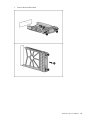
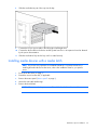
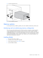
3.
Remove the hard drive blank.
Hardware options installation
20
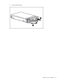
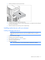
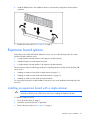
4.
Prepare the hard drive.
Hardware options installation
21
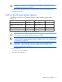
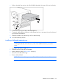
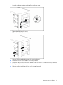
5.
Install the hard drive.
6.
Close the bezel.
7.
Resume normal server operations.
8.
Determine the status of the hard drive from the hot-plug SAS hard drive LED combinations ("SAS and
SATA hard drive LED combinations" on page 60).
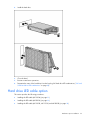
Hard drive LED cable option
This section provides the following procedures:
•
Installing the LED cable (ML110 G4) (on page 23)
•
Installing the LED cable (ML150 G3) (on page 26)
•
Installing the LED cable (ML110 G5, ML115 G5, and ML150 G5) (on page 28)
Hardware options installation
22
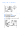
Installing the LED cable (ML110 G4)
Connector location (ML110 G4)
Cabling an HP Smart Array E200 controller card (ML110 G4)
1.
Power down the server (on page 6).
2.
Remove the access panel ("Access panel" on page 6).
3.
Install an HP Smart Array E200 controller card.
For more information, see the documentation that ships with the option and see "Expansion board
options (on page 41)."
4.
Connect the LED cable to the controller card and to the system board.
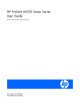
5.
Open the cable clamp.
Hardware options installation
23
6.
Secure the cable with the cable clamp.
7.
Install the access panel.
8.
Power up the server (on page 6).
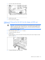
Cabling an HP 8 Internal Port SAS/SATA Host Bus Adapter with RAID card
(ML110 G4)
IMPORTANT: The LED cable must be connected to the HP 8 Internal Port SAS/SATA Host Bus
Adapter card before the card is installed in the server. If the card is already installed, remove
it before connecting the cable. For more information, see the HP ProLiant ML110 Generation
4 Server Maintenance and Service Guide.
1.
Power down the server (on page 6).
2.
Remove the access panel ("Access panel" on page 6).
3.
Connect the LED cable to the card.
4.
Install the card.
For more information, see the documentation that ships with the option and see "Expansion board
options (on page 41)."
5.
Connect the LED cable to the system board.
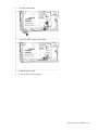
Hardware options installation
24
6.
Open the cable clamp.
7.
Secure the cable with the cable clamp.
8.
Install the access panel.
9.
Power up the server (on page 6).
Hardware options installation
25
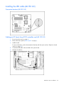
Installing the LED cable (ML150 G3)
Connector location (ML150 G3)
Cabling an HP Smart Array E200 controller card (ML150 G3)
1.
Power down the server (on page 6).
2.
Remove the access panel ("Access panel" on page 6).
3.
Install the card.
For more information, see the documentation that ships with the option and see "Expansion board
options (on page 41)."
4.
Connect the LED cable to the card and to the system board.
5.
Unfasten the cable tie.
Hardware options installation
26
6.
Secure the cable with the cable tie.
7.
Install the access panel.
8.
Power up the server (on page 6).
Cabling an HP 8 Internal Port SAS/SATA Host Bus Adapter with RAID card
(ML150 G3)
1.
Power down the server (on page 6).
2.
Remove the access panel ("Access panel" on page 6).
3.
Install the card.
For more information, see the documentation that ships with the option and see "Expansion board
options (on page 41)."
4.
Connect the LED cable to the card and to the system board.
5.
Unfasten the cable tie.
Hardware options installation
27
6.
Secure the cable with the cable tie.
7.
Install the access panel.
8.
Power up the server (on page 6).
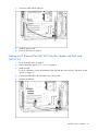
Installing the LED cable (ML110 G5, ML115 G5, and ML150
G5)
Connector locations (ML110 G5, ML115 G5, and ML150 G5)
•
HP ProLiant ML110 Generation 5 Server
Hardware options installation
28
•
HP ProLiant ML115 Server
•
HP ProLiant ML115 Generation 5 Server
•
HP ProLiant ML150 Generation 5 Server
Hardware options installation
29
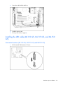
•
HP 4 Internal Port SAS HBA SC40Ge with RAID storage controller card
•
HP Int-4 Ext port, PCI-E SAS RAID storage controller card
Hardware options installation
30
•
HP Smart Array E200 controller card
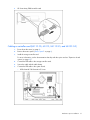
Cabling a controller card (ML110 G5, ML115, ML115 G5, and ML150 G5)
1.
Power down the server (on page 6).
2.
Remove the access panel ("Access panel" on page 6).
3.
Install the storage controller card.
For more information, see the documentation that ships with the option and see "Expansion board
options (on page 41)."
4.
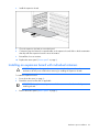
Connect the LED cable to the storage controller card.
5.
Secure the cable with the cable clamp.
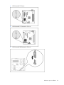
6.
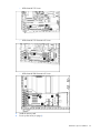
Connect the LED cable to the system board.
o
HP ProLiant ML110 Generation 5 Server
Hardware options installation
31
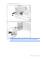
o
HP ProLiant ML115 Server
o
HP ProLiant ML115 Generation 5 Server
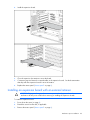
o
HP ProLiant ML150 Generation 5 Server
7.
Install the access panel.
8.
Power up the server (on page 6).
Hardware options installation
32
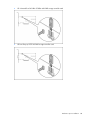
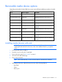
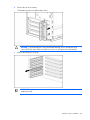
Removable media device options
Depending on the model, ProLiant 100 Series servers require different installation procedures for media
devices.
Server
Device support
Procedure
ProLiant ML110 G2 Server
Half-height and full-height
Installing media devices with a media latch
(on page 36)
ProLiant ML110 G3 Server
Half-height
Installing media devices with screws (on
page 34)
ProLiant ML110 G4 Server
Half-height
Installing media devices with screws (on
page 34)
ProLiant ML110 G5 Server
Half-height
Installing media devices with screws (on
page 34)
ProLiant ML115 Server
Half-height
Installing media devices with screws (on
page 34)
ProLiant ML115 G5 Server
Half-height
Installing media devices with screws (on
page 34)
ProLiant ML150 G2 Server
Half-height
Installing media devices with rails (on page
33)
ProLiant ML150 G3 Server
Half-height and full-height
Installing media devices with screws (on
page 34)
ProLIant ML150 G5 Server
Half-height and full-height
Installing media devices with wire retainers
(on page 37)
Installing media devices with rails
NOTE: This process only represents one installation method. For specific instructions for
installing the media device into the server, refer to the installation sheet for your specific
server.
1.
Power down the server (on page 6).
2.
Extend the server from the rack, if applicable.
3.
Remove the access panel ("Access panel" on page 6).
4.
Access the removable media cage.
5.
Remove the bezel blank.
NOTE: HP recommends that you remove all bezel blanks to facilitate drive installation.
6.
Depending on the server, obtain the screws from one of the following locations:
o
Bezel blank
o
Chassis
o
Accessory kit
Hardware options installation
33
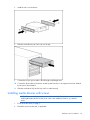
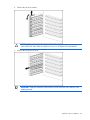
7.
Install the rails on to the device.
8.
Slide the media device part of the way into the bay.
9.
Connect the four-pin power cable to the full-height or half-height drive.
10.
Connect the device cable to the device and the system board or to an expansion board as directed
by the option documentation.
11.
Slide the media drive fully into the bay until it is seated securely.
Installing media devices with screws
NOTE: This process only represents one installation method. For specific instructions for
installing the media device into the server, refer to the installation sheet for your specific
server.
1.
Power down the server (on page 6).
2.
Extend the server from the rack, if applicable.
Hardware options installation
34
3.
Remove the access panel ("Access panel" on page 6).
4.
Access the removable media cage.
5.
Remove the bezel blank.
NOTE: HP recommends that you remove all bezel blanks to facilitate drive installation.
6.
7.
Depending on the server, obtain the screws from one of the following locations:
o
Bezel blank
o
Chassis
o
Accessory kit
Install the screws on the media device:
o
For the HP ProLiant ML110 Generation 5 Server, install the screws in the top screw holes.
o
For all other servers, install the screws in the bottom screw holes.
Hardware options installation
35
8.
Slide the media device part of the way into the bay.
9.
Connect the four-pin power cable to the full-height or half-height drive.
10.
Connect the device cable to the device and the system board or to an expansion board as directed
by the option documentation.
11.
Slide the media drive fully into the bay until it is seated securely.
Installing media devices with a media latch
NOTE: This process only represents one installation method. For specific instructions for
installing the media device into the server, refer to the installation sheet for your specific
server.
1.
Power down the server (on page 6).
2.
Extend the server from the rack, if applicable.
3.
Remove the access panel ("Access panel" on page 6).
4.
Access the removable media cage.
5.
Remove the bezel blank.
NOTE: HP recommends that you remove all bezel blanks to facilitate drive installation.
Hardware options installation
36
6.
Slide the media device into the bay until it clicks.
7.
Connect the four-pin power cable to the media drive.
8.
Connect the device cable to the device and the system board or to an expansion board, as directed
by the option documentation.
9.
Slide the media drive fully into the bay until it is seated securely.
Installing media devices with wire retainers
Installing a half-height media device
NOTE: This process only represents one installation method. For specific instructions for
installing the media device into the server, refer to the installation sheet for your specific
server.
1.
Power down the server (on page 6).
2.
Extend the server from the rack, if applicable.
3.
Remove the access panel ("Access panel" on page 6).
4.
Access the removable media cage.
5.
Remove the bezel blank.
NOTE: HP recommends that you remove all bezel blanks to facilitate drive installation.
Hardware options installation
37
6.
Release the media bay retainers and slide the half-height media device part of the way into the bay.
7.
Connect the four-pin power cable to the half-height drive.
8.
Connect the device cable to the device and the system board or to an expansion board, as directed
by the option documentation.
9.
Slide the media drive fully into the bay until it is seated securely.
10.
Close the media bay retainers.
Installing a full-height media device
NOTE: This process only represents one installation method. For specific instructions for
installing the media device into the server, refer to the installation sheet for your specific
server.
1.
Power down the server (on page 6).
2.
Extend the server from the rack, if applicable.
3.
Remove the access panel ("Access panel" on page 6).
4.
Access the removable media cage.
5.
Remove the bezel blank.
NOTE: HP recommends that you remove all bezel blanks to facilitate drive installation.
Hardware options installation
38
6.
Open the media bay retainers and install the media bay plate.
7.
Tighten the media bay plate screw.
8.
Remove the media bay support wire.
9.
Slide the full-height media device part of the way into the bay.
10.
Connect the four-pin power cable to the full-height device.
11.
Connect the device cable to the device and the system board or to an expansion board, as directed
by the option documentation.
12.
Slide the media drive fully into the bay until it is seated securely.
Hardware options installation
39
13.
Secure the media bay screws.
14.
Close the media bay retainers.
Memory options
For server-specific memory installation guidelines, refer to the installation sheet that ships with the server.
Interleaving and non-interleaving memory configuration
This server supports both interleaving and non-interleaving memory configurations. Interleaving memory
increases bandwidth by allowing simultaneous access to more than one block of data (for example,
overlapping Read-Writes). This is accomplished by dividing the system memory between pairs of DIMMs
and Writing-Reading blocks of data to/from both simultaneously. In order to take advantage of memory
interleaving, identical DIMMs must be installed in pairs. DIMMs can also be installed singularly in slot 1
only if memory interleaving is not desired.
Installing DIMMs
1.
Power down the server (on page 6).
2.
Extend the server from the rack, if applicable.
3.
Remove the access panel ("Access panel" on page 6).
4.
Open the DIMM slot latches.
Hardware options installation
40
5.
Install the DIMM. Refer to the installation sheet for server-specific configuration and population
guidelines.
6.
Replace the access panel ("Access panel" on page 6).
Expansion board options
Depending on the model, HP ProLiant 100 Series servers use one of the following methods to retain
expansion boards within the server:
•
A single expansion board retainer for all expansion boards (internal)
•
Individual retainers for each expansion board
•
A single expansion board retainer for all expansion boards (external)
This document provides the following procedures for installing expansion boards into HP ProLiant 100
Series servers:
•
Installing an expansion board with a single retainer (on page 41)
•
Installing an expansion board with individual retainers (on page 43)
•
Installing an expansion board with an external retainer
For server-specific expansion board installation instructions, refer to the installation sheet that ships with
the server.
Installing an expansion board with a single retainer
CAUTION: To prevent damage to the server or expansion boards, power down the server
and remove all AC power cords before removing or installing the expansion boards.
To install an expansion board:
1.
Power down the server (on page 6).
2.
Extend the server from the rack, if applicable.
3.
Remove the access panel ("Access panel" on page 6).
Hardware options installation
41
4.
Remove the slot cover retainer.
CAUTION: To prevent improper cooling and thermal damage, do not operate the server
unless all PCI slots have either an expansion slot cover or an expansion board installed.
5.
Remove the expansion slot cover.
IMPORTANT: It may be necessary to remove the slot cover next to the slot in which you are
installing a board.
Hardware options installation
42
6.
Install the expansion board.
7.
Close the expansion slot latch to secure the board.
8.
Connect any required internal or external cables to the expansion board. Refer to the documentation
that ships with the expansion board for more information.
9.
Reinstall the slot cover retainer.
10.
Replace the access panel ("Access panel" on page 6).
Installing an expansion board with individual retainers
CAUTION: To prevent damage to the server or expansion boards, power down the server
and remove all AC power cords before removing or installing the expansion boards.
To install an expansion board:
1.
Power down the server (on page 6).
2.
Extend the server from the rack, if applicable.
IMPORTANT: It may be necessary to remove the slot cover next to the slot in which you are
installing a board.
3.
Remove the access panel ("Access panel" on page 6).
Hardware options installation
43
4.
Remove the expansion slot cover.
CAUTION: To prevent improper cooling and thermal damage, do not operate the server
unless all PCI slots have either an expansion slot cover or an expansion board installed.
Hardware options installation
44
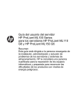
5.
Install the expansion board.
6.
Close the expansion slot retainer to secure the board.
7.
Connect any required internal or external cables to the expansion board. See the documentation
that ships with the expansion board for more information.
8.
Replace the access panel ("Access panel" on page 6).
Installing an expansion board with an external retainer
CAUTION: To prevent damage to the server or expansion boards, power down the server
and remove all AC power cords before removing or installing the expansion boards.
To install an expansion board:
1.
Power down the server (on page 6).
2.
Extend the server from the rack, if applicable.
3.
Remove the access panel ("Access panel" on page 6).
Hardware options installation
45
4.
Remove the slot cover retainer.
The thumbscrew may look different than shown.
CAUTION: To prevent improper cooling and thermal damage, do not operate the server
unless all PCI slots have either an expansion slot cover or an expansion board installed.
5.
Remove the expansion slot cover.
IMPORTANT: It may be necessary to remove the slot cover next to the slot in which you are
installing a board.
Hardware options installation
46
6.
Install the expansion board.
7.
Close the expansion slot latch to secure the board.
8.
Connect any required internal or external cables to the expansion board. Refer to the documentation
that ships with the expansion board for more information.
9.
Install the slot cover retainer.
10.
Install the access panel.
Hardware options installation
47
Server software and configuration utilities
ROMPaq utility
The ROMPaq utility enables you to upgrade the system firmware (BIOS). To upgrade the firmware, insert
a ROMPaq diskette into the diskette drive or ROMPaq USB Key into an available USB port and boot the
system. Online versions of the ROMPaq utility are also available for updating the system firmware.
The ROMPaq utility checks the system and provides a choice (if more than one exists) of available
firmware revisions.
For more information about the ROMPaq utility, see the HP website (http://www.hp.com/go/support).
HP Insight Diagnostics
The HP Insight Diagnostics utility displays information about the server hardware and tests the system to
be sure it is operating properly. The utility has online help and can be accessed using the Easy Set-up CD
or the support CD.
Keeping the system current
Drivers
HP drivers and utilities can be found on the Easy Set-up CD or the support CD. For the latest drivers and
information on supported operating systems, refer to the HP website (http://www.hp.com/support).
IMPORTANT: Always perform a backup before installing or updating device drivers.
Subscriber's choice
HP's Subscriber's Choice is a customizable subscription sign-up service that customers use to receive
personalized email product tips, feature articles, driver and support alerts, or other notifications.
To create a profile and select notifications, refer to the HP website
(http://www.hp.com/go/subscriberschoice).
Change control and proactive notification
HP offers Change Control and Proactive Notification to notify customers 30 to 60 days in advance of
upcoming hardware and software changes on HP commercial products.
For more information, refer to the HP website (http://www.hp.com/go/pcn).
Server software and configuration utilities
48
Embedded SATA RAID feature
HP provides the SATA RAID feature through use of the HP Storage Manager. For the embedded SATA
controller in the system, this feature enables the following RAID functionality:
•
RAID 0 and 1 for HP ProLiant ML110 G2, G3, G4, and G5 Servers; the HP ProLiant ML115 and
ML115 G5 Servers; and HP ProLiant ML150 G2 and G3 Servers
•
RAID 5 for the HP ProLiant ML115 and ML115 G5 Servers
Required hardware
Installing the Embedded SATA RAID driver requires a diskette drive or a CD-ROM drive.
In a Microsoft® Windows® OS environment, driver installation is supported only with a USB diskette
drive or LO100 Virtual Floppy for the following servers:
•
HP ProLiant ML110 G4 Server
•
HP ProLiant ML115 and ML115 G5 Servers
•
HP ProLiant ML150 G3 and G5 Servers
Some servers do not ship with these drives as standard hardware.
Diskette and CD-ROM drive options
To acquire a diskette drive option or CD-ROM drive option for a server, contact an HP authorized reseller.
For the name of the nearest HP authorized reseller:
•
In the United States, call 1-800-345-1518.
•
In Canada, call 1-800-263-5868.
•
In other locations, refer to the HP website (http://www.hp.com).
HP Integrated Lights-Out Virtual Floppy and CD-ROM drives
LO100 Advanced provides diskette drive and CD-ROM drive functionality through the LO100 Virtual
Floppy and CD-ROM features.
For detailed information about LO100 Advanced, refer to the HP Integrated Lights-Out User Guide on the
HP website (http://www.hp.com/servers/lights-out).
Creating a diskette image
Download the HP Embedded SATA RAID Controller driver and create a driver diskette using the
instructions on the HP website (http://h20000.www2.hp.com/bizsupport/TechSupport/Home.jsp). At the
website, click the link for "Support and Drivers."
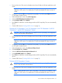
Installing the Embedded SATA RAID driver with a USB diskette drive
1.
Boot the server, and then press F10 to enter the ROM-Based Setup Utility (RBSU).
2.
Enable the Embedded SATA RAID option under the Advanced Options section.
3.
Exit RBSU. The server will reboot.
Server software and configuration utilities
49
4.
When prompted, press F8 to enter the HP Embedded SATA RAID Setup.
5.
Create an array, and then exit the HP Embedded SATA RAID Setup. The POST process will continue.
For information about creating arrays, see the following documentation:
6.
o
HP Embedded SATA RAID Controller User Guide on the HP website
(http://www.hp.com/support/E_SATA_RAID_C_UG_en)
o
nVidia ForceWare Software MediaShield User's Guide on the HP website
(http://h20000.www2.hp.com/bizsupport/TechSupport/Home.jsp)
Install the operating system ("Installing an operating system" on page 54).
For information about installing an operating system, see the documentation that shipped with the server.
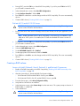
Installing the Embedded SATA RAID driver using Virtual Floppy
IMPORTANT: The LO100 option kit is required to use the Virtual Floppy feature. For more
information, see the HP ProLiant Lights-Out Remote Management User Guide on the HP
website (http://h20000.www2.hp.com/bizsupport/TechSupport/Home.jsp).
1.
Ensure that a network cable is connected to the LO100 NIC port on the rear of the server.
2.
Boot the server, and then press F10 to enter the ROM-Based Setup Utility (RBSU).
3.
Enable the Embedded SATA RAID option under the Advanced Options section.
4.
Exit RBSU. The server will reboot.
5.
Create the diskette.
For more information about Virtual Floppy, see the HP ProLiant Lights-Out Remote Management User
Guide on the HP website (http://h20000.www2.hp.com/bizsupport/TechSupport/Home.jsp).
6.
Insert the driver diskette into the remote PC diskette drive.
7.
Use LO100 Virtual Floppy to access the PC diskette drive.
For more information about Virtual Floppy, see the HP ProLiant Lights-Out Remote Management User
Guide on the HP website (http://h20000.www2.hp.com/bizsupport/TechSupport/Home.jsp).
8.
Power up the server (on page 6).
9.
Install the operating system ("Installing an operating system" on page 54).
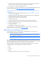
Configuring the SATA RAID feature
To configure the SATA RAID feature, do the following:
1.
Enable SATA RAID functionality in the BIOS Setup Utility ("Enabling SATA RAID functionality in the
BIOS Setup Utility" on page 50).
2.
Create a RAID volume ("Creating a RAID volume" on page 52).
Enabling SATA RAID functionality in the BIOS Setup Utility
ProLiant ML110 Generation 3 Server
CAUTION: Back up any data stored on the hard drives before proceeding. The configuration
process erases all data on the hard drives.
Server software and configuration utilities
50
1.
Power up the server. If the server is already powered, save all data, exit all open applications, and
restart.
NOTE: Enabling the RAID option in BIOS Setup Utility is only necessary for installation of the
RAID driver. If this option is not enabled, the OS loads the standard ATA driver from the OS
media.
2.
During POST, press the F10 key to launch BIOS Setup Utility. If you fail to press F10 before POST,
you will need to restart the server.
3.
In the Advanced menu screen, select IDE Configuration.
4.
Select the ATA/IDE Configuration>Enhanced field.
5.
Set the Configure SATA field to Enabled.
6.
Press F10, then select Yes to save the changes and close BIOS Setup Utility. The server automatically
reboots.
7.
Create a RAID volume ("Creating a RAID volume" on page 52).
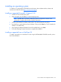
ProLiant ML110 Generation 2, ML110 Generation 4, ML110 Generation 5, ML150
Generation 2, and ML150 Generation 3 Servers
CAUTION: Back up any data stored on the hard drives before proceeding. The configuration
process erases all data on the hard drives.
1.
Power up the server. If the server is already powered, save all data, exit all open applications, and
restart.
NOTE: Enabling the RAID option in BIOS Setup Utility is only necessary for installation of the
RAID driver. If this option is not enabled, the OS loads the standard ATA driver from the OS
media.
2.
During POST, press the F10 key to launch BIOS Setup Utility. If you fail to press F10 before POST,
you will need to restart the server.
3.
In the Advanced menu screen, select Advanced Chipset Control.
4.
Set the Serial ATA field to Enabled.
5.
Select the SATA Controller Mode Option>Enhanced field.
6.
Set the SATA RAID Enable field to Enabled.
7.
Press F10, then select Yes to save the changes and close BIOS Setup Utility. The server automatically
reboots.
8.
Create a RAID volume ("Creating a RAID volume" on page 52).
ProLiant ML150 Generation 5 Servers
CAUTION: Back up any data stored on the hard drives before proceeding. The configuration
process erases all data on the hard drives.
1.
Power up the server. If the server is already powered, save all data, exit all open applications, and
restart.
NOTE: Enabling the RAID option in BIOS Setup Utility is only necessary for installation of the
RAID driver. If this option is not enabled, the OS loads the standard ATA driver from the OS
media.
Server software and configuration utilities
51
2.
During POST, press the F10 key to launch BIOS Setup Utility. If you fail to press F10 before POST,
you will need to restart the server.
3.
In the Advanced menu screen, select Hard Disk Configuration.
4.
Set the Configure Controller 1 field to RAID.
5.
Press F10, then select Yes to save the changes and close BIOS Setup Utility. The server automatically
reboots.
6.
Create a RAID volume ("Creating a RAID volume" on page 52).
ProLiant ML115 and ML115 G5 Servers
CAUTION: Back up any data stored on the hard drives before proceeding. The configuration
process erases all data on the hard drives.
1.
Power up the server. If the server is already powered, save all data, exit all open applications, and
restart.
NOTE: Enabling the RAID option in BIOS Setup Utility is only necessary for installation of the
RAID driver. If this option is not enabled, the OS loads the standard ATA driver from the OS
media.
2.
During POST, press the F10 key to launch BIOS Setup Utility. If you fail to press F10 before POST,
you will need to restart the server.
3.
In the Advanced menu screen, select HDD Configuration.
4.
Select the SATA RAID Setup field.
5.
Set the SATA RAID Function field to Enabled.
6.
Set the appropriate SATA channels for RAID to Enabled.
7.
Press F10, then select OK to save the changes and close BIOS Setup Utility. The server automatically
reboots.
8.
Create a RAID volume ("Creating a RAID volume" on page 52).
Creating a RAID volume
Servers with Intel® Celeron®, Xeon®, Pentium® 4, and Pentium® D processors
1.
Enable SATA RAID functionality in the BIOS Setup Utility ("Enabling SATA RAID functionality in the
BIOS Setup Utility" on page 50).
2.
After the system reboots, activate the RAID Configuration Utility:
o
For ProLiant ML110 G2 and ML150 G2 Servers, press CTRL+A.
o
For ProLiant ML110 G3, G4, G5, and ML150 G3 Servers, press F8.
3.
From the Option menu, select Array Configuration Utility.
4.
Verify that two SATA drives are installed.
5.
In the Main menu screen, select Create Array from the main menu. The system prompts a selection of
RAID 0, RAID 1, or RAID 10.
6.
Select a RAID level.
CAUTION: Back up any data stored on the hard drives before proceeding. The configuration
process erases all data on the hard drives.
Server software and configuration utilities
52
7.
Press Esc. The system automatically configures the RAID level, erasing all existing data on the hard
drives. This process can take up to 50 minutes, depending on drive capacity.
8.
After configuration is complete, press Esc to exit the utility.
For more information on configuring the SATA RAID feature, see the HP Embedded SATA RAID Controller
User Guide on the HP website (http://www.hp.com/support/E_SATA_RAID_C_UG_en).
Servers with AMD Opteron™, AMD Athlon™, and AMD Sempron™ processors and
nVidia chipset
1.
Enable SATA RAID functionality in the BIOS Setup Utility ("Enabling SATA RAID functionality in the
BIOS Setup Utility" on page 50).
2.
After the system reboots, the Option ROM status message appears on the screen. Press F8 to enter
the nVidia MediaShield Utility Option ROM user interface.
3.
Use the up and down arrow keys to select the RAID mode.
4.
Press Tab to select Free Disks.
5.
Use the up and down arrow keys to select the disks on which the array will be created.
6.
Use the left and right arrow keys to move the selected drives to the New Array Disks window.
7.
Press F7 to begin creating a new array.
8.
Press Y to clear disk data.
9.
Press Ctrl+X to exit the Option ROM user interface.
For more information on configuring the SATA RAID feature, see the nVidia ForceWare Software
MediaShield User's Guide on the HP website (http://www.hp.com).
USB diskette and CD-ROM drives
For driver installation purposes, a USB diskette drive and USB CD-ROM drive are sufficient, unless
otherwise indicated in driver-specific documentation.
NOTE: Do not use a USB drive key in place of the diskette drive. The OS does not support
driver installation from a USB drive key.
NOTE: HP recommends the use of HP standard USB disk drives.
HP provides both standard USB 2.0 support and legacy USB 2.0 support. Standard support is provided
by the OS through the appropriate USB device drivers. Before the OS loads, HP provides support for USB
devices through legacy USB support, which is enabled by default in the system ROM.
Legacy USB support provides USB functionality in environments where USB support is not available
normally. Specifically, HP provides legacy USB functionality for the following:
•
POST
•
RBSU
•
Diagnostics
•
DOS
•
Operating environments which do not provide native USB support
Server software and configuration utilities
53
Installing an operating system
To install an OS, download the SATA RAID driver and create a driver diskette with the software and
instructions from the HP website (http://www.hp.com/support).
Installing a supported Microsoft® Windows® OS
1.
Insert the OS CD and reboot the system.
2.
When prompted, press the F6 key to install a third-party driver.
NOTE: Press F6 within 5 seconds to enable the system to recognize the controller. If the
system fails to recognize the controller, restart this procedure.
3.
Insert the SATA RAID driver diskette created earlier. The system prompts the next action.
4.
Press the S key to specify the driver from the diskette. Then, press the Enter key. The OS searches the
diskette for a suitable driver.
5.
After locating the Adaptec Embedded Serial ATA HostRAID driver, press Enter.
6.
Follow the remaining on-screen instructions to complete the installation.
Installing a supported Linux or NetWare OS
To install a supported Linux or NetWare OS when using the HP Embedded SATA RAID controller, refer to
the OS documentation.
Server software and configuration utilities
54
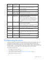
Troubleshooting
Pre-diagnostic steps
WARNING: To avoid potential problems, ALWAYS read the warnings and cautionary
information in the server documentation before removing, replacing, reseating, or modifying
system components.
IMPORTANT: This guide provides information for multiple servers. Some information may not
apply to the server you are troubleshooting. Refer to the server documentation for information
on procedures, hardware options, software tools, and operating systems supported by the
server.
1.
Review the important safety information (on page 55).
2.
Gather symptom information (on page 57).
3.
Prepare the server for diagnosis.
4.
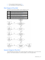
Use the Start diagnosis flowchart (on page 62) to begin the diagnostic process.
Important safety information
Familiarize yourself with the safety information in the following sections before troubleshooting the server.
Important safety information
Before servicing this product, read the Important Safety Information document provided with the server.
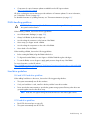
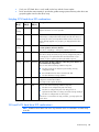
Symbols on equipment
The following symbols may be placed on equipment to indicate the presence of potentially hazardous
conditions.
This symbol indicates the presence of hazardous energy circuits or electric shock
hazards. Refer all servicing to qualified personnel.
WARNING: To reduce the risk of injury from electric shock hazards, do not open this
enclosure. Refer all maintenance, upgrades, and servicing to qualified personnel.
This symbol indicates the presence of electric shock hazards. The area contains no
user or field serviceable parts. Do not open for any reason.
WARNING: To reduce the risk of injury from electric shock hazards, do not open this
enclosure.
This symbol on an RJ-45 receptacle indicates a network interface connection.
WARNING: To reduce the risk of electric shock, fire, or damage to the equipment,
do not plug telephone or telecommunications connectors into this receptacle.
Troubleshooting
55
This symbol indicates the presence of a hot surface or hot component. If this surface
is contacted, the potential for injury exists.
WARNING: To reduce the risk of injury from a hot component, allow the surface to
cool before touching.
This symbol indicates that the component exceeds the recommended weight for one
individual to handle safely.
20.41 - 27.22
kg
47.18 - 60 lb
WARNING: To reduce the risk of personal injury or damage to the equipment,
observe local occupational health and safety requirements and guidelines for
manual material handling.
These symbols, on power supplies or systems, indicate that the equipment is
supplied by multiple sources of power.
WARNING: To reduce the risk of injury from electric shock, remove all power
cords to completely disconnect power from the system.
Warnings and cautions
WARNING: Only authorized technicians trained by HP should attempt to repair this
equipment. All troubleshooting and repair procedures are detailed to allow only
subassembly/module-level repair. Because of the complexity of the individual boards and
subassemblies, no one should attempt to make repairs at the component level or to make
modifications to any printed wiring board. Improper repairs can create a safety hazard.
WARNING: To reduce the risk of personal injury or damage to the equipment, be sure that:
• The leveling feet are extended to the floor.
• The full weight of the rack rests on the leveling feet.
• The stabilizing feet are attached to the rack if it is a single-rack installation.
• The racks are coupled together in multiple-rack installations.
• Only one component is extended at a time. A rack may become unstable if more than one
component is extended for any reason.
WARNING: To reduce the risk of electric shock or damage to the equipment:
• Do not disable the power cord grounding plug. The grounding plug is an important safety
feature.
• Plug the power cord into a grounded (earthed) electrical outlet that is easily accessible at
all times.
• Unplug the power cord from the power supply to disconnect power to the equipment.
• Do not route the power cord where it can be walked on or pinched by items placed
against it. Pay particular attention to the plug, electrical outlet, and the point where the
cord extends from the server.
Troubleshooting
56
WARNING: To reduce the risk of personal injury or damage to the equipment:
20.41 - 27.22
kg
47.18 - 60 lb
• Observe local occupation health and safety requirements and guidelines for
manual handling.
• Obtain adequate assistance to lift and stabilize the chassis during installation or
removal.
• The server is unstable when not fastened to the rails.
• When mounting the server in a rack, remove the power supplies and any other
removable module to reduce the overall weight of the product.
CAUTION: To properly ventilate the system, you must provide at least 7.6 cm (3.0 in) of
clearance at the front and back of the server.
CAUTION: The server is designed to be electrically grounded (earthed). To ensure proper
operation, plug the AC power cord into a properly grounded AC outlet only.
Symptom information
Before troubleshooting a server problem, collect the following information:
•
What events preceded the failure? After which steps does the problem occur?
•
What has been changed since the time the server was working?
•
Did you recently add or remove hardware or software? If so, did you remember to change the
appropriate settings in the server setup utility, if necessary?
•
How long has the server exhibited problem symptoms?
•
If the problem occurs randomly, what is the duration or frequency?
To answer these questions, the following information may be useful:
•
Run HP Insight Diagnostics (on page 48) and use the survey page to view the current configuration
or to compare it to previous configurations.
•
Refer to your hardware and software records for information.
•
Refer to server LEDs and their statuses.
Preparing the server for diagnosis
1.
Be sure the server is in the proper operating environment with adequate power, air conditioning,
and humidity control. Refer to the server documentation for required environmental conditions.
2.
Record any error messages displayed by the system.
3.
Remove all diskettes and CDs from the media drives.
4.
Power down the server and peripheral devices if you will be diagnosing the server offline. Always
perform an orderly shutdown, if possible. This means you must:
a. Exit any applications.
b. Exit the operating system.
c.
5.
Power down the server (on page 6).
Disconnect any peripheral devices not required for testing (any devices not necessary to power up
the server). Do not disconnect the printer if you want to use it to print error messages.
Troubleshooting
57
6.
Collect all tools and utilities, such as a Torx screwdriver, loopback adapters, ESD wrist strap, and
software utilities, necessary to troubleshoot the problem.
HP recommends you have access to the server documentation for server-specific information.
Common problem resolution
Loose connections (on page 58)
Service notifications (on page 58)
Firmware updates (on page 58)
DIMM handling guidelines (on page 59)
Hard drive guidelines ("SAS and SATA hard drive guidelines" on page 59, on page 59)
Hot-plug SCSI hard drive LED combinations (on page 60)
SAS and SATA hard drive LED combinations (on page 60)
Loose connections
Action:
•
Be sure all power cords are securely connected.
•
Be sure all cables are properly aligned and securely connected for all external and internal
components.
•
Remove and check all data and power cables for damage. Be sure no cables have bent pins or
damaged connectors.
•
If a fixed cable tray is available for the server, be sure the cords and cables connected to the server
are routed correctly through the tray.
•
Be sure each device is properly seated. Avoid bending or flexing circuit boards when reseating
components.
•
If a device has latches, be sure they are completely closed and locked.
•
Check any interlock or interconnect LEDs that may indicate a component is not connected properly.
•
If problems continue to occur, remove and reinstall each device, checking the connectors and sockets
for bent pins or other damage.
Service notifications
To view the latest service notifications, refer to the HP website (http://www.hp.com/go/bizsupport).
Select the appropriate server model, and then click the Troubleshoot a Problem link on the product page.
Firmware updates
Download firmware updates from the following locations:
•
The HP Smart Components available on the HP Support website (http://www.hp.com/support)
•
The most recent version of a particular server or option firmware from the HP Support website
(http://www.hp.com/support)
Troubleshooting
58
•
Components for option firmware updates available from the HP Support website
(http://www.hp.com/support)
HP offers a subscription service that can provide notification of firmware updates. For more information,
see "Subscriber's Choice (on page 48)."
For detailed information on updating firmware, see "Firmware maintenance (on page 92)."
DIMM handling guidelines
CAUTION: Failure to properly handle DIMMs can cause damage to DIMM components and
the system board connector.
When handling a DIMM, observe the following guidelines:
•
Avoid electrostatic discharge (on page 105).
•
Always hold DIMMs by the side edges only.
•
Avoid touching the connectors on the bottom of the DIMM.
•
Never wrap your fingers around a DIMM.
•
Avoid touching the components on the sides of the DIMM.
•
Never bend or flex the DIMM.
When installing a DIMM, observe the following guidelines:
•
Before seating the DIMM, align the DIMM with the slot.
•
To align and seat the DIMM, use two fingers to hold the DIMM along the side edges.
•
To seat the DIMM, use two fingers to apply gentle pressure along the top of the DIMM.
For more information, see the HP website
(http://h20000.www2.hp.com/bizsupport/TechSupport/Document.jsp?lang=en&cc=us&objectID=c008
68283&jumpid=reg_R1002_USEN).
Hard drive guidelines
SAS and SATA hard drive guidelines
When adding hard drives to the server, observe the following general guidelines:
•
The system automatically sets all drive numbers.
•
If only one hard drive is used, install it in the bay with the lowest drive number.
•
Drives must be the same capacity to provide the greatest storage space efficiency when drives are
grouped together into the same drive array.
NOTE: ACU does not support mixing SAS and SATA drives in the same logical volume.
SCSI hard drive guidelines
•
Each SCSI drive must have a unique ID.
•
The system automatically sets all SCSI IDs.
Troubleshooting
59
•
If only one SCSI hard drive is used, install it in the bay with the lowest number.
•
Drives must be the same capacity to provide the greatest storage space efficiency when drives are
grouped together into the same drive array.
Hot-plug SCSI hard drive LED combinations
Activity
LED (1)
Online
LED (2)
Fault
LED (3)
Interpretation
On, off,
or
flashing
On or off
Flashing
A predictive failure alert has been received for this drive.
On, off,
or
flashing
On
On or
flashing
Flashing
Replace the drive as soon as possible.
Off
The drive is online and is configured as part of an array.
If the array is configured for fault tolerance and all other drives in
the array are online, and a predictive failure alert is received or a
drive capacity upgrade is in progress, you may replace the drive
online.
Off
Do not remove the drive. Removing a drive may terminate the
current operation and cause data loss.
The drive is rebuilding or undergoing capacity expansion.
On
Off
Off
Do not remove the drive.
The drive is being accessed, but (1) it is not configured as part of
an array; (2) it is a replacement drive and rebuild has not yet
started; or (3) it is spinning up during the POST sequence.
Flashing
Flashing
Flashing
Do not remove the drive. Removing a drive may cause data loss in
non-fault-tolerant configurations.
One or more of the following conditions may exist:
Off
Off
On
•
The drive is part of an array being selected by an array
configuration utility
•
•
Drive Identification has been selected in HP SIM
The drive firmware is being updated
The drive has been placed offline due to hard disk drive failure or
subsystem communication failure.
You may need to replace the drive.
Off
Off
Off
One or more of the following conditions may exist:
•
•
The drive is not configured as part of an array
•
The drive is configured as an online spare
The drive is configured as part of an array, but it is a
replacement drive that is not being accessed or being rebuilt yet
If the drive is connected to an array controller, you may replace the
drive online.
SAS and SATA hard drive LED combinations
NOTE: Predictive failure alerts can occur only when the server is connected to a Smart Array
controller.
Troubleshooting
60
Online/activity
LED (green)
Fault/UID LED
(amber/blue)
Interpretation
On, off, or
flashing
Alternating amber
and blue
The drive has failed, or a predictive failure alert has been
received for this drive; it also has been selected by a
management application.
On, off, or
flashing
Steadily blue
The drive is operating normally, and it has been selected by a
management application.
On
Amber, flashing
regularly (1 Hz)
Replace the drive as soon as possible.
On
Off
The drive is online, but it is not active currently.
Flashing regularly
(1 Hz)
Amber, flashing
regularly (1 Hz)
Do not remove the drive. Removing a drive may terminate the
current operation and cause data loss.
A predictive failure alert has been received for this drive.
The drive is part of an array that is undergoing capacity
expansion or stripe migration, but a predictive failure alert has
been received for this drive. To minimize the risk of data loss,
do not replace the drive until the expansion or migration is
complete.
Flashing regularly
(1 Hz)
Off
Do not remove the drive. Removing a drive may terminate the
current operation and cause data loss.
The drive is rebuilding, erasing, or it is part of an array that is
undergoing capacity expansion or stripe migration.
Flashing
irregularly
Amber, flashing
regularly (1 Hz)
The drive is active, but a predictive failure alert has been
received for this drive. Replace the drive as soon as possible.
Flashing
irregularly
Off
The drive is active, and it is operating normally.
Off
Steadily amber
A critical fault condition has been identified for this drive, and
the controller has placed it offline. Replace the drive as soon as
possible.
Off
Amber, flashing
regularly (1 Hz)
A predictive failure alert has been received for this drive.
Replace the drive as soon as possible.
Off
Off
The drive is offline, a spare, or not configured as part of an
array.
Troubleshooting flowcharts
To effectively troubleshoot a problem, HP recommends that you start with the first flowchart in this section,
"Start diagnosis flowchart (on page 62)," and follow the appropriate diagnostic path. If the other
flowcharts do not provide a troubleshooting solution, follow the diagnostic steps in "General diagnosis
flowchart (on page 62)." The General diagnosis flowchart is a generic troubleshooting process to be used
when the problem is not server-specific or is not easily categorized into the other flowcharts.
The available flowcharts include:
•
Start diagnosis flowchart (on page 62)
•
General diagnosis flowchart (on page 62)
•
Server power-on problems flowchart ("Power-on problems flowchart" on page 64)
•
POST problems flowchart (on page 66)
Troubleshooting
61
•
OS boot problems flowchart (on page 68)
•
Server fault indications flowchart (on page 69)
Start diagnosis flowchart
Use the following flowchart and table to start the diagnostic process.
Item
See
1
"General diagnosis flowchart (on page 62)"
2
"Power-on problems flowchart (on page 64)"
3
"POST problems flowchart (on page 66)"
4
"OS boot problems flowchart (on page 68)"
5
"Server fault indications flowchart (on page 69)"
General diagnosis flowchart
The General Diagnosis flowchart provides a generic approach to troubleshooting. If you are unsure of the
problem, or if the other flowcharts do not correct the problem, use the following flowchart.
Troubleshooting
62
Item
See
1
"Symptom information (on page 57)"
2
"Loose connections (on page 58)"
3
"Service notifications (on page 58)"
4
The most recent version of a particular server or option
firmware is available on the HP website
(http://www.hp.com/support).
5
"General memory problems are occurring (on page 81)"
6
•
Server maintenance and service guide, located on the
Easy Set-up CD, the support CD, or the HP website
(http://www.hp.com/products/servers/platforms)
•
•
"Hardware problems (on page 71)"
•
Server maintenance and service guide, located on the
Easy Set-up CD, the support CD, or the HP website
(http://www.hp.com/products/servers/platforms)
•
"Hardware problems (on page 71)"
•
•
"Server information you need (on page 95)"
7
8
9
Server maintenance and service guide, located on the
Easy Set-up CD, the support CD, or the HP website
(http://www.hp.com/products/servers/platforms)
"Operating system information you need (on page
95)"
"HP contact information (on page 106)"
Troubleshooting
63
Power-on problems flowchart
Symptoms:
•
The server does not power on.
•
The system power LED is off or amber.
Troubleshooting
64
NOTE: For the location of server LEDs and information on their statuses, refer to the server
documentation.
Possible causes:
•
Improperly seated or faulty power supply
•
Loose or faulty power cord
•
Power source problem
•
Power on circuit problem
•
Improperly seated component or interlock problem
•
Faulty internal component
Item
See
1
Server maintenance and service guide, located on the Easy Set-up CD,
the support CD, or the HP website
(http://www.hp.com/products/servers/platforms)
2
"General diagnosis flowchart (on page 62)"
3
"Loose connections (on page 58)"
4
"Power source problems (on page 72)"
5
•
•
6
"Power supply problems (on page 72)"
Server maintenance and service guide, located on the Easy Set-up
CD, the support CD, or the HP website
(http://www.hp.com/products/servers/platforms)
"System open circuits and short circuits (on page 83)"
Troubleshooting
65
POST problems flowchart
Symptoms:
•
Server does not complete POST
NOTE: The server has completed POST when the system attempts to access the boot device.
•
Server completes POST with errors
Possible problems:
•
Improperly seated or faulty internal component
•
Faulty KVM device
•
Faulty video device
Troubleshooting
66
Item
See
1
Server maintenance and service guide, located on the Easy Set-up CD,
the support CD, or the HP website
(http://www.hp.com/products/servers/platforms)
2
"Loose connections (on page 58)"
3
"General memory problems are occurring (on page 81)"
4
•
•
"Hardware problems (on page 71)"
Server maintenance and service guide, located on the Easy Set-up
CD, the support CD, or the HP website
(http://www.hp.com/products/servers/platforms)
5
"Symptom information (on page 57)"
6
•
•
7
"Server information you need (on page 95)"
"Operating system information you need (on page 95)"
"HP contact information (on page 106)"
Troubleshooting
67
OS boot problems flowchart
Symptom: Server does not boot a previously installed operating system.
Possible causes:
•
Corrupted operating system
•
Hard drive subsystem problem
Item
See
1
"HP Insight Diagnostics (on page 48)"
2
•
•
"Operating system problems (on page 89)"
"HP contact information (on page 106)"
Troubleshooting
68
Item
See
3
"General memory problems are occurring (on page 81)"
4
•
•
5
"Hardware problems (on page 71)"
Server maintenance and service guide, located on the Easy Set-up
CD, the support CD, or the HP website
(http://www.hp.com/products/servers/platforms)
"General diagnosis flowchart (on page 62)"
Server fault indications flowchart
Symptom: Server boots, but the internal health LED or external health LED is red or amber.
Troubleshooting
69
NOTE: For the location of server LEDs and information on their statuses, refer to the server
documentation.
Possible causes:
•
Improperly seated or faulty internal or external component
•
Unsupported component installed
•
Redundancy failure
•
System overtemperature condition
Item
See
1
Server maintenance and service guide, located on the Easy Set-up CD,
the support CD, or the HP website
(http://www.hp.com/products/servers/platforms)
2
"Power-on problems flowchart (on page 64)"
3
"HP Insight Diagnostics (on page 48)"
4
•
•
5
"Hardware problems (on page 71)"
Server maintenance and service guide, located on the Easy Set-up
CD, the support CD, or the HP website
(http://www.hp.com/products/servers/platforms)
"HP contact information (on page 106)"
Troubleshooting
70
Hardware problems
Power problems (on page 72)
General hardware problems (on page 73)
Internal system problems (on page 75)
System open circuits and short circuits (on page 83)
External device problems (on page 84)
Audio problems (on page 85)
Printer problems (on page 85)
Mouse and keyboard problems (on page 85)
Modem problems (on page 86)
Network controller problems (on page 88)
Troubleshooting
71
Power problems
Power source problems
Action:
1.
Press the Power On/Standby button to be sure it is on. If the server has a Power On/Standby button
that returns to its original position after being pressed, be sure you press the switch firmly.
2.
Plug another device into the grounded power outlet to be sure the outlet works. Also, be sure the
power source meets applicable standards.
3.
Replace the power cord with a known functional power cord to be sure it is not faulty.
4.
Replace the power strip with a known functional power strip to be sure it is not faulty.
5.
Have a qualified electrician check the line voltage to be sure it meets the required specifications.
6.
Be sure the proper circuit breaker is in the On position.
7.
If group power capping is supported on the server, be sure there is sufficient power allocation to
support the server.
8.
Be sure no loose connections exist ("Loose connections" on page 58).
Power supply problems
Action:
1.
Be sure no loose connections (on page 58) exist.
2.
If the power supplies have LEDs, be sure they indicate that each power supply is working properly.
Refer to the server documentation. If LEDs indicate a problem with a power supply, replace the
power supply.
3.
Be sure the system has enough power, particularly if you recently added hardware, such as hard
drives. Additional power supplies may be required. Use the server documentation for productspecific information.
UPS problems
UPS is not working properly
Action:
1.
Be sure the UPS batteries are charged to the proper level for operation. See the UPS documentation
for details.
2.
Be sure the UPS power switch is in the On position. See the UPS documentation for the location of
the switch.
3.
Be sure the UPS software is updated to the latest version. Use the Power Management software
located on the Power Management CD.
4.
Be sure the power cord is the correct type for the UPS and the country in which the server is located.
See the UPS reference guide for specifications.
5.
Be sure the line cord is connected.
6.
Be sure each circuit breaker is in the On position, or replace the fuse if needed. If this occurs
repeatedly, contact an authorized service provider.
Troubleshooting
72
7.
Check the UPS LEDs to be sure a battery or site wiring problem has not occurred. See the UPS
documentation.
8.
If the UPS sleep mode is initiated, disable sleep mode for proper operation. The UPS sleep mode
can be turned off through the configuration mode on the front panel.
9.
Change the battery to be sure damage was not caused by excessive heat, particularly if a recent air
conditioning outage has occurred.
NOTE: The optimal operating temperature for UPS batteries is 25°C (77°F). For
approximately every 8°C to 10°C (16°F to 18°F) average increase in ambient temperature
above the optimal temperature, battery life is reduced by 50 percent.
Low battery warning is displayed
Action:
1.
Plug the UPS into an AC grounded outlet for at least 24 hours to charge the batteries, and then test
the batteries. Replace the batteries if necessary.
2.
Be sure the alarm is set appropriately by changing the amount of time given before a low battery
warning. Refer to the UPS documentation for instructions.
One or more LEDs on the UPS is red
Action: Refer to the UPS documentation for instructions regarding the specific LED to determine the cause
of the error.
General hardware problems
Problems with new hardware
Action:
1.
Refer to the server documentation to be sure the hardware being installed is a supported option on
the server. Remove unsupported hardware.
2.
Refer to the release notes included with the hardware to be sure the problem is not caused by a last
minute change to the hardware release. If no documentation is available, refer to the HP support
website (http://www.hp.com/support).
3.
Be sure the new hardware is installed properly. Refer to the device, server, and operating system
documentation to be sure all requirements are met.
Common problems include:
o
Incomplete population of a memory bank
o
Installation of a processor without a corresponding PPM
o
Installation of a SCSI device without termination or without proper ID settings
o
Setting of an IDE device to Primary/Secondary when the other device is set to CS
o
Connection of the data cable, but not the power cable, of a new device
4.
Be sure no memory, I/O, or interrupt conflicts exist.
5.
Be sure no loose connections (on page 58) exist.
6.
Be sure all cables are connected to the correct locations and are the correct lengths. For more
information, refer to the server documentation.
Troubleshooting
73
7.
Be sure other components were not unseated accidentally during the installation of the new
hardware component.
8.
Be sure all necessary software updates, such as device drivers, ROM updates, and patches, are
installed and current. For example, if you are using a Smart Array controller, you need the latest
Smart Array Controller device driver.
9.
Be sure all device drivers are the correct ones for the hardware. Uninstall any incorrect drivers
before installing the correct drivers.
10.
Press the F10 key to run the BIOS Setup Utility after boards or other options are installed or replaced
to be sure all system components recognize the changes. If you do not run the utility, you may
receive a POST error message indicating a configuration error. After you check the settings in the
BIOS setup menu, press the F10 key to save and exit the utility, and then restart the server.
11.
Be sure all switch settings are set correctly. For additional information about required switch settings,
refer to the labels located on the inside of the server access panel or the server documentation.
12.
Be sure all boards are properly installed in the server.
13.
Run HP Insight Diagnostics (on page 48) to see if it recognizes and tests the device.
14.
Uninstall the new hardware.
Unknown problem
Action:
1.
Disconnect power to the server.
2.
Following the guidelines and cautionary information in the server documentation, strip the server to
its most basic configuration by removing every card or device that is not necessary to start the
server. Keep the monitor connected to view the server startup process.
3.
Reconnect power, and then power the system on.
o
If the video does not work, refer to "Video problems (on page 84)."
CAUTION: Only authorized technicians trained by HP should attempt to remove the system
board. If you believe the system board requires replacement, contact HP Technical Support
("HP contact information" on page 106) before proceeding.
o
If the system fails in this minimum configuration, one of the primary components has failed. If you
have already verified that the processor, PPM, power supply, and memory are working before
getting to this point, replace the system board. If not, be sure each of those components is
working.
o
If the system boots and video is working, add each component back to the server one at a time,
restarting the server after each component is added to determine if that component is the cause
of the problem. When adding each component back to the server, be sure to disconnect power
to the server and follow the guidelines and cautionary information in the server documentation.
Third-party device problems
Action:
1.
Refer to the server and operating system documentation to be sure the server and operating system
support the device.
2.
Be sure the latest device drivers are installed.
Troubleshooting
74
3.
Refer to the device documentation to be sure the device is properly installed. For example, a thirdparty PCI or PCI-X board may be required to be installed on the primary PCI or PCI-X bus,
respectively.
Testing the device
Action:
1.
Uninstall the device.
If the server works with the device removed and uninstalled, a problem exists with the device, the
server does not support the device, or a conflict exists with another device.
2.
If the device is the only device on a bus, be sure the bus works by installing a different device on the
bus.
3.
Restarting the server each time to determine if the device is working, move the device:
a. To a different slot on the same bus (not applicable for PCI Express)
b. To a PCI, PCI-X, or PCI Express slot on a different bus
c.
To the same slot in another working server of the same or similar design
If the board works in any of these slots, either the original slot is bad or the board was not properly
seated. Reinsert the board into the original slot to verify.
4.
If you are testing a board (or a device that connects to a board):
a. Test the board with all other boards removed.
b. Test the server with only that board removed.
CAUTION: Clearing NVRAM deletes the configuration information. Refer to the server
documentation for complete instructions before performing this operation or data loss could
occur.
5.
Clearing NVRAM can resolve various problems. Clear the NVRAM, but do not use the backup .SCI
file if prompted. Have available any .CFG, .OVL, or .PCF files that are required.
Internal system problems
CD-ROM and DVD drive problems
System does not boot from the drive
Action:
1.
Be sure the drive boot order is set so that the server boots from the CD-ROM drive first.
2.
If the CD-ROM drive jumpers are set to CS (the factory default), be sure the CD-ROM drive is
installed as device 0 on the cable so that it is in position for the server to boot from the drive.
3.
Be sure no loose connections (on page 58) exist.
4.
Be sure the media from which you are attempting to boot is not damaged and is a bootable CD.
5.
If attempting to boot from a USB CD-ROM drive, refer to the operating system and server
documentation to be sure both support booting from a USB CD-ROM drive.
Troubleshooting
75
Data read from the drive is inconsistent, or drive cannot read data
Action:
1.
Clean the drive and media.
2.
If a paper or plastic label has been applied to the surface of the CD or DVD in use, remove the label
and any adhesive residue.
3.
Be sure the inserted CD or DVD format is valid for the drive. For example, be sure you are not
inserting a DVD into a drive that only supports CDs.
Drive is not detected
Action:
1.
Be sure no loose connections (on page 58) exist.
2.
Refer to the drive documentation to be sure cables are connected as required.
3.
Be sure the cables are working properly. Replace with known functional cables to test whether the
original cables were faulty.
4.
Be sure the correct, current driver is installed.
DAT drive problems
Sense error codes are displayed
Action: Refer to the Troubleshooting DAT Drives white paper for information on DAT drive sense error
codes. Search for it on the HP website (http://www.hp.com).
DAT drive error or failure occurs
Action:
1.
Be sure drivers, software, and firmware are upgraded to the latest revisions.
2.
Clean the drive at least four times to be sure that the heads are clean and to eliminate dirty heads as
the possible cause of the failure.
DAT drives require cleaning every 8 to 25 hours of use or they may fail intermittently when using
marginal or bad media. Be sure you are following the proper cleaning procedures described in the
device and server documentation.
NOTE: New DAT tapes may contain debris that will contaminate the DAT drive read/write
head. If using new tapes for backup, clean the DAT drive frequently.
DAT drive is providing poor performance
Action: Be sure the drive is not being used to backup more data than is recommended for the drive. DAT
drives are designed with optimum and maximum data backup sizes. Refer to the drive documentation to
determine the appropriate data backup size for the drive.
Latest firmware indicates a defective tape, or head clogs occur regularly
Action: Replace the tape.
Troubleshooting
76
Other errors are occurring
Action: Replace the drive.
Diskette drive problems
Diskette drive light stays on
Action:
1.
Be sure no loose connections (on page 58) exist.
2.
Be sure the diskette is not damaged. Run the diskette utility on the diskette (CHKDSK on some
systems).
3.
Be sure the diskette is properly inserted. Remove the diskette and reinsert correctly into the drive.
4.
Be sure the diskette drive is cabled properly. Refer to the server documentation.
A problem has occurred with a diskette transaction
Action: Be sure the directory structure on the diskette is not bad. Run the diskette utility to check for
fragmentation (CHKDSK on some systems).
Diskette drive cannot read a diskette
Action:
1.
If the diskette is not formatted, format the diskette.
2.
Check the type of drive you are using and be sure you are using the correct diskette type.
Drive is not found
Action: Be sure no loose connections (on page 58) exist with the drive.
Non-system disk message is displayed
Action:
1.
Remove the non-system diskette from the drive.
2.
Check for and disconnect any non-bootable USB devices.
Diskette drive cannot write to a diskette
Action:
1.
If the diskette is not formatted, format the diskette.
2.
Be sure the diskette is not write protected. If it is, use another diskette or remove the write protection.
3.
Be sure you are attempting to write to the proper drive by checking the drive letter in the path
statement.
4.
Be sure enough space is available on the diskette.
Troubleshooting
77
DLT drive problems
Server cannot write to tape
Action:
•
If the drive cleaning light is on, clean the drive.
NOTE: DLT cleaning cartridges are good for only 20 uses. If the cleaning cartridge is near
that limit and the drive cleaning light is still on after running the cleaning cartridge, use a new
cleaning tape to clean the drive.
•
If the tape is write protected, remove the write protection. If the tape still does not work, insert
another tape into the drive to see if the original tape is faulty.
•
Refer to the tape drive documentation to be sure the type of tape being used is supported by the
drive.
•
Check each tape cartridge that has been used in the drive to verify its condition and inspect its tape
leader to verify it is not damaged and is in the correct position. After you locate any bad cartridges,
dispose of them. A working tape drive may drop its leader when using bad cartridges, indicating
that they need replacing. If bad cartridges are found, you will need to inspect the DLT drives leader
assembly.
o
To examine the cartridge take-up leader, tilt the cartridge receiver door on the front of the drive
and look inside to see that the drive leader is connected to the buckling link-hook.
o
To examine the drive take-up leader, tilt the cartridge receiver door on the front of the drive and
look inside to see that the drive leader is connected to the buckling link-hook, which should be
engaged in the leader slot.
DLT drive failure occurs
Action:
•
Be sure the power and signal cables are properly connected.
•
Be sure the power and signal cable connectors are not damaged.
•
If the drive is connected to a nonembedded controller, be sure the controller is properly seated.
DLT drive does not read tape
Action:
•
Be sure the drive is seated.
•
Be sure the drive is installed properly.
•
Check each tape cartridge that has been used in the drive to see if a leader was dropped. After you
locate any bad cartridges, dispose of them. A working tape drive will drop the leader of a bad
cartridge, indicating that the cartridge needs replacing.
•
Refer to the tape drive documentation to be sure the type of tape being used is supported by the
drive.
Troubleshooting
78
Server cannot find the DLT drive
Action:
•
Be sure a device conflict does not exist. Check for duplicate SCSI IDs in use and refer to the
documentation of the DLT drive and the array controller to be sure they are compatible.
•
Be sure the maximum number of drives per controller has not been exceeded. Refer to the controller
documentation to determine the capacity of the controller.
NOTE: It is recommended that no more than two DLT drives per bus exist.
•
If using an external DLT drive that requires a SCSI terminator to be secured to the unused SCSI IN
connector on the back of the drive, be sure the SCSI terminator is connected.
DLT drives can be daisy chained, but do not connect more than three units per SCSI controller. The
last DLT drive in the chain requires the SCSI terminator.
•
Check cables for damaged or bent connectors.
An error occurs during backup, but the backup is completed
Action: Contact the software vendor for more information about the message. If the error does not disrupt
the backup, you may be able to ignore the error.
Fan problems
General fan problems are occurring
Action:
1.
Be sure the fans are properly seated and working.
a. Follow the procedures and warnings in the server documentation for removing the access panels
and accessing and replacing fans.
b. Unseat, and then reseat, each fan according to the proper procedures.
c.
Replace the access panels, and then attempt to restart the server.
2.
Be sure the fan configuration meets the functional requirements of the server. Refer to the server
documentation.
3.
Be sure no ventilation problems exist. If you have been operating the server for an extended period
of time with the access panel removed, airflow may have been impeded, causing thermal damage
to components. Refer to the server documentation for further requirements.
4.
Be sure no POST error messages are displayed while booting the server that indicate temperature
violation or fan failure information. Refer to the server documentation for the temperature
requirements for the server.
5.
Replace any required non-functioning fans and restart the server. Refer to the server documentation
for specifications on fan requirements.
6.
Be sure all fan slots have fans or blanks installed. Refer to the server documentation for requirements.
7.
Verify the fan airflow path is not blocked by cables or other material.
Troubleshooting
79
Hard drive problems
System completes POST but hard drive fails
Action:
1.
Be sure no loose connections (on page 58) exist.
2.
Be sure no device conflict exists.
3.
Be sure the hard drive is properly cabled and terminated if necessary.
4.
Be sure the hard drive data cable is working by replacing it with a known functional cable.
5.
Run Insight Diagnostics ("HP Insight Diagnostics" on page 48) and replace failed components as
indicated.
No hard drives are recognized
Action:
1.
Be sure no power problems (on page 72) exist.
2.
Check for loose connections (on page 58).
3.
Be sure that the controller supports the hard drives being installed.
4.
Be sure the controller has the most recent firmware.
Hard drive is not recognized by the server
Action:
1.
Check the LEDs on the hard drive to be sure they indicate normal function. Refer to the server
documentation or the HP website (http://www.hp.com) for information on hard drive LEDs.
2.
Be sure no loose connections (on page 58) exist.
3.
Remove the hard drive and be sure the configuration jumpers are set properly.
4.
If using an array controller, be sure the hard drive is configured in an array. Run the array
configuration utility.
5.
Be sure the drive is properly configured. Refer to the drive documentation to determine the proper
configuration.
6.
If it is a non-hot-plug drive, be sure a conflict does not exist with another hard drive. Check for SCSI
ID conflicts.
7.
Be sure the correct drive controller drivers are installed.
A new hard drive is not recognized
Action:
1.
Be sure the drive is supported. To determine drive support, see the server documentation or the HP
website (http://www.docs.hp.com).
2.
Be sure the drive bay is not defective by installing the hard drive in another bay.
Troubleshooting
80
3.
Run HP Insight Diagnostics (on page 48). Then, replace failed components as indicated.
4.
When the drive is a replacement drive on an array controller, be sure that the drive is the same type
and of the same or larger capacity than the original drive.
Data is inaccessible
Action:
1.
Be sure the files are not corrupt. Run the repair utility for the operating system.
2.
Be sure no viruses exist on the server. Run a current version of a virus scan utility.
3.
When a TPM is installed and is being used with BitLocker™, be sure the TPM is enabled in RBSU.
See the TPM replacement recovery procedure in the operating system documentation.
4.
When migrating encrypted data to a new server, be sure to follow the recovery procedures in the
operating system documentation.
Server response time is slower than usual
Action: Be sure the hard drive is not full, and increase the amount of free space on the hard drive, if
needed. It is recommended that hard drives should have a minimum of 15 percent free space.
Memory problems
General memory problems are occurring
Action:
•
•
Isolate and minimize the memory configuration. Use care when handling DIMMs ("DIMM handling
guidelines" on page 59).
o
Be sure the memory meets the server requirements and is installed as required by the server.
Some servers may require that memory banks be populated fully or that all memory within a
memory bank must be the same size, type, and speed. To determine if the memory is installed
properly, see the server documentation.
o
Check any server LEDs that correspond to memory slots.
o
If you are unsure which DIMM has failed, test each bank of DIMMs by removing all other
DIMMs. Then, isolate the failed DIMM by switching each DIMM in a bank with a known working
DIMM.
o
Remove any third-party memory.
To test the memory, run HP Insight Diagnostics (on page 48).
Server is out of memory
Action:
1.
Be sure the memory is configured properly. Refer to the application documentation to determine the
memory configuration requirements.
2.
Be sure no operating system errors are indicated.
3.
Be sure a memory count error ("Memory count error exists" on page 82) did not occur. Refer to the
message displaying memory count during POST.
Troubleshooting
81
Memory count error exists
Possible Cause: The memory modules are not installed correctly.
Action:
1.
Be sure the memory modules are supported by the server. See the server documentation.
2.
Be sure the memory modules have been installed correctly in a supported configuration. See the
server documentation.
3.
Be sure the memory modules are seated properly ("DIMM handling guidelines" on page 59).
4.
Be sure no operating system errors are indicated.
5.
Restart the server and check to see if the error message is still displayed.
6.
Run HP Insight Diagnostics (on page 48). Then, replace failed components as indicated.
Server fails to recognize existing memory
Action:
1.
Reseat the memory. Use care when handling DIMMs ("DIMM handling guidelines" on page 59).
2.
Be sure the memory is configured properly. See the server documentation.
3.
Be sure a memory count error did not occur ("Memory count error exists" on page 82). See the
message displaying memory count during POST.
Server fails to recognize new memory
Action:
1.
Be sure the memory is the correct type for the server and is installed according to the server
requirements. Refer to the server documentation or HP website (http://www.hp.com).
2.
Be sure you have not exceeded the memory limits of the server or operating system. Refer to the
server documentation.
3.
Be sure the memory is properly seated.
4.
Be sure no conflicts are occurring with existing memory. Run the server setup utility.
5.
Test the memory by installing the memory into a known working server. Be sure the memory meets
the requirements of the new server on which you are testing the memory.
6.
Replace the memory. Refer to the server documentation.
PPM problems
Action: If the PPMs are not integrated on the system board:
CAUTION: Do not operate the server for long periods with the access panel open or
removed. Operating the server in this manner results in improper airflow and improper
cooling that can lead to thermal damage.
1.
If applicable, check the PPM LEDs to identify if a PPM failure occurred. For information on LEDs, refer
to the server documentation.
2.
Reseat each PPM, and then restart the server.
3.
If reseating the PPMs is not effective, remove all but one PPM, restart the server to see if the PPM is
working, and then install each PPM individually, cycling power each time. Follow the warnings and
cautionary information in the server documentation.
Troubleshooting
82
Processor problems
Action:
1.
If applicable, check the processor LEDs to identify if a PPM failure occurred. For information on LEDs,
refer to the server documentation.
2.
Be sure each processor is supported by the server and is installed properly. Refer to the server
documentation for processor requirements.
3.
Be sure the server ROM is up to date.
4.
Be sure you are not mixing processor stepping, core speeds, or cache sizes if this is not supported
on the server. Refer to the server documentation for more information.
CAUTION: Removal of some processors and heatsinks require special considerations for
replacement, while other processors and heatsinks are integrated and cannot be reused once
separated. For specific instructions for the server you are troubleshooting, refer to processor
information in the server user guide.
5.
If the server has only one processor installed, replace it with a known functional processor. If the
problem is resolved after you restart the server, the original processor failed.
6.
If the server has multiple processors installed, test each processor:
a. Remove all but one processor from the server. Replace each with a processor terminator board
or blank, if applicable to the server.
b. If the server includes PPMs that are not integrated on the system board, remove all PPMs from the
server except for the PPM associated with the remaining processor.
c.
Replace the remaining processor with a known functional processor. If the problem is resolved
after you restart the server, a fault exists with one or more of the original processors. Install each
processor and its associated PPM (if applicable) one by one, restarting each time, to find the
faulty processor or processors. Be sure the processor configurations at each step are compatible
with the server requirements.
System open circuits and short circuits
Action:
CAUTION: Do not operate the server for long periods with the access panel open or
removed. Operating the server in this manner results in improper airflow and improper
cooling that can lead to thermal damage.
1.
Check the server LEDs to see if any statuses indicate the source of the problem. For LED information,
refer to the server documentation.
2.
Remove all power sources to the server.
3.
Be sure no loose connections (on page 58) exist in the area.
4.
Be sure each component in the area is working. Refer to the section for each component in this
guide.
If you cannot determine the problem by checking the specific area, perform each of the following actions.
Restart the server after each action to see if the problem has been corrected.
•
Reseat all I/O expansion boards.
Troubleshooting
83
•
Be sure no loose connections (on page 58) exist in the rest of the server, particularly with the cables
that connect to the system board.
•
Be sure no foreign material exists, such as screws, bits, or slot bracket blanks, that may be short
circuiting components.
External device problems
Video problems
Screen is blank for more than 60 seconds after you power up the server
Action:
1.
Power up the monitor and be sure the monitor light is on, indicating that the monitor is receiving
power.
2.
Be sure the monitor power cord is plugged into a working grounded (earthed) AC outlet.
3.
Be sure the monitor is cabled to the intended server or KVM connection.
4.
Be sure no loose connections (on page 58) exist.
o
For rack-mounted servers, check the cables to the KVM switch and be sure the switch is correctly
set for the server. You may need to connect the monitor directly to the server to be sure the KVM
switch has not failed.
o
For tower-model servers, check the cable connection from the monitor to the server, and then
from the server to the power outlet.
5.
Press any key, or type the password, and wait a few moments for the screen to activate to be sure
the energy saver feature is not in effect.
6.
Be sure the video driver is current. Refer to the third-party video adapter documentation for driver
requirements.
7.
Be sure a video expansion board has not been added to replace onboard video, making it seem like
the video is not working. Disconnect the video cable from the onboard video, and then reconnect it
to the video jack on the expansion board.
NOTE: All servers automatically bypass onboard video when a video expansion board is
present.
8.
Press any key, or type the password, and wait a few moments for the screen to activate to be sure
the power-on password feature is not in effect. You can also tell if the power-on password is enabled
if a key symbol is displayed on the screen when POST completes.
If you do not have access to the password, you must disable the power-on password by using the
Password Disable switch on the system board. Refer to the server documentation.
9.
If the video expansion board is installed in a PCI Hot Plug slot, be sure the slot has power by
checking the power LED on the slot, if applicable. Refer to the server documentation.
10.
Be sure the server and the operating system support the video expansion board.
Monitor does not function properly with energy saver features
Action: Be sure the monitor supports energy saver features, and if it does not, disable the features.
Troubleshooting
84
Video colors are wrong
Action:
•
Be sure the 15-pin VGA cable is securely connected to the correct VGA port on the server and to the
monitor.
•
Be sure the monitor and any KVM switch are compatible with the VGA output of the server.
Slow-moving horizontal lines are displayed
Action: Be sure magnetic field interference is not occurring. Move the monitor away from other monitors
or power transformers.
Audio problems
Action: Be sure the server speaker is connected. Refer to the server documentation.
Printer problems
Printer does not print
Action:
1.
Be sure the printer is powered up and online.
2.
Be sure no loose connections (on page 58) exist.
3.
Be sure the correct printer drivers are installed.
Printer output is garbled
Action: Be sure the correct printer drivers are installed.
Mouse and keyboard problems
Action:
1.
Be sure no loose connections (on page 58) exist. If a KVM switching device is in use, be sure the
server is properly connected to the switch.
o
For rack-mounted servers, check the cables to the switch box and be sure the switch is correctly
set for the server.
o
For tower model servers, check the cable connection from the input device to the server.
2.
If a KVM switching device is in use, be sure all cables and connectors are the proper length and are
supported by the switch. Refer to the switch documentation.
3.
Be sure the current drivers for the operating system are installed.
4.
Be sure the device driver is not corrupted by replacing the driver.
5.
Restart the system and check whether the input device functions correctly after the server restarts.
6.
Replace the device with a known working equivalent device (another similar mouse or keyboard).
o
If the problem still occurs with the new mouse or keyboard, the connector port on the system I/O
board is defective. Replace the board.
Troubleshooting
85
o
If the problem no longer occurs, the original input device is defective. Replace the device.
7.
Be sure the keyboard or mouse is connected to the correct port. Determine whether the keyboard
lights flash at POST or the NumLock LED illuminates. If not, change port connections.
8.
Be sure the keyboard or mouse is clean.
Modem problems
No dial tone exists
Action:
1.
Be sure the cables are plugged in as specified in the modem documentation.
2.
Connect a working telephone directly to the wall jack, and then test the line for a dial tone.
3.
If no dial tone is detected, the phone line is not working. Contact the local telephone company and
arrange to correct the problem.
No response occurs when you type AT commands
Action: Reconfigure the COM port address for the modem.
1.
Be sure the communications software is set to the COM port to which the modem is connected.
2.
Check IRQ settings in the software and on the modem to be sure no conflict exists.
3.
Type AT&F at the command prompt to reset the modem to factory-default settings.
4.
Be sure you are in terminal mode and not MS-DOS mode.
5.
Refer to the HP website (http://www.hp.com) for a complete list of AT commands.
AT commands are not visible
Action: Set the echo command to On using the AT command ATE.
Data is displayed as garbled characters after the connection is established
Action:
1.
Be sure both modems have the same settings, including speed, data, parity, and stop bits.
2.
Be sure the software is set for the correct terminal emulation.
a. Reconfigure the software correctly.
b. Restart the server.
c.
Run the communications software, checking settings and making corrections where needed.
d. Restart the server, and then reestablish the modem connection.
Modem does not answer an incoming call
Action:
1.
Enable the auto-answer option in the communications software.
2.
Be sure an answering machine is not answering the line before the modem is able to answer.
a. Turn off the answering machine.
Troubleshooting
86
or
Reconfigure the auto-answer option to respond in fewer rings than the answering machine.
b. Restart the server, and then reattempt the connection.
Modem does not connect to another modem
Action:
1.
Be sure a dial tone exists.
2.
Be sure the line is not in use at another extension before using it.
3.
Be sure you are dialing the correct telephone number.
4.
Be sure the modem on the other end is working.
Modem disconnects while online
Action:
1.
Be sure no loose connections (on page 58) exist.
2.
Be sure no line interference exists. Retry the connection by dialing the number several times. If
conditions remain poor, contact the telephone company to have the line tested.
3.
Be sure an incoming call is not breaking the connection due to call waiting. Disable call waiting,
and then reestablish the connection.
AT command initialization string is not working
Action: Use the most basic string possible to perform the task. The default initialization string is
AT&F&C1&D2&K3.
Connection errors are occurring
Action:
1.
Check the maximum baud rate for the modem to which you are connecting, and then change the
baud rate to match.
2.
If the line you are accessing requires error control to be turned off, do so using the AT command
AT&Q6%C0.
3.
Be sure no line interference exists. Retry the connection by dialing the number several times. If
conditions remain poor, contact the telephone company to have the line tested.
4.
Be sure the modem is current and compliant with CCITT and Bell standards. Replace with a
supported modem if needed.
You are unable to connect to an online subscription service
Action:
1.
If the line you are accessing requires error control to be turned off, do so using the AT command
AT&Q6%C0.
2.
If the ISP you are accessing requires access at a decreased baud rate, reconfigure the
communications software to correct the connection baud rate to match the ISP.
Troubleshooting
87
3.
If this does not work, force a slower baud rate (14400 baud) with the AT command
AT&Q6N0S37=11.
You are unable to connect at 56 Kbps
Action:
1.
Find out the maximum baud rate at which the ISP connects, and change the settings to reflect this.
Reattempt to connect at a lower baud rate.
2.
Be sure no line interference exists. Retry the connection by dialing the number several times. If
conditions remain poor, contact the telephone company to have the line tested.
Network controller problems
Network controller is installed but not working
Action:
1.
Check the network controller LEDs to see if any statuses indicate the source of the problem. For LED
information, refer to the network controller documentation.
2.
Be sure no loose connections (on page 58) exist.
3.
Be sure the network cable is working by replacing it with a known functional cable.
4.
Be sure a software problem has not caused failure. Refer to the operating system documentation for
guidelines on adding or replacing PCI Hot Plug devices, if applicable.
5.
Be sure the server and operating system support the controller. Refer to the server and operating
system documentation.
6.
Be sure the controller is enabled in the BIOS Setup Utility.
7.
Check the PCI Hot Plug power LED to be sure the PCI slot is receiving power, if applicable.
8.
Be sure the server ROM is up to date.
9.
Be sure the controller drivers are up to date.
10.
Be sure a valid IP address is assigned to the controller and that the configuration settings are correct.
11.
Run Insight Diagnostics ("HP Insight Diagnostics" on page 48) and replace failed components as
indicated.
Network controller has stopped working
Action:
1.
Check the network controller LEDs to see if any statuses indicate the source of the problem. For LED
information, refer to the network controller documentation.
2.
Be sure the correct network driver is installed for the controller and that the driver file is not
corrupted. Reinstall the driver.
3.
Be sure no loose connections (on page 58) exist.
4.
Be sure the network cable is working by replacing it with a known functional cable.
5.
Check the PCI Hot Plug power LED to be sure the PCI slot is receiving power, if applicable.
6.
Be sure the network controller is not damaged.
Troubleshooting
88
7.
Run Insight Diagnostics ("HP Insight Diagnostics" on page 48) and replace failed components as
indicated.
Network controller stopped working when an expansion board was added
Action:
1.
Be sure no loose connections (on page 58) exist.
2.
Be sure the server and operating system support the controller. Refer to the server and operating
system documentation.
3.
Be sure the new expansion board has not changed the server configuration, requiring reinstallation
of the network driver.
a. Uninstall the network controller driver for the malfunctioning controller in the operating system.
b. Restart the server, run BIOS Setup Utility, and be sure the server recognizes the controller and
resources are available for the controller.
c.
Restart the server, and then reinstall the network driver.
4.
Refer to the operating system documentation to be sure the correct drivers are installed.
5.
Refer to the operating system documentation to be sure that the driver parameters match the
configuration of the network controller.
Problems are occurring with the network interconnect blades
Action: Be sure the network interconnect blades are properly seated and connected.
Software problems
The best sources of information for software problems are the operating system and application software
documentation, which may also point to fault detection tools that report errors and preserve the system
configuration.
Other useful resources include HP Insight Diagnostics (on page 48) and HP SIM. Use either utility to
gather critical system hardware and software information and to help with problem diagnosis.
Operating system problems
Operating system locks up
Action: Scan for viruses with an updated virus scan utility.
General protection fault occurs
A general protection fault, or general protection error, occurs when the Microsoft operating system
terminates suddenly with an error, including but not limited to:
•
Miscalculating the amount of RAM needed for an allocation
•
Transferring execution to a segment that is not executable
•
Writing to a read-only or a code segment
•
Loading a bad value into a segment register
Troubleshooting
89
•
Using a null pointer
A GPF is immediately identifiable by a blue screen with white text, and the text may contain information
that identifies the problem.
Action:
•
Remove any newly installed software or hardware to verify that they are not the cause.
•
Boot the server in Safe Mode or Last Known Good Configuration.
If neither of these actions resolve the problem, contact an authorized service provider ("Contacting HP
technical support or an authorized reseller" on page 94). For more information about debugging tools or
specific GPF messages, refer to the Microsoft website
(http://www.microsoft.com/whdc/devtools/debugging/default.mspx).
Errors are displayed in the error log
Action: Follow the information provided in the error log, and then refer to the operating system
documentation.
Problems occur after the installation of a service pack
Action: Follow the instructions for updating the operating system ("Operating system updates" on page
90).
Operating system updates
Use care when applying operating system updates (Service Packs, hotfixes, and patches). Before
updating the operating system, read the release notes for each update. If you do not require specific fixes
from the update, it is recommended that you do not apply the updates. Some updates overwrite files
specific to HP.
If you decide to apply an operating system update:
1.
Perform a full system backup.
2.
Apply the operating system update, using the instructions provided.
3.
Install the current drivers.
If you apply the update and have problems, locate files to correct the problems on the HP website
(http://www.hp.com/support).
Restoring to a backed-up version
If you recently upgraded the operating system or software and cannot resolve the problem, you can try
restoring a previously saved version of the system. Before restoring the backup, make a backup of the
current system. If restoring the previous system does not correct the problem, you can restore the current
set to be sure you do not lose additional functionality.
Refer to the documentation provided with the backup software.
Troubleshooting
90
When to reconfigure or reload software
If all other options have not resolved the problem, consider reconfiguring the system. Before you take this
step:
1.
Weigh the projected downtime of a software reload against the time spent troubleshooting
intermittent problems. It may be advantageous to start over by removing and reinstalling the problem
software.
2.
Be sure the server has adequate resources (processor speed, hard drive space, and memory) for the
software.
3.
Be sure the server ROM is current and the configuration is correct.
4.
Be sure you have printed records of all troubleshooting information you have collected to this point.
5.
Be sure you have two good backups before you start. Test the backups using a backup utility.
6.
Check the operating system and application software resources to be sure you have the latest
information.
7.
If the last-known functioning configuration does not work, try to recover the system with operating
system recovery software:
o
Microsoft® operating systems:
Windows Server® 2003—Automated System Recovery Diskette. If the operating system was
factory-installed, click Start>All Programs>Accessories>System Tools to access the backup utility.
Refer to the operating system documentation for more information.
Windows® 2000—Emergency Repair Diskette. If the operating system was factory-installed,
click Start>Programs>System Tools to access the Emergency Repair Disk Utility. Refer to the
operating system documentation for more information.
o
Linux—Refer to the operating system documentation for information.
Linux operating systems
For troubleshooting information specific to Linux operating systems, refer to the Linux for ProLiant website
(http://h18000.www1.hp.com/products/servers/linux).
Application software problems
Software locks up
Action:
1.
Check the application log and operating system log for entries indicating why the software failed.
2.
Check for incompatibility with other software on the server.
3.
Check the support website of the software vendor for known problems.
4.
Review log files for changes made to the server which may have caused the problem.
5.
Scan the server for viruses with an updated virus scan utility.
Errors occur after a software setting is changed
Action: Check the system logs to determine what changes were made, and then change settings to the
original configuration.
Troubleshooting
91
Errors occur after the system software is changed
Action: Change settings to the original configuration. If more than one setting was changed, change the
settings one at a time to isolate the cause of the problem.
Errors occur after an application is installed
Action:
•
Check the application log and operating system log for entries indicating why the software failed.
•
Check system settings to determine if they are the cause of the error. You may need to obtain the
settings from the server setup utility and manually set the software switches. Refer to the application
documentation, the vendor website, or both.
•
Check for overwritten files. Refer to the application documentation to find out which files are added
by the application.
•
Reinstall the application.
•
Be sure you have the most current drivers.
Firmware maintenance
HP has developed technologies to help ensure that HP servers provide maximum uptime with minimal
maintenance. Many of these technologies also reduce server management efforts, enabling administrators
to work on issues and resolve problems without taking servers offline.
The process of updating system or option firmware is referred to as a flash process or flashing the ROM.
A firmware or ROM flash removes the existing version of firmware from the ROM and replaces it with a
more recent version.
Update the firmware to do the following:
•
Support new hardware, such as a processor revision
•
Support new features
•
Correct problems in a previous firmware version
Without the correct firmware version, the server and hardware options may not function properly.
Types of ROM
Types of ROMs include:
•
System ROM (on page 92)
•
Option ROMs (on page 93)
System ROM
All ProLiant servers have a system ROM.
A system reboot is required for a ROM upgrade to take effect. For disaster recovery or ROM downgrade
purposes, backups of the most current ROM image are available in either redundant ROM or a ROM
backup.
Troubleshooting
92
Automatic backup
A backup copy of the ROM image existing on the target server is made in the ROM image backup
subdirectory:
\CPQSYSTEM\FWBACKUP\SYSTEM
For additional information, see the HP Online ROM Flash User Guide on the HP website
(http://www.hp.com/support/smartstart/documentation).
Option ROMs
Types of option ROMs include:
•
Array controller ROMs
•
Integrated Lights-Out (iLO) ROMs
•
Hard drive ROMs
ROMPaq utility diskette or USB drive key
The bootable ROMPaq diskette or USB drive key contains all the necessary system files, option ROM
image files, and the configuration files required to upgrade the ROM firmware.
This procedure is most effective when flashing the ROM on a small number of servers located in close
proximity.
To flash the ROM using ROMPaq:
1.
Download the system ROMPaq utility diskette or USB drive key for each target server. ROMPaq
downloads are available on the HP website (http://www.hp.com/support).
2.
Shut down each target server, and then reboot using the correct ROMPaq diskette or USB drive key
for that server.
3.
Follow the interactive session in the ROMPaq utility, and then select the devices to be flashed.
4.
After the ROMPaq utility flashes the ROM for the selected devices, cycle power manually to reboot
the system back into the operating system.
Option ROMPaqs have been retired as an upgrade delivery method for storage options. Firmware
upgrades for storage options are now delivered using Smart Components and Smart Component
deployment utilities.
For additional information about the ROMPaq utility, see the server documentation or the HP website
(http://www.hp.com/support).
Current firmware versions
Automatic firmware updates
Subscriber's Choice (http://www.hp.com/go/subscriberschoice)
Manual firmware updates
Download the latest firmware updates from the HP website (http://www.hp.com/support).
Troubleshooting
93
Updating firmware
To verify the firmware version, use HP Insight Diagnostics (on page 48).
To update the firmware:
1.
Check the firmware version on the device.
2.
Determine the latest firmware version available.
3.
If a TPM is installed and enabled on the server, disable BitLocker™ before updating the firmware.
For more information, see the operating system documentation.
4.
Update the firmware to the current version supported for the hardware configuration.
5.
Verify the firmware update by checking the firmware version.
6.
If a TPM is installed and enabled on the server, enable BitLocker™ after the firmware update is
complete. For more information, see the operating system documentation.
Drivers
HP drivers and utilities can be found on the Easy Set-up CD or the support CD. For the latest drivers and
information on supported operating systems, refer to the HP website (http://www.hp.com/support).
IMPORTANT: Always perform a backup before installing or updating device drivers.
Contacting HP
Contacting HP technical support or an authorized reseller (on page 94)
Server information you need (on page 95)
Operating system information you need (on page 95)
Contacting HP technical support or an authorized reseller
Before contacting HP, always attempt to resolve problems by completing the procedures in this guide.
IMPORTANT: Collect the appropriate server information ("Server information you need" on
page 95) and operating system information ("Operating system information you need" on
page 95) before contacting HP for support.
For the name of the nearest HP authorized reseller:
•
See the Contact HP worldwide (in English) webpage
(http://welcome.hp.com/country/us/en/wwcontact.html).
For HP technical support:
•
In the United States, for contact options see the Contact HP United States webpage
(http://welcome.hp.com/country/us/en/contact_us.html). To contact HP by phone:
o
Call 1-800-HP-INVENT (1-800-474-6836). This service is available 24 hours a day, 7 days a
week. For continuous quality improvement, calls may be recorded or monitored.
Troubleshooting
94
o
•
If you have purchased a Care Pack (service upgrade), call 1-800-633-3600. For more
information about Care Packs, refer to the HP website (http://www.hp.com/hps).
In other locations, see the Contact HP worldwide (in English) webpage
(http://welcome.hp.com/country/us/en/wwcontact.html).
Server information you need
Before contacting HP technical support, collect the following information:
•
Explanation of the issue, the first occurrence, and frequency
•
Any changes in hardware or software configuration before the issue surfaced
•
Third-party hardware information:
•
•
•
o
Product name, model, and version
o
Company name
Specific hardware configuration:
o
Product name, model, and serial number
o
Number of processors and speed
o
Number of DIMMs and their size and speed
o
List of controllers and NICs
o
List of connected peripheral devices
o
List of any other optional HP or Compaq hardware
o
Network configuration
Specific software information:
o
Operating system information ("Operating system information you need" on page 95)
o
List of third-party, HP, and Compaq software installed
o
PCAnywhere information, if installed
o
Verification of latest drivers installed
o
Verification of latest ROM/BIOS
o
Verification of latest firmware on array controllers and drives
Results from attempts to clear NVRAM
Operating system information you need
Depending on the problem, you may be asked for certain pieces of information. Be prepared to access
the information listed in the following sections, based on operating system used.
Microsoft® operating systems
Collect the following information:
•
Whether the operating system was factory installed
•
Operating system version number
•
A current copy of the following files:
Troubleshooting
95
o
WinMSD (Msinfo32.exe on Microsoft® Windows® 2000 systems)
o
Boot.ini
o
Memory.dmp
o
Event logs
o
Dr. Watson log (drwtsn32.log) if a user mode application, such as the Insight Agents, is having
a problem
o
IRQ and I/O address information in text format
•
An updated Emergency Repair Diskette
•
If HP drivers are installed:
•
o
Version of the drivers used
o
List of drivers
The drive subsystem and file system information:
o
Number and size of partitions and logical drives
o
File system on each logical drive
•
Current level of Microsoft® Windows® Service Packs and Hotfixes installed
•
A list of each third-party hardware component installed, with the firmware revision
•
A list of each third-party software component installed, with the version
•
A detailed description of the problem and any associated error messages
Linux operating systems
Collect the following information:
•
Operating system distribution and version
Look for a file named /etc/distribution-release (for example, /etc/redhat-release)
•
Kernel version in use
•
Output from the following commands (performed by root):
•
o
lspci -v
o
uname -a
o
cat /proc/meminfo
o
cat /proc/cpuinfo
o
rpm -ga
o
dmesg
o
lsmod
o
ps -ef
o
ifconfig -a
o
chkconfig -list
o
mount
Contents of the following files:
o
/var/log/messages
Troubleshooting
96
•
o
/etc/modules.conf or etc/conf.modules
o
/etc/lilo.conf or /etc/grub.conf
o
/etc/fstab
If HP drivers are installed:
o
Version of the drivers used
o
List of drivers
•
A list of each third-party hardware component installed, with the firmware revisions
•
A list of each third-party software component installed, with the versions
•
A detailed description of the problem and any associated error messages
Troubleshooting
97
Battery replacement
If the server no longer automatically displays the correct date and time, you may need to replace the
battery that provides power to the real-time clock. Under normal use, battery life is 5 to 10 years.
WARNING: The computer contains an internal lithium manganese dioxide, a vanadium
pentoxide, or an alkaline battery pack. A risk of fire and burns exists if the battery pack is not
properly handled. To reduce the risk of personal injury:
• Do not attempt to recharge the battery.
• Do not expose the battery to temperatures higher than 60°C (140°F).
• Do not disassemble, crush, puncture, short external contacts, or dispose of in fire or water.
• Replace only with the spare designated for this product.
To remove the component:
1.
Power down the server (on page 6).
2.
Extend the server from the rack, if applicable.
3.
Remove the access panel ("Access panel" on page 6).
4.
Remove any hardware that will interfere with accessing the battery.
5.
Remove the battery.
To replace the component, reverse the removal procedure.
For more information about battery replacement or proper disposal, contact an authorized reseller or an
authorized service provider.
Battery replacement
98
Regulatory compliance notices
Regulatory compliance identification numbers
For the purpose of regulatory compliance certifications and identification, this product has been assigned
a unique regulatory model number. The regulatory model number can be found on the product nameplate
label, along with all required approval markings and information. When requesting compliance
information for this product, always refer to this regulatory model number. The regulatory model number is
not the marketing name or model number of the product.
Federal Communications Commission notice
Part 15 of the Federal Communications Commission (FCC) Rules and Regulations has established Radio
Frequency (RF) emission limits to provide an interference-free radio frequency spectrum. Many electronic
devices, including computers, generate RF energy incidental to their intended function and are, therefore,
covered by these rules. These rules place computers and related peripheral devices into two classes, A
and B, depending upon their intended installation. Class A devices are those that may reasonably be
expected to be installed in a business or commercial environment. Class B devices are those that may
reasonably be expected to be installed in a residential environment (for example, personal computers).
The FCC requires devices in both classes to bear a label indicating the interference potential of the device
as well as additional operating instructions for the user.
FCC rating label
The FCC rating label on the device shows the classification (A or B) of the equipment. Class B devices
have an FCC logo or ID on the label. Class A devices do not have an FCC logo or ID on the label. After
you determine the class of the device, refer to the corresponding statement.
Class A equipment
This equipment has been tested and found to comply with the limits for a Class A digital device, pursuant
to Part 15 of the FCC Rules. These limits are designed to provide reasonable protection against harmful
interference when the equipment is operated in a commercial environment. This equipment generates,
uses, and can radiate radio frequency energy and, if not installed and used in accordance with the
instructions, may cause harmful interference to radio communications. Operation of this equipment in a
residential area is likely to cause harmful interference, in which case the user will be required to correct
the interference at personal expense.
Class B equipment
This equipment has been tested and found to comply with the limits for a Class B digital device, pursuant
to Part 15 of the FCC Rules. These limits are designed to provide reasonable protection against harmful
interference in a residential installation. This equipment generates, uses, and can radiate radio frequency
energy and, if not installed and used in accordance with the instructions, may cause harmful interference
Regulatory compliance notices 99
to radio communications. However, there is no guarantee that interference will not occur in a particular
installation. If this equipment does cause harmful interference to radio or television reception, which can
be determined by turning the equipment off and on, the user is encouraged to try to correct the
interference by one or more of the following measures:
•
Reorient or relocate the receiving antenna.
•
Increase the separation between the equipment and receiver.
•
Connect the equipment into an outlet on a circuit that is different from that to which the receiver is
connected.
•
Consult the dealer or an experienced radio or television technician for help.
Declaration of conformity for products marked with
the FCC logo, United States only
This device complies with Part 15 of the FCC Rules. Operation is subject to the following two conditions:
(1) this device may not cause harmful interference, and (2) this device must accept any interference
received, including interference that may cause undesired operation.
For questions regarding this product, contact us by mail or telephone:
•
Hewlett-Packard Company
P. O. Box 692000, Mail Stop 530113
Houston, Texas 77269-2000
•
1-800-HP-INVENT (1-800-474-6836). (For continuous quality improvement, calls may be recorded
or monitored.)
For questions regarding this FCC declaration, contact us by mail or telephone:
•
Hewlett-Packard Company
P. O. Box 692000, Mail Stop 510101
Houston, Texas 77269-2000
•
1281-514-3333
To identify this product, refer to the part, series, or model number found on the product.
Modifications
The FCC requires the user to be notified that any changes or modifications made to this device that are
not expressly approved by Hewlett-Packard Company may void the user’s authority to operate the
equipment.
Cables
Connections to this device must be made with shielded cables with metallic RFI/EMI connector hoods in
order to maintain compliance with FCC Rules and Regulations.
Regulatory compliance notices 100
Canadian notice (Avis Canadien)
Class A equipment
This Class A digital apparatus meets all requirements of the Canadian Interference-Causing Equipment
Regulations.
Cet appareil numérique de la classe A respecte toutes les exigences du Règlement sur le matériel
brouilleur du Canada.
Class B equipment
This Class B digital apparatus meets all requirements of the Canadian Interference-Causing Equipment
Regulations.
Cet appareil numérique de la classe B respecte toutes les exigences du Règlement sur le matériel
brouilleur du Canada.
European Union regulatory notice
This product complies with the following EU Directives:
•
Low Voltage Directive 2006/95/EC
•
EMC Directive 2004/108/EC
Compliance with these directives implies conformity to applicable harmonized European standards
(European Norms) which are listed on the EU Declaration of Conformity issued by Hewlett-Packard for this
product or product family.
This compliance is indicated by the following conformity marking placed on the product:
This marking is valid for non-Telecom products and EU harmonized Telecom products (e.g. Bluetooth).
This marking is valid for EU non-harmonized Telecom products.
*Notified body number (used only if applicable—refer to the product label)
Hewlett-Packard GmbH, HQ-TRE, Herrenberger Strasse 140, 71034 Boeblingen, Germany
The official EU CE declaration of conformity for this device can be found on the HP website
(http://www.hp.com/go/certificates).
Disposal of waste equipment by users in private
households in the European Union
Regulatory compliance notices 101
This symbol on the product or on its packaging indicates that this product must not be
disposed of with your other household waste. Instead, it is your responsibility to dispose of
your waste equipment by handing it over to a designated collection point for the recycling of
waste electrical and electronic equipment. The separate collection and recycling of your
waste equipment at the time of disposal will help to conserve natural resources and ensure
that it is recycled in a manner that protects human health and the environment. For more
information about where you can drop off your waste equipment for recycling, please contact
your local city office, your household waste disposal service or the shop where you
purchased the product.
Japanese notice
Regulatory compliance notices 102
BSMI notice
Korean notice
Class A equipment
Class B equipment
Laser compliance
This product may be provided with an optical storage device (that is, CD or DVD drive) and/or fiber optic
transceiver. Each of these devices contains a laser that is classified as a Class 1 Laser Product in
accordance with US FDA regulations and the IEC 60825-1. The product does not emit hazardous laser
radiation.
Each laser product complies with 21 CFR 1040.10 and 1040.11 except for deviations pursuant to Laser
Notice No. 50, dated May 27, 2001; and with IEC 60825-1:1993/A2:2001.
WARNING: Use of controls or adjustments or performance of procedures other than those
specified herein or in the laser product's installation guide may result in hazardous radiation
exposure. To reduce the risk of exposure to hazardous radiation:
• Do not try to open the module enclosure. There are no user-serviceable components inside.
• Do not operate controls, make adjustments, or perform procedures to the laser device
other than those specified herein.
• Allow only HP Authorized Service technicians to repair the unit.
The Center for Devices and Radiological Health (CDRH) of the U.S. Food and Drug Administration
implemented regulations for laser products on August 2, 1976. These regulations apply to laser products
manufactured from August 1, 1976. Compliance is mandatory for products marketed in the United States.
Regulatory compliance notices 103
Battery replacement notice
WARNING: The computer contains an internal lithium manganese dioxide, a vanadium
pentoxide, or an alkaline battery pack. A risk of fire and burns exists if the battery pack is not
properly handled. To reduce the risk of personal injury:
• Do not attempt to recharge the battery.
• Do not expose the battery to temperatures higher than 60°C (140°F).
• Do not disassemble, crush, puncture, short external contacts, or dispose of in fire or water.
Batteries, battery packs, and accumulators should not be disposed of together with the general
household waste. To forward them to recycling or proper disposal, use the public collection system
or return them to HP, an authorized HP Partner, or their agents.
For more information about battery replacement or proper disposal, contact an authorized reseller or an
authorized service provider.
Taiwan battery recycling notice
The Taiwan EPA requires dry battery manufacturing or importing firms in accordance with Article 15 of
the Waste Disposal Act to indicate the recovery marks on the batteries used in sales, giveaway or
promotion. Contact a qualified Taiwanese recycler for proper battery disposal.
Power cord statement for Japan
Acoustics statement for Germany
(Geräuschemission)
Schalldruckpegel LpA < 70 dB(A)
Zuschauerpositionen (bystander positions), Normaler Betrieb (normal operation)
Nach ISO 7779:1999 (Typprüfung)
Regulatory compliance notices 104
Electrostatic discharge
Preventing electrostatic discharge
To prevent damaging the system, be aware of the precautions you need to follow when setting up the
system or handling parts. A discharge of static electricity from a finger or other conductor may damage
system boards or other static-sensitive devices. This type of damage may reduce the life expectancy of the
device.
To prevent electrostatic damage:
•
Avoid hand contact by transporting and storing products in static-safe containers.
•
Keep electrostatic-sensitive parts in their containers until they arrive at static-free workstations.
•
Place parts on a grounded surface before removing them from their containers.
•
Avoid touching pins, leads, or circuitry.
•
Always be properly grounded when touching a static-sensitive component or assembly.
Grounding methods to prevent electrostatic
discharge
Several methods are used for grounding. Use one or more of the following methods when handling or
installing electrostatic-sensitive parts:
•
Use a wrist strap connected by a ground cord to a grounded workstation or computer chassis. Wrist
straps are flexible straps with a minimum of 1 megohm ±10 percent resistance in the ground cords.
To provide proper ground, wear the strap snug against the skin.
•
Use heel straps, toe straps, or boot straps at standing workstations. Wear the straps on both feet
when standing on conductive floors or dissipating floor mats.
•
Use conductive field service tools.
•
Use a portable field service kit with a folding static-dissipating work mat.
If you do not have any of the suggested equipment for proper grounding, have an authorized reseller
install the part.
For more information on static electricity or assistance with product installation, contact an authorized
reseller.
Electrostatic discharge
105
Technical support
HP contact information
For the name of the nearest HP authorized reseller:
•
See the Contact HP worldwide (in English) webpage
(http://welcome.hp.com/country/us/en/wwcontact.html).
For HP technical support:
•
•
In the United States, for contact options see the Contact HP United States webpage
(http://welcome.hp.com/country/us/en/contact_us.html). To contact HP by phone:
o
Call 1-800-HP-INVENT (1-800-474-6836). This service is available 24 hours a day, 7 days a
week. For continuous quality improvement, calls may be recorded or monitored.
o
If you have purchased a Care Pack (service upgrade), call 1-800-633-3600. For more
information about Care Packs, refer to the HP website (http://www.hp.com/hps).
In other locations, see the Contact HP worldwide (in English) webpage
(http://welcome.hp.com/country/us/en/wwcontact.html).
Before you contact HP
Be sure to have the following information available before you call HP:
•
Technical support registration number (if applicable)
•
Product serial number
•
Product model name and number
•
Product identification number
•
Applicable error messages
•
Add-on boards or hardware
•
Third-party hardware or software
•
Operating system type and revision level
Customer Self Repair
HP products are designed with many Customer Self Repair (CSR) parts to minimize repair time and allow
for greater flexibility in performing defective parts replacement. If during the diagnosis period HP (or HP
service providers or service partners) identifies that the repair can be accomplished by the use of a CSR
part, HP will ship that part directly to you for replacement. There are two categories of CSR parts:
•
Mandatory—Parts for which customer self repair is mandatory. If you request HP to replace these
parts, you will be charged for the travel and labor costs of this service.
Technical support
106
•
Optional—Parts for which customer self repair is optional. These parts are also designed for
customer self repair. If, however, you require that HP replace them for you, there may or may not be
additional charges, depending on the type of warranty service designated for your product.
NOTE: Some HP parts are not designed for customer self repair. In order to satisfy the customer warranty,
HP requires that an authorized service provider replace the part. These parts are identified as "No" in the
Illustrated Parts Catalog.
Based on availability and where geography permits, CSR parts will be shipped for next business day
delivery. Same day or four-hour delivery may be offered at an additional charge where geography
permits. If assistance is required, you can call the HP Technical Support Center and a technician will help
you over the telephone. HP specifies in the materials shipped with a replacement CSR part whether a
defective part must be returned to HP. In cases where it is required to return the defective part to HP, you
must ship the defective part back to HP within a defined period of time, normally five (5) business days.
The defective part must be returned with the associated documentation in the provided shipping material.
Failure to return the defective part may result in HP billing you for the replacement. With a customer self
repair, HP will pay all shipping and part return costs and determine the courier/carrier to be used.
For more information about HP's Customer Self Repair program, contact your local service provider. For
the North American program, refer to the HP website (http://www.hp.com/go/selfrepair).
Réparation par le client (CSR)
Les produits HP comportent de nombreuses pièces CSR (Customer Self Repair = réparation par le client)
afin de minimiser les délais de réparation et faciliter le remplacement des pièces défectueuses. Si pendant
la période de diagnostic, HP (ou ses partenaires ou mainteneurs agréés) détermine que la réparation peut
être effectuée à l'aide d'une pièce CSR, HP vous l'envoie directement. Il existe deux catégories de pièces
CSR:
Obligatoire - Pièces pour lesquelles la réparation par le client est obligatoire. Si vous demandez à HP de
remplacer ces pièces, les coûts de déplacement et main d'œuvre du service vous seront facturés.
Facultatif - Pièces pour lesquelles la réparation par le client est facultative. Ces pièces sont également
conçues pour permettre au client d'effectuer lui-même la réparation. Toutefois, si vous demandez à HP de
remplacer ces pièces, l'intervention peut ou non vous être facturée, selon le type de garantie applicable à
votre produit.
REMARQUE: Certaines pièces HP ne sont pas conçues pour permettre au client d'effectuer lui-même la
réparation. Pour que la garantie puisse s'appliquer, HP exige que le remplacement de la pièce soit
effectué par un Mainteneur Agréé. Ces pièces sont identifiées par la mention "Non" dans le Catalogue
illustré.
Les pièces CSR sont livrées le jour ouvré suivant, dans la limite des stocks disponibles et selon votre
situation géographique. Si votre situation géographique le permet et que vous demandez une livraison le
jour même ou dans les 4 heures, celle-ci vous sera facturée. Pour bénéficier d'une assistance
téléphonique, appelez le Centre d'assistance technique HP. Dans les documents envoyés avec la pièce de
rechange CSR, HP précise s'il est nécessaire de lui retourner la pièce défectueuse. Si c'est le cas, vous
devez le faire dans le délai indiqué, généralement cinq (5) jours ouvrés. La pièce et sa documentation
doivent être retournées dans l'emballage fourni. Si vous ne retournez pas la pièce défectueuse, HP se
réserve le droit de vous facturer les coûts de remplacement. Dans le cas d'une pièce CSR, HP supporte
l'ensemble des frais d'expédition et de retour, et détermine la société de courses ou le transporteur à
utiliser.
Technical support
107
Pour plus d'informations sur le programme CSR de HP, contactez votre Mainteneur Agrée local. Pour plus
d'informations sur ce programme en Amérique du Nord, consultez le site Web HP
(http://www.hp.com/go/selfrepair).
Riparazione da parte del cliente
Per abbreviare i tempi di riparazione e garantire una maggiore flessibilità nella sostituzione di parti
difettose, i prodotti HP sono realizzati con numerosi componenti che possono essere riparati direttamente
dal cliente (CSR, Customer Self Repair). Se in fase di diagnostica HP (o un centro di servizi o di
assistenza HP) identifica il guasto come riparabile mediante un ricambio CSR, HP lo spedirà direttamente
al cliente per la sostituzione. Vi sono due categorie di parti CSR:
Obbligatorie – Parti che devono essere necessariamente riparate dal cliente. Se il cliente ne affida la
riparazione ad HP, deve sostenere le spese di spedizione e di manodopera per il servizio.
Opzionali – Parti la cui riparazione da parte del cliente è facoltativa. Si tratta comunque di componenti
progettati per questo scopo. Se tuttavia il cliente ne richiede la sostituzione ad HP, potrebbe dover
sostenere spese addizionali a seconda del tipo di garanzia previsto per il prodotto.
NOTA: alcuni componenti HP non sono progettati per la riparazione da parte del cliente. Per rispettare
la garanzia, HP richiede che queste parti siano sostituite da un centro di assistenza autorizzato. Tali parti
sono identificate da un "No" nel Catalogo illustrato dei componenti.
In base alla disponibilità e alla località geografica, le parti CSR vengono spedite con consegna entro il
giorno lavorativo seguente. La consegna nel giorno stesso o entro quattro ore è offerta con un
supplemento di costo solo in alcune zone. In caso di necessità si può richiedere l'assistenza telefonica di
un addetto del centro di supporto tecnico HP. Nel materiale fornito con una parte di ricambio CSR, HP
specifica se il cliente deve restituire dei componenti. Qualora sia richiesta la resa ad HP del componente
difettoso, lo si deve spedire ad HP entro un determinato periodo di tempo, generalmente cinque (5) giorni
lavorativi. Il componente difettoso deve essere restituito con la documentazione associata nell'imballo di
spedizione fornito. La mancata restituzione del componente può comportare la fatturazione del ricambio
da parte di HP. Nel caso di riparazione da parte del cliente, HP sostiene tutte le spese di spedizione e
resa e sceglie il corriere/vettore da utilizzare.
Per ulteriori informazioni sul programma CSR di HP contattare il centro di assistenza di zona. Per il
programma in Nord America fare riferimento al sito Web HP (http://www.hp.com/go/selfrepair).
Customer Self Repair
HP Produkte enthalten viele CSR-Teile (Customer Self Repair), um Reparaturzeiten zu minimieren und
höhere Flexibilität beim Austausch defekter Bauteile zu ermöglichen. Wenn HP (oder ein HP
Servicepartner) bei der Diagnose feststellt, dass das Produkt mithilfe eines CSR-Teils repariert werden
kann, sendet Ihnen HP dieses Bauteil zum Austausch direkt zu. CSR-Teile werden in zwei Kategorien
unterteilt:
Zwingend – Teile, für die das Customer Self Repair-Verfahren zwingend vorgegeben ist. Wenn Sie den
Austausch dieser Teile von HP vornehmen lassen, werden Ihnen die Anfahrt- und Arbeitskosten für diesen
Service berechnet.
Optional – Teile, für die das Customer Self Repair-Verfahren optional ist. Diese Teile sind auch für
Customer Self Repair ausgelegt. Wenn Sie jedoch den Austausch dieser Teile von HP vornehmen lassen
möchten, können bei diesem Service je nach den für Ihr Produkt vorgesehenen Garantiebedingungen
zusätzliche Kosten anfallen.
Technical support
108
HINWEIS: Einige Teile sind nicht für Customer Self Repair ausgelegt. Um den Garantieanspruch des
Kunden zu erfüllen, muss das Teil von einem HP Servicepartner ersetzt werden. Im illustrierten Teilekatalog
sind diese Teile mit „No“ bzw. „Nein“ gekennzeichnet.
CSR-Teile werden abhängig von der Verfügbarkeit und vom Lieferziel am folgenden Geschäftstag
geliefert. Für bestimmte Standorte ist eine Lieferung am selben Tag oder innerhalb von vier Stunden gegen
einen Aufpreis verfügbar. Wenn Sie Hilfe benötigen, können Sie das HP technische Support Center
anrufen und sich von einem Mitarbeiter per Telefon helfen lassen. Den Materialien, die mit einem CSRErsatzteil geliefert werden, können Sie entnehmen, ob das defekte Teil an HP zurückgeschickt werden
muss. Wenn es erforderlich ist, das defekte Teil an HP zurückzuschicken, müssen Sie dies innerhalb eines
vorgegebenen Zeitraums tun, in der Regel innerhalb von fünf (5) Geschäftstagen. Das defekte Teil muss
mit der zugehörigen Dokumentation in der Verpackung zurückgeschickt werden, die im Lieferumfang
enthalten ist. Wenn Sie das defekte Teil nicht zurückschicken, kann HP Ihnen das Ersatzteil in Rechnung
stellen. Im Falle von Customer Self Repair kommt HP für alle Kosten für die Lieferung und Rücksendung auf
und bestimmt den Kurier-/Frachtdienst.
Weitere Informationen über das HP Customer Self Repair Programm erhalten Sie von Ihrem Servicepartner
vor Ort. Informationen über das CSR-Programm in Nordamerika finden Sie auf der HP Website unter
(http://www.hp.com/go/selfrepair).
Reparaciones del propio cliente
Los productos de HP incluyen muchos componentes que el propio usuario puede reemplazar (Customer
Self Repair, CSR) para minimizar el tiempo de reparación y ofrecer una mayor flexibilidad a la hora de
realizar sustituciones de componentes defectuosos. Si, durante la fase de diagnóstico, HP (o los
proveedores o socios de servicio de HP) identifica que una reparación puede llevarse a cabo mediante el
uso de un componente CSR, HP le enviará dicho componente directamente para que realice su
sustitución. Los componentes CSR se clasifican en dos categorías:
•
Obligatorio: componentes para los que la reparación por parte del usuario es obligatoria. Si solicita
a HP que realice la sustitución de estos componentes, tendrá que hacerse cargo de los gastos de
desplazamiento y de mano de obra de dicho servicio.
•
Opcional: componentes para los que la reparación por parte del usuario es opcional. Estos
componentes también están diseñados para que puedan ser reparados por el usuario. Sin embargo,
si precisa que HP realice su sustitución, puede o no conllevar costes adicionales, dependiendo del
tipo de servicio de garantía correspondiente al producto.
NOTA: Algunos componentes no están diseñados para que puedan ser reparados por el usuario. Para
que el usuario haga valer su garantía, HP pone como condición que un proveedor de servicios
autorizado realice la sustitución de estos componentes. Dichos componentes se identifican con la palabra
"No" en el catálogo ilustrado de componentes.
Según la disponibilidad y la situación geográfica, los componentes CSR se enviarán para que lleguen a
su destino al siguiente día laborable. Si la situación geográfica lo permite, se puede solicitar la entrega
en el mismo día o en cuatro horas con un coste adicional. Si precisa asistencia técnica, puede llamar al
Centro de asistencia técnica de HP y recibirá ayuda telefónica por parte de un técnico. Con el envío de
materiales para la sustitución de componentes CSR, HP especificará si los componentes defectuosos
deberán devolverse a HP. En aquellos casos en los que sea necesario devolver algún componente a HP,
deberá hacerlo en el periodo de tiempo especificado, normalmente cinco días laborables. Los
componentes defectuosos deberán devolverse con toda la documentación relacionada y con el embalaje
de envío. Si no enviara el componente defectuoso requerido, HP podrá cobrarle por el de sustitución. En
Technical support
109
el caso de todas sustituciones que lleve a cabo el cliente, HP se hará cargo de todos los gastos de envío
y devolución de componentes y escogerá la empresa de transporte que se utilice para dicho servicio.
Para obtener más información acerca del programa de Reparaciones del propio cliente de HP, póngase
en contacto con su proveedor de servicios local. Si está interesado en el programa para Norteamérica,
visite la página web de HP siguiente (http://www.hp.com/go/selfrepair).
Customer Self Repair
Veel onderdelen in HP producten zijn door de klant zelf te repareren, waardoor de reparatieduur tot een
minimum beperkt kan blijven en de flexibiliteit in het vervangen van defecte onderdelen groter is. Deze
onderdelen worden CSR-onderdelen (Customer Self Repair) genoemd. Als HP (of een HP Service Partner)
bij de diagnose vaststelt dat de reparatie kan worden uitgevoerd met een CSR-onderdeel, verzendt HP
dat onderdeel rechtstreeks naar u, zodat u het defecte onderdeel daarmee kunt vervangen. Er zijn twee
categorieën CSR-onderdelen:
Verplicht: Onderdelen waarvoor reparatie door de klant verplicht is. Als u HP verzoekt deze onderdelen
voor u te vervangen, worden u voor deze service reiskosten en arbeidsloon in rekening gebracht.
Optioneel: Onderdelen waarvoor reparatie door de klant optioneel is. Ook deze onderdelen zijn
ontworpen voor reparatie door de klant. Als u echter HP verzoekt deze onderdelen voor u te vervangen,
kunnen daarvoor extra kosten in rekening worden gebracht, afhankelijk van het type garantieservice voor
het product.
OPMERKING: Sommige HP onderdelen zijn niet ontwikkeld voor reparatie door de klant. In verband met
de garantievoorwaarden moet het onderdeel door een geautoriseerde Service Partner worden vervangen.
Deze onderdelen worden in de geïllustreerde onderdelencatalogus aangemerkt met "Nee".
Afhankelijk van de leverbaarheid en de locatie worden CSR-onderdelen verzonden voor levering op de
eerstvolgende werkdag. Levering op dezelfde dag of binnen vier uur kan tegen meerkosten worden
aangeboden, indien dit mogelijk is gezien de locatie. Indien assistentie gewenst is, belt u een HP Service
Partner om via de telefoon technische ondersteuning te ontvangen. HP vermeldt in de documentatie bij het
vervangende CSR-onderdeel of het defecte onderdeel aan HP moet worden geretourneerd. Als het defecte
onderdeel aan HP moet worden teruggezonden, moet u het defecte onderdeel binnen een bepaalde
periode, gewoonlijk vijf (5) werkdagen, retourneren aan HP. Het defecte onderdeel moet met de
bijbehorende documentatie worden geretourneerd in het meegeleverde verpakkingsmateriaal. Als u het
defecte onderdeel niet terugzendt, kan HP u voor het vervangende onderdeel kosten in rekening brengen.
Bij reparatie door de klant betaalt HP alle verzendkosten voor het vervangende en geretourneerde
onderdeel en kiest HP zelf welke koerier/transportonderneming hiervoor wordt gebruikt.
Neem contact op met een Service Partner voor meer informatie over het Customer Self Repair programma
van HP. Informatie over Service Partners vindt u op de HP website (http://www.hp.com/go/selfrepair).
Reparo feito pelo cliente
Os produtos da HP são projetados com muitas peças para reparo feito pelo cliente (CSR) de modo a
minimizar o tempo de reparo e permitir maior flexibilidade na substituição de peças com defeito. Se,
durante o período de diagnóstico, a HP (ou fornecedores/parceiros de serviço da HP) concluir que o
reparo pode ser efetuado pelo uso de uma peça CSR, a peça de reposição será enviada diretamente ao
cliente. Existem duas categorias de peças CSR:
Obrigatória – Peças cujo reparo feito pelo cliente é obrigatório. Se desejar que a HP substitua essas
peças, serão cobradas as despesas de transporte e mão-de-obra do serviço.
Technical support
110
Opcional – Peças cujo reparo feito pelo cliente é opcional. Essas peças também são projetadas para o
reparo feito pelo cliente. No entanto, se desejar que a HP as substitua, pode haver ou não a cobrança
de taxa adicional, dependendo do tipo de serviço de garantia destinado ao produto.
OBSERVAÇÃO: Algumas peças da HP não são projetadas para o reparo feito pelo cliente. A fim de
cumprir a garantia do cliente, a HP exige que um técnico autorizado substitua a peça. Essas peças estão
identificadas com a marca "No" (Não), no catálogo de peças ilustrado.
Conforme a disponibilidade e o local geográfico, as peças CSR serão enviadas no primeiro dia útil após
o pedido. Onde as condições geográficas permitirem, a entrega no mesmo dia ou em quatro horas pode
ser feita mediante uma taxa adicional. Se precisar de auxílio, entre em contato com o Centro de suporte
técnico da HP para que um técnico o ajude por telefone. A HP especifica nos materiais fornecidos com a
peça CSR de reposição se a peça com defeito deve ser devolvida à HP. Nos casos em que isso for
necessário, é preciso enviar a peça com defeito à HP dentro do período determinado, normalmente
cinco (5) dias úteis. A peça com defeito deve ser enviada com a documentação correspondente no
material de transporte fornecido. Caso não o faça, a HP poderá cobrar a reposição. Para as peças de
reparo feito pelo cliente, a HP paga todas as despesas de transporte e de devolução da peça e
determina a transportadora/serviço postal a ser utilizado.
Para obter mais informações sobre o programa de reparo feito pelo cliente da HP, entre em contato com
o fornecedor de serviços local. Para o programa norte-americano, visite o site da HP
(http://www.hp.com/go/selfrepair).
Technical support
111
Technical support
112
Technical support
113
Acronyms and abbreviations
ACPI
Advanced Configuration and Power Interface
BIOS
Basic Input/Output System
CCITT
International Telegraph and Telephone Consultative Committee
CS
cable select
DIMM
dual inline memory module
DU
driver update
EFS
Extended Feature Supplement
ESD
electrostatic discharge
I/O
input/output
IDE
integrated device electronics
IEC
International Electrotechnical Commission
IRQ
interrupt request
Acronyms and abbreviations
114
ISP
Internet service provider
KVM
keyboard, video, and mouse
LED
light-emitting diode
LO100
HP Lights-Out 100 Remote Management processors
NEMA
National Electrical Manufacturers Association
NFPA
National Fire Protection Association
NIC
network interface controller
NLM
NetWare Loadable Module
NVRAM
non-volatile memory
OS
operating system
PCI
peripheral component interface
PCI Express
Peripheral Component Interconnect Express
PCI-X
peripheral component interconnect extended
PDU
power distribution unit
Acronyms and abbreviations
115
POST
Power-On Self Test
PPM
processor power module
PSP
ProLiant Support Pack
RAID
redundant array of inexpensive (or independent) disks
RBSU
ROM-Based Setup Utility
ROM
read-only memory
SAS
serial attached SCSI
SATA
serial ATA
SCSI
small computer system interface
SSD
support software diskette
TCP/IP
Transmission Control Protocol/Internet Protocol
TMRA
recommended ambient operating temperature
UPS
uninterruptible power system
USB
universal serial bus
Acronyms and abbreviations
116
VGA
video graphics array
Acronyms and abbreviations
117
Index
A
access panel 6
application software problems 91
AT commands 86, 87
audio 85
audio problems 85
authorized reseller 94, 106
B
backup, errors 79
backup, restoring 90
Basic Input/Output System (BIOS) 48
batteries, insufficient warning when low 73
battery 73, 98, 104
battery replacement notice 104
BIOS (Basic Input/Output System) 48
BIOS Setup Utility 50
BIOS upgrade 48
BSMI notice 103
C
cables 22, 58, 100
cables, VGA 85
Canadian notice 101
cartridge, tape 78
cautions 56
CD-ROM drive 49, 75
class A equipment 99
class B equipment 99
color 85
configuration procedures 10
configuration utilities 48
connection errors 87, 88
connection problems 58, 86
contacting HP 94, 95, 106
CSR (customer self repair) 106
customer self repair (CSR) 106
D
DAT drive error 76, 77
DAT drive failure 76
DAT drives 76
data loss 76
data recovery 76, 81
Declaration of Conformity 100
diagnostic tools 48
dial tone 86
DIMMs 40, 59
diskette drive 49, 77
diskette drive problems 77
DLT drives 78
drive errors 77
drive failure, detecting 76, 78
drive not found 77, 79, 80
drive problems 75, 76, 77, 78
DVD-ROM drive 75
E
electrical grounding requirements 9
electrostatic discharge 105
energy saver features 84
environmental requirements 7
error log 90
error messages 90
European Union notice 101
expansion boards 41
external device problems 84
F
fan problems 79
fans 79
FCC rating label 99
Federal Communications Commission (FCC)
notice 99, 100
firmware, updating 58, 92, 94
firmware, upgrading 94
firmware, version 58, 76, 93
flash ROM 92
G
general protection fault 89
grounding methods 105
grounding requirements 9
Index 118
H
M
hard drive LED cable 23, 26, 28
hard drive LEDs 60
hard drive problems, diagnosing 80
hard drive, failure of 80
hard drives 59, 60, 80
hard drives, determining status of 60
hardware options 11
hardware options installation 10, 11
hardware problems 71, 73
hardware troubleshooting 73, 74, 75, 84
hotfixes 90
HP Insight Diagnostics 48
HP technical support 94, 106
HP website 106
media devices, installing, with a media latch 36
media devices, installing, with rails 33
media devices, installing, with screws 34
media devices, installing, with wire retainers 37
memory 40, 81
memory count error 81, 82
memory not recognized 82
memory overview 40
memory problems 81
memory, interleaving 40
Microsoft operating systems 54, 95
modem problems 86
modems 86, 87
modifications, FCC notice 100
monitor 84
mouse 85
mouse problems 85
I
identification number 99
Important Safety Information document 55
information required 95
Insight Diagnostics 48
installation, server options 10, 11
installing hardware 11
installing operating system 10, 54
internal system problems 75
J
Japanese notice 102
K
keyboard 85
keyboard problems 85
Korean notices 103
KVM 85
L
laser compliance 103
laser devices 103
LEDs 73
LEDs, hard drive 60
LEDs, PPM failure 82, 83
LEDs, processor failure 83
LEDs, troubleshooting 55, 60
LEDS, UPS 72
Linux 54, 91, 96
loose connections 58
N
network controller problems 88
network controllers 88, 89
network interconnect blades 89
O
operating system crash 89
operating system problems 89
operating system updates 90
operating systems 10, 89, 90, 91, 95
optimum environment 7
Optional Installation Services 7
options installation 10, 11
P
patches 90
PCI boards 74, 75
phone numbers 94, 106
power cord 56, 104
power distribution unit (PDU) 9
Power On/Standby button 6
power problems 72
power requirements 9
power source 72
power supplies 72
powering down 6
powering up 6
PPM (processor power module) 82, 83
PPM failure LEDs 82, 83
Index 119
PPM problems 82
PPM slots 82
pre-diagnostic steps 55
printer problems 85
printers 85
problem diagnosis 55
processor failure LEDs 83
Processor Power Module (PPM) 82, 83
processor problems 83
processors 11, 14, 16, 17, 83
R
rack installation 10
rack resources 7
rack stability 56
rack warnings 10, 56
RAID volumes 52
read/write errors 77, 78
registering the server 10
regulatory compliance identification numbers 99
regulatory compliance notices 99, 101
required information 95, 106
requirements, airflow 8
requirements, environmental 7
requirements, power 9
requirements, space 8
requirements, temperature 8
restoring 90
ROM, types 92
ROMPaq utility 48, 93
S
safety considerations 10, 55
SAS drives 16, 59, 60
SATA hard drive 19, 59, 60, 80
SATA RAID configuration 50
sense error codes 76
series number 99
server features and options 11
server setup 7
service notifications 58
Service Packs 90
short circuits 83
site requirements 8
software 48
software errors 91, 92
software failure 91
software troubleshooting 91, 92
space requirements 8
static electricity 105
Subscriber's Choice 48
support 106
symbols on equipment 55
system board battery 104
system ROM 92
system, keeping current 48
T
Taiwan battery recycling notice 104
tape cartridge 76, 78
TCP/IP (Transmission Control Protocol/Internet
Protocol) 116
technical support 94, 106
telephone numbers 94, 106
temperature requirements 8
testing devices 75
third-party devices 74
Transmission Control Protocol/Internet Protocol
(TCP/IP) 116
troubleshooting 55, 60
U
unknown problem 74
updating drivers 48
updating the operating system 90
UPS (uninterruptible power supply) 9, 72, 73
USB CD-ROM drive 49, 53
USB devices 49, 53
V
ventilation 7
VGA 85
video colors 85
video problems 84, 85
W
warnings 10, 56
website, HP 106
Index 120