1
HP Proliant Servers
Troubleshooting Guide
Abstract
This document describes common procedures and solutions for the many levels of troubleshooting for HP ProLiant G7 and earlier servers. This
document is intended for the person who installs, administers, and troubleshoots servers or server blades. HP assumes you are qualified in the
servicing of computer equipment and trained in recognizing hazards in products with hazardous energy levels.
Part Number: 375445-404
August 2013
Edition: 13
© Copyright 2004, 2013 Hewlett-Packard Development Company, L.P.
The information contained herein is subject to change without notice. The only warranties for HP products and services are set forth in the express
warranty statements accompanying such products and services. Nothing herein should be construed as constituting an additional warranty. HP shall
not be liable for technical or editorial errors or omissions contained herein.
Microsoft®, Windows®, and Windows Server® are U.S. registered trademarks of Microsoft Corporation.
Intel® and Pentium® are trademarks of Intel Corporation in the U.S. and other countries.
AMD is a trademark of Advanced Micro Devices, Inc.
Contents
Introduction .................................................................................................................................. 8
What's new ................................................................................................................................................. 8
Revision history ............................................................................................................................................ 8
375445-403 (October 2011) ............................................................................................................. 8
375445-402 (April 2011) .................................................................................................................. 9
375445-401 (January 2011) .............................................................................................................. 9
Getting started............................................................................................................................ 11
HP ProLiant 100 Series Server troubleshooting information ............................................................................. 11
How to use this guide ................................................................................................................................. 11
Pre-diagnostic steps .................................................................................................................................... 12
Important safety information .............................................................................................................. 12
Symptom information ........................................................................................................................ 15
Prepare the server for diagnosis......................................................................................................... 15
Common problem resolution ........................................................................................................ 18
Loose connections ...................................................................................................................................... 18
Service notifications.................................................................................................................................... 18
Firmware updates ...................................................................................................................................... 18
DIMM handling guidelines .......................................................................................................................... 19
Hard drive guidelines ................................................................................................................................. 19
SAS and SATA hard drive guidelines ................................................................................................. 19
SCSI hard drive guidelines ................................................................................................................ 19
Hard drive LED combinations ...................................................................................................................... 20
Hot-plug SCSI hard drive LED combinations ........................................................................................ 20
SAS and SATA hard drive LED combinations ...................................................................................... 20
Server updates with an HP Trusted Platform Module and BitLocker™ enabled ................................................... 21
Diagnostic flowcharts .................................................................................................................. 22
Troubleshooting flowcharts .......................................................................................................................... 22
Troubleshooting flowchart reference websites ...................................................................................... 22
Start diagnosis flowchart ................................................................................................................... 24
General diagnosis flowchart.............................................................................................................. 24
Power-on problems flowchart ............................................................................................................. 26
POST problems flowchart .................................................................................................................. 30
Operating system boot problems flowchart ......................................................................................... 32
Server fault indications flowchart ....................................................................................................... 34
Hardware problems .................................................................................................................... 37
Procedures for all ProLiant servers ................................................................................................................ 37
Power problems ......................................................................................................................................... 37
Power source problems ..................................................................................................................... 37
Power supply problems ..................................................................................................................... 37
System open circuits and short circuits ................................................................................................ 38
UPS problems .................................................................................................................................. 38
General hardware problems ....................................................................................................................... 39
Problems with new hardware ............................................................................................................ 39
Unknown problem ............................................................................................................................ 40
Contents
3
Third-party device problems .............................................................................................................. 41
Internal system problems ............................................................................................................................. 42
Battery pack problems ...................................................................................................................... 42
CD-ROM and DVD drive problems ..................................................................................................... 42
Diskette drive problems ..................................................................................................................... 43
Drive problems (hard drives and solid state drives) .............................................................................. 44
SD card problems ............................................................................................................................ 46
USB drive key problems .................................................................................................................... 46
Fan problems ................................................................................................................................... 47
HP Trusted Platform Module problems ................................................................................................ 48
Memory problems ............................................................................................................................ 48
PPM problems .................................................................................................................................. 50
Processor problems .......................................................................................................................... 51
Tape drive problems ......................................................................................................................... 51
Graphics and video adapter problems ............................................................................................... 53
External device problems ............................................................................................................................ 53
Video problems................................................................................................................................ 53
Mouse and keyboard problems ......................................................................................................... 55
Audio problems ............................................................................................................................... 55
Printer problems ............................................................................................................................... 55
Cable problems ............................................................................................................................... 56
Local I/O cable problems ................................................................................................................. 56
Modem problems ............................................................................................................................. 56
Network controller problems ............................................................................................................. 58
Expansion board problems................................................................................................................ 59
Software problems ...................................................................................................................... 60
Operating system problems and resolutions .................................................................................................. 60
Operating system problems ............................................................................................................... 60
Operating system updates ................................................................................................................. 61
Restoring to a backed-up version ....................................................................................................... 62
When to Reconfigure or Reload Software ........................................................................................... 62
Linux operating systems .................................................................................................................... 63
Application software problems .................................................................................................................... 63
Software locks up ............................................................................................................................. 63
Errors occur after a software setting is changed ................................................................................... 63
Errors occur after the system software is changed ................................................................................ 63
Errors occur after an application is installed ........................................................................................ 63
ROM problems .......................................................................................................................................... 64
Remote ROM flash problems ............................................................................................................. 64
Boot problems.................................................................................................................................. 65
Software tools and solutions ......................................................................................................... 67
Configuration tools ..................................................................................................................................... 67
SmartStart software .......................................................................................................................... 67
HP ROM-Based Setup Utility .............................................................................................................. 67
Array Configuration Utility ................................................................................................................ 70
Option ROM Configuration for Arrays................................................................................................ 71
Re-entering the serial number and product ID ...................................................................................... 71
Management tools...................................................................................................................................... 72
Automatic Server Recovery ................................................................................................................ 72
ROMPaq utility................................................................................................................................. 72
iLO and iLO 2 technology ................................................................................................................. 73
iLO 3 technology ............................................................................................................................. 73
Contents
4
Erase Utility ..................................................................................................................................... 74
HP Systems Insight Manager ............................................................................................................. 74
Redundant ROM support ................................................................................................................... 74
USB support .................................................................................................................................... 74
Diagnostic tools ......................................................................................................................................... 75
HP Insight Diagnostics ...................................................................................................................... 75
HP Insight Diagnostics survey functionality .......................................................................................... 75
Integrated Management Log .............................................................................................................. 76
Array diagnostic software ................................................................................................................. 76
Remote support and analysis tools ............................................................................................................... 77
HP Insight Remote Support software ................................................................................................... 77
Keeping the system current .......................................................................................................................... 77
Drivers ............................................................................................................................................ 77
Version control ................................................................................................................................. 77
Operating system version support ...................................................................................................... 78
ProLiant Support Packs ...................................................................................................................... 78
Smart Update Firmware DVD ............................................................................................................ 78
HP Service Pack for ProLiant .............................................................................................................. 78
System Online ROM flash component utility ........................................................................................ 79
Subscriber's choice .......................................................................................................................... 80
Care Pack ....................................................................................................................................... 80
Firmware maintenance ............................................................................................................................... 80
Types of ROM.................................................................................................................................. 80
Verifying firmware versions ............................................................................................................... 82
Updating firmware ........................................................................................................................... 82
Unsupported processor stepping with Intel® processors ....................................................................... 85
Unsupported processor stepping with AMD processors ........................................................................ 85
HP resources for troubleshooting................................................................................................... 86
Online resources ........................................................................................................................................ 86
HP Technical Support website ............................................................................................................ 86
HP Guided Troubleshooting website ................................................................................................... 86
Server documentation ....................................................................................................................... 86
White papers .................................................................................................................................. 86
Service notifications, advisories, and notices ....................................................................................... 86
Subscription services ........................................................................................................................ 86
HP Care Pack Services...................................................................................................................... 87
Product information resources ...................................................................................................................... 87
Additional product information .......................................................................................................... 87
Registering the server........................................................................................................................ 87
Overview of server features and installation instructions ....................................................................... 87
Key features, option part numbers ...................................................................................................... 87
Server and option specifications, symbols, installation warnings, and notices ......................................... 87
Teardown procedures, part numbers, specifications ............................................................................. 88
Technical topics ............................................................................................................................... 88
Product installation resources ....................................................................................................................... 88
Switch settings, LED functions, drive, memory, expansion board and processor installation instructions, and
board layouts .................................................................................................................................. 88
External cabling information .............................................................................................................. 88
Power capacity ................................................................................................................................ 88
Product configuration resources ................................................................................................................... 89
Device driver information .................................................................................................................. 89
DDR3 memory configuration.............................................................................................................. 89
Operating System Version Support..................................................................................................... 89
Contents
5
Operating system installation and configuration information (for factory-installed operating systems) ......... 89
Server configuration information ........................................................................................................ 89
Installation and configuration information for the server setup software .................................................. 89
Software installation and configuration of the server ............................................................................ 89
iLO information ................................................................................................................................ 89
Management of the server................................................................................................................. 90
Installation and configuration information for the server management system .......................................... 90
Fault tolerance, security, care and maintenance, configuration and setup .............................................. 90
Error messages ........................................................................................................................... 91
ADU error messages................................................................................................................................... 91
Introduction to ADU error messages ................................................................................................... 91
ADU version 8.0 through 8.28 error messages ................................................................................. 111
POST error messages and beep codes ....................................................................................................... 121
Introduction to POST error messages ................................................................................................ 121
Non-numeric messages or beeps only............................................................................................... 121
100 Series .................................................................................................................................... 132
200 Series .................................................................................................................................... 135
300 Series .................................................................................................................................... 139
400 Series .................................................................................................................................... 140
600 Series .................................................................................................................................... 140
1100 Series .................................................................................................................................. 142
1600 Series .................................................................................................................................. 142
1700 Series .................................................................................................................................. 146
1800 Series .................................................................................................................................. 171
Event list error messages ........................................................................................................................... 171
Introduction to event list error messages ............................................................................................ 171
A CPU Power Module (System Board, Socket X)... ............................................................................. 172
ASR Lockup Detected: Cause ........................................................................................................... 172
Automatic operating system shutdown initiated due to fan failure ........................................................ 172
Automatic Operating System Shutdown Initiated Due to Overheat Condition... ..................................... 172
Blue Screen Trap: Cause [NT]... ...................................................................................................... 172
Corrected Memory Error Threshold Passed (Slot X, Memory Module Y)... ............................................. 172
EISA Expansion Bus Master Timeout (Slot X)... ................................................................................... 173
PCI Bus Error (Slot X, Bus Y, Device Z, Function X) ............................................................................. 173
Processor Correctable Error Threshold Passed (Slot X, Socket Y) .......................................................... 173
Processor Uncorrectable Internal Error (Slot X, Socket Y) ..................................................................... 173
Real-Time Clock Battery Failing ........................................................................................................ 173
System AC Power Overload (Power Supply X) ................................................................................... 174
System AC Power Problem (Power Supply X) ..................................................................................... 174
System Fan Failure (Fan X, Location) ................................................................................................ 174
System Fans Not Redundant ............................................................................................................ 174
System Overheating (Zone X, Location) ............................................................................................ 174
System Power Supplies Not Redundant ............................................................................................. 174
System Power Supply Failure (Power Supply X).................................................................................. 174
Unrecoverable Host Bus Data Parity Error... ...................................................................................... 174
Uncorrectable Memory Error (Slot X, Memory Module Y).................................................................... 175
HP BladeSystem p-Class infrastructure error codes ....................................................................................... 175
Server blade management module error codes .................................................................................. 175
Power management module error codes ........................................................................................... 178
Port 85 codes and iLO messages ............................................................................................................... 179
Troubleshooting the system using port 85 codes ................................................................................ 179
Processor-related port 85 codes ....................................................................................................... 180
Memory-related port 85 codes......................................................................................................... 181
Contents
6
Expansion board-related port 85 codes ............................................................................................ 182
Miscellaneous port 85 codes ........................................................................................................... 182
Windows® Event Log processor error codes ............................................................................................... 183
Message ID: 4137 ......................................................................................................................... 183
Message ID: 4140 ......................................................................................................................... 184
Message ID: 4141 ......................................................................................................................... 184
Message ID: 4169 ......................................................................................................................... 184
Message ID: 4190 ......................................................................................................................... 184
Contacting HP .......................................................................................................................... 185
Contacting HP technical support or an authorized reseller ............................................................................ 185
Customer self repair ................................................................................................................................. 185
Server information you need...................................................................................................................... 185
Operating system information you need ..................................................................................................... 186
Microsoft® operating systems .......................................................................................................... 186
Linux operating systems .................................................................................................................. 187
Novell NetWare operating systems .................................................................................................. 188
SCO operating systems................................................................................................................... 188
IBM OS/2 operating systems .......................................................................................................... 189
Oracle Solaris operating systems ..................................................................................................... 190
Acronyms and abbreviations ...................................................................................................... 191
Index ....................................................................................................................................... 195
Contents
7
Introduction
What's new
The thirteenth edition of the HP ProLiant Servers Troubleshooting Guide, part number 375445-404, includes
the following additions and updates:
•
Added information about HP Service Pack for ProLiant (on page 78). SPP replaces older methods of
updating firmware and system software on many of the servers supported by this document.
•
Added a reference to the product page for HP Smart Update Manager (on page 79).
•
The following topics were updated to provide information about the SPP and to explain how it replaces
the HP Smart Update Firmware DVD and PSP:
o
Firmware updates (on page 18)
o
Drivers (on page 77)
o
ProLiant Support Packs (on page 78)
o
Smart Update Firmware DVD (on page 78)
o
Updating firmware (on page 82)
o
HP Smart Update Manager deployment (on page 82)
o
Offline deployment (if SPP is not supported) (on page 83)
o
Online deployment (if SPP is not supported) (on page 83)
Revision history
375445-403 (October 2011)
The twelfth edition of the HP ProLiant Servers Troubleshooting Guide, part number 375445-403, included the
following additions and updates:
•
Updated Power source problems (on page 37)
•
Updated HP SIM reports a drive fault on a hard drive managed by an HP Smart Array controller (on
page 44)
•
Updated The fault LED is illuminated on a hard drive managed by an HP Smart Array controller (on
page 44)
•
Updated No hard drives are recognized (on page 45)
•
Updated General graphics and video adapter problems are occurring (on page 53)
•
Updated Screen is blank for more than 60 seconds after you power up the server (on page 53)
•
Updated During installation of Oracle Solaris, the system locks up or a panic error occurs (on page 61)
•
Updated When to Reconfigure or Reload Software (on page 62)
•
Updated Array Configuration Utility
Introduction
8
•
Updated Option ROM Configuration for Arrays (on page 71)
•
Updated Automatic Server Recovery (on page 72)
•
Updated the following section in HP Smart Update Manager deployment (on page 82):
o
•
Online deployment ("Online deployment (if SPP is not supported)" on page 83)
Added or updated multiple messages in Error messages (on page 91)
o
ADU version 8.0 through 8.28 error messages (on page 111)
o
POST error messages and beep codes (on page 121):
— Non-numeric messages or beeps only (on page 121)
— 200 series (on page 135)
— 1700 series (on page 146)
— 1800 series (on page 171)
•
Updated Linux operating systems (on page 187)
•
Updated Oracle Solaris operating systems
375445-402 (April 2011)
The eleventh edition of the HP ProLiant Servers Troubleshooting Guide, part number 375445-402, included
the following additions and updates:
•
Updated the HP ProLiant 100 Series Server troubleshooting information (on page 11) section to provide
troubleshooting information for the HP ProLiant ML110 G7 Server and HP ProLiant DL120 G7 Server.
•
Updated the following sections to include the HP Smart Update Firmware DVD:
o
Firmware updates (on page 18)
o
HP Smart Update Manager deployment (on page 82)
o
ROM Update Utility
375445-401 (January 2011)
The tenth edition of the HP ProLiant Servers Troubleshooting Guide, part number 375445-401, included the
following additions and updates:
•
Added a new section to Getting started:
Performing processor procedures in the troubleshooting process (on page 16)
•
Updated Breaking the server down to the minimum hardware configuration (on page 16).
•
Updated the introduction and sections in Hardware problems (on page 37):
•
o
Unknown problem (on page 40)
o
Processor problems (on page 51)
Updated multiple messages in Error messages (on page 91):
o
POST error messages and beep codes (on page 121)
o
Event List Error Messages (on page 171)
o
Port 85 codes and iLO messages (on page 179)
o
Windows® Event Log processor error codes (on page 183)
Introduction
9
o
Insight Diagnostics processor error codes
Introduction
10
Getting started
HP ProLiant 100 Series Server troubleshooting
information
Use this guide for troubleshooting information on the HP ProLiant ML110 G7 Server and the HP ProLiant
DL120 G7 Server.
For troubleshooting information on HP ProLiant 100 Series Servers other than the HP ProLiant ML110 G7
Server and HP ProLiant DL120 G7 Server, see the respective server user guides.
How to use this guide
NOTE: For common troubleshooting procedures, the term "server" is used to mean servers and
server blades.
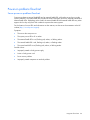
This guide provides common procedures and solutions for the many levels of troubleshooting a ProLiant
server—from the most basic connector issues to complex software configuration problems.
To understand the sections of this guide and to identify the best starting point for a problem, use the following
descriptions:
•
Common problem resolution (on page 18)
Many server problems are caused by loose connections, outdated firmware, and other issues. Use this
section to perform basic troubleshooting for common problems.
•
Diagnostic flowcharts (on page 22)
When a server exhibits symptoms that do not immediately pinpoint the problem, use this section to
begin troubleshooting. The section contains a series of flowcharts that provide a common
troubleshooting process for ProLiant servers. The flowcharts identify a diagnostic tool or a process to
help solve the problem.
•
Hardware problems (on page 37)
When the symptoms point to a specific component, use this section to find solutions for problems with
power, general components, system boards, system open circuits and short circuits, and external
devices.
•
Software problems (on page 60)
When you have a known, specific software problem, use this section to identify a solution to the
problem.
•
Software tools and solutions (on page 67)
Use this section as a reference for software tools and utilities.
•
HP resources for troubleshooting (on page 86)
Getting started 11
When additional information becomes necessary, use this section to identify websites and
supplemental documents that contain troubleshooting information.
•
Error messages (on page 91)
Use this section for a complete list of the following messages:
o
ADU error messages (on page 91)
o
POST error messages and beep codes (on page 121)
o
Event list error messages (on page 171)
o
HP BladeSystem infrastructure error codes ("HP BladeSystem p-Class infrastructure error codes" on
page 175)
o
Port 85 codes and iLO messages (on page 179)
Pre-diagnostic steps
WARNING: To avoid potential problems, ALWAYS read the warnings and cautionary
information in the server documentation before removing, replacing, reseating, or modifying
system components.
IMPORTANT: This guide provides information for multiple servers. Some information may not
apply to the server you are troubleshooting. Refer to the server documentation for information on
procedures, hardware options, software tools, and operating systems supported by the server.
1.
Review the important safety information (on page 12).
2.
Gather symptom information (on page 15).
3.
Prepare the server for diagnosis (on page 15).
4.
Use the Start diagnosis flowchart (on page 24) to begin the diagnostic process.
Important safety information
Familiarize yourself with the safety information in the following sections before troubleshooting the server.
Important safety information
Before servicing this product, read the Important Safety Information document provided with the server.
Symbols on equipment
The following symbols may be placed on equipment to indicate the presence of potentially hazardous
conditions.
This symbol indicates the presence of hazardous energy circuits or electric shock
hazards. Refer all servicing to qualified personnel.
WARNING: To reduce the risk of injury from electric shock hazards, do not open this
enclosure. Refer all maintenance, upgrades, and servicing to qualified personnel.
Getting started 12
This symbol indicates the presence of electric shock hazards. The area contains no user
or field serviceable parts. Do not open for any reason.
WARNING: To reduce the risk of injury from electric shock hazards, do not open this
enclosure.
This symbol on an RJ-45 receptacle indicates a network interface connection.
WARNING: To reduce the risk of electric shock, fire, or damage to the equipment, do
not plug telephone or telecommunications connectors into this receptacle.
This symbol indicates the presence of a hot surface or hot component. If this surface is
contacted, the potential for injury exists.
WARNING: To reduce the risk of injury from a hot component, allow the surface to cool
before touching.
weight in kg
weight in lb
This symbol indicates that the component exceeds the recommended weight for one
individual to handle safely.
WARNING: To reduce the risk of personal injury or damage to the equipment, observe
local occupational health and safety requirements and guidelines for manual material
handling.
These symbols, on power supplies or systems, indicate that the equipment is supplied
by multiple sources of power.
WARNING: To reduce the risk of injury from electric shock, remove all power cords to
completely disconnect power from the system.
Warnings and cautions
WARNING: Only authorized technicians trained by HP should attempt to repair this equipment.
All troubleshooting and repair procedures are detailed to allow only subassembly/module-level
repair. Because of the complexity of the individual boards and subassemblies, no one should
attempt to make repairs at the component level or to make modifications to any printed wiring
board. Improper repairs can create a safety hazard.
WARNING: To reduce the risk of personal injury or damage to the equipment, be sure that:
•
•
•
•
•
The leveling feet are extended to the floor.
The full weight of the rack rests on the leveling feet.
The stabilizing feet are attached to the rack if it is a single-rack installation.
The racks are coupled together in multiple-rack installations.
Only one component is extended at a time. A rack may become unstable if more than one
component is extended for any reason.
WARNING: To reduce the risk of electric shock or damage to the equipment:
• Do not disable the power cord grounding plug. The grounding plug is an important safety
feature.
• Plug the power cord into a grounded (earthed) electrical outlet that is easily accessible at all
times.
• Unplug the power cord from the power supply to disconnect power to the equipment.
• Do not route the power cord where it can be walked on or pinched by items placed against it.
Pay particular attention to the plug, electrical outlet, and the point where the cord extends from
the server.
Getting started 13
WARNING: To reduce the risk of personal injury or damage to the equipment:
weight in kg
weight in lb
• Observe local occupation health and safety requirements and guidelines for manual
handling.
• Obtain adequate assistance to lift and stabilize the chassis during installation or
removal.
• The server is unstable when not fastened to the rails.
• When mounting the server in a rack, remove the power supplies and any other
removable module to reduce the overall weight of the product.
CAUTION: To properly ventilate the system, you must provide at least 7.6 cm (3.0 in) of
clearance at the front and back of the server.
CAUTION: The server is designed to be electrically grounded (earthed). To ensure proper
operation, plug the AC power cord into a properly grounded AC outlet only.
Electrostatic discharge
Preventing electrostatic discharge
To prevent damaging the system, be aware of the precautions you need to follow when setting up the system
or handling parts. A discharge of static electricity from a finger or other conductor may damage system
boards or other static-sensitive devices. This type of damage may reduce the life expectancy of the device.
To prevent electrostatic damage:
•
Avoid hand contact by transporting and storing products in static-safe containers.
•
Keep electrostatic-sensitive parts in their containers until they arrive at static-free workstations.
•
Place parts on a grounded surface before removing them from their containers.
•
Avoid touching pins, leads, or circuitry.
•
Always be properly grounded when touching a static-sensitive component or assembly.
Grounding methods to prevent electrostatic discharge
Several methods are used for grounding. Use one or more of the following methods when handling or
installing electrostatic-sensitive parts:
•
Use a wrist strap connected by a ground cord to a grounded workstation or computer chassis. Wrist
straps are flexible straps with a minimum of 1 megohm ±10 percent resistance in the ground cords. To
provide proper ground, wear the strap snug against the skin.
•
Use heel straps, toe straps, or boot straps at standing workstations. Wear the straps on both feet when
standing on conductive floors or dissipating floor mats.
•
Use conductive field service tools.
•
Use a portable field service kit with a folding static-dissipating work mat.
If you do not have any of the suggested equipment for proper grounding, have an authorized reseller install
the part.
For more information on static electricity or assistance with product installation, contact an authorized
reseller.
Getting started 14
Symptom information
Before troubleshooting a server problem, collect the following information:
•
What events preceded the failure? After which steps does the problem occur?
•
What has been changed since the time the server was working?
•
Did you recently add or remove hardware or software? If so, did you remember to change the
appropriate settings in the server setup utility, if necessary?
•
How long has the server exhibited problem symptoms?
•
If the problem occurs randomly, what is the duration or frequency?
To answer these questions, the following information may be useful:
•
Run HP Insight Diagnostics (on page 75) and use the survey page to view the current configuration or
to compare it to previous configurations.
•
Refer to your hardware and software records for information.
•
Refer to server LEDs and their statuses.
Prepare the server for diagnosis
1.
Be sure the server is in the proper operating environment with adequate power, air conditioning, and
humidity control. For required environmental conditions, see the server documentation (on page 86).
2.
Record any error messages displayed by the system.
3.
Remove all diskettes, CD-ROMs, DVD-ROMs, and USB drive keys.
4.
Power down the server and peripheral devices if you will be diagnosing the server offline. If possible,
always perform an orderly shutdown:
a. Exit any applications.
b. Exit the operating system.
c.
Power down the server.
5.
Disconnect any peripheral devices not required for testing (any devices not necessary to power up the
server). Do not disconnect the printer if you want to use it to print error messages.
6.
Collect all tools and utilities, such as a Torx screwdriver, loopback adapters, ESD wrist strap, and
software utilities, necessary to troubleshoot the problem.
o
You must have the appropriate Health Drivers and Management Agents installed on the server.
To verify the server configuration, connect to the System Management Homepage
(http://h18013.www1.hp.com/products/servers/management/agents/index.html ) and select
Version Control Agent. The VCA gives you a list of names and versions of all installed HP drivers,
Management Agents, and utilities, and whether they are up-to-date.
o
HP recommends you have access to the server documentation (on page 86) for server-specific
information.
o
HP recommends you have access to the SmartStart CD for value-added software and drivers
required during the troubleshooting process. Download the current version of SmartStart from the
HP website (http://www.hp.com/servers/smartstart).
Getting started 15
Performing processor procedures in the troubleshooting process
Because this document supports multiple generations of HP ProLiant server models, it also covers processes
that include troubleshooting of various models and types of processors.
Before performing any troubleshooting steps that involve processors, review the following guidelines:
•
Be sure that only authorized personnel perform the troubleshooting steps that involve installation,
removal, or replacement of a processor.
•
Always locate the documentation for your processor model before performing any steps that require
installing, removing, or replacing a processor. If you cannot locate the hard copy of the instructions,
locate your server user guide or maintenance and service guide on the HP website
(http://www.hp.com/support/manuals).
•
Some processor models require the use of a processor installation tool, and specific steps are
documented to ensure that you do not damage the processor or processor socket on the system board.
For server models that have pins inside the processor socket, remember that THE PINS ON THE SYSTEM
BOARD ARE VERY FRAGILE AND EASILY DAMAGED. If you damage the socket, you must replace the
system board.
•
Depending on the server model, the contacts may be on the processor or they may be inside the
processor socket. Never touch the contacts. THE PINS ON THE SYSTEM BOARD ARE VERY FRAGILE AND
EASILY DAMAGED. If the contacts inside the processor socket are damaged, you must replace the
system board.
•
Always complete all other troubleshooting procedures before removing or replacing a processor.
Breaking the server down to the minimum hardware configuration
During the troubleshooting process, you may be asked to break the server down to the minimum hardware
configuration. A minimum configuration consists of only the components needed to boot the server and
successfully pass POST.
When requested to break the server down to the minimum configuration, uninstall the following components,
if installed:
•
All additional DIMMs
Leave only the minimum required to boot the server—either one DIMM or a pair of DIMMs. For more
information, see the memory guidelines in the server user guide.
•
All additional cooling fans, if applicable
For the minimum fan configuration, see the server user guide.
•
All additional power supplies, if applicable (leave one installed)
•
All hard drives
•
All optical drives (DVD-ROM, CD-ROM, and so forth)
•
All optional mezzanine cards
•
All expansion boards
Before removing the components, be sure to determine the minimum configuration for each component and
follow all guidelines in the server user guide.
Always use the recommended minimum configuration above before removing any processors. If you are
unable to isolate the issue with the configuration above, you will then remove all but one of the processors.
Getting started 16
CAUTION: Before removing or replacing any processors, be sure to follow the guidelines
provided in "Performing processor procedures in the troubleshooting process (on page 16)."
Failure to follow the recommended guidelines can cause damage to the system board, requiring
replacement of the system board.
Getting started 17
Common problem resolution
Loose connections
Action:
•
Be sure all power cords are securely connected.
•
Be sure all cables are properly aligned and securely connected for all external and internal
components.
•
Remove and check all data and power cables for damage. Be sure no cables have bent pins or
damaged connectors.
•
If a fixed cable tray is available for the server, be sure the cords and cables connected to the server are
routed correctly through the tray.
•
Be sure each device is properly seated. Avoid bending or flexing circuit boards when reseating
components.
•
If a device has latches, be sure they are completely closed and locked.
•
Check any interlock or interconnect LEDs that may indicate a component is not connected properly.
•
If problems continue to occur, remove and reinstall each device, checking the connectors and sockets
for bent pins or other damage.
•
For HP ProLiant BL c-Class Server Blades, be sure the Onboard Administrator tray is seated properly.
Service notifications
To view the latest service notifications, refer to the HP website (http://www.hp.com/go/bizsupport). Select
the appropriate server model, and then click the Troubleshoot a Problem link on the product page.
Firmware updates
Download firmware updates from the following locations:
•
The most recent SPP ("HP Service Pack for ProLiant" on page 78) from the HP website
(http://www.hp.com/go/spp).
•
The HP Smart Components available as part of the SPP ("HP Service Pack for ProLiant" on page 78).
•
The most recent version of a particular server or option firmware from the HP website
(http://www.hp.com/support).
All servers discussed in this document might not be supported by SPP. To determine if your product is
supported by the SPP, see the latest server support guide on the HP website
(http://www.hp.com/go/spp/documentation). If your server is not supported by SPP, see "Keeping the
system current (on page 77)" for other options.
Common problem resolution
18
HP offers a subscription service that can provide notification of firmware updates. For more information, see
"Subscriber's Choice (on page 80)."
For more information on updating firmware, see "Firmware maintenance (on page 80)."
DIMM handling guidelines
CAUTION: Failure to properly handle DIMMs can cause damage to DIMM components and the
system board connector.
When handling a DIMM, observe the following guidelines:
•
Avoid electrostatic discharge (on page 14).
•
Always hold DIMMs by the side edges only.
•
Avoid touching the connectors on the bottom of the DIMM.
•
Never wrap your fingers around a DIMM.
•
Avoid touching the components on the sides of the DIMM.
•
Never bend or flex the DIMM.
When installing a DIMM, observe the following guidelines:
•
Before seating the DIMM, align the DIMM with the slot.
•
To align and seat the DIMM, use two fingers to hold the DIMM along the side edges.
•
To seat the DIMM, use two fingers to apply gentle pressure along the top of the DIMM.
For more information, see the HP website
(http://h20000.www2.hp.com/bizsupport/TechSupport/Document.jsp?lang=en&cc=us&objectID=c008
68283&jumpid=reg_R1002_USEN).
Hard drive guidelines
SAS and SATA hard drive guidelines
When adding hard drives to the server, observe the following general guidelines:
•
The system automatically sets all drive numbers.
•
If only one hard drive is used, install it in the bay with the lowest drive number.
•
Drives must be the same capacity to provide the greatest storage space efficiency when drives are
grouped together into the same drive array.
•
Drives in the same logical volume must be of the same type:
o
ACU does not support mixing SAS and SATA drives in the same logical volume.
o
ACU does not support mixing traditional drives and solid state drives (SSD) in the same logical
volume.
SCSI hard drive guidelines
•
Each SCSI drive must have a unique ID.
Common problem resolution
19
•
The system automatically sets all SCSI IDs.
•
If only one SCSI hard drive is used, install it in the bay with the lowest number.
•
Drives must be the same capacity to provide the greatest storage space efficiency when drives are
grouped together into the same drive array.
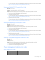
Hard drive LED combinations
Hot-plug SCSI hard drive LED combinations
Activity
LED (1)
Online
LED (2)
On, off, or On or off
flashing
On, off, or On
Fault LED Interpretation
(3)
Flashing
A predictive failure alert has been received for this drive.
Replace the drive as soon as possible.
Off
The drive is online and is configured as part of an array.
If the array is configured for fault tolerance and all other drives in the
array are online, and a predictive failure alert is received or a drive
capacity upgrade is in progress, you may replace the drive online.
flashing
On or
flashing
Flashing
Off
Do not remove the drive. Removing a drive may terminate the current
operation and cause data loss.
The drive is rebuilding or undergoing capacity expansion.
On
Off
Off
Do not remove the drive.
The drive is being accessed, but (1) it is not configured as part of an
array; (2) it is a replacement drive and rebuild has not yet started; or
(3) it is spinning up during the POST sequence.
Flashing
Flashing
Flashing
Do not remove the drive. Removing a drive may cause data loss in
non-fault-tolerant configurations.
One or more of the following conditions may exist:
•
•
•
The drive is part of an array being selected by an array
configuration utility
Drive Identification has been selected in HP SIM
The drive firmware is being updated
Off
Off
On
The drive has been placed offline due to hard disk drive failure or
subsystem communication failure.
You may need to replace the drive.
Off
Off
Off
One or more of the following conditions may exist:
•
•
•
The drive is not configured as part of an array
The drive is configured as part of an array, but it is a replacement
drive that is not being accessed or being rebuilt yet
The drive is configured as an online spare
If the drive is connected to an array controller, you may replace the
drive online.
SAS and SATA hard drive LED combinations
NOTE: Predictive failure alerts can occur only when the server is connected to a Smart Array
controller.
Common problem resolution
20
Online/activity
LED (green)
Fault/UID LED
(amber/blue)
Interpretation
On, off, or flashing Alternating amber
and blue
The drive has failed, or a predictive failure alert has been received
for this drive; it also has been selected by a management
application.
On, off, or flashing Steadily blue
The drive is operating normally, and it has been selected by a
management application.
On
Amber, flashing
regularly (1 Hz)
A predictive failure alert has been received for this drive.
Replace the drive as soon as possible.
On
Off
The drive is online, but it is not active currently.
Flashing regularly
(1 Hz)
Amber, flashing
regularly (1 Hz)
Do not remove the drive. Removing a drive may terminate the
current operation and cause data loss.
The drive is part of an array that is undergoing capacity expansion
or stripe migration, but a predictive failure alert has been received
for this drive. To minimize the risk of data loss, do not replace the
drive until the expansion or migration is complete.
Flashing regularly
(1 Hz)
Off
Do not remove the drive. Removing a drive may terminate the
current operation and cause data loss.
The drive is rebuilding, erasing, or it is part of an array that is
undergoing capacity expansion or stripe migration.
Flashing irregularly Amber, flashing
regularly (1 Hz)
The drive is active, but a predictive failure alert has been received
for this drive. Replace the drive as soon as possible.
Flashing irregularly Off
Steadily amber
Off
The drive is active, and it is operating normally.
A critical fault condition has been identified for this drive, and the
controller has placed it offline. Replace the drive as soon as
possible.
Off
Amber, flashing
regularly (1 Hz)
A predictive failure alert has been received for this drive. Replace
the drive as soon as possible.
Off
Off
The drive is offline, a spare, or not configured as part of an array.
Server updates with an HP Trusted Platform Module
and BitLocker™ enabled
When a TPM is installed and enabled in RBSU, and when the Microsoft® Windows® BitLocker™ Drive
Encryption feature is enabled, always disable BitLocker™ before performing any of the following
procedures:
•
Restarting the computer for maintenance without a PIN or startup key
•
Updating firmware (on page 82)
•
Upgrading critical early boot components
•
Upgrading the system board to replace or remove the TPM
•
Disabling or clearing the TPM
•
Moving a BitLocker™-protected drive to another server
•
Adding an optional PCI device, such as a storage controller or network adapter
Common problem resolution
21
Diagnostic flowcharts
Troubleshooting flowcharts
To effectively troubleshoot a problem, HP recommends that you start with the first flowchart in this section,
"Start diagnosis flowchart (on page 24)," and follow the appropriate diagnostic path. If the other flowcharts
do not provide a troubleshooting solution, follow the diagnostic steps in "General diagnosis flowchart (on
page 24)." The General diagnosis flowchart is a generic troubleshooting process to be used when the
problem is not server-specific or is not easily categorized into the other flowcharts.
The available flowcharts include:
•
Start diagnosis flowchart (on page 24)
•
General diagnosis flowchart (on page 24)
•
Power-on problems
•
o
Server power-on problems flowchart (on page 26)
o
p-Class server blade power-on problems flowchart (on page 28)
o
c-Class server blade power-on problems flowchart (on page 28)
POST problems flowchart (on page 30)
o
Server and p-Class server blade POST problems flowchart (on page 31)
o
c-Class server blade POST problems flowchart (on page 32)
•
Operating system boot problems flowchart (on page 32)
•
Server fault indications flowchart
o
Server and p-Class server blade fault indications flowchart (on page 34)
o
c-Class server blade fault indications flowchart (on page 36)
Troubleshooting flowchart reference websites
Each flowchart contains references to external websites. The following websites correspond to the numbered
websites in each flowchart:
1.
HP Technical Support (http://www.hp.com/support)
Select your country and then follow the instructions to locate software, firmware, and drivers.
2.
HP ProLiant maintenance and service guides:
o
Business Support Center (http://www.hp.com/go/bizsupport)
Select Manuals. Under Servers, select ProLiant and tc series servers. Select the product, and then
locate the link for the maintenance and service guide.
o
HP BladeSystem p-Class Support and Documents
(http://www.hp.com/products/servers/proliant-bl/p-class/info)
Under Product support, select the product. Select Manuals (guides, supplements, addendums, etc).
Under Service and maintenance information, locate the link for the maintenance and service guide.
Diagnostic flowcharts
22
o
HP BladeSystem c-Class Technical Documentation
(http://www.hp.com/go/bladesystem/documentation)
Select Support, Drivers and Manuals, and then select the product. Select Manuals, and then locate
the link for the maintenance and service guide.
3.
HP BladeSystem p-Class Support and Documents
(http://www.hp.com/products/servers/proliant-bl/p-class/info)
To locate the HP BladeSystem p-Class System Maintenance and Service Guide, select the product.
Select Manuals (guides, supplements, addendums, etc). Under Service and maintenance information,
locate the link for the document.
4.
HP BladeSystem Power Sizer (http://www.hp.com/go/bladesystem/powercalculator)
Use the Power Sizer to plan your power infrastructure and meet the needs of an HP BladeSystem
solution.
5.
Remote management (http://www.hp.com/servers/lights-out)
To locate the Integrated Lights-Out User Guide, select the product, and then select Support &
Documents. Select Manuals and locate the link to the document.
6.
SmartStart Support and Documents (http://www.hp.com/support/smartstart/documentation)
In the User guides section, locate the link for the HP ROM-Based Setup Utility User Guide.
7.
System Management Homepage (https://localhost:2381)
Access consolidated system management information.
Diagnostic flowcharts
23
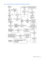
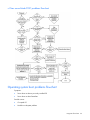
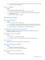
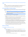
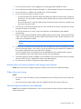
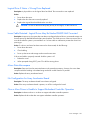
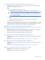
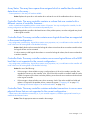
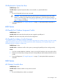
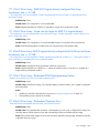
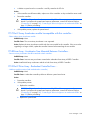
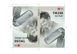
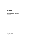
Start diagnosis flowchart
Use the following flowchart to start the diagnostic process.
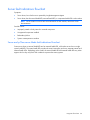
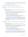
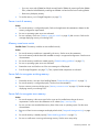
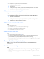
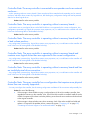
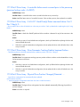
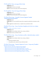
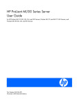
General diagnosis flowchart
Diagnostic flowcharts
24
The General diagnosis flowchart provides a generic approach to troubleshooting. If you are unsure of the
problem, or if the other flowcharts do not fix the problem, use the following flowchart.
Diagnostic flowcharts
25
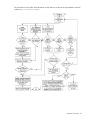
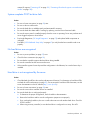
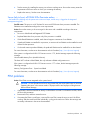
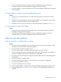
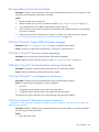
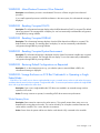
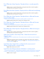
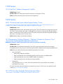
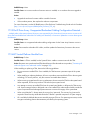
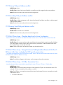
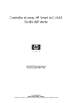
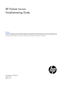
Power-on problems flowchart
Server power-on problems flowchart
Some servers have an internal health LED and an external health LED, while other servers have a single
system health LED. The system health LED provides the same functionality as the two separate internal and
external health LEDs. Depending on the model, the internal health LED and external health LED may either
appear solid or they may flash. Both conditions represent the same symptom.
For the location of server LEDs and information on their statuses, see the server documentation on the HP
website (http://www.hp.com/support).
Symptoms:
•
The server does not power on.
•
The system power LED is off or amber.
•
The external health LED is red, flashing red, amber, or flashing amber.
•
The internal health LED is red, flashing red, amber, or flashing amber.
•
The system health LED is red, flashing red, amber, or flashing amber.
Possible causes:
•
Improperly seated or faulty power supply
•
Loose or faulty power cord
•
Power source problem
•
Improperly seated component or interlock problem
Diagnostic flowcharts
26
Diagnostic flowcharts
27
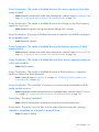
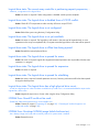
p-Class server blade power-on problems flowchart
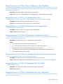
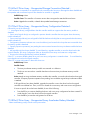
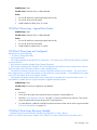
c-Class server blade power-on problems flowchart
For the location of server LEDs and information on their statuses, see the server documentation on the HP
website (http://www.hp.com/support).
Diagnostic flowcharts
28
Symptoms:
•
The server does not power on.
•
The system power LED is off or amber.
•
The health LED is red or amber.
Possible causes:
•
Improperly seated or faulty power supply
•
Loose or faulty power cord
•
Power source problem
•
Improperly seated component or interlock problem
Diagnostic flowcharts
29
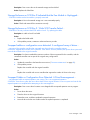
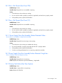
POST problems flowchart
Symptoms:
•
Server does not complete POST
NOTE: The server has completed POST when the system attempts to access the boot device.
•
Server completes POST with errors
Possible problems:
•
Improperly seated or faulty internal component
•
Faulty KVM device
•
Faulty video device
Diagnostic flowcharts
30
Server and p-Class server blade POST problems flowchart
Diagnostic flowcharts
31
c-Class server blade POST problems flowchart
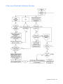
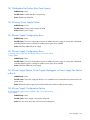
Operating system boot problems flowchart
Symptoms:
•
Server does not boot a previously installed OS
•
Server does not boot SmartStart
Possible causes:
•
Corrupted OS
•
Hard drive subsystem problem
Diagnostic flowcharts
32
•
Incorrect boot order setting in RBSU
There are two ways to use SmartStart when diagnosing OS boot problems on a server blade:
•
Use iLO to remotely attach virtual devices to mount the SmartStart CD onto the server blade.
•
Use a local I/O cable and drive to connect to the server blade, and then restart the server blade.
Diagnostic flowcharts
33
Server fault indications flowchart
Symptoms:
•
Server boots, but a fault event is reported by Insight Management Agents
•
Server boots, but the internal health LED, external health LED, or component health LED is red or amber
NOTE: For the location of server LEDs and information on their statuses, refer to the server
documentation.
Possible causes:
•
Improperly seated or faulty internal or external component
•
Unsupported component installed
•
Redundancy failure
•
System overtemperature condition
Server and p-Class server blade fault indications flowchart
Some servers have an internal health LED and an external health LED, while other servers have a single
system health LED. The system health LED provides the same functionality as the two separate internal and
external health LEDs. Depending on the model, the internal health LED and external health LED may either
appear solid or they may flash. Both conditions represent the same symptom.
Diagnostic flowcharts
34
For the location of server LEDs and information on their statuses, see the server documentation on the HP
website (http://www.hp.com/support).
Diagnostic flowcharts
35
c-Class server blade fault indications flowchart
Diagnostic flowcharts
36
Hardware problems
Procedures for all ProLiant servers
The procedures in this section are comprehensive and include steps about or references to hardware features
that may not be supported by the server you are troubleshooting.
CAUTION: Before removing or replacing any processors, be sure to follow the guidelines
provided in "Performing processor procedures in the troubleshooting process (on page 16)."
Failure to follow the recommended guidelines can cause damage to the system board, requiring
replacement of the system board.
Power problems
Power source problems
Action:
1.
Press the Power On/Standby button to be sure it is on. If the server has a Power On/Standby button that
returns to its original position after being pressed, be sure you press the switch firmly.
2.
Plug another device into the grounded power outlet to be sure the outlet works. Also, be sure the power
source meets applicable standards.
3.
Replace the power cord with a known functional power cord to be sure it is not faulty.
4.
Replace the power strip with a known functional power strip to be sure it is not faulty.
5.
Have a qualified electrician check the line voltage to be sure it meets the required specifications.
6.
Be sure the proper circuit breaker is in the On position.
7.
If Enclosure Dynamic Power Capping or Enclosure Power Limit is enabled on supported servers, be sure
there is sufficient power allocation to support the server. For more information, see the following
documents:
8.
o
The HP Power Capping and HP Dynamic Power Capping for ProLiant servers technology brief on
the HP website
(http://h20000.www2.hp.com/bc/docs/support/SupportManual/c01549455/c01549455.p
df)
o
The HP BladeSystem Onboard Administrator User Guide on the HP website
(http://www.hp.com/go/bladesystem/documentation)
Be sure no loose connections exist ("Loose connections" on page 18).
Power supply problems
Action:
1.
Be sure no loose connections exist ("Loose connections" on page 18).
Hardware problems
37
2.
If the power supplies have LEDs, be sure they indicate that each power supply is working properly. If
the LEDs indicate a problem with a power supply, replace the power supply. For more information, see
the server documentation on the HP website (http://www.hp.com/support).
3.
Be sure the system has enough power, particularly if you recently added hardware, such as hard drives.
Additional power supplies may be required. Check the system information from the IML.
For product-specific information, see the server documentation on the HP website
(http://www.hp.com/support).
For more information, see the HP Power Advisor on the HP website
(http://www.hp.com/go/hppoweradvisor).
4.
If running a redundant configuration, be sure that all of the power supplies in the system are the same.
For a list of supported power supplies, see the server documentation on the HP website
(http://www.hp.com/support).
System open circuits and short circuits
Action:
CAUTION: Do not operate the server for long periods with the access panel open or removed.
Operating the server in this manner results in improper airflow and improper cooling that can
lead to thermal damage.
1.
Check the server LEDs to see if any statuses indicate the source of the problem. For LED information,
refer to the server documentation.
2.
Remove all power sources to the server.
3.
Be sure no loose connections (on page 18) exist in the area.
4.
Be sure each component in the area is working. Refer to the section for each component in this guide.
If you cannot determine the problem by checking the specific area, perform each of the following actions.
Restart the server after each action to see if the problem has been corrected.
•
Reseat all I/O expansion boards.
•
Be sure no loose connections (on page 18) exist in the rest of the server, particularly with the cables that
connect to the system board.
•
Be sure no foreign material exists, such as screws, bits, or slot bracket blanks, that may be short
circuiting components.
UPS problems
UPS is not working properly
Action:
1.
Be sure the UPS batteries are charged to the proper level for operation. See the UPS documentation for
details.
2.
Be sure the UPS power switch is in the On position. See the UPS documentation for the location of the
switch.
3.
Be sure the UPS software is updated to the latest version. Use the Power Management software located
on the Power Management CD.
Hardware problems
38
4.
Be sure the power cord is the correct type for the UPS and the country in which the server is located. See
the UPS reference guide for specifications.
5.
Be sure the line cord is connected.
6.
Be sure each circuit breaker is in the On position, or replace the fuse if needed. If this occurs repeatedly,
contact an authorized service provider.
7.
Check the UPS LEDs to be sure a battery or site wiring problem has not occurred. See the UPS
documentation.
8.
If the UPS sleep mode is initiated, disable sleep mode for proper operation. The UPS sleep mode can
be turned off through the configuration mode on the front panel.
9.
Change the battery to be sure damage was not caused by excessive heat, particularly if a recent air
conditioning outage has occurred.
NOTE: The optimal operating temperature for UPS batteries is 25°C (77°F). For approximately
every 8°C to 10°C (16°F to 18°F) average increase in ambient temperature above the optimal
temperature, battery life is reduced by 50 percent.
Low battery warning is displayed
Action:
1.
Plug the UPS into an AC grounded outlet for at least 24 hours to charge the batteries, and then test the
batteries. Replace the batteries if necessary.
2.
Be sure the alarm is set appropriately by changing the amount of time given before a low battery
warning. Refer to the UPS documentation for instructions.
One or more LEDs on the UPS is red
Action: Refer to the UPS documentation for instructions regarding the specific LED to determine the cause of
the error.
General hardware problems
Problems with new hardware
Action:
1.
Be sure the hardware being installed is a supported option on the server. For information on supported
hardware, see the server documentation.
If necessary, remove unsupported hardware.
2.
To be sure the problem is not caused by a change to the hardware release, see the release notes
included with the hardware. If no documentation is available, see the HP support website
(http://www.hp.com/support).
3.
Be sure the new hardware is installed properly. To be sure all requirements are met, see the device,
server, and OS documentation.
Common problems include:
o
Incomplete population of a memory bank
o
Installation of a processor without a corresponding PPM
Hardware problems
39
o
Installation of a SCSI device without termination or without proper ID settings
o
Setting of an IDE device to Primary/Secondary when the other device is set to CS
o
Connection of the data cable, but not the power cable, of a new device
4.
Be sure no memory, I/O, or interrupt conflicts exist.
5.
Be sure no loose connections (on page 18) exist.
6.
Be sure all cables are connected to the correct locations and are the correct lengths. For more
information, see the server documentation.
7.
Be sure other components were not accidentally unseated during the installation of the new hardware
component.
8.
Be sure all necessary software updates, such as device drivers, ROM updates, and patches, are
installed and current, and the correct version for the hardware is installed. For example, if you are using
a Smart Array controller, you need the latest Smart Array Controller device driver. Uninstall any
incorrect drivers before installing the correct drivers.
If the "Unsupported processor detected" message is displayed, update the system ROM to support the
installed processor. For more information, see "Unsupported processor stepping with Intel® processors
(on page 85)."
9.
After installing or replacing boards or other options, run RBSU to be sure all system components
recognize the changes. If you do not run the utility, you may receive a POST error message indicating
a configuration error.
a. Check the settings in RBSU.
b. Save and exit the utility.
c.
Restart the server.
For more information on RBSU, see the HP ROM-Based Setup Utility User Guide on the Documentation
CD or the HP website (http://www.hp.com/support/smartstart/documentation).
10.
Be sure all switch settings are set correctly. For additional information about required switch settings,
see the labels located on the inside of the server access panel or the server documentation.
11.
Be sure all boards are properly installed in the server.
12.
To see if the utility recognizes and tests the device, run HP Insight Diagnostics (on page 75).
13.
Uninstall the new hardware.
Unknown problem
Action:
1.
Power down and disconnect power to the server.
2.
Following the guidelines and cautionary information in the server documentation, reduce the server to
the minimum hardware configuration by removing all cards or devices that are not necessary to start the
server. Keep the monitor connected to view the server startup process. Before completing this step, see
"Breaking the server down to the minimum hardware configuration (on page 16)."
3.
Reconnect power, and then power on the system.
o
If the video does not work, see "Video problems (on page 53)."
Hardware problems
40
CAUTION: Only authorized technicians trained by HP should attempt to remove the system
board. If you believe the system board requires replacement, contact HP Technical Support
("Contacting HP" on page 185, "Contacting HP technical support or an authorized reseller" on
page 185) before proceeding.
CAUTION: Before removing or replacing any processors, be sure to follow the guidelines
provided in "Performing processor procedures in the troubleshooting process (on page 16)."
Failure to follow the recommended guidelines can cause damage to the system board, requiring
replacement of the system board.
o
If the system fails in this minimum configuration, one of the primary components has failed. If you
have already verified that the processor, PPM, power supply, and memory are working before
getting to this point, replace the system board. If not, be sure each of those components is working.
o
If the system boots and video is working, add each component back to the server one at a time,
restarting the server after each component is added to determine if that component is the cause of
the problem. When adding each component back to the server, be sure to disconnect power to the
server and follow the guidelines and cautionary information in the server documentation.
Third-party device problems
Action:
1.
Refer to the server and operating system documentation to be sure the server and operating system
support the device.
2.
Be sure the latest device drivers ("Drivers" on page 77) are installed.
3.
Refer to the device documentation to be sure the device is properly installed. For example, a third-party
PCI or PCI-X board may be required to be installed on the primary PCI or PCI-X bus, respectively.
Testing the device
Action:
1.
Uninstall the device.
If the server works with the device removed and uninstalled, a problem exists with the device, the server
does not support the device, or a conflict exists with another device.
2.
If the device is the only device on a bus, be sure the bus works by installing a different device on the bus.
3.
Restarting the server each time to determine if the device is working, move the device:
a. To a different slot on the same bus (not applicable for PCI Express)
b. To a PCI, PCI-X, or PCI Express slot on a different bus
c.
To the same slot in another working server of the same or similar design
If the board works in any of these slots, either the original slot is bad or the board was not properly
seated. Reinsert the board into the original slot to verify.
4.
If you are testing a board (or a device that connects to a board):
a. Test the board with all other boards removed.
b. Test the server with only that board removed.
Hardware problems
41
CAUTION: Clearing NVRAM deletes the configuration information. Refer to the server
documentation for complete instructions before performing this operation or data loss could
occur.
5.
Clearing NVRAM can resolve various problems. Clear the NVRAM, but do not use the backup .SCI file
if prompted. Have available any .CFG, .OVL, or .PCF files that are required.
Internal system problems
Battery pack problems
The battery stops charging or begins to swell
The batteries in BBWC battery packs are a consumable material. After 3 years of service, batteries may not
provide predictable data retention times. If a battery fails completely, the HP Smart Array controller detects
this condition and automatically restricts write cache functions to protect user data. To help ensure
uninterrupted performance levels, HP recommends replacing battery packs at 3-year intervals.
In NiMH batteries, the charging and discharging processes create and recombine inert gases, which can
cause the button cell to swell in size by as much as 20%. Battery packs are designed to stop charging before
excess swelling occurs.
However, if excess swelling does occur, a pressure mechanism within the button cell releases these non-toxic,
non-corrosive gases before the cell incurs physical damage. If this pressure release occurs, the battery no
longer charges properly, and the storage solution reports a failed battery.
CD-ROM and DVD drive problems
System does not boot from the drive
Action:
1.
Be sure the drive boot order in RBSU is set so that the server boots from the CD-ROM drive first.
2.
If the CD-ROM drive jumpers are set to CS (the factory default), be sure the CD-ROM drive is installed
as device 0 on the cable so that it is in position for the server to boot from the drive.
3.
Be sure no loose connections (on page 18) exist.
4.
Be sure the media from which you are attempting to boot is not damaged and is a bootable CD.
5.
If attempting to boot from a USB CD-ROM drive:
o
Refer to the operating system and server documentation to be sure both support booting from a USB
CD-ROM drive.
o
Be sure legacy support for a USB CD-ROM drive is enabled in RBSU.
Data read from the drive is inconsistent, or drive cannot read data
Action:
1.
Clean the drive and media.
2.
If a paper or plastic label has been applied to the surface of the CD or DVD in use, remove the label and
any adhesive residue.
Hardware problems
42
3.
Be sure the inserted CD or DVD format is valid for the drive. For example, be sure you are not inserting
a DVD into a drive that only supports CDs.
Drive is not detected
Action:
1.
Be sure no loose connections (on page 18) exist.
2.
Refer to the drive documentation to be sure cables are connected as required.
3.
Be sure the cables are working properly. Replace with known functional cables to test whether the
original cables were faulty.
4.
Be sure the correct, current driver is installed.
Diskette drive problems
Diskette drive light stays on
Action:
1.
Be sure no loose connections (on page 18) exist.
2.
Be sure the diskette is not damaged. Run the diskette utility on the diskette (CHKDSK on some systems).
3.
Be sure the diskette is properly inserted. Remove the diskette and reinsert correctly into the drive.
4.
Be sure the diskette drive is cabled properly. Refer to the server documentation.
A problem has occurred with a diskette transaction
Action: Be sure the directory structure on the diskette is not bad. Run the diskette utility to check for
fragmentation (CHKDSK on some systems).
Diskette drive cannot read a diskette
Action:
1.
If the diskette is not formatted, format the diskette.
2.
Check the type of drive you are using and be sure you are using the correct diskette type.
Drive is not found
Action: Be sure no loose connections (on page 18) exist with the drive.
Non-system disk message is displayed
Action:
1.
Remove the non-system diskette from the drive.
2.
Check for and disconnect any non-bootable USB devices.
Diskette drive cannot write to a diskette
Action:
1.
If the diskette is not formatted, format the diskette.
Hardware problems
43
2.
Be sure the diskette is not write protected. If it is, use another diskette or remove the write protection.
3.
Be sure you are attempting to write to the proper drive by checking the drive letter in the path statement.
4.
Be sure enough space is available on the diskette.
Drive problems (hard drives and solid state drives)
HP SIM reports a drive fault on a hard drive managed by an HP Smart Array
controller
Action:
•
If the drive fault LED is illuminated, see the drive LED combination tables in "Hard drive LED
combinations (on page 20)."
•
If the drive fault LED is flashing, replace the hard drive. See the server maintenance and service guide.
•
If the drive fault LED is not flashing and the operating system supports HP Insight Diagnostics, version
7.40 or later ("HP Insight Diagnostics" on page 75), perform the following:
a. Run the Smart Array SCSI Diagnosis feature (on page 75).
b. Perform the actions recommended by the diagnosis report.
c.
If the issue is still present, run the appropriate array diagnostic software (on page 76).
For array diagnostic software report analysis, contact HP support ("Contacting HP" on page 185,
"Contacting HP technical support or an authorized reseller" on page 185).
•
If the drive fault LED is not flashing and the operating system does not support HP Insight Diagnostics,
version 7.40 or later ("HP Insight Diagnostics" on page 75), insert the SmartStart CD and run the
appropriate array diagnostic software (on page 76). For array diagnostic software report analysis,
contact HP support ("Contacting HP" on page 185, "Contacting HP technical support or an authorized
reseller" on page 185).
The fault LED is illuminated on a hard drive managed by an HP Smart Array controller
Action:
•
If the drive fault LED is illuminated, see the drive LED combination tables in "Hard drive LED
combinations (on page 20)."
•
If the drive fault LED is flashing, replace the hard drive. See the server maintenance and service guide.
•
If the drive fault LED is not flashing and the operating system supports HP Insight Diagnostics, version
7.40 or later ("HP Insight Diagnostics" on page 75), perform the following:
a. Run the Smart Array SCSI Diagnosis feature (on page 75).
b. Perform the actions recommended by the diagnosis report.
c.
If the issue is still present, run the appropriate array diagnostic software (on page 76).
For array diagnostic software report analysis, contact HP support ("Contacting HP" on page 185,
"Contacting HP technical support or an authorized reseller" on page 185).
•
If the drive fault LED is not flashing and the operating system does not support HP Insight Diagnostics,
version 7.40 or later ("HP Insight Diagnostics" on page 75), insert the SmartStart CD and run the
appropriate array diagnostic software (on page 76). For array diagnostic software report analysis,
Hardware problems
44
contact HP support ("Contacting HP" on page 185, "Contacting HP technical support or an authorized
reseller" on page 185).
System completes POST but drive fails
Action:
1.
Be sure no loose connections (on page 18) exist.
2.
Be sure no device conflict exists.
3.
Be sure the hard drive is cabled properly and terminated if necessary.
4.
Be sure the hard drive data cable is working by replacing it with a known functional cable.
5.
Be sure the access panel is installed properly when the server is operating. Drives may overheat and
cause sluggish response or drive failure.
6.
Run Insight Diagnostics ("HP Insight Diagnostics" on page 75) and replace failed components as
indicated.
7.
Run RBSU ("HP ROM-Based Setup Utility" on page 67) to verify that the boot controller order is set
properly.
No hard drives are recognized
Action:
1.
Be sure no power problems (on page 37) exist.
2.
Check for loose connections (on page 18).
3.
Be sure that the controller supports the hard drives being installed.
4.
Be sure the controller has the most recent firmware.
5.
If the controller supports license keys and the configuration is dual domain, be sure the license key is
installed.
Hard drive is not recognized by the server
Action:
1.
Check the hard drive LEDs to be sure they indicate normal function. For information on hard drive LEDs,
see hard drive LED combinations (on page 20). For server-specific hard drive LED information, see the
server documentation or the HP website (http://www.hp.com).
2.
Be sure no loose connections (on page 18) exist.
3.
Be sure the correct drive controller drivers are installed.
4.
Be sure the hard drive is configured properly:
a. To determine the proper configuration, see the hard drive documentation.
b. Remove the hard drive and be sure the configuration jumpers are set properly.
c.
For a non-hot-plug hard drive, be sure a conflict does not exist with another hard drive. Check for
SCSI ID conflicts.
d. When using an array controller, be sure the hard drive is configured in an array. Run ACU.
Hardware problems
45
A new drive is not recognized
Action:
1.
Be sure the drive is supported. To determine drive support, see the server documentation or the HP
website (http://www.hp.com/go/bizsupport).
2.
Be sure the drive bay is not defective by installing the hard drive in another bay.
3.
Run HP Insight Diagnostics (on page 75). Then, replace failed components as indicated.
4.
When the drive is a replacement drive on an array controller, be sure that the drive is the same type and
of the same or larger capacity than the original drive.
Data is inaccessible
Action:
1.
Be sure the files are not corrupt. Run the repair utility for the operating system.
2.
Be sure no viruses exist on the server. Run a current version of a virus scan utility.
3.
When a TPM is installed and is being used with BitLocker™, be sure the TPM is enabled in RBSU ("HP
ROM-Based Setup Utility" on page 67). See the TPM replacement recovery procedure in the operating
system documentation.
4.
When migrating encrypted data to a new server, be sure to follow the recovery procedures in the
operating system documentation.
Server response time is slower than usual
Action:
1.
Be sure the hard drive is not full. If needed, increase the amount of free space on the hard drive. HP
recommends that hard drives have a minimum of 15 percent free space.
2.
Review information about the operating system encryption technology, which can cause a decrease in
server performance. For more information, see the operating system documentation.
SD card problems
System does not boot from the drive
Action:
1.
Be sure the drive boot order in RBSU is set so that the server boots from the SD card.
2.
Reseat the SD card.
USB drive key problems
System does not boot from the drive
Action:
1.
Be sure that USB is enabled in RBSU.
2.
Be sure the drive boot order in RBSU is set so that the server boots from the USB drive key.
3.
Reseat the USB drive key.
Hardware problems
46
Fan problems
General fan problems are occurring
Action:
1.
Be sure the fans are properly seated and working.
a. Follow the procedures and warnings in the server documentation for removing the access panels
and accessing and replacing fans.
b. Unseat, and then reseat, each fan according to the proper procedures.
c.
Replace the access panels, and then attempt to restart the server.
2.
Be sure the fan configuration meets the functional requirements of the server. Refer to the server
documentation.
3.
Be sure no ventilation problems exist. If you have been operating the server for an extended period of
time with the access panel removed, airflow may have been impeded, causing thermal damage to
components. Refer to the server documentation for further requirements.
4.
Be sure no POST error messages ("POST error messages and beep codes" on page 121) are displayed
while booting the server that indicate temperature violation or fan failure information. Refer to the server
documentation for the temperature requirements for the server.
5.
Access the IML to see if any event list error messages (on page 171) relating to fans are listed.
6.
Replace any required non-functioning fans and restart the server. Refer to the server documentation for
specifications on fan requirements.
7.
Be sure all fan slots have fans or blanks installed. Refer to the server documentation for requirements.
8.
Verify the fan airflow path is not blocked by cables or other material.
Hot-plug fan problems are occurring
Action:
1.
Check the LEDs to be sure the hot-plug fans are working. Refer to the server documentation for LED
information.
NOTE: For servers with redundant fans, backup fans may spin up periodically to test
functionality. This is part of normal redundant fan operation.
2.
Be sure no POST error messages ("POST error messages and beep codes" on page 121) are displayed.
3.
Be sure hot-plug fan requirements are being met. Refer to the server documentation.
All fans in an HP BladeSystem c-Class enclosure are operating at a high speed
...while fans in the other enclosures are operating at normal speed.
Action:
If all fan LEDs are solid green, but the fans in this enclosure are operating at a higher speed than normal, then
access more information from the Onboard Administrator or iLO 3.
Hardware problems
47
All fans in an HP ProLiant G6 server are not spinning or are not spinning at the same
speed
Action:
For all servers, access the IML. If no error messages are listed, then the fans are operating as designed. If an
error message is listed in the IML, then perform the suggested procedure to correct the error.
For all server blades, access more information from the Onboard Administrator or iLO 3.
HP Trusted Platform Module problems
Action: If the TPM fails and is no longer detected by RBSU, request a new system board and TPM board from
an HP authorized service provider ("Contacting HP technical support or an authorized reseller" on page
185).
CAUTION: Any attempt to remove an installed TPM from the system board breaks or disfigures
the TPM security rivet. Upon locating a broken or disfigured rivet on an installed TPM,
administrators should consider the system compromised and take appropriate measures to ensure
the integrity of the system data.
When installing or replacing a TPM, observe the following guidelines:
•
Do not remove an installed TPM. Once installed, the TPM becomes a permanent part of the system
board.
•
When installing or replacing hardware, HP service providers cannot enable the TPM or the encryption
technology. For security reasons, only the customer can enable these features.
•
When returning a system board for service replacement, do not remove the TPM from the system board.
When requested, HP Service provides a TPM with the spare system board.
•
Any attempt to remove an installed TPM from the system board breaks or disfigures the TPM security
rivet. Upon locating a broken or disfigured rivet on an installed TPM, administrators should consider the
system compromised and take appropriate measures to ensure the integrity of the system data.
•
When using BitLocker™, always retain the recovery key/password. The recovery key/password is
required to enter Recovery Mode after BitLocker™ detects a possible compromise of system integrity.
•
HP is not liable for blocked data access caused by improper TPM use. For operating instructions, see the
encryption technology feature documentation provided by the operating system.
Memory problems
General memory problems are occurring
Action:
•
Isolate and minimize the memory configuration. Use care when handling DIMMs ("DIMM handling
guidelines" on page 19).
o
Be sure the memory meets the server requirements and is installed as required by the server. Some
servers may require that memory banks be populated fully or that all memory within a memory bank
must be the same size, type, and speed. To determine if the memory is installed properly, see the
server documentation.
o
Check any server LEDs that correspond to memory slots.
Hardware problems
48
•
o
If you are unsure which DIMM has failed, test each bank of DIMMs by removing all other DIMMs.
Then, isolate the failed DIMM by switching each DIMM in a bank with a known working DIMM.
o
Remove any third-party memory.
To test the memory, run HP Insight Diagnostics (on page 75).
Server is out of memory
Action:
1.
Be sure the memory is configured properly. Refer to the application documentation to determine the
memory configuration requirements.
2.
Be sure no operating system errors are indicated.
3.
Be sure a memory count error ("Memory count error exists" on page 49) did not occur. Refer to the
message displaying memory count during POST.
Memory count error exists
Possible Cause: The memory modules are not installed correctly.
Action:
1.
Be sure the memory modules are supported by the server. See the server documentation.
2.
Be sure the memory modules have been installed correctly in a supported configuration. See the server
documentation.
3.
Be sure the memory modules are seated properly ("DIMM handling guidelines" on page 19).
4.
Be sure no operating system errors are indicated.
5.
Restart the server and check to see if the error message is still displayed.
6.
Run HP Insight Diagnostics (on page 75). Then, replace failed components as indicated.
Server fails to recognize existing memory
Action:
1.
Reseat the memory. Use care when handling DIMMs ("DIMM handling guidelines" on page 19).
2.
Be sure the memory is configured properly. See the server documentation.
3.
Be sure a memory count error did not occur ("Memory count error exists" on page 49). See the message
displaying memory count during POST.
Server fails to recognize new memory
Action:
1.
Be sure the memory is the correct type for the server and is installed according to the server
requirements. See the server documentation or HP website (http://www.hp.com).
2.
Be sure you have not exceeded the memory limits of the server or operating system. See the server
documentation.
3.
Be sure no Event List error messages are displayed in the IML ("Integrated Management Log" on page
76).
4.
Be sure the memory is seated properly ("DIMM handling guidelines" on page 19).
5.
Be sure no conflicts are occurring with existing memory. Run the server setup utility.
Hardware problems
49
6.
Test the memory by installing the memory into a known working server. Be sure the memory meets the
requirements of the new server on which you are testing the memory.
7.
Replace the memory. See the server documentation.
Server fails to boot, all DIMM LEDs illuminate amber, ....
...the health LED is blinking red, the system emits continuous beeps, and an entry is logged to the Integrated
Management Log (IML)
Possible cause: The server is an HP ProLiant G6 server with 5500-series Xeon processors installed. The
DIMMs are not installed according to the server requirements.
Action: Be sure the memory is the correct type for the server and is installed according to the server
requirements.
•
Do not mix Unbuffered and Registered PC3 DIMMs.
•
Populate DIMM slots for a processor only if the processor is installed.
•
If Unbuffered DIMMs are installed, each channel supports a maximum of two DIMMs.
•
If quad-rank DIMMs are installed for a processor, a maximum of two DIMMs can be installed on each
channel for that processor.
•
If a channel contains quad-rank DIMMs, the quad-rank DIMM must be installed first on that channel.
For more information, see the server documentation on the HP website (http://www.hp.com/support).
If the system is configured with HP iLO 2 Firmware version 1.75, the IML message reports the following
message:
Uncorrectable Memory Error (Module Unknown)
This does NOT indicate a failed DIMM; this only indicates a DIMM configuration error.
If the system is configured with HP iLO 2 Firmware version 1.77 or later, the IML message reports the
following message:
Memory Configuration Error: System boot halted
For more information, see the server documentation on the HP website (http://www.hp.com/support).
PPM problems
Action: If the PPMs are not integrated on the system board:
CAUTION: Do not operate the server for long periods with the access panel open or removed.
Operating the server in this manner results in improper airflow and improper cooling that can
lead to thermal damage.
1.
If applicable, check the PPM LEDs to identify if a PPM failure occurred. For information on LEDs, refer to
the server documentation.
2.
Reseat each PPM, and then restart the server.
3.
If reseating the PPMs is not effective, remove all but one PPM, restart the server to see if the PPM is
working, and then install each PPM individually, cycling power each time. Follow the warnings and
cautionary information in the server documentation.
Hardware problems
50
Processor problems
Action:
1.
If applicable, check the processor LEDs to identify if a PPM failure occurred. For LED information, see the
server documentation.
2.
Be sure each processor is supported by the server and is installed properly. For processor requirements,
see the server documentation.
3.
Be sure the server ROM is current.
If an "unsupported processor detected" message appears, see "Unsupported processor stepping with
Intel® processors (on page 85)."
4.
Be sure you are not mixing processor stepping, core speeds, or cache sizes if this is not supported on
the server. For more information, see the server documentation.
CAUTION: Removal of some processors and heatsinks require special considerations for
replacement, while other processors and heatsinks are integrated and cannot be reused once
separated. For specific instructions for the server you are troubleshooting, refer to processor
information in the server user guide.
CAUTION: Before removing or replacing any processors, be sure to follow the guidelines
provided in "Performing processor procedures in the troubleshooting process (on page 16)."
Failure to follow the recommended guidelines can cause damage to the system board, requiring
replacement of the system board.
5.
If the server has only one processor installed, replace it with a known functional processor. If the
problem is resolved after you restart the server, the original processor failed.
CAUTION: Before removing or replacing any processors, be sure to follow the guidelines
provided in "Performing processor procedures in the troubleshooting process (on page 16)."
Failure to follow the recommended guidelines can cause damage to the system board, requiring
replacement of the system board.
6.
If the server has multiple processors installed, test each processor:
a. Remove all but one processor from the server. Replace each with a processor terminator board or
blank, if applicable to the server.
b. If the server includes PPMs that are not integrated on the system board, remove all PPMs from the
server except for the PPM associated with the remaining processor.
c.
Replace the remaining processor with a known functional processor. If the problem is resolved after
you restart the server, a fault exists with one or more of the original processors. Install each
processor and its associated PPM (if applicable) one by one, restarting each time, to find the faulty
processor or processors. At each step, be sure the server supports the processor configurations.
Tape drive problems
The following sections include the most common tape drive issues. Actions are listed in the order that they
should be tried. If the issue is resolved, it is not necessary to complete the remaining actions.
All actions may not apply to all tape drives.
For detailed tape drive guided troubleshooting information, see the HP website
(http://www.hp.com/support/gts).
Hardware problems
51
To download HP StorageWorks Library and Tape Tools, see the HP website
(http://www.hp.com/support/tapetools).
For more information about common tasks, see the HP website (http://www.hp.com/support/lttfaq).
Stuck tape issue
Action:
1.
Manually press the Eject button. Allow up to 10 minutes for the tape to rewind and eject.
2.
Perform a forced eject:
a. Press and hold the Eject button for at least 10 seconds.
b. Allow up to 10 minutes for the tape to rewind and eject. The green Ready LED should flash.
3.
Power cycle the drive. Allow up to 10 minutes for the drive to become ready again.
4.
Check for conflicts in backup software services.
5.
Check the SCSI/HBA/Driver configuration of the drive.
6.
Inspect media and cables, and discard any that are faulty or damaged.
7.
Contact HP support ("Contacting HP technical support or an authorized reseller" on page 185).
Read/write issue
Action:
1.
Run the Drive Assessment Test in HP StorageWorks Library and Tape Tools.
CAUTION: Running the Drive Assessment Test overwrites the tape. If it is not possible to overwrite
the tape, run the logs-based Device Analysis Test instead.
2.
Run the Media Assessment Test in HP StorageWorks Library and Tape Tools. This is a read-only test.
Backup issue
Action:
1.
Run the Drive Assessment Test in HP StorageWorks Library and Tape Tools.
CAUTION: Running the Drive Assessment Test overwrites the tape. If it is not possible to overwrite
the tape, run the logs-based Device Analysis Test instead.
2.
Check the backup logs.
3.
Verify that a supported configuration is being used.
4.
Check for media damage:
5.
o
Incorrect label placement
o
Broken, missing, or loose leader pin
o
Damaged cartridge seam
o
Usage in incorrect environment
Check for software issues:
a. Check the backup software.
b. Check that virus scanning software is not scheduled to run at the same time as the back-up.
6.
Verify that a tape can be formatted.
Hardware problems
52
Media issue
Action:
1.
Verify that the correct media part number is being used.
2.
Pull a support ticket using HP StorageWorks Library and Tape Tools.
o
Look for issues in the cartridge health section.
o
Look for issues in the drive health section.
3.
Run the Media Assessment Test in HP StorageWorks Library and Tape Tools.
4.
Check for media damage:
5.
o
Incorrect label placement
o
Broken, missing, or loose leader pin
o
Damaged cartridge seam
o
Usage in incorrect environment
Check if the Tape Error LED is flashing:
a. Reload the suspect tape. If the Tape Error LED stops flashing, the problem has cleared.
b. Load a new or known good tape. If the Tape Error LED stops flashing, the problem has cleared.
c.
6.
Reload the suspect tape. If the Tape Error LED flashes, discard the suspect media as faulty.
Discard any media that has been used at temperatures greater than 45°C (113ºF) or less than 5ºC
(41ºF).
Graphics and video adapter problems
General graphics and video adapter problems are occurring
Action:
•
Use only cards listed as a supported option for the server. For a complete list of supported options, see
the server documentation on the HP website (http://www.hp.com/go/hpsc).
•
Be sure that the power supplies installed in the server provide adequate power to support the server
configuration. Some high-power graphics adapters require specific cabling, fans, or auxiliary power.
For more information about adapter power requirements, see the documentation that ships with the
graphics option or see the vendor website. For more information about server power capabilities, see
the server documentation on the HP website (http://www.hp.com/go/hpsc).
•
Be sure the adapter is seated properly.
External device problems
Video problems
Screen is blank for more than 60 seconds after you power up the server
Action:
Hardware problems
53
1.
Be sure the monitor power cord is plugged into a working grounded (earthed) AC outlet.
2.
Power up the monitor and be sure the monitor light is on, indicating that the monitor is receiving power.
3.
Be sure the monitor is cabled to the intended server or KVM connection.
4.
Be sure no loose connections (on page 18) exist.
o
For rack-mounted servers, check the cables to the KVM switch and be sure the switch is correctly set
for the server. You may need to connect the monitor directly to the server to be sure the KVM switch
has not failed.
o
For tower model servers, check the cable connection from the monitor to the server, and then from
the server to the power outlet.
5.
Press any key, or enter the password, and wait a few moments for the screen to activate to be sure the
energy saver feature is not in effect.
6.
Be sure the video driver is current. For driver requirements, see the third-party video adapter
documentation.
7.
Be sure a video expansion board has not been added to replace onboard video, making it seem like the
video is not working. Disconnect the video cable from the onboard video, and then reconnect it to the
video jack on the expansion board.
NOTE: All servers automatically bypass onboard video when a video expansion board is
present.
8.
Press any key, or enter the password, and wait a few moments for the screen to activate to be sure the
power-on password feature is not in effect. You can also tell if the power-on password is enabled if a
key symbol is displayed on the screen when POST completes.
If you do not have access to the password, you must disable the power-on password by using the
Password Disable switch on the system board. See the server documentation.
9.
If the video expansion board is installed in a PCI hot-plug slot, be sure the slot has power by checking
the power LED on the slot, if applicable. See the server documentation.
10.
Be sure the server and the OS support the video expansion board.
Monitor does not function properly with energy saver features
Action: Be sure the monitor supports energy saver features, and if it does not, disable the features.
Video colors are wrong
Action:
•
Be sure the 15-pin VGA cable is securely connected to the correct VGA port on the server and to the
monitor.
•
Be sure the monitor and any KVM switch are compatible with the VGA output of the server.
Slow-moving horizontal lines are displayed
Action: Be sure magnetic field interference is not occurring. Move the monitor away from other monitors or
power transformers.
Hardware problems
54
Mouse and keyboard problems
Action:
1.
Be sure no loose connections (on page 18) exist. If a KVM switching device is in use, be sure the server
is properly connected to the switch.
o
For rack-mounted servers, check the cables to the switch box and be sure the switch is correctly set
for the server.
o
For tower model servers, check the cable connection from the input device to the server.
2.
If a KVM switching device is in use, be sure all cables and connectors are the proper length and are
supported by the switch. Refer to the switch documentation.
3.
Be sure the current drivers for the operating system are installed.
4.
Be sure the device driver is not corrupted by replacing the driver.
5.
Restart the system and check whether the input device functions correctly after the server restarts.
6.
Replace the device with a known working equivalent device (another similar mouse or keyboard).
o
If the problem still occurs with the new mouse or keyboard, the connector port on the system I/O
board is defective. Replace the board.
o
If the problem no longer occurs, the original input device is defective. Replace the device.
7.
Be sure the keyboard or mouse is connected to the correct port. Determine whether the keyboard lights
flash at POST or the NumLock LED illuminates. If not, change port connections.
8.
Be sure the keyboard or mouse is clean.
Audio problems
Action: Be sure the server speaker is connected. Refer to the server documentation.
Printer problems
Printer does not print
Action:
1.
Be sure the printer is powered up and online.
2.
Be sure no loose connections (on page 18) exist.
3.
Be sure the correct printer drivers are installed.
Printer output is garbled
Action: Be sure the correct printer drivers are installed.
Hardware problems
55
Cable problems
Drive errors, retries, timeouts, and unwarranted drive failures when using an older
Mini SAS cable
Action: The Mini SAS connector life expectancy is 250 connect/disconnect cycles (for external, internal, and
cable Mini SAS connectors). If using an older cable that could be near the life expectancy, replace the Mini
SAS cable.
Local I/O cable problems
NOTE: The local I/O cable is used only with HP ProLiant p-Class server blades.
Action: If the local I/O cable does not have hot-plug functionality, be sure you are not using a PS/2 keyboard
or mouse. With a PS/2 keyboard or mouse, the local I/O cable cannot be connected as a hot-plug device.
Connect the local I/O cable before booting the server, or switch to USB devices (if supported) to use the local
I/O cable hot-plug functionality.
Modem problems
No dial tone exists
Action:
1.
Be sure the cables are plugged in as specified in the modem documentation.
2.
Connect a working telephone directly to the wall jack, and then test the line for a dial tone.
3.
If no dial tone is detected, the phone line is not working. Contact the local telephone company and
arrange to correct the problem.
No response occurs when you type AT commands
Action: Reconfigure the COM port address for the modem.
1.
Be sure the communications software is set to the COM port to which the modem is connected.
2.
Check IRQ settings in the software and on the modem to be sure no conflict exists.
3.
Type AT&F at the command prompt to reset the modem to factory-default settings.
4.
Be sure you are in terminal mode and not MS-DOS mode.
5.
Refer to the HP website (http://www.hp.com) for a complete list of AT commands.
AT commands are not visible
Action: Set the echo command to On using the AT command ATE.
Data is displayed as garbled characters after the connection is established
Action:
1.
Be sure both modems have the same settings, including speed, data, parity, and stop bits.
Hardware problems
56
2.
Be sure the software is set for the correct terminal emulation.
a. Reconfigure the software correctly.
b. Restart the server.
c.
Run the communications software, checking settings and making corrections where needed.
d. Restart the server, and then reestablish the modem connection.
Modem does not answer an incoming call
Action:
1.
Enable the auto-answer option in the communications software.
2.
Be sure an answering machine is not answering the line before the modem is able to answer.
a. Turn off the answering machine.
or
Reconfigure the auto-answer option to respond in fewer rings than the answering machine.
b. Restart the server, and then reattempt the connection.
Modem does not connect to another modem
Action:
1.
Be sure a dial tone exists.
2.
Be sure the line is not in use at another extension before using it.
3.
Be sure you are dialing the correct telephone number.
4.
Be sure the modem on the other end is working.
Modem disconnects while online
Action:
1.
Be sure no loose connections (on page 18) exist.
2.
Be sure no line interference exists. Retry the connection by dialing the number several times. If
conditions remain poor, contact the telephone company to have the line tested.
3.
Be sure an incoming call is not breaking the connection due to call waiting. Disable call waiting, and
then reestablish the connection.
AT command initialization string is not working
Action: Use the most basic string possible to perform the task. The default initialization string is
AT&F&C1&D2&K3.
Connection errors are occurring
Action:
1.
Check the maximum baud rate for the modem to which you are connecting, and then change the baud
rate to match.
2.
If the line you are accessing requires error control to be turned off, do so using the AT command
AT&Q6%C0.
Hardware problems
57
3.
Be sure no line interference exists. Retry the connection by dialing the number several times. If
conditions remain poor, contact the telephone company to have the line tested.
4.
Be sure the modem is current and compliant with CCITT and Bell standards. Replace with a supported
modem if needed.
You are unable to connect to an online subscription service
Action:
1.
If the line you are accessing requires error control to be turned off, do so using the AT command
AT&Q6%C0.
2.
If the ISP you are accessing requires access at a decreased baud rate, reconfigure the communications
software to correct the connection baud rate to match the ISP.
3.
If this does not work, force a slower baud rate (14400 baud) with the AT command AT&Q6N0S37=11.
You are unable to connect at 56 Kbps
Action:
1.
Find out the maximum baud rate at which the ISP connects, and change the settings to reflect this.
Reattempt to connect at a lower baud rate.
2.
Be sure no line interference exists. Retry the connection by dialing the number several times. If
conditions remain poor, contact the telephone company to have the line tested.
Network controller problems
Network controller is installed but not working
Action:
1.
Check the network controller LEDs to see if any statuses indicate the source of the problem. For LED
information, refer to the network controller documentation.
2.
Be sure no loose connections (on page 18) exist.
3.
Be sure the network cable is working by replacing it with a known functional cable.
4.
Be sure a software problem has not caused the failure. Refer to the operating system documentation for
guidelines on adding or replacing PCI Hot Plug devices, if applicable.
5.
Be sure the server and operating system support the controller. Refer to the server and operating system
documentation.
6.
Be sure the controller is enabled in RBSU.
7.
Check the PCI Hot Plug power LED to be sure the PCI slot is receiving power, if applicable.
8.
Be sure the server ROM is up to date.
9.
Be sure the controller drivers are up to date.
10.
Be sure a valid IP address is assigned to the controller and that the configuration settings are correct.
11.
Run Insight Diagnostics ("HP Insight Diagnostics" on page 75) and replace failed components as
indicated.
Hardware problems
58
Network controller has stopped working
Action:
1.
Check the network controller LEDs to see if any statuses indicate the source of the problem. For LED
information, refer to the network controller documentation.
2.
Be sure the correct network driver is installed for the controller and that the driver file is not corrupted.
Reinstall the driver.
3.
Be sure no loose connections (on page 18) exist.
4.
Be sure the network cable is working by replacing it with a known functional cable.
5.
Check the PCI Hot Plug power LED to be sure the PCI slot is receiving power, if applicable.
6.
Be sure the network controller is not damaged.
7.
Run Insight Diagnostics ("HP Insight Diagnostics" on page 75) and replace failed components as
indicated.
Network controller stopped working when an expansion board was added
Action:
1.
Be sure no loose connections (on page 18) exist.
2.
Be sure the server and operating system support the controller. Refer to the server and operating system
documentation.
3.
Be sure the new expansion board has not changed the server configuration, requiring reinstallation of
the network driver.
a. Uninstall the network controller driver for the malfunctioning controller in the operating system.
b. Restart the server and run RBSU. Be sure the server recognizes the controller and that resources are
available for the controller.
c.
Restart the server, and then reinstall the network driver.
4.
Refer to the operating system documentation to be sure the correct drivers are installed.
5.
Refer to the operating system documentation to be sure that the driver parameters match the
configuration of the network controller.
Problems are occurring with the network interconnect blades
Action: Be sure the network interconnect blades are properly seated and connected.
Expansion board problems
System requests recovery method during expansion board replacement
When replacing an expansion board on a BitLocker™-encrypted server, always disable BitLocker™ before
replacing the expansion board. If BitLocker™ is not disabled, the system requests the recovery method
selected when BitLocker™ was configured. Failure to provide the correct recovery password or passwords
results in loss of access to all encrypted data.
Be sure to enable BitLocker™ after the installation is complete.
For information on BitLocker™, see BitLocker™ for Servers on the Microsoft website
(http://www.microsoft.com).
Hardware problems
59
Software problems
The best sources of information for software problems are the operating system and application software
documentation, which may also point to fault detection tools that report errors and preserve the system
configuration.
Other useful resources include HP Insight Diagnostics (on page 75) and HP SIM ("HP Systems Insight
Manager" on page 74). Use either utility to gather critical system hardware and software information and to
help with problem diagnosis.
IMPORTANT: This guide provides information for multiple servers. Some information may not
apply to the server you are troubleshooting. Refer to the server documentation for information on
procedures, hardware options, software tools, and operating systems supported by the server.
Refer to "Software tools and solutions (on page 67)" for more information.
Operating system problems and resolutions
Operating system problems
Operating system locks up
Action: Scan for viruses with an updated virus scan utility.
General protection fault occurs
A general protection fault, or general protection error, occurs when the Microsoft operating system
terminates suddenly with an error, including but not limited to:
•
Miscalculating the amount of RAM needed for an allocation
•
Transferring execution to a segment that is not executable
•
Writing to a read-only or a code segment
•
Loading a bad value into a segment register
•
Using a null pointer
A GPF is immediately identifiable by a blue screen with white text, and the text may contain information that
identifies the problem.
Action:
•
Remove any newly installed software or hardware to verify that they are not the cause.
•
Boot the server in Safe Mode or Last Known Good Configuration.
If neither of these actions resolve the problem, contact an authorized service provider ("Contacting HP
technical support or an authorized reseller" on page 185). For more information about debugging tools or
specific GPF messages, refer to the Microsoft website
(http://www.microsoft.com/whdc/devtools/debugging/default.mspx).
Software problems
60
Errors are displayed in the error log
Action: Follow the information provided in the error log, and then refer to the operating system
documentation.
Problems occur after the installation of a service pack
Action: Follow the instructions for updating the operating system ("Operating system updates" on page 61).
During installation of Oracle Solaris, the system locks up or a panic error occurs
Action: Disable ACPI support in Oracle Solaris. For more information on how to disable ACPI, see the Oracle
website (http://www.oracle.com).
Operating system issues with Intel® dual-core processors (Hyper-Threading enabled)
Some versions of Microsoft® Windows® and distributions of Linux may hang during OS installation, fail to
complete OS installation, or fail to boot after installation on servers with either three or four Intel® dual-core
processors installed.
Action:
Microsoft® Windows Server™ 2003-based media
•
System may hang during installation or during boot. Windows Server™ 2003 SP1 Slipstream does not
exhibit this issue.
•
If SP1 Slipstream media is not available, the base media installation can be performed using one of the
following methods:
o
Install the OS with only one or two processor(s)
o
Disable Hyper-Threading in RBSU, then apply SP1 before adding the additional processor(s) and
re-enabling Hyper-Threading
Linux distributions
•
Additional information and the appropriate solutions for the Linux distributions (if any) can be found at
the HP website (http://h18004.www1.hp.com/products/servers/linux/processor-notes.html).
Operating system updates
Use care when applying operating system updates (Service Packs, hotfixes, and patches). Before updating
the operating system, read the release notes for each update. If you do not require specific fixes from the
update, it is recommended that you do not apply the updates. Some updates overwrite files specific to HP.
If you decide to apply an operating system update:
1.
Perform a full system backup.
2.
Apply the operating system update, using the instructions provided.
3.
Install the current drivers ("Drivers" on page 77).
If you apply the update and have problems, locate files to correct the problems on the HP website
(http://www.hp.com/support).
Software problems
61
Restoring to a backed-up version
If you recently upgraded the operating system or software and cannot resolve the problem, you can try
restoring a previously saved version of the system. Before restoring the backup, make a backup of the current
system. If restoring the previous system does not correct the problem, you can restore the current set to be sure
you do not lose additional functionality.
Refer to the documentation provided with the backup software.
When to Reconfigure or Reload Software
If all other options have not resolved the problem, consider reconfiguring the system. Before you take this
step:
1.
Weigh the projected downtime of a software reload against the time spent troubleshooting intermittent
problems. It may be advantageous to start over by removing and reinstalling the problem software, or
in some cases by using the System Erase Utility and reinstalling all system software.
CAUTION: Perform a backup before running the System Erase Utility. The utility sets the system
to its original factory state, deletes the current hardware configuration information, including
array setup and disk partitioning, and erases all connected hard drives completely. Refer to the
instructions for using this utility.
2.
Be sure the server has adequate resources (processor speed, hard drive space, and memory) for the
software.
3.
Be sure the server ROM is current and the configuration is correct.
4.
Be sure you have printed records of all troubleshooting information you have collected to this point.
5.
Be sure you have two good backups before you start. Test the backups using a backup utility.
6.
Check the operating system and application software resources to be sure you have the latest
information.
7.
If the last-known functioning configuration does not work, try to recover the system with operating
system recovery software:
o
Microsoft® operating systems:
Windows Server® 2003—Automated System Recovery Diskette. If the operating system was
factory-installed, click Start>All Programs>Accessories>System Tools to access the backup utility.
For more information, see the operating system documentation.
Windows® 2000—Emergency Repair Diskette. If the operating system was factory-installed, click
Start>Programs>System Tools to access the Emergency Repair Disk Utility. For more information,
see the operating system documentation.
o
Novell NetWare—Repair traditional volumes with VREPAIR. On NetWare 5.X systems, repair NSS
volumes with the NSS menu command, and on NetWare 6 systems, repair NSS volumes using the
NSS/PoolVerify command followed by the NSS/PoolRebuild command, if necessary. For
more information, see the NetWare documentation X.
o
Caldera UnixWare and SCO OpenServer from Caldera—Emergency boot diskette. For more
information, see the Caldera UnixWare or SCO OpenServer from Caldera documentation.
o
Oracle Solaris—Device Configuration Assistant boot diskette. For more information, see the Oracle
documentation.
Software problems
62
o
IBM OS/2—Power up the server from the startup diskettes. For more information, see the OS/2
documentation.
o
Linux—For more information, see the operating system documentation.
Linux operating systems
For troubleshooting information specific to Linux operating systems, refer to the Linux for ProLiant website
(http://h18000.www1.hp.com/products/servers/linux).
Application software problems
Software locks up
Action:
1.
Check the application log and operating system log for entries indicating why the software failed.
2.
Check for incompatibility with other software on the server.
3.
Check the support website of the software vendor for known problems.
4.
Review log files for changes made to the server which may have caused the problem.
5.
Scan the server for viruses with an updated virus scan utility.
Errors occur after a software setting is changed
Action: Check the system logs to determine what changes were made, and then change settings to the
original configuration.
Errors occur after the system software is changed
Action: Change settings to the original configuration. If more than one setting was changed, change the
settings one at a time to isolate the cause of the problem.
Errors occur after an application is installed
Action:
•
Check the application log and operating system log for entries indicating why the software failed.
•
Check system settings to determine if they are the cause of the error. You may need to obtain the settings
from the server setup utility and manually set the software switches. Refer to the application
documentation, the vendor website, or both.
•
Check for overwritten files. Refer to the application documentation to find out which files are added by
the application.
•
Reinstall the application.
•
Be sure you have the most current drivers ("Drivers" on page 77).
Software problems
63
ROM problems
Remote ROM flash problems
General remote ROM flash problems are occurring
Action: Be sure you follow these requirements for using the Remote ROM flash utility:
•
A local administrative client system that is running the Microsoft® Windows NT® 4.0,
Windows® 2000, or Windows Server™ 2003 operating system
•
One or more remote servers with system ROMs requiring upgrade
•
An administrative user account on each target system. The administrative account must have the same
username and password as the local administrative client system.
•
All target systems are connected to the same network and use protocols that enable them to be seen
from the administrative client.
•
Each target system has a system partition that is at least 32 MB in size.
•
Verification that the ROM version to which you are upgrading can be used for all the servers or array
controllers that you are upgrading.
•
Follow the instructions for the Remote ROM Flash procedure that accompany the software.
Command-line syntax error
If the correct command-line syntax is not used, an error message describing the incorrect syntax is displayed
and the program exits. Correct the syntax, and then restart the process.
Access denied on target computer
If you specify a networked target computer for which you do not have administrative privileges, an error
message is displayed describing the problem, and then the program exits. Obtain administrative privileges
for the target computer, and then restart the process. Be sure the remote registry service is running on a
Windows®-based system.
Invalid or incorrect command-line parameters
If incorrect parameters are passed into command-line options, an error message describing the invalid or
incorrect parameter is displayed and the program exits (Example: Invalid source path for system
configuration or ROMPaq files). Correct the invalid parameter, and then restart the process.
Network connection fails on remote communication
Because network connectivity cannot be guaranteed, it is possible for the administrative client to become
disconnected from the target server during the ROM flash preparation. If any remote connectivity procedure
fails during the ROM flash online preparation, the ROM flash does not occur for the target system. An error
message describing the broken connection displays and the program exits. Attempt to ascertain and correct
the cause of connection failure, and then restart the process.
Software problems
64
Failure occurs during ROM flash
After the online flash preparation has been successfully completed, the system ROM is flashed offline. The
flash cannot be interrupted during this process, or the ROM image is corrupted and the server does not start.
The most likely reason for failure is a loss of power to the system during the flash process. Initiate ROMPaq
disaster recovery procedures.
Target system is not supported
If the target system is not listed in the supported servers list, an error message appears and the program exits.
Only supported systems can be upgraded using the Remote ROM Flash utility. To determine if the server is
supported, see the HP website (http://www.hp.com/go/hpsc).
System requests recovery method during a firmware update
When updating the firmware on a BitLocker™-encrypted server, always disable BitLocker™ before updating
the firmware. If BitLocker™ is not disabled, the system requests the recovery method selected when
BitLocker™ was configured. Failure to provide the correct recovery password or passwords results in loss of
access to all encrypted data.
If BitLocker™ is configured to measure option ROMs, you must follow the firmware upgrade steps in
"Updating firmware (on page 82)." BitLocker™ can be configured to measure the following option ROMs:
•
iLO 2
•
NIC
•
Smart Array storage
•
Standup HBAs
Be sure to enable BitLocker™ after the firmware updates are complete.
For information on performing ROM updates, see "Firmware maintenance (on page 80)."
For information on BitLocker™, see BitLocker™ for servers on the Microsoft website
(http://www.microsoft.com).
Boot problems
Server does not boot
Possible cause:
•
The system ROMPaq flash fails.
•
The system ROM is corrupt.
•
The server fails to boot after a SYSROM update using ROMPaq.
Action:
Servers (non-blades)
If the system ROM is corrupted, the system automatically switches to the redundant ROM in most cases. If the
system does not automatically switch to the redundant ROM, perform the following steps:
1.
Power down the server.
2.
Remove the server from the rack, if necessary.
Software problems
65
3.
Remove the access panel.
4.
Change positions 1, 5, and 6 of the system maintenance switch to on.
5.
Install the access panel.
6.
Install the server into the rack.
7.
Power up the server.
8.
After the system beeps, repeat steps 1 through 3.
9.
Change positions 1, 5, and 6 of system maintenance switch to off.
10.
Repeat steps 5 and 6.
If both the current and backup versions of the ROM are corrupt, return the system board for a service
replacement.
To switch to the backup ROM when the System ROM is not corrupt, use RBSU ("HP ROM-Based Setup Utility"
on page 67).
Server blades
If the system ROM is corrupted, the system automatically switches to the redundant ROM in most cases. If the
system does not automatically switch to the redundant ROM, perform the following steps:
1.
Power down the server.
2.
Remove the server.
3.
Remove the access panel.
4.
Change positions 1, 5, and 6 of the system maintenance switch to on.
5.
Install the access panel.
6.
Install the server in the enclosure and power up the server.
7.
After the system beeps, repeat steps 1 through 3.
8.
Change positions 1, 5, and 6 of system maintenance switch to off.
9.
Repeat steps 5 and 6.
If both the current and backup versions of the ROM are corrupt, return the system board for a service
replacement.
To switch to the backup ROM when the System ROM is not corrupt, use RBSU ("HP ROM-Based Setup Utility"
on page 67).
Software problems
66
Software tools and solutions
Configuration tools
SmartStart software
SmartStart is a collection of software that optimizes single-server setup, providing a simple and consistent
way to deploy server configuration. SmartStart has been tested on many ProLiant server products, resulting
in proven, reliable configurations.
SmartStart assists the deployment process by performing a wide range of configuration activities, including:
•
Preparing the system for installing "off-the-shelf" versions of leading operating system software
•
Installing optimized server drivers, management agents, and utilities automatically with every assisted
installation
•
Testing server hardware using the Insight Diagnostics Utility ("HP Insight Diagnostics" on page 75)
•
Installing software drivers directly from the CD. With systems that have Internet connection, the
SmartStart Autorun Menu provides access to a complete list of ProLiant system software.
•
Enabling access to the Array Configuration Utility and Erase Utility (on page 74)
SmartStart is included in the HP Insight Foundation suite for ProLiant. For more information about SmartStart
software, see the HP Insight Foundation suite for ProLiant or the HP website
(http://www.hp.com/go/foundation).
SmartStart Scripting Toolkit
The SmartStart Scripting Toolkit is a server deployment product that allows you to build an unattended
automated installation for high-volume server deployments. The SmartStart Scripting Toolkit is designed to
support ProLiant BL, ML, DL, and SL servers. The toolkit includes a modular set of utilities and important
documentation that describes how to apply these tools to build an automated server deployment process.
The Scripting Toolkit provides a flexible way to create standard server configuration scripts. These scripts are
used to automate many of the manual steps in the server configuration process. This automated server
configuration process cuts time from each deployment, making it possible to scale rapid, high-volume server
deployments.
For more information, and to download the SmartStart Scripting Toolkit, see the HP website
(http://www.hp.com/servers/sstoolkit).
HP ROM-Based Setup Utility
RBSU is a configuration utility embedded in HP ProLiant servers that performs a wide range of configuration
activities that can include the following:
•
Configuring system devices and installed options
•
Enabling and disabling system features
Software tools and solutions
67
•
Displaying system information
•
Selecting the primary boot controller
•
Configuring memory options
•
Language selection
For more information on RBSU, see the HP ROM-Based Setup Utility User Guide on the Documentation CD or
the HP website (http://www.hp.com/support/smartstart/documentation).
Using RBSU
To use RBSU, use the following keys:
•
To access RBSU, press the F9 key during power-up when prompted.
•
To navigate the menu system, use the arrow keys.
•
To make selections, press the Enter key.
•
To access Help for a highlighted configuration option, press the F1 key.
IMPORTANT: RBSU automatically saves settings when you press the Enter key. The utility does
not prompt you for confirmation of settings before you exit the utility. To change a selected setting,
you must select a different setting and press the Enter key.
Default configuration settings are applied to the server at one of the following times:
•
Upon the first system power-up
•
After defaults have been restored
Default configuration settings are sufficient for proper typical server operation, but configuration settings can
be modified using RBSU. The system will prompt you for access to RBSU with each power-up.
Auto-configuration process
The auto-configuration process automatically runs when you boot the server for the first time. During the
power-up sequence, the system ROM automatically configures the entire system without needing any
intervention. During this process, the ORCA utility, in most cases, automatically configures the array to a
default setting based on the number of drives connected to the server.
NOTE: The server may not support all the following examples.
NOTE: If the boot drive is not empty or has been written to in the past, ORCA does not
automatically configure the array. You must run ORCA to configure the array settings.
Drives installed
Drives used
RAID level
1
1
RAID 0
2
2
RAID 1
3, 4, 5, or 6
3, 4, 5, or 6
RAID 5
More than 6
0
None
To change any ORCA default settings and override the auto-configuration process, press the F8 key when
prompted.
Software tools and solutions
68
By default, the auto-configuration process configures the system for the English language. To change any
default settings in the auto-configuration process (such as the settings for language, operating system, and
primary boot controller), execute RBSU by pressing the F9 key when prompted. After the settings are
selected, exit RBSU and allow the server to reboot automatically.
For more information on RBSU, see the HP ROM-Based Setup Utility User Guide on the Documentation CD or
the HP website (http://www.hp.com/support/smartstart/documentation).
Boot options
Near the end of the boot process, the boot options screen is displayed. This screen is visible for several
seconds before the system attempts to boot from a supported boot device. During this time, you can do the
following:
•
Access RBSU by pressing the F9 key.
•
Access the System Maintenance Menu (which enables you to launch ROM-based Diagnostics or
Inspect) by pressing the F10 key.
•
Force a PXE Network boot by pressing the F12 key.
BIOS Serial Console
BIOS Serial Console allows you to configure the serial port to view POST error messages and run RBSU
remotely through a serial connection to the server COM port. The server that you are remotely configuring
does not require a keyboard and mouse.
For more information about BIOS Serial Console, see the BIOS Serial Console User Guide on the
Documentation CD or the HP website (http://www.hp.com/support/smartstart/documentation).
Configuring AMP modes
Not all ProLiant servers support all AMP modes. RBSU provides menu options only for the modes supported
by the server. Advanced memory protection within RBSU enables the following advanced memory.
•
Advanced ECC Mode—Provides memory protection beyond Standard ECC. All single-bit failures and
some multi-bit failures can be corrected without resulting in system downtime.
•
Online Spare Mode—Provides protection against failing or degraded DIMMs. Certain memory is set
aside as spare, and automatic failover to spare memory occurs when the system detects a degraded
DIMM. DIMMs that are likely to receive a fatal/uncorrectable memory error are removed from
operation automatically, resulting in less system downtime.
See the server-specific user guide for DIMM population requirements.
•
Mirrored Memory Mode—Provides protection against uncorrectable memory errors that would
otherwise result in system failure. In this mode, the system maintains two copies of all data. If an
uncorrectable memory error occurs, the system automatically retrieves the good data from the mirrored
copy. The system continues to operate normally without any user intervention. If the system supports
hot-plug memory, the failed memory can be replaced while the system continues to operate.
•
RAID Memory Mode—Provides protection levels similar to Mirrored Memory Mode, and it requires less
memory allocation than full redundancy.
Software tools and solutions
69
Array Configuration Utility
ACU is a browser-based utility with the following features:
•
Runs as a local application or remote service
•
Supports online array capacity expansion, logical drive extension, assignment of online spares, and
RAID or stripe size migration
•
Suggests the optimum configuration for an unconfigured system
•
Provides different operating modes, enabling faster configuration or greater control over the
configuration options
•
Remains available any time that the server is on
•
Displays on-screen tips for individual steps of a configuration procedure
•
Beginning with ACU version 8.28.13.0, provides diagnostic functionality on the Diagnostics tab
(formerly known as Array Diagnostics Utility).
For optimum performance, the minimum display settings are 1024 × 768 resolution and 16-bit color. Servers
running Microsoft® operating systems require one of the following supported browsers:
•
Internet Explorer 6.0 or later
•
Mozilla Firefox 2.0 or later
For Linux servers, see the README.TXT file for additional browser and support information.
For more information about the controller and its features, see the HP Smart Array Controllers for HP ProLiant
Servers User Guide on the HP website (http://www.hp.com/support/SAC_UG_ProLiantServers_en). To
configure arrays, see the Configuring Arrays on HP Smart Array Controllers Reference Guide on the HP
website (http://www.hp.com/support/CASAC_RG_en).
Diagnostics tasks
The ACU Diagnostics feature replaces the Array Diagnostic Utility supported by SmartStart v8.20 and
earlier. For each controller, or for all of them, you can select the following tasks:
•
View Diagnostic Report—ACU generates and displays the diagnostic report.
•
Generate Diagnostic Report—ACU generates a report without the graphical display.
For either task, you can save the report. In the SmartStart environment, you can save the report to a formatted
diskette or USB device. In online and offline environments, ACU saves the diagnostic report to a compressed
folder, which contains an XML report, a plain text report, and a viewer file so you can display and navigate
the report through a web browser.
Each ACU Diagnostics report contains a consolidated view of any error or warning conditions encountered.
It also provides detailed information for every storage device, including the following:
•
Device status
•
Configuration flags
•
Firmware version numbers
•
Physical drive error logs
ACU Diagnostics never collects information about the data content of logical drives. The diagnostic report
does not collect or include the following:
Software tools and solutions
70
•
File system types, contents, or status
•
Partition types, sizes, or layout
•
Software RAID information
•
Operating system device names or mount points
Option ROM Configuration for Arrays
Before installing an operating system, you can use the ORCA utility to create the first logical drive, assign
RAID levels, and establish online spare configurations.
The utility also provides support for the following functions:
•
Reconfiguring one or more logical drives
•
Viewing the current logical drive configuration
•
Deleting a logical drive configuration
•
Setting the controller to be the boot controller
•
Selecting the boot volume
If you do not use the utility, ORCA will default to the standard configuration.
For more information regarding the default configurations that ORCA uses, see the HP ROM-Based Setup
Utility User Guide on the Documentation CD.
For more information about the controller and its features, see the HP Smart Array Controllers for HP ProLiant
Servers User Guide on the HP website (http://www.hp.com/support/SAC_UG_ProLiantServers_en). To
configure arrays, see the Configuring Arrays on HP Smart Array Controllers Reference Guide on the HP
website (http://www.hp.com/support/CASAC_RG_en).
Re-entering the serial number and product ID
•
When re-entering the serial number and product ID on an HP ProLiant G4 or G5 server, use the
following procedure:
After you replace the system board, you must re-enter the server serial number and the product ID.
1.
During the server startup sequence, press the F9 key to access RBSU.
2.
Select the System Options menu.
3.
Select Serial Number. The following warning is displayed:
WARNING! WARNING! WARNING! The serial number is loaded into the system during
the manufacturing process and should NOT be modified. This option should only
be used by qualified service personnel. This value should always match the
serial number sticker located on the chassis.
4.
Press the Enter key to clear the warning.
5.
Enter the serial number and press the Enter key.
6.
Select Product ID.
7.
Enter the product ID and press the Enter key.
8.
Press the Esc key to close the menu.
9.
Press the Esc key to exit RBSU.
10.
Press the F10 key to confirm exiting RBSU. The server will automatically reboot.
Software tools and solutions
71
•
When re-entering the serial number and product ID on an HP ProLiant G6 server or later, use the
following procedure:
After you replace the system board, you must re-enter the server serial number and the product ID.
1.
During the server startup sequence, press the F9 key to access RBSU.
2.
Select the Advanced Options menu.
3.
Select Service Options.
4.
Select Serial Number. The following warnings appear:
WARNING! WARNING! WARNING! The serial number is loaded into the system during
the manufacturing process and should NOT be modified. This option should only
be used by qualified service personnel. This value should always match the
serial number sticker located on the chassis.
Warning: The serial number should ONLY be modified by qualified personnel.
This value should always match the serial number located on the chassis.
5.
Press the Enter key to clear the warning.
6.
Enter the serial number and press the Enter key.
7.
Select Product ID. The following warning appears:
Warning: The Product ID should ONLY be modified by qualified personnel. This
value should always match the Product ID on the chassis.
8.
Enter the product ID and press the Enter key.
9.
Press the Esc key to close the menu.
10.
Press the Esc key to exit RBSU.
11.
Press the F10 key to confirm exiting RBSU. The server automatically reboots.
Management tools
Automatic Server Recovery
ASR is a feature that causes the system to restart when a catastrophic operating system error occurs, such as
a blue screen, ABEND (does not apply to HP ProLiant DL980 Servers), or panic. A system fail-safe timer, the
ASR timer, starts when the System Management driver, also known as the Health Driver, is loaded. When the
operating system is functioning properly, the system periodically resets the timer. However, when the
operating system fails, the timer expires and restarts the server.
ASR increases server availability by restarting the server within a specified time after a system hang. At the
same time, the HP SIM console notifies you by sending a message to a designated pager number that ASR
has restarted the system. You can disable ASR from the System Management Homepage or through RBSU.
ROMPaq utility
The ROMPaq utility enables you to upgrade the system firmware (BIOS). To upgrade the firmware, insert a
ROMPaq USB Key into an available USB port and boot the system. In addition to ROMPaq, Online Flash
Components for Windows and Linux operating systems are available for updating the system firmware.
The ROMPaq utility checks the system and provides a choice (if more than one exists) of available firmware
revisions.
Software tools and solutions
72
For more information, go to the HP website (http://www.hp.com/go/hpsc) and click on Drivers, Software
& Firmware. Then, enter your product name in the Find an HP product field and click Go.
iLO and iLO 2 technology
The iLO subsystem is a standard component of selected ProLiant servers that provides server health and
remote server manageability. The iLO or iLO 2 subsystem includes an intelligent microprocessor, secure
memory, and a dedicated network interface. This design makes iLO or iLO 2 independent of the host server
and its operating system. The iLO or iLO 2 subsystem provides remote access to any authorized network
client, sends alerts, and provides other server management functions.
Using iLO or iLO 2, you can:
•
Remotely power up, power down, or reboot the host server.
•
Send alerts from iLO or iLO 2 regardless of the state of the host server.
•
Access advanced troubleshooting features through the iLO or iLO 2 interface.
•
Diagnose iLO or iLO 2 using HP SIM through a web browser and SNMP alerting.
For more information about iLO or iLO 2 features (which may require an iLO Advanced Pack or iLO
Advanced for BladeSystem license), see the iLO or iLO 2 documentation on the Documentation CD or on the
HP website (http://www.hp.com/servers/lights-out).
iLO 3 technology
The iLO 3 subsystem is a standard component of selected ProLiant servers that provides server health and
remote server manageability. The iLO 3 subsystem includes an intelligent microprocessor, secure memory,
and a dedicated network interface. This design makes iLO 3 independent of the host server and its operating
system.
In addition to remote management features, iLO 3 is also responsible for managing the health of the ProLiant
server. The intelligence of iLO 3 manages the Sea of Sensors thermal control, directs power management
functions, and monitors the health of server components.
The iLO 3 subsystem provides secure remote access from any authorized network client. The enhancements
to iLO 3 enable customers to get work done faster by providing turbo-charged remote access performance,
a streamlined user experience, and enhanced standards support.
Using iLO 3, you can do the following:
•
Access a high-performance and secure Remote Console to the server from anywhere in the world.
•
Use the shared iLO 3 Remote Console to collaborate with up to six server administrators.
•
Remotely mount high-performance Virtual Media devices to the server.
•
Securely and remotely control the power state of the managed server.
•
Send alerts from iLO 3 regardless of the state of the host server.
•
Access advanced troubleshooting features through the iLO 3 interface.
For more information about iLO 3 features (which may require an iLO Advanced Pack or iLO Advanced for
BladeSystem license), see the iLO 3 documentation on the Documentation CD or on the HP website
(http://www.hp.com/go/ilo).
Software tools and solutions
73
Erase Utility
CAUTION: Perform a backup before running the System Erase Utility. The utility sets the system
to its original factory state, deletes the current hardware configuration information, including
array setup and disk partitioning, and erases all connected hard drives completely. Refer to the
instructions for using this utility.
Run the Erase Utility if you must erase the system for the following reasons:
•
You want to install a new operating system on a server with an existing operating system.
•
You encounter an error when completing the steps of a factory-installed operating system installation.
To access the Erase Utility, use the System Erase button on the home screen of the SmartStart CD ("SmartStart
software" on page 67).
HP Systems Insight Manager
HP SIM is a web-based application that allows system administrators to accomplish normal administrative
tasks from any remote location, using a web browser. HP SIM provides device management capabilities that
consolidate and integrate management data from HP and third-party devices.
IMPORTANT: You must install and use HP SIM to benefit from the Pre-Failure Warranty for
processors, SAS and SATA drives, and memory modules.
For additional information, refer to the Management CD in the HP ProLiant Essentials Foundation Pack or the
HP SIM website (http://www.hp.com/go/hpsim).
Redundant ROM support
The server enables you to upgrade or configure the ROM safely with redundant ROM support. The server has
a single ROM that acts as two separate ROM images. In the standard implementation, one side of the ROM
contains the current ROM program version, while the other side of the ROM contains a backup version.
NOTE: The server ships with the same version programmed on each side of the ROM.
Safety and security benefits
When you flash the system ROM, ROMPaq writes over the backup ROM and saves the current ROM as a
backup, enabling you to switch easily to the alternate ROM version if the new ROM becomes corrupted for
any reason. This feature protects the existing ROM version, even if you experience a power failure while
flashing the ROM.
USB support
HP provides both standard USB support and legacy USB support. Standard support is provided by the OS
through the appropriate USB device drivers. Before the OS loads, HP provides support for USB devices
through legacy USB support, which is enabled by default in the system ROM.
Legacy USB support provides USB functionality in environments where USB support is not available normally.
Specifically, HP provides legacy USB functionality for the following:
Software tools and solutions
74
•
POST
•
RBSU
•
Diagnostics
•
DOS
•
Operating environments which do not provide native USB support
Diagnostic tools
HP Insight Diagnostics
HP Insight Diagnostics is a proactive server management tool, available in both offline and online versions,
that provides diagnostics and troubleshooting capabilities to assist IT administrators who verify server
installations, troubleshoot problems, and perform repair validation.
HP Insight Diagnostics Offline Edition performs various in-depth system and component testing while the OS
is not running. To run this utility, launch the SmartStart CD.
HP Insight Diagnostics Online Edition is a web-based application that captures system configuration and
other related data needed for effective server management. Available in Microsoft® Windows® and Linux
versions, the utility helps to ensure proper system operation.
For more information or to download the utility, refer to the HP website (http://www.hp.com/servers/diags).
Smart Array SCSI Diagnosis feature
NOTE: This feature is only available in HP Insight Diagnostics Online Edition.
The HP Insight Diagnostics Online Edition ("HP Insight Diagnostics" on page 75) provides the capability to
use non-intrusive system level checks to diagnose Smart Array SCSI hard drives. Diagnosis supports SCSI,
SATA, and SAS hard drives that are attached to a Smart Array controller and configured as part of a logical
volume. Diagnosis is not component testing, but is a combination of drive history and controller error status.
Diagnosis assists in confirming hardware status and is faster than offline testing. Using the diagnosis feature
reduces downtime and provides information on one pass.
The diagnosis feature should be used:
•
To troubleshoot why a hard drive is in a particular state.
•
When HP SIM reports a hard drive pre-failure or that a hard drive has failed.
•
When data corruption or storage problems occur, but no physical indications are evident.
•
When conflicting errors exist.
•
When repeated failures occur.
HP Insight Diagnostics survey functionality
HP Insight Diagnostics (on page 75) provides survey functionality that gathers critical hardware and software
information on ProLiant servers.
Software tools and solutions
75
This functionality supports operating systems that may not be supported by the server. For operating systems
supported by the server, see the HP website (http://www.hp.com/go/supportos).
If a significant change occurs between data-gathering intervals, the survey function marks the previous
information and overwrites the survey data files to reflect the latest changes in the configuration.
Survey functionality is installed with every SmartStart-assisted HP Insight Diagnostics installation, or it can be
installed through the HP PSP ("ProLiant Support Packs" on page 78).
NOTE: The current version of SmartStart provides the memory spare part numbers for the server.
To download the latest version, see the HP website (http://www.hp.com/support).
Integrated Management Log
The IML records hundreds of events and stores them in an easy-to-view form. The IML timestamps each event
with 1-minute granularity.
You can view recorded events in the IML in several ways, including the following:
•
From within HP SIM ("HP Systems Insight Manager" on page 74)
•
From within Survey Utility
•
From within operating system-specific IML viewers
o
For NetWare: IML Viewer (does not apply to HP ProLiant DL980 Servers)
o
For Windows®: IML Viewer
o
For Linux: IML Viewer Application
•
From within the iLO 3 user interface
•
From within HP Insight Diagnostics (on page 75)
For more information, see the Management CD or DVD in the HP Insight Foundation suite for ProLiant.
Array diagnostic software
Determine the version of SmartStart supported by the server and choose one of the following array diagnostic
methods:
•
For servers that support SmartStart 8.25 or later, array diagnostic capability is part of the ACU
software. For more information, see "Array configuration utility."
•
For servers that support SmartStart 8.2 or earlier, the Array Diagnostic Utility is a separate utility.
The HP Array Diagnostics Utility is a web-based application that creates a report of all HP storage
controllers and disk drives. This report provides vital information to assist in identifying faults or
conditions that may require attention. ADU can be accessed from the SmartStart CD ("SmartStart
software" on page 67) or downloaded from the HP website (http://www.hp.com).
Software tools and solutions
76
Remote support and analysis tools
HP Insight Remote Support software
HP strongly recommends that you install HP Insight Remote Support software to complete the installation or
upgrade of your product and to enable enhanced delivery of your HP Warranty, HP Care Pack Service, or
HP contractual support agreement. HP Insight Remote Support supplements your monitoring continuously to
ensure maximum system availability by providing intelligent event diagnosis, and automatic, secure
submission of hardware event notifications to HP, which will initiate a fast and accurate resolution, based on
your product’s service level. Notifications may be sent to your authorized HP Channel Partner for onsite
service, if configured and available in your country.
For more information, see the HP website (http://www.hp.com/go/insightremotesupport). The HP Insight
Remote Support Release Notes detail the prerequisites, supported hardware, and associated operating
systems. The release notes are available on the HP website
(http://www.hp.com/go/insightremotesupport/docs). HP Insight Remote Support is included as part of HP
Warranty, HP Care Pack Service, or HP contractual support agreement.
Keeping the system current
Drivers
IMPORTANT: Always perform a backup before installing or updating device drivers.
To install a SmartStart-supported OS, use the SmartStart software (on page 67) and its Assisted Path feature
to install the OS and latest driver support.
If you are installing drivers from the SmartStart CD, be sure that you are using the latest SmartStart version
that your server supports. To verify that your server is using the latest supported version, see the HP website
(http://www.hp.com/go/foundation). For more information, see the documentation provided with the
SmartStart CD.
If you do not use the SmartStart CD to install an OS, drivers for some of the new hardware are required.
These drivers, as well as other option drivers, ROM images, and value-add software can be downloaded
from the HP website (http://www.hp.com/support).
For supported G7 and earlier servers, SmartStart is still available on the HP website
(http://www.hp.com/go/foundation).
For sustaining support, use SPP ("HP Service Pack for ProLiant" on page 78), if supported on your server. If
SPP is not supported, then use HP ProLiant Support Packs ("ProLiant Support Packs" on page 78) (post 8.70).
To determine if your product is supported by the SPP, see the latest server support guide on the HP website
(http://www.hp.com/go/spp/documentation).
Version control
The VCRM and VCA are Web-enabled Insight Management Agents tools that HP SIM uses to facilitate and
schedule software update tasks to the entire enterprise.
Software tools and solutions
77
•
VCRM manages the repository for Windows and Linux PSPs as well as online firmware. Administrators
can browse a graphical view of the PSPs or configure VCRM to automatically update the repository with
Internet downloads of the latest software from HP.
•
VCA compares installed software versions and available updates. Administrators can configure VCA to
point to a repository managed by VCRM.
For more information about version control tools, see the HP Systems Insight Manager Help Guide and the
Version Control User Guide on the HP Systems Insight Manager website (http://www.hp.com/go/hpsim).
Operating system version support
Refer to the operating system support matrix (http://www.hp.com/go/supportos).
ProLiant Support Packs
PSPs have been discontinued and replaced by the SPP. PSP 9.10 was the last version. For more information
about SPP, see "HP Service Pack for ProLiant (on page 78)." To determine if your product is supported by the
SPP, see the latest server support guide on the HP website (http://www.hp.com/go/spp/documentation).
PSPs represent operating system-specific bundles of ProLiant optimized drivers, utilities, and management
agents. Refer to the PSP website (http://h18000.www1.hp.com/products/servers/management/psp.html).
Smart Update Firmware DVD
The Smart Update Firmware DVD is replaced by the SPP ("HP Service Pack for ProLiant" on page 78). Smart
Update Firmware DVD 10.10 was the last version. For more information about SPP, see "HP Service Pack for
ProLiant (on page 78)." To determine if your product is supported by the SPP, see the latest server support
guide on the HP website (http://www.hp.com/go/spp/documentation).
The Smart Update Firmware DVD is an organized firmware collection for ProLiant servers and options
powered by HP Smart Update Manager (on page 79). The Smart Update Firmware DVD combines the
following resources on a single DVD:
•
Firmware Maintenance CD
•
HP BladeSystem Firmware Deployment Tool (FDT)
•
The HP BladeSystem online firmware bundles
•
The ProLiant BladeSystem Release Sets
•
Offline, automatic mode for HP ProLiant BL, DL, ML, and 100 Series servers
•
Firmware deployment support for HP ProLiant 100 Series servers
HP Service Pack for ProLiant
SPP is a release set that contains a comprehensive collection of firmware and system software components,
all tested together as a single solution stack for HP ProLiant servers, their options, BladeSystem enclosures,
and limited HP external storage.
For more information or to download SPP, see the HP website (http://www.hp.com/go/spp).
Software tools and solutions
78
SPP supports most HP ProLiant servers and HP BladeSystem products, but might not support older models. To
determine if your product is supported by the SPP, see the latest server support guide on the HP website
(http://www.hp.com/go/spp/documentation).
HP Smart Update Manager
HP SUM is included in many HP products for installing and updating firmware and software on HP ProLiant
servers. HP SUM provides a GUI and a command-line scriptable interface for deployment of firmware and
software for single or one-to-many HP ProLiant servers and network-based targets, such as iLOs, OAs, and
VC Ethernet and Fibre Channel modules.
Key features of HP SUM include:
•
Dependency checking, which ensures appropriate installation order and dependency checking
between components
•
Intelligent deployment of only required updates
•
Simultaneous firmware and software deployment for multiple remote targets in both GUI and CLI modes
•
Improved deployment performance
•
Local online deployment of HP ProLiant servers and enclosures
•
Remote (one-to-many) online deployment of HP ProLiant servers and enclosures
•
Local offline firmware deployments with HP Support Pack for ProLiant deliverables
•
Remote offline deployment when used with the Scripting Toolkit, iLO Virtual Media, or PXE booted
media
•
GUI or CLI scripts with extensive logging
•
Remote command-line deployment
•
Support for updating firmware on network-based targets such as the OA, iLO through the Network
Management Port, VC Ethernet and Fibre Channel modules, and 3Gb/6Gb SAS BL Switch
interconnects on HP ProLiant servers
For more information about HP SUM, see the product page on the HP website
(http://www.hp.com/go/hpsum).
To access the HP Smart Update Manager User Guide, see the HP SUM information library on the HP website
(http://www.hp.com/go/hpsum/documentation).
System Online ROM flash component utility
This utility is not available on HP ProLiant G6 servers or later. For more information, see "Updating firmware
(on page 82)."
The Online ROM Flash Component Utility enables system administrators to efficiently upgrade system or
controller ROM images across a wide range of servers and array controllers. This tool has the following
features:
•
Works offline and online
•
Supports Microsoft® Windows NT®, Windows® 2000, Windows Server® 2003, Novell Netware,
and Linux operating systems
Software tools and solutions
79
IMPORTANT: This utility supports operating systems that may not be supported by the server. For
operating systems supported by the server, see the HP website (http://www.hp.com/support).
•
Integrates with other software maintenance, deployment, and operating system tools
•
Automatically checks for hardware, firmware, and operating system dependencies, and installs only
the correct ROM upgrades required by each target server
To download the tool and for more information, see the HP website (http://www.hp.com/support).
Subscriber's choice
HP's Subscriber's Choice is a customizable subscription sign-up service that customers use to receive
personalized email product tips, feature articles, driver and support alerts, or other notifications.
To create a profile and select notifications, refer to the HP website
(http://www.hp.com/go/subscriberschoice).
Care Pack
HP Care Pack Services offer upgraded service levels to extend and expand bundled services with
easy-to-buy, easy-to-use support packages that help you make the most of your server investments. For more
information, see the HP website (http://www.hp.com/services/carepack).
Firmware maintenance
HP has developed technologies to help ensure that HP servers provide maximum uptime with minimal
maintenance. Many of these technologies also reduce server management efforts, enabling administrators to
work on issues and resolve problems without taking servers offline.
The process of updating system or option firmware is referred to as a flash process or flashing the ROM. A
firmware or ROM flash removes the existing version of firmware from the ROM and replaces it with a more
recent version.
Update the firmware to do the following:
•
Support new hardware, such as a processor revision
•
Support new features
•
Correct problems in a previous firmware version
Without the correct firmware version, the server and hardware options may not function properly.
Types of ROM
Types of ROMs include:
•
System ROM (on page 80)
•
Option ROMs (on page 81)
System ROM
All ProLiant servers have a system ROM.
Software tools and solutions
80
A system reboot is required for a ROM upgrade to take effect. For disaster recovery or ROM downgrade
purposes, backups of the most current ROM image are available in either redundant ROM or a ROM
backup.
ProLiant servers support either the redundant ROM feature or the Disaster Recovery feature. Both assist with
the management of system ROM revisions and ensure the proper operation of the platform if a failure occurs
during the firmware upgrade process.
Redundant ROM support
The server enables you to upgrade or configure the ROM safely with redundant ROM support. The server has
an 8-MB ROM that acts as two, separate 4-MB ROMs. In the standard implementation, one side of the ROM
contains the current ROM program version, while the other side of the ROM contains a backup version.
NOTE: The server ships with the same version programmed on each side of the ROM.
When you flash the system ROM, ROMPaq writes over the backup ROM and saves the current ROM as a
backup, enabling you to switch easily to the alternate ROM version if the new ROM becomes corrupted for
any reason. This feature protects the existing ROM version, even if you experience a power failure while
flashing the ROM.
You can choose which ROM to use in RBSU ("HP ROM-Based Setup Utility" on page 67).
Disaster recovery support
The Disaster Recovery feature is supported on servers that do not support Redundant ROM. When a ROM
flash fails or the system ROM becomes corrupted, disaster recovery enables administrators to update the
system ROM with a Systems ROMPaq Diskette or USB key.
To use this feature on supported servers, boot to the appropriate media (ROM flash diskette or USB key) for
the affected platform, and then allow the flash recovery process to complete. Because no video support exists
during this process, the server emits a series of beeps at completion.
Automatic backup
A backup copy of the ROM image existing on the target server is made in the ROM image backup
subdirectory:
\CPQSYSTEM\FWBACKUP\SYSTEM
For additional information, see the HP Online ROM Flash User Guide on the HP website
(http://www.hp.com/support/smartstart/documentation).
Option ROMs
Smart Components for option ROMs provide efficient administration of option ROM upgrades. Types of
option ROMs include:
•
Smart Array storage controller ROMs
•
Lights-Out Management ROM flash components
•
SAS hard drive ROMs
•
NIC firmware
•
HP Onboard Administrator for HP c-Class BladeSystem
Software tools and solutions
81
NOTE: The Onboard Administrator and NIC firmware are only supported in online
deployments.
Verifying firmware versions
To locate and verify the most current firmware versions, use the following tools:
•
Insight Diagnostics Online Edition ("HP Insight Diagnostics" on page 75)
Access this tool from the System Management Homepage
(http://h18013.www1.hp.com/products/servers/management/agents/index.html ).
•
VCA ("Version control" on page 77)
Access this tool from the System Management Homepage
(http://h18013.www1.hp.com/products/servers/management/agents/index.html ).
•
HP SIM ("HP Systems Insight Manager" on page 74)
•
VCRM ("Version control" on page 77)
•
Subscriber's Choice (on page 80)
Updating firmware
Several tools are available for updating firmware. HP provides the following methods:
•
HP Service Pack for ProLiant (on page 78) (preferred)
•
Smart Update Firmware DVD (on page 78)
•
ROMPaq utility (on page 72)
•
System online ROM flash component utility (on page 79)
For manual firmware updates, download the current firmware from the HP website
(http://www.hp.com/support).
To update the firmware:
1.
Check the firmware version on the device ("Verifying firmware versions" on page 82).
2.
Determine the latest firmware version available.
3.
If a TPM is installed and enabled on the server, disable BitLocker before updating the firmware. For
more information, see the operating system documentation.
4.
Download and update the firmware to the current version supported for the hardware configuration.
5.
Verify the firmware update by checking the firmware version.
6.
If a TPM is installed and enabled on the server, enable BitLocker after the firmware update is complete.
For more information, see the operating system documentation.
HP Smart Update Manager deployment
HP SUM is included in many HP products for installing and updating firmware and software on HP ProLiant
servers. Products such as the Smart Update Firmware DVD and PSP are no longer updated and were
replaced by the SPP ("HP Service Pack for ProLiant" on page 78). To determine if your product is supported
by the SPP, see the latest server support guide on the HP website
(http://www.hp.com/go/spp/documentation). If your product is supported by the SPP, use the deployment
Software tools and solutions
82
information located in the HP Smart Update Manager User Guide on the HP website
(http://www.hp.com/go/hpsum/documentation).
For more information about HP SUM, see "HP Smart Update Manager (on page 79)."
Offline deployment (if SPP is not supported)
Use the procedure in this section only if your product is not supported by the SPP. If your product is supported
by the SPP, use the deployment information located in the HP Smart Update Manager User Guide on the HP
website (http://www.hp.com/go/hpsum/documentation).
To deploy components in an offline manner:
1.
Boot the server from the Firmware Maintenance CD or DVD, Smart Update Firmware DVD, or a USB
drive key.
2.
If using the Smart Update Firmware DVD, at the menu, select either Automatic Mode (default) or
Interactive Mode.
o
If Automatic Mode is selected or the 30 second default timer runs out, the latest firmware available
on the DVD is installed. The server automatically reboots when it finishes updating. Log files are not
available in this method of installation.
o
If Interactive Mode is selected, you must select a specific release set or bundle to apply.
3.
At the prompt, select a language and keyboard.
4.
Click Continue.
5.
Read the End-User License Agreement. If you agree to the terms of the license agreement, click Agree to
continue. The firmware update interface appears.
6.
Click the Firmware Update tab.
7.
Click Install Firmware. HP SUM is initiated.
8.
Select and install the preferred components. For more information, see the HP Smart Update Manager
User Guide on the HP website (http://www.hp.com/support/HP_Smart_Update_Manager_UG_en).
Online deployment (if SPP is not supported)
Use the procedure in this section only if your product is not supported by the SPP. If your product is supported
by the SPP, use the deployment information located in the HP Smart Update Manager User Guide on the HP
website (http://www.hp.com/go/hpsum/documentation).
To deploy components in an online manner:
1.
Choose one of the following options:
o
Insert the Firmware Maintenance CD or DVD, or Smart Update Firmware DVD. The firmware
maintenance interface opens automatically.
In Linux, if autostart is not enabled, you must manually start the CD or DVD.
o
Insert the USB drive key. Manually start the interface, and then open a CLI. To access the Firmware
Maintenance CD or DVD, or Smart Update Firmware DVD, enter one of the following commands:
In Windows®:
\_autorun\autorun_win
In Linux:
/autorun
Software tools and solutions
83
If you are using a USB drive key with multiple images, navigate to the appropriate subfolder to
launch autorun for the Firmware Maintenance CD or DVD, or Smart Update Firmware DVD.
2.
Read the End-User License Agreement. If you agree to the terms of the license agreement, click Agree to
continue. The firmware maintenance interface appears.
3.
Click the Firmware Update tab.
4.
Click Install Firmware. HP SUM is initiated.
5.
Select and install the preferred components. For more information, see the HP Smart Update Manager
User Guide on the HP website (http://www.hp.com/go/hpsum/documentation).
ROMPaq utility diskette or USB drive key
The bootable ROMPaq diskette or USB drive key contains all the necessary system files, ROM image files,
and the configuration files required to upgrade the ROM firmware.
This procedure is most effective when flashing the ROM on a small number of servers located in close
proximity.
To flash the ROM using ROMPaq:
1.
Download the system ROMPaq utility diskette or USB drive key for each target server. ROMPaq
downloads are available on the HP website (http://www.hp.com/support).
2.
Shut down each target server, and then reboot using the correct ROMPaq diskette or USB drive key for
that server.
3.
Follow the interactive session in the ROMPaq utility, and then select the devices to be flashed.
4.
After the ROMPaq utility flashes the ROM for the selected devices, cycle power manually to reboot the
system back into the operating system.
Option ROMPaqs have been retired as an upgrade delivery method for storage options. Firmware upgrades
for storage options are now delivered using Smart Components and Smart Component deployment utilities.
For additional information about the ROMPaq utility, see the server documentation or the HP website
(http://www.hp.com/support).
System ROMPaq Firmware Upgrade Utility
The Systems ROMPaq Firmware Upgrade Utility for ProLiant servers is available as a SoftPaq download from
the HP website (http://www.hp.com/support). The Enhanced SoftPaq download contains utilities to restore
or upgrade the System ROM on ProLiant servers:
•
ROMPaq Diskette
A Windows-based utility to create a bootable 1.44-MB diskette that can be used to restore or update
the System ROM locally.
•
ROMPaq USB Key
A Windows-based utility to partition, format, and copy files locally to a USB flash media device, such
as an HP drive key.
•
ROMPaq USB Key diskette format
A Windows-based utility to partition, format, and copy files locally to a USB flash media device, such
as an HP drive key. The formatted USB key simulates a diskette in capacity and is usable on the
following servers:
Software tools and solutions
84
o
Servers that exhibit an Unsupported processor state ("Unsupported Processor Detected System will
ONLY boot ROMPAQ Utility. System Halted." on page 130)
o
Servers that support the Disaster Recovery feature ("Disaster recovery support" on page 81)
For additional information, see the documentation contained in the Enhanced SoftPaq.
Unsupported processor stepping with Intel® processors
For systems based on Intel® processors, you must update the system ROM to support new steppings
(revisions) of processors. System ROM for HP servers contains the Intel® microcode, also called processor
support code, that the system uses to initialize the processor and ensure proper operation of the platform.
New steppings of Intel® processors tend to be functionally equivalent to previous steppings. HP ProLiant
servers fully support mixing steppings when other parameters are identical: processor speed, cache size,
number of cores, and processor wattage. To maintain support and uptime, HP provides updated system
ROM before shipping new stepping processors.
A new or replacement processor may be a newer stepping. At boot, the server indicates if the current system
ROM does not support the new stepping processor. The following message is displayed:
Unsupported Processor Detected
System will ONLY boot ROMPAQ Utility.
If this message is displayed, update the system ROM in one of the following ways:
•
Updating system ROM without removing the processor (on page 85)
•
Updating system ROM after removing the processor (on page 85)
Updating system ROM without removing the processor
If the "Unsupported Processor Detected" message is displayed, and you choose to leave the processor
installed, the system will only boot the following devices:
•
Systems ROMPaq Diskette installed in a legacy diskette drive
•
Systems ROMPaq Diskette installed in a USB diskette drive
•
Systems ROMPaq USB Key in diskette format
A systems ROMPaq USB key in diskette format is a USB drive key formatted as a diskette drive with the
ROMPaq utility. For information on how to create a systems ROMPaq USB key in diskette format, see
"System ROMPaq Firmware Upgrade Utility (on page 84)."
Updating system ROM after removing the processor
If the "Unsupported Processor Detected" message is displayed, and you choose to remove the processor,
update the system ROM using any standard ROM flash mechanism. After updating the system ROM, install
the new stepping processor.
Unsupported processor stepping with AMD processors
For systems based on AMD processors, you may need to update the system ROM to support new steppings
(revisions) of processors. However, in most cases, a system ROM update is not required.
If the system ROM does not support the new stepping processor, the system does not display any message.
For system ROM update requirements, see the documentation that ships with the processor.
Software tools and solutions
85
HP resources for troubleshooting
Online resources
HP Technical Support website
Troubleshooting tools and information, as well as the latest drivers and flash ROM images, are available on
the HP website (http://www.hp.com/support).
HP Guided Troubleshooting website
HP Guided Troubleshooting is available for many products and components on the HP website
(http://www.hp.com/support/gts).
Server documentation
Server documentation is the set of documents that ships with a server. Most server documents are available
as a PDF or a link on the Documentation CD. Server documentation can also be accessed from the HP
Support Center website (http://www.hp.com/go/hpsc).
White papers
White papers are electronic documentation on complex technical topics. Some white papers contain
in-depth details and procedures. Topics include HP products, HP technology, OS, networking products, and
performance. See one of the following websites:
•
HP Support Center (http://www.hp.com/go/hpsc)
•
Industry Standard Server Technology Communications (http://www.hp.com/servers/technology)
Service notifications, advisories, and notices
To search for service notifications, see the HP website (http://www.hp.com/go/hpsc). Select Advisories,
Bulletins & Notices. Enter the product name and click Go. Select the product, and then the list of documents
is displayed.
Subscription services
HP offers subscription services to keep customers informed on the latest product information, driver updates,
software changes, and other alerts.
Subscriber's choice for business
HP's Subscriber's Choice is a customizable subscription sign-up service that customers use to receive
personalized email product tips, feature articles, driver and support alerts, or other notifications.
HP resources for troubleshooting
86
To create a profile and select notifications, refer to the HP website
(http://www.hp.com/go/subscriberschoice).
Change control and proactive notification
HP offers Change Control and Proactive Notification to notify customers 30 to 60 days in advance of
upcoming hardware and software changes on HP commercial products.
For more information, refer to the HP website (http://www.hp.com/go/pcn).
HP Care Pack Services
HP Care Pack Services offer upgraded service levels to extend and expand bundled services with
easy-to-buy, easy-to-use support packages that help you make the most of your server investments. For more
information, see the HP website (http://www.hp.com/services/carepack).
Product information resources
Additional product information
Refer to product information on the HP Servers website
(http://www.hp.com/country/us/eng/prodserv/servers.html).
Registering the server
To experience quicker service and more efficient support, register the product at the HP Product Registration
website (http://register.hp.com).
Overview of server features and installation instructions
For server features, see the Product QuickSpecs on the HP website
(http://www.hp.com/go/productbulletin).
For installation instructions, see the server user guide on the Documentation CD or on the HP Support Center
website (http://www.hp.com/go/hpsc).
Key features, option part numbers
For more information about product features, specifications, options, configurations, and compatibility, see
the product QuickSpecs on the HP Product Bulletin website (http://www.hp.com/go/productbulletin).
Server and option specifications, symbols, installation warnings,
and notices
See the server documentation and printed notices. Printed notices are available in the Reference Information
pack. Server documentation is available in the following locations:
•
Documentation CD that ships with the server
•
Documentation CD that ships with the enclosure (for HP BladeSystem documentation)
HP resources for troubleshooting
87
•
HP Support Center website (http://www.hp.com/go/hpsc)
Teardown procedures, part numbers, specifications
See the server maintenance and service guide, available in the following locations:
•
Documentation CD that ships with the server
•
Documentation CD that ships with the enclosure (for HP BladeSystem documentation)
•
HP Support Center website (http://www.hp.com/go/hpsc)
Technical topics
White papers are electronic documentation on complex technical topics. Some white papers contain
in-depth details and procedures. Topics include HP products, HP technology, OS, networking products, and
performance. See one of the following websites:
•
HP Support Center (http://www.hp.com/go/hpsc)
•
Industry Standard Server Technology Communications (http://www.hp.com/servers/technology)
Product installation resources
Switch settings, LED functions, drive, memory, expansion board
and processor installation instructions, and board layouts
See the hood labels and the server user guide. The hood labels are located on the access panels of the server,
and the server user guide is available in the following locations:
•
Documentation CD that ships with the server
•
HP Support Center website (http://www.hp.com/go/hpsc)
External cabling information
Refer to cabling information on the HP website (http://www.hp.com/support).
Power capacity
For all HP ProLiant ML and DL servers, see the HP Power Advisor on the HP website
(http://www.hp.com/go/hppoweradvisor).
For all HP ProLiant BL server blades, see the HP BladeSystem Power Sizer on the HP website
(http://www.hp.com/go/bladesystem/powercalculator).
HP resources for troubleshooting
88
Product configuration resources
Device driver information
Refer to driver information on the HP Software and Drivers website (http://www.hp.com/support).
DDR3 memory configuration
See the DDR3 Memory Configuration Tool on the HP website
(http://www.hp.com/go/ddr3memory-configurator).
Operating System Version Support
For information about specific versions of a supported operating system, refer to the operating system
support matrix (http://www.hp.com/go/supportos).
Operating system installation and configuration information (for
factory-installed operating systems)
Refer to the factory-installed operating system installation documentation that ships with the server.
Server configuration information
Refer to the server user guide on the Documentation CD, the server installation poster shipped with the server,
and the SmartStart installation poster (if the server supports SmartStart) in the HP ProLiant Essentials
Foundation Pack.
Installation and configuration information for the server setup
software
Refer to the server user guide on the Documentation CD, the server installation poster shipped with the server,
and the SmartStart installation poster (if the server supports SmartStart) in the HP ProLiant Essentials
Foundation Pack.
Software installation and configuration of the server
If the server supports SmartStart, refer to the SmartStart installation poster in the HP ProLiant Essentials
Foundation Pack.
iLO information
Refer to the HP Integrated Lights-Out User Guide on the Documentation CD or the Remote Management
website (http://www.hp.com/servers/lights-out).
HP resources for troubleshooting
89
Management of the server
Refer to the HP Systems Insight Manager Help Guide on the Management CD or DVD, or the HP website
(http://www.hp.com/go/hpsim).
Installation and configuration information for the server
management system
Refer to the HP Systems Insight Manager Installation and User Guide on the Management CD or DVD, or the
HP website (http://www.hp.com/go/hpsim).
Fault tolerance, security, care and maintenance, configuration
and setup
See the server documentation available in the following locations:
•
Documentation CD that ships with the server
•
HP Business Support Center website (http://www.hp.com/go/bizsupport)
HP resources for troubleshooting
90
Error messages
ADU error messages
Introduction to ADU error messages
This section contains a complete alphabetical list of all ADU ("Array diagnostic software" on page 76) error
messages for ADU version 7.85.16.0 and earlier.
IMPORTANT: This guide provides information for multiple servers. Some information may not
apply to the server you are troubleshooting. Refer to the server documentation for information on
procedures, hardware options, software tools, and operating systems supported by the server.
WARNING: To avoid potential problems, ALWAYS read the warnings and cautionary
information in the server documentation before removing, replacing, reseating, or modifying
system components.
Accelerator Board not Detected
Description: Array controller did not detect a configured array accelerator board.
Action: Install an array accelerator board on an array controller. If an array accelerator board is installed,
check for proper seating on the array controller board.
Accelerator Error Log
Description: List of the last 32 parity errors on transfers to or from the memory on the array accelerator board.
Displays starting memory address, transfer count, and operation (read and write).
Action: If many parity errors are listed, you may need to replace the array accelerator board.
Accelerator Parity Read Errors: X
Description: Number of times that read memory parity errors were detected during transfers from memory on
the array accelerator board.
Action: If many parity errors occurred, you may need to replace the array accelerator board.
Accelerator Parity Write Errors: X
Description: Number of times that write memory parity errors were detected during transfers to memory on
the array accelerator board.
Action: If many parity errors occurred, you may need to replace the array accelerator board.
Error messages
91
Accelerator Status: Cache was Automatically Configured During Last Controller
Reset
Description: Cache board was replaced with one of a different size.
Action: No action is required.
Accelerator Status: Data in the Cache was Lost...
...due to some reason other than the battery being discharged.
Description: Data in cache was lost, but not because of the battery being discharged.
Action: Be sure the array accelerator is properly seated. If the error persists, you may need to replace the
array accelerator.
Accelerator Status: Dirty Data Detected has Reached Limit...
...Cache still enabled, but writes no longer being posted.
Description: Number of cache lines containing dirty data that cannot be flushed (written) to the drives has
reached a preset limit. The cache is still enabled, but writes are no longer being posted. This problem usually
occurs when a problem with the drive or drives occurs.
Action: Resolve the problem with the drive or drives. The controller can then write the dirty data to the drives.
Posted-writes operations are restored.
Accelerator Status: Dirty Data Detected...
...Unable to write dirty data to drives
Description: At least one cache line contains dirty data that the controller has been unable to flush (write) to
the drives. This problem usually occurs when a problem with the drive or drives occurs.
Action: Resolve the problem with the drive or drives. The controller can then write the dirty data to the drives.
Accelerator Status: Excessive ECC Errors Detected in at Least One Cache Line...
...As a result, at least one cache line is no longer in use.
Description: At least one line in the cache is no longer in use due to excessive ECC errors detected during use
of the memory associated with that cache line.
Action: Consider replacing the cache. If cache replacement is not done, the remaining cache lines generally
continue to operate properly.
Accelerator Status: Excessive ECC Errors Detected in Multiple Cache Lines...
...As a result, the cache is no longer in use.
Description: The number of cache lines experiencing excessive ECC errors has reached a preset limit.
Therefore, the cache has been shut down.
Action:
1.
Reseat the cache to the controller.
2.
If the problem persists, replace the cache.
Error messages
92
Accelerator Status: Obsolete Data Detected
Description: During reset initialization, obsolete data was found in the cache due to the drives being moved
and written to by another controller.
Action: No action is required. The controller either writes the data to the drives or discards the data
completely.
Accelerator Status: Obsolete Data was Discarded
Description: During reset initialization, obsolete data was found in the cache, and was discarded (not written
to the drives).
Action: No action is required.
Accelerator Status: Obsolete Data was Flushed (Written) to Drives
Description: During reset initialization, obsolete data was found in the cache. The obsolete data was written
to the drives, but newer data may have been overwritten.
Action: If newer data was overwritten, you may need to restore newer data; otherwise, normal operation
should continue.
Accelerator Status: Permanently Disabled
Description: Array accelerator board has been permanently disabled. It will remain disabled until it is
reinitialized using ACU.
Action: Check the Disable Code field. Run ACU to reinitialize the array accelerator board.
Accelerator Status: Possible Data Loss in Cache
Description: Possible data loss was detected during power-up due to all batteries being below sufficient
voltage level and no presence of the identification signatures on the array accelerator board.
Action: No way exists to determine if dirty or bad data was in the cache and is now lost.
Accelerator Status: Temporarily Disabled
Description: Array accelerator board has been temporarily disabled.
Action: Check the Disable Code field.
Accelerator Status: Unrecognized Status
Description: A status was returned from the array accelerator board that ADU does not recognize.
Action: Obtain the latest version of ADU ("Array diagnostic software" on page 76).
Accelerator Status: Valid Data Found at Reset
Description: Valid data was found in posted-write memory at reinitialization. Data will be flushed to disk.
Action: No error or data loss condition exists. No action is required.
Error messages
93
Accelerator Status: Warranty Alert
Description: Catastrophic problem exists with array accelerator board. Refer to other messages on
Diagnostics screen for exact meaning of this message.
Action: Replace the array accelerator board.
Adapter/NVRAM ID Mismatch
Description: EISA NVRAM has an ID for a different controller from the one physically present in the slot.
Action: Run the server setup utility.
Array Accelerator Battery Pack X not Fully Charged
Description: Battery is not fully charged.
Action: If 75% of the batteries present are fully charged, the array accelerator is fully operational. If more
than 75% of the batteries are not fully charged, allow 36 hours to recharge them.
Array Accelerator Battery Pack X Below Reference Voltage (Recharging)
Description: Battery pack on the array accelerator is below the required voltage levels.
Action: Replace the array accelerator board if the batteries do not recharge within 36 powered-on hours.
Board in Use by Expand Operation
Description: Array accelerator memory is in use by a capacity expansion or RAID migration.
Action: The array accelerator is automatically re-enabled for caching when the capacity expansion or RAID
operation completes.
Board not Attached
Description: An array controller is configured for use with array accelerator board, but one is not connected.
Action: Connect array accelerator board to array controller.
Cache Has Been Disabled Because ADG Enabler Dongle is Broken or Missing
Description: The cache has been disabled because RAID ADG volume is configured but the ADG Enabler
Dongle is broken or missing.
Action: Check the ADG Enabler Dongle. Replace if needed.
Cache Has Been Disabled; Likely Caused By a Loose Pin on One of the RAM Chips
Description: Cache has been disabled due to a large number of ECC errors detected while testing the cache
during POST. This is probably caused by a loose pin on one of the RAM chips.
Action: Try reseating the cache to the controller. If that does not work, replace the cache.
Error messages
94
Configuration Signature is Zero
Description: ADU ("Array diagnostic software" on page 76) detected that NVRAM contains a configuration
signature of zero. Old versions of the server setup utility could cause this.
Action: Run the latest version of server setup utility to configure the controller and NVRAM.
Configuration Signature Mismatch
Description: The array accelerator board is configured for a different array controller board. The
configuration signature on the array accelerator board does not match the one stored on the array controller
board.
Action: To recognize the array accelerator board, run ACU.
Controller Communication Failure Occurred
Description: Controller communication failure occurred. ADU was unable to successfully issue commands to
the controller in this slot.
Action:
1.
Be sure all cables are properly connected and working.
2.
Be sure the controller is working, and replace if needed.
Controller Detected. NVRAM Configuration not Present
Description: EISA NVRAM does not contain a configuration for this controller.
Action: Run the server setup utility to configure the NVRAM.
Controller Firmware Needs Upgrading
Description: Controller firmware is below the latest recommended version.
Action: Update the controller to the latest firmware version ("Firmware maintenance" on page 80).
Controller is Located in Special "Video" Slot
Description: Controller is installed in the slot for special video control signals. If the controller is used in this
slot, LED indicators on the front panel may not function properly.
Action: Install the controller into a different slot, and run the server setup utility to configure NVRAM. Then, run
ACU to configure the controller.
Controller Is Not Configured
Description: Controller is not configured. If the controller was previously configured and you change drive
locations, a problem might exist with the placement of the drives. ADU ("Array diagnostic software" on page
76) examines each physical drive and looks for drives that have been moved to a different drive bay.
Action: Look for messages indicating which drives have been moved. If no messages are displayed and drive
swapping did not occur, run ACU to configure the controller and run the server setup utility to configure
NVRAM. Do not run either utility if you believe drive swapping has occurred.
Error messages
95
Controller Reported POST Error. Error Code: X
Description: The controller returned an error from its internal POST.
Action: Replace the controller.
Controller Restarted with a Signature of Zero
Description: ADU ("Array diagnostic software" on page 76) did not find a valid configuration signature to
use to get the data. NVRAM may not be present (unconfigured) or the signature present in NVRAM may not
match the signature on the controller.
Action: Run the server setup utility to configure the controller and NVRAM.
Disable Command Issued
Description: The issuing of the Accelerator Disable command has disabled posted-writes. This occurred
because of an operating system device driver.
Action: Restart the system. Run ACU to reinitialize the array accelerator board.
Drive (Bay) X Firmware Needs Upgrading
Description: Firmware on this physical drive is below the latest recommended version.
Action: Update the drive to the latest firmware version ("Firmware maintenance" on page 80).
Drive (Bay) X has Insufficient Capacity for its Configuration
Description: Drive has insufficient capacity to be used in this logical drive configuration.
Action: Replace this drive with a larger capacity drive.
Drive (Bay) X has Invalid M&P Stamp
Description: Physical drive has invalid monitor and performance data.
Action: Run the server setup utility to properly initialize this drive.
Drive (Bay) X Has Loose Cable
Description: The array controller could not communicate with this drive at power-up. This drive has not
previously failed.
Action:
1.
Be sure all cables are properly connected and working.
2.
Power down the system and attempt to reconnect data/power cable to the drive.
3.
Power up the system.
4.
If the problem persists, power down the system and replace the cable.
5.
If the problem persists, power down the system and replace the drive.
Error messages
96
Drive (Bay) X is a Replacement Drive
Description: This drive has been replaced. This message is displayed if a drive is replaced in a fault-tolerant
logical volume.
Action: If the replacement was intentional, allow the drive to rebuild.
Drive (Bay) X is a Replacement Drive Marked OK
Description: The drive has been replaced and marked OK by the firmware, in one of three possible
scenarios: the drive was replaced in a non-fault-tolerant configuration; more drives were replaced than the
configured fault-tolerant-configuration mode could sustain; or the storage enclosure was powered down
before the server, preventing the drive from being rebuilt. The drive may contain incorrect data.
Action: Verify data on the drives. Always power down the server before powering down any external drive
enclosures.
Drive (Bay) X is Failed
Description: The indicated physical drive has failed.
Action:
1.
Check for loose cable connections ("Loose connections" on page 18).
2.
If cable connectors are secure, replace the drive.
Drive (Bay) X is Undergoing Drive Recovery
Description: This drive is being rebuilt from the corresponding mirror or parity data.
Action: No action is required.
Drive (Bay) X Upload Code Not Readable
Description: An error occurred while ADU ("Array diagnostic software" on page 76) was trying to read the
upload code information from this drive.
Action: If multiple errors occur, the drive may need to be replaced.
Drive (Bay) X Was Inadvertently Replaced
Description: The physical drive was incorrectly replaced after another drive failed.
Action:
CAUTION: Do not run the server setup utility and try to reconfigure, or data will be lost.
1.
Power down the server.
2.
Replace the drive that was incorrectly replaced.
3.
Replace the original drive that failed.
Error messages
97
Drive Monitoring Features Are Unobtainable
Description: ADU ("Array diagnostic software" on page 76) is unable to get monitor and performance data
due to a fatal command problem (such as drive time-out), or is unable to get data due to these features not
being supported on the controller.
Action: Check for other errors such as time-outs. If no other errors occur, upgrade the firmware to a version
that supports monitor and performance, if desired.
Drive Monitoring is NOT Enabled for SCSI Port X Drive ID Y
Description: The monitor and performance features have not been enabled on this drive.
Action: Run the server setup utility to initialize the monitor and performance features.
Drive Time-Out Occurred on Physical Drive Bay X
Description: ADU issued a command to a physical drive and the command was never acknowledged.
Action: The drive or cable may be bad. Check the other error messages on the Diagnostics screen to
determine resolution.
Drive X Indicates Position Y
Description: Message indicates a designated physical drive, which seems to be scrambled or in a drive bay
other than the one for which it was originally configured.
Action:
1.
Examine the graphical drive representation on ADU ("Array diagnostic software" on page 76) to
determine proper drive locations.
2.
Power down the server.
3.
Remove drive X and place it in drive position Y.
4.
Rearrange the drives according to the ADU instructions.
Duplicate Write Memory Error
Description: Data cannot be written to the array accelerator board in duplicate due to the detection of parity
errors. This is not a data-loss situation.
Action: Replace the array accelerator board.
Error Occurred Reading RIS Copy from SCSI Port X Drive ID
Description: An error occurred while ADU ("Array diagnostic software" on page 76) was trying to read the
RIS from this drive.
Action: HP stores the hard drive configuration information in the RIS. If multiple errors occur, the drive may
need to be replaced.
FYI: Drive (Bay) X is Third-Party Supplied
Description: Third-party supplied the installed drive.
Action: If problems exist with this drive, replace it with a supported drive.
Error messages
98
Identify Logical Drive Data did not Match with NVRAM
Description: The identify unit data from the array controller does not match with the information stored in
NVRAM. This can occur if new, previously configured drives have been placed in a system that has also been
previously configured.
Action: Run the server setup utility to configure the controller and NVRAM.
Insufficient adapter resources
Description: The adapter does not have sufficient resources to perform posted-write operations to the array
accelerator board. Drive rebuild may be occurring.
Action: Operate the system without the array accelerator board until the drive rebuild completes.
Inter-Controller Link Connection Could Not Be Established
Description: Unable to communicate over the link connecting the redundant controllers.
Action: Be sure both controllers are using the same hardware and firmware revisions. If one controller failed,
replace it.
Less Than 75% Batteries at Sufficient Voltage
Description: The operation of the array accelerator board has been disabled due to less than 75% of the
battery packs being at the sufficient voltage level.
Action: Replace the array accelerator board if the batteries do not recharge within 36 powered-on hours.
Less Than 75% of Batteries at Sufficient Voltage Battery Pack X Below Reference
Voltage
Description: Battery pack on the array accelerator is below the required voltage levels.
Action: Replace the array accelerator board if the batteries do not recharge within 36 powered-on hours.
Logical Drive X Failed Due to Cache Error
Description: This logical drive failed due to a catastrophic cache error.
Action: Replace the array accelerator board and reconfigure using ACU.
Logical Drive X Status = Failed
Description: This status could be issued for several reasons:
•
Logical drive is configured for No Fault Tolerance, and one or more drives failed.
•
Mirroring is enabled, and any two mirrored drives failed.
•
Data Guarding is enabled, and two or more drives failed.
•
Another configured logical drive is in the WRONG DRIVE REPLACED or LOOSE CABLE DETECTED
state.
Action: Check for drive failures, wrong drive replaced, or loose cable messages. If a drive failure occurred,
replace the failed drive or drives, and then restore the data for this logical drive from the tape backup.
Error messages
99
Otherwise, follow the procedures for correcting problems when an incorrect drive is replaced or a loose
cable is detected.
Logical Drive X Status = Interim Recovery (Volume Functional, but not Fault Tolerant)
Description: A physical drive in this logical drive has failed. The logical drive is operational, but the loss of
an additional drive may cause permanent data loss.
Action: Replace the failed drive as soon as possible.
Logical Drive X Status = Loose Cable Detected...
...SOLUTION: Turn the system off and attempt to reattach any loose connections. If this does not work, replace the
cable(s) and connection(s).
Description: At power up, the system does not detect a configured physical drive or an external storage unit
that was previously detected before the last system shutdown. This event can occur if the user removes one or
more drives after the system is powered down or if a loose cable or malfunction prevents the drives from
spinning up.
Action:
If a drive or enclosure has been removed or disconnected, do the following:
1.
Power down the server.
2.
Check cabling.
3.
Power up the server and storage enclosure at the same time.
If drives are failed or purposely removed while the system is off:
1.
Reboot the server.
2.
When prompted during POST, press F2 to fail the missing drives.
Logical Drive X Status = Overheated
Description: The temperature of the Intelligent Array Expansion System drives is beyond safe operating levels
and has shut down to avoid damage.
Action: Check the fans and the operating environment.
Logical Drive X Status = Overheating
Description: The temperature of the Intelligent Array Expansion System drives is beyond safe operating levels.
Action: Check the fans and the operating environment.
Logical Drive X Status = Recovering (rebuilding data on a replaced drive)
Description: A physical drive in this logical drive has failed and has now been replaced. The replaced drive
is rebuilding from the mirror drive or the parity data.
Action: No action is required. Normal operations can occur; however, performance will be less than optimal
until after the rebuild process completes.
Error messages
100
Logical Drive X Status = Wrong Drive Replaced
Description: A physical drive in this logical drive has failed. The incorrect drive was replaced.
Action:
1.
Power down the server.
2.
Replace the drive that was incorrectly replaced.
3.
Replace the original drive that failed with a new drive.
CAUTION: Do not run the server setup utility and try to reconfigure, or data will be lost.
Loose Cable Detected - Logical Drives May Be Marked FAILED Until Corrected
Description: At power up, the system does not detect a configured physical drive or an external storage unit
that was previously detected before the last system shutdown. This event can occur if the user removes one or
more drives after the system is powered down or if a loose cable or malfunction prevents the drives from
spinning up.
Action: If a drive or enclosure has been removed or disconnected, do the following:
1.
Power down the server.
2.
Check cabling.
3.
Power up the server and storage enclosure at the same time.
If drives are failed or purposely removed while the system is off:
1.
Reboot the server.
2.
When prompted during POST, press F2 to fail the missing drives.
Mirror Data Miscompare
Description: Data was found at reset initialization in the posted-write memory; however, the mirror data
compare test failed resulting in that data being marked as invalid. Data loss is possible.
Action: Replace the array accelerator board.
No Configuration for Array Accelerator Board
Description: The array accelerator board has not been configured.
Action: If the array accelerator board is present, run ACU to configure the board.
One or More Drives is Unable to Support Redundant Controller Operation
Description: At least one drive in use does not support redundant controller operation.
Action: Replace the drive that does not support redundant controller operation.
Error messages
101
Other Controller Indicates Different Hardware Model
Description: The other controller in the redundant controller configuration is a different hardware model.
Action: Be sure both controllers are using the same hardware model. If they are, make sure the controllers are
fully seated in their slots.
Other Controller Indicates Different Firmware Version
Description: The other controller in the redundant controller configuration is using a different firmware
version.
Action: Be sure both controllers are using the same firmware revision.
Other Controller Indicates Different Cache Size
Description: The other controller in the redundant controller configuration has a different size array
accelerator.
Action: Be sure both controllers are using the same capacity array accelerator.
Processor Reduced Power Mode Enabled in RBSU
Description: Processors clocked down
Action: If you select the reduced power mode in RBSU, the processor are displayed as their reduced speed
during POST. This message indicates that the RBSU reduced power mode has been enabled and also
indicates the maximum speed for the installed processors.
Processor Not Started (Processor Stalled)
Description: If processor fails to launch or fails after being launched but before completing its initialization,
the processor is not started and this message is displayed. This is likely a defective processor.
Processor Not Started (Stepping Does Not Match)
Description: If a processor has a stepping different than the bootstrap processor, the processor is not started,
and this message is displayed.
Processor Not Started (Unsupported Processor Stepping)
Description: If a processor has an unsupported stepping, it is not started, and this message is displayed.
Processor Not Supported (Unsupported Core Speed)
Description: If a processor has a core speed that is incompatible with the other installed processors, the
processor is not started, and this message is displayed.
Error messages
102
RIS Copies Between Drives Do Not Match
Description: The drives on this controller contain copies of the RIS that do not match. The hard drives in the
array do not have matching configuration information.
Action:
1.
Resolve all other errors encountered.
2.
Obtain the latest version of ADU, and then rerun ADU ("Array diagnostic software" on page 76).
3.
If unconfigured drives were added, configure these drives using ACU.
4.
If drives or arrays were moved, be sure the movement follows the guidelines listed in the documentation
for the array controller.
5.
If the error persists after completing steps 1 through 4, contact an HP authorized service provider
("Contacting HP technical support or an authorized reseller" on page 185).
SCSI Port X Drive ID Y Failed - REPLACE (failure message)
Description: ADU ("Array diagnostic software" on page 76) detected a drive failure.
Action: Correct the condition that caused the error, if possible, or replace the drive.
SCSI Port X, Drive ID Y Firmware Needs Upgrading
Description: Drive firmware may cause problems and should be upgraded.
Action: Update the drive to the latest firmware version ("Firmware maintenance" on page 80).
SCSI Port X, Drive ID Y Has Exceeded the Following Threshold(s)
Description: The monitor and performance threshold for this drive has been violated.
Action: Check and resolve the threshold that has been violated.
SCSI Port X, Drive ID Y is not Stamped for Monitoring
Description: The drive has not been stamped with monitor and performance features.
Action: To stamp without destroying the current configuration:
1.
Run ACU.
2.
Change the array accelerator size and save the configuration.
3.
Change the array accelerator back to the original size and save again.
This should cause ACU to stamp the drive with monitoring and performance features.
SCSI Port X, Drive ID Y May Have a Loose Connection...
...SOLUTION: Turn the system off and attempt to reattach any loose connections. If this does not work, replace the
cable(s) and connection(s).
Description: SMART is unable to communicate with the drive, because the cable is not securely connected, or
the drive cage connection has failed.
Action:
1.
Power down the system.
Error messages
103
2.
Reconnect the cable securely.
3.
Restart the system.
4.
If the problem persists, replace the cables and connectors as needed.
SCSI Port X, Drive ID Y RIS Copies Within This Drive Do Not Match
Description: The copies of RIS on the drive do not match.
Action: Check for other errors. The drive may need to be replaced.
SCSI Port X, Drive ID Y...S.M.A.R.T. Predictive Failure Errors Have Been Detected in
the Factory Monitor and Performance Data...
...SOLUTION: Please replace this drive when conditions permit.
Description: A predictive failure warning for this hard drive has been generated, indicating that a drive
failure is imminent.
Action: Replace this drive at the earliest opportunity. Refer to the server documentation for drive replacement
information before performing this operation.
SCSI Port X, Drive ID Y...S.M.A.R.T. Predictive Failure Errors Have Been Detected in
the Power Monitor and Performance Data...
...SOLUTION: Please replace this drive when conditions permit.
Description: A predictive failure warning for this hard drive has been generated, indicating a drive failure is
imminent.
Action: Replace this drive at the earliest opportunity. Refer to the server documentation for drive replacement
information before performing this operation.
SCSI Port X, Drive ID Y Was Replaced On a Good Volume: (failure message)
Description: ADU ("Array diagnostic software" on page 76) found that this drive was replaced, even though
no problem occurred with the volume.
Action: No action is required.
Set Configuration Command Issued
Description: The configuration of the array controller has been updated. The array accelerator board may
remain disabled until it is reinitialized.
Action: Run the server setup utility to reinitialize the array accelerator board.
Soft firmware upgrade required
Description: ADU ("Array diagnostic software" on page 76) has determined that the controller is running
firmware that has been soft upgraded by the Upgrade Utility. However, the firmware running is not present
on all drives. This could be caused by the addition of new drives in the system.
Action: Update all drives to the latest firmware version ("Firmware maintenance" on page 80).
Error messages
104
Storage Enclosure on SCSI Bus X has a Cabling Error (Bus Disabled)...
...SOLUTION: The SCSI controller has an internal and external cable attached to the same bus. Please disconnect the
internal or external cable from the controller. If this controller supports multiple buses, the cable disconnected can be
reattached to an available bus.
Description: The current cabling configuration is not supported.
Action: Refer to the server documentation for cabling guidelines, and reconfigure as indicated.
Storage Enclosure on SCSI Bus X Indicated a Door Alert...
...SOLUTION: Be sure that the storage enclosure door is closed or the side panel is properly installed.
Description: The side panel of the external storage unit is open.
Action: Be sure the side panel of the storage unit is securely closed.
Storage Enclosure on SCSI Bus X Indicated a Power Supply Failure...
...SOLUTION: Replace the power supply.
Description: A power supply in the external storage unit has failed.
Action: Replace the power supply.
Storage Enclosure on SCSI Bus X Indicated an Overheated Condition...
...SOLUTION: Make sure all cooling fans are operating properly. Also be sure the operating environment of storage
enclosure is within temperature specifications.
Description: The external storage unit is generating a temperature alert.
Action:
1.
Be sure all fans are connected and operating properly.
2.
Be sure the operating environment of the storage unit is within specifications.
3.
For better airflow, remove any dust buildup from fans or other areas.
4.
Check the server documentation for allowable temperature specifications and additional tips.
5.
If the problem persists, replace the fan.
Storage enclosure on SCSI Bus X is unsupported with its current firmware version...
...SOLUTION: Upgrade the firmware version on the storage enclosure.
Description: The firmware version of the external storage unit is not supported.
Action: Update the storage device to the latest firmware version ("Firmware maintenance" on page 80).
Storage Enclosure on SCSI Bus X Indicated that the Fan Failed...
...SOLUTION: Replace the fan.
Description: The cooling fan located in the external storage unit has failed.
Action: Replace the fan.
Storage Enclosure on SCSI Bus X Indicated that the Fan is Degraded...
...SOLUTION: this condition usually occurs on enclosures with multiple fans and one of those fans has failed. Replace
any fans not operating properly.
Error messages
105
Description: One or more fans in the external storage unit have failed.
Action: Replace the failed fans.
Storage Enclosure on SCSI Bus X Indicated that the Fan Module is Unplugged...
...SOLUTION: Make sure the fan module is properly connected.
Description: A fan in the external storage unit is not connected properly.
Action: Check and reseat all fan connections securely.
Storage Enclosure on SCSI Bus X - Wide SCSI Transfer Failed...
...SOLUTION: This may indicate a bad SCSI cable on bus X. Try replacing the cable.
Description: A cable on bus X has failed.
Action:
1.
Replace the failed cable.
2.
If the problem persists, contact an authorized service provider.
Swapped cables or configuration error detected. A configured array of drives...
...was moved from another controller that supported more drives than this controller supports.
SOLUTION: Upgrade the firmware on this controller. If this doesn’t solve the problem, then power down system and
move the drives back to the original controller.
Description: You have exceeded the maximum number of drives supported for this controller, and the
connected controller was not part of the original array configuration.
Action:
1.
Update the controller to the latest firmware version ("Firmware maintenance" on page 80).
2.
If the problem persists:
Replace this controller with the original controller.
or
Replace this controller with a new controller that supports the number of drives in the array.
Swapped Cables or Configuration Error Detected. A Drive Rearrangement...
...was attempted while an expand operation was running. This is an unsupported operation.
SOLUTION: Power down system then move drives back to their original location. Power on system and wait for the
expand operation to complete before attempting a drive rearrangement.
Description: One or more drive locations were changed while an expand operation was in progress.
Action:
1.
Power down the server.
2.
Place the drives in their original locations.
3.
Restart the server, and then complete the expand operation.
4.
Move the drives to their new locations after the expand operation is completed.
Error messages
106
Swapped Cables or Configuration Error Detected. An Unsupported Drive
Arrangement Was Attempted...
...SOLUTION: Power down system then move drives back to their original location.
Description: One or more physical drives were moved, causing a configuration that is not supported.
Action: Move all drives to their original locations, and then refer to the server documentation for supported
configurations.
Swapped cables or configuration error detected. The cables appear to be
interchanged...
...SOLUTION: Power down system then move the drives or cables back to their original location.
Description: ADU ("Array diagnostic software" on page 76) has detected a change in the cable
configuration. One or more cables may be connected to the incorrect bus or one or more drives have been
moved to new locations.
Action:
1.
Refer to the server documentation for supported configurations and cabling guidelines.
2.
Restore to the original configuration.
Swapped cables or configuration error detected. The configuration information on
the attached drives...
...is not backward compatible with this controller’s firmware.
SOLUTION: Upgrade the firmware on this controller. If this doesn’t solve the problem then power down system then
move drives back to the original controller.
Description: The current firmware version on the controller cannot interpret the configuration information on
the connected drives.
Action: Update the controller to the latest firmware version ("Firmware maintenance" on page 80).
or
If the problem persists, move the drives to the original controller.
Swapped Cables or Configuration Error Detected. The Maximum Logical Volume
Count X...
...was exceeded during logical volume addition. All logical volumes beyond X have been lost and cannot be
recovered.
SOLUTION: Identify the drives that contain the lost logical volumes. Move those drives to another controller where the
logical volumes can be recreated. NOTE! If a drive contains a valid logical volume and a lost logical volume, then do
not move that drive to another controller.
Description: More logical drives were created than are supported on this controller, causing lost logical drive
volumes.
Action: Identify the drives containing lost volumes, and then move them to another controller so the lost
volumes can be recreated.
CAUTION: Removing a drive that contains valid volume data causes all valid data to be lost.
Error messages
107
System Board is Unable to Identify which Slots the Controllers are in
Description: The slot indicator on the system board is not working correctly. Firmware recognizes both
controllers as being installed in the same slot.
Action:
1.
Be sure both controllers are fully seated in their slots.
If the problem persists, this might indicate a controller problem or a system board problem.
CAUTION: Only authorized technicians trained by HP should attempt to remove the system
board. If you believe the system board requires replacement, contact HP Technical Support
("Contacting HP" on page 185, "Contacting HP technical support or an authorized reseller" on
page 185) before proceeding.
2.
Remove one of the controllers in the configuration and see if the remaining controller generates a POST
message.
3.
Move the remaining controller to the other slot to see if it still generates a POST message.
4.
Repeat these steps with the other controller.
If both controllers give POST messages in one slot but not the other, it is a system board problem. If one of the
controllers gives POST messages and the other controller does not, replace the controller that is giving the
POST messages. Contact an authorized service provider for any warranty replacements.
The Redundant Controllers Installed are not the Same Model...
...SOLUTION: Power down the system and verify that the redundant controllers are different models. If they are different
models, replace the other controller with the same model as this one.
Description: ADU detected two different controller models installed in a redundant controller configuration.
This is not supported and one or both controllers may not be operating properly.
Action: Use the same controller models for redundant controller configurations.
This Controller Can See the Drives but the Other Controller Can't
Description: The other controller in the redundant controller configuration cannot recognize the drives, but
this controller can.
Action: Resolve any other errors and then rerun ADU ("Array diagnostic software" on page 76).
This Controller Can't See the Drives but the Other Controller Can
Description: The other controller in the redundant controller configuration can recognize the drives, but this
controller cannot.
Action: Resolve any other errors and then rerun ADU ("Array diagnostic software" on page 76).
Unable to Communicate with Drive on SCSI Port X, Drive ID Y
Description: The array controller cannot communicate with the drive.
Action: If the hard drive amber LED is on, replace the drive.
Error messages
108
Unable to Retrieve Identify Controller Data. Controller May be Disabled or Failed
...SOLUTION: Power down the system. Verify that the controller is fully seated. Then power the system on and look for
helpful error messages displayed by the controller. If this doesn’t help, contact your HP service provider.
Description: ADU ("Array diagnostic software" on page 76) requested the identify controller data from the
controller, but was unable to obtain it. This usually indicates that the controller is not seated properly or has
failed.
Action:
1.
Power down the server.
2.
Be sure the controller is fully seated.
3.
Restart the server.
4.
Resolve any error messages displayed by the controller.
If this does not solve the problem, contact an HP authorized service provider ("Contacting HP technical
support or an authorized reseller" on page 185).
Unknown Disable Code
Description: A code was returned from the array accelerator board that ADU does not recognize.
Action: Obtain the latest version of ADU ("Array diagnostic software" on page 76).
Unrecoverable Read Error
Description: Read parity errors were detected when an attempt to read the same data from both sides of the
mirrored memory was made. Data loss will occur.
Action: Replace the array accelerator board.
Unsupported Processor Configuration (Processor Required in Slot #1)
Description: Processor required in slot 1.
Action: If you do not install a supported processor in slot 1, this message is displayed, and the system halts.
Warning Bit Detected
Description: A monitor and performance threshold violation may have occurred. The status of a logical drive
may not be OK.
Action: Check the other error messages for an indication of the problem.
WARNING - Drive Write Cache is Enabled on X
Description: Drive has its internal write cache enabled. The drive may be a third-party drive, or the operating
parameters of the drive may have been altered. Condition can cause data corruption if power to the drive is
interrupted.
Action: Replace the drive with a supported drive or restore the operating parameter of the drive.
Error messages
109
WARNING - Mixed Feature Processors Were Detected
Description: Mixed feature processors were detected. The server will boot using the lowest featured
processor.
If you install supported processors with different features in the same system, this informational message is
displayed.
WARNING - Resetting Corrupted CMOS
Description: This informational message displays when the ROM detects that CMOS is corrupted. The default
values are restored. This message does not display if a user has intentionally invalidated the configuration
through RBSU by erasing NVRAM.
WARNING - Resetting Corrupted NVRAM
Description: This informational message displays when the ROM detects that NVRAM is corrupted. The
default values are restored. This message does not display if a user has intentionally invalidated the
configuration through RBSU by erasing NVRAM.
WARNING - Resetting Corrupted System Environment
Description: This informational message is displayed when the System Environment Variables are corrupted.
The default values are restored. This message does not display if a user has intentionally invalidated the
configuration through RBSU by erasing NVRAM.
WARNING - Restoring Default Configurations as Requested
Description: If, on the subsequent power up, you select the option to erase NVRAM in RBSU, this
informational message is displayed.
WARNING: Storage Enclosure on SCSI Bus X Indicated it is Operating in Single
Ended Mode...
...SOLUTION: This usually occurs when a single-ended drive type is inserted into an enclosure with other drive types;
and that makes the entire enclosure operate in single ended mode. To maximize performance replace the single-ended
drive with a type that matches the other drives.
Description: One or more single-ended mode SCSI drives are installed in an external storage unit that
operates in LVD mode.
Action: The array continues to operate, but installing all LVD drives maximizes performance.
Write Memory Error
Description: Data cannot be written to the cache memory. This typically means that a parity error was
detected while writing data to the cache. This can be caused by an incomplete connection between the
cache and the controller. This is not a data loss circumstance.
Action: Power down the system and be sure that the cache board is fully connected to the controller.
Error messages
110
Wrong Accelerator
Description: This may mean that the board was replaced in the wrong slot or was placed in a system
previously configured with another board type. Included with this message is a message indicating (1) the
type of adapter sensed by ADU ("Array diagnostic software" on page 76), and (2) the type of adapter last
configured in EISA NVRAM.
Action: Check the diagnosis screen for other error messages. Run the server setup utility to update the system
configuration.
ADU version 8.0 through 8.28 error messages
This section contains a complete alphabetical list of all ADU ("Array diagnostic software" on page 76) error
messages. ADU is being replaced by the ACU diagnostics feature ("Diagnostics tasks" on page 70). If the
following versions are installed on the server, see the messages in this section:
•
ADU version 8.0 through ADU version 8.25
•
ACU diagnostics 8.28 and later
Array Accelerator: The batteries were hot-removed.
Action: Replace the batteries.
Array Accelerator: The cache is disabled because the batteries are low on the
redundant controller.
Action: Replace the batteries if the batteries do not recharge within 36 powered-on hours.
Array Accelerator: The cache for this controller is temporarily disabled since a
snapshot is in progress....
...The controller requires a reboot to enable the cache. Until the reboot occurs, array accelerator operations such as
Expansion, Extension, and Migration are disabled.
Action: Reboot the Controller to enable the cache. Until the reboot occurs, array accelerator operations such
as Expansion, Extension, and Migration are disabled.
Array Accelerator: The cache is disabled because the batteries are low.
Action: Replace the batteries if the batteries do not recharge within 36 powered-on hours.
Array Accelerator: This controller has been set up to be a part of a redundant pair of
controllers...
...but the array accelerator cache sizes are different on the two controllers. Make certain that both controllers are using
array accelerators with the same amount of cache memory installed.
Action: Adjust the memory installed in the array accelerators to matching sizes.
Error messages
111
Array Accelerator: The cache is disabled because the restore operation from flash
memory failed.
Action: Reseat the controller cache module. If the problem persists, contact HP support ("Contacting HP" on
page 185, "Contacting HP technical support or an authorized reseller" on page 185).
Array Accelerator: The cache is disabled because the charge on the flash-memory
capacitor is too low.
Action: Replace the capacitor if the capacitor does not recharge within 10 minutes.
Array Accelerator: The cache is disabled because a capacitor has failed to charge to
an acceptable level.
Action: Replace the capacitor.
Array Accelerator: The cache is disabled because the backup operation to flash
memory failed.
Action: Reseat the controller cache module. If the problem persists, contact HP support ("Contacting HP" on
page 185, "Contacting HP technical support or an authorized reseller" on page 185).
Array Accelerator: The cache is disabled because there are no capacitors attached
to the cache module.
Action: Install a capacitor.
Array Accelerator: The cache is disabled because a flash memory or capacitor
hardware failure has been detected.
Action: Contact HP support ("Contacting HP" on page 185, "Contacting HP technical support or an
authorized reseller" on page 185).
Array Accelerator: This controller's firmware is not backward compatible with the
cache module revision.
Action: Upgrade the controller to the latest firmware. If the problem persists, contact HP support ("Contacting
HP" on page 185, "Contacting HP technical support or an authorized reseller" on page 185).
Array status: The array has failed.
Action: Check for failed physical or logical drives in the array and correct the failure cause.
Array status: The array currently has a drive erase operation queued, running,
stopped or completed on a logical or physical drive.
Action: No action is required.
Error messages
112
Array Status: The array has a spare drive assigned which is smaller than the smallest
data drive in the array…
…Some operations in the array will not be available.
Action: Replace the spare drive with another drive at least the size of the smallest data drive in the array.
Controller State: The array controller contains a volume that was created with a
different version of controller firmware…
…and is not backward-compatible with the current version of firmware. You may reconfigure the controller, but the
existing configuration and data will be overwritten and potentially lost.
Action: Upgrade the controller to the latest firmware. If the problem persists, move the configured arrays back
to the original controller.
Controller State: The array controller contains more logical drives than are supported
in the current configuration…
…Any configuration command (e.g. logical drive creation, array expansion, etc.) or modification to the controller will
result in the loss of all existing data on the disabled volume(s).
Action: Identify the drives that contain the lost logical volumes. Move those drives to another controller where
the logical volumes can be recreated.
If a drive contains a valid logical volume that is in use and a lost logical volume, then do not move that drive
to another controller.
Controller State: The array controller contains one or more logical drives with a RAID
level that is not supported in the current configuration…
…Any configuration command (e.g. logical drive creation, array expansion, etc.) or modification to the controller will
result in the loss of all existing data on the disabled volume(s).
Action: Do one of the following:
•
If this message is observed after moving a configured array of drives from another controller, then
upgrade the firmware on this controller. Also, check if the cache module is installed. Install the cache
module if not present. If this doesn't solve the problem, power down the server and move the drives back
to the original controller.
•
If this message is observed without any drive movement, check if the cache module has failed and
replace it if required. If the problem persists, contact HP support ("Contacting HP" on page 185,
"Contacting HP technical support or an authorized reseller" on page 185).
Controller State: The array controller contains redundant connections to one or more
physical drives that are not supported in the current configuration…
…Please remove the redundant connection(s) or, if your controller supports it, install the appropriate license key to
enable the dual domain feature.
Action: Take the appropriate action as stated in the message.
Error messages
113
Controller State: The array controller is connected to an expander card or an external
enclosure…
…and is operating without a memory board. If there are physical drives attached to the expander card or external
enclosure, and those drives contain any logical drives, then making any configuration change will lead to potential
data loss on those logical drives.
Action: Install a cache memory module.
Controller State: The array controller is operating without a memory board…
…and contains one or more logical drives with a RAID level that is not supported in the current configuration. Any
configuration command (e.g. logical drive creation, array expansion, etc.) or modification to the controller will result
in the loss of all existing data on the disabled volume(s).
Action: Install a cache memory module.
Controller State: The array controller is operating without a memory board and has
a bad volume position…
…Any configuration command (e.g. logical drive creation, array expansion, etc.) or modification to the controller will
result in the loss of all existing data on the disabled volume(s).
Action: Install a cache memory module.
Controller State: The array controller is operating without a memory board and
contains more logical drives than are supported in the current configuration…
…Any configuration command (e.g. logical drive creation, array expansion, etc.) or modification to the controller will
result in the loss of all existing data on the disabled volume(s).
Action: Install a cache memory module.
Controller State: The array controller is operating without a memory board and has
an invalid physical drive connection…
…Any configuration command (e.g. logical drive creation, array expansion, etc.) or modification to the controller will
result in the loss of all existing data on the disabled volume(s).
Action: Install a cache memory module.
Controller State: The array controller has a configuration that requires more physical
drives than are currently supported…
…You may reconfigure the controller, but the existing configuration and data will be overwritten and potentially lost.
Action: Do one of the following:
•
If this message is observed after moving a configured array of drives from another controller, then
upgrade the firmware on this controller. Also, check if the cache module is installed. Install the cache
module if not present. If this doesn't solve the problem, power down the server and move the drives back
to the original controller.
•
If this message is observed without any drive movement, check if the cache module has failed and
replace it if required. If the problem persists, contact HP support ("Contacting HP" on page 185,
"Contacting HP technical support or an authorized reseller" on page 185).
Error messages
114
Controller State: The array controller has an unknown disabled configuration status
message…
…Any configuration command (e.g. logical drive creation, array expansion, etc.) or modification to the controller will
result in the loss of all existing data on the disabled volume(s).
Action: Contact HP support ("Contacting HP" on page 185, "Contacting HP technical support or an
authorized reseller" on page 185).
Controller State: The array controller has an unsupported configuration…
…You may reconfigure the controller, but the existing configuration and data will be overwritten and potentially lost.
Action: Do one of the following:
•
If this message is observed after moving a configured array of drives from another controller, then
upgrade the firmware on this controller. Also, check if the cache module is installed. Install the cache
module if not present. If this doesn't solve the problem, power down the server and move the drives back
to the original controller.
•
If this message is observed without any drive movement, check if the cache module has failed and
replace it if required. If the problem persists, contact HP support ("Contacting HP" on page 185,
"Contacting HP technical support or an authorized reseller" on page 185).
Controller State: The controller cannot be configured. CACHE STATUS PROBLEM
DETECTED:...
…The cache on this controller has a problem. To prevent data loss, configuration changes to this controller are not
allowed. Please replace the cache to be able to continue to configure this controller.
Action: Replace the cache module.
Controller State: A logical drive is configured with a newer version of the Array
Configuration tools than is currently running.
...Please obtain a newer version of the Array Configuration tools to configure or diagnose this controller.
Action: Obtain the latest version of ACU.
Controller State: The HBA does not have an access ID...
...External SCSI array controllers that support SSP require HBAs to have an access ID.
Action: Upgrade the HBA. If the problem persists, contact HP support ("Contacting HP" on page 185,
"Contacting HP technical support or an authorized reseller" on page 185).
Drive Offline due to Erase Operation: The logical drive is offline from having an
erase in progress.
Action: No action is required. The logical drive will be offline temporarily. Logical drive migrate and extend
operations are not possible while the erase operation is in progress.
Error messages
115
Drive Offline due to Erase Operation: The physical drive is currently queued for
erase.
Action: No action is required. The logical drive containing this physical drive cannot be migrated or
extended while the erase operation is in progress.
Drive Offline due to Erase Operation: The physical drive is offline and currently being
erased.
Action: No action is required. The logical drive containing this physical drive cannot be migrated or
extended while the erase operation is in progress.
Drive Offline due to Erase Operation: The physical drive is offline and the erase
process has been failed...
...The drive may now be brought online through the re-enable erased drive command in ACU.
Action: Re-enable the physical drive using the Array Configuration Utility.
Drive Offline due to Erase Operation: The physical drive is offline and the erase
process has completed...
...The drive may now be brought online through the re-enable erased drive command in ACU.
Action: Re-enable the physical drive using the Array Configuration Utility.
Drive Offline due to Erase Operation: The physical drive is offline from having an
erase in progress.
Action: No action is required. The logical drive containing this physical drive cannot be migrated or
extended while the erase operation is in progress.
Failed Array Controller: code:<lockup Code> : Restart the server and run a
diagnostic report…
…Install the latest version of controller firmware. If the condition persists, the controller may need to be replaced or
require service.
Action: Take the appropriate action as indicated in the message. If the condition persists, replace the
controller or contact HP support ("Contacting HP" on page 185, "Contacting HP technical support or an
authorized reseller" on page 185).
Logical drive state: A logical drive is configured with a newer version of
Storage/Config Mod than is currently running.
Action: Obtain the latest version of ACU.
Logical drive state: Background parity initialization is currently queued...
...or in progress on this logical drive. If background parity initialization is queued, it will start when I/O is performed
on the drive. When background parity initialization completes, the performance of the logical drive will improve.
Action: No action is required.
Error messages
116
Logical drive state: The current array controller is performing capacity expansion,...
...extension, or migration on this logical drive.
Action: No action is required. Further configuration is disabled until the process completes.
Logical drive state: The logical drive is disabled from a SCSI ID conflict.
Action: Check all SCSI components to make sure they all have a unique SCSI ID.
Logical drive state: The logical drive is not configured.
Action: Refresh the system using the Array Configuration Utility.
Logical drive state: The logical drive is not yet available.
Action: No action is required. This logical drive will remain in this state until all expand/shrink or move
operations on this array are completed. All I/O requests sent to the logical drive in this state will be rejected.
Logical drive state: The logical drive is offline from being ejected.
Action: Reinstall the removed physical drives.
Logical drive state: The logical drive is queued for erase.
Action: No action is required. Logical drive migrate and extend operations are not possible while the erase
operation is in progress.
Logical drive state: The logical drive is queued for expansion.
Action: No action is required.
Logical drive state: The logical drive is queued for rebuilding.
Action: No action is required. Normal operations can occur; however, performance will be less than optimal
during the rebuild process.
Logical drive state: This logical drive has a high physical drive count...
...as well as a high stripe size value such that a controller lock up could occur. It is recommended that the stripe size be
migrated to a lower value.
Action: Migrate the stripe size to a lower value using the Array Configuration Utility.
NVRAM Error: Board ID could not be read...
...(Read-Only Table failed checksum test). Unrecoverable error.
Action: Contact HP support ("Contacting HP" on page 185, "Contacting HP technical support or an
authorized reseller" on page 185).
NVRAM Error: Bootstrap NVRAM image failed checksum test,...
...but a backup image was found and successfully restored. A system restart is needed.
Action: Restart the server.
Error messages
117
NVRAM Error: Bootstrap NVRAM image failed checksum test...
...and could not be restored. This error may or may not be recoverable. A firmware update might be able to correct the
error.
Action: Update the controller firmware. If the update fails, contact HP support ("Contacting HP" on page
185, "Contacting HP technical support or an authorized reseller" on page 185).
Physical Drive State: The data on the physical drive is being rebuilt.
Action: No action is required. Normal operations can occur; however, performance will be less than optimal
during the rebuild process.
Physical Drive State: Predictive failure. This physical drive is predicted to fail soon.
Action: If this drive is part of a non-fault-tolerant configuration, do the following:
1.
Back up all data on the drive.
2.
Replace the drive.
3.
Restore all data to the new drive.
If this drive is part of a fault-tolerant configuration, do not replace this drive unless all other drives in the array
are online.
Physical Drive State: This drive is not supported for configuration...
...and should be disconnected from this controller.
Action: Replace the physical drive with a drive supported by the controller.
Physical Drive State: SATA drives are not supported for configuration and should be
disconnected from this controller.
Action: Replace the physical drive with a drive supported by the controller.
Physical Drive State: Single-ported drives are not supported for configuration and
should be disconnected from this controller.
Action: Replace the physical drive with a drive supported by the controller.
Physical Drive State: This drive contains unsupported configuration data...
...It cannot be used for configuration and should be disconnected from this controller.
Action: Replace the physical drive with a drive supported by the controller.
Physical Drive State: This drive is not supported for configuration by this version of
controller firmware.
Action: Replace the physical drive with a drive supported by the controller.
Physical Drive State: This drive is smaller in size than the drive it is replacing...
...It is not supported for configuration and should be disconnected from this controller.
Error messages
118
Action: Replace the physical drive with a larger drive supported by the controller.
Physical Drive State: This drive is unrecognizable...
...It is not supported for configuration and should be disconnected from this controller.
Action: Replace the physical drive with a drive supported by the controller.
Physical Drive State: This physical drive is part of a logical drive that is not supported
by the current configuration...
… Any configuration command (e.g. logical drive creation, array expansion, etc.) or modification to the controller will
result in the loss of all existing data on the disabled logical drive(s).
Action: Do one of the following:
•
If this message is observed after moving a configured array of drives from another controller, then
upgrade the firmware on this controller. Also, check if the cache module is installed. Install the cache
module if not present. If this doesn't solve the problem, power down the server and move the drives back
to the original controller.
•
If this message is observed without any drive movement, check if the cache module has failed and
replace it if required. If the problem persists, contact HP support ("Contacting HP" on page 185,
"Contacting HP technical support or an authorized reseller" on page 185).
Redundancy State: This controller has been setup to be part of a redundant pair of
controllers....
...but redundancy is temporarily disabled. Redundancy is temporarily disabled because capacity expansion,
extension, or migration is in progress. Redundancy will be enabled when this process is complete.
Action: No action is required.
Redundancy State: This controller has been setup to be part of a redundant pair of
controllers....
...but redundancy is disabled. Redundancy is disabled for an unknown reason.
Action: Contact HP support ("Contacting HP" on page 185, "Contacting HP technical support or an
authorized reseller" on page 185).
Redundant Path Failure: Multi-domain path failure
Action: Check the storage device I/O module and cables to restore redundant paths.
Redundant Path Failure: The logical drive is degraded due to the loss of a redundant
path.
Action: Check the storage box I/O module and cables to restore redundant paths to the logical drive.
Redundant Path Failure: The physical drive is degraded due to the loss of a redundant
path.
Action: Check the storage box I/O module and cables to restore redundant paths to the physical drive.
Error messages
119
Redundant Path Failure: Warning: Redundant I/0 modules of this storage box...
...are not cabled in a recommended configuration.
Action: To correctly connect the cables to the storage system, see the product user guide.
Smart SSD State: SSD has less than 2% of usage remaining before wearout.
Action: Monitor the drive frequently and replace the drive before wearout.
Smart SSD State: SSD has less than 2% of usage remaining before wearout…
…It has less than an estimated 56 days before it reaches the maximum usage limit and should be replaced as soon as
possible.
Action: Replace the SSD as soon as possible.
Smart SSD State: SSD has less than 5% of usage remaining before wearout.
Action: Monitor the drive frequently and replace the drive before wearout.
Smart SSD State: SSD has less than 5% of usage remaining before wearout…
…It has less than an estimated 56 days before it reaches the maximum usage limit and should be replaced as soon as
possible.
Action: Replace the SSD as soon as possible.
Smart SSD State: SSD has less than an estimated 56 days before it reaches the
maximum usage limit for writes (wearout)...
...and should be replaced as soon as possible.
Action: Replace the SSD as soon as possible.
Smart SSD State: SSD has reached the maximum rated usage limit for writes
(wearout) and should be replaced immediately.
Action: Replace the SSD immediately.
Smart SSD State: The SmartSSD Wear Gauge log is full…
...Wear Gauge parameters are not available.
Action: SSD wearout cannot be monitored. If wearout needs to be monitored, replace the drive.
Storage Enclosure: The enclosure is reporting a critical temperature status
condition...
...Power off the enclosure immediately.
Action: Power off the enclosure immediately. Be sure that all the fans are connected and operating properly.
Replace any defective fans. For better airflow remove any dust buildup from fans or other areas. If the
problem persists, contact HP support ("Contacting HP" on page 185, "Contacting HP technical support or an
authorized reseller" on page 185).
Error messages
120
Storage Enclosure: One or more fans have failed.
Action: Replace the failed fan.
Storage Enclosure: Warning: The enclosure is reporting a high temperature status.
Action: Be sure that all fans are connected and operating properly. Replace any defective fans. For better
airflow, remove any dust buildup from fans or other areas. If the problem persists, contact HP support
("Contacting HP" on page 185, "Contacting HP technical support or an authorized reseller" on page 185).
Storage Enclosure: Warning: One or more redundant power supplies in this
enclosure has failed or is not plugged in correctly.
Action: Reseat the power supply firmly and check the power cable. If the problem persists, check the power
supply.
POST error messages and beep codes
Introduction to POST error messages
The error messages and codes in this section include all messages generated by ProLiant servers. Some
messages are informational only and do not indicate any error. A server generates only the codes that are
applicable to its configuration and options.
HP ProLiant p-Class server blades do not have speakers and thus do not support audio output. Disregard the
audible beeps information if the server falls into this category.
IMPORTANT: This guide provides information for multiple servers. Some information may not
apply to the server you are troubleshooting. Refer to the server documentation for information on
procedures, hardware options, software tools, and operating systems supported by the server.
WARNING: To avoid potential problems, ALWAYS read the warnings and cautionary
information in the server documentation before removing, replacing, reseating, or modifying
system components.
Non-numeric messages or beeps only
Advanced Memory Protection mode: Advanced ECC
Audible Beeps: None
Possible Cause: Advanced ECC support is enabled.
Action: None.
Advanced Memory Protection mode: Advanced ECC with hot-add support
Audible Beeps: None
Possible Cause: Advanced ECC with Hot-Add support is enabled.
Action: None.
Error messages
121
Advanced Memory Protection mode: Online spare with Advanced ECC
...Xxxx MB System memory and xxxx MB memory reserved for Online Spare.
Audible Beeps: None
Possible Cause: This message indicates Online Spare Memory is enabled and indicates the amount of
memory reserved for this feature.
Action: None.
Advanced Memory Protection mode: Multi-board mirrored memory with Advanced
ECC
...Xxxx MB System memory and xxxx MB memory reserved for Mirroring.
Audible Beeps: None
Possible Cause: This message indicates Mirrored Memory is enabled and indicates the amount of memory
reserved for this feature.
Action: None.
Advanced Memory Protection mode: RAID memory with Advanced ECC
...Xxxx MB System memory and xxxx MB memory reserved for RAID.
Audible Beeps: None
Possible Cause: This message indicates RAID Memory is enabled and indicates the amount of memory
reserved for this feature.
Action: None.
An Unexpected Shutdown occurred prior to this power-up
Audible Beeps: None
Possible Cause: The server shut down because of an unexpected event on the previous boot.
Action: Check the System Management Log or OS Event Log for details on the failure.
Critical Error Occurred Prior to this Power-Up
Audible Beeps: None
Possible Cause: A catastrophic system error, which caused the server to crash, has been logged.
Action: Run Insight Diagnostics ("HP Insight Diagnostics" on page 75) and replace failed components as
indicated.
Fan Solution Not Fully Redundant
Audible Beeps:
Possible Cause: The minimum number of required fans is installed, but some redundant fans are missing or
failed.
Action: Install fans or replace failed fans to complete redundancy.
Error messages
122
Fan Solution Not Sufficient
Audible Beeps:
Possible Cause: The minimum number of required fans is missing or failed.
Action: Install fans or replace any failed fans.
Fatal DMA Error
Audible Beeps: None
Possible Cause: The DMA controller has experienced a critical error that has caused an NMI.
Action: Run Insight Diagnostics ("HP Insight Diagnostics" on page 75) and replace failed components as
indicated.
Fatal Express Port Error
Audible Beeps: None
Possible Cause: A PCI Express port has experienced a fatal error that caused an NMI.
Action: Run Insight Diagnostics ("HP Insight Diagnostics" on page 75) and replace the failed PCI Express
boards or reseat loose PCI Express boards.
Fatal Front Side Bus Error
Audible Beeps: None
Possible Cause: The processor front-side bus experienced a fatal error.
Action:
1.
Run Insight Diagnostics ("HP Insight Diagnostics" on page 75).
CAUTION: Before replacing or reseating any processors, be sure to follow the guidelines
provided in "Performing processor procedures in the troubleshooting process (on page 16)."
Failure to follow the recommended guidelines can cause damage to the system board requiring
replacement of the system board.
2.
Replace any failed processors or reseat any loose processors.
Fatal Global Protocol Error
Audible Beeps: None
Possible Cause: The system experienced a critical error that caused an NMI.
Action: Run Insight Diagnostics ("HP Insight Diagnostics" on page 75) and replace failed components as
indicated.
Error messages
123
Fatal Hub Link Error
Audible Beeps: None
Possible Cause: The hub link interface has experienced a critical failure that caused an NMI.
Action: Run Insight Diagnostics ("HP Insight Diagnostics" on page 75) and replace failed components as
indicated.
FATAL ROM ERROR: The System ROM is not Properly Programmed.
Audible Beeps: 1 long, 1 short
Possible Cause: The System ROM is not properly programmed.
Action: Replace the physical ROM part.
Fibre Channel Mezzanine/Balcony Not Supported.
Audible Beeps: 2 short
Description: The Fibre Channel adapter is not supported on the server.
Action: Install the supported Fibre Channel adapter.
High Temperature Condition detected by Processor X
Audible Beeps: None
Possible Cause: Ambient temperature exceeds recommended levels, fan solution is insufficient, or fans have
failed.
Action: Adjust the ambient temperature, install fans, or replace the failed fans.
Illegal Opcode - System Halted
Audible Beeps: None
Possible Cause: The server has entered the Illegal Operator Handler because of an unexpected event. This
error is often software-related and does not necessarily indicate a hardware issue.
Action: Run Insight Diagnostics ("HP Insight Diagnostics" on page 75) and replace any failed components as
indicated. Be sure that all software is installed properly.
iLO Generated NMI
Audible Beeps: None
Possible Cause: The iLO controller generated an NMI.
Action: Check the iLO logs for details of the event.
Error messages
124
Internal CPU Check - Processor
Audible Beeps: None
Possible Cause: A processor has experienced an internal error.
Action:
1.
Run Insight Diagnostics ("HP Insight Diagnostics" on page 75).
CAUTION: Before removing or replacing any processors, be sure to follow the guidelines
provided in "Performing processor procedures in the troubleshooting process (on page 16)."
Failure to follow the recommended guidelines can cause damage to the system board, requiring
replacement of the system board.
2.
Replace any failed components as indicated, including processors and PPMs.
Invalid memory types were found on the same node. Please check DIMM
compatibility. - Some DIMMs may not be used
Description: Invalid or mixed memory types were detected during POST.
Action: Use only supported DIMM pairs when populating memory sockets. Refer to the applicable server user
guide memory requirements.
Invalid Password - System Halted!
Audible Beeps: None
Possible Cause: An invalid password was entered.
Action: Enter a valid password to access the system.
Invalid Password - System Restricted!
Audible Beeps: None
Possible Cause: A valid password that does not have permissions to access the system has been entered.
Action: Enter a valid password with the correct permissions.
Memory found on unpopulated Node. — Processor is required to be installed for
memory to be used.
Description: The system detects DIMMs, but is unable to use the DIMMs because a processor is not installed
in the corresponding socket.
Action:
CAUTION: Before installing any processors, be sure to follow the guidelines provided in
"Performing processor procedures in the troubleshooting process (on page 16)." Failure to follow
the recommended guidelines can cause damage to the system board requiring replacement of the
system board.
To use the installed DIMMs, install a processor in the corresponding socket.
Error messages
125
Mismatched power supplies not supported
Audible Beeps: 1 long, 1 short
Possible Cause: The power supplies installed in the server are not supported in the current configuration. The
server does not support installing more than one type of power supply.
Action: Install supported power supplies in a supported configuration.
For supported power supply configurations, see the server documentation on the HP website
(http://www.hp.com/support).
Mixed processor speeds detected. Please make sure that all processors are the same
speed. — System Halted!
Audible Beeps: 1 long, 1 short
Description: Mixed processor speeds are not supported.
Action: Refer to the server documentation for supported processors. Be sure that all installed processors are
the same speed.
Network Server Mode Active and No Keyboard Attached
Audible Beeps: None
Possible Cause: A keyboard is not connected. An error has not occurred, but a message is displayed to
indicate the keyboard status.
Action: No action is required.
NMI - Button Pressed!
Audible Beeps: None
Possible Cause: The NMI button was pressed, initiating a memory dump for crash dump analysis.
Action: Reboot the server.
NMI - Undetermined Source
Audible Beeps: None
Possible Cause: An NMI event has occurred.
Action: Reboot the server.
Node Interleaving disabled - Invalid memory configuration
Description: Each node must have the same memory configuration to enable interleaving.
Action: Populate each node with the same memory configuration and enable interleaving in RBSU.
Error messages
126
No Floppy Drive Present
Audible Beeps: None
Possible Cause: No diskette drive is installed or a diskette drive failure has occurred.
Action:
1.
Power down the server.
2.
Replace a failed diskette drive.
3.
Be sure a diskette drive is cabled properly, if a diskette drive exists.
No Keyboard Present
Audible Beeps: None
Possible Cause: A keyboard is not connected to the server or a keyboard failure has occurred.
Action:
1.
Power down the server, and then reconnect the keyboard.
2.
Be sure no keys are depressed or stuck.
3.
If the failure reoccurs, replace the keyboard.
Parity Check 2 - System DIMM Memory
Audible Beeps: None
Possible Cause: An uncorrectable error memory event occurred in a memory DIMM.
Action: Run Insight Diagnostics ("HP Insight Diagnostics" on page 75) to identify failed DIMMs. Then, use the
DIMM LEDs to identify failed DIMMs and replace the DIMMs.
PCI Bus Parity Error, PCI Slot X
Audible Beeps: None
Possible Cause: A PCI device has generated a parity error on the PCI bus.
Action: For plug-in PCI cards, remove the card. For embedded PCI devices, run Insight Diagnostics and
replace any failed components as indicated.
Power Fault Detected in Hot-Plug PCI Slot X
Audible Beeps: 2 short
Possible Cause: A PCI-X hot-plug expansion slot was not powered up properly.
Action: Reboot the server.
Error messages
127
Power Supply Solution Not Fully Redundant
Audible beeps: None
Possible cause: The minimum power supply requirement is installed, but a redundant power supply is missing
or failed.
Action: Do one of the following:
•
Install a power supply.
•
Replace failed power supplies to complete redundancy.
Processor X Unsupported Wattage.
Audible beeps: 1 long, 1 short
Possible cause: Processor not supported by current server.
Action:
CAUTION: Before removing or replacing any processors, be sure to follow the guidelines
provided in "Performing processor procedures in the troubleshooting process (on page 16)."
Failure to follow the recommended guidelines can cause damage to the system board, requiring
replacement of the system board.
See the server documentation for supported processors. If the processor is supported, remove the processor,
update the system to latest ROM, and then reinstall the processor.
Redundant ROM Detected - This system contains a valid backup system ROM.
Audible Beeps: None
Possible Cause: The system recognizes both the system ROM and redundant ROM as valid. This is not an
error.
Action: None
REDUNDANT ROM ERROR: Backup ROM Invalid. - ...
...run ROMPAQ to correct error condition.
Audible Beeps: None
Possible Cause: The backup system ROM is corrupted. The primary ROM is valid.
Action: Run ROMPaq Utility to flash the system so that the primary and backup ROMs are valid.
REDUNDANT ROM ERROR: Bootblock Invalid. - ...
...contact HP Representative.
Audible Beeps: None
Possible Cause: ROM bootblock is corrupt.
Action: Contact an authorized service provider.
REDUNDANT ROM ERROR: Primary ROM invalid. Booting Backup ROM. -...
...run ROMPAQ to correct error condition
Error messages
128
Audible Beeps: None
Possible Cause: The primary system ROM is corrupt. The system is booting from the redundant ROM.
Action: Run ROMPaq Utility to restore the system ROM to the correct version.
Temperature violation detected - system Shutting Down in X seconds
Audible Beeps: 1 long, 1 short
Possible Cause: The system has reached a cautionary temperature level and is shutting down in X seconds.
Action: Adjust the ambient temperature, install fans, or replace any failed fans.
There must be a first DIMM in pair if second DIMM in pair is populated. Second
DIMM in pair ignored.
Description: The first DIMM socket in the pair is not populated. The second DIMM in the pair is not
recognized or used.
Action: Populate the DIMM socket.
This DIMM does not support thermal monitoring...
A less efficient cooling solution with fans running at higher speeds will be utilized to allow the system to operate with
this DIMM installed.
Audible Beeps: None
Possible Cause: Unsupported DIMMs are installed that do not contain a temperature sensor. All supported
DIMMs for this platform include internal temperature sensors.
Action: See the server documentation for supported DIMMs. Install only DIMMs supported by the server.
This system only supports 667 MHz Front Side Bus Speed Processors. One or more
800 MHz Front Side Bus Speed Processors have been initialized at 667 MHz.
System Halted!
Audible beeps: 1 long, 1 short
Possible cause: One or more 800-MHz front side bus speed processors have been initialized at 667 MHz.
Action:
CAUTION: Before removing or replacing any processors, be sure to follow the guidelines
provided in "Performing processor procedures in the troubleshooting process (on page 16)."
Failure to follow the recommended guidelines can cause damage to the system board, requiring
replacement of the system board.
Correct the processor configuration.
Error messages
129
Trusted Execution Error found: 0X
Audible beeps: None
Possible cause: Intel Trusted Execution Technology has indicated an error during the previous attempt at
trusted boot.
Action: Check the error code in the Intel documentation. For more information, see the Intel website
(http://www.intel.com).
Unsupported DIMM(s) found in system. - DIMM(s) may not be used
Description: Unsupported memory types found in system.
Action: Refer to the applicable server user guide memory requirements and replace with supported DIMMs.
Unsupported PCI Card Detected Remove PCI Card from Slot
Audible beeps: 2 short
Possible cause: The PCI card installed in the slot referenced in the message is strictly not supported on this
system.
Action: Remove the card from the slot reported in the message.
Unsupported power supply detected in bay X
Audible Beeps: 1 long, 1 short
Possible Cause: The power supply in bay X is not supported by the server.
Action: Install a supported power supply in bay X.
For supported power supplies, see the server documentation on the HP website
(http://www.hp.com/support).
Unsupported Processor Detected System will ONLY boot ROMPAQ Utility. System
Halted.
Audible Beeps: 1 long, 1 short
Possible Cause: Processor and/or processor stepping is not supported by the current system ROM.
Action: Refer to the server documentation for supported processors. If a ROM version exists that supports the
processor,
1.
Power down the server.
2.
Insert a Systems ROMPAQ diskette containing the latest ROM version.
3.
Boot the system to flash the system to the latest ROM version. Allow 15 minutes for the process to
complete. Successful completion is indicated by a series of beeps of increasing pitch.
USB Tape-based One button Disaster Recovery (OBDR) drive detected.
<<Press F8 for configuration options>>
Select a configuration option:
1. Enable OBDR
2. Exit
Error messages
130
Audible Beeps: None
Possible Cause: A USB tape device that supports One Button Disaster Recovery (OBDR) is installed in the
system.
Action:
1.
Press 1 or 2.
o
Pressing 2 exits the configuration.
o
Pressing 1 starts the configuration. The following message appears
Attempting to enable OBDR for the attached USB tape drive...
2.
Observe the configuration progress. The following error may appear:
Error - USB tape drive not in Disaster Recovery mode.
3.
Follow the onscreen directions:
Remove power to USB drive and reboot.
The following message should appear:
OBDR is now enabled for the attached USB tape drive.
WARNING: A Type 2 Header PCI Device Has Been Detected...
The BIOS will not configure this card.
It must be configured properly by the OS or driver.
Audible Beeps: 2 short
Possible Cause: Only Type 0 and Type 1 Header PCI Devices are configured by the system ROM. The device
will not work unless the OS or device driver properly configure the card. Typically this message only occurs
when PCI cards with a PCI to PCMCIA bridge are installed.
Action: Refer to the operating system documentation or the device driver information that ships with the Type
2 PCI device.
WARNING - iLO 2 not responding. System health monitoring has been disabled.
Audible Beeps: None
Possible Cause: The iLO 2 firmware is not responding. The iLO 2 firmware may be corrupt.
Action: If the iLO 2 firmware is corrupt, update the iLO 2 firmware using the Firmware Maintenance CD.
WARNING - iLO 3 not responding. System health monitoring has been disabled.
Audible Beeps: None
Possible Cause: The iLO 3 firmware is not responding. The iLO 3 firmware may be corrupt.
Action: If the iLO 3 firmware is corrupt, update the iLO 3 firmware using the Firmware Maintenance CD or
DVD, or Smart Update Firmware DVD.
WARNING - Mixed Stepping Processors were detected. System cannot proceed.
Audible beeps: 1 long, 1 short
Possible cause: One or more 800-MHz front side bus speed processors have been initialized at 667-MHz.
Action:
Error messages
131
CAUTION: Before removing or replacing any processors, be sure to follow the guidelines
provided in "Performing processor procedures in the troubleshooting process (on page 16)."
Failure to follow the recommended guidelines can cause damage to the system board, requiring
replacement of the system board.
Correct the processor configuration.
WARNING: ProLiant Demand Based Power Management cannot be supported
with the following processor configuration. The system will run in Full Performance
mode.
Audible Beeps: None
Possible Cause: The system is configured for HP Static Low mode and the current processor cannot support
this mode.
Action: For more information about the Power Regulator for ProLiant option, see the HP ROM-Based Setup
Utility User Guide on the Documentation CD or the HP website
(http://www.hp.com/support/smartstart/documentation).
100 Series
101-I/O ROM Error
Audible Beeps: None
Possible Cause: Options ROM on a PCI, PCI-X, or PCI Express device is corrupt.
Action: If the device is removable, remove the device and verify that the message disappears. Update Option
ROM for a failed device.
101-ROM Error
Audible Beeps: 1 long, 1 short
Possible Cause: System ROM checksum.
Action: Run Insight Diagnostics ("HP Insight Diagnostics" on page 75) and replace failed components as
indicated.
101-Option ROM Checksum Error...
...An add-in card in your system is not working correctly. If you have recently added new hardware, remove it and see
if the problem remains. If this message goes away after you remove your new hardware, there may be a problem with
the add-in card.
Audible Beeps: 1 long, 1 short
Possible Cause: An expansion board in the system is not working correctly.
Action: If you have recently added new hardware, remove it and see if the problem persists. If this message
goes away after you remove the new hardware, there may be a problem with the expansion board. Review
the expansion board documentation, and then try reinstalling the board.
Error messages
132
102-System Board Failure
Audible Beeps: None
Possible Cause: 8237 DMA controllers, 8254 timers, and similar devices.
CAUTION: Only authorized technicians trained by HP should attempt to remove the system
board. If you believe the system board requires replacement, contact HP Technical Support
("Contacting HP" on page 185, "Contacting HP technical support or an authorized reseller" on
page 185) before proceeding.
Action: Replace the system board. Run the server setup utility.
102-System Board Failure, CMOS Test Failed.
Audible Beeps: None
Possible Cause: 8237 DMA controllers, 8254 timers, and similar devices.
CAUTION: Only authorized technicians trained by HP should attempt to remove the system
board. If you believe the system board requires replacement, contact HP Technical Support
("Contacting HP" on page 185, "Contacting HP technical support or an authorized reseller" on
page 185) before proceeding.
Action: Contact an authorized service provider for system board replacement.
102-System Board Failure, DMA Test Failed
Audible Beeps: None
Possible Cause: 8237 DMA controllers, 8254 timers, and similar devices.
CAUTION: Only authorized technicians trained by HP should attempt to remove the system
board. If you believe the system board requires replacement, contact HP Technical Support
("Contacting HP" on page 185, "Contacting HP technical support or an authorized reseller" on
page 185) before proceeding.
Action: Contact an authorized service provider for system board replacement.
102-System Board Failure, Timer Test Failed
Audible Beeps: None
Possible Cause: 8237 DMA controllers, 8254 timers, and similar devices.
CAUTION: Only authorized technicians trained by HP should attempt to remove the system
board. If you believe the system board requires replacement, contact HP Technical Support
("Contacting HP" on page 185, "Contacting HP technical support or an authorized reseller" on
page 185) before proceeding.
Action: Contact an authorized service provider for a system board replacement.
Error messages
133
104-ASR Timer Failure
Audible Beeps: None
Possible Cause: System board failure.
CAUTION: Only authorized technicians trained by HP should attempt to remove the system
board. If you believe the system board requires replacement, contact HP Technical Support
("Contacting HP" on page 185, "Contacting HP technical support or an authorized reseller" on
page 185) before proceeding.
Action: Run Insight Diagnostics ("HP Insight Diagnostics" on page 75) and replace failed components as
indicated.
162-System Options Not Set
Audible Beeps: 2 long
Possible Cause: Configuration is incorrect. The system configuration has changed since the last boot
(addition of a hard drive, for example) or a loss of power to the real-time clock has occurred. The real-time
clock loses power if the onboard battery is not functioning correctly.
Action: Press the F1 key to record the new configuration. Run the server setup utility to change the
configuration. If this message persists, you may need to replace the onboard battery.
163-Time & Date Not Set
Audible Beeps: 2 long
Possible Cause: Invalid time or date in configuration memory.
Action: Run the server setup utility and correct the time or date.
172-1-Configuration Non-volatile Memory Invalid
Audible Beeps: None
Possible Cause: Nonvolatile configuration corrupted.
Action: Run the server setup utility and correct the configuration.
180-Log Reinitialized
Audible Beeps: None
Possible Cause: The IML ("Integrated Management Log" on page 76) has been reinitialized due to corruption
of the log.
Action: Event message, no action is required.
Error messages
134
200 Series
201-Memory Error
Audible Beeps: None
Possible Cause: Memory failure detected.
Action: Run Insight Diagnostics ("HP Insight Diagnostics" on page 75) and replace failed components as
indicated.
203-Memory Address Error
Audible Beeps: None
Possible Cause: Memory failure detected.
Action: Run Insight Diagnostics ("HP Insight Diagnostics" on page 75) and replace failed components as
indicated.
207 - Invalid Memory Configuration Detected. DIMMs installed when no
corresponding processor is detected.
Description: Processor is required to be installed for memory to be used.
Action:
CAUTION: Before installing any processors, be sure to follow the guidelines provided in
"Performing processor procedures in the troubleshooting process (on page 16)." Failure to follow
the recommended guidelines can cause damage to the system board requiring replacement of the
system board.
Populate the processor socket or remove the DIMM.
207-Invalid Memory Configuration - DIMMs must be installed in pairs or sequentially
Audible beeps: 1 long, 1 short
Possible cause: The system is configured with only one FBDIMM and the system does not support single
FBDIMM mode, or multiple FBDIMMs are installed but were not installed in the proper order.
Action: Do one of the following:
•
Install a valid FBDIMM pair if the system does not support single channel memory mode.
•
Remove and install FBDIMMs in the proper order.
207-Invalid Memory Configuration - DIMMs Must be Installed Sequentially
Audible Beeps: 1 long, 1 short
Possible Cause: Installed DIMMs are not sequentially ordered.
Action: Reinstall DIMMs in proper order.
Error messages
135
207-Invalid Memory Configuration - DIMM Size Parameters Not Supported.
Audible Beeps: 1 long, 1 short
Possible Cause: Installed memory module is an unsupported size.
Action: Install a memory module of a supported size.
207-Invalid Memory Configuration - Incomplete Bank Detected in Bank X
Audible Beeps: 1 long, 1 short
Possible Cause: Bank is missing one or more DIMMs.
Action: Fully populate the memory bank.
207-Invalid Memory Configuration - Insufficient Timings on DIMM
Audible Beeps: 1 long, 1 short
Possible Cause: The installed memory module is not supported.
Action: Install a memory module of a supported type.
207-Invalid Memory Configuration - Mismatched DIMMs within DIMM Bank
Audible Beeps: 1 long, 1 short
Possible Cause: Installed DIMMs in the same bank are of different sizes.
Action: Install correctly matched DIMMs.
207-Invalid Memory Configuration - Mismatched DIMMs within DIMM Bank...
...Memory in Bank X Not Utilized.
Audible Beeps: 1 long, 1 short
Possible Cause: Installed DIMMs in the same bank are of different sizes.
Action: Install correctly matched DIMMs.
207-Invalid Memory Configuration - Mismatched DIMMs within DIMM Bank...
...Memory in Board X Bank X Not Utilized.
Audible Beeps: 1 long, 1 short
Possible Cause: Installed DIMMs in the same bank are of different sizes.
Action: Install correctly matched DIMMs.
207-Invalid Memory Configuration - Unsupported DIMM in Bank X
Audible Beeps: 1 long, 1 short
Possible Cause: One of the DIMMs in bank X is of an unsupported type.
Action: Install supported DIMMs to fill the bank.
Error messages
136
207-Invalid Memory Configuration - Single channel memory...
...mode supports a single DIMM installed in DIMM socket 1. Please remove all other DIMMs or install memory in valid
pairs. System Halted.
Audible Beeps: 1 long, 1 short
Possible Cause: DIMMs are installed in pairs, but the server is in single channel memory mode.
Action: Remove all other DIMMs or install memory in valid pairs and change the memory mode.
207-Invalid Memory Configuration - Unsupported DIMM in Socket X
Audible Beeps: 1 long, 1 short
Possible Cause: Unregistered DIMMs or insufficient DIMM timings.
Action: Install registered ECC DIMMs.
207-Memory Configuration Warning - DIMM In Socket X does not have Primary
Width of 4 and only supports standard ECC.
Advanced ECC does not function when mixing DIMMs with Primary Widths of x4 and x8.
Audible Beeps: 1 long, 1 short, or none
Possible Cause: Installed DIMMs have a primary width of x8.
Action: Install DIMMs that have a primary width of x4 if Advanced ECC memory support is required.
208-Memory Board Error - This error could be the result of a bad or improperly
installed memory board or a system board issue
Audible Beeps: 1 long, 1 short
Possible Cause: The memory board is bad or improperly installed, or there is a system board issue.
Action: Reseat the memory board. If this does not resolve the issue, either replace the memory board or
replace the system board.
209-Online Spare Memory Configuration - No Valid Banks for Online Spare
Audible Beeps: 1 long, 1 short
Possible Cause: Two valid banks are not available to support an online spare memory configuration.
Action: Install or reinstall DIMMs to support online spare configuration.
209-Online Spare Memory Configuration - Spare Bank is Invalid
Audible Beeps: 1 long, 1 short
Possible Cause: Installed DIMMs for online spare bank are of a size smaller than another bank.
Action: Install or reinstall DIMMs to support online spare configuration.
209-Hot-add Memory Configuration - Boards must be installed sequentially.
Audible Beeps: 1 long, 1 short
Error messages
137
Possible Cause: Memory boards are not installed sequentially.
Action: Install or reinstall memory boards sequentially.
209-Invalid Lockstep memory configuration
Audible Beeps: 1 long, 1 short
Possible Cause: The memory is not installed properly to support Lockstep mode.
Action: See the server documentation for supported Lockstep memory configurations.
209-Mirror Memory Configuration - Memory Sizes on boards X and Y do not match
Audible Beeps: 1 long, 1 short
Possible Cause: The overall size of two boards participating in a mirrored configuration does not match.
Action: Install or reinstall DIMMs to support mirrored mode.
209-RAID Memory Configuration - Memory Sizes on boards X and Y do not match
Audible Beeps: 1 long, 1 short
Possible Cause: The overall size of two boards participating in a RAID does not match.
Action: Install or reinstall DIMMs to support RAID mode.
210-Memory Board Power Fault on board X
Audible Beeps: 1 long, 1 short
Possible Cause: A problem exists with a memory board powering up properly.
Action: Exchange DIMMs and retest. Replace the memory board if problem persists.
210-Memory Board Failure on board X
Audible Beeps: 1 long, 1 short
Possible Cause: A problem exists with a memory board powering up properly.
Action: Exchange DIMMs and retest. Replace the memory board if problem persists.
212-Processor Failed, Processor X
Audible Beeps: 1 short
Possible Cause: Processor in slot X failed.
Action:
1.
Run Insight Diagnostics ("HP Insight Diagnostics" on page 75).
CAUTION: Before removing or replacing any processors, be sure to follow the guidelines
provided in "Performing processor procedures in the troubleshooting process (on page 16)."
Failure to follow the recommended guidelines can cause damage to the system board, requiring
replacement of the system board.
2.
Replace failed components as indicated.
Error messages
138
214-Processor PPM Failed, Module X
Audible Beeps: None
Possible Cause: Indicated PPM failed.
Action: Run Insight Diagnostics ("HP Insight Diagnostics" on page 75) and replace failed components as
indicated.
300 Series
301-Keyboard Error
Audible Beeps: None
Possible Cause: Keyboard failure occurred.
Action:
1.
Power down the server, and then reconnect the keyboard.
2.
Be sure no keys are depressed or stuck.
3.
If the failure reoccurs, replace the keyboard.
301-Keyboard Error or Test Fixture Installed
Audible Beeps: None
Possible Cause: Keyboard failure occurred.
Action:
1.
Power down the server, and then reconnect the keyboard.
2.
Be sure no keys are depressed or stuck.
3.
If the failure reoccurs, replace the keyboard.
303-Keyboard Controller Error
Audible Beeps: None
Possible Cause: System board, keyboard, or mouse controller failure occurred.
Action:
1.
Be sure the keyboard and mouse are connected.
CAUTION: Only authorized technicians trained by HP should attempt to remove the system
board. If you believe the system board requires replacement, contact HP Technical Support
("Contacting HP" on page 185, "Contacting HP technical support or an authorized reseller" on
page 185) before proceeding.
2.
Run Insight Diagnostics ("HP Insight Diagnostics" on page 75) and replace failed components as
indicated.
Error messages
139
304-Keyboard or System Unit Error
Audible Beeps: None
Possible Cause: Keyboard, keyboard cable, mouse controller, or system board failure.
Action:
1.
Be sure the keyboard and mouse are connected.
CAUTION: Only authorized technicians trained by HP should attempt to remove the system
board. If you believe the system board requires replacement, contact HP Technical Support
("Contacting HP" on page 185, "Contacting HP technical support or an authorized reseller" on
page 185) before proceeding.
2.
Run Insight Diagnostics ("HP Insight Diagnostics" on page 75) and replace failed components as
indicated.
400 Series
40X-Parallel Port X Address Assignment Conflict
Audible Beeps: 2 short
Possible Cause: Both external and internal ports are assigned to parallel port X.
Action: Run the server setup utility and correct the configuration.
404-Parallel Port Address Conflict Detected...
...A hardware conflict in your system is keeping some system components from working correctly. If you have recently
added new hardware remove it to see if it is the cause of the conflict. Alternatively, use Computer Setup or your
operating system to insure that no conflicts exist.
Audible Beeps: 2 short
Possible Cause: A hardware conflict in the system is preventing the parallel port from working correctly.
Action:
1.
If you have recently added new hardware, remove it to see if the hardware is the cause of the conflict.
2.
Run the server setup utility to reassign resources for the parallel port and manually resolve the resource
conflict.
3.
Run Insight Diagnostics ("HP Insight Diagnostics" on page 75) and replace failed components as
indicated.
600 Series
601-Diskette Controller Error
Audible Beeps: None
Possible Cause: Diskette controller circuitry failure occurred.
Action:
1.
Be sure the diskette drive cables are connected.
Error messages
140
2.
Replace the diskette drive, the cable, or both.
3.
Run Insight Diagnostics ("HP Insight Diagnostics" on page 75) and replace failed components as
indicated.
602-Diskette Boot Record Error
Audible Beeps: None
Possible Cause: The boot sector on the boot disk is corrupt.
Action:
1.
Remove the diskette from the diskette drive.
2.
Replace the diskette in the drive.
3.
Reformat the diskette.
605-Diskette Drive Type Error.
Audible Beeps: 2 short
Possible Cause: Mismatch in drive type occurred.
Action: Run the server setup utility to set the diskette drive type correctly.
611-Primary Floppy Port Address Assignment Conflict
Audible Beeps: 2 short
Possible Cause: A hardware conflict in the system is preventing the diskette drive from operating properly.
Action:
1.
Run the server setup utility to configure the diskette drive port address and manually resolve the conflict.
2.
Run Insight Diagnostics ("HP Insight Diagnostics" on page 75) and replace failed components as
indicated.
612-Secondary Floppy Port Address Assignment Conflict
Audible Beeps: 2 short
Possible Cause: A hardware conflict in the system is preventing the diskette drive from operating properly.
Action:
1.
Run the server setup utility to configure the diskette drive port address and manually resolve the conflict.
2.
Run Insight Diagnostics ("HP Insight Diagnostics" on page 75) and replace failed components as
indicated.
Error messages
141
1100 Series
1151-Com Port 1 Address Assignment Conflict
Audible Beeps: 2 short
Possible Cause: Both external and internal serial ports are assigned to COM X.
Action: Run the server setup utility and correct the configuration.
1600 Series
1609 - The server may have a failed system battery. Some...
...configuration settings may have been lost and restored to defaults. Refer to server documentation for more
information. If you have just replaced the system battery, disregard this message.
Audible Beeps: None
Possible Cause: Real-time clock system battery has lost power. The system will lose its configuration every time
AC power is removed (when the system is unplugged from AC power source) and this message displays
again if a battery failure has occurred. However, the system will function and retain configuration settings if
the system is connected to the AC power source.
Action: Replace battery (or add external battery).
1610-Temperature Violation Detected. - Waiting 5 Minutes for System to Cool
...Press Esc key to resume booting without waiting for the system to cool.
WARNING: Pressing Esc is NOT recommended as the system may shutdown unexpectedly.
Audible Beeps: None
Possible Cause: The temperature measured by one of the system temperature sensors has exceeded
acceptable levels. In many cases, this is due to the ambient inlet air temperature exceeding acceptable levels.
Action: Be sure to follow all of the environmental requirements for the server.
•
•
Space and airflow
o
Always allow adequate ventilation.
o
Always populate the racks with blanking panels and the enclosures with blade blanks.
o
Always populate the server with air baffles, blanks, and heatsinks.
o
Always operate the server with the access panel installed.
Temperature
Only operate the server in a room where the temperature does not exceed the recommended
temperature for the server.
For more information about the optimum environment for the server, see the server user guide on the HP
website (http://www.hp.com/support).
1611-CPU Zone Fan Assembly Failure Detected. Either...
...the Assembly is not installed or multiple fans have failed in the CPU zone.
Error messages
142
Audible Beeps: None
Possible Cause: Required fans are missing or not spinning.
Action:
1.
Check the fans to be sure they are installed and working.
2.
Be sure the assembly is properly connected and each fan is properly seated.
3.
If the problem persists, replace the failed fans.
4.
If a known working replacement fan is not spinning, replace the assembly.
1611-CPU Zone Fan Assembly Failure Detected. Single fan...
...failure. Assembly will provide adequate cooling.
Audible Beeps: None
Possible Cause: Required fan is not spinning.
Action: Replace the failed fan to provide redundancy, if applicable.
1611-Fan Failure Detected
Audible Beeps: 2 short
Possible Cause: Required fan is not installed or spinning.
Action:
1.
Check the fans to be sure they are working.
2.
Be sure each fan cable is properly connected and each fan is properly seated.
3.
If the problem persists, replace the failed fans.
1611-Fan x Failure Detected (Fan Zone CPU)
Audible Beeps: 2 short
Possible Cause: Required fan is not installed or spinning.
Action:
1.
Check the fans to be sure they are working.
2.
Be sure each fan cable is properly connected, if applicable, and each fan is properly seated.
3.
If the problem persists, replace the failed fans.
1611-Fan x Failure Detected (Fan Zone I/O)
Audible Beeps: 2 short
Possible Cause: Required fan is not installed or spinning.
Action:
1.
Check the fans to be sure they are working.
2.
Be sure each fan cable is properly connected, if applicable, and each fan is properly seated.
3.
If the problem persists, replace the failed fans.
Error messages
143
1611-Fan x Not Present (Fan Zone CPU)
Audible Beeps: 2 short
Possible Cause: Required fan is not installed or spinning.
Action:
1.
Check the fans to be sure they are working.
2.
Be sure each fan cable is properly connected, if applicable, and each fan is properly seated.
3.
If the problem persists, replace the failed fans.
1611-Fan x Not Present (Fan Zone I/O)
Audible Beeps: 2 short
Possible Cause: Required fan is not installed or spinning.
Action:
1.
Check the fans to be sure they are working.
2.
Be sure each fan cable is properly connected, if applicable, and each fan is properly seated.
3.
If the problem persists, replace the failed fans.
1611- Power Supply Zone Fan Assembly Failure Detected. Either...
...the Assembly is not installed or multiple fans have failed.
Audible Beeps: None
Possible Cause: Required fans are missing or not spinning.
Action:
1.
Check the fans to be sure they are installed and working.
2.
Be sure the assembly is properly connected and each fan is properly seated.
3.
If the problem persists, replace the failed fans.
4.
If a known working replacement fan is not spinning, replace the assembly.
1611-Power Supply Zone Fan Assembly Failure Detected. Single fan...
...failure. Assembly will provide adequate cooling.
Audible Beeps: None
Possible Cause: Required fan is not spinning.
Action: Replace the failed fan to provide redundancy, if applicable.
1611-Primary Fan Failure (Fan Zone System)
Audible Beeps: None
Possible Cause: A required fan is not spinning.
Action: Replace the failed fan.
Error messages
144
1611-Redundant Fan Failure (Fan Zone System)
Audible Beeps: None
Possible Cause: A redundant fan is not spinning.
Action: Replace the failed fan.
1612-Primary Power Supply Failure
Audible Beeps: 2 short
Possible Cause: Primary power supply has failed.
Action: Replace power supply.
1615-Power Supply Configuration Error
Audible Beeps: None
Possible Cause: The server configuration requires an additional power supply. A moving bar is displayed,
indicating that the system is waiting for another power supply to be installed.
Action: Install the additional power supply.
1615-Power Supply Configuration Error
- A working power supply must be installed in Bay 1 for proper cooling.
- System Halted!
Audible Beeps: None
Possible Cause: The server configuration requires an additional power supply. A moving bar is displayed,
indicating that the system is waiting for another power supply to be installed.
Action: Install the additional power supply.
1615-Power Supply Failure, Power Supply Unplugged, or Power Supply Fan Failure
in Bay X
Audible Beeps: None
Possible Cause: The power supply has failed, or it is installed but not connected to the system board or AC
power source.
Action: Reseat the power supply firmly and check the power cable or replace power supply.
1616-Power Supply Configuration Failure
-A working power supply must be installed in Bay 1 for proper cooling.
-System Halted!
Audible Beeps: None
Possible Cause: Power supply is improperly configured.
Action: Run the server setup utility and correct the configuration.
Error messages
145
1700 Series
1700-Slot X Drive Array - Please replace Array Accelerator Battery...
...The Array Accelerator Cache will be enabled once the battery has been replaced and charged.
Audible Beeps: None
Possible Cause: The battery needs to be replaced and charged.
Action: Replace and charge the Array Accelerator battery.
1701-Slot X Drive Array - Please install Array Accelerator Battery...
...The Array Accelerator Cache will be enabled once the battery is installed and charged.
Audible Beeps: None
Possible Cause: The battery needs to be installed and charged.
Action: Install and charge the Array Accelerator battery.
1702-SCSI Cable Error Detected
Audible Beeps: None
Possible Cause: SCSI cable failed.
Action:
1.
Check all SCSI cable connectors for bent pins.
2.
Reseat the SCSI cable on the controller and all connected devices.
3.
If the problem persists, replace the SCSI cable.
1703 - Slot X Drive Array controller - Memory Self-Test Error - Access to all storage
has been disabled...
...Access to all storage has been disabled. Replace the Array Accelerator daughtercard if this error persists after
restarting system.
Audible Beeps: None
Possible Cause: The cache module has failed or is experiencing a fault.
Action: Replace the cache module.
1704-Unsupported Virtual Mode Disk Operation - System Halted
Audible Beeps: None
Possible Cause: The operating system currently running does not support virtual DMA service.
Action: Load or update the device driver appropriate for the operating system.
1706-The Extended BIOS Data Area in Server Memory has been Overwritten...
...Smart Array Interrupt 13h BIOS Cannot Continue - System Halted
Error messages
146
Audible Beeps: None
Possible Cause: An application has overwritten memory reserved by the Smart Array controller.
Action: If this occurs when a particular application is loaded, check for an updated version of that
application.
1707-Slot X Drive Array Controller - Bootstrap NVRAM checksum failed
The second line of the message includes one of the following lines of text:
(unrecoverable error)
or
(no suitable backup found)
Audible Beeps: None
Possible Cause: The Bootstrap NVRAM on the specified Smart Array controller is corrupt or invalid.
Action:
1.
Update the controller with the latest firmware version.
2.
If the problem still exists, replace the controller.
1708-Slot X Drive Array Controller - Bootstrap NVRAM restored from backup. System
restart required
Audible Beeps: None
Possible Cause: The specified Smart Array controller Bootstrap NVRAM was restored in one of the following
ways:
•
It was detected as corrupt, and the backup copy was restored.
•
It was automatically updated because a newer version was available.
Action:
1.
Reboot the server.
2.
If the problem still exists, update the controller to the latest firmware version.
1710-Slot X Drive Array - Non-Array Controller Drives Detected Warning: possible
data loss may occur...
...Physical drive(s) detected which had been previously attached to a non-array controller. Any non-array data on
these drives will be lost unless they are removed. To save data, turn off system power immediately and remove the
drives.
Audible Beeps: None
Possible Cause: One or more physical drives were attached to a non-array controller.
Action: Power down the system, and then remove the drives.
Error messages
147
1711-Slot X Drive Array - RAID ADG logical drive(s) configured but Array
Accelerator size <= 32 MB
...This configuration is not recommended. Consider migrating logical drive(s) to RAID 5 or upgrading the Array
Accelerator module.
Audible Beeps: None
Possible Cause: This configuration is not recommended.
Action: Migrate logical drives to RAID 5 or upgrade to a larger array accelerator module.
1711-Slot X Drive Array - Stripe size too large for RAID 5/6 logical drive(s)
...This configuration is not recommended due to transfer buffer usage. Consider migrating to smaller stripe size via
Array Configuration Utility.
Audible Beeps: None
Possible Cause: This configuration is not recommended because of controller memory requirements.
Action: Perform RAID migration to smaller stripe size using the Array Configuration Utility.
1712-Slot X Drive Array - RAID 5 logical drive(s) configured with 56 Drives, but Array
Accelerator size <= 32 MB...
...This configuration is not recommended. Consider migrating logical drive(s) to RAID 0 or 1, reducing the number of
drives in the array, or upgrading the Array Accelerator module.
Audible Beeps: None
Possible Cause: Upgrade the Array Accelerator module to a larger size.
Action: Migrate logical drives to RAID 0 or 1, reduce the number of drives in the array, or upgrade to a
larger-size array accelerator module.
1713-Slot X Drive Array - Redundant ROM Reprogramming Failure...
...Replace the controller if this error persists after restarting system.
Audible Beeps: None
Possible Cause: Flash ROM is failing. The controller detects a checksum failure, but is unable to reprogram
the backup ROM.
Action:
1.
Update the controller to the latest firmware version ("Firmware maintenance" on page 80).
2.
If the problem persists, replace the controller.
1714-Slot X Drive Array - Redundant Checksum Error...
...Backup ROM has automatically been activated; check firmware version.
Audible Beeps: None
Possible Cause: The controller flash operation is interrupted by a power cycle, or flash ROM is failing. The
controller detects a ROM checksum error and automatically switches to the backup ROM image.
Action: If this backup ROM image is a lower version than the originally running image, update the controller
to the latest firmware version.
Error messages
148
1715-Slot X Drive Array Controller - Memory Error(s) Occurred...
Warning: Corrected Memory Error(s) were detected during controller memory self-test. Upgrade to the latest firmware.
If the problem persists, replace the Cache Module or Controller.
Audible Beeps: None
Possible Cause: The memory is beginning to fail.
Action:
•
Upgrade to the latest firmware.
•
If this error persists, replace the cache module or controller.
1716-Slot X Drive Array - Unrecoverable Media Errors Detected on Drives during
previous Rebuild or Background Surface Analysis scan...
...Errors will be fixed automatically when the sector(s) are overwritten. Backup and restore recommended.
Audible Beeps: None
Possible Cause: A media error is detected on a drive and cannot be corrected because of degraded fault
tolerance or a media error at the same location on another drive in the same array. An unrecoverable read
error is returned to the operating system when this block address is read.
Action: Backup and restore the data on the drive. Sequential write operations to the affected blocks should
resolve the media errors.
1717-Slot X Drive Array - Disk Drive(s) Reporting OVERHEATED Condition: Port X
Box Y Bay(s) Z
Audible Beeps: None
Possible Cause: The drives listed in this message are currently in an overheated state.
Action: Check the fans and be sure the air flows over the drive. Install the access panel, if removed.
1718-Slot X Drive Array Device discovery found more devices attached to this
controller than firmware currently supports...
...Some devices are ignored.
Audible Beeps: None
Possible Cause: The firmware does not support the number of devices currently attached to the controller.
Action:
•
If release notes indicate that support for additional devices has been added, upgrade to the latest
version of controller firmware.
•
Remove some of the devices attached to the controller.
Error messages
149
1719-Slot X Drive Array - A controller failure event occurred prior to this power-up
(previous lock-up code = 0x####)
Audible Beeps: None
Possible Cause: A controller failure event occurred before the server powered up.
Action: Install the latest version of controller firmware. If the condition persists, then replace the controller.
1720-Slot X Drive Array - S.M.A.R.T. Hard Drive(s) Detect imminent failure: Port X
Box Y Bay(s) Z...
...Do not replace drive unless all other drives in the array are online! Back up data before replacing drive(s) if using
RAID 0.
Audible Beeps: None
Possible Cause: A hard drive SMART predictive failure condition is detected. It may fail at some time in the
future.
Action:
•
If this drive is part of a non-fault-tolerant configuration, back up all data before replacing the drive and
restore all data afterward.
•
If this drive is part of a fault-tolerant configuration, do not replace this drive unless all other drives in the
array are online.
1721-Slot X Drive Array - Drive Parameter Tracking Predicts Imminent Failure...
...The following devices should be replaced when conditions permit. Port X Box Y Bay(s) Z
Audible Beeps: None
Possible Cause: Drive parameter tracking reports a predictive-failure condition on the indicated drive. It may
fail at some time in the future.
Action:
•
If the drive is part of a non-fault-tolerant configuration, back up all data before replacing the drive and
restore all data afterward.
•
If the drive is part of a fault-tolerant configuration, do not replace the drive unless all other drives in the
array are online.
1724-Slot X Drive Array - Physical Drive Position Change(s) Detected - ...
...Logical drive configuration has automatically been updated.
(and sometimes also this:)
* Inactive spare drive assignments have been lost due to invalid movement.
Audible Beeps: None
Possible Cause: The logical drive configuration has been updated automatically following physical drive
position changes.
Action: No action is required.
Error messages
150
1725-Slot X Drive Array-Optional SIMM (Memory Module) Problem Detected
Audible Beeps: None
Possible Cause: SIMM has been automatically disabled because of memory errors or because an
unsupported SIMM type was installed.
Action: Replace the SIMM memory module on the indicated controller.
1726-Slot X Drive Array - Cache Memory Size or Battery Presence Has Changed
...Array Accelerator configuration has automatically been updated.
Audible Beeps: None
Possible Cause: The array accelerator configuration has been updated automatically due to replacement of
the array accelerator (or controller) with one having different cache memory size. This message may also
appear following removal or installation of the cache battery back.
Action: To change the default cache read/write allocation ratio, run the ACU.
1727-Slot X Drive Array - New Logical Drive(s) Attachment Detected...
...If more than 32 logical drives, this message will be followed by: “Auto-configuration failed: Too many logical drives.”
Audible Beeps: None
Possible Cause: The controller has detected an additional array of drives that was connected when the power
was off. The logical drive configuration information has been updated to add the new logical drives. The
maximum number of logical drives supported is 32. Additional logical drives will not be added to the
configuration.
Action: No action is required.
1727-Slot X New (or Previously Failed) Logical Drive(s) Attached...
(sometimes followed by:)
...*Auto-configurations failed: Too many logical drives
*Auto-configurations failed: RAID 5/6 Drive Array Migrated
Audible Beeps: None
Possible Cause: The controller has detected an additional array of drives that was connected when the power
was off. The logical drive configuration information has been updated to add the new logical drives. The
maximum number of logical drives supported is 32. Additional logical drives will not be added to the
configuration.
Action: No action is required.
1728-Slot X Drive Array - Abnormal Shut-Down Detected With Write Cache Enabled
Audible Beeps: None
Possible Cause: No array accelerator battery backup exists on the array controller, but caching was
enabled. Any data that may have been in array accelerator memory has been lost due to the controller
power loss.
Action: Restore data from backup.
Error messages
151
1729-Slot X Drive Array - Performance Optimization Scan In Progress
...RAID 4/5/ADG performance may be higher after completion.
Audible Beeps: None
Possible Cause: One or more RAID 4/5/ADG parity drives are being initialized. Performance of the
controller improves after the parity data has been initialized by ARM, an automatic process that runs in the
background on the controller.
Action: No action is required.
1729-Slot X Disk Performance Optimization Scan In Progress...
(sometimes followed by:)
...RAID 5/6 performance may be higher after completion
** Automatic RAID 6 parity data reinitialization in progress after migration from another controller model – multiple
drive failure is not tolerated until this background initialization process completes
Audible Beeps: None
Possible Cause: On one or more RAID 5/6/50/60 volumes, parity initialization has not completed.
Action: No action is required.
1730-Fixed Disk 0 Does Not Support DMA Mode
Audible Beeps: None
Possible Cause: Fixed drive error detected.
Action: Run the server setup utility and correct the configuration.
1731-Fixed Disk 1 Does Not Support DMA Mode
Audible Beeps: None
Possible Cause: Fixed drive error detected.
Action: Run the server setup utility and correct the configuration.
1732-Slot X Drive Array - Array Accelerator Battery Pack Missing...
...Array Accelerator Posted-Write Cache is disabled until additional battery packs are installed.
Audible Beeps: None
Possible Cause: Battery packs are detached from the controller or have failed.
Action: Check the battery pack to be sure the connection is secure. If the condition persists, then install a
replacement battery pack.
1733-Slot X Drive Array - Storage Enclosure Firmware Upgrade Problem Detected...
...Port x Box y
(Followed by one of the following:)
*Enclosure firmware upgrade needed - run Flash Components.
*Unable to read firmware version of one or more components
Error messages
152
Audible Beeps: None
Possible Cause: An incorrect enclosure firmware version is installed, or an enclosure firmware upgrade is
needed.
Action:
•
Upgrade the enclosure firmware and the controller firmware.
•
If the condition persists, then replace the enclosure components.
For more information, see the HP BladeSystem c-Class Enclosure Troubleshooting Guide on the HP website
(http://www.hp.com/support/BladeSystem_Enclosure_TSG_en).
1735-Slot X Drive Array - Unsupported Redundant Cabling Configuration Detected...
...Multiple paths to the same enclosure/drives are not supported by this Smart Array firmware version. Access to all
drives has been disabled until redundant SAS cable(s) are detached, or firmware is updated to a version that supports
dual-domain.
Audible Beeps: None
Possible Cause: An unsupported redundant cabling configuration for the Smart Array firmware version is
installed.
Action: Disconnect the redundant SAS cables, and then update the Smart Array firmware to the correct
version.
1736-HP Trusted Platform Module Error
Audible Beeps: 2 short
Possible Cause: A TPM is installed, but the System ROM is unable to communicate with the TPM.
Action: Request a new system board and TPM board from an HP authorized service provider ("Contacting HP
technical support or an authorized reseller" on page 185).
When installing or replacing a TPM, observe the following guidelines:
•
Do not remove an installed TPM. Once installed, the TPM becomes a permanent part of the system
board.
•
When installing or replacing hardware, HP service providers cannot enable the TPM or the encryption
technology. For security reasons, only the customer can enable these features.
•
When returning a system board for service replacement, do not remove the TPM from the system board.
When requested, HP Service provides a TPM with the spare system board.
•
Any attempt to remove an installed TPM from the system board breaks or disfigures the TPM security
rivet. Upon locating a broken or disfigured rivet on an installed TPM, administrators should consider the
system compromised and take appropriate measures to ensure the integrity of the system data.
•
When using BitLocker™, always retain the recovery key/password. The recovery key/password is
required to enter Recovery Mode after BitLocker™ detects a possible compromise of system integrity.
•
HP is not liable for blocked data access caused by improper TPM use. For operating instructions, see the
encryption technology feature documentation provided by the operating system.
Error messages
153
1737-Slot X Drive Array - Redundant Cabling Configuration has excess Device
Paths...
...Redundant I/O paths to some devices attached to the controller are exceeding per device limit by firmware. These
excess paths are ignored.
Audible Beeps: None
Possible Cause: The redundant cabling configuration creates more redundant I/O paths than the firmware
allows.
Action: Update the firmware to the correct version. Verify the redundant cabling configuration.
1738-Slot X Drive Array - Storage Enclosure Redundant Cabling Problem Detected...
...Check storage box I/O module and cable to restore redundant paths to the following disk drive(s):
Port x Box y Bay(s) z
Select "F1" to persist with this message on reboots until failed paths are restored
Select "F2" to disable this message on reboots – no further POST message for recurring path failure with logical
drive(s) corresponding to these disk drives
Audible Beeps: None
Possible Cause: A problem exists with the storage enclosure redundant cabling. A single path was found to
drives that were previously connected redundantly.
Action:
Check the storage box I/O module and cable to restore redundant paths to the drives, then do one of the
following:
•
If the redundant cables/paths were not purposefully removed, press F1 to display this message on
reboot until the problem is resolved. The drives should be accessible through the remaining path.
•
If the redundant paths were purposefully removed, press F2 to disable this message on all subsequent
reboots.
1739-Slot X Drive Array - Redundant Cabling is not as recommended...
(followed by one or more of the following:)
...* Storage box has multiple paths from same controller port
* I/O modules are not cabled for good fault tolerance
* Redundant I/O paths exist due to direct loopback of controller ports
* Redundant I/O module supported and unsupported storage boxes are cabled together.
* Refer to product user guide
Audible Beeps: None
Possible Cause: Incorrect redundant cabling configuration
Action: For information on how to cable the device in a supported manner for dual-domain redundant path
support, see the product user guide.
1740-Fixed Disk 0 failed Set Block Mode
Audible Beeps: None
Possible Cause: Fixed drive error detected.
Action: Run the server setup utility and correct the configuration.
Error messages
154
1741-Fixed Disk 1 failed Set Block Mode
Audible Beeps: None
Possible Cause: Fixed drive error detected.
Action: Run the server setup utility and correct the configuration.
1743-Slot X Drive Array - Logical Drive Erase Operation in Progress...
...Logical drives being erased are temporarily offline.
Audible Beeps: None
Possible Cause: The drives being erased are offline.
Action: Do one of the following:
•
Wait for the erase process to complete before using the logical drive.
•
Abort the erase process using ACU.
1743-Slot X Drive Array - Logical Drive Erase Operation(s) are Queued...
...Logical drives will temporarily go offline while being erased.
Audible Beeps: None
Possible Cause: The drives being erased are offline.
Action: Do one of the following:
•
Wait for the erase process to complete before using the logical drive.
•
Abort the erase process using ACU.
1744-Slot X Drive Array - Drive Erase Operation In Progress (or Queued)...
...The following disk drive(s) will be blank upon completion: (followed by a list of drives)
Audible Beeps: None
Possible Cause: A drive erase operation was previously initiated by the user and is in progress or is
scheduled for all drives in the list.
Action: None required
1745-Slot X Drive Array - Drive Erase Operation Completed...
...The following disk drive(s) have been erased and will remain offline until hot-replaced or re-enabled by the Array
Configuration Utility:
(followed by a list of drives)
Audible Beeps: None
Possible Cause: The drive erase operation was successfully completed, and the drives are being held in an
offline state to ensure that the drives remain blank until re-enabled by the user.
Action: Replace each drive in the list or re-enable each drive in the list using one of the following methods:
•
Use the Array Configuration Utility (all drive types).
•
Perform hot-plug removal and reinstallation (hot-plug hard drives only).
Error messages
155
1746-Slot X Drive Array - Unsupported Storage Connection Detected...
...SAS connection via expander is not supported on this controller model. Access to all storage has been disabled until
the expander and connections beyond it are detached or controller is upgraded.
Audible Beeps: None
Possible Cause: The controller or firmware version does not support the attached drive enclosure.
Action: Upgrade the controller, or detach the expander-based storage connections.
1747-Slot X Drive Array - Unsupported Array Configuration Detected...
(followed by one of the following:)
...* More logical drive(s) configured than what this controller model can support when the memory module is
detached
* One or more logical drive(s) are configured in positions that this controller does not support when the memory
module is detached.
* One or more logical drive(s) are configured for RAID fault tolerance level(s) that are not supported when the memory
module is detached.
* Configuration information indicates one or more hard drive(s) are located in drive bays that are inaccessible when
the memory module is detached.
* Capacity Expansion operation(s) are pending but cannot continue because the Array Accelerator module has been
detached.
* ALL logical drive(s) have been disabled. To avoid data loss, upgrade controller or move the drives back to the
original controller. Run Array Configuration Utility to discard the current array and create new configuration
* Access to the following disk drives(s) has been disabled:
Select “F1” to continue disabling these drives until a new array configuration is created on them. To avoid data loss,
move these drives back to the original controller.
Select “F2” to reset configuration in these disk drives now.
Audible Beeps: None
Possible Causes:
•
The Array Accelerator memory module was removed or is defective.
•
The drives were moved to a controller that does not have an Array Accelerator memory module
attached.
Action: Attach an Array Accelerator memory module to this controller, or move the drives back to the original
controller. If Capacity Expansion operations are pending, be sure that the original Array Accelerator module
is attached.
If all logical drives have been disabled, upgrade the controller or move the drives back to the original
controller to avoid data loss. Then, run ACU to discard the current array and create a new configuration.
If access to specific drives has been disabled, do one of the following:
•
Press the F1 key to continue disabling the drives until a new array configuration has been created. To
avoid data loss, move the drives back to the original controller.
•
Press the F2 key to reset the configuration for the drives.
1748-Slot X Drive Array - Unsupported Array Accelerator Battery Attached...
...Please install battery pack(s) with the correct part number.
Error messages
156
Audible Beeps: None
Possible Cause: The current battery pack is not supported on this Array Accelerator module.
Action: Install only supported battery packs with the correct part number.
1749-Slot X Drive Array - Array Accelerator Flash Memory being erased...
...Accelerator will be reenabled when flash memory erase has completed.
Audible Beeps: None
Possible Cause: The Array Accelerator flash memory is being erased.
Action: No action is required.
1750-Fixed Disk 0 failed ID command
Audible Beeps: None
Possible Cause: Fixed drive error detected.
Action: Run the server setup utility and correct the configuration.
1751-Fixed Disk 1 failed ID command
Audible Beeps: None
Possible Cause: Fixed drive error detected.
Action: Run the server setup utility and correct the configuration.
1753-Slot X Drive Array - Array Controller Maximum Operating Temperature
Exceeded During Previous Power Up
Audible Beeps: None
Possible Cause: The controller is overheating.
Action: Be sure adequate system cooling and sufficient airflow across the controller are available.
1754-Slot X Drive Array - One or more RAID levels are configured...
...but are not supported due to controller model or an inactive/missing license key. Please re-attach drives to original
controller or enter license key.
Audible Beeps: None
Possible Cause: The controller model does not support the configuration on the drives, or the license key is
inactive or missing.
Action: Re-attach drives to the original controller, or enter a license key.
1756-Redundant controllers are not the same model
Audible Beeps: None
Possible Causes:
•
A Smart Array 3100ES Controller is paired with a 4250ES controller. In a redundant controller
configuration, both controllers must be the same model.
Error messages
157
•
A defective system board or a controller is not fully seated in the PCI slot.
Action:
•
If the controllers are different models, replace one of the controllers so they are both the same model.
•
Reseat the controllers.
CAUTION: Only authorized technicians trained by HP should attempt to remove the system
board. If you believe the system board requires replacement, contact HP Technical Support
("Contacting HP" on page 185, "Contacting HP technical support or an authorized reseller" on
page 185) before proceeding.
•
If the problem persists, replace the system board.
1757-Slot X Array Accelerator module Incompatible with this controller...
...Please replace Array Accelerator module.
Audible Beeps: None
Possible Cause: The current Array Accelerator is not supported.
Action: Replace the Array Accelerator module with the correct model for this controller. If this occurs after
upgrading to a larger module, update the controller firmware before attaching the new module.
1758-Drive Array - Accelerator Size Mismatch Between Controllers...
...Same size Array Accelerator should be attached to both controllers.
Audible Beeps: None
Possible Cause: Incorrect array accelerator is attached to redundant Smart Array 4250ES Controllers.
Action: Install 64-MB array accelerator module on both Smart Array 4250ES Controllers.
1759-Slot X Drive Array - Redundant Controller Error:...
...Unable to read slot position (bad motherboard or controller)
Audible Beeps: None
Possible Cause: A redundant controller problem or defective system board exists.
Action:
1.
Reseat the controllers.
2.
If the problem persists:
a. Replace the controllers.
CAUTION: Only authorized technicians trained by HP should attempt to remove the system
board. If you believe the system board requires replacement, contact HP Technical Support
("Contacting HP" on page 185, "Contacting HP technical support or an authorized reseller" on
page 185) before proceeding.
b. Replace the system board.
Error messages
158
1760-Fixed Disk 0 does not support Block Mode
Audible Beeps: None
Possible Cause: Fixed drive error detected.
Action: Run the server setup utility and correct the configuration.
1761-Fixed Disk 1 Does Not Support Block Mode
Audible Beeps: None
Possible Cause: Fixed drive error detected.
Action: Run the server setup utility and correct the configuration.
1762-Slot X Drive Array - Controller Firmware Upgrade Needed
...(Unsupported Array Accelerator Attached)
Audible Beeps: None
Possible Cause: The current controller firmware does not support the attached Array Accelerator module
type.
Action: Upgrade the controller firmware, or replace the Array Accelerator module.
1763-Slot X Drive Array - Array Accelerator daughtercard critical error; please
replace...
...(Controller is disabled until this problem is resolved)
Audible Beeps: None
Possible Cause: Array accelerator module is loose, missing, or defective.
Action: Replace the array accelerator module.
1763-Slot X Drive Array - Array Accelerator module is detached; please reattach.
Audible Beeps: None
Possible Cause: Array accelerator module is loose, missing, or defective.
Action:
1.
Reseat array accelerator module.
2.
If the problem persists, replace the array accelerator module.
1764-Slot X Drive Array - Capacity Expansion Process is Temporarily Disabled...
(followed by one of the following:)
...Expansion will resume when Array Accelerator has been reattached.
* Expansion will resume when Array Accelerator has been replaced.
* Expansion will resume when Array Accelerator RAM allocation is successful.
* Expansion will resume when Array Accelerator battery/capacitor reaches full charge.
* Expansion will resume when Automatic Data Recovery has been Completed.
* Expansion will resume when Array Accelerator battery/capacitor is connected.
Error messages
159
Audible Beeps: None
Possible Cause: The capacity expansion process has been temporarily disabled.
Action: Follow the action that is displayed onscreen to resume the capacity expansion process.
1768-Slot X Drive Array - Resuming Logical Drive Expansion Process
Audible Beeps: None
Possible Cause: Power was lost while a logical expansion operation was performed. A controller reset or
power cycle occurs while array expansion is in progress.
Action: No action is required.
1769-Slot X Drive Array - Drive(s) Disabled due to Failure During Expansion...
(possibly followed by one of the following additional details:)
...* Array Accelerator Removed or Failed; Expansion Progress Data Lost.
* Expansion Progress Data Could Not Be Read From Array Accelerator.
* Expansion Aborted due to Unrecoverable Drive Errors.
* Expansion Aborted due to Array Accelerator Errors.
Select "F1" to continue with logical drives disabled
Select "F2" to accept data loss and to re-enable logical drives
Audible Beeps: None
Possible Cause: Data was lost while the array was expanded; therefore, the drives have been temporarily
disabled. Capacity expansion failed due to:
•
Array accelerator or hard drive failed or was removed; expansion progress data lost
•
Expansion progress data could not be read from array accelerator
•
Expansion aborted due to unrecoverable drive errors
•
Expansion aborted due to array accelerator errors
Action:
•
Press the F1 key to continue with the logical drives disabled. Or, press the F2 key to accept the data loss
and re-enable the logical drives.
•
Restore data from backup.
•
Replace drive or array accelerator, as appropriate.
1770-Slot X Drive Array - Disk Drive Firmware Update Recommended - ...
...Please upgrade firmware on the following drive model(s) using ROM Flash Components (download from
www.hp.com/support/proliantstorage): Model XYZ (minimum version = ####)
Audible Beeps: None
Possible Cause: Drive firmware update needed.
Action: The indicated drives are running firmware that is known to cause intermittent problems. Update all
drives to the latest firmware version ("Firmware maintenance" on page 80).
Error messages
160
1771-Primary Disk port Address conflict
Audible Beeps: None
Possible Cause: Internal and external hard drive controllers are both assigned to the primary address.
Action: Run the server setup utility and correct the configuration.
1772-Secondary Disk port Address conflict
Audible Beeps: None
Possible Cause: Address assignment conflict. Internal and external hard drive controllers are both assigned
to the secondary address.
Action: Run the server setup utility and correct the configuration.
1773-Primary Fixed Disk port Address conflict
Audible Beeps: None
Possible Cause: Fixed drive error detected.
Action: Run the server setup utility and correct the configuration.
1774-Slot X Drive Array - Obsolete data found in Array Accelerator...
...Data Found in Array Accelerator was Older Than Data Found on Drives. Obsolete Data has been Discarded
Audible Beeps: None
Possible Cause: Drives were used on another controller and reconnected to the original controller while data
was in the original controller cache. Data found in the array accelerator is older than data found on the
drives and has been automatically discarded.
Action: Check the file system to determine whether any data has been lost.
1775-Slot X Drive Array - Storage Enclosure Cabling Problem Detected: SAS Port Y:
OUT port of this box is attached to OUT port of previous box...
...Turn system and storage box power OFF and check cables. Drives in this box and connections beyond it will not be
available until the cables are attached correctly.
Audible Beeps: None
Action: For cabling configuration information, see the storage enclosure documentation.
1776-Slot X Drive Array - SCSI Bus Termination Error
...Internal and external drives cannot both be attached to the same SCSI port. SCSI port Y: Check cables
Audible Beeps: None
Possible Cause: External and internal connectors of the specified SCSI ports are connected to drives. The
indicated SCSI bus is disabled until this problem is resolved.
Action: The SCSI bus is not properly terminated when internal and external drives are connected concurrently
to the same SCSI bus.
1.
Power down the server.
Error messages
161
2.
Be sure the cables to the specified port are connected properly and securely ("Loose connections" on
page 18).
3.
Reconfigure the drives to different SCSI ports.
1776-Slot X Drive Array - Shared SAS Port Connection Conflict Detected - Ports 1I,
1E: Storage connections detected on both shared internal and external ports.
...Controller selects internal port until connection is removed from one of the ports.
Audible Beeps: None
Action: For cable configuration information, refer to the controller documentation.
1776-Drive Array Reports Improper SCSI Port 1 Cabling
Audible Beeps: None
Possible Cause:
•
The integrated array enabler board failed.
•
The I/O board, drive backplane fan board, or drive backplane failed.
Action:
1.
Replace the integrated array enabler board.
2.
Update the integrated Smart Array option to the latest firmware version ("Firmware maintenance" on
page 80).
CAUTION: Only authorized technicians trained by HP should attempt to remove the I/O board.
If you believe the I/O board requires replacement, contact HP Technical Support ("Contacting
HP" on page 185, "Contacting HP technical support or an authorized reseller" on page 185)
before proceeding.
3.
Reboot the server after replacing each item:
a. Drive backplane fan board
b. Drive backplane
c.
I/O board
1777-Slot X Drive Array - Storage Enclosure Problem Detected...
(followed by one or more of the following):
...SCSI Port Y: Cooling Fan Malfunction Detected
SCSI Port Y: Overheated Condition Detected
SCSI Port Y: Side-Panel must be Closed to Prevent Overheating
SCSI Port Y: Redundant Power Supply Malfunction Detected
SCSI Port Y: Wide SCSI Transfer Failed
SCSI Port Y: Interrupt Signal Inoperative
SCSI Port y: Unsupported ProLiant Storage System Detected
Audible Beeps: None
Possible Cause: Environment threshold was violated on the drive enclosure.
Action:
•
Check the cooling fan operation by placing a hand over the fan.
Error messages
162
•
Be sure the internal plenum cooling fan in tower servers or storage systems is operational. If the fan is
not operating, check for obstructions and check all internal connections.
•
Replace the unit side panel if removed.
•
Check the LEDs. If the ProLiant Storage System power LED is amber instead of green, this indicates a
redundant power supply failure.
•
If the message indicates to check SCSI cables, do the following:
a. Compare the cabling against the diagrams in the HP Smart Array Controller User Guide.
b. If the routing is correct, replace cables on the specified port until the POST error message is
eliminated.
IMPORTANT: This error message applies to systems that use SCSI controllers. For systems that
use SAS controllers, see error message 1777 for SAS ("1777-Slot X Drive Array - Storage
Enclosure Problem Detected..." on page 163).
1777-Slot X Drive Array - Storage Enclosure Problem Detected...
(followed by one or more of the following):
...* Cooling Fan Malfunction Detected
* Overheated Condition Detected
* Side-Panel must be Closed to Prevent Overheating
* Redundant Power Supply Malfunction Detected
* Unsupported ROM Type Installed on Backplane
* Enclosure Processor Not Detected or Responding – Turn system and storage enclosure power OFF and turn them
back ON to retry. If this error persists, upgrade the enclosure firmware or replace the I/O module.
* Link Errors Detected by Expander
* Incorrect Bay Information Received from Enclosure
* Installed drives not detected, only I/O module 2 present
Audible Beeps: None
Possible Cause: Environment threshold was violated on the drive enclosure.
Action:
•
Check the cooling fan operation by placing a hand over the fan.
•
Be sure the internal plenum cooling fan in tower servers or storage systems is operational. If the fan is
not operating, check for obstructions and check all internal connections.
•
Replace the unit side panel if removed.
Check the LEDs. If the ProLiant Storage System power LED is amber instead of green, this indicates a
redundant power supply failure.
IMPORTANT: This error message applies to systems that use SAS controllers. For systems that use
SCSI controllers, see error message 1777 for SCSI ("1777-Slot X Drive Array - Storage Enclosure
Problem Detected..." on page 162).
Error messages
163
1778-Slot X Drive Array resuming Automatic Data Recovery (Rebuild) process
Audible Beeps: None
Possible Cause: A controller reset or power cycle occurred while Automatic Data Recovery was in progress.
Action: No action is required.
1779-Slot X Drive Array - Replacement drive(s) detected OR previously failed drive(s)
now appear to be operational:...
...Port X Box Y Bay(s) Z
Restore data from backup if replacement drive(s) have been installed.
Audible Beeps: None
Possible Cause: More drives failed (or were replaced) than the fault-tolerance level allows. The array cannot
be rebuilt. If drives have not been replaced, this message indicates an intermittent drive failure.
Action: Be sure the system is always powered up and down correctly:
•
When powering up the system, all external storage systems must be powered up before (or at the same
time as) the server.
•
When powering down the system, the server must be powered down before powering down any
external storage systems.
1779-Slot X Drive Array - Logical drive(s) previously failed...
...Select "F1" to continue with logical drives disabled
Select "F2" to accept data loss and to re-enable logical drives
(followed by one of the following:)
* Logical drive(s) disabled due to possible data loss.
* Logical drive(s) reenabled.
Restore data from backup if replacement drive(s) have been installed
Audible Beeps: None
Possible Cause: Previously failed logical drives are attached to the controller.
Action: Do one of the following:
•
To continue with logical drives disabled, select F1.
•
To accept data loss and to re-enable the logical drives, select F2.
1780-Disk 0 Failure
Audible Beeps: None
Possible Cause: Hard drive or format error detected. The drive is not installed correctly or has failed.
Action:
1.
Be sure any jumpers are set correctly.
2.
Be sure power and drive cables are connected securely, both to the drive and the system board.
3.
Be sure the cables are the correct cables for the server model.
4.
Run Insight Diagnostics ("HP Insight Diagnostics" on page 75) and replace failed components as
indicated.
Error messages
164
1781-Disk 1 Failure
Audible Beeps: None
Possible Cause: Hard drive or format error detected.
Action: Run Insight Diagnostics ("HP Insight Diagnostics" on page 75) and replace failed components as
indicated.
1782-Disk Controller Failure
Audible Beeps: None
Possible Cause: Hard drive circuitry error detected.
Action: Run Insight Diagnostics ("HP Insight Diagnostics" on page 75) and replace failed components as
indicated.
1783-Slot X Drive Array Controller Failure...
followed by one of the following:)
...* [Board ID not programmed (replace ROMs or replace controller)]
* [I2C read error]
* [Image checksum error]
* [Inconsistent volume count]
* [Inconsistent volume count (B)]
* [Unexpected hardware revision – hardware rework needed]
* [Unsupported Flash ROM type installed]
* [iLO communication mechanism self-test error]
* [PROGRAM BUG! Insufficient padding bytes (cmd=##h)]
* [Incorrect EEPROM type]
* [Init failure (cmd=##h, err=##h)]
* [Command failure (cmd=##h, err=##h)]
* [Self-test failure (ErrCode=####h)]
* [I2C NVRAM reconfiguration failure]
* [PCI bridge missing]
* [PCI bridge disabled; check System ROM version]
* [PDPI not found]
* [PDPI disabled; check System ROM version]
* [Board ID not programmed]
Audible Beeps: None
Possible Cause: The controller failed.
Action:
1.
Reseat the array accelerator module.
2.
Reseat the controller in the PCI slot.
3.
Update the controller to the latest firmware version ("Firmware maintenance" on page 80).
4.
If the problem persists, replace the controller.
1784-Slot X Drive Array - Drive Failure...
...The following disk drive(s) should be replaced:
Port X Box Y Bay(s) Z
Error messages
165
Audible Beeps: None
Possible Cause: Defective drive or cables detected.
Action:
1.
Be sure all cables are connected properly and securely.
2.
Be sure all drives are fully seated.
3.
Replace defective cables, drive X, or both.
1784-Slot X Drive Array - Logical Drive Failure
Audible Beeps: None
Possible Cause: Defective drive or cables detected.
Action:
1.
Be sure all cables are connected properly and securely.
2.
Be sure all drives are fully seated.
3.
Replace defective cables, drive X, or both.
1785-Slot X Drive Array not Configured...
(followed by one of the following:)
...* Run Array Configuration Utility
* No Drives Detected
* SAS Cable(s) Attached to Wrong SAS Port Connector(s) – Turn system power OFF and swap SAS port connectors
to prevent data loss.
* Drive positions cannot be changed during Capacity Expansion.
* Drive positions appear to have changed. Run Array Diagnostics Utility (ADU) if previous positions are unknown.
Then turn system power OFF and move drives to their original positions.
* Configuration information indicates drive positions beyond the capability of this controller. This may be due to
drive movement from a controller that supports more drives than the current controller. To avoid data loss turn system
power OFF and reattach drives to the original controller.
* Configuration information indicates drives were configured on a controller with a newer firmware version. To
avoid data loss, reattach drives to original controller or upgrade controller firmware.
Audible Beeps: None
Possible Cause: Drive array configuration not detected.
Action:
•
Run ACU.
•
Power down the system and swap the SAS port connectors to prevent data loss.
•
Run ADU ("Array diagnostic software" on page 76) if previous positions are unknown. Then, power
down the system and move the drives to their original positions.
•
To avoid data loss, update the controller firmware to the same or later version on the original controller
("Firmware maintenance" on page 80).
1786-Slot X Drive Array Recovery Needed...
...The following drive(s) need Automatic Data Recovery (Rebuild): Port x Box y Bay(s) z
Select F1 to continue with recovery of data to drive. Select F2 to continue without recovery of data to drive.
Error messages
166
Audible Beeps: None
Possible Cause: A failed or replacement drive has not yet been rebuilt.
Action:
•
•
Perform one of the following actions:
o
Press the F1 key to continue with recovery of data to the drive. Data will be automatically restored
to drive X when a failed drive has been replaced, or to the original drive if it is working again
without errors.
o
Press the F2 key to continue without recovery of data to the drive. The failed drive will not be rebuilt
and the system will continue to operate in a failed state of Interim Data Recovery Mode.
Replace the failed drive and press the F1 key to rebuild the array. If the drive rebuild is not successful or
is aborted because the system rebooted before the rebuild of the drive completed, another version of the
1786 POST error message will be displayed.
1787-Slot X Drive Array Operating in Interim Recovery (Degraded) Mode...
(followed by one or more of the following:)
...* The following disk drive(s) are failed and should be replaced
* The following disk drive(s) are insufficient size and should be replaced
* The following disk drive(s) are mismatched type and should be replaced
* The following disk drive(s) are unsupported type and should be replaced
* The following disk drive(s) are offline due to the erase process
(additionally be one of the following if a spare drive is activated:)
* On-Line Spare Drive is being Activated
* On-Line Spare Drive Active
* On-Line Spare Drive Failed
Audible Beeps: None
Possible Cause: Hard drive X failed or cable is loose or defective. Following a system restart, this message
notes that drive X is defective and fault tolerance is being used.
Action:
1.
Be sure all cables are connected properly and securely.
2.
Test and replace defective cables.
3.
Replace drive X. (depending on the fault-tolerance level, all data may be lost if another drive fails).
1788-Slot X Drive Array Reports Incorrect Drive Replacement...
...The following drive(s) should have been replaced: Port x Box y Bay(s) z
The following drive(s) were incorrectly replaced: Port x Box y Bay(s) z
Select "F1" to continue – drive array will remain disabled.
Select "F2" to reset configuration – all data will be lost.
Audible Beeps: None
Possible Cause:
•
Replacement drives may have been installed in the wrong drive bays.
•
A bad power cable connection to the drive, noise on the data cable, or defective SCSI cable exists.
Error messages
167
Action:
•
•
If replacement drives are installed in the wrong bays, properly reinstall the drives as indicated and then
do one of the following:
o
Press the F1 key to restart the server with the drive array disabled.
o
Press the F2 key to use the drives as configured and lose all the data on them.
If a bad power cable connection exists:
a. Repair the connection and press the F2 key.
b. If the problem persists, run ADU ("Array diagnostic software" on page 76) to resolve.
•
Be sure the cable is routed properly.
1789-Slot X Drive Array Disk Drive(s) Not Responding...
...Check cables or replace the following drive(s): Port x Box y Bay(s) z
Select "F1" to continue - drive array will remain disabled
Select "F2" to fail drive(s) that are not responding - Interim Recovery Mode will be enabled if configured for fault
tolerance.
Audible Beeps: None
Possible Cause: Drives that were working when the system was last used are now missing or are not starting
up. A possible drive problem or loose cable exists.
Action:
1.
Power down the system.
2.
Be sure all cables are properly connected.
3.
Be sure all drives are fully seated.
4.
Power cycle any external enclosures while the system is off.
5.
Power up the server to see if the problem still exists.
6.
If configured for fault-tolerant operation and the RAID level can sustain failure of all indicated drives:
a. Press the F2 key to fail the drives that are not responding
b. Replace the failed drives.
7.
Press the F1 key to start the system with all logical drives on the controller disabled.
Be sure the system is always powered up and down correctly.
•
When powering up the system, all external storage systems must be powered up before the server.
•
When powering down the system, the server must be powered down before external storage systems.
1790-Disk 0 Configuration Error
Audible Beeps: None
Possible Cause: Hard drive error or wrong drive type detected.
Action:
1.
Run the server setup utility and correct the configuration.
2.
If the problem persists, run Insight Diagnostics ("HP Insight Diagnostics" on page 75) and replace the
failed assembly as indicated.
Error messages
168
1791-Disk 1 Error
Audible Beeps: None
Possible Cause: Hard drive error or wrong drive type detected.
Action:
1.
Run the server setup utility and correct the configuration.
2.
If the problem persists, run Insight Diagnostics ("HP Insight Diagnostics" on page 75) and replace the
failed assembly as indicated.
1792-Slot X Drive Array - Valid Data Found in Array Accelerator...
...Data will automatically be written to drive array.
Audible Beeps: None
Possible Cause: Power was interrupted while data was in the array accelerator memory. Power was then
restored within several days, and the data in the array accelerator was flushed to the drive array.
Action: No action is required. No data has been lost. Perform orderly system shutdowns to avoid leaving
data in the array accelerator.
1793-Slot X Drive Array - Data in Array Accelerator has been Lost...
(plus one of the following:)
...* Array Accelerator Battery Depleted
* Array Accelerator Battery Disconnected
* Array Accelerator Data Backup Failed
* Array Accelerator Backup Data Restore Failed
Audible Beeps: None
Possible Cause: Power was interrupted while data was in the array accelerator memory, or the array
accelerator batteries failed. Data in array accelerator has been lost.
Action:
1.
Verify the integrity of the data stored on the drive. Power was not restored within enough time to save
the data.
2.
Perform orderly system shutdowns to avoid leaving data in the array accelerator.
1794-Drive Array - Array Accelerator Battery Charge Low...
...Array Accelerator is temporarily disabled.
Array Accelerator will be re-enabled when battery reaches full charge.
Audible Beeps: None
Possible Cause: The battery charge is below 75 percent. Posted writes are disabled.
Action: Replace the array accelerator board if the batteries do not recharge within 36 powered-on hours.
1795-Slot X Drive Array - Array Accelerator Configuration Error...
...Data does not correspond to this drive array. Array Accelerator is temporarily disabled.
Error messages
169
Audible Beeps: None
Possible Cause: Power was interrupted while data was in the array accelerator memory, or the data stored
in the array accelerator does not correspond to this drive array.
Action: Match the array accelerator to the correct drive array, or run ACU to clear the data in the array
accelerator.
1796-Slot X Drive Array - Array Accelerator Not Responding...
...Array Accelerator is temporarily disabled.
Audible Beeps: None
Possible Cause: Array accelerator is defective or is missing. Depending on the array controller model, the
cache may be disabled or the controller might not be usable until this problem is corrected.
Action:
1.
Reseat the array accelerator daughter board if the connector is loose.
2.
If the problem persists, replace the board.
1797-Slot X Drive Array - Array Accelerator Read Error Occurred...
...Data in Array Accelerator has been lost.
Array Accelerator is disabled.
Audible Beeps: None
Possible Cause: Hard parity error detected while reading data from posted-writes memory.
Action: Replace the array accelerator daughter board.
1798-Slot X Drive Array - Array Accelerator Self-Test Error Occurred...
...Array Accelerator is disabled.
Audible Beeps: None
Possible Cause: Array accelerator failed self-test. Depending on the array controller model, the cache may be
disabled or the controller might not be usable until this problem is corrected.
Action: Replace the array accelerator daughter board.
1799-Slot X Drive Array - Drive(s) Disabled due to Array Accelerator Data Loss...
...Select “F1” to continue with logical drives disabled.
Select “F2” to accept data loss and to re-enable logical drives.
Audible Beeps: None
Possible Cause: One or more logical drives failed due to loss of data in posted-writes memory.
Action:
•
Press the F1 key to continue with the logical drives disabled.
•
Press the F2 key to accept data loss and re-enable logical drives. After pressing the F2 key, check the
integrity of the file system and restore lost data from backup.
Error messages
170
1800 Series
1800-Slot X Drive Array - Array Accelerator Super-Cap is charging...
...The Array Accelerator Cache will be enabled once Super-Cap has been charged. No action is required.
Audible Beeps: None
Possible Cause: The Array Accelerator Super-Cap is charging.
Action: No action is required.
1801-Slot X Drive Array - Please install Array Accelerator Super-Cap...
...The Array Accelerator Cache will be enabled once Super-Cap is installed and charged.
Audible Beeps: None
Possible Cause: The Array Accelerator Super-Cap needs to be installed.
Action: Install the Array Accelerator Super-Cap.
Event list error messages
Introduction to event list error messages
This section contains event list error messages recorded in the IML ("Integrated Management Log" on page
76), which can be viewed through different tools.
The format of the list is different when viewed through different tools. An example of the format of an event
as displayed on the IMD follows:
**001 of 010**
---caution--03/19/2002
12:54 PM
FAN INSERTED
Main System
Location:
System Board
Fan ID: 03
**END OF EVENT**
WARNING: To avoid potential problems, ALWAYS read the warnings and cautionary
information in the server documentation before removing, replacing, reseating, or modifying
system components.
IMPORTANT: This guide provides information for multiple servers. Some information may not
apply to the server you are troubleshooting. Refer to the server documentation for information on
procedures, hardware options, software tools, and operating systems supported by the server.
NOTE: The error messages in this section may be worded slightly different than as displayed by
the server.
Error messages
171
A CPU Power Module (System Board, Socket X)...
...A CPU Power Module (Slot X, Socket Y) Failed
Event Type: Power module failure
Action: Replace the power module. In the case of an embedded power module, replace the system board.
ASR Lockup Detected: Cause
Event Type: System lockup
Action: Examine the IML ("Integrated Management Log" on page 76) to determine the cause of the lockup.
For more information, refer to the HP ROM-Based Setup Utility User Guide on the server Documentation CD
or the SmartStart Support and Documents website
(http://www.hp.com/support/smartstart/documentation).
Automatic operating system shutdown initiated due to fan failure
Event Type: Fan failure
Action: Replace the fan.
Automatic Operating System Shutdown Initiated Due to Overheat
Condition...
...Fatal Exception (Number X, Cause)
Event Type: Overheating condition
Action: Check fans. Also, be sure the server is properly ventilated and the room temperature is set within the
required range.
Blue Screen Trap: Cause [NT]...
...Kernel Panic: Cause [UNIX]
Abnormal Program Termination: Cause [NetWare]
Event Type: System lockup
Action: Refer to the operating system documentation.
Corrected Memory Error Threshold Passed (Slot X, Memory
Module Y)...
...Corrected Memory Error Threshold Passed (System Memory)
Corrected Memory Error Threshold Passed (Memory Module Unknown)
Event Type: Correctable error threshold exceeded
Action: Continue normal operation, and then replace the memory module during the next scheduled
maintenance to ensure reliable operation.
Error messages
172
EISA Expansion Bus Master Timeout (Slot X)...
...EISA Expansion Bus Slave Timeout
EISA Expansion Board Error (Slot X)
EISA Expansion Bus Arbitration Error
Event Type: Expansion bus error
Action: Power down the server, and then replace the EISA board.
PCI Bus Error (Slot X, Bus Y, Device Z, Function X)
Event Type: Expansion bus error
Action: Replace the PCI board.
Processor Correctable Error Threshold Passed (Slot X, Socket Y)
Event Type: Correctable error threshold exceeded
Action:
CAUTION: Before removing or replacing any processors, be sure to follow the guidelines
provided in "Performing processor procedures in the troubleshooting process (on page 16)."
Failure to follow the recommended guidelines can cause damage to the system board, requiring
replacement of the system board.
Replace the processor.
Processor Uncorrectable Internal Error (Slot X, Socket Y)
Event Type: Uncorrectable error
Action:
CAUTION: Before removing or replacing any processors, be sure to follow the guidelines
provided in "Performing processor procedures in the troubleshooting process (on page 16)."
Failure to follow the recommended guidelines can cause damage to the system board, requiring
replacement of the system board.
Replace the processor.
Real-Time Clock Battery Failing
Event Type: System configuration battery low
Action: Replace the system configuration battery.
Error messages
173
System AC Power Overload (Power Supply X)
Event Type: Power supply overload
Action:
1.
Switch the voltage from 110 V to 220 V or add an additional power supply (if applicable to the
system).
2.
If the problem persists, remove some of the installed options.
System AC Power Problem (Power Supply X)
Event Type: AC voltage problem
Action: Check for any power source problems.
System Fan Failure (Fan X, Location)
Event Type: Fan failure
Action: Replace the fan.
System Fans Not Redundant
Event Type: Fans not redundant
Action: Add a fan or replace the failed fan.
System Overheating (Zone X, Location)
Event Type: Overheating condition
Action: Check fans.
System Power Supplies Not Redundant
Event Type: Power supply not redundant
Action: Add a power supply or replace the failed power supply.
System Power Supply Failure (Power Supply X)
Event Type: Power supply failure
Action: Replace the power supply.
Unrecoverable Host Bus Data Parity Error...
...Unrecoverable Host Bus Address Parity Error
Event Type: Host bus error
Error messages
174
CAUTION: Only authorized technicians trained by HP should attempt to remove the system
board. If you believe the system board requires replacement, contact HP Technical Support
("Contacting HP" on page 185, "Contacting HP technical support or an authorized reseller" on
page 185) before proceeding.
Action: Replace the board on which the processor is installed.
Uncorrectable Memory Error (Slot X, Memory Module Y)...
...Uncorrectable Memory Error (System Memory)
Uncorrectable Memory Error (Memory Module Unknown)
Event Type: Uncorrectable error
Action: Replace the memory module. If the problem persists, replace the memory board.
HP BladeSystem p-Class infrastructure error codes
The server blade management modules and power management modules contain service ports that enable
service personnel to gather fault information.
To gather the fault information:
1.
Connect to the service port. For more information, refer to the HP BladeSystem Maintenance and
Service Guide on the HP website (http://www.hp.com/products/servers/proliant-bl/p-class/info).
2.
Access the diagnostics. For more information, refer to the HP BladeSystem Maintenance and Service
Guide on the HP website (http://www.hp.com/products/servers/proliant-bl/p-class/info).
Server blade management module error codes
Server blade error codes
Location
LED codes
Server Blade - Slot 1
1-1 or 1-2
Server Blade - Slot 2
2-1 or 2-2
Server Blade - Slot 3
3-1 or 3-2
Server Blade - Slot 4
4-1 or 4-2
Server Blade - Slot 5
5-1 or 5-2
Server Blade - Slot 6
6-1 or 6-2
Server Blade - Slot 7
7-1 or 7-2
Server Blade - Slot 8
8-1 or 8-2
Action: Perform the following steps to resolve the problem. Stop when the problem is resolved.
1.
Reseat the server.
Refer to server documentation on the HP website
(http://www.hp.com/products/servers/proliant-bl/p-class/info).
Server blade management module board error codes
LED code: 9-1, 9-2, 9-3, 9-4, 9-5, 9-6, 9-7, 9-8, 9-9, 9-10, 9-11, or 9-12
Error messages
175
Location: Server blade management module
Action: Perform the following steps to resolve the problem. Stop when the problem is resolved.
1.
Press the server blade management module reset button.
2.
Replace the server blade management module.
Server blade management module signal backplane error codes
LED code: 10-1, 10-2, or 10-3
Location: Server blade management backplane
Action: Perform the following steps to resolve the problem. Stop when the problem is resolved.
1.
Press the server blade management module reset button.
2.
Replace the signal backplane.
For more information, refer to the HP BladeSystem Maintenance and Service Guide on the HP website
(http://www.hp.com/products/servers/proliant-bl/p-class/info).
Server blade management module power backplane A error codes
LED code: 11-1, 11-2, 11-3, or 11-4
Location: Server blade power backplane A
Action: Perform the following steps to resolve the problem. Stop when the problem is resolved.
1.
Press the server blade management module reset button.
2.
Replace the power backplane.
For more information, refer to the HP BladeSystem Maintenance and Service Guide on the HP website
(http://www.hp.com/products/servers/proliant-bl/p-class/info).
Server blade management module power backplane B error codes
LED code: 12-1, 12-2, 12-3, or 12-4
Location: Server blade power backplane B
Action: Perform the following steps to resolve the problem. Stop when the problem is resolved.
1.
Press the server blade management module reset button.
2.
Replace the power backplane.
For more information, refer to the HP BladeSystem Maintenance and Service Guide on the HP website
(http://www.hp.com/products/servers/proliant-bl/p-class/info).
Interconnect A Error Code
LED code: 13-1, 13-2, 13-3, or 13-4
Location: Interconnect device - side A
Action: Perform the following steps to resolve the problem. Stop when the problem is resolved.
1.
Press the server blade management module reset button.
2.
Reseat the interconnect device.
Error messages
176
For more information, refer to the HP BladeSystem Maintenance and Service Guide on the HP website
(http://www.hp.com/products/servers/proliant-bl/p-class/info).
3.
Replace the interconnect device.
For more information, refer to the HP BladeSystem Maintenance and Service Guide on the HP website
(http://www.hp.com/products/servers/proliant-bl/p-class/info).
Interconnect B Error Code
LED code: 14-1, 14-2, 14-3, or 14-4
Location: Interconnect device - side B
Action: Perform the following steps to resolve the problem. Stop when the problem is resolved.
1.
Press the server blade management module reset button.
2.
Reseat the interconnect device.
For more information, refer to the HP BladeSystem Maintenance and Service Guide on the HP website
(http://www.hp.com/products/servers/proliant-bl/p-class/info).
3.
Replace the interconnect device.
For more information, refer to the HP BladeSystem Maintenance and Service Guide on the HP website
(http://www.hp.com/products/servers/proliant-bl/p-class/info).
Interconnect Module A (10-Connector) Error Code
LED code: 15-1 or 15-2
Location: Interconnect module - side A (10-connector)
Action: Perform the following steps to resolve the problem. Stop when the problem is resolved.
1.
Press the server blade management module reset button.
2.
Reseat the interconnect module.
For more information, refer to the HP BladeSystem Maintenance and Service Guide on the HP website
(http://www.hp.com/products/servers/proliant-bl/p-class/info).
3.
Replace the interconnect module.
For more information, refer to the HP BladeSystem Maintenance and Service Guide on the HP website
(http://www.hp.com/products/servers/proliant-bl/p-class/info).
Interconnect Module A (6-Connector) Error Code
LED code: 17-1 or 17-2
Location: Interconnect module - side A (6-connector)
Action: Perform the following steps to resolve the problem. Stop when the problem is resolved.
1.
Press the server blade management module reset button.
2.
Reseat the interconnect module.
For more information, refer to the HP BladeSystem Maintenance and Service Guide on the HP website
(http://www.hp.com/products/servers/proliant-bl/p-class/info).
3.
Replace the interconnect module.
Error messages
177
For more information, refer to the HP BladeSystem Maintenance and Service Guide on the HP website
(http://www.hp.com/products/servers/proliant-bl/p-class/info).
Interconnect Module B (10-Connector) Error Code
LED code: 16-1 or 16-2
Location: Interconnect module - side B (10-connector)
Action: Perform the following steps to resolve the problem. Stop when the problem is resolved.
1.
Press the server blade management module reset button.
2.
Reseat the interconnect module.
For more information, refer to the HP BladeSystem Maintenance and Service Guide on the HP website
(http://www.hp.com/products/servers/proliant-bl/p-class/info).
3.
Replace the interconnect module.
For more information, refer to the HP BladeSystem Maintenance and Service Guide on the HP website
(http://www.hp.com/products/servers/proliant-bl/p-class/info).
Interconnect Module B (6-Connector) Error Code
LED code: 18-1 or 18-2
Location: Interconnect module - side B (6-connector)
Action: Perform the following steps to resolve the problem. Stop when the problem is resolved.
1.
Press the server blade management module reset button.
2.
Reseat the interconnect module.
For more information, refer to the HP BladeSystem Maintenance and Service Guide on the HP website
(http://www.hp.com/products/servers/proliant-bl/p-class/info).
3.
Replace the interconnect module.
For more information, refer to the HP BladeSystem Maintenance and Service Guide on the HP website
(http://www.hp.com/products/servers/proliant-bl/p-class/info).
Unknown server blade management module error code
LED code: 19-1
Location: Unknown
Action: Perform the following steps to resolve the problem. Stop when the problem is resolved.
1.
Press the server blade management module reset button.
2.
Replace the server blade management module.
Power management module error codes
Power supply error codes
Location
LED codes
Power Supply - Slot 1
1-1 or 1-2
Power Supply - Slot 2
2-1 or 2-2
Error messages
178
Location
LED codes
Power Supply - Slot 3
3-1 or 3-2
Power Supply - Slot 4
4-1 or 4-2
Power Supply - Slot 5
5-1 or 5-2
Power Supply - Slot 6
6-1 or 6-2
Action: Perform the following steps to resolve the problem. Stop when the problem is resolved.
1.
Reseat the power supply.
For more information, refer to the HP BladeSystem Maintenance and Service Guide on the HP website
(http://www.hp.com/products/servers/proliant-bl/p-class/info).
2.
Reseat the power management module.
3.
Replace the power supply.
Power management module board error codes
LED code: 7-1, 7-2, 7-3, 7-4, 7-5, 7-6, 7-7, 7-8, 7-9, 7-10, 7-11, 7-12, or 7-13
Location: Power management board
Action: Perform the following steps to resolve the problem. Stop when the problem is resolved.
1.
Reseat the power management module.
2.
Replace the power management module.
Power management module backplane error codes
LED code: 8-1, 8-2, 8-3, 8-4, 8-5, 8-6, 8-7, or 8-8
Location: Power management backplane
Action: Perform the following steps to resolve the problem. Stop when the problem is resolved.
1.
Press the power management module reset button.
Unknown power management module error code
LED code: 19-1
Location: Unknown
Action: Perform the following steps to resolve the problem. Stop when the problem is resolved.
1.
Press the power management module reset button.
Port 85 codes and iLO messages
Troubleshooting the system using port 85 codes
1.
Locate the port 85 code display.
IMPORTANT: Be sure the port 84/85 switch is set to display port 85 codes.
2.
Locate the code in the following table.
Error messages
179
For example, if the port 85 code displays "31h," see "Processor-related port 85 codes (on page 180)"
for more information.
Port 85 code
Description
3xh
Port 85 codes in this format indicate processor-related errors. See "Processor-related
port 85 codes (on page 180)" for more information.
4xh
Port 85 codes in this format indicate memory-related errors. See "Memory-related
port 85 codes (on page 181)" for more information.
6xh
Port 85 codes in this format indicate expansion board-related errors. See "Expansion
board-related port 85 codes (on page 182)" for more information.
All other codes,
including 00h, 01h,
and 5xh
Port 85 codes in this range cover several areas. See the section "Miscellaneous port
85 codes (on page 182)" for more information.
3.
Reference the designated section in this guide for the appropriate troubleshooting steps.
Processor-related port 85 codes
Processor-related port 85 codes display in the format 3xh.
IMPORTANT: Reboot the server after completing each numbered step. If the error condition
continues, proceed with the next step.
To troubleshoot processor-related error codes:
1.
Bring the server to base configuration by removing all components that are not required by the server
to complete POST. For more information, see "Breaking the server down to the minimum hardware
configuration (on page 16)." This process can include removing all:
o
Expansion boards
o
DIMMs, except the first bank
o
Hard drives
o
Peripheral devices
IMPORTANT: Processor socket 1 and PPM slot 1 must be populated at all times or the server does
not function properly.
CAUTION: Before removing or replacing any processors, be sure to follow the guidelines
provided in "Performing processor procedures in the troubleshooting process (on page 16)."
Failure to follow the recommended guidelines can cause damage to the system board, requiring
replacement of the system board.
2.
Remove all processors and PPMs, except the processor installed in socket 1 and the corresponding
PPM.
CAUTION: Before replacing or reseating any processors, be sure to follow the guidelines
provided in "Performing processor procedures in the troubleshooting process (on page 16)."
Failure to follow the recommended guidelines can cause damage to the system board requiring
replacement of the system board.
3.
Reseat the processor in socket 1.
Error messages
180
CAUTION: Before replacing or reseating any processors, be sure to follow the guidelines
provided in "Performing processor procedures in the troubleshooting process (on page 16)."
Failure to follow the recommended guidelines can cause damage to the system board requiring
replacement of the system board.
4.
Reseat the remaining processors, rebooting after each installation to identify any failed processors.
IMPORTANT: Populate the processors in the following order: 1, 2, 4, 3.
IMPORTANT: Always install a PPM when you install a processor. The system fails to boot if the
PPM is missing.
5.
Replace the processor in socket 1.
6.
Replace the processor board, if applicable.
7.
Replace the system board.
IMPORTANT: If replacing the system board or clearing NVRAM, you must re-enter the server
serial number through RBSU ("Re-entering the serial number and product ID" on page 71).
Memory-related port 85 codes
Memory-related port 85 codes display in the format 4xh.
IMPORTANT: Reboot the server after completing each numbered step. If the error condition
continues, proceed with the next step.
To troubleshoot memory-related error codes:
1.
Check the memory LEDs for any identified errors or failed DIMMs, and take corrective action.
2.
Bring the server to base configuration by removing all components that are not required by the server
to complete POST. For more information, see "Breaking the server down to the minimum hardware
configuration (on page 16)." This process can include removing all:
o
Expansion boards
o
DIMMs, except the first bank
o
Hard drives
o
Peripheral devices
IMPORTANT: Processor socket 1 and PPM slot 1 must be populated at all times or the server does
not function properly.
CAUTION: Before removing or replacing any processors, be sure to follow the guidelines
provided in "Performing processor procedures in the troubleshooting process (on page 16)."
Failure to follow the recommended guidelines can cause damage to the system board, requiring
replacement of the system board.
3.
Remove all processors and PPMs, except the processor installed in socket 1 and the corresponding
PPM.
4.
Reseat the remaining memory boards, rebooting after each installation to isolate any failed memory
boards, if applicable.
Error messages
181
5.
Replace the DIMMs with a remaining bank of memory.
6.
Replace the memory board, if applicable.
7.
Replace the system board.
IMPORTANT: If replacing the system board or clearing NVRAM, you must re-enter the server
serial number through RBSU ("Re-entering the serial number and product ID" on page 71).
Expansion board-related port 85 codes
Expansion board-related port 85 codes display in the format 6xh.
IMPORTANT: Reboot the server after completing each numbered step. If the error condition
continues, proceed with the next step.
To troubleshoot expansion board-related error codes:
1.
Reseat all expansion boards.
2.
Bring the server to base configuration by removing all components that are not required by the server
to complete POST. For more information, see "Breaking the server down to the minimum hardware
configuration (on page 16)." This process can include removing all:
o
Expansion boards
o
DIMMs, except the first bank
o
Hard drives
o
Peripheral devices
IMPORTANT: Processor socket 1 and PPM slot 1 must be populated at all times or the server does
not function properly.
CAUTION: Before removing or replacing any processors, be sure to follow the guidelines
provided in "Performing processor procedures in the troubleshooting process (on page 16)."
Failure to follow the recommended guidelines can cause damage to the system board, requiring
replacement of the system board.
3.
Remove all processors and PPMs, except the processor installed in socket 1 and the corresponding
PPM.
4.
Install the expansion boards one at a time, rebooting between each installation to isolate the failed
expansion board.
5.
Replace the failed expansion board, if applicable.
6.
Replace the PCI riser board, if applicable.
7.
Replace the system board.
IMPORTANT: If replacing the system board or clearing NVRAM, you must re-enter the server
serial number through RBSU ("Re-entering the serial number and product ID" on page 71).
Miscellaneous port 85 codes
To troubleshoot all other port 85 codes:
Error messages
182
IMPORTANT: Reboot the server after completing each numbered step. If the error condition
continues, proceed with the next step.
1.
Bring the server to base configuration by removing all components that are not required by the server
to complete POST. For more information, see "Breaking the server down to the minimum hardware
configuration (on page 16)." This process can include removing all:
o
Expansion boards
o
DIMMs, except the first bank
o
Hard drives
o
Peripheral devices
IMPORTANT: Processor socket 1 and PPM slot 1 must be populated at all times or the server does
not function properly.
CAUTION: Before removing or replacing any processors, be sure to follow the guidelines
provided in "Performing processor procedures in the troubleshooting process (on page 16)."
Failure to follow the recommended guidelines can cause damage to the system board, requiring
replacement of the system board.
2.
Remove all processors and PPMs, except the processor installed in socket 1 and the corresponding
PPM.
3.
Install each remaining system component, rebooting between each installation to isolate any failed
components.
4.
Clear the system NVRAM.
5.
Replace the system board.
IMPORTANT: If replacing the system board or clearing NVRAM, you must re-enter the server
serial number through RBSU ("Re-entering the serial number and product ID" on page 71).
Windows® Event Log processor error codes
Message ID: 4137
Severity: Error
Description: The processor in slot X, socket X has corrected an excessive number of internal errors. The system
will continue to operate.
Action:
CAUTION: Before removing or replacing any processors, be sure to follow the guidelines
provided in "Performing processor procedures in the troubleshooting process (on page 16)."
Failure to follow the recommended guidelines can cause damage to the system board, requiring
replacement of the system board.
Replace the processor.
Error messages
183
Message ID: 4140
Severity: Warning
Description: The system is operating with a heterogeneous processor environment.
Action: None
Message ID: 4141
Severity: Warning
Description: Only X out of the X installed processors have been started by the operating system. The system
will continue to operate.
Action: Confirm that the license agreement in use supports all of the installed processors.
Message ID: 4169
Severity: Warning
Description: The processor in slot X, socket X has corrected an excessive number of internal errors. The system
will continue to operate.
Action:
CAUTION: Before removing or replacing any processors, be sure to follow the guidelines
provided in "Performing processor procedures in the troubleshooting process (on page 16)."
Failure to follow the recommended guidelines can cause damage to the system board, requiring
replacement of the system board.
Replace the processor.
Message ID: 4190
Severity: Error
Description: The system encountered an NMI prior to this boot. The NMI source was "Uncorrectable cache
memory error."
Action:
CAUTION: Before removing or replacing any processors, be sure to follow the guidelines
provided in "Performing processor procedures in the troubleshooting process (on page 16)."
Failure to follow the recommended guidelines can cause damage to the system board, requiring
replacement of the system board.
Replace the processor.
Error messages
184
Contacting HP
Contacting HP technical support or an authorized
reseller
Before contacting HP, always attempt to resolve problems by completing the procedures in this guide.
IMPORTANT: Collect the appropriate server information and operating system information
("Operating system information you need" on page 186) before contacting HP for support.
For United States and worldwide contact information, see the Contact HP website
(http://www.hp.com/go/assistance).
In the United States:
•
To contact HP by phone, call 1-800-334-5144. For continuous quality improvement, calls may be
recorded or monitored.
•
If you have purchased a Care Pack (service upgrade), see the Support & Drivers website
(http://www8.hp.com/us/en/support-drivers.html). If the problem cannot be resolved at the website,
call 1-800-633-3600. For more information about Care Packs, see the HP website
(http://pro-aq-sama.houston.hp.com/services/cache/10950-0-0-225-121.html).
Customer self repair
What is customer self repair?
HP's customer self-repair program offers you the fastest service under either warranty or contract. It enables
HP to ship replacement parts directly to you so that you can replace them. Using this program, you can
replace parts at your own convenience.
A convenient, easy-to-use program:
•
An HP support specialist will diagnose and assess whether a replacement part is required to address a
system problem. The specialist will also determine whether you can replace the part.
•
For specific information about customer replaceable parts, refer to the maintenance and service guide
on the HP website (http://www.hp.com/support).
Server information you need
Before contacting HP technical support, collect the following information:
•
Explanation of the issue, the first occurrence, and frequency
•
Any changes in hardware or software configuration before the issue surfaced
•
Onboard Administrator SHOW ALL report (for HP BladeSystem products only)
Contacting HP
185
For more information on obtaining the Onboard Administrator SHOW ALL report, see the HP website
(http://h20000.www2.hp.com/bizsupport/TechSupport/Document.jsp?lang=en&cc=us&objectID=c
02843807).
•
•
•
•
Third-party hardware information:
o
Product name, model, and version
o
Company name
Specific hardware configuration:
o
Product name, model, and serial number
o
Number of processors and speed
o
Number of DIMMs and their size and speed
o
List of controllers and NICs
o
List of connected peripheral devices
o
List of any other optional HP or Compaq hardware
o
Network configuration
Specific software information:
o
Operating system information ("Operating system information you need" on page 186)
o
List of third-party, HP, and Compaq software installed
o
PCAnywhere information, if installed
o
Verification of latest drivers installed
o
Verification of latest ROM/BIOS
o
Verification of latest firmware on array controllers and drives
Results from attempts to clear NVRAM
Operating system information you need
Depending on the problem, you may be asked for certain pieces of information. Be prepared to access the
information listed in the following sections, based on operating system used.
Microsoft® operating systems
Collect the following information:
•
Whether the operating system was factory installed
•
Operating system version number
•
A current copy of the following files:
o
WinMSD (Msinfo32.exe on Microsoft® Windows® 2000 systems)
o
Boot.ini
o
Memory.dmp
o
Event logs
o
Dr. Watson log (drwtsn32.log) if a user mode application, such as the Insight Agents, is having a
problem
Contacting HP
186
o
IRQ and I/O address information in text format
•
An updated Emergency Repair Diskette
•
If HP drivers are installed:
•
o
Version of the PSP used
o
List of drivers from the PSP
The drive subsystem and file system information:
o
Number and size of partitions and logical drives
o
File system on each logical drive
•
Current level of Microsoft® Windows® Service Packs and Hotfixes installed
•
A list of each third-party hardware component installed, with the firmware revision
•
A list of each third-party software component installed, with the version
•
A detailed description of the problem and any associated error messages
Linux operating systems
Collect the following information:
•
Operating system distribution and version
Look for a file named /etc/distribution-release (for example, /etc/redhat-release)
•
Kernel version in use
•
Output from the following commands (performed by root):
•
•
o
lspci -v
o
uname -a
o
cat /proc/meminfo
o
cat /proc/cpuinfo
o
rpm -qa
o
dmesg
o
lsmod
o
ps -ef
o
ifconfig -a
o
chkconfig -list
o
mount
Contents of the following files:
o
/var/log/messages
o
/etc/modules.conf or /etc/conf.modules
o
/etc/lilo.conf or /etc/grub.conf or /boot/grub/menu.lst or boot/grub/grub.conf
o
/etc/fstab
If HP drivers are installed:
o
Version of the PSP used
Contacting HP
187
o
List of drivers from the PSP (/var/log/hppldu.log)
•
A list of each third-party hardware component installed, with the firmware revisions
•
A list of each third-party software component installed, with the versions
•
A detailed description of the problem and any associated error messages
Novell NetWare operating systems
Collect the following information:
•
Whether the operating system was factory installed
•
Operating system version number
•
Printouts or electronic copies (to e-mail to a support technician) of AUTOEXEC.NCF, STARTUP.NCF,
and the system directory
•
A list of the modules. Use CONLOG.NLM to identify the modules and to check whether errors occur
when the modules attempt to load.
•
A list of any SET parameters that are different from the NetWare default settings
•
A list of the drivers and NLM files used on the server, including the names, versions, dates, and sizes
(can be taken directly from the CONFIG.TXT or SURVEY.TXT files)
•
If HP drivers are installed:
•
o
Version of the PSP used
o
List of drivers from the PSP
Printouts or electronic copies (to e-mail to a support technician) of:
o
SYS:SYSTEM\SYS$LOG.ERR
o
SYS:SYSTEM\ABEND.LOG
o
SYS:ETC\CPQLOG.LOG
o
SYS:SYSTEM\CONFIG.TXT
o
SYS:SYSTEM\SURVEY.TXT
•
Current patch level
•
A list of each third-party hardware component installed, with the firmware revisions
•
A list of each third-party software component installed, with the versions
•
A detailed description of the problem and any associated error messages
SCO operating systems
Collect the following information:
•
Installed system software versions (TCP/IP, VP/Ix)
•
Process status at time of failure, if possible
•
Printouts or electronic copies (to e-mail to a support technician) of:
o
Output of /etc/hwconfig command
o
Output of /usr/bin/swconfig command
Contacting HP
188
o
•
Output of /etc/ifconfig command
o
/etc/conf/cf.d/sdevice
o
/etc/inittab
o
/etc/conf/cf.d/stune
o
/etc/conf/cf.d/config.h
o
/etc/conf/cf.d/sdevice
o
/var/adm/messages (if PANIC messages are displayed)
If HP drivers are installed:
o
Version of the EFS used
o
List of drivers from the EFS
•
If management agents are installed, version number of the agents
•
System dumps, if they can be obtained (in case of panics)
•
A list of each third-party hardware component installed, with the firmware revisions
•
A list of each third-party software component installed, with the versions
•
A detailed description of the problem and any associated error messages
IBM OS/2 operating systems
Collect the following information:
•
•
•
•
Operating system version number and printouts or electronic copies (to e-mail to a support technician)
of:
o
IBMLAN.INI
o
PROTOCOL.INI
o
CONFIG.SYS
o
STARTUP.CMD
o
SYSLEVEL information in detail
o
TRAPDUMP information (if a TRAP error occurs)
A directory listing of:
o
C:\
o
C:\OS2
o
C:\OS2\BOOT
o
HPFS386.INI (for Advanced or Advanced with SMP)
If HP drivers are installed:
o
Version of the SSD used
o
List of drivers from the SSD
o
Versions of the OS/2 Management Insight Agents, CPQB32.SYS, and OS/2 Health Driver use
The drive subsystem and file system information:
o
Number and size of partitions and logical drives
o
File system on each logical drive
Contacting HP
189
•
Warp Server version used and:
o
Whether Entry, Advanced, Advanced with SMP, or e-Business
o
All services running at the time the problem occurred
•
A list of each third-party hardware component installed, with the firmware revisions
•
A list of each third-party software component installed, with the versions
•
A detailed description of the problem and any associated error messages
Oracle Solaris operating systems
Collect the following information:
•
Operating system version number
•
Type of installation selected: Interactive, WebStart, or Customer JumpStart
•
Which software group selected for installation: End User Support, Entire Distribution, Developer System
Support, or Core System Support
•
If HP drivers are installed with a DU:
•
o
DU number
o
List of drivers in the DU diskette
The drive subsystem and file system information:
o
Number and size of partitions and logical drives
o
File system on each logical drive
•
A list of all third-party hardware and software installed, with versions
•
A detailed description of the problem and any associated error messages
•
Printouts or electronic copies (to e-mail to a support technician) of:
o
/usr/sbin/crash (accesses the crash dump image at /var/crash/$hostname)
o
/var/adm/messages
o
/etc/vfstab
o
/usr/sbin/prtconf
Contacting HP
190
Acronyms and abbreviations
ABEND
abnormal end
ACPI
Advanced Configuration and Power Interface
ACU
Array Configuration Utility
ADG
Advanced Data Guarding (also known as RAID 6)
ADU
Array Diagnostics Utility
AMP
Advanced Memory Protection
ASR
Automatic Server Recovery
BMC
baseboard management controller
CS
cable select
DMA
direct memory access
DU
driver update
EFS
Extended Feature Supplement
Acronyms and abbreviations
191
ESD
electrostatic discharge
FBDIMM
fully buffered DIMM
FDT
Firmware Deployment Tool
HP SIM
HP Systems Insight Manager
HP SUM
HP Smart Update Manager
IDE
integrated device electronics
iLO
Integrated Lights-Out
iLO 2
Integrated Lights-Out 2
iLO 3
Integrated Lights-Out 3
IMD
Integrated Management Display
IML
Integrated Management Log
IRQ
interrupt request
KVM
keyboard, video, and mouse
LVD
low-voltage differential
Acronyms and abbreviations
192
MMX
multimedia extensions
NMI
nonmaskable interrupt
NVRAM
nonvolatile memory
OBDR
One Button Disaster Recovery
ORCA
Option ROM Configuration for Arrays
PCI-X
peripheral component interconnect extended
POST
Power-On Self Test
PPM
processor power module
PSP
HP ProLiant Support Pack
PXE
preboot execution environment
RBSU
ROM-Based Setup Utility
RIS
reserve information sector
RPM
Red Hat Package Manager
SAS
serial attached SCSI
Acronyms and abbreviations
193
SATA
serial ATA
SIM
Systems Insight Manager
SIMM
single inline memory module
SP1
Service Pack 1
SPP
HP Service Pack for ProLiant
SSD
support software diskette
TPM
Trusted Platform Module
UPS
uninterruptible power system
USB
universal serial bus
VCA
Version Control Agent
VCRM
Version Control Repository Manager
Acronyms and abbreviations
194
Index
A
accelerator error log 90
accelerator status 91, 92, 93
ACPI support 60
ACU (Array Configuration Utility) 69
adapters 93, 98
additional information 86
ADG enabler dongle is broken or missing 93
ADU (Array Diagnostic Utility) 75
ADU error messages 90, 110
Advanced ECC support 120, 121
Advanced Memory Protection (AMP) 120, 121
advisories 85
application software problems 62
array accelerator 110
array accelerator battery pack 168
array accelerator board 90, 91, 93, 97, 98, 100,
108, 110, 147, 150, 168
array accelerator memory size change detected 150
array accelerator module 157
Array Configuration Utility (ACU) 69
array controllers 103, 156
Array Diagnostic Utility (ADU) 75
array status 111
ASR (Automatic Server Recovery) 71, 171
ASR timer failure 133
AT commands 55, 56
audio 54
audio problems 54
authorized reseller 184
auto-configuration process 67
automatic backup 80
Automatic Server Recovery (ASR) 71
B
backplane, error codes 178
backup issue, tape drive 51
backup, restoring 61
batteries, insufficient warning when low 38
batteries, replacing 41
battery 38, 41, 98, 110, 141
beep codes 120
BIOS Serial Console 68
blank screen 52
blue screen event 171
board in use by expand operation 93
board not attached 93
boot options 68
boot problems 64
booting problems 41
booting the server 41
C
cable problems 55
cables 18, 100, 105, 106
cables, troubleshooting 18
cables, VGA 53
cabling 87
cabling problem 161
cache error 98
cache, disabled 93
cache, replacing 91
Care Pack 76, 79, 86
cautions 13
CD-ROM drive 41
Change Control 85
checksum failed 146
color 53
COM port 141
command syntax 63
command-line syntax error 63
common problem resolution 18
common problems 18
configuration errors 105, 106, 133
configuration of system 66, 88
configuration signature 94
configuration tools 66
connection errors 56, 57
connection problems 18, 55
contacting authorized reseller 184
contacting HP 184, 185
contacting technical support 184
controller 107, 108, 110
controller failure 94, 149
controller state 114
controllers, array 94, 95, 101, 107, 156, 158
Index 195
critical error 121
CSR (customer self repair) 184
customer self repair (CSR) 184
D
data loss 41
data recovery 41, 45
DDR3 memory configuration 88
deployment, offline 82
deployment, online 82
device driver information 88
diagnose tab, HP Insight Diagnostics 74
diagnosing problems 74
diagnostic tools 66, 71, 74
diagnostics 69
Diagnostics tasks 69
diagnostics utility 74
dial tone 55
DIMM installation guidelines 49
DIMMs 19, 124, 126, 128, 129, 134, 135, 136,
137
dirty data 91
disable command issued 95
disaster recovery 80
diskette drive 42
diskette drive problems 42, 139, 140
DMA error 122
documentation 85
drive array controller 146
drive erase operation 154
drive errors 42, 55, 95, 96, 97, 100, 103, 107,
126, 139, 140
drive failure 55, 102
drive failure, detecting 42
drive LEDs 20, 42
drive monitoring not enabled 97
drive not found 42, 44
drive not responding 97
drive not stamped for monitoring 102
drive offline due to erase operation 114, 115
drive problems 41, 42, 43, 102, 103
drive replaced, no problem found 103
drive time-out occurred 97
drivers 76, 88
drives 19, 20, 43
drives, troubleshooting 43
DVD-ROM drive 41
E
ECC errors 91
EISA expansion bus master timeout 172
electrostatic discharge 14
end user license agreement (EULA) 82
energy saver features 53
erase operation 114, 115
Erase Utility 73
error codes, HP BladeSystem p-Class
infrastructure 174
error codes, processor 182
error codes, Windows Event Log processor 182
error log 60
error messages 60, 63, 90, 110, 120, 170, 174
error messages, ADU 90
error messages, event list 170
error messages, POST 120
EULA (end user license agreement) 82
event list error messages 170
expansion board 58, 87
expansion board problems 58
expansion board-related port 85 codes 181
express port error 122
external device problems 52
F
fan assembly 141, 142, 143
fan LED 46
fan problems 46, 47, 121, 122
fans 46, 47, 121, 122, 123, 142, 143, 144, 171
fault-tolerance methods 89
FBDIMMs 19, 47
features 8, 86
Fibre Channel adapters 123
firmware 64, 77, 88, 94, 103
firmware maintenance 79
Firmware Maintenance CD 77, 82
firmware, updating 18, 64, 77, 79, 81
firmware, upgrading 18, 64, 81, 102, 158
firmware, version 81
flash ROM 64, 79
flowcharts 22
front side bus error 122
G
general diagnosis flowchart 24
general protection fault 59
global protocol error 122
graphics adapter problems 52
Index 196
graphics card option 52
guided troubleshooting 85
guidelines, cabling 19
H
hard drive guidelines 19
hard drive LED combinations 20
hard drive LEDs 20, 43
hard drive problems, diagnosing 43
hard drive, failure of 44
hard drives, determining status of 20
hard drives, moving 44, 45
hardware features 36
hardware problems 36, 38
hardware supported 36
hardware troubleshooting 36, 38, 39, 41, 52
health driver 71
health LEDs 20
hot fixes 60
hot-plug PCI slot, power fault 126
how to use this guide 11
HP BladeSystem infrastructure error codes 174
HP Care Pack Services 79, 86
HP Enterprise Configurator 87
HP Guided Troubleshooting website 85
HP Insight Diagnostics 74, 170
HP Insight Diagnostics survey functionality 74
HP ProLiant Essentials Foundation Pack 73, 88
HP Service Pack for ProLiant 77
HP Smart Update Manager overview 77, 78
HP Smart Update Manager, deployment 81
HP Systems Insight Manager overview 43, 73, 89
HP technical support 184
HP troubleshooting resources 85
HP website 85
hub link error 123
I
IBM OS/2 188
illegal opcode 123
illegal operator handler 123
iLO (Integrated Lights-Out) 72, 88, 130
iLO messages 178
IMD (Integrated Management Display) 170
IML (Integrated Management Log) 49, 75, 133, 170
Important Safety Information document 12
information required 185
infrastructure error codes 174
Insight Diagnostics 74, 76, 170
installation and configuration 87
installation instructions 86, 87
insufficient adapter resources 98
Integrated Lights-Out (iLO) 72, 88, 130
Integrated Management Log (IML) 75, 170
inter-controller link connection 98
internal health LED 20
internal system problems 41
invalid password 124
K
keyboard 54, 125, 126
keyboard problems 54, 125, 126, 138, 139
KVM 53, 54
L
LED combinations, hard drive 20
LED combinations, SAS hard drive 20
LED combinations, SATA hard drive 20
LED combinations, SCSI hard drive 20
LEDs 38
LEDs, hard drive 20
LEDs, PPM failure 49, 50
LEDs, processor failure 50
LEDs, troubleshooting 20
Linux 62, 186
local I/O cable 55
logical drive 98, 150
logical drive attachment detected 150
logical drive expansion process 159
logical drive state 115, 116
logical drive, failure of 98, 99, 100, 147, 150
logical drive, migrating 147
loose connections 18, 102
M
maintenance and service guide 87
Management CD 89
management tools 71
media issue, tape drive 52
memory 47, 87, 124, 133, 134, 135, 136, 171
memory boards 137
memory count error 48
memory error 109, 134, 174
memory not recognized 48
memory problems 47, 48
memory requirements 49
memory, configuring 88, 134, 135, 136
memory, interleaving 125
Index 197
memory, mirrored 68, 69, 137
memory, RAID 68, 137
memory-related port 85 codes 180
Microsoft operating systems 185
minimum hardware configuration 16
Mini-SAS cable 55
mirror data miscompare 100
mirrored memory 68, 69, 121
miscellaneous port 85 codes 181
modem problems 55
modems 55, 56
monitor 52, 53
mouse 54
mouse problems 54
N
network connection problems 63
network controller problems 57
network controllers 57, 58
network interconnect blades 58
new hardware 38
NMI event 122, 123, 125
no dial tone 55
non-system disk message 42
notices 85
Novell NetWare 187
NVRAM error 116, 117
O
offline deployment 82
One Button Disaster Recovery 129
online deployment 82
Online ROM Flash Component Utility 78
online spare memory 68, 121, 136
online troubleshooting resources 85
operating system crash 59, 71
operating system problems 59, 60, 171
operating system updates 60
operating system version support 77, 88
operating systems 59, 60, 62, 77, 88, 185
operating systems supported 77, 88
option ROM 80
Option ROM Configuration for Arrays (ORCA) 70
Oracle Solaris 60, 189
ORCA (Option ROM Configuration for Arrays) 70
OS boot problems flowchart 31
overheating 173
P
panic error 60
parallel port 139
parameters 63
parity errors 90, 97, 126
part numbers 86, 87
passwords 124
patches 60
PCI boards 40
PCI bus error 172
PCI device 129, 130
PCI expansion slots 126
PCI slot, power fault 126
performance optimization scan 151
performance threshold violated for the drive 102,
108
phone numbers 184
physical drive state 117
port 85 code, expansion board-related 181
port 85 code, list 178
port 85 code, memory-related 180
port 85 code, miscellaneous 181
port 85 code, processor-related 179
port 85 code, troubleshooting 178
port 85 code, viewing 178
POST error messages 101, 109, 120
POST error messages, 100 series 131
POST error messages, 1100 series 141
POST error messages, 1600 series 141
POST error messages, 1700 series 145
POST error messages, 200 series 134
POST error messages, 300 series 138
POST error messages, 400 series 139
POST error messages, 600 series 139
POST error messages, non-numeric 120
POST problems flowchart 29, 30, 31
power calculator 87
power cord 13
power fault 126
power management module error codes 177, 178
power module 171
power problems 36, 37
power regulator 131
power source 36
power supplies 36, 125, 127, 129, 143, 144, 173,
177
power supply failure errors 177
powering down 121
powering on problems 121
power-on problems flowchart 26, 28
Index 198
PPM (processor power module) 49, 50, 124
PPM failure LEDs 49, 50
PPM problems 49, 138
PPM slots 49
pre-diagnostic steps 12
predicive failure errors detected 103
preparation procedures 15
preparing the server for diagnosis 15
printer problems 54
printers 54
processor correctable error threshold passed 172
processor error codes 84, 182
processor failure LEDs 50
processor installation tool 16
Processor Power Module (PPM) 49, 50
processor problems 16, 50, 84, 124, 125, 137,
182, 183
processor stepping 84, 130
processor uncorrectable internal error 172
processor-related port 85 codes 179
processors 16, 50, 87, 124, 125, 127, 128, 129,
131, 182, 183
product configuration resources 86
product information resources 86
product installation resources 86
ProLiant Support Pack (PSP) 77
PSPs, overview 77
Q
QuickSpecs 86
R
rack stability 13
rack warnings 13
RAID configuration 156
RAID memory 68, 121
RBSU (ROM-Based Setup Utility) 41, 66, 67, 68
RBSU configuration 67
read/write errors 42
read/write issue, tape drive 51
real-time clock battery failing 172
reconfiguring software 61
redundancy state 118
redundant cabling configuration 152, 153
redundant controller operation 100
redundant path failure 118, 119
redundant ROM 64, 73, 80, 127
registering the server 86
reloading software 61
remote ROM flash 63
remote ROM flash problems 63
remote support and analysis tools 76
required information 185
resources 85
resources, troubleshooting 85
response time 45
restoring 61
revision history 8, 9
RIS (Remote Installation Services) 97, 102, 103
ROM error 63, 123, 127, 131
ROM legacy USB support 73
ROM problems 63
ROM redundancy 64, 73
ROM, types 79
ROM, updating 64, 78
ROM, verifying 81
ROM-Based Setup Utility (RBSU) 41, 66
ROMPaq Disaster Recovery 64, 80
ROMPaq utility 71, 73, 83
S
safety considerations 12, 14, 73
safety information 12, 73
SAS and SATA hard drive guidelines 19
SAS drives 19, 20
SAS hard drive guidelines 19
SAS hard drive LEDs 20
SAS/SATA LED combinations 20
SATA hard drive 19, 20, 44, 45
SATA hard drive guidelines 19
SATA hard drive LEDs 20
SCO 187
scripted installation 66
SCSI bus termination error 160
SCSI hard drive 19, 43, 44
SCSI hard drive guidelines 19
SCSI port cabling 161
SD card 45
serial number 70
server blade management module error codes 174,
175, 176, 177
server documentation 85, 86, 87, 88
server does not boot 64
server fault indications flowchart 32, 33, 35
server features and options 86
server management 89
server response time 45
server setup 76, 88, 93
service notifications 18, 85
Index 199
Service Packs 60, 77
shared ports 161
shared SAS port connection conflict 161
short circuits 37
Smart Array SCSI Diagnosis feature 43, 74
Smart Update Manager 77, 78, 81
SmartStart autorun menu 66
SmartStart Scripting Toolkit 66
SmartStart software 88
SmartStart, overview 66
software 59, 66, 88
software errors 62
software failure 62
software problems 59
software resources 66, 88
software troubleshooting 59, 62
specifications, option 86
specifications, server 86, 87
SPP 77
start diagnosis flowchart 24
static electricity 14
storage enclosure 104, 105
storage, external 87
stuck tape 51
Subscriber's Choice 79, 85
Sun Solaris 189
support 76
support packs 66
supported operating systems 77, 88
switches 87
symbols in text 86
symbols on equipment 12, 86
symptom information 15
syntax 63
syntax error 63
system AC power overload 173
system AC power problems 173
system battery 141
system board failure 132
system board replacement 107, 132
system configuration settings 66, 73, 133
System Erase Utility 73
system fan 173
system fan failure 173
system fans not redundant 173
System Online ROM flash component utility 78
system overheating 173
system power supplies not redundant 173
system power supply failure 173
system ROM 79, 84
System ROMPaq Firmware Upgrade Utility 83
Systems Insight Manager 73
T
tape drives 50
tape drives, failure of 50
tasks 69
teardown procedures 87
technical support 184
technical topics 87
telephone numbers 184
temperature 123, 128, 141
testing devices 40
third-party devices 40, 97
time and date, setting 133
TPM (Trusted Platform Module) 21, 45, 47, 58, 64
troubleshooting 20, 36
troubleshooting flowcharts 22
troubleshooting procedures, processor 16
troubleshooting resources 11, 22, 85
Trusted Platform Module (TPM) 21, 45, 47, 58, 64,
152
U
uncorrectable memory error 174
unknown disable code 108
unknown error code 178
unknown problem 39
unrecoverable host bus data parity error 173
unrecoverable read error 108
unsupported array accelerator battery attached 155
unsupported processor configuration 108
unsupported processor stepping 84
unsupported wattage 127
updating the firmware 81, 84
updating the operating system 60
updating the system ROM 73, 84
UPS (uninterruptible power supply) 37, 38
USB drive key 45, 82, 83
USB support 73
using this guide 11
utilities 66
utilities, deployment 66
V
VCRM (Version Control Repository Manager) 76
Version Control Repository Manager (VCRM) 76
video adapter problems 52
video colors 53
video problems 52, 53
Index 200
W
warning messages 108, 109
warnings 13, 86
website, HP 85, 86
websites, reference 22, 85
what's new 8
when to reconfigure or reload software 61
white papers 85, 87
Windows Event Log processor error codes 182
Index 201