1
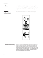
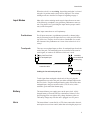
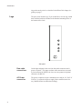
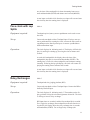
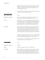
Pro Pace Clock
and Shot Clock
User Guide
F891 Rev. 1106
Colorado Time Systems
Corporate Office
1551 East 11th Street
Loveland, CO 80537 USA
Sales - 1-800-279-0111 or +1 970-667-1000
Service: 1-800-287-0653 x256 or +1 970-667-1000 x256
FAX: 970-667-1032
Web: www.coloradotime.com
Email: [email protected]
Part Number F891 Rev. 1106
© 2006. Colorado Time Systems. All rights reserved.
Table of Contents
1
Introduction
How to Set Intensity and Mode .......................................................1
Intensity .....................................................................................1
Mode ..........................................................................................2
Physical Connections .......................................................................2
Scoreboard/Training ..................................................................2
Input Modes ...............................................................................3
Battery........................................................................................3
Horn ...........................................................................................3
Legs............................................................................................4
2
Pace Clock Operation
Standalone Pace Clock.....................................................................5
Pace Clocks in Series .......................................................................5
Without Timer or Controller......................................................5
With Timer or Controller ..........................................................5
3
Water Polo Operation
Physical Setup..................................................................................7
Displaying Information....................................................................7
Shot time ....................................................................................7
Game time..................................................................................8
Time out time.............................................................................8
Team scores ...............................................................................8
Time of day ................................................................................8
4
Training Modes
Lap counter ......................................................................................9
Simple Pace Clock .........................................................................10
Pace clock with Cumulative Splits ................................................10
Pace clock with Lap Splits.............................................................11
Relay Exchanges............................................................................11
Start Reaction.................................................................................12
Turn Speed .....................................................................................12
Breakout Time ...............................................................................13
Start Reaction and Breakout Time.................................................13
Single Lane Timer .........................................................................14
Mid-Race Timing...........................................................................16
Test Mode ......................................................................................17
5
Scoreboard Modes
Physical Setup................................................................................19
Swimming .....................................................................................20
Lane Times...............................................................................20
Event/Heat ...............................................................................20
Training Pace Clock.......................................................................20
Lane Times...............................................................................20
Diving ............................................................................................20
Dive Number and Position.......................................................20
Current Round/Current Diver ..................................................21
Synchronized Swimming ...............................................................21
Award.......................................................................................21
All Sports .......................................................................................21
Time of Day .............................................................................21
6
Appendix
Firmware prior to 2.0 .....................................................................23
Introduction
1
Introduction
Thank you for purchasing a Colorado Time Systems Pro Pace
Clock/Shot Clock.
Introduction
This introductory chapter describes physical features of your Pro
Pace Clock/Shot Clock. Subsequent chapters describe how to set up
and use your Pro Pace Clock/Shot Clock in a variety of ways.
Pace Clock Operation
Chapter 2, beginning on page 5, describes how to physically set up
single or multiple Pro Pace Clocks for basic pace clock operation.
Water Polo
Chapter 3, beginning on page 7, describes using the units for Water
Polo as shot clocks and also for displaying game time and other
scoreboard data.
Training Modes
Chapter 4, beginning on page 9, describes the training modes, including what the mode does and which other devices are needed for
the mode.
Displaying Other Information
Chapter 5, beginning on page 19, describes using a Pro Pace
Clock/Shot Clock to display additional information. The information
available for display varies by sport.
How to Set Intensity
and Mode
Use the Mode switch on the front panel to set intensity and mode, as
follows:
Intensity
When a Pro Pace Clock is turned on, the clock will first display in
and a number for Intensity. While in is displayed, the Mode switch
adjusts the intensity of the display. Fifteen levels of intensity are
available, from 1 (lowest) to 15/16 (highest). Select the desired intensity.
NOTE: The initial intensity displayed will be the last setting saved
before the clock was turned off. It will not change until the knob is
turned for the first time.
1
Introduction
Mode
Physical
Connections
Scoreboard/Training
2
After the Mode switch has been in the same intensity setting for 4
seconds, the clock will display the firmware revision, and then the
current mode. At this point, the Mode switch changes the mode (and
only the mode) until the clock is turned off and then on again.
The physical connections are on the left side of the front panel.
When the switch is set to scoreboard, and the clock is connected to
a timer or controller through the quarter-inch phono plug (RS-232)
or the round 4-pin connector (RS-485), the clock will display information from the timer or controller based on the clock's Mode switch
setting. See Chapter 3, beginning on page 7, for information that can
be displayed for Water Polo, and Chapter 5, beginning on page 19,
for other information that can be displayed.
Introduction
When the switch is set to training, the training mode that is selected
using the 16-position mode switch will be displayed. The various
training modes are described in Chapter 4 beginning on page 9.
Input Modes
Most of the various training modes require input from one or more
of the following: touchpads, relay platform, pushbutton or start system. Plug the device(s) providing the input into the proper connector(s) on the front panel.
Most input connections are self-explanatory.
Pushbuttons
For all input connectors, a pushbutton operated by a human judge
may be connected to provide input; however, some precision in timing will be lost. The pace clock records to a hundredth of a second,
but a human with a pushbutton can’t come close to that level of accuracy!
Touchpads
There are two touchpad inputs to allow for touchpad input from both
ends of the pool. The touchpad inputs are connected to the same internal signal, so it makes no difference which one is used.
plug into Pace Clock
Pro touchpad input
stackable,
open-ended dual
banana plug
extension cable
Cabling for far end touchpad input
to touchpad
To take input from touchpads at both ends of the pool, plug the
touchpad from one end of the pool into either touchpad input on the
Pro Pace clock. Plug the touchpad from the other end into the other
touchpad input, using an extension cable (CTS SJ series) with a
stackable, open-ended dual banana plug.
Battery
Horn
The internal battery can supply power to the pace clock. A fully
charged battery will run the unit for a minimum of 6 hours. Leave
the unit plugged in overnight to fully charge the battery after use.
The battery charges any time the unit is plugged in to AC power.
The internal horn is controlled by a CTS timer connected to the unit,
and requires no user intervention, other than selecting the proper set-
3
Introduction
ting on the mode switch, as described in the Water Polo chapter, beginning on page 7.
Legs
The pace clock includes legs. If you would like to use the legs, attach
them with the hardware included to the threaded mounting holes in
the bottom of the clock.
Side panel
4
Data cable
connections
On the right end panel, there are four data cable connectors and a
power receptacle. The upper two data cable connections are round,
4-pin connectors for RS-485; the lower two are quarter-inch phono
connectors for RS-232.
AC Power
connection
The power receptacle accepts a standard power cord for 110 VAC. If
220 VAC is required, the power supply can be modified at the factory. Modified units are labeled accordingly.
Pace Clock Operation
2
Pace Clock Operation
Standalone Pace
Clock
For simple pace clock operation, turn the Pro Pace Clock on. Set the
Scoreboard/Training switch to Training, and set the Mode switch to
2. The pace clock will display 02 (for mode 2), and then reset itself
to :00 and begin counting up. After displaying 59:59, the display
rolls over to :00.
Pace Clocks in
Series
Without Timer or
Controller
To run a series of pace clocks without an external controller, set the
Scoreboard/Training switch on the front panel of the first pace clock
to Training, and set the Mode switch to 2. Set the other pace clock(s)
to Scoreboard and Mode 1. Connect the pace clocks with data cables
using the round 4-pin (RS-485) connectors. All connected pace
clocks will display the same information.
Turn the pace clocks on with the power switch on the front panel.
The pace clocks will begin counting up from zero, displaying time as
minutes and seconds. After displaying 59:59, the displays will roll
over to :00.
With Timer or
Controller
A clock or series of clocks can be controlled using a CTS timer or
pace clock controller. The clock(s) will display information from the
timer or pace clock controller based on the setting of the Mode dial.
See Chapter 3 starting on page 7 for specifics about Water Polo, and
Chapter 5 starting on page 19 for specifics on other sports.
5
Pace Clock Operation
6
Water Polo Operation
3
Water Polo Operation
Physical Setup
Mode Switch Setting
Display
1
Game Clock
3
Shot Clock
5
Time Out Clock
12
Team Scores
16
Time of Day
Clocks connected to a CTS timer running Water Polo software can
be used to display all of the information shown in the chart above.
Set the Scoreboard/Training switch to Scoreboard. Connect one
clock to the timer through the scoreboard output port with a data cable using either the round 4-pin (RS-485) connector or the quarter-inch phono connector (RS-232), whichever your timer supports.
Connect the clocks to each other with the same type of data cable.
Each clock will display the information based on its mode setting: a
series of connected clocks will display different information from
one another if they are set to different mode settings.
Displaying
Information
Clocks can be used to display shot time and other information for
Water Polo, with the timer default settings. Connect them as described in Physical Setup. Turn the clock(s) on. Set the Training/Scoreboard switch to Scoreboard. The clock(s) will display information from the CTS timer based on the setting of the Mode dial.
See your CTS timer Water Polo software manual for information
about shot time, game time, time out time, team scores or setting
time of day.
Shot time
To display shot time on clocks, the CTS timer must be set to display
Scoreboard Channel 02 (shot time) on Module 03. Set the Mode
7
Water Polo Operation
switch to 3 on these clocks. The CTS timer will automatically start
and stop the shot clocks and sound the horns.
8
Game time
To display game time on a clock, the CTS timer must be set to display Scoreboard Channel 01 (game time) on Module 01. On this
clock, set the Mode switch to 1. The CTS timer will automatically
start and stop the game clock and sound the horn at the end of each
period.
Time out time
To display the amount of time remaining in a time out on a clock, the
CTS timer must be set to display Scoreboard Channel 12 (time out
time) on Module 05. On this clock, set the Mode switch to 5. The
CTS timer will automatically start and stop the time out clock.
Team scores
To display team scores, the CTS timer must be set to display Scoreboard Channel 5 (team scores) on Module 0D. On this clock, set the
Mode switch to 12. The CTS timer will automatically display and
update the team scores. By default, the dark team score will be displayed on the two left digits, and the light team score will be displayed on the two right digits. On newer timers, this can be reversed
through timer setups.
Time of day
To display the time of day, the CTS timer must be set to display
Scoreboard Channel 10 (time of day) on Module 16. On this clock,
set the Mode switch to 16. The CTS timer or controller will automatically send the time of day to the clock.
Training Modes
4
Training Modes
Mode #
Mode Description
See Page #
1
Lap counter
9
2
Simple pace clock
10
3
Pace clock with cumulative splits
10
4
Pace clock with Lap Splits
11
5
Relay Exchanges
11
6
Start Reaction
12
7
Turn Speed
12
8
Breakout Time
13
9
Start Reaction and Breakout Time
13
10, 11, 12, 13, 14
Single Lane Timer (1, 2, 3, 4 or multiple laps)
14
15
Mid-race Timer
16
16
Test Mode
17
Lap counter
Mode 1
Equipment required:
Touchpad required; start system or pushbutton can be used to reset
the clock.
Set up:
Connect the touchpad to either Touchpad input. If using a start system or pushbutton for resetting the display, connect the start system
or a pushbutton to the Start System input, or connect a pushbutton to
the Reset/Breakout input.
9
Training Modes
Operation:
The clock displays 01, indicating mode 1. The display will flash, and
then show 0, indicating 0 laps completed. Each valid touchpad hit
will cause the display to count up by 1.
A start input (either a start signal from the start system or one click
on a pushbutton connected to the start input) or a double click on a
pushbutton connected to the reset/breakout input will reset the counter to 0.
Simple Pace Clock
Mode 2
Equipment required:
None required for basic operation; start system or pushbutton can be
used to reset the clock.
Set up:
If using a start system or pushbutton for resetting the clock, connect
the start system or a pushbutton to the Start System input, or connect
a pushbutton to the Reset/Breakout input.
Operation:
The clock displays 02, indicating mode 2. The display will flash, display :00, and begin counting up, showing the time as minutes and
seconds. After displaying 59:59, the display will roll over to 00:00.
A start input or a double click from the reset input will reset and start
the clock.
Pace clock with
Cumulative Splits
Mode 3
Equipment required:
Touchpad required; start system or pushbutton can be used to reset
the clock.
Set up:
If using a start system or pushbutton for resetting the clock, connect
the start system or a pushbutton to the Start System input, or connect
a pushbutton to the Reset/Breakout input. Connect the touchpad to
either Touchpad input.
Operation:
The clock displays 03, indicating mode 3. The display will flash, display :00, and begin counting up, showing the time as minutes and
seconds.
At each valid touchpad hit, the display shows the time of the
touchpad hit (cumulative split) in seconds and hundredths (SS.HH).
Meanwhile, the running time continues internally. Following the cumulative split display the clock will resume displaying the running
time as minutes and seconds. Once the running time is above a min-
10
Training Modes
ute, the time of the touchpad hit is shown alternating between seconds and hundredths (SS.HH) and minutes and seconds (MM:SS).
A start input or a double click from the reset input will reset and start
the clock any time the running time is displayed.
Pace clock with Lap
Splits
Mode 4
Equipment required:
Touchpad required; start system or pushbutton can be used to reset
the clock.
Set up:
Connect the touchpad to either Touchpad input. If using a start system or pushbutton for resetting the clock, connect the start system or
a pushbutton to the Start System input, or connect a pushbutton to
the Reset/Breakout input.
Operation:
The clock displays 04, indicating mode 4. The display will flash, display :00, and begin counting up, showing the time as minutes and
seconds.
At each valid touchpad hit, the display shows the time of the
touchpad hit (lap split) in seconds and hundredths (SS.HH). The
running time is reset to 0 at the touchpad hit, and continues running
internally. Following the lap split display, the clock will resume displaying the running time as minutes and seconds.
A start input or a double click from the reset input will reset and start
the clock any time the running time is displayed.
Relay Exchanges
Mode 5
Equipment required:
Touchpad and relay judging platform (RJP).
Set up:
Connect the touchpad to either Touchpad input. Connect the RJP to
the Relay Platform input.
Operation:
The clock displays 05, indicating mode 5. The numbers on the display go blank, leaving the colon and rightmost decimal lit. The clock
is waiting to record a relay exchange.
RJP input times are recorded, and the first touchpad hit is recorded.
For a legal relay exchange (the touchpad hit occurred before the relay takeoff), the display shows the relay exchange time in seconds
and hundredths (SS.HH). For an illegal relay exchange (the
11
Training Modes
touchpad hit occurred after the relay takeoff), the display shows the
difference between the two, preceded by a minus sign. If no valid
RJP input is detected within 2 seconds of a touchpad input, “Err”
will be displayed on the clock.
The clock displays the exchange time for 10 seconds, and then automatically resets itself for the next exchange.
Start Reaction
Mode 6
Equipment required:
Start system or pushbutton, and touchpad for backstroke starts or
RJP for starting block starts. Optional pushbutton for reset.
Set up:
Connect the start system or a pushbutton to the Start System input.
For backstroke starts, connect the touchpad to either Touchpad input.
For starting block starts, connect the RJP to the Relay Platform input. If you would like to use a pushbutton to reset the clock after a
start has been recorded, connect a pushbutton to Reset/Breakout.
Operation:
The clock displays 06, indicating mode 6. The numbers on the display go blank, leaving the colon and the rightmost decimal lit. The
clock is waiting for a start input. The start input starts the clock and
the display counts up in hundredths of a second for 2 seconds. All
touchpad or RJP inputs detected during this time are recorded, and
the last one recorded is displayed at the end of the 2-second window.
The start reaction time (the difference between the start input and the
swimmer’s departure) is displayed until the clock is reset with a double click from the Reset/Breakout input, or a new start input.
If a start input is received and no RJP or touchpad input is detected
within 2 seconds, the clock will display “Err.”
Turn Speed
Mode 7
Equipment required:
Touchpad
Set up:
Connect the touchpad to either of the Touchpad inputs.
Operation:
The clock displays 07, indicating mode 7. The numbers on the display go blank, leaving the colon and the rightmost decimal lit. The
clock is waiting for a touchpad input (typically hand touch). All
touchpad releases detected during the next 3 seconds are recorded.
The last one recorded (departure) is displayed at the end of the 3-sec-
12
Training Modes
ond window, showing the time it took for the turn (the difference between the two).
The clock displays the turn time for 10 seconds, and then automatically resets itself for the next turn.
Breakout Time
Mode 8
Equipment required:
Start system, and breakout timer or pushbutton.
Set up:
Connect the start system to the Start System input, and connect the
pushbutton or other breakout timer to the Reset/Breakout input.
Operation:
The clock displays 08, indicating mode 8. The numbers on the display go blank, leaving the colon and the rightmost decimal lit. The
clock is waiting for a start input. The start input starts the clock and
the display counts up in hundredths of a second until a breakout input is detected.
The breakout time (the difference between the start input and breakout input) is displayed until the clock is reset with a double click
from the Reset/Breakout input, or until a new start input starts the
clock from zero.
Start Reaction and
Breakout Time
Mode 9
Equipment required:
Start system, breakout timer or pushbutton, and touchpad or relay
platform.
Set up:
Connect the start system to the Start System input, and connect the
pushbutton or other breakout timer to the Reset/Breakout input. Connect the touchpad to either Touchpad input or connect the RJP to the
Relay Platform input.
Operation:
The clock displays 09, indicating mode 9. The numbers on the display go blank, leaving the colon and the rightmost decimal lit. The
clock is waiting for a start input. The start input starts the clock and
the display counts up in hundredths of a second for 2 seconds. All
touchpad or RJP inputs detected during this time are recorded, and
the last one recorded is displayed at the end of the 2-second window.
The clock continues to count internally while it displays this time
(start reaction time). Running time resumes on the display, until a
breakout/reset input is detected. The breakout time is then displayed
13
Training Modes
until the clock is reset with a double click from the Reset/Breakout
input or a new start input.
Single Lane Timer
Modes: 10, 11, 12, 13 and 14
1, 2, 3, 4 or multiple laps
with optional Start Reaction Time
and optional Relay Exchange Time
Equipment required:
Start system or pushbutton, and touchpad; relay platform for start reaction time from starting block starts; pushbutton for timing more
than 4 laps
Set up:
Connect the start system or the pushbutton to the Start System input,
and connect the touchpad to either Touchpad input.
For start reaction time from starting block starts, connect the RJP to
the Relay Platform input. For start reaction time from backstroke
starts, inputs from the touchpad that is already connected will be recorded and used.
For mode 14 (multiple lap timing), connect a pushbutton to the Reset/Breakout input.
Operation:
The clock displays 10, 11, 12, 13 or 14 indicating the mode. These
modes are the same except for the number of touchpad inputs expected. In all five of these modes, the numbers on the display go
blank, leaving the colon and the rightmost decimal lit. The clock is
waiting for a start input. The start input starts the clock and the display counts up in seconds.
Single Lane
Timing:
Start Reaction
The first option in all five modes is start reaction time. All touchpad
or RJP inputs detected during the initial 2 seconds from start input
are recorded, and the last one recorded is displayed at the end of the
2-second window. The start reaction time (the difference between the
start input and the swimmer’s departure) is displayed, after which the
display resumes counting up in seconds.
If there are no touchpad or RJP inputs during the 2 seconds after the
start input, the display simply continues to count up in seconds.
14
Training Modes
Single Lane
Timing:
Lap Timing
(& Length Timing)
For lap timing, this assumes that the touchpad is at the same end of
the pool as the starting blocks, and therefore the swimmer swims to
the other end and back before touching the touchpad. Length timing
can also be done, with a touchpad at each end of the pool: one connected to the Pro Pace Clock at Touchpad 1 and the other at
Touchpad 2 (see page 3 for cabling this option).
At each valid touchpad input, the display shows the time elapsed
since the start input (cumulative split), alternating between seconds
(MM:SS) and hundredths (SS.HH). If the elapsed time is less than a
minute, the display will not alternate; it will show the time in SS.HH
format.
In mode 10 (single lap timing), the display shows the first elapsed
time until a reset or new start input is detected.
In mode 11 (two lap timing with splits), running time continues internally while the display shows the cumulative split. The display
then resumes running time until a second touchpad input is detected,
indicating a second lap completed. This final time is displayed until
a reset or a new start input is detected.
In mode 12 (three lap timing with splits), running time continues internally while the display shows the cumulative split. The display
then resumes running time after displaying each cumulative split until the third touchpad input. This final time is displayed until a reset
or a new start input is detected.
In mode 13 (four lap timing with splits), running time continues internally while the display shows the cumulative split. The display
then resumes running time after displaying each cumulative split until the fourth touchpad input. This final time is displayed until a reset
or a new start input is detected.
In mode 14, running time continues internally while the display
shows the cumulative split. The display then resumes running time
after displaying each cumulative split until a single Reset input is detected. The clock then stops timing after the next touchpad hit. This
final time is displayed until a reset or a new start input is detected.
Single Lane
Timing:
Relay Exchange
Timing
All Single Lane Timing Modes with multiple laps (or lengths, if
length timing is being done) have optional relay exchange timing capabilities at each touchpad hit before the final one.
The first touchpad hit (cumulative split) is recorded, disabling the
touchpad and starting a 2-second window. During the 2-second window, RJP input times continue to be recorded. After the 2-second
15
Training Modes
window expires, RJP input will be disabled and the cumulative split
will be displayed.
If a valid RJP input was detected, the display will then show the relay exchange time. For a legal relay exchange (the touchpad hit occurred before the relay takeoff), the display will then show the relay
exchange time in seconds and hundredths (SS.HH). For an illegal
relay exchange (the touchpad hit occurred after the relay takeoff), the
display shows the difference between the two, preceded by a minus
sign.
If no valid RJP input is detected within 2 seconds before or after a
touchpad input, only the cumulative split will be displayed on the
clock, as described in the Lap & Length Timing section above.
Mid-Race Timing
Mode 15
Mid-race timing is designed to time the middle portion of a race,
eliminating both the start and the finish. It can be done with
touchpads at both ends of the pool, or only at one end.
1) With a touchpad at one end only, the timing will include one lap
and three turns.
2) With a touchpad at each end, the timing will include one length
and two turns.
Equipment required:
Start system or pushbutton, and touchpad(s).
Set up:
Connect the pushbutton to the Reset/Breakout input, or connect the
start system or a pushbutton to the Start System input. If using one
touchpad, connect it to either Touchpad input. If using touchpads at
both ends of the pool, connect the touchpad from one end of the pool
into either touchpad input on the Pro Pace clock. Plug the touchpad
from the other end into the other touchpad input, using an extension
cable (CTS SJ series) with a stackable, open-ended dual banana plug
(see page 3).
Operation:
The clock displays 15, indicating mode 15. The numbers on the display go blank, leaving the colon and the rightmost decimal lit. The
clock is waiting for a touchpad input (first hit of turn). The first
touchpad input starts the clock, and the display begins counting up in
hundredths of a second. The touchpad input is inactive for 3 seconds
after the first hit, to allow the swimmer to exit the pad.
16
Training Modes
The clock records the next touchpad hits. The last one recorded
(push off) is compared with the initial touchpad touch and the difference between the two is displayed.
With a touchpad at one end, this is the time it took the swimmer to
make an initial turn, swim down the lane, turn at the other end, swim
back and complete the turn at the end with the touchpad.
With a touchpad at each end, this is the time it took the swimmer to
make an initial turn, swim down the lane and complete the turn at the
other end.
The clock displays the mid-race time until the clock is reset with a
double click from the Reset/Breakout input, or a start input.
Test Mode
Mode 16
Equipment required:
Depends upon testing.
Set up:
Follow specific instructions from CTS customer service representative.
Operation:
The clock displays 16, indicating mode 16. It will then cycle through
a digit test. Note that the decimal after the third digit is never used,
and will not light during the digit test.
Input ports can also be tested. When an input port receives a signal
the clock shows which input port was triggered, as shown:
Touchpad
PAd
RJP
rJP
Start
StArt
Reset/Breakout
rESET
17
Training Modes
18
5
Scoreboard Modes
Mode Switch
Setting
Sport
Display
1-10
Swimming & Training Pace Clock
Lane Times
11
Swimming
Event/Heat
13
Diving
Dive Number and Position
14
Diving
Current Round/Current Diver
15
Synchro
Award
16
All
Time of Day
For details about displaying Water Polo information, please see
Chapter 3, beginning on page 7.
Physical Setup
A pace clock or series of pace clocks can be controlled using a CTS
timer or pace clock controller. The connected clock(s) will display
information based on the setting of the Mode dial on the clock, as
listed in the chart above, and the sport the timer is running.
Set the Scoreboard/Training switch to Scoreboard. Connect one pace
clock to the timer at the timer's scoreboard output port, or connect it
to the pace clock controller. Use a data cable with either a round
4-pin (RS-485) connector or a quarter-inch phono connector
(RS-232), whichever your timer or controller supports. If you are
connecting multiple pace clocks, connect the pace clocks to each
other with the same type of data cable.
Each clock will display the information based on its mode setting; a
series of connected clocks can display different information from
one another if they are set to different mode settings.
19
Scoreboard Modes
Swimming
Lane Times
Modes 1 - 10
Connect the clock(s) to a CTS timer running Swimming software.
When a clock is switched to one of the modes 1 through 10, it will
briefly display the mode number (01 through 0A). It will then display the minutes and seconds for the corresponding lane, either running time or split time.
Event/Heat
Mode 11
Connect the clock(s) to a CTS timer running Swimming software.
When a clock is switched to mode 11 it will briefly display E: H for
Event/Heat. It will then display the current event number on the left
two digits and the current heat number on the right two digits.
Training Pace Clock
Lane Times
Modes 1 - 10
Connect the clock(s) to a CTS timer running Pace Clock software, or
to a Pace Clock Controller. When a clock is switched to one of the
modes 1 through 10, it will briefly display the mode number (01
through 0A). It will then display the time for the current lane.
Diving
Dive Number and
Position
Mode 13
Connect the clock(s) to a CTS timer running Diving software. When
a clock is switched to mode 13, it will briefly display dn for Dive
Number. It will then display the dive number and position for the
current diver. If the dive number is 4 characters long (e.g., 101B or
403C), the display will show the entire dive number. If the dive
number is 5 characters long (e.g., 5132D or 6142B), the display will
alternate between the first four characters and the final character on a
half second basis.
20
Scoreboard Modes
Current
Round/Current Diver
Mode 14
Connect the clock(s) to a CTS timer running Diving software. When
a clock is switched to mode 14, it will briefly display r: d for Round
and Diver. It will then display the current round number on the left
two digits and the current diver number on the right two digits. This
mode is helpful for large meets so that divers who may not be able to
see the main scoreboard easily can still see the current state of the
event and know when they will be diving again.
Synchronized
Swimming
Award
Mode 15
Connect the clock(s) to a CTS timer running Synchronized Swimming software. When a clock is switched to mode 15, it will briefly
display SY for Synchro. It will then display the tabulated award for
the current routine to the hundredths place (it will not show the thousandths place).
All Sports
Time of Day
Mode 16
Connect the clock(s) to a CTS timer running any sport's software, or
to a Pace Clock Controller. When a clock is switched to mode 16, it
will briefly display tod for Time of Day. It will then display the current time of day as set on the timer or controller.
21
Appendix
Appendix
Firmware prior to 2.0
There was a slight change in the settings of the Mode dial between
Firmware 2.0 and earlier versions. The manual describes Firmware
2.0 and above; if you are using this manual and have a version of
firware below 2.0, use this chart to determine proper setting of the
Mode dial.
The clock displays its firmware version right after it is turned on and
has displayed the intensity setting.
Mode Switch Setting
Scoreboard Displays
Display
Sport
Firmware 2.0
and above
Firmware 1.x
Game Clock
Water Polo
1
2
Shot Time
Water Polo
3
4
Time Out Clock
Water Polo
5
6
Team Scores
Water Polo
12
N/A
Lane Times
Swimming & Training Pace Clock
1-10
2-11
Event/Heat
Swimming
11
N/A
Dive Number and Position
Diving
13
N/A
Current Round/Current Diver
Diving
14
N/A
Award
Synchro
15
N/A
Time of Day
All
16
N/A
Training Displays
Scoreboard/Training Switch
Master (Display & Send info)
Training
Set to desired training mode
(see Chapter 4 beginning on
page 9).
Slave (Receive & display
that info)
Scoreboard
1
A-1
2
Sales: 1-800-279-0111 or 1-970-667-1000
Service: 1-800-287-0653, x256 or 1-970-667-1000
FAX: (970) 667-1032
Web: www.coloradotime.com
Email: [email protected]
Colorado Time Systems
1551 East 11th Street
Loveland, CO 80537 USA