1
0
n
0
]
D
D
Technical Special Provisions
For Bay County Traffic Engineering
]
n
Prepared for:
0
0
0
D
0
D
D
~
:J
~
J
J
J
J
J
Prepared by:
~GENESIS
IEliiJ GROUP
2507 Callaway Road, Suite 100
Tallahassee, Florida 32303
(850) 224-4400
I
J
J
J
J
August, 2010
n
n
Bay County TSP
Table of Contents
Intersection Component List
0
General Notes
3
Traffic Management Center (TMC) Equipment
5
D
Video Decoder
6
l
Video Monitor
9
J
J
Video Switch
12
Web Server Blade
15
0
Field Equipment
D
D
Traffic Cabinet
18
19
Pad Mounted Cabinet
20
Controller
31
Fiber Optic Patch Panel
37
UPS Power Supply
41
]
Network Switch
51
]
Video Encoder
58
l
Video Surge Protection
61
]
Pole Mount Cabinet
64
l
Data Surge Protection with Base
67
J
Low Voltage Power Protection
70
1
0
0
Camera
__]
j
J
_]
1
~
73
Dome Color Camera
74
Video Surge Protection
77
Mounting Bracket
80
Video Detection
82
Signal Equipment
83
I
:-1
::l
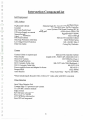
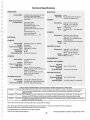
Intersection Component List
~
:l
n
n
D
n
1
0
D
Field Equipment
Traffic Cabinet
Pad Mounted Cabinet
Siemens Eagle EL 712 with Front and Back Doors
Controller
Siemens m50 Series Traffic Controller
Fiber Optic Patch Panel
Coming Cable Systems Wall-Mount Housing (WCH)
UPS Power Supply on separate mounting pad
ALPHA Novis FXM-11 00
Network Switch
RuggedSwitch™ RS900
Video Surge Protection
Edco CX06-M
Pole Mount Cabinet
McCain 336 Controller Cabinet
Data Surge Protection with Base
EDCO PC642 Series
FAS-l-043HC Edco 2
Low Voltage Power Protection
Corning Dry Dielectric
Fiber Optic Cable
D
D
~
Camera
~
Camera Cabinet on separate pad
McCain 336s Controller Cabinet
Video Encoder
impath i4100- FDOT APL #78461401214011
Dome Color Camera
SVFT-PRS35w Vicon 1
Video Surge Protection
EDCO CX06-MI
60ft. Composite Cable Assy.
BH-CCTV-60-CONN Blackhawk 1
BH-CCTV-230
230ft. Composite Cable Only
Power supply for dome and adapter for dome
PRO-SCP-1
Parapet Mount
Pelco PP450
Astro Bracket
Pelco Astro-Brac - Part No. AB-3009-L
_j
*Must include Impath Decoder USG-1100 (w/15' video cable with BNC connectors)
J
Video Detection
:J
:J
:J
:J
J
J
J
Iteris Video Detection Unit
Vantage Edge 2 2N processors per camera
TS 2 IM BIU extension module
Edge connect
RZ4 Advance color cameras
Pelco mast arm brackets
9" black/white video monitor
lteris DIN rail surge panel
J
J
J
J
J
1
n
Signal Equipment
0
1
D
:J
:J
:J
Vehicular Traffic Signal
FDOT Approved Product List
Signal Head Back Plate (Required on East/West Signals)
FDOT Approved Product List
FDOT Specification
Signal Head Pedestal
Signal Head Bracket Extension Pole
FDOT Specification
Countdown Pedestrian Signal
FDOT Approved Product List
Pedestrian push buttons
Polara Engineering, Inc. Bulldog LED
Illuminated Street Name Sign
FDOT Approved Product List
Vehicle Loop Assembly (only if approved by Engineer)
FDOT Specification
Vehicle Loop Detector (only if approved by Engineer)
Eberle Design Inc.(EDI)
Pull Box
FDOT Approved Product List
FDOT Approved Product List
Pull Box (Fiber Optic)
Conduit
FDOT Specification
Signal Cable
FDOT Specification
Electrical Power Supply Assembly
FDOT Approved Product List
Interface Panel
Siemens Eagle
Mast Arm Poles (Galvanized)
FDOT Approved Product List
FDOT Approved Product List
DMS Cabinet (Type 336) Sign Structure Mounted
Daktronics FDOT APL
Dynamic Message Sign
Grounding Arrays
FDOT Specification per ATMS Phase II Plans
:J
~
::t
1
J
]
J
J
J
J
J
J
J
J
2
TECHNICAL SPECIAL PROVISIONS
l
FOR THE
D
BAY COUNTY
0
ADVANCED TRANSPORTATION MANAGEMENT SYSTEM
0
0
D
:J
0
D
These Technical Special Provisions (TSP) expand the current Florida Department of
Transportation's Standard Specifications for Road and Bridge Construction in areas as described
in this document. Any area not covered by these technical special provisions shall be referenced to
the Florida Department of Transportation's Standard Specifications for Road and Bridge
Construction and the District Three (3) TSP'S. These technical special provisions are to replace
any previous specifications or special provisions of Bay County Traffic Control System Field
Equipment.
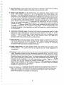
GENERAL NOTES
1. Traffic Control Assemblies: All Traffic Controller Assemblies SHALL meet the conditions
of these Technical Special Provisions for use within the Bay County Traffic Signal Systems.
:J
:J
I
::J
=:I
l
2 . Electrical Services: Any Signalized lntersection(s) within Bay County that requires a new
electrical service to be built or replaced SHAL( require the Contractor to secure all permits.
The Contractor shall be required to coordinate with the County and set up the utility
account that is to be transferred to the City or County. After FINAL acceptance and the
maintenance turned over to the City or the County, the City or County shall be responsible
for payment of electrical power consumed.
3. Controller phasing of the intersection: The controller phasing of the intersection(s) shall
conform to the following: Roadways where the major street is in the north-south orientation,
controller phase 2 SHALL be north bound as the traffic flows . On a roadway that the major
street is in the east-west orientation, then controller phase 2 SHALL be west bound as the
traffic flows. Any roadway that has one leg of the major movement in more of a north-east
or north-west orientation, then that roadway shall be deemed to be a north-south roadway.
Likewise, if one leg of the major movement is more in a north-west to south-west
orientation, then that roadway shall be deemed to be an east-west roadway.
4. Signal Cable Color Codes: The Contractor shall coordinate all Signal Cable Color Codes
with the Traffic Superintendent (850/784-4071 ).
J
J
J
J
J
J
5. Fiber Optic Conduit: The conduit shall have a #12 or larger copper wire installed for the
purpose of locating the fiber cable. This pull wire shall be bonded together at all pull boxes.
6. Fiber Optic Specifications: Fiber optic cable must comply with Phase I ATMS
Specifications. All cable must have dry dielectric and match exact Phase I dimensions. All
specifications of the fiber optic cable to be used in this project are Corning ALTOS Dry
Dielectric.
J
J
3
I
l
n
~
~
0
D
7. Large Pull Boxes: There shall be large pull boxes as described in FOOT Specs. installed
at least every 1200 feet throughout the length of the duct line. (36" x 48")
8. Vehicle Loop Detection: In the design stage of a project, the design engineer shall
provide video detection equipment in lieu of replacement of the vehicle loops at an
intersection. Any Video Detection System on the Approved Products List of the State of
Florida with a current Certificate of Conformance certificate (COC) and that conforms to the
rack mount or size requirements of Bay County Controller Assemblies shall be approved for
use in Bay County. Bay County currently uses and prefers an lteris system. Should
another brand of equipment be selected and approved by the Engineer for use in the field,
then the first system shall include all equipment and software plus 40 hours of training
necessary to set up, modify and use the system. The video detection set up equipment
shall become the property of the FOOT or Bay County depending upon the funding of the
intersection equipment at the completion of the project. All Field equipment shall be
considered the assets of the intersection and shall be included in the normal maintenance
of the intersection.
9. Destruction of Vehicle Loops: All existing Traffic Signal intersections that have the Traffic
Signal Loops Cut or Destroyed due to construction, the Contractor shall notify the Traffic
Engineer of cutting or destruction at least twenty-four (24) hours in advance of such
destruction. The Contractor shall install a Video Detection System and shall have
operational within thirty-six (36) hours of said destruction.
11. Video Detection: In the case where a video detection system is employed, the contractor
may elect, if approved by the FOOT and Bay County Traffic, to transfer ownership of all
such detection equipment at the completion of the project in exchange for eliminating
restoration of traffic signal loops at subject intersection.
12. Traffic Signal Heads: All Traffic Signals Heads shall employ the use of LED's (Light
Emitting Diodes). The colors shall be as approved by the Florida Department of
Transportation.
13. Training: Arrange for at least twenty-four (24) hours of training sessions in the Bay County
Traffic Engineering Division for the maintenance personnel of the County and of any
personnel from the Florida Department of Transportation as recommended by the Traffic
Operations Engineer from District Three. The training sessions will cover controllers, fiber
optic modems, telemetry transceivers or any other specialized equipment that may be
furnished with the installation of a traffic signal/camera location. This school will be
scheduled within 60 days following the delivery of equipment. There shall be no tuition
charge for the participants to attend these sessions. Expenses involving travel , meals and
lodging shall be sustained by the attending personnel. The vendor shall have materials
available for a minimum of six participants.
J
J
J
J
14. Burn-in Period: Once construction of a traffic signal has been satisfactorily completed, the
burn-in period begins. Contractors will be required to respond within two (2) hours to any
malfunction during the burn-in period. Contractor shall provide (3) sets of as built plans
before final acceptance of the signal (no exceptions).
J
J
J
4
n
D
n
1
n
n
n
n
0
0
D
0
0
0
0
0
0
0
Traffic Management
Center (TMC) Equipment
~
0
J
l
___]
J
l
.J
J
J
J
]
5
:J
Video Decoder
:1
:J
J
=:1
J
J
J
J
J
J
1
J
J
J
J
J
6
•
l
I
n
..
·
-
::-,
~
n
-~"-
,, ·
-
-
-
-
-
_._
-.·-
__;!!!~~.li.!.!:t..!*·,; .. :-_~_ ./.r't'i~!:\~~·:,~:r.r:r..~~
- ..··
-..··
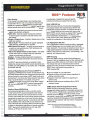
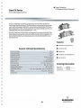
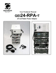
the i-Volution™ 1000
HARDENED ENCODER/DECODER
0
The i-Volution 1000 (ilOOO) Video-over-IP networking solution provides dual channel transport capability for advanced
surveillance applications requiring high resolution, full motion video. The i 1000 can encode or decode two MPEG-1 /MPEG-2
video streams and two serial data channels over standards-based IP networks. The MPEG video streams can be viewed
simultaneously from any PC and/or CCTV monitor in the network.
::::J
The i l 000 is available as a stand-alone dual port video encoder or dual port video decoder.
High Resolution - Full Motion Video
J
1mpath Networks i 1000 provides the highest digitized video quality over
standard IP Ethernet networks. Every image is encoded in rea l-time and
displayed at 30/25 (NTSC/PAL) frames per second. This advanced capability
provides full motion DVD quality video for digital CCTV surveillance
applications.
D
:J
The ilOOO is available as a dual
port Encoder or Decoder.
:=1
.]
J
::J
:J
]
~
_]
I
J
J
applications
• Security Surveillance
o Airports
o Military
o Industrial Complexes
o Hospitals
o Campuses
o Detention Centers
o Residential
• Transportation Monitoring
• Road (ITS)
• Rail/Light Rail
• Subway/Metro
• Industrial Process Control
Dual Channel Capacity
The i 1000 provides dual-channel video connectivity for surveillance
applications supporting two video cameras or monitors co-located within
close proximity. The two serial data ports provide additional support for PTZ,
NMS and POS applications .
Network Scalability and Flexibility
The i 1000 complements the i-Volution product family with enhanced
scalability and functionality at the edge of the network. The stand-alone
ilOOO Encoder/Decoder is ideal for a multitude of surveillance applications
requiring dual channel capability and high quality full motion video.
Advanced features such as On-Screen-Display (OSD) allow network
administrators to display camera name, date, time, resolution, bit rate and
other related information on to any video monitor in the network.
Enhanced IP Multicast Capability - Video & Data
i-Volution simplifies network connectivity via standards-based multicast
t echnology for streaming video and data within an IP network. IP
Multicasting provides the ability to distribute information efficiently to an
unlimited number of remote locations via a single communications interface
at the central site. This flexibility reduces hardware and bandwidth
requirements w hile optimizing the overall network.
Standards Compliant
Video is encoded using standard MPEG-1 /MPEG-2 compression. The video
stream(s) can be viewed by lmpath software/hardware decoders and/or 3
Party products. The video and serial data can be transmitted over any
standard IP network. This includes Ethernet, Gigabit Ethernet, SONET/SDH
and ATM networks.
J
Network Manageability
_]
The ilOOO can be managed both locally and remotely using Telnet,
i-Volution NMS or via 3 Party SNMP network management syst ems.
1
Temperature Hardened
Theil 000 is environmentally hardened to operate over extended operating
ranges and is conformal coated to ensure maintenance free operation.
Class 8 Emissions Certification
Compliance with EN55022 and FCC Class B emission standards make the
ilOOO an idea l solution for both commercial and residential surveillance
applications.
J
I
J
7
:::::-
D ............ . .
D
n
n
n
n
n
D
D
n
rJ
D
D
the i- Volution™ 1000
HARDENED ENCODER/ DECODER
ethernet i nte rface applications
Pan Tilt Zoom
Traffic Controllers
Card Readers
Virtual Message Signs
Weather Stations
Loop Detectors
Weigh-in-motion
Video Detection
SCADA devices
Radar
PC Workstation
Maintenance Applica tions
Video
Analog Video
Channels
IP connectivity
Connector
Digital Encoding
Up to 15 units
NTSC (30 Ips). PAL (25 fps)
2
Unicost and Multicast (UDP)
BNC. 75oh m
MPEG-1 (ISO/IEC 11172-2) and MPEG-2 (ISO/IEC 13818-1 Transport Stream or
ISO/IEC 13818-2 Elementary Steam) MP@ML
128 kbps to 8 Mbps aggregate in Transport Stream and up to 12 Mbps
aggregate in Elementary Stream
Decoder automatically detects incoming MPEG-1 /2 TS orES stream
128 kbps to 12 Mbps aggregate in both Transport and Elementary Stream
NTSC
PAL
720 X 480
720 X 576
352 X 480
352 X 576
352 X 240
352 X 288
192x 128
160x 128
170ms with Optimal Setting
Dolo Rote
Digital Decoding
Data Role
Resolution
Full
HHR
SIF
QSIF
Latency
serial data Interfac e applications
Pan Till Zoom
Traffic Controllers
Card Readers
Virtual Message Signs
Weather Stations
Loop Detectors
Weigh-in-motion
Video Detect ion
SCADA devices
Radar
Data
Format
IP Connectivity
Channels
Connectors
Interface
Data Rate
Sertol I Asynchronous
Unicost and Multicast (UDP)
(2)
DB9-F
EIA-232/422/485- 2/4 Wire. Half/Full Duplex. Software Progromable
300bps to 115.2 kbps
LAN
Format
Channels
Connector
Interface
Data Rote
Protocol
0
D
Encoder
[]
0
i4022
Dual Optics
IEEE 802.3 Ethernet
(1)
RJ45
10/100 Bese-T Ethernet. Half/Full Duplex. Auto-Sensing
10/100 Mbps
TCP, UDP. 1Pv4, IGMPv2. RTP, Diffserv, SAP, SNMPv2
Motion Detection
Zone
Sensitivity
Re-Arm Delay
Full Screen
User Selectable: Low to High (I to 10)
User Selectable: I OOms to 25 seconds
Alarms
Via NMS/SNMP
Video Loss Detection
Video Motion Detection
Unit Configuration Change
i1000
Encoder
D
0
n
11 000
Encoder
J
----L---r-~-------r---------L~---- .s;;<l>
~1
itiz
]
11000
Decoder(s)
VSG
TeleVue
i-Volution NMS
.
~
- ~-=·
~=IJI
:::~::ra.
••
•••••••
::
J
:--
I
•
~·
······•
Power
Input Voltage
Consumption
11.4- 12.6 V DC (.100" center pin diameter lock type connector.)
iiOOO-E =IS W; iiOOO-D = 7 W
Physical
Size
Weight
W 9.1" (23. 1 em)
21bs (.9 kg)
Environmental
Operating Temperature
Rela«ve Humidity
Environmental Protection
-34°C to +74°C
5% to 95%. Non-Condensing
PCB Conformal Coating
Regulatory Approvals
Emissions
Europe
North America
Australia/New Zealand
Immunity
EN55022: 1998. EN61 000-3-2: 1995 & EN61 00-3-3: 1995 Closs B
FCC47 CFR Part 15, Subpart B: 1999 Class B
AS/NZS 3548: 1995 for Class B
EN55024
x H 1.72" (4.37 em) x L 9.1" (23.1
em)
Variant
iiOOO-E
iiOOO-D
MPEG-1 1!.2
Encoder
Decoder
# of Video ports
# of Data ports
2
2
2
2
# of Ethernet ports
-
Control Center 1
_j
Via Serial (Console) Maintenance Port. LED Status Display
Via i-Volution NMS (TeleVue). Telnef, SNMPv2
Via Netw orl< Download- One or multiple units simultaneously
._..:..-¥! ~
J
~ I
Management
Local Management
Remote Management
Software Updates
i4222 EOC
Qj~
1 Unit Reset
Control Center 2
lmpal h Networks Canada Corporation 42 Poyzont Avenu e, Suite 100. Halifax, NS Canada B3B I Z6
T: 902-468-1010 F: 902- 468- 1044 impothnetworks.com
lmpat h Networl<s Ltd. 9 Camelot Drive. Suite 100. Ottowa, O N Canada K2G 5W6
T: 613-226-4000 F: 613-226-4602 impothnetworks.cam
.J
Copyright 2008 lmp o & Networks Can ada Corporation. lmpot h is a registered trademark o f lmpath Networks
Canada Corporation. TeleVue. ClientVue and i-Volution are t rademarks o f lmpath Networks Canada
Corporation All oth e r trademarks ore those o f their respective owners. Printed in Canada - 10!08 .
Specificatio n s su bject to c hange without n otice o r obligatio n .
06mbr_ l 32_ 1OO_i I 000_09.pdf
I
0
D
D
0
0
n
D
0
0
0
D
0
=:I
Video Monitor
:J
:1
.J
:J
J
.J
.J
_]
.J
.J
.J
J
I
J
_j
9
n
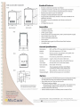
40" and 46" Professional LCD Displays
t1M¥11h1'
• Ultra-thin 11 mm bezels (.43"} create virtually seamless video walls
0
D
1
0
D
• Built -in PC with Windows XPe eliminates need for separate media
player to run content
• 700 cd/m' brightness with brightness sensor and 5,000:1 dynamic
contrast allows placement in even the brightest areas
• Improved panel cooling allows over 20 hours a day usage
• Samsung's proprietary content management software MagiclnfoN Pro
supports both downloading and streaming of files from multiple content
servers, with WAN and LAN networkability
• Exclusive DN ie"' Pro image enhancement technology provides
unsurpassed color and detail
imagine your information or your sales message. big and bright for all the world to see. The
Samsung 400UXn and 460UXn 46" public information displays feature an ultra-thin 11 mm
bezel (less than 1/2") for virtually seamless and distortion-free video walls of up to 5 x 5
(up to 25 monitors). They also feature a built-in CPU, so you don't need a separate media
D
player to run content. And you'll be able to display impressive-looking content over 20
D
hours a day. thanks to advanced cooling technology and lower operating temperatures.
::J
With the Samsung 400UXn and 460UXn 46" displays, it's not hard to imagine.
D
D
~
D
0
J
]
J
J
~
:__]
~
J
.J
.J
n
[1
n
[l
n
D
0
[]
[]
0
D
Ultra-Thin Bezels
Ultra-thin bezel~ of just 11 mm (.4 :l') mean
video walls will be virtually seamless.
Huge Video Walls
Create impossible-to-tgnore video walls
up to 5 monitors wide by 5 monitors l1igh.
Natural Mode correction compensates
for the bezel. tor cjistortion-free displays.
Comectivity
Built-In PC
TI1e but!Hn PC utilizes Windows XPe to
elimnlRle the need for a separate media
player to rLnl content.
Magiclnto? Pro
Sarnsung's proprietary content
management software Magiclnfo'' Pro
supports both downloading and streaming
of files from multiple content servets. witll
WAN and LAN networkabi!tty
High Brightness and Contrast
lndustty-leadtng 700 nits brightness.
a tJrightness sensor that aclju:lts to
ambient ligt1l. and a 5,000:1 dynarnc
contrast that adjusts intensrty based on
the picture allows plaGement in even the
brightest locations.
Operation
Feature
Built for Continuous Use with Reliability
Improved heat protection and dissipation
plates lead to temperatures up to IC
lower than before. for more than 20-hoursa-day operation and longer componertt life.
J
Dimensions 460UXn
J
J
J
Optilml ~ems
:J
Accessories
J
l
1
J
J
J
J
~
n
0
n
0
~
n
1
l
Video Switch
]
J
1
J
J
J
]
J
1
1
J
J
12
"\1
;~
VICON
Corporate Headquarters
89 Arkay Drive
Hauppauge, New York 11788
631-952-CClV (2288)
800-645-9116
Fax: 631-951-CCTV (2288)
Vlcon Europe Headquarters
Brunei Way
Fareham, P015 5TX
UnHed Kingdom
+44 (0) 1489 566300
Fax: +44 (0) 1489 566322
Gennany
vin-videotronlc lnfosystems
gmbh
Lahnstrasse1
D-24539 Neumuenster
Phone: +49 (0) 4321 8790
Fax: +49 (0) 4321 879 97
Far East Office
UnH 5, 17/F, Metropole Square
2 On tfiu Street, Shatln
New Territones
Hong Kong
(852) 2145-7118
Fax: (852) 2145-7117
www.vlcon-cctv.com
Supports Large-Scale Matrix Systems up to
8192 Cameras and 512 Monitors
• Modular configuration enables simple system expansion at any time
• Supports up to 512 keypads, 8192 PTZ or fixed cameras, 8192 alarm inputs and 512
monitors
• Network connectivity through Communication Distribution Unit (CDU) to existing
Vicon® products
• Microsoft® Windows® based Configurator simplifies system programming
The Pilot Ultra™ V1599 Network Video Switch ing
System was developed to satisfy the
Control
needs of large-scale and distributed matrix system
users. The Pilot Ultra System incorporates LAN
communication in a standard, open-architecture
design that lends itself to simple expansion. This
open-architecture desig n permits the easy addition
of keypads, receivers, alarm devices, video switching
units, and host RS-232 controllers.
The Pilot Ultra System is comprised of three main
items: the Pilot V1599 Central Processing Unit (CPU)
that stores all system configuration information,
the Pilot V1599 C DU that can be configured in
multiple ways to act as a gateway from the network
environment to conventional non-network products
and the Pilot 66/99 Card Cage, which connects the
cameras and monitors to the system.
The Pilot V1599 can be configured with hot standby
capability. This capability will allow redundant
components to take over in the event of a primary
system failure.
A Windows-based Configurator provides an intuitive
interface for programming and control of all system
functions, such as:
Network Configuration
Timed or Triggered Event Programming
Keypad Setup
Receiver Profile Configuration
Camera Setup
Titling and Identification of Cameras, Monitors and
Presets
Monitor Setup
Salvo Configuration
Tour Configuration
Alarm Processing Configuration
n
n
Technical Specifications
D
n
D
D
D
OPERATIONAL
MECHANICAL
Compatibility:
Maximum Component
Configurations:
D
D
0
Compatible with all generations oN1500,
V1400 and V1300 matrix system
components, Pilot, NOVA and Surveyor
product lines.
Video Inputs: 8192.
Monitor Outputs: 512.
Receiver/Dome Support: 8192.
XIAAiarm Inputs: 8192.
Keypad/Console/Host RS-232 Support:
512.
Time/Datemtler Outputs: 512.
Video Tour Patterns: 256.
Salvo Switch Configurations: 128.
Application:
Mounting:
Indoor.
All units may be rack mounted in a
standard EIA compliant rack,
Dimensions:
Width (W): 19.0 in. (483 mm).
Depth (D): 17.7 in. (450 mm).
Height (H): 3.5 in. (89 mm).
21.8 lb (9.8 kg).
Front Panel: Gray; Case: Matte black
finish.
V1599CPU
Weight:
Color:
V1599CDU
Dimensions:
ELECTRICAL
D
D
V1599CPU
Input Voltage:
Current:
Power Consumption:
CPU :
RAM Memory:
Hard Drive:
Operating System:
Selectable 120/230 VAC, 50/60Hz.
6Anominal.
300 W nominal
Intel® Celeron 3.06 GHz.
512MB.
80GB.
Windows XP Embedded.
Weight:
Color:
Pilot 66/99 Card Cage
Dimensions:
Wei ght:
Color:
V1599CDU
Input Voltage:
Current:
Power Consumption:
Rear Panel
Controls/Indicators:
J
]
1
Universal 85-265 VAC,
47-60Hz.
300 mA nominal.
36 W nominal.
Network: Two RJ-45 connectors.
Video: Two 25-pin O-shell connectors and
one BNC-F connector.
Alarm: Two 37-pin O-shell connectors.
Serial: Two RJ-45 connectors.
TOT: Two DB-25.
Height (H): 14.0 in. (356 mm).
Width (W): 19.0 in. (483 mm).
Depth (D): 8.5 in. (216 mm).
Approximately 27 lb (12.27 kg).
Front panel: Gray.
ENVIRONMENTAL
V1599CPU and V1599CDU
Operating
Temperature Range:
Operating
Humidity Range:
32 to 113° F (0 to 45° C).
10 to 90%, noncondensing.
Pilot 66/99 Card Cage
Operating
Temperature Range:
Operating
Humidity Range:
Pilot 66/99 Card Cage
Input Voltage:
Current:
Power Consumption:
Width (W): 19.0 in. (483 mm).
Height (H): 5.25 in. (133 mm).
Depth (D): 14.0 in. (355.5 mm) with
external hardware.
21.2 lb (9.6 kg) standard configuration .
Gray.
120-230 VAC, 50/60Hz Auto range.
0.5 A RMS max. Fully loaded card cage.
60 W max. Fully loaded card cage.
32 to 122°F (0 to 50°C).
Up to 95% relative, non-condensing.
_]
Product Codes, Model Numbers and Descriptions for Main Components of Pilot Ultra
V1599CPU
9318-00
.J
Pilot V1599 Central Processing Unit. Includes internal graphic configurator, capable of addressing over 8000 cameras
and 500 monitor and keypad stations. Use with companion Pilot-CDU Communication Distribution Unit and Matrix
Switching System
V1599CDU-1
9319-00
J
Pilot V1599 Communication Distribution Unit. Configured to address 2046 cameras, 128 monitors, 512 receivers, 16
keypads, one RS-232 port and monitor titling. Includes one network interface card and one power supply module.
V1580SCC
6020-80
Pilot66/99 card cage (256x16 or 256x32). Accepts up to 8 switcher boards. Includes motherboard, line sync
board and universal power supply.
J
Refer to the Product Price List for Product Codes of other components and Prepacs.
J
J
J
J
Vicon, its logo and ViconNet are registered trademarks of Vicon Industries Inc. Pilot Ultra is a trademark of Vicon Industries Inc.
Microsoft and Windows are registered trademarks of Microsoft Corporation.
Copyright© 2008 Vicon Industries Inc. All rights reserved.
Vicon part number 8015-5119-00-00
Product specification subject to change without notice.
14
l
n
[]
n
n
[]
0
[l
D
0
D
D
::::J
:J
:J
Web Server Blade
.J
.J
:1
=._]
J
J
J
J
J
]
J
J
J
J
J
15
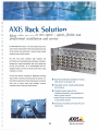
AXlS Rack Solution
More video servers in less space - quick, flexible and
professional installation and service
The AXIS Video Server Rack is a 19" rack solution that can be
used to mount a large number of video servers (typica lly serving
15-20 cameras and upwards) with a common power supply,
providing a space-efficient solution.
The Axis
rack solu t ion combines high
reliabi lity
and
functiona lity with quick, f lexible and prof essiona l installation.
Designed for improved serviceability and quick replacement
of units, the rack holds up to 12 interchangeable and hotswappable blades, so t here is no need for power-down during
installation or service.
The Axis rack solution is designed for applications involving
large number of cameras, both existing and new systems. It is
•
Quick and professional installation of various
video servers in the same rack
•
Expandable system, simply by adding blades
and wiring up
•
Integrated power supply, for easy
installation/expansion, and easy addition of
back-up power solutions
]
•
J
J
Higher density of video channels compared
to stand alone solution
•
Improved serviceability and trouble-free unit
replacement
also ideal for applications handling large physical surveillance
areas such as prisons, airports, large buildings, university
campuses and bus, subway and railway stations.
J
J
J
J
J
J
AXIS~
C OMMUNICA T IONS
16
Make your network smarter
[]
D
AXlS Video Server Rack
D
Hardware Et System
Operating Conditions
Approvals
n
• Aluminum rack, 19" /3U
• Available slots: 12 (support hot swap)
• Temp: 5 - so •c (41 - 122 •FP
• Humidity: 20- 80% RHG
Connections
Dimensions and Weight
• Video: Ana log video input/s (BNC)1
• Power: 100-240 VAC, 50/60 Hz, 1.6 A
•
•
•
•
• EMC:
- CE compliant according to:
+ EN55024:1998 +A1
+ EN61 000-6-1 :2001
+ EN61000-6-2:2001
+ EN55022:1998 +A1 Class B
+ EN61000-3-2:2000
+ EN61000-3-3:1995+A1
- FCC Part 15 subpart B, demonstrated by
compliance with EN55022:1998
- VCCI:2002 Class B ITE
- C-tick AS/NZS 3548
• Safety
- EN60950
0
n
n
0
0
Each slot contains the following connectors on
the rear of the rack:
• Network: 10Base-T/100Base-TX Ethernet
networks (RJ-45)
• Serial communication: RS-232 Et RS-485
(terminal block)
• 1/0 : alarm inputs and outputs (terminal block)2
n
D
0
Height:
Width:
Depth:
Weight:
132 mm (5.2")
482 mm (19.0")
300 mm (11.8")
3.3 kg (7.3 pounds)(incl. PSU)
Shipping contains
• Video server rack
• Power supply module (installed)
• Blanking panels [installed)
• Connector kit
• Mains cable
• Installation guide
1. Video input(s) are located on the blade
2. Number of inputs and outputs varies between different types of Blade.
3. Ensure proper ventilation/cooling when installing multiple racks.
D
D
D
AXlS Blade Video Servers
The following Blade Video Servers are available. Further information will be found
in the respective video server datasheet. Functionality of a blade server is exactly
the same as the stand alone version of the video server.
Each blade is shipped with connector kit, installation guide for video server rack
and the respective video server manual.
J
l
J
Product Selection Guide
Product
No. of
channels
2400 Blade
2410 Blade
Video
compression
Total Frame Rate
(NTSC/PAL)
Video Motion
Detection
Al arm
inputs/outputs
support
4
Motion JPEG
24/20
Yes
4/4
4
Motion JPEG/
MPEG-4
120/100
Yes
30/25
HTIPS
Audio
support
Yes
Yes
No
4/4
Yes
Yes
No
Yes
4/4
Yes
Yes
No
30/25
No
4/1
Yes
No
Yes
PTZ
n
_j
1
_]
241S Blade
1
Motion JPEG/
MPEG-4
250S Blade
1
MPEG-2
w
-
2400+ Blade
4
Motion JPEG
30/25
No
4/1 -
Yes
No
Yes•
2401+ Blade
1
Motion JPEG
30/25
No
4/ 1
Yes
No
Yes•
' R<qUirts th< AXIS 2 19 1 Audro Modulo
NOTE: Please sec separate: datashccts for a!l stand·alone video servers.
.J
]
J
J
www.ax1s.com
Ci:l2Q05, Axis Communications AB. Tt!c Axis logo is a registered trademark of Axis Communications AB. All other company names and products
arc t rademarks or regist ered t radem arks of their respective companies. We. rc:strvc: the right to introduce: modifications without notice.
_]
COMMUNICAT I ONS
17
Make your network smarter
::l
0
D
D
D
D
n
D
0
D
0
D
D
::J
:J
:J
:J
Field Eguipment
"]
J
J
J
J
J
J
J
J
J
1
J
J
18
:l
0
~
LJ
:::J
0
0
n
D
0
[J
Traffic Cabinet
D
D
D
D
D
D
~
]
1. All cabinets should be wired for SOP 10 operations, but should be configured for
the applied intersection.
2. Fiber optic cable must be single mode Corning ALTOS Dry Dielectric
3. Controller shall be Siemens m50 Series Traffic Controller and compatible with
Bay County ATMS system.
4. Cabinet shall have a 16 channel EDI MMU and be Ethernet ready.
5. The cabinet shall be fitted with an external compartment for automatic switching
for an emergency generator.
j
J
J
.J
_]
.J
_]
_]
.J
]
J
19
[]
D
D
0
D
D
D
0
0
0
D
D
D
0
D
Pad Mounted Cabinet
D
D
0
D
0
l
J
___]
_j
.J
.J
.J
.J
.J
J
J
20
Siemens Size P Cabinet
Assembly for NEMA
Specification
Description
The Siemens Size P cab inet
protects electronic co mponents including controllers
and other instrument s. It also
features an aluminum enclosu re for protection from all
forms of outdoor nat ural elements, incl uding rain, sleet,
and snow, as well as seepage
and splash.
Features I Options
• Ou t wa rd rot ating door handle.
• Doubl e-fl anged door frame to provide a better splash shi eld.
• Conti nuously w elded enclosure f or maximum prot ection f rom
contam i nants.
• Unique lock keyi ng combi nations.
• Custom pai ntin g per custome r requirement s.
• Special fan mountin g and air fi lters available.
• Lifting ears
Size P Cabinet Assembly
www. it ssiemen s.com
SIEMENS
Cabinets by Siemens
Door Specifications
0
D
D
D
• Provided with th ree-point locking
mechanism w ith nylon rollers.
• %"-diameter stainless steel outward
turning handle with provisions for
padlocking.
• Main Door lock- industrial standard pin
tumbler lock with #2 key.
• Louvered inlet with filter to prevent dirt
from entering with air flow.
• Closed-cell neoprene door seal gasket
used.
• Heavy gauge stainless steel continuous
hinge utilizing a1/4"-diameter stai nless
steel hinge pin for door support,
carriage bolted in place, for ease of
door removal.
• A 2"-deep, fabricated switch compartment isincluded with a standard
"police" lock and a18-gauge stainless
steel continuous hinge with a
1/8"-diameter hinge pin riveted in
place. Compartment is mounted flush
to the door.
Dimensions and Enclosure
• Completely fabricated from .125"-th ick
type 5052-H32. Vinyl-coated, millfinished aluminum utilizing intermittently we lded construction, subsequently weatherproofed with silicone
sealant.
• Internal attaching components include
six (6) adjustable "C" mounting channels (3 per side), and three (3) slotted
rails on rear wal l for attaching equipment panels.
• The door opening is si ngle-flanged on
top to prevent water drops when the
door is open. The opening also
includes a mount for two dooroperated switches.
• Thermoconvection air ventilation
system utilized with provisions for
mounting fan for forced-air cooling.
Exhaust outlet openings are provided
under the roof over-hang.
• All internal and external hardware
utilizes non-corrosive material.
• Adjustable 3/8"-diameter stai nless
steel door stop can be latched in
various positions.
• Two (2) sheleves included.
Ordering Information
• EL71 2 -Base Mount
All of Siem ens cabinets and accessories are built
with t he hig hest standards in quality and manufacturing. With a long stand ing history o f t echnolog ical innovations, well renowned custo mer
service, and high quality prod ucts and services,
Sie mens is the leader in traffi c t echno logy products and solut io ns. For mo re informat ion on ou r
p roduct line see ou r website at www.itssiemens .
com .
I
]
_]
J
For more advanced fut ure features an/or more info rm at io n on Siemens software products cal l
+ 1. 512.837 .831 0 or tOn tact your local distri buto r (see ll'iebsite for the dealer in your area).
Sier11ens reserve$ tile right to alter any of t11e
Com pany's products or p ublished technical dat a
relating t heret o at any time wit hout not ice.
]
.J
© Siemens 2009. All Rights Reserved
Traffic Solutio ns
8004 Cameron Road, Aust in, TX 70754
Te l. +1.512.837 .03 10 • rax +1. 512 837.01 96
J
www.itssiemens.com
J
22
J
n
n
n
n
0
BAY COUNTY TS2-2 CABINET SPECIFICATIONS
~
D
D
D
D
D
0
l
D
D
~
:J
1.0 CABINET DESIGN AND CONSTRUCTION
1.1 GENERAL
1.1.1 The cabinet and door(s) shall be constructed from type 5052-H32 aluminum with
a minimum thickness of 0.125 inches. All welds shall be neatly formed and free
of cracks, blowholes and other irregularities.
1.1.2 All inside and outside edges of the cabinet shall be free of burrs. All sharp edges
shall be made smooth.
1.1.3 The cabinet shall be designed and manufactured with materials that will allow for
base mounting.
1.1.4 A rain channel shall be incorporated on the main door opening to prevent liquids
from entering the enclosure. Cabinet door openings shall be double flanged
outward to produce the rain channel.
1.1.5 The top of the cabinet shall incorporate a minimum one (1) inch slope toward the
rear to prevent rain accumulation.
:J
1.1.6 The cabinet shall be supplied with a natural aluminum finish. Sufficient care shall
be taken in handling to ensure that scratches are minimized. All surfaces shall be
cleaned of all oil residue and shall be free from weld flash.
:J
1.1.7 All interior seams shall be sealed with RTV sealant or equivalent material.
.J
1.1.8 All cabinets shall be supplied with two removable shelves manufactured from
5052-H32 aluminum having a minimum thickness of 0.125 inches. Shelves shall
have a minimum depth of ten and one-half (1 0.5) inches.
]
_]
J
J
.J
J
J
J
J
J
1.1.9 Three (3) vertical "C" channels shall be mounted on each interior side wall of the
cabinet for the purpose of mounting the cabinet components. The channels shall
accommodate spring-mounted nuts or studs. All mounting rails shall extend to
within four (4) inches of the top and bottom of the cabinets. Rivets or pop-rivets
of any kind shall not be used in the cabinet or on the main panel. No bolts or
screws shall protrude through the outside walls, top, bottom, or sides of the
cabinet.
1.1.1 0 All cabinets shall be supplied with four (4) anchor bolts to properly secure the
cabinet to its base.
1.2 DOOR and HARDWARE
1.2.1 The lower section of the cabinet door shall be equipped with a louvered air
entrance. The air inlet shall be large enough to allow sufficient airflow per the
rated fan capacity. A removable fiberglass air filter shall be supplied with each
23
0
0
n
n
0
0
0
n
0
n
n
D
D
D
~
:1
cabinet. The filter shall be secured to the air entrance in such fashion as to
maintain close contact at all times to the louvered air entrance.
1.2.2 The roof of the cabinet shall incorporate an exhaust plenum with a vent screen .
Perforations in the vent screen shall not exceed 0.125 inches in diameter.
1.2.3 The main door shall be equipped with a three-point draw roller type latching
mechanism. The push rods shall be turned edgewise at the outward supports
and shall be 0.250 inch by 0.750 inch aluminum, minimum.
1.2.4 The handle on the main door shall include a hasp for the attachment of an
optional padlock. The handle shall not extend beyond the perimeter of the main
door at any time. The lock assembly shall be positioned so that the handle shall
not cause any interference with the key when opening the cabinet door. When
the door is closed and latched, the door shall automatically lock. It shall not be
necessary to use a key in order to lock the door.
1.2.5 The main door shall be equipped with a mechanism to automatically hold the
door open at approximately ninety (90), one hundred twenty-five (125), and one
hundred fifty (150) degrees, in windy conditions.
1.2.6 The main door shall be equipped with a #2 tumbler lock. The lock shall be of
brass construction, and shall have a swing away cover. Two (2) No. 2 keys shall
be supplied and attached to each cabinet door upon shipment.
::J
1.2.7 The cabinet shall have a full rear door to allow access to the back of the load
bay.
:J
:J
1.2.8 The rear of the load bay shall be covered by a sheet of Plexiglass to minimize
exposure to the elements when the rear door is open.
.J
1.3 POLICE SWITCH COMPARTMENT
l
1.3.1 A switch compartment shall be provided on the main door.
1
1.3.2 The opening for the switch compartment door shall be double flanged on all four
(4) sides and shall incorporate a rain channel on all four (4) sides.
J
.J
1.3.3 The police door lock shall be of brass construction, and shall have a swing away
cover. All cabinets shall have a police panel door that utilizes a slam shut type
latching mechanism. Two (2) police keys shall be supplied and attached to each
cabinet door upon shipment.
J
.J
J
J
2.0 TYPE 1 TERMINALS AND FACILITIES MAIN PANEL DESIGN
2.1
The main panel shall be constructed from 5052-H32 brushed aluminum of 0.090
inches minimum thickness and formed so as to minimize any flexing when plug-in
components are installed .
J
J
J
24
2.2
All main panels shall be hinged at the bottom to allow easy access to all wiring on
the rear of the panel. The cabinet back panel conductors shall be arranged to
allow the top of the panel to be tilted out through the main cabinet door.
2.3
The main panels shall be fully wired in the following configurations:
Sixteen (16) load switch sockets, (eight (8) vehicle sockets, four (4) pedestrian
sockets and four (4) overlap sockets) eight (8) flash transfer relay sockets, one
(1) flasher socket and two (2) main panel BIU rack positions.
:J
:1
2.4
:J
Up to eight (8) load switch sockets may be positioned horizontally or stacked in
two (2) rows on the main panel. If more than eight (8) load switch sockets are
required they shall be mounted in two (2) horizontal rows.
:J
:1
:J
2.5
A bracket extending at least half the length of the load switch shall support all
load switches. This support must be rigidly mounted to the main panel and be
removable for maintenance by using hand tools only.
2.6
All field output circuits shall be terminated on a non-fused terminal block with a
minimum rating of twenty (20) amps.
2. 7
All main panels shall provide means of programming the controller phase outputs
to load switch inputs with only the use of a screwdriver.
2.8
Permanent alphanumerical labels shall identify all field input/output (1/0)
terminals. All labels shall use standard nomenclature per the NEMA TS 2
Specification.
2.9
All flash color selection shall be accomplished at the field terminals with the use
of a screwdriver only. It shall also be possible to select through terminal
connections, which of the two (2) flasher circuits is connected to each phase. All
cabinet flasher circuit and flash color wiring shall be wired as below or as
specified on the plans.
:J
:1
:J
J
J
J
l
J
J
Flasher circuit output #1 shall be wired for phases 1, 2, 5, 6 and overlap A and
overlap C. Flasher output circuit #2 shall be wired for phases 3, 4, 7, 8 and
overlap Band overlap D. All cabinets shall be pre-wired to flash phases 2 and 6
and overlaps A and C yellow and all other phases and overlaps red.
J
J
J
2.10
Signal output terminals shall be screw type; Compression type termination shall
not be acceptable.
2.11
As a minimum, an RC network shall be wired in parallel with each group of three
(3) flash-transfer relay coils. An RC network shall be installed on all other relay
coils.
2.12
All Controller Unit and Malfunction Management Unit cables shall be of sufficient
length to allow the units to be placed on either shelf. Connecting cables shall be
J
J
J
J
J
J
J
Reference designators for all load switch and flash transfer relay sockets shall be
silk-screen labeled on the front and rear of the main panel.
25
jacketed or sleeved in a braided nylon mesh. The use of exposed tie-wraps or
interwoven cables is unacceptable.
']
:J
::J
]
J
]
J
J
J
J
2.13
All cabinet configurations shall be provided with enough RS-485 Port 1
communication cables to allow full capabilities of the cabinet. Each
communication cable connector shall be a 15-pin metal shell D sub-miniature
type. The cable shall be a shielded cable suitable for RS-485 communications.
2.14
All main panels shall be pre-wired for a Type-16 Malfunction Management Unit.
2.15
All wiring shall be neat in appearance. All cabinet wiring shall be continuous from
its point of origin to its termination point. Butt type connections/splices are not
acceptable. All cabinet back panel conductors shall be soldered, at its destination
point as specified. Printed circuit boards, except for detector rack, loop detector
panel and pedestrian isolation boards, shall not be used on main panels.
2.16
All connecting cables and wire runs shall be secured by mechanical clamps.
Stick-on type clamps are not acceptable.
3.0 POWER PANEL DESIGN AND CONSTRUCTION
3.1
The power panel shall consist of a separate, fully enclosed module, securely
fastened to the lower right side wall of the cabinet. The power panel shall be
wired to provide the necessary power to the cabinet, controller, Malfunction
Management Unit, cabinet power supply and auxiliary equipment.
All
components of the power panel shall be accessible for ease of replacement
without removing any other components or equipment. Adequate space between
components shall be provided for the tightening of all terminals.
3.2
The power panel shall be identical for all cabinets except for breaker sizing. The
power panel shall house the following components:
The main circuit breaker shall be single pole Square-D or approved equivalent
and be rated for a minimum of 30 amperes or more depending on load
requirements of each intersection. This breaker shall supply power to the
controller, MMU, signals, cabinet power supply, and separate breakers used to
split the power feed and auxiliary panels. All breakers shall be installed in a
vertical orientation.
One ( 1) single pole fifteen amp ( 15-amp) breaker labeled "Auxiliary" shall supply
power to the fans, lights and GFCI outlet. The power feed for this breaker shall
not be fed from the load side of the main breaker but will be fed from the main
line feed side.
A 50 amp, 125 VAC radio interference line filter shall be supplied.
A normally open, 60-amp, mercury contactor shall be supplied.
J
J
J
J
26
LJ
n
D
0
One ( 1) insulated AC neutral bus bar with a minimum of twelve ( 12) positions
capable of accepting three #12 wires per position.
n
0
One (1) earth ground bus bar (chassis ground) with a minimum of seven (7)
positions large enough to accept three #12 wires per position.
D
A lightning suppressor, EDCO ACP-340 or equivalent shall be provided.
0
0
4.0 AUXILIARY CABINET EQUIPMENT
4.1
The cabinet shall be provided with a thermostatically controlled ventilation fan
(adjustable between 80-150 degrees Fahrenheit) in the top of the cabinet
plenum.
4.2
A fluorescent lighting fixture shall be mounted on the inside top of the cabinet
near the front edge. The lamp shall be wired to a door-activated switch mounted
near the top of the door. If the main door is closed the lamp will be off.
4.3
A rigid slide-out document tray shall be mounted below the bottom shelf. The tray
shall be of sufficient size and strength to hold a complete set of cabinet wiring
drawings, intersection diagrams, equipment and programming manuals for all
equipment and modules applicable to each cabinet. The tray shall operate by
sliding out, then opening a hinged cover to remove documents. After removing
the documents and closing the cover, the tray shall serve as a suitable resting
place for documents or a laptop computer
4.4
Three (3) sets of complete and accurate cabinet wiring drawings shall be
supplied with each cabinet.
D
[]
0
0
D
0
D
:J
:J
:J
::J
4.5.1 One (1) hard copy set of manuals for the Controller Unit, Malfunction
Management Unit, Power Supply, Detector Rack, Vehicle Detector Amplifier
modules shall be supplied with each cabinet.
J
J
5. 0 VEHICLE DETECTION
_]
5.1
A vehicle detector amplifier rack shall be provided in each cabinet. The detector
rack shall support a minimum of ten (1 0) two (2)-channels loop detectors, and
one (1) BIU, or additional rack positions to accommodate detection requirements
as specified in the plans.
5.2
Each cabinet shall contain detector interface panels for the purpose of
connecting field loops and vehicle detector amplifiers.
5.3
One (1) sixteen (16) position interface panel shall be provided for each twenty
(20) channel detector rack supplied, or additional panels may be provided to
connect all loop detectors required by the plans. The interface panel(s) shall be
attached to the lower left side wall of the cabinet.
_j
:J
.J
~
]
.J
.J
.J
_]
27
n
n
D
0
n
5.4
Each interface panel shall allow for the connection of a minimum of sixteen (16)
independent field loops. A ground bus terminal shall be provided between each
loop pair terminal to provide a termination for the loop lead-in ground wire.
Detector terminals shall be screw type. Compression type termination shall not
be acceptable.
5.5
All interface panels shall be provided with lightning protective devices for all
channels. All interface panels shall be provided with EDCO SRA-6LC or
approved equal lightning protective devices for all available inputs. Pedestrian
inputs, if available on the loop detector panel, will be provided with PC642C-030
lightning suppression.
5.6
All termination points shall be identified by a unique number which is silkscreened on the panel.
5. 7
Each detector rack shall be powered by the cabinet power supply.
D
0
n
0
0
J
0
D
0
D
D
:J
:J
:J
J
_]
J
J
J
I
}
_]
]
6.0 CABINET AUXILIARY SWITCH PANEL AND POLICE PANEL
6.1
An auxiliary switch panel shall be mounted on the inside of the main door. The
auxiliary switch panel shall provide as a minimum the following:
AUTO/FLASH SWITCH. When in the FLASH position, power shall be maintained
to the controller and the intersection shall be placed in flash. The controller shall
not be stop timed when in flash. When the switch is moved from FLASH position
to the AUTO position, an external start signal shall be applied to the controller.
This external start signal will force the controller to initiate the start up sequence
when exiting flash.
STOP TIME ON/OFF SWITCH. When switch is in STOP TIME ON position,
when applied, the controller shall be stop timed in the current interval.
STOP TIME OVERRIDE SWITCH. For additional safety, a stop time override
momentary switch shall be provided to work in conjunction with the main stop
time switch. The momentary stop time override switch prevents the stop time
switch from being left in the stop time state.
EQUIPMENT POWER ON/OFF SWITCH. This switch shall control the Controller
Unit, Malfunction Management Unit and Power Supply AC power. When in the
ON position the AC power shall be applied.
POWER ON/OFF SWITCH. This switch shall totally remove power from the
cabinet including the load bay and flasher.
J
I
~
.J
28
n
D
n
SIGNALS ON/OFF SWITCH. When in the SIGNALS OFF position, power shall
be removed from all signal heads in the intersection. The MMU shall not conflict
or require reset.
0
0
D
VEHICLE DETECTOR TEST 1-8. There shall be a three (3) position TEST-OFFNORMAL toggle switch located in the auxiliary panel for vehicle phases one (1)
through eight (8). In the TEST position, a call will be placed on the respective
phase as long as the switch is held in the TEST position. The toggle switch will
be constructed such that the TEST position is spring-loaded and must be
manually held in this position. In the OFF position, the vehicle detector will not
place a call on the respective vehicle phase. In the NORMAL position, the
vehicle detector for that phase will be enabled to place calls on the respective
vehicle phase when vehicles are detected.
D
D
[]
:J
:J
J
:J
:J
PEDESTRIAN DETECTOR TEST. There shall be a push button type test switch
located in the auxiliary panel for pedestrian phases 2, 4, 6 and 8, or as required
on the plans. The push buttons shall be used to place calls on their respective
pedestrian phases when active.
6.2
AUTO/FLASH SWITCH .
When in the FLASH position, power shall be
maintained to the controller and stop time shall be applied. The intersection shall
be placed in flash. When the switch is moved from FLASH position to the AUTO
position, an external start signal shall be applied to the controller. This will force
the controller to initiate the start up sequence when exiting flash.
~
::J
:J
=:1
AUTO/MANUAL SWITCH.
Cabinet wiring shall include provisions for an
AUTO/MANUAL toggle switch, terminal and a six (6) foot hand cord (to be
included).
:J
J
The police door switch panel shall contain the following :
6.3
All toggle type switches, except those used for detector test purposes, shall be
heavy duty and rated for fifteen 15 amps, at a minimum. Single or double-pole
switches may be provided, as required.
J
6.4
All switch functions shall be permanently and clearly labeled.
J
6.5
All wire routed to the police panel and auxiliary panel shall be adequately
protected against damage from repetitive opening and closing of the main door.
1
]
_j
.J
J
J
J
7.0 AUXILIARY DEVICES
7.1 Load Switches
7.1 .1 Signal load switches shall have a minimum load current rating of 10 amperes at
120 VAG for incandescent lamp load.
]
J
J
29
n
[]
n
"TEMPLE'S FLORIDA TS2 Type 1 Traffic Controller Cabinet Assembly" Specifications
Page 8
D
7.1 .2 The front of the load switch shall embody a minimum of three (3) LED indicators.
n
n
7 .1.3 The minimum amount of load switches shall be supplied with each cabinet to
allow for maximum phase utilization except for the overlaps.
D
D
D
0
n
D
D
D
D
D
D
0
:J
:l
:J
=::1
J
___]
.J
J
_]
:1
.J
7.2 Flashers
7.2.1 The flasher shall be rated at fifteen (15) amperes, double pole with a nominal
flash rate of sixty (60) FPM.
7.3 Flash Transfer Relays
7.3.1 All flash transfer relay contacts shall be capable of making, breaking, with a
contact current rating of twenty (20) amperes.
7.3.2 The coil of the flash transfer relay must be de-energized for flash operation.
7.3.3 The full complement of flash transfer relays shall be supplied with each cabinet to
allow for maximum phase utilization for which the cabinet is designed. A
minimum of six (6) flash transfer relays shall be provided with each controller
assembly.
7.4 Bus Interface Units
7.4.1 All Bus Interface Units (BIU's) shall meet the requirements of the NEMA TS 21998 Standard.
7.4.2 The full complement of (BIU's) shall be supplied with each cabinet to allow for
maximum phase and function utilization for which the controller cabinet is
designed.
7.4.3 Each (BIU) shall include power on, transmit and valid data indicators. All
indicators shall be LED's.
7.5 Vehicle Detection System
7.5.1 All detector racks shall contain the appropriate number of two (2) channel
detector amplifiers to fulfill the detection requirements shown on the intersection
plans.
7.6 24 Volt Power Supply
7.6.1 The TS 2 cabinet power supply shall provide regulated DC power, unregulated
AC power and a line frequency reference for the TS 2-detector rack, (BIU's), load
switches, and other auxiliary equipment. As a minimum, the power supply shall
meet all applicable requirements of the NEMA TS2 Traffic Controller Assemblies
with NTCIP Requirements, 1998.
7.7 EMERGENCY Preemption Panel- Fully functional for preempt operation(s).
7.7.1 A preemption test panel shall be mounted on the left cabinet wall. The panel will
include four (4) pushbutton type test switches connected to the controller
preempt inputs. This panel shall include interface(s) as necessary to implement
the tested preempt(s).
J
:J
.J
30
n
0
D
D
n
D
D
D
D
D
0
D
D
D
D
Controller
D
D
D
0
I
D
I
[J
;__]
J
:._]
0
J
J
31
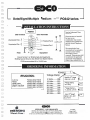
Siemens m50 Series Traffic
Controller
Siemens controller line for use in NEMA style cabinets
Description
Benefits
The Siemens mSO series controllers are an
innovative, fully actuted controller unit with
an extensive compliment of operationa l,
programming, and diagnostic capabilities. The
mSO series exceeds many industry standards
and specifications with advanced functiona lity
beyond the normal NEMA standards. The mSO
features new capabi lities and enhancements
in hardware design and comm unications. The
series consists of the m51 TS2 Type 1, m52 TS2
Type 1,2 and the m53 TS2 Type 2 models.
•
•
Multiple communication interface options
Backward compatible to supports a variety of
cabinet styles including the NEMA TS1 , TS2
Type 1, and TS2 Type 2
Eliminates need for EPROM chip replacement
Abi lity to reduce costs by using single front
panel for multiple controllers
Simple and proven closed-loop solution
Features
Built in external 10 Base-T Ethernet port with
configurable IP
•
8MB of flash memory
NEMA TS2 Type 1 15-pin Input/Output serial
connection to the bus interface unit
NEMA TS2 Type 2 for direct parallel
connection to load switches and detectors
Removable hand held front panel with 8x40
character backlit LCD display
Making motion manageable
SIEMENS
www.itssiemens.com
32
Controllers by Siemens
Central Processor Unit (CPU)
Controller Housing
Open architecture platform with standard
OS9nA operating system
Motorola 68360 32 bit, 25MHz processor
with CPA32 instruction set
•
Seven (7) expansion slots with card guides
for standard size Versa Modules and two
(2) slots with card guides for standard Joint
NEMA/AASHTO.ITE ATC modems (optional)
TOD Clock with automatic daylight savings
time adjustment
Power supply will power the SRAM during
power failures
•
Polycarbonate construction (excluding back
panel), rear mounting tabs and aluminum
power supply mounting plate for electrical
grounding
Carrying Handle
•
Keyboard and Display
Removable light-emitting diode backlit LCD
Display with 8 lines of 40 characters with
adjustable contrast setting.
Emulation of terminal per Joint NEMA/
AASHTO/ITE Standard.
Key quantity and function per Joint NEMA/
AASHTO/ITE Standard.
Communications
•
•
10 Base-T Ethernet with front panel RJ-45
connector
Unique MAC address assigned by the Institute
of Electrical and Electronic Engineers (IEEE)
EIA-232 port for uploading/downloading
applications software and OS updating
Single and multi-mode fiber optic options
1200 bps Frequency Shift Keying (FSK)
modem (optional)
©Siemens 2010. All Rights Reserved.
Traffic Solutions
8004 Cameron Road, Austin, TX 78754
Tel. +1.877.420.2070 • Fax +1 .512.837.0 196
All of Siemens controllers and accessories are
built with the highest standards in quality and
manufacturing. With a long standing history
of technological innovations, well renowned
customer service, and high quality products
and services, Siemens is the leader in traffic
technology products and solutions. For more
information on our product line see our website
at www.itssiemens.com.
For more advanced future features and/or more informat ion on Siemens software products ca ll + 1.877 .420.2070. Siemens reserves the right to alter any of the Company's
products or published technical data relating thereto at any time without notice.
All trademarks used are property of Siemens or their respective owners.
33
M50 and SE-PAC Information
September 2003
Hardware Design
The M50 series controller is designed for efficient operation and ease of
maintenance. The chassis is of injection molded, high impact polycarbonate
and is designed for easy access to the boards for testing without
disassembly. A molded handle makes the lightweight controller easy to
carry. The controller is convection cooled with vent slots in the back and
openings along the bottom. Adjustable rubber feet along the front allow
users to change the angle of the display and create more or less space around
the controller. Grounding metal feet in the rear stabilize the controller.
D
::J
0
:J
SE-PAC Local Controller Software
:J
SE-PAC local software incorporates 20 years of actual "on street" traffic
monitoring and controlling experience. There over twenty thousand
(20,000) local controllers running SE-PAC local controller software
throughout North America. Every state in the United States has a version of
Siemens ITS local controller software installed.
::J
:J
:::J
The software is user-friendly, and it accommodates a variety of traffic
control requirements through its diverse programming configuration
capabilities. The software provides the functional requirements for multiring traffic controller assemblies as described in NEMA Standards
Publications No. TS2-1 998 Traffic Controller Assemblies, and provides all
coordination modes required therein. The software operates in a distributed
mode that makes use of the intelligence in the local controller. The SE-PAC
software supports open architecture.
:J
::J
:J
=:1
Advantages in Programming
:::J
• English Language Menus and user-friendliness;
• Each parameter can be viewed within a menu and a cursor moved to that
parameter for changes;
• Easy verification with related parameters visible simultaneously;
• Programming area identification and editing prompts on the screen;
Traffic Capability Enhancements
J
__]
J
J
•
•
•
•
•
J
l
J
Adaptive Traffic Control;
Multiple Coordination Modes;
Preemption/Priority Routines;
Numerous Standard Reports;
Built-In Diagnostics;
• Time Base Control.
Adaptive Traffic Control Features
l
J
J
Offers simple or highly complex control via:
• 16 Vehicle Phases;
• 16 Pedestrian Phases;
J
Siemens ITS
J
34
Page 2 of 4
n
n
n
M50 and SE-PAC Information
September 2003
[l
• 4 Timing Rings;
["]
• 16 Overlaps;
n
• 80 Detectors;
• Adaptive Maximum Routines;
• Adaptive Protected/Permissive Routines;
0
• Coordination Virtual Split Routine;
D
• Coordination Adaptive Split Routines.
Texas Diamond Intersection Control
D
• Four Phase Diamond mode;
:J
• Basic Three Phase Diamond mode;
• NEMAmode;
:J
• Separate Intersection mode.
:.J
Six Modes of Coordination
• Permissive Mode;
• Yield Mode;
:J
=:1
• Permissive Yield Mode;
• Permissive Omit Mode;
:J
• Sequential Omit Mode;
J
• Full Actuated Mode.
Preemption/Priority Routines
:J
• 6 Preempt Routines providing complete signal control;
.J
• 6 Priority Routines providing complete phase control and in sync return to
coordination .
• Preempt activity can be monitored on a Preempt Status display which denotes
- Preempt In Control, Interval Timing, and Interval Countdown;
.J
:J
• Individual Preempt Status & Timing; Individual Priority Status & Timing.
Extensive Reports
l
• Local Alarm Log;
J
• Comm Fault Log;
• Detector Fault Log;
• System Detector Log;
J
J
• MOE Log; Speed Log;
• Volume Count Log;
]
• Cycle MOE Log.
J
Resident Diagnostic Program
Enhances the maintenance troubleshooting via:
J
• Cycling Diagnostics;
]
• Detector Diagnostics;
• Port 2 Comm Status Display;
J
J
• Port 3 Comm Status Display;
Siemens ITS
35
Page 3 of 4
n
0
M50 and SE-PAC Information
September 2003
D
D
D
• Hardware 1/0 Status Display.
Time Base Control
n
• 250 events for the control of• Pattern Selection,
• Free,
[1
• Flash,
0
• Dinuning,
D
• Detector Diagnostic Parameters,
• System Detector Logging,
0
• 3 Auxiliary Functions,
• 8 Special Functions,
D
• 16 Traffic Functions;
• 99 Day Programs;
D
D
• 10 Week Programs.
NTCIP, ITS & National Architecture Compliance
D
SE-PAC complies with NEMA TS 3.2 - Simple Transportation Management
Framework, and meets the requirements for Conformance Level 2.
D
SE-PAC complies withNEMA TS 3.3- Class B Profile. The Class B objects
have been implemented. All of the NEMA mandatory objects are supported,
as well as many Siemens ITS custom objects.
0
D
NTCIP Conformance defines two conformance levels:
0
0
Conformance Level 1: SNMP version 1 - All supported objects including
Internet standard objects are accessible. This level shall support the Internet
system (group) objects
0
J
Conformance Level 2:
a) Conformance Level 1
b) STMP: All STMP operations
~
c) TMIB: A; mandatory objects & groups defmed within the TMIB
d) Dynamic objects including: definition creation; definition deletion and
object get and set data functions
1
u
The Florida Department of Transportation (http://rite.eng.fsu.edu) has
completed an extensive NTCIP test on the EPAC controller, and it complied
in all areas tested. They are currently in their second round of testing. In
addition, SE-PAC has been submitted to the Georgia DOT and the
Minnesota DOT for NTCIP testing.
]
SE-PAC software is compliant with Texas Regional Comprehensive ITS
Program and the National Architecture.
[J
u
J
~
J
:_j
Siemens ITS
36
Page 4 of 4
:1
n
D
]
n
n
0
0
D
0
D
D
0
D
Fiber Optic Patch Panel
I
0
0
D
D
u
J
:._]
1
:J
:__]
:_]
:.J
~
._1
J
~
~
37
n
n
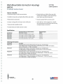
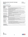
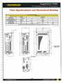
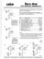
Wall-Mountable Connector Housings
{WCH)
Corning
Cable Systems
A LANscape· Solutions Product
D
D
Applications
Corning Cable Systems Wall-Mountable Connector Housings
provide interconnect or cross-connect capabilities between
the outside plant, riser or distribution cables and the optoelectronics.
D
D
0
D
0
D
0
0
Description
The units can be wall-mounted in main cross-connects
(MCs) or telecommunication rooms (TRs), and are available
in different versions: two panels, four panels, six panels and
12 panels.
Wall-Mountable Connector Housings 1Photo LAN703
Optional products such as the wall-mountable jumper
storage guide kit (WJG-02R) and cable strain-relief kit
(WCH-STRNRLF-KIT) have been designed to make your
wall-mountable product installation easier. The standoff
bracket (WCH-STDOFF-BKT) is designed to extend the
WCH housing from the wall so that cable can be routed
behind the units. Brackets can be stacked to allow a larger
amount of space behind.
D
0
0
WCH-04P (up to 48 fibers) I Drawing CPC-220/S/34
u
D
u
WCH-12P (up t o 144 fibers) I Drawing CPC-220/S/31
1
:__]
WCH-02P (up to 24 fibers) I Drawing CPC-220/S/35
.J
.J
)
.J
.J
_]
WCH-06P (up to 72 fibers) I Drawing CPC-220/S/33
CORNING
38
Product Specif ications
D
D
D
0
D
Wall-Mountable Connector Housings
(WCH)
Corning
Cable Systems
A LANscape· Solutions Product
Features I Benefits
D
• Optimized design for field connectorization
D
• Suitable for loose tube and tight-buffered fiber optic cables
• Optional splice tray holder allows easy cable
routing and is designed to make field splicing
easier; splice trays ordered separately
0
• Metal cabinet construction
• Accepts standard CCH connector panels
• Jumper routing guides and jumper strain-relief point
• -04P, -06P and -12P housings have a durable,
clear polycarbonate-tinted jumper door for easy
viewing of jumper connections
0
0
• Optional field-installable lock kit
D
Specifications
D
Part Number
WCH-12P
WCH-06P
WCH-04P
WCH-02P
• Includes bracket for buffer tube fan-out kits
0
D
Dimensions (Doors in Closed Position)
(H X W X D)- em (in)
34.3 X 57.1 X 13.0 (13.5 X 22.5 X 5.125)
34J X 40.8 X 13.0 (13.5 X 16.062 X 5.125)
34.3 X 40.8 X 10.3 (13 .5 X 16.062 X 4.062)
23.5 X 33.2 X 8.2 (9.25 X 13.25 X 3.25)
Shipping Weight
kg (lb)
4.1 (9.0)
3.3 (7.2)
2.8 (6.2)
2.5 (5.4)
D
D
0
D
0
Ordering Information
Part Number
WCH-12P
WCH-06P
WCH-04P
J
J
D
WCH-02P
Description
Wall-Mountable Connector Housing that will accept up to 12 CCH panels;
twelve 6-fiber panels = 72 fiber total capacity; twelve 8-fiber panels = 96 fiber total capacity;
twelve 12-fiber panels= 144 fiber total capacity
Wall-Mountable Connector Housing that will accept up to six CCH panels;
six 6-fiber panels = 36 fiber total capacity; si..x 8-fiber panels = 48 fiber total capacity;
six 12-fiber panels= 72 fiber total capacity
Wall-Mountable Connector Housing that will accept up to four CCH panels;
four 6-fiber panels = 24 fiber total capacity; four 8-fiber panels = 32 fiber total capacity;
four 12-fiber panels= 48 fiber total capacity
Wall-Mountable Connector Housing that will accept up to two CCH panels;
two 6-fiber panels= 12 fiber total capacity; two 8-fiber panels= 16 fiber total capacity;
two 12-fiber panels= 24 fiber total capacity
u
u
[J
u
u
~
D
u
:J
39
Wall-Mountable Connector Housings
(WCH)
Corning
Cable Systems
A LANscape· Solutions Product
Ordering Information (continued)
Part Number
Accessories
WJG-02R
WCH-STDOFF-BKT
WCH-STDOFF-BKT-2P
BKT-ALL-R23-75
WCH-STRNRLF-KIT
WCH-DUST-CVR
D
WCH-DUST-CVR-D
D
WCH-LBL-KIT
HDWR-LOCK-KIT
D
D
D
Description
Wall-Mountable Jumper Storage Guides that provide jumper management;
kit includes two routing guides and mounting screws
Wall-Mountable Connector Housing Wall Stand-off Brackets for -04P, -06P, -08P and -12P;
brackets provide a l-in spacing from wall
Wall-Mountable Connector Housing Wall Stand-off Brackets for -02P;
brackets provide a l-in spacing from wall
Universal Rack-Mount Bracket for 19-in or 23-in equipment racks; allows for rack-mounting of
the wall-mountable units
Optional Externa l Cable Strain-Relief Kit that utilizes Corning Cable Systems' Universal Cable
Clamp; includes bracket, mounting hardware, one strain-relief clamp and one multicable insert that
will hold up to five cables less than 0.4 inches in diameter
Optional Dust Cover for -04P and -08P housing; covers jumper exits; includes two covers and
mounting hardware
Optional Dust Cover for -06P and -12P housing; covers two jumper exits;
includes two covers and mounting hardware; two kits required for -12P
Replacement Label Kit for WCH
Lock Kit for front door of housing; contains one lock with two keys
Optional Splice Tray Holders
WCH-SPLC-12
Splice Tray Holder for WCH-12P; accommodates twelve 0.2-in-thick (Type 2R) or six 0.4-in-thick
(Type 4R) reduced-length splice trays*
WCH-SPLC-4-8*
Splice Tray Holder for WCH-04P, WCH-06P and WCH-08P; accommodates eight 0.2-in-thick
(Type 2R) or four 0.4-in-thick (Type 4R) reduced-length splice trays
WCH-SPLC-2P*
Splice Tray Holder for WCH-02P; accommodates two 0.2-in-thick (Type 2R) or one 0.4-in-thick
(Type 4R) reduced-length splice trays
Slack Storage
0
WCH-SSH-2*
J
:::J
J
WCH-SSH-4-12*
Wall-Mountable Slack Storage Housing for WCH-02P; accommodates four 0.2-in-thick (Type 2R)
or two 0.4-in-thick (Type 4R) reduced-length splice trays
Wall-Mountable Slack Storage Housing for WCH-04P, WCH-06P, WCH-08P and WCH-12P;
accommodates eight 0.2-in-thick (Type 2R and 2S) or four 0.4-in-thick (Type 4R and Type 4S)
standard or reduced-length splice trays or four UST splice trays
'Splice N't(ys ordered sepanm~y.
Connector Panels
Must be ordered separately
]
=-._]
:::J
:J
~
l
[J
CORNING
40
n
0
D
n
D
D
n
D
D
n
D
0
0
D
UPS Power Supply
D
D
n
0
D
J
J
J
n
J
[J
J
J
J
~
u
41
n
n
Novus FXM UPS Series
Outdoor UPS with 650, 1100, or 2000 W/VA Output
D
D
D
0
Novus FXM UPS
> Clean, uninterruptible backup power ensures your system will remain running
during power outages
> Wide range Automatic Voltage Regulation without going to batteries lengthens
D
D
D
::J
~
battery life, even during periods of surge or sag in the line voltage
> External communications via RS-232 port or (optional) SNMP Ethernet
interface provides local or remote monitoring and control
> Independently programmable and dry contact relays allow tracking and
controlling of key functions
> Event and alarm logging with time and date stamping simplifies and
accelerates troubleshooting
> A wide operating temperature range of -40 to 74°C (-40 to 165°F)
J
J
J
1
1
is suitable
for the most extreme operating environments
> Control and power connection panels can be rotated for mounting and display
in any orientation 2 for viewing convenience
> Temperature compensated battery charging protects batteri es from over
charging at extreme temperatures extending the life of the battery
]
The Novus FXM UPS Series provides constant, reliable backup power for Traffic, Security and Telecommunications
applications. The Automatic Voltage Regulator (AVR) provides power stability in unpredictable environments and
constant voltage during varied power conditions. The Novus FXM UPS Series instantly switches to emergency
backup power during utility power failure or interruptions. Each power level is available in either North American
(120 V) or International (230 V) variants, both with auto-frequency (60Hz/50Hz).
J
' Power module only. Output power derates after 55• c for FXM 650 and 1100. and after 50°C for FXM 2000.
' The LCD panel on the FXM 650 cannot be rotated.
Alpha Technologies
:.J
member of The
ofljfliD GroupTM
42
D
[]
D
n
Novus FXM UPS Power Modules
D
Nominal Specifications
[]
--------------------------------------------------
Power Module:
FXM 1100
FXM 650
North America
D
n
0
]
[1
D
0
D
D
D
D
D
D
J
International
FXM 2000
North America
Intern ational
North America
International
Nominal voltage:
120VAC
230VAC
120VAC
230VAC
120VAC
230VAC
Nominal frequency:
60Hz
50Hz
60Hz
50Hz
60Hz
50Hz
Input current*:
8.7A
4.5A
15.5A
8.0A
20A
12A
Output current:
5.4A
2 .8A
9.1A
4.78A
16.6A
8.69A
Outpu t power at 50°C:
650W/VA
650W/VA
1100W/VA
1100W/VA
2000W/VA
2000W/VA
Output power at 74°C:
500W/VA
500W/VA
850W/VA
850W/VA
1500W/VA
1500W/VA
Battery string voltage:
24VDC
24VDC
48VDC
48VDC
48VDC
48VDC
• At nominal input voltage in and 10A battery charger
General Specifications
Standard Features
Perfo rmanc e
Input voltage range
85 to 175VAC* (to 150VAC for FXM 2000)
120VAC:
150 to 328VAC* (to 281VAC for FXM 2000)
230VAC:
Output voltage
Regulation:
±10% over full input voltage range
Waveform:
Pure sine wave
Typical efficiency
(full resistive load):
>98%
Typical output voltage THO: <3%
Typical transfer time:
<5ms
A udible noise@ 1m:
45dBA
"Without going to batteries
Automatic Voltage Regulation (AVR)
Automatic frequency sensing (60Hz/50Hz)
Remote monitor and control communications options:
Standard RS-232 serial port o r optional internal SNMP Ethernet
interface
Novus User Software: A user friendly WindowsTM based GU I
Emergency Power Off (EPO) input
Variable speed fan with fan failure alarm
Circ uit breaker protection on the input and external battery i nput
Three mounting configurations: wall, shelf or rack
Generator-ready for extended runtim e option
Three user inputs: self test. alarm , shutdown
User adjustable charger (off, 3 A, 6 A , 10 A), 10A default
100 historical events logged with time/date stamping
24 month warranty
Environmental Sj::>ecifications
Operating temperature:
-40 to 74•c (-40 to 165°F)*
Storage temperature:
-40 to 75°C (-40 to 168°F)
Operating altitude**:
12,000fT/3658m
Operating humidity:
Up to95%
·output power for FXM 650 and FXM 1100 is derated by 1.25% per every degree
Celsius above 55°C. Output power for the FXM 2000 is derated by 1.0% per every
degree Celsius above so•c .
--oerate 2•c per 1000ft (305m) above 450011 (1370m)
Shelves
UL1778, CSA 22.2 No 107. 3-03
cCSAusiCE*
Class A FCC/C ISPR
[EN 50091-2:1995]
Electrical safety:
Marks:
EM I:
"CE applies to 230 VAG version only
Mechanical Specifications
Width (in/mm):
FXM 650
FXM 1100
FXM 2000
17/432
15.5/394
15 .5/394
u
Height (in/mm):
3.47/88
5.22/133
5.22/133
Depth (in/mm):
9/229
8.75/222
8.75/222
0
Unit weight (lb/kg):
25/11
35/16
35/16
.·•~:~·
!',
'·.·c:J.··~:.
·· :!!Ii!~.-;:;,··\
.;
• •
~· ,ilrj • . ;.
~
• •I
- 1!1 .. et•lell "
•
• '
.~
~
~
Si! .
f:Zl!%(! •• ti•,_'.1/l; ... _."
J
n
FXM 650
]
The power connection panel
and the control panel can
be rotated for ease of
connection and use in any
J
J
mounting position.
For mor e information v isit www.alpha.com
Alp ha T echno logi es Unite d States
Canada
Bellingham, Washingto n Tel: 360 647 2360 Fax: 360 671 4936 Toll : 1 800 667 8743
B urnaby, British Columbia Tel: 604t JO 1476 Fax: 604 430 8908
11048-157-10 (0812007)
Alpha Technologies reserves the right to make changes to the products and Information contained in this document without notice.
Copyright © 2007 Alpha Technologies. All Rights Reserved. Alpha8 is a registered trademark of Alpha Technologies. member of The Alpha Group'Mis a trademark of Alpha Technologies.
n
D
D
n
Battery Backup System for Traffic Intersections
0
D
D
1
Description. Furnish an Outdoor Hardened Battery Backup System to be installed as a Pad
Mount Stand-Alone Battery Backup System.
2
Materials. Furnish, assemble, fabricate, or install new corrosion resistant materials in
accordance with specifications. Supply a "rack mounted" UPS unit, including a front panel
with indicators and control switches.
D
D
0
3.
Functional Requirements. This specification is for establishing the minimum requirements
for a complete emergency battery backup system for use with Light Emitting Diode (LED)
Traffic Signal Modules at intersections with NEMA, 170 or 2070 cabinets. The Battery
Backup System (BBS) shall include, but not be limited to the following: Inverter/Charger,
Batteries, a separate automatic and manually operated Bypass Switch and all necessary
hardware and interconnect wiring. The BBS shall be capable of providing power for full
run-time operation for an "LED -only" intersection (all colors: red, yellow, green and
pedestrian heads) or flashing mode operation and intersection Red LED's. The BBS shall
be designed for outdoor applications.
4.
Enclosure Construction:
D
D
0
0
D
0
0
0
0
Enclosure. The BBS Enclosure shall be capable of being a Side Mount and Pad Mount.
The enclosure will house the batteries, UPS and bypass switches. The cabinet must meet the
requirements for NEMA 3R enclosures. The housing must have the dimensions so that it
may easily be attached the side of aM, P or 332 Type cabinet. Dimensions of the enclosure
shall not exceed 50"H x 17" W x 17" D. The UPS enclosure must not interfere with the
opening of the traffic cabinet door.
A eight (8) inch Riser option shall be available for Pad Mount installations.
0
~
J
~
l
::J
J
J
D
0
[J
The complete enclosure and door must be made from .125" thick aluminum. All external
seams must be continuously welded. The door opening must have a double flange for
weather sealing purposes.
a.
Door: The cabinet must have a door to provide access to the complete cabinet
interior. The door must include a continuous piano hinge made of 14-gauge stainless
steel and a .120" diameter stainless steel hinge pin. The hinge must be attached to the
enclosure and the door with close end pop rivets. The door must have a three (3) point
locking mechanism with rollers at the ends for the latch rods. The key lock must be a
Corbin cylinder lock with a #2 key. When the door is opened it must have stops at 90,
and 130 degrees. A continuous neoprene gasket must be used to weatherproof the
enclosure when the door is closed.
44
n
[1
n
b. Ventilation Fan: A fan must be mounted in the air baffle at the top of the cabinet
with an air outlet built into the overhang. The fan must be thermostatically controlled.
The bottom of the door must be louvered to allow airflow. A removable dust filter
must be located behind the vent.
n
0
D
0
D
0
c. Finish: The enclosure shall be a natural aluminum or painted ASA 61 Gray.
d. Features: An "On Battery" factory installed high impact red light option shall be
available for the enclosure. The "On Battery" LED shall operate off of the DC
voltage of the UPS to notify that the UPS is on batteries without opening of the door.
The light will be wired to and controlled by the UPS power module. The enclosure
shall be designed to rack mount the UPS and Fail Safe ATS transfer switch. When the
UPS is mounted into the enclosure it must be mounted to accommodate straight-on
horizontal viewing of the LCD screen on the UPS.
0
D
e. Generator Connection: An optional factory installed flush mount generator
compartment with neoprene gaskets for weatherproofing shall be available for the
enclosure. The generator compartment shall include a locking 30 amp plug, L5-30P,
for connecting of a portable AC generator. A manual transfer switch shall be mounted
within the generator compartment to allow for transferring from utility power to
generator power. The generator door will provide a cable slot to allow for closing of
the door when the generator is plugged in and to lock the cable inside of the
compartment. The door will include a Corbin Type 2 lock.
0
D
D
0
0
D
D
0
f. Mounting: The cabinet will be mounted to the traffic control cabinet with six 6 hex
head bolts, \14'' x 20". All holes will be field drilled by the Contractor to
accommodate the specific situation. A grommet must be supplied to protect the cable
in a field drilled 1.5" to 2" hole for cable connection to the existing traffic controller.
The Contractor will supply all the mounting hardware, bolts, washers, nuts, gaskets,
bushings, grommets, caulking, etc., necessary to install the cabinet in a safe and
weatherproof manner.
An optional eight (8) inch Riser shall be available for Pad Mount Stand-Alone
Installations.
0
J
5.
1
u
Ll
Battery System:
a. Individual batteries shall be:
•
Voltage rating: 12V type
•
Amp-hour rating: 100 amp-hour minimum
•
Group size: 31 minimum
•
Batteries shall be easily replaced and commercially available off the shelf.
b. Batteries used for BBS shall consist of 4 batteries. All batteries must meet their
specifications out ofthe box immediately after the initial 24-hour top off charge.
Batteries that require cycling to meet the AH rating specifications are not
acceptable.
J
[J
D
~
45
n
n
D
c. Batteries shall be deep discharge, sealed prismatic lead-calcium based GELNRLA
Gelled Electrolyte/ Valve Regulated Lead Acid). Batteries designed for Cycle
applications, such as Solar, are not acceptable. The battery must be designed for
Standby Applications.
D
d. Batteries shall have a discharge operating temperature range of- 40 octo +71 °C.
D
D
e. Batteries shall have a Manufactures Warranty of 4 Years Full Replacement plus 1
additional year when a battery balancer is used. The warranty shall cover any
battery that does not meet 80% of its original reserve capability during the
warranty period.
D
f. The batteries shall be provided with appropriate interconnect wiring and corrosionresistant mounting trays, shelfs and/or brackets appropriate for the cabinet into
which they will be installed.
D
D
0
D
g. Batteries shall indicate maximum recharge data and recharging cycles.
h. Battery Harness
1) Battery interconnect wiring shall be via two-part modular harness.
2) Part I shall be equipped with red(+) and black(-) 30.48 em (12") cabling that
can be permanently connected to the positive and negative posts of each
battery. Each red and black pair shall be terminated into an Anderson style
Power Pole connector or equivalent.
D
D
0
3) Part II shall be equipped with the mating Power Pole style connector for the
batteries and a single, insulated Power Pole style connection to the
inverter/charger unit. Harness shall be fully insulated and constructed to allow
batteries to be quickly and easily connected in any order to ensure proper
polarity and circuit configuration.
0
4) Power Pole connectors may be either one-piece or two-piece. If a two-piece
connector is used, a locking pin shall be used to prevent the connectors from
separating.
5) All battery interconnect harness wiring shall be UL Style 1015 CSA TEW or
Welding Style Cable or equivalent, all of proper gauge with respect to design
current and with sufficient strand count for flexibility and ease of handling.
]
J
6) Battery terminals shall be covered and insulated with molded boots so as to
prevent accidental shorting.
i.
u
D
Battery Balancer: The battery balancer shall be provided that automatically balances
the battery charge voltage on all batteries in the string to within ±1OOmV between
any two batteries. The Balancer shall allow for any single 12V battery within the
battery string to be replaced at any time throughout the warranty period and not
46
D
n
0
D
j.
k.
ll
I.
m.
n.
n
0
[]
o.
p.
q.
r.
0
0
D
D
0
0
s.
t.
require the purchase of new batteries, to install the battery covered under the
warranty.
The BBS shall provide the ability to manage daylight savings time automatically.
The BBS temperature reporting shall be selectable, Celsius or Fahrenheit.
The BBS shall have the ability to update the firmware via the Web Pages.
The BBS shall be capable of reporting the date in either number or text format in
any order of day, month and year.
The BBS shall have battery runtime reporting integration based on the current rate
of consumption via a selectable collection of common batteries and via generic
configuration with editable Peukert's number.
The BBS shall display the MAC address locally and remotely.
The BBS shall display the unit serial number locally and remotely.
The BBS shall display the record the power consumed by the load. (KW)
The BBS shall have a user input selectable alarm. An alarm shall be sent via SNMP
when activated.
The BBS shall have a remote shutdown I reboot via SNMP feature.
The BBS shall have up to 255 COM ports available on the RS-232.
6. BBS Operation:
a. The BBS shall provide a minimum four (4) hours of full run-time operation at 500
watts with an additional nine (9) hours of Red Flash operation at 125 watts. Typical
values for a "LED-only" intersection. The inverter, when on batteries, shall operate
with a minimum efficiency of84% with a load ranging from 25% to 90% ofthe BBS
total output rating. The BBS shall operate at 97% or higher when operating under
normal condition (utility power is available).
b. The BBS, for safety and efficiency shall operate with a nominal 48 VDC buss. A DC
level higher then 56 VDC shall be considered unsafe and not acceptable.
c. The maximum transfer time allowed, from disruption of normal utility line voltage to
stabilized inverter line voltage from batteries, shall be 5 milliseconds. 5 milliseconds
maximum allowable transfer time shall also apply when switching from inverter line
voltage to utility line voltage.
J
u
d. The BBS shall include a rack mounted Fail Safe Automatic/Manual Bypass Switch
for bypassing the UPS for maintenance. The FS-ATS bypass switch will be a 3-stage
configuration, UPS Normal mode, bypass UPS On and bypass UPS Off. The FSATS Bypass Switch shall mount in a 19" rack inside of the BBS side mount
enclosure.
e.
LJ
The BBS shall provide the user with 6-sets of normally open (NO) and normally
closed (NC) single-pole double-throw (SPDT) individually programmable dry relay
contact closures, available on a front panel-mounted terminal block, rated at a
minimum 120V/1A, and labeled so as to identify each contact.
u
[J
u
47
D
0
n
1)
2)
D
3)
4)
5)
0
6)
f.
D
0
0
One set ofNO and NC contact closures shall be energized whenever the unit
switches to battery power. Contact shall be labeled or marked "On Batt."
A second and third set of N O and NC contact closures shall be energized
whenever the battery approaches approximately 40% of remaining useful
capacity. Contact shall be labeled or marked "Low Batt." This setting must be
adjustable from 10% to 90% via the RS232 connection.
A fourth set ofNO and NC contact closures shall be energized two hours after
the unit switches to battery power. Contact shall be labeled or marked "Timer."
This setting must be adjustable from 1 Min. to 8 Hours via the RS232
connection.
A fifth set of NO and NC contact closures shall be energized in the event that an
Alarm condition occurs. Contact shall be labeled "Alarm".
A 48 VDC output shall be provided for operating an external fan. This output
can also be factory configured as a dry contact
Relay contact activation shall be annunciated on the front panel via a visual
indication. This can be either discreet LED, or part of LCD screen, etc.
The BBS shall have (2) independently programmable timers 0 to 8 hours w ith (2)
times-of-day restrictions on each timer, providing dry contacts to provide Red Flash
operation at user definable times of day.
g. The BBS shall provide 3 user inputs to support Intrusion Alarm, Emergency Power
Off (EPO) and external Self Test (Battery Test).
h. Operating temperature for both the inverter/charger, and manual bypass switch shall
be - 37 °C to +74 oc with a load of850 watts.
1.
The Fail Safe A TS Bypass Switch shall be rated at 240VAC/30 amps, minimum
J.
The BBS shall use a temperature-compensated battery charging system. The charging
system shall compensate over a range of2.5 - 6.0 mV/ °C per cell. The temperature
sensor shall be external to the inverter/charger unit. The temperature sensor shall
come with 2 meters (6' 5") of wire.
J
k. Batteries shall not be recharged when battery temperature exceeds 50 °C ± 3 °C.
]
1.
BBS shall bypass the utility line power whenever the utility line voltage is outside of
the following voltage range: 85VAC to 175VAC (± 2VAC). During a utility input
from 85 VAC to 175 VAC the UPS shall utilize its internal double buck, double boost
regulation to maintain a 108 to 131 V AC output to the controller cabinet, without the
use of the batteries. The BBS shall go into Boost Mode 1 when the AC Line voltage
reaches below 110 V AC, +/- 2volts. When the AC line drops below 96 V AC, +/- 2
volts the BBS shall go into Boost Mode 2. When the AC line voltage reaches 131
volts,+/- 2volts the BBS shall go into Buck Mode 1. When the AC Line voltage
reaches 150 volts the BBS shall go into Buck Mode 2.
m. When utilizing battery power, the BBS output voltage shall be between 112 VAC and
128 VAC, pure sine wave output,~ 3% THD, 60Hz ± 3Hz.
D
u
u
48
l
[]
n
n. BBS shall be compatible with NEMA, 170 or 2170 Controllers, and cabinet
components for full time operation. All loads to the maximum rating of the BBS shall
be powered through the BBS system to utilize the UPS internal Buck/Boost
regulation.
0
0
o. In cases oflow (below 85VAC) or absent utility line power, when the utility line
power has been restored to normal for more than 3 seconds, the BBS shall transfer
from the Boost Regulation Mode or the battery backed inverter mode back to utility
line mode.
D
D
0
p. In cases of high utility line power (above 175VAC), when the utility line power has
been restored to normal for more than 3 seconds, the BBS shall transfer from the
Buck Regulation Mode or battery backed inverter mode back to utility line mode
0
D
q. BBS shall be equipped to prevent a malfunction feedback to the cabinet or from
feeding back to the utility service. For conformation the UPS module must be
UL/CSA approved and labeled. "Tested to" or "Built to" UL/CSA is not acceptable.
D
D
0
r. In the event of inverter/charger failure, battery failure or complete battery discharge,
the Fail Safe Transfer Switch shall revert to the NC (and de-energized) state, where
utility line power or generator power, if available, is connected to the cabinet.
D
s. Recharge time for the battery, from "protective low-cutoff' to 90% or more of full
battery charge capacity, shall not exceed eight (8) hours, unless limited by the
Temperature Regulated charger due to excessive battery heat that could damage the
integrity of the battery string.
0
J
t.
0
7.
u
u
u
1
Batteries shall be Deep Discharge Gel Type Valve Regulated Lead Acid Battery and
compatible with the Battery charger.
Maintenance, Displays, Controls and Diagnostics:
a. The BBS shall include a display and /or meter to indicate current battery charge status
and conditions.
1) The BBS shall provide voltmeter standard probe input-jacks(+) and(-) to read
the exact battery voltage drop at the inverter input.
b. The BBS shall have lightning surge protection option.
c. The BBS shall be equipped with an integral system to prevent battery from
destructive discharge and overcharge.
d. The BBS and batteries shall be easily replaced with all needed hardware and shall not
require any special tools for installation.
e. The BBS shall display via an LCD panel to indicate the number of times the BBS was
activated and the total number of hours the unit has operated on battery power. The
u
~
u
49
0
D
D
LCD display shall show the UPS mode, Alarm status, Input and output voltages,
Output current, Battery voltage, battery charger current and last event. It shall allow
for programming of the battery charger from 3, 6 and 10 amp charger setting.
[l
f.
0
n
The BBS shall include a RS-232 port for local serial communications on the front
panel of the UPS. An optional factory installed internal Ethernet port for SNMP/WEB
communications shall be available.
D
g. The BBS shall include a Microsoft Windows® Graphical User Interface for
programming and monitoring the BBS. This must be provided in addition to the use
of Hyper Terminal and provided at not cost.
D
0
h. Manufacturer shall include a set of operator's manuals with each BBS.
8.
D
0
D
D
Acceptance:
Each BBS shall be manufactured in accordance with a manufacturer Quality Assurance
(QA) program. The QA program shall include two Quality Assurance procedures: (1)
Design QA and (2) Production QA. The Production QA shall include statistically
controlled routine tests to ensure minimum performance levels ofBBS units built to meet
this specification and a documented process of how problems are to be resolved. The
manufacturer, or an independent testing lab hired by the manufacturer, shall perform
Design Qualification Testing on new BBS system(s) offered, and when any major design
change has been implemented on an existing design. A major design change is defined as
any modification, either material, electrical, physical or theoretical, that changes any
performance characteristics of the system, or results in a different circuit configuration.
Production Quality Control tests shall be performed on each new system prior to shipment.
Failure to meet this requirement shall be cause for rejection. Each system shall be visually
inspected for any exterior physical damage or assembly anomalies. Any defects shall be
cause for rejection.
9. Materials Warranty:
u
0
Manufacturers shall provide a two (2) year factory-repair warranty for parts and labor on the
BBS from date of acceptance but not more then 6 months from ship date. Batteries shall be
warranted for full replacement for four (4) years from date of purchase with an additional 1year added when a battery balancer is installed at time of initial installation. A battery shall
be considered bad should it not deliver 80% of its original capability within the stated
warranty period.
The warranty shall be included in the total bid price of the BBS.
J
J
u
50
n
-"]
D
[1
D
[]
D
D
[]
D
D
D
D
D
Network Switch
D
D
J
J
u
u
D
u
u
51
Ethernet Ports
• Up to 9 Ports: 6 Base 10/100BaseTX ports with option
for 3 additional Fiber or Copper ports
• Industry standard fiber optical connectors: LC, SC, ST, MTRJ
• Multimode and Singlemode optical transceivers
• Long haul optics allow distances up to 90km
D
Cyber Security Features
• Multi-level user passwords
• SSH/SSL encryption
• Enable/disable ports, MAC based port security
• Port based network access control (802.1x)
• VLAN (802.1q) to segregate and secure network traffic
• Radius centralized password management
• SNMPv3 encrypted authentication and access security
The RuggedSwitch ™ RS900 is a 9-port industrially hardened,
fu lly managed, Ethernet switch specifically designed to operate
reliably in electrically harsh and climatically demanding
environments.
J
D
]
[J
0
u
The RS900 provides a high level of immunity to
electromagnetic interference and heavy electrical surges
typical of environments found on plant floors or in curb side
traffic control cabinets. An operating temperature range of
-40 to +85"C (-40 to +185"F) coupled with hazardous location
certification (Class 1 Division 2) allows the RS900 to be placed
in almost any location.
The RS900 is packaged in a compact, galvanized
steel enclosure that allows either DIN or panel mounting
for efficient use of cabinet space. The RS900 provides
an integrated power supply with a wide range of voltages
(88-300VDC or 85-264VAC) for worldwide operability or
dual-redundant, reversible polarity, 24VDC and 48VDC
power supply inputs for high availability applications requiring
dual or backup power inputs.
The RS900's superior ruggedized design coupled with
the embedded Rugged Operating System (ROS™) provides
improved system reliability and advanced networking features
making it ideally suited for creating Ethernet networks for
mission-critical, real-time, control applications.
The versatility and wide selection of fiber optics allows
the RS900 to be used in a variety of applications. The RS900
provides up to three 1OOMbps fiber optical Ethernet ports for
creating a fiber optical backbone with high noise immunity and
long haul connectivity.
All RuggedCom products are backed by a five year warranty
and unsurpassed techn ical support.
www.RuggedCom.com
RuggedRatedTM for Reliability in Harsh Environments
• Immunity to EMI and heavy electrical surges
• Meets IEEE 1613 (electric utility substations)
• Exceeds IEC 61850-3 (electric utility substations)
• Exceeds IEC 61800-3 (variable speed drive systems)
• Exceeds IEC 61000-6-2 (generic industrial)
• Exceeds NEMA TS-2 (traffic control equipment)
• Hazardous Location Certification: Class 1 Division 2
• -40 to +85"C operating temperature (no fans)
• Conformal coated printed circuit boards (optional)
Rugged Operating System (ROS™) Features
• Simple plug and play operation - automatic learning,
negotiation, and crossover detection
• RSTP (802.1w) and Enhanced Rapid Spanning Tree
(eRSTP™) network fault recovery (<5ms)
• Quality of Service (802.1 p) for real-time traffic
• VLAN (802.1 q) with double tagging and GVRP support
• Link aggregation (802.3ad)
• IGMP Snooping for multicast filtering
• Port Rate Limiting and Broadcast Storm Limiting
• Port configuration, status, statistics, mirroring, security
• Industrial automation features (eg. Modbus)
Management Tools
• Web-based, Telnet, CLI management interfaces
• SNMP v1 /v2/v3
• Remote Monitoring (RMON)
• Rich set of diagnostics with logging and alarms
Universal Power Supply Options
• Fully integrated power supply
• Universal high-voltage range: 88-300VDC or 85-264VAC
• Dual low-voltage DC inputs: 24VDC
(9-36VDC) or 48VDC (36-72VDC)
• Terminal blocks for reliable
maintenance free connections
RUGGEDCOM
• CSNUL 60950 safety approved
to +85"C
RuggedSwitch™ RS900
.· ~ RUGGEDCOM"
• • INDUSTRIAL S TRENGTH NETWORKs··
RuggedSwitch TM RS900
9-Port Managed Ethernet Switch with Fiber Optical Uplinks
ROS™ Features
RlOS
Rugged Operating
Cyber Security
Cyber security is an urgent issue in many industries where
advanced automation and communications networks play
a crucial role in mission critical applications and where high
reliability is of paramount importance. Key ROS™ features that
address security issues at the local area network level include:
D
0
D
D
0
D
D
• Passwords - Multi-level user passwords secures switch
against unauthorized configuration
• SSH I SSL - Extends capability of password protection
to add encryption of passwords and data as they cross
the network
• Enable I Disable Ports - Capability to disable ports so that
traffic can not pass
• 802.1 q VLAN - Provides the ability to logically segregate
traffic between predefined ports on switches
• MAC Based Port Security - The ability to secure ports on
a switch so only specific Devices I MAC addresses can
communicate via that port
• 802.1x Port Based Network Access Control- The ability
to lock down ports on a switch so that only authorized
clients can communicate via this port
• Radius - Provides centralized password management
• SNMPv3 - encrypted authentication and access security
The ROS™ cyber security features are included to help
address the various industry specific security standards such
as NERC CIP, ISA S99, AGA 12, IEC 62443, ISO 17799:2005
and PCSRF SPP-ICS.
Enhanced Rapid Spanning Tree Protocol (eRSTP ™)
RuggedCom eRSTP allows the creation of fault-tolerant ring
and mesh Ethernet networks that incorporate redundant links
that are 'pruned' to prevent loops. eRSTP yields worst-case
fault recovery 1 of 5ms times the 'bridge diameter' and allows
rings of up to 80 switches. For example, a ring of ten
switches will have fault recovery times under 50ms. eRSTP
implements both STP and RSTP to ensure interoperability
with commercial switches unlike other proprietary 'ring'
solutions.
Quality of Service (IEEE 802.1p)
Some networking applications such as real-time control
or VoiP (voice over IP) require predictable arrival times for
Ethernet frames. Switches can introduce latency in times
of heavy network traffic due to the internal queues that buffer
frames and then transmit on a first come first serve basis.
ROS™ supports 'Class of Service' in accordance with IEEE
802.1p that allows time critical traffic to jump ahead to the
front of the queue thus minimizing latency and reducing jitter
to allow such demanding applications to operate correctly.
ROS ™ allows priority classification by port, tags, MAC
address, and IP type of service (TOS).
www.RuggedCom.com
A configurable "weighted fair queuing" algorithm
controls how frames are emptied from the queues.
System-
VLAN (IEEE 802.1q)
Virtual local area networks (VLAN) allow the segregation
of a physical network into separate logical networks with
independent broadcast domains. A measure of security is
provided since hosts can only access other hosts on the
same VLAN and traffic storms are isolated. ROS™ supports
802.1 q tagged Ethernet frames and VLAN trunks. Port
based classification allows legacy devices to be assigned
to the correct VLAN. GVRP support is also provided to
simplify the configuration of the switches on the VLAN.
Link Aggregation (802.3ad)
The link aggregation feature provides the ability to aggregate
several Ethernet ports into one logical link (port trunk) with
higher bandwidth. This provides an inexpensive way to set up
a high speed backbone to improve network bandwidth. This
feature is also known as "port trunking". "port bundling", "port
teaming", and "ethernet trunk".
IGMP Snooping
ROS uses IGMP snooping (Internet Group Management
Protocol v1&v2) to intelligently forward or filter multicast traffic
streams (e.g. MPEG video) to or from hosts on the network.
This reduces the load on network trunks and prevents
packets from being received on hosts that are not involved.
ROS ™ has a very powerful implementation of
IGMP snooping that:
• Can be enabled on a per VLAN basis.
• Detects and filters all multicast streams regardless of
whether subscribers exist.
• Supports "router-less" operation by supporting an
"active" mode.
• Restores traffic streams immediately after an RSTP
topology change.
SNMP (Simple Network Management Protocol)
SNMP provides a standardized method for network
management stations the ability to interrogate devices from
different vendors. SNMP versions supported by ROS™ are
v1, v2c, and v3. SNMPv3 in particular provides security
features (such as authentication, privacy, and access control)
not present in earlier SNMP versions. ROS™ also supports
numerous standard MIBs (Management Information Base)
allowing for easy integration with any network management
system (NMS).
1 eRSTP fault recovery times may be approximated as follows:
For 100 Mbps, fault recovery performance is <Sms/hop
For 1,000 Mbps, fault recovery performance is <Smslhop + 20ms
RuggedSwitch™ RS900
3
0
. ·~ RUGGEDCOM'
• • INDusTRIAL s TRENGTH NETWORKs··
RuggedSwitchrM RS900
9-Port Managed Ethernet Switch with Fiber Optical Uplinks
I
D
D
[]
0
0
D
D
D
0
ROS™ Features
SNMP (Simple Network Management Protocol) (cont'd)
A feature of SNMP supported by ROS™ is the ability to
generate "traps" upon system events. A NMS can record
traps from multiple devices providing a powerful network
troubleshooting tool. RuggedVuerM is RuggedCom's NMS
that provides graphical visualization of the network and is
fully integrated with all RuggedCom products.
Port Configuration and Status
System•
ROS ™ allows individual ports to be 'hard' configured
for speed, duplex, auto-negotiation, flow control and more.
This allows proper connection with devices that do not
negotiate or have unusual settings. Detailed status of ports
with alarm and SNMP trap on link problems aid greatly in
system troubleshooting.
SNTP (Simple Network Time Protocol)
SNTP automatically synchronizes the internal clock of all
ROS ™ devices on the network. This allows for correlation
of time stamped events for troubleshooting.
Port Statistics and RMON (Remote Monitoring)
ROS TM provides continuously updating statistics per port
that provide both ingress and egress packet and byte
counters as well as detailed error figures. Also provided
is full support for the RMON statistics, history, alarms, and
event groups. RMON allows for very sophisticated data
collection, analysis and detection of traffic patterns.
SCADA and Industrial Automation
ROS™ contains features that optimize network performance
and simplify switch management based on the unique
requirements found in SCADA and industrial automation
applications. Features such as Modbus TCP management for
retrieval of switch data using the ubiquitous Modbus protocol
and DHCP Option 82, a Rockwell Automation ODVA
requirement for IP address assignment based on the location
of the end device, provide capabilities not found in typical
"commercial" or "office grade" Ethernet switches.
Port Based Network Access Control (802.1 x)
ROS™ supports the IEEE 802.1x standard that defines
a mechanism for port-based network access control which
provides a means of authenticating and authorizing
devices attached to LAN ports.
Port Rate Limiting
ROS™ supports configurable rate limiting per port to limit
unicast and multicast traffic. This can be essential to
managing precious network bandwidth for service providers.
It also provides edge security for denial of service
(DOS) attacks.
Broadcast Storm Filtering
Broadcast storms wreak havoc on a network and can cause
attached devices to malfunction. This could be disastrous on
a network with mission critical equipment. ROS™ limits this
by filtering broadcast frames with a user-defined threshold.
Loss of Link Management
Some intelligent electronic devices (lEOs) have dual fiber
optic ports with automatic failover to a backup port should the
primary fail. ROS™ ensures this mechanism works reliably
under all failure modes by appropriately disabling link signals
when required. ROS™ also flushes learned MAC addresses
to ensure the failover occurs quickly.
I
0
]
R(OS
Rugged Operating
Port Mirroring
ROS ™ can be configured to duplicate all traffic on one port
to a designated mirror port. When combined with a network
analyzer, this can be a powerful troubleshooting tool.
www.RuggedCom .com
Event Logging and Alarms
ROS ™ records all significant events to a non-volatile
system log allowing forensic troubleshooting. Events
include link failure and recovery, unauthorized access,
broadcast storm detection, and self-test diagnostics
among others. Alarms provide a snapshot of recent
events that have yet to be acknowledged by the network
administrator. An external hardware relay is de-energized
during the presence of critical alarms allowing an
external controller to react if desired.
HTML Web Browser and Telnet User Interfaces
ROS™ provides a simple, intuitive user interface for
configuration and monitoring via a standard graphical
web browser or via Telnet. All system parameters include
detailed on-line help to make setup a breeze. ROS™ ,
presents a common look and feel and standardized
configuration process allowing easy migration to other ·
RuggedCom managed products.
Configuration via ASCII Text File
All configuration parameters are stored in an ASCII
formatted text file that can easily be transferred via TFTP
or Xmodem. The configuration file can be saved for
backup purposes and easily manipulated by a text editor.
The same text file can be downloaded to the switch at
a later date in order to re-configure or restore
a previous configuration.
Command Line Interface (CLI)
A command line interface can be used in conjunction
with remote shell to automate data retrieval, configuration
updates, and firmware upgrades. A powerful SOL-like
capability allows expert users the ability to selectively
retrieve or manipulate any parameters the device
has to offer.
.
RuggedSwitch™ RS900
4
0
.·; RUGGEDCOM'
• • I NDUSTRIAL STRENGTH NETWORKs··
RuggedSwitch 1 M RS900
9-Port Managed Ethernet Switch with Fiber Optical Uplinks
Technical Specifications
D
D
0
0
Power Supply
• Power Consumption: 10W MAX
• 24VDC: 9-36 VDC, 0.4A
• 48VDC: 36-72 VDC, 0.2A
• HI Voltage ACIDC: 88-300VDC, 85-264VAC, 0.1 A
Network Management
• ROSVue HTTP graphical web-based
• SNMP v1, v2c, v3
• Telnet, VT100
• Command Line Interface (CLI)
Critical Alarm Relay
• Form-e failsafe contact relay: 1A@30VDC
IEEE Compliance
• 802.3-10BaseT
• 802.3u-100BaseTX, 100BaseFX
• 802.3x-Fiow Control
• 802.3z-1000BaseLX
• 802.3ab-1000BaseTX
• 802.3ad-Link Aggregation
• 802.1d-MAC Bridges
• 802.1 d-Spanning Tree Protocol
• 802.1 p-Ciass of Service
• 802.1 q-VLAN Tagging
• 802.1 w-Rapid Spanning Tree Protocol
• 802.1 x-Port Based Network Access Control
Physical
• Height:18.8cm I 7.4"
• Width: 6.6cm I 2.6"
• Depth: 12.7cm I 5.0"
• Weight: 1.22kg I 2.71bs
• Ingress Protection: IP40 (1 mm objects)
• Enclosure: 20 AWG galvanized steel enclosure
• Mounting: DIN rail or panel mounted
Switch Properties
• Switching method: Store & Forward
• Switching latency: 8 us (100Mbps)
• Switching bandwidth: 1.8Gbps
• MAC address table size: 16kbytes
• Priority Queues: 4
• Frame buffer memory: 1 Mbit
• VLANs: 4096
• IGMP multicast groups: 256
• Port rate limiting: 128kbps, 256, 512, 4, 8Mbps
• No head of line blocking
Approvals
· ·Hazardous Locations: Class 1, Division 2
• ISO: Designed and manufactured using a IS09001: 2000
certified quality program
• CE Marking
• Emissions: FCC Part 15 (Class A),
EN55022 (CISPR22 Class A)
• Safety: cCSAus (Compliant with CSA C22.2 No. 60950,
UL 60950, EN60950)
• Laser Eye Safety (FDA/CDRH): Complies with 21
CFR Chapter1, Subchapter J .
EMI Immunity and Environmental Compliance
• IEC 61000-6-2 Industrial (Generic)
• IEC 61800-3 Industrial (Variable Speed Drive Systems)
• IEC 61850-3 Electric Utility Substations
• IEEE 1613 Electric Utility Substations
• NEMA TS 2 Traffic Control Equipment
Warranty
• 5 Years-Applicable to design or manufacturing
related product defects.
IETF RFC Compliance
• RFC768-UDP
• RFC783-TFTP
• RFC791-IP
• RFC792-ICMP
• RFC793-TCP
• RFC826-ARP
• RFC854-Telnet
• RFC894-IP over Ethernet
• RFC1112-IGMP v1
• RFC1519-CIDR
• RFC1541-DHCP (client)
• RFC2030-SNTP
• RFC2068-HTTP
• RFC2236-IGMP v2
• RFC2284-EAP
• RFC2475-Differentiated Services
• RFC2865-Radius
• RFC3414-SNMPv3-USM
• RFC3415-SNMPv3-VACM
IETF SNMP MIBS
• RFC1493-BRIDGE-MIB
• RFC1907-SNMPv2-MIB
• RFC2012-TCP-MIB
• RFC2013-UDP-MIB
• RFC2578-SNMPv2-SMI
• RFC2579-SNMPv2-TC
• RFC2819-RMON-MIB
• RFC2863-IF-MIB
• draft-ietf-bridge-rstpmib-03-BRI DGE-M IB
• draft-ietf-bridge-bridgemib-smiv2-03-RSTP-MIB
• IANAifType-MIB
[]
LJ
www.RuggedCom.com
RuggedSwitch™ RS900
7
. ·~ RUGGEDCOM'
RuggedSwitch
1
M
RS900
9-Port Managed Ethernet Switch with Fiber Optical Uplinks
• • INDUSTRIAL STRENGTH NETWORKs..
Fiber Specifications and Mechanical Drawing
Parameter
Mode
Connectors
Typical Dist. (km)
Optical Wavelength (nm)
Cable SizeCoreiCiadding (urn)
Tx Power (dBm)
Rx Sensitivity (dBm)
Typical Budget (dB)
Fiber Optical Specifications
Fiber Port Type
Multimode
MTRJ I ST I SCI LC
2
1310
50 or 62.51125
-1 5.7
-33.5
Singlemode
LC I SC I ST
50
1310
8 or 91125
20
-15.5
-2.5
-32
-37
17
16.5
34.5
Longer segment lengths dependent on fiber specifications. Consult factory for further details.
- 2.564 -
-
C!.
Rugg~Swttm·
RS900
RS900
o-·o-......
o-· o-......
ii
o-.....
I
..
""
0
0
0.440
4.000
Rug~..
2.5
-39
41.5
4.986
4.590
0.537
o-.....
90
~
'o,..0 0
~o oj
0
<D
~ .;
,..:
--------;.--
~
..
0
<D
,..:
Q ~t~.
DIN- RAIL BRACKET
REMOVED FOR PANEL
MOUNTED UNITS
•0 D
•~;0 D
•~0 Do
•OD
• OD
•00
Hl3~~~
~~
Hil~~£2.!"
·=--===;
I
~l~=
#6 MOUNTING
1 - 0.310
HOLES
0
~
@
.~:
8
"'
..;
$~ 0 ~
www.RuggedCom.com
.
RuggedSwitch™ RS900
8
. ·~ RUGGEDCOM'
• • INDusTRIAL sTRENGTH NETWORKS..
RuggedSwitchTM RS900
9-Port Managed Ethernet Switch with Fiber Optical Uplinks
Order Codes
RS900-_
PS M P7 P8 P9
PS: Power Supply
• 24 = 24 VDC (9-36 VDC)
• 48 = 48 VDC (36-72 VDC)
• HI = 85-264VAC or 88-300VDC
M: Mounting Option
• 0 =DIN RAIL
• P = PANEL MOUNT
• N =NONE
P7, PS, P9: Port 7-9 Options*
0
D
0
D
D
•
•
•
•
•
•
•
•
•
•
•
•
•
00 =No port
TX = 10/100TX (if selected, port 7&8 must both be TX)
MJ = Multimode 1300nm, MTRJ connector
MC = Multimode 1300nm, SC connector
MT = Multimode 1300nm, ST connector
ML = Multimode 1300nm, LC connector
T2 = Singlemode 1310nm, ST connector, Standard 20km
L2 = Singlemode 1310nm, LC connector, Standard 20km
L5 = Singlemode 1310nm, LC connector, Intermediate Reach 50km
L9 = Singlemode 1310nm, LC connector, Long Reach 90km
C2 = Singlemode 1310nm, SC connector, Standard 20km
C5 = Singlemode 131 Onm, SC connector, Intermediate Reach 50km
C9 = Singlemode 1310nm, SC connector, Long Reach 90km
"Note:lf P7 and P8 are selected, they must have the same
connector type.
Example Order Codes
•
•
•
•
•
•
RS900-24-D-OOOOOO
RS900-24-D-TXTXOO
RS900-48-P-TXTXMT
RS900-HI-D-C20000
RS900-HI-D-L2L200
RS900-HI-N-C5C5C9
Options
82-01-0002- Conformal Coating
::J
RuggedCom Inc.
30 Whitmore Road
Woodbridge, Ontario, Canada L4L 7Z4
Tel: (905) 856-5288 Fax: (905) 856-1995
Toll Free: (888) 264-0006
Technical Support Center: (866) 922-7975 or (954) 922-7975
C 2008 RuggedCom Inc.
RuggedSwitch is a trademark of RuggedCom Inc.
Ethernet is a trademark of the Xerox Corporation.
Patent Pending
All specifications in this document are subject to change without notice.
Rev 2-P
www.RuggedCom.com
For additional information on our products and
services, please visit our web site at: www.ruggedcom.com
RuggedSwitch™ RS900
9
0
0
D
0
0
0
D
[]
0
0
D
D
D
D
Video Encoder
D
D
0
D
0
~
[J
0
[J
D
D
0
D
0
0
[J
u
58
D
0
-- - - - - - -
-~
-
~.
0
0
.
-··
-.··
_._
-.--
_.;=.:;;~~·- "~ ~~ft!_;.:~e-~1.:~~~~~":1::-"'~~~~·
-...-
··§:
1
the I-Volutionlt<1 4100
HARDENED ENCODER
The i-Volution 4100 (i4 100) Video-over-IP encoder delivers outstanding performance for advanced surveillance applications
requiring high resolution, full motion video. The i4 100 can encode a single MPEG-1 /MPEG-2 video stream and two serial data
channels for transport over a standards-based IP network. The MPEG video stream can be viewed simultaneously from any PC
and/or CCTV monitor in the network.
0
The i4100 is available as a stond-alone single pori video encoder.
High Resolution - Full Motion Video
1mpath Networks i41 00 provides the highest digitized video quality over
standard IP Ethernet networks. Every image is encoded in real-time and
displayed at 30/25 (NTSC/PAL) frames per second. This advanced capability
provides full motion DVD quality video for digital CCTV surveillance
applications.
Front View
0
0
Single Channel Capacity
The i41 00 provides single-channel video for surveillance applications
supporting dispersed video cameras over an IP network. The two serial data
ports provide additional support for PTZ, NMS and Point of Sales applications.
Network Scalability and Flexibility
The stand-alone i41 00 encoder is ideal for a multitude of surveillance
applications requiring single channel flexibility and high quality full motion
video. Advanced features such as On-Screen-Display (OSD) allows network
administrators to display camera name, date, time, resolution, bit rate and
other related information onto any video monitor in the network. When used
in combination with the Video Motion Detection feature, the i4000 provides
effective, real-time surveillance and alarm notification.
0
0
applications
D
]
D
D
• Security Surveillance
o Airports
o Military
o Industrial Complexes
o Hospitals
o Campuses
o Detention Centers
Enhanced IP Multicast Capability - Video & Data
i-Volution simplifies network connectivity via standards-based multicast
technology for streaming video and data within an IP network. IP
Multicasting provides the ability to distribute informa tion efficiently to an
unlimited number o f remote locations via a single communications interface
a t the centra l site. This flexibility reduces hardware and bandwidth
requirements while optimizing the overall network.
Temperature Hardened
• Transportation Monitoring
o Road (ITS)
o Rail/Light Rail
o Subway/Metro
The i41 00 is designed to meet high availability network requirements. The
unit is environmentally hardened to operate over extended operating
ranges and is conformal coated to ensure maintenance free opera tion.
• Industrial Process Control
Video is encoded using standard MPEG-1 /MPEG-2 compression. The video
slream(s) can be viewed by iMPath software/hardware decoders and/or 3
Party products. The video and serial data can be transmitted over any
standard IP network. This includes Ethernet. Gigabit Ethernet. SO NET / SDH
and ATM networks.
Standards Compliant
D
Network Manageability
The i4100 can be managed both locally and remotely using Telnet.
i-Volulion NMS or via 3 Party SNMP network management systems.
0
59
-···.
--·
~:i
0
0
·:::::
e
•
Iuti
I
4100
HARDENED ENCODER
0
0
ethernet Interface applications
Pan Tilt Zoom
Traffic Controllers
Cord Readers
Message Signs
Weather Stations
Loop Detectors
Weigh-in-motion
Video Detection
SCA DA devices
Ra dar
PC Workstation
M aintenance Applicat ions
Video
Analog Video
Connector
IP connectivity
Digital Encoding
NTSC (30 fps). PAL (25 Ips)
BNC. 75ohm
Unicast a nd Multicast (UDP)
MPEG -1 (ISO/IEC 11172-2) and MPEG-2 (ISO/IEC 13818-t Transport Stream or
ISO/IEC 13818-2 Elementary Steam) MP'ii'ML
128 kbps to 8 Mbps in Transport Stream a nd up to 12 Mbps in
Elementary Stream
NTSC
PAL
720 X 480
720 X 576
352 X 576
352 X 48()
352 X 240
352 X 288
l92x 128
160x 128
l70ms with Optimal Setting
Data Rate
Up to 15 units
serial data Interface applications
Pan Tilt Zoom
Traffic Controllers
i4022 Dual Optics
Card Readers
Message Signs
Weather Stations
Loop Detectors
Weigh-in-motion
Video Detection
SCADA devices
Radar
0
Resolution
Full
HHR
SIF
QSIF
Latency
Dolo
Format
IP Connectivity
Connectors
Interface
Data Rate
Serial I Asynchronous
Unic ast a nd Multicast (UDP)
(2) DB9-F
EIA-232. EIA-422/485- 2 or 4 Wire. Half or Full Duplex software progromable
300b ps t o 115.2 kbps
LAN
LAN Format
Interface
Protocol
IEEE 802.3 Ethernet
RJ 45 I 0/100 Bose-r Ethernet. Half/Full Duplex. Auto-Sensing
TCP. UDP. 1Pv4. IGMPv2, RTP. Diffserv. SAP. SNMPv2
Motion Detection
Zone
Sensitivity
Re-Arm Delay
Full Screen
User Selectable: Low to High (1 to 10)
User Selectable: 1OOms to 25 seconds
Contact Sense & Closure
Connector
Contact Sense
Dry Contact
Maximum Ra ting
Re-Arm Delay
Terminal Block
Output Voltage: +5 VDC. Maximum Resistance: 1.2 K Ohms
Off Leakage: < 1 nA. On Resistance: t .5 Ohms
250 Vp I 150 mA
User Selectable: 1OOms to 25 Seconds
Alarms
Via NMS/SNMP
0
Video Loss Detection
Video Motion Detection
Contact Sense & Closure
Unit Configuration Change I Unit Reset
0
D
~
0>
"
:::>
.0
.><
....,"
:§
D
~
Management
Local Management
Remote Management
Software Updates
.,:e
Power
Input Voltage
Ill
i1 000
141 00
Ele ctrical
Ill
u
0
:5
0
.!:!
a.
0
u
J
J
...... .
······•
~:-:::~.~·
..
::
. . . . . • •1
I
I
-
• I
-
Control Center 1
Consumption
Physical
Size/Weight
w 5.0"
Environmental
Operating Temperature
Relative Humidity
Environmental Prot ection
RoHS Compliance
5% to 95%. Non-Condensing
Vorlonl
i4ll0
- -~~
.
11.4 - 15 v DC ( .1 00" cen ter pin diameter lock type connector.)
AC Power Adaptor included
8.5 w (typical)
Regulatory Approvals
Emissions
Europe
North America
Austrolio/New Zealand
Immunity
Te leVue
i-Volution NMS
[J
Control Ce nter 2
Via Serial (Console) Maintenance Port. LED Status Display
Via i-Volution NMS (TeleVue). Telnet, SNMPv2
Via Network Download - One or multiple units simultaneously
Video port
l
( 12.7cm)
xH 1.72"
(4.37 em) x L 7.5" (19 em) I 1.34 lbs (0.6 kg)
-34" C to +74" C
PCB Conformal Coating
EU directive 2002/95/EC
A voilob/e on request
ENS5022: 1998 For Class A. EN61000-3-2: 1995 & EN6100-3-3: 1995
FCC47 C FR Part 15. Subpart B: 1999 Class A
AS/NZS 3548: 1995 for C lass A
EN55024
Dolo port
2
Other i4000 Va riants • Refer lo individual dotosheets
i4020 Dual Ethernet
2
2
i402l Single Optics
i4022 Dual Optics
t
2
i422l Single EOC
0
0
i4222 Dual EOC
0
0
Ethernet posts
l
2
2
2
2
2
Optical ports
0
0
2
2
lmpath Networks Ltd. 9 Camelot Drive. Suite 100. O ttawa. Ontario, Canada K2G 5W6
Phone:613.226.4000 Fox:613.226.4602 impothnetworks.com
0
u
Copyright 2007 lmpoth Networks Ltd. lmpoth is a registered trademark of lmpoth Networks Ltd.
TransPorter. TeleVue. C lientVue and i-Volution o re trademarks of lmpoth Networks Ltd.
All other trodem ~~ are those of their respective owners. Printed in Canada -05/07. Specifications
subject to chon~lol,oithout notice or obligation.
04mbr_1 40_1 0 1_41 OO.pdf
D
D
n
0
D
0
n
D
0
D
D
Video Surge Protection
0
0
0
0
0
0
D
~
D
0
[J
u
u
]
[J
0
u
u
61
n
[]
D
O
• Surge Protection
For Business-Critical Continuity™
Edco CX Series
CCTV & Data Applications/Coax
0
D
D
n
n
0
0
0
The Edco CX06-M & CX06-MI Surge Protective Devices (SPDs) implement
three-stage hybrid technology. The SPDs address over-voltage transients with
a primary Gas Discharge Tube (GOT) , and secondary Silicon Avalanche Diode
(SAD) components. Over-current protection, e.g. sneak and fault currents, are
mitigated with solid-state resettable fuses- PTCs.
The Edco CX06-M & CX06-MI SPDs are designed in accordance with NFPA 780
(2004 edition) requirements, with up to 20 kA of surge current capability. The
Edco CX06-MI model has an isolated ground and is recommended for use at
the camera end.
®
Features
497B
•sneak/fault current protection
0
General Technical Specifications
•Low insertion loss
D
Operating Voltage
5VDC
Clamping Voltage
6VDC
D
Operating Current
0.15 A
0
D
20 kA (8 X20 IJS)
Pea k Surge Current
Frequency Range
SPD Technology
D
D
Dim ensions (Inches)
n
u
• 5 year warranty
< 0.1 dB at 20 MHz
GOT. SAD, w/Series PTC
BNC, 50/75 Ohm
-40'C to +85'C
Operating Temperature
Weight
•cX-06-MI has an iso lated ground
Oto 20 MHZ
Insertion Loss
Connection Type
•Shielded case
M = 1.5Hx1Wx3.25L
MI = 1.5Hx1Wx4L
M = 2.3 oz
Ordering Information
Head-End
CX06-M
Camera-End
CX06-MI
Ml = 3 oz
UL 497B
Certifications
0
D
[J
u
[]
J
~
0
D
Ll
~
EMERSON~
62
Network Power
D
0
Installation
0
Edco CX06-M: Head-End Equipment Protection
n
A. Connect the Edco CX06-M in line with the coaxial cable. The side labeled "EQUIP" should be
connected to the adjacent head-end equipment.
D
0
B. Connect incoming coaxial cable to the side of the Ed co CX06-M labeled "CABLE".
C. Connect a ground wire (10-12 AWG) between the Edco CX06-M ground terminal and the AC
power ground of head-end equipment. Keep this wire as short and straight as possible.
D
D
Edco CX06-MI: Camera-End Protection
A. Connect the Edco CX06-MI in line with the coaxial cable. The side labeled "EQUIP" should be connected to the
adjacent camera.
B. Connect incoming coaxial cable to t he side of the Ed co CX06-MIIabeled "CABLE".
C. Connect a ground wire (10-12 AWG) between the Edco CX06-MI ground terminal and either the AC power ground
or equipment building ground at the camera location. Keep thiswire as short and straight as possible.
D
Head-End
Equipment
Camera-End
Equipment
(Keep ground wire
as short as possible)
D
(Keep ground wire
as short as possible)
To AC Power Ground
or Building Ground
D
lJ
D
u
0
To AC Power Ground
Read and Understand These Instructions:
These protectors are intended for indoor use on communication loop circuits which have been isolated from the
Public Switch Telephone Net work.
The communication loop circuits shall not be exposed to accidental contact with the electric light or power conductors.
The protectors shall be installed per the applicable requirements of the National Electric Code, ANSI/NFPA 70.
Emerson Network Power.
The global leader in enabling
Business-Critical Continuityt"'.
•
ACPower
•
Embedded Computing
•
Outside Plant
•
Racks and Integrated Cabinets
•
Connectivity
•
Embedded Power
•
Power Switching & Control
•
Services
•
DCPower
•
Monitoring
•
Precision Cooling
•
Surge Protection
Emerson Network Power Contact information
www.emersonnet workpower.com
Headquarters
u
Surge Protection
328 Water Street
Binghamton, NY 13901
T: (607) 721-8840
T: (800) 288-6169
F: (607) 722-8713
E: [email protected]
10·501 07 2/09 Rev. 2 Printed in USA
D
~
650 SW 27th Avenue
Ocala, FL 34471
T: (352) 732-3029
T: (800) 648-4076
F: (352) 867-1237
~
EMERSON_
Network Power
63
Business .Critical Continuity, Emerson Network Power and the Emerson Network Power
logo are trademarksand service marks of Emerson Electric Co. C> 2009 Emerson Electric Co.
[]
0
D
D
0
D
D
D
0
D
D
0
D
Pole Mount Cabinet
D
D
0
D
D
n
0
D
D
0
D
0
D
D
u
0
64
Standard
Stretch
D
Overview
0
McCain's 336 Controller Cabinet is a versatile, compact, and rugged cabinet that can be either base, pedestal or pole mounted.
This cabinet meets all Caltrans and Federal Highway Administration (FHWA) requ irements. Convenient access to all interior
assemblies and field terminations is available through two access doors, one front and one back. The cabinet is compatible
with 170 or 2070 controllers and comes equipped with a 19-inch Electronics Industry Alliance (EIA) rack. The 336 cabinet
shares many of the features of larger cabinets but with the added benefit of its small and compact design. The cabinet is also
available in a taller version (3365) that provides approximately six inches of additional rack space.
Benefits
Product Description
• Compact size and versatile standard features
promote maximum flexibility for intersection
planning
The McCain 336 Controller Cabinet provides a unique
advantage over its la rger counterparts through its
compact and versatile design. This cabinet can house all
of the equipment necessary to control an eight phase, four
pedestrian operation with two overlaps while still offering
flexible mounting options.
Standard assemblies assure interchangeability
between manufacturers
• Variety of mounting positions increases flexibility
and options for intersection design
• Available anti-graffiti coating reduces the effects
of vandalism
• Available in standard (336A) and stretch (3365)
models to meet your housing needs
u
Its 12 loadswitch positions can all be programmed ("Yellow/
Red': "All Red~ or "No Flash") and a police panel comes standard
with "On/Off" and "Auto/Flash" switches. This cabinet also
features two railroad and four emergency vehicle preemption
inputs, provides 16 detector channels (one per left turn, three
per through movement), and is compatible with two-channel
or four-channel detectors.
Flexible assembly set-up allows the 24 VDC power supply and
Power Distribution Assembly (PDA) to be combined as one
assembly or left as separate assemblies.
, . , .• •
[J
0
65
,..
-
'~IVIC'-'aln
www.mccain-inc.com
®
336 Contro ller Cabinet
Front
Standard Features
lln11.,
TITI
ni
'=~ ~==~~=~= ='rt ~~~~
u
1
1----
24.3
--l
=--J-'--'-
8-phase, 4-pedestrian operation (2 overlaps)
16 detector channels (1 per left turn, 3 per through movement)
2-channel or 4-channel industry standard detection modules
Railroad preemption inputs, AC isolation (2)
Emergency vehicle preemption inputs (4)
Programmable"Yellow/Red':"AII Red"or"No Flash" available for all
loadswitch positions
DC isolation inputs for pedestrian push buttons and special
functions
210 Signal Monitor slot
I-- 24.3 --I
Assemblies
336S Stretch
336A Standard
14-position input file
12-position output file
24 VDC power supply
Power Distribution Assembly (PDA-2) with combined power supply
Flash transfer relay sockets (4)
Dual-circuit flasher positions (2)
Service panel
Police panel with signal "On/Off" and "Auto/Flash" switches
Controller shelf
Side
General Specifications
Back
~ ~~
~~~~
Base
Dimensions:
39" H x 24"W x 20" D (rounded to the nearest inch)
Material:
5052-H32 aluminum, 0.125"thick
Finishes:
Natural, powder coat (standard, anti-graffiti, and
custom colors), anodized
Access:
Front door (1 ), back door (1 ), both ful l size
Latching System:
3-point, choice of Corbin or Best locks
Handles:
3/4" round, stainless steel, with padlock feature
Door Stops:
90° and 180° (± 10°), each door, bottom
Rack Assembly:
Removable 19" EIA rack
Ventilation:
Thermostatically controlled 100 CFM fan
Louvered ai r intake in door, pleated filter
Mounting:
Base, pedestal, or side of pole mounting
Shipping Weight:
265 lbs without plug-ins or controller(s)
Options
12.0~
15.0
24.3
Base dimensions are the same on
the standard and stretch models.
Dirnens;orli rounded to the nearest 0.1'
To learn more about
McCain's Integrated Traffic
Solutions, please contact
[email protected] or
call (760) 727-87 00
11/l ,..
..
...c..,a•n
®
Mounting equipment anchor bolts for base mounting (4), brackets
for side pole mounting, and hardware for pedestal mounting
Removable aluminum hex key door handle
336S stretch option available:
Dimensions: 46" H x 24"W x 20" D (rounded to the nearest inch)
Shipping Weight: 280 lbs without plug-ins or controller(s)
Auxiliary output file (336S only)
Various additional options available, please contact McCa in
2365 OAK RIDGE WAY
VISTA, CALIFORNIA 92081
USA
www.mccain-inc.com
•':• JO:lli McCoin inc fi6 imcd 1OA131t!8. McCuin res,7tve> tf:t' tight ro change produn 5peonc(l/lcm with()l)t norr(e.
ror thr: mml up ·ro-nwe ir.fo11nori0n pl<!"lf wnlcx l Me(uin.
D
D
D
D
0
D
D
0
D
D
D
Data Surge Protection with Base
0
0
]
]
J
0
J
D
u
]
J
[J
67
0
..-----EDCO
Data/Signal/Multiple Medium
PC642 Series
The PC642 Series surge suppressor is a dual pair (four wire;
module implementing three-stage hybrid technology. This
module addresses over voltage transients with gas tubes anc
silicon avalanche components. In addition, sneak and fault
currents are mitigated with resettable fuses (PTCs) . The PTQ
increase resistance several orders of magnitude when ovet
currents exceed safe levels. A normal state resumes wher
over currents are removed. The ability to self restore in thi~
manner significantly increases suppressx performance and
survivability.
D
4978
D
The PC642 card edge module is gold-plated, double sided and is designed to mate
with the PC81 8 gold-plated female terminal connector (sold separately). When
snapped together, the data circuits "pass thru" the protector in a serial fashion from
the four "Reid Side" terminals to the four "Electronics Side" terminals. Terminals 1
or 10 of the PC81 8 must be attached to building approved ground.
0
D
FEATURES
SPECIFICATIONS
D
•
•
•
•
•
•
•
•
Lightning Protection for Low Voltage Data
Signal Lines
Three-Stage Protection
Sneak/Fault Current Protection
Resettable Solid-State Fuses- PTC's
Low Capacitance Option - For High Speed
Data
Plug-in Module I Requires PCB1B Base
Fast Response Time
UL Listed 4978
Caution: The hybrid design of this product
includes series resistance. Do not place this product
in service on any signal line capable of supplying
more than 150 milliamperes continuously.
Peak Surge Current (1 0 times):
8x20J.1S .. .. .. .. .. .. .. .. .. .. .. .. .. .. .. .. .. .. .. .. .. .. .. .. . . 1OkA
1Ox700J.1S ................................. 500A per line
Life Expectancy:
8x20J.1S (2000A) .............. > 100 occurrences
10x700J.1S (400A)
Response Time .......................................... < 1 ns
Voltage Oamp .............. 8, 15,20,30,36,43,50,60
Technology....................................... SA.D Hybrid
Resistance ...................................... 50 (typical)
Capacitance (typical)
Standard models ............................... 1500pf
Low Capacitance Models ...................... . 50pf
Operating Temperature .......... . -40°C to +85°C
Weight ....................................................... 2 oz.
Dimensions PC642 and PCB1 B:
H X W X L ........................ 1.8" X 1.0" X 2.4"
EDCO
EMERSON"'
Network Power
NEED HELP? Calll-800-648-4076
1805 N.E. 19th Avenue • P.O. Box 1778 • Ocala, Florida 34478
(352) 732-3029 • FAX (352) ~t,-1 2 37 • Sales: 1-800-648-4076
E-mail us at: [email protected] •9nternet: http://www.edcosurge.com
# 81065
Page 1 of2
© EDC0 2005
D
D
D
,.....----EDCO
D
Data/Signal/Multiple Medium
0
0
PC642 Series
INSTALLATION INSTRUCTIONS
Read and Understand These
Instructions:
PCB18
D
0
Odd Terminals
Unprotected Pair 2 {
-:_
Even Terminals
____,
}
Protected Pair 2
}
Protected Pair 1
)-----
Unprotected Pair 1 {
3
!--"'---
D
0
D
0
0
Keying Pin
Field
Equipment
TT
2.16" 2.41"
11
PCB1 B accommodates 24 to 10 AWG wire
ORDERING INFORMATION
PC642C-1
Voltage Clamp
APPLICATION:
/
[J
4-20 rna:
RS232:
RS485, RS422:
RS423, Token Ring:
E-NET, 10 BASE T:
[J
D
u
The communication loop
circuits shall not be exposed to
accidental contact with the
electric light or power
conductors. The protectors shall
be installed per the applicable
requirements of the National
Electric Code, ANSIINFPA 70.
Ground Terminal1 or 10 (internally tied together)to
Building Approved Ground. (See EDCO Tech Bulletin #2015)
D
D
These protectors are intended
for indoor use on
communication loop circuits
which have been isolated from
the Public Switch Telephone
Network.
PC642C-036 & PCB 1B
PC642C-020 & PCB 1B
PC642C-008LC & PCB1 B
PC642C-008LC & PCB1 B
PC642C-030LC & PCB1 B
8 Volts.......... oos
15 Volts.........015
20 Volts.........020
30 Volts......... 030
36 Volts ......... 036
43 Volts ......... 043
50 Volts .........050
60 Volts ......... 060
~
0
~
!No suffix, 2"d stage
clamp, ea. L-to-G
2"d stage clamp
L-to- L only
2"d stage clamp, Lto-L and ea. L-to-G
Low capacitance
option, 2"d stage
clamp, L-to-L and
ea. L-to-G
EDCO
EMERSON ...
Network Power
NEED HELP? Calll-800-648-4076
1805 N.E. 19th Avenue • P.O. Box 1778 • Ocala, Florida 34478
(352) 732-3029 • FAX (352) ~;_;.1237 • Sales: 1-800-648-4076
E-mail us at: [email protected] •'Internet: http://www.edcosurge.com
# 81065
Page 2 of2
©EDC02005
~
n
0
D
Low Voltage Power Protection
0
0
0
0
0
0
:..J
=.J
:J
:J
..]
70
D
0
0
n
•
Alarm/SoundNideo Products
FAS-1 and FAS-2 Series
Camera Power Line
Post-Indicator Valve Circuit
Bell, Horn, Strobe Circuit
0
FEATURES
®
• Lightning Protection for Low-Voltage
Data/Signal Lines
497B
• Multi-Stage Protection
0
• Common Mode and Differential
Protection Mode
• Automatic Recovery
• Fast Response Time
0
0
D
Keeping
• UL 4976 Listed
You
\
'
\
I
I
I
.
\
\
SPECIFICATIONS
:
'
D
Life Expectancy:
>100X
D
>100X
D
0
J
J
]
LJ
D
Response Time
<1ns
Clamping Voltage
18, 33, 43 or 60V
Technology
SAD Hybrid
Series Resistance
0.2 Ohms/pr.
Capacitance (average}
1500pf
Operating Temperature
-40"C to +85"C
Weight
4
Dimensions (inches}: H x W x L
NEED HELP?
2.0 in. x 1.5 in. x 1.0 in.
Call 1-800-648-4076
2.0 in. x 2.0 in. x 1.5 in.
1805 N.E. 19th Avenue
P.O. Box 1778
Ocala, Florida 34478
(352) 732-3029
FAX (352) 867-1237
Sales: 1-800-648-4076
E-mail us at:
edco@edcosurge .com
Internet:
http://www.edcosurge.com
D
:-_]
·'....
$!$'
0
EMERSON.
D
oz.
Network Power
71
D
D
0
D
D
0
•
Alarm/SoundNideo Products
FAS-1 and FAS-2 Series
Camera Power Line
Post-Indicator Valve Circuit
Bell, Horn, Strobe Circuit
n
D
ORDERING INFORMATION
INSTALLATION
UN P ROTECTED O R FIE LD S I DE
12VDC use:
fJ
D
D
0
Keeping
You
0
0
D
./
GROU ND LU G
1 0 - 14 A W G t
l
r--....._,_
...
~
....
EQUIP
~
I--
I]
~
<3
~
LINE
~~
~v
1
I
-. -~ PROTECTED
EQUIP.
GROUNDI NG:
0
1ST CHOICE: USE AC
POWER GROUND
2ND CHOICE: USE
BUILDING ( STEEL) GROU ND
D
1
:J
:::J
:__]
=:1
:J
~
.J
:J
NEED HELP?
Call 1-800-648-4076
1805 N.E. 19th Avenue
P.O. Box 1778
Ocala, Florida 34478
(352) 732-3029
FAJ<(352)867-1237
Sales: 1-800-648-4076
E-mail us at:
[email protected]
Internet:
http://www.edcosurge.com
~
.J
~
......
::J
EMERSON~
.]
::J
Network Power
72
Ca utio n : The hybrid design of this product
includes series resistance. Do not place this
product in service on any signal line capable
of supplying more than 2.5 Amperes
continuously.
n
D
n
n
D
D
0
0
D
0
D
0
D
Camera
D
J
D
D
D
::J
1. CCTV systems should include composite video/data cable (camera to cabinet) and
power supply and surge control panel interface:
•
•
•
60ft. Composite Cable Assy.: BH-CCTV-60-CONN Blackhawk 1
230ft. Composite Cable Only: BH-CCTV-230
Power supply for dome and adapter for dome: PRO-SCP-1
2. Parapet Mount and Astro Bracket for strapping to Mast Arm
~
:=J
:J
::J
:J
=.J
:J
:J
73
.J
D
D
D
[]
D
0
0
0
0
D
D
D
Dome Color Camera
D
0
D
D
D
D
:J
:J
..J
~
:J
:J
:J
:J
.J
:J
.J
.J
74
,,
"
Su
PRESSURIZED
VIC ON
Pressurized version of the popular Surveyor line allows for
use in the most challenging environments
Sealed and pressurized housing offers maximum environmental protection
Impact-resistant polycarbonate dome; pendant or wall mount available
Corporate Headquarters
89 Arkay Drive
Hauppauge, New York 11788
631-9S2..CCTV {2288)
80064S-9116
Fax:631-9S1..CCTV (2288)
Vlcon Europe Headquarters
Brunei Way
Fareharn, POlS STX
United Kingdom
+44(0) 1489S66300
Fax: +44 (O) 1489 S66322
GVIcon Germany GmbH
Kornstleg 3
D-24S37 Neumuenster
Phone: +49 (O) 4321 8790
Fax: +49 (0) 4321 879 97
Provides indoor or outdoor environmental control for SurveyorVFT Camera Dome
Versions available with high-resolution color 22X or day/night 23X or 35X
RS-422/485 or coaxial PTZ control; available with TCP/IP, fiber and
UTP transmission card options
High-resolution of 540 TV lines (23X/35X models) and enhanced autofocus
•
23X version features noise reduction (DNR) and enhanced sensitivity;
35X features progressive scan and EIS (image stabilization)
Braving even the most extreme environments
fer any of the accelerated deterioration that would
is simply routine for the SurveyorVFT-PRS
occur under exposure to extreme elements.
Series of pressurized camera domes. With its
Far East Office
Unit S, 17IF, Metropole Square
2 On Ylu Street. Shatln
New Territories
Hong Kong
(8S2) 214S-7118
Fax: (852) 2145-7117
www.vlcon-cctv.com
pressurized interior of dry nitrogen gas, a regulat-
The basic SVFT-PRS model provides video trans-
ing relief valve and a thermostatically-controlled
mission over standard coaxial cable. In addition,
heater/fan assembly, the camera, pan/tilt drive,
interface boards are available to expand trans-
receiver and CPU-based electronics inside the
mission options to include TCP/IP (using the
dome are protected in an ideal operational envi-
ViconNet® platform), fiber-optic transmission or
ronment (IP67 rated). The result is that electronic
twisted-pair (UTP). A special wall mount and pipe
and video components inside the dome do not suf-
adapter allow for mounting of the units.
Product Code
Camera Type/Format
Optical Zoom/Total Zoom
SVFT-PRS22EI SVFT-PRS22EC
8768/8768-01
Color with ExView Technology
NTSC/PAL
22x/264x
SVFT-PRS23/SVFT-PRS23C
8769/8769-01
Color (Day/Night with Wide
Dynamic Range) NTSC/PAL
23x/276x
SVFT-PRS35/SVFT-PRS35C
9103/9103-01
Color (Day/Night with Wide
Dynamic Range and Image
Stabilization) NTSC/PAL
35x/420x
Model Number
Mounting Options
Description
SVFT-PR-WMA
8381-01
Wall Mount; for SurveyorVFT Pressurized Domes, used to easily
mount dome to a horizontal surface
SVFT-PR-P
8382
Pipe Adapter; for SurveyorVFT Pressurized Domes, used to easily
mount dome to a variety of SurveyorVFT mounts or a vertically
oriented 1-1/2 inch NPT pipe
[]
0
Technical Specifications
Pressurization Volume: 28 ft3 (0.008 m3).
ELECTRICAL
D
Drive Type:
Electrical motorized pan and tilt
with electronic control.
0
Camera Types:
Units available in color and day/night (NTSC/PAL)
formats and a variety of zoom and feature
capabilities.
0
Input Voltage:
n
Current:
n
D
1.8 A with SurveyorVFT (coax, UTP, fiber);
2.3 A (ViconNet).
Power Consumption:
44 W with SurveyorVFT (coax, UTP, fiber);
54 W (ViconNet).
Heat Equivalent:
2.5 btu/min (0.6 kg-cal/min) with SurveyorVFT
(coax, UTP, fiber);
3.1 btu/min (0. 77 kg-calfmin (ViconNet).
Housing Connector:
D
0
18-30 VAC. Will operate within spec on voltages
up to 32 VAC. For voltages between 30-32 VAC,
use a Class 3 indoor/dry or outdoor/wet power
supply.
23-pin, circular, pressure rated. Mating connector
included for access to all SurveyorVFT signals
including heater/blower, power, communications
and video.
MECHANICAL
Application:
Indoor or outdoor.
D
Mounting:
Wall mounting with SVFT-PR-WMA Wall Mount or
pendant mounting with SVFT-PR-P Pipe Mount.
D
Dimensions:
Housing Diameter: 9.5 in. (241 mm).
Dome Diameter: 6.0 in. (152 mm).
Housing Height: 7.3 in. (185 mm).
Total Height: 10.2 in. (259 mm).
D
Weight:
7.5 lb (3.4 kg).
12.0 lb (5.4 kg) with SurveyorVFT included.
D
Construction:
Plastic, cast aluminum;
trim ring, cast zinc/aluminum.
D
Color:
White housing and sunshield; black trim ring .
:J
IP Rating:
IP67.
Low Pressure Indication: OSD message if pressure dips below 1/2 psig.
CAMERA MECHANISM OPERATION
Video Pan View:
360• .
Video Tilt View:
-2.s• (-2.5" above horizon) to 92.5" (-2.5" past
vertical).
Pan Speed:
Variable, 0 .1 to 360./sec.
Autopan Speed:
Variable, 0.1 to 42./sec; enable/disable.
Tilt Speed:
Variable, 0.1 to 150./sec.
Zoom and Focus Speed:
Sectoring:
16 max, programmable for size and titling ;
capability to be blanked out.
Preset Capabilities:
79 individual programmable preset positions.
COAXIAUUTP VERSIONS
Control Protocol
Hardware:
Control Protocol
Software:
-29• F (-34° C) to 165° F (74° C) in accordance
with NEMA 2.1 .5.1 STD2; -40 to 132• F (-40 to
ss·c) continuous rotation. Up to 100% relative
humidity, condensing.
Maintained Temperature
and Humidity Range:
14° F (-10• C) to 140• F (so• C) maximum. Up to
90% relative, noncondensing.
Ingress Protection:
EN60529, IP 67 rated.
HOUSING OPERATION
::J
:J
Pressurization:
Schraeder type valve used to fill and drain housing
with dry nitrogen gas. Relief valve automatically
relieves pressure at 5- 7 psi (0.34-0.48 atm).
Operating Pressure:
1 - 5 psi (0.07- 0.34 atm or bars) maximum.
Vicon's NOVA Matrix Switcher/CPUs, V1400XDVC System Console and V1300X-RVC/-DVC
keypad .
Surveyor Direct Control program run on a
standard PC type computer with an RS-422/485
half duplex protocol interface.
Compatible
Competitive Protocols: Pelco, Sensormatic/AD, Ultrak, Philips, Kalatel,
Cohu, Panasonic.
FIBER-OPTIC VERSION
Fiber Optic
Receiver Specs:
ENVIRONMENTAL
Ambient Temperature
and Humidity Range:
Less than 1.8 sec from end to end.
Video:l/0 Level: 1 V p-p.
1/0 Impedance: 75 ohms.
Bandwidth: 8 MHz.
Differential Gain: 5%.
Differential Phase: s•.
SNR: 60dB.
Data:
Data Rate: Up to 19.2 Kbps.
Optical:
Wavelength: 850/1300 nm.
Loss Budget (62.5 u): 12 dB.
Connector: ST.
VICONNET VERSION (LAN/TCP/IP)
Communication
Protocol Hardware:
Vicon's Kollector Digital Recorders and
ViconNet Workstations.
LAN Interface:
100 Mbps, TCP/IP Unicast.
Connector Types:
Video Out: RJ-45 jack.
Network: Ethernet 100Base-T RJ-45 jack.
10/100 Mbps required for network connection.
Relay Output: 3-position removable screw
terminal block.
Audio: 2 1/8-in. phono jacks.
Vicon, ViconNet and the Vicon logo are registered trademarks of Vicon Industries lnl~opyright© 2oog Vicon Industries Inc. All rights reserved.
Vicon part number 8015-5052-06-00 Product specification subject to change without notice.
D
D
0
0
D
0
0
D
D
Video Surge Protection
D
D
D
D
0
D
:J
J
:J
]
.J
]
__]
.J
.J
J
J
77
D
0
0
D
• Surge Protection
For Business-Critical Continuity™
Edco CX Series
CCTV & Data Applications/Coax
D
0
D
0
The Edco CX06-M & CX06-MI Surge Protective Devices (SPDs) implement
three-stage hybrid technology. The SPDs address over-voltage transients with
a primary Gas Discharge Tube (GOT), and secondary Silicon Avalanche Diode
(SAD) components. Over-current protection, e.g. sneak and fault currents, are
mitigated with solid-state resettable fuses- PTCs.
The Edco CX06-M & CX06-MI SPDs are designed in accordance with NFPA 780
(2004 edition) requirements, with up to 20 kA of surge current capability. The
Edco CX06-MI model has an isolated ground and is recommended for use at
the camera end.
®
D
Features
0
0
D
D
D
0
D
•sneak/fault current protection
General Technical Specifications
• Low insertion loss
Operating Voltage
5VDC
Clamping Voltage
6VDC
Operating Current
0.15A
20 kA (8 X20 IJS)
Peak Surge Current
Frequency Range
SPD Technology
•cX-06-MI has an isolated ground
• 5 year warranty
< 0.1 dB at 20 MHZ
GOT, SAD, w/Series PTC
Connection Type
BNC, 50/75 Ohm
-4o·c to +85·c
Operating Temperature
Weight
•Shielded case
Oto 20 MHz
Insertion Loss
Dimensions (Inches)
J
:J
497B
M = 1.5Hx1Wx3.25L
MI = 1.5Hx1W x 4L
M = 2.3 oz
Ordering Information
Head-End
CX06-M
Camera-End
CX06-MI
Ml = 3 oz
UL497B
Certifications
:J
.J
.J
~
J
J
J
~
EMERSON ~
78
Network Power
0
0
[]
D
Installation
D
Edco CX06-M: Head-End Equipment Protection
D
D
A. Connect the Edco CX06-M in line with the coaxial cable. The side labeled "EQUIP" should be
connected to the adjacent head-end equipment.
B. Connect incoming coaxial cable to the side of the Ed co CX06-M labeled "CABLE".
C. Connect a ground wire (1 0-12 AWG) between the Edco CX06-M ground terminal and the AC
power ground of head-end equipment. Keep this wire as short and straight as possible.
n
Edco CX06-MI: Camera-End Protection
A. Connect the Edco CX06-MI in line with the coaxial cable. The side labeled "EQUIP" should be connected to the
adjacent camera.
B. Connect incoming coaxial cable to the side of the Edco CX06-MIIabeled "CABLE".
C. Connect a ground wire (1 0-12 AWG) between the Edco CX06-MI ground terminal and either the AC power ground
or equipment building ground at the camera location. Keep this wire as short and straight as possible.
0
D
Head-End
Equipment
D
0
0
0
D
[.J
[J
u
u
u
u
~
D
(Keep ground wire
as short as possible)
(Keep ground wire
as short as possible)
To AC Power Ground
or Building Ground
To AC Power Ground
Read and Understand These Instructions:
These protectors are intended for indoor use on communication loop circuits which have been isolated from the
Public Switch Telephone Network.
The communication loop circuits shall not be exposed to accidental contact with the electric light or power conductors.
The protectors shall be installed per the applicable requirements of the National Electric Code, ANSI/NFPA 70.
Emerson Network Power.
The global leader in enabling
Business-Critical Continuity'M .
•
ACPower
•
Embedded Computing
•
Outside Plant
•
•
Connectivity
•
Embedded Power
•
Power Switching & Control
•
services
•
DC Power
•
Monitoring
•
Precision Cooling
•
Surge Protection
Racks and Integrated Cabinets
www.emersonnetworkpower.com
Emerson Network Power Contact information
Headquarters
Surge Protection
32B Water Street
Binghamton, NY 13901
T: (607) 721-BB40
T: (BOO) 2BB-6169
F: (607) 722-B7 13
E: contactsurge®emerson.com
:J
10-50107 2/09 Rev. 2 Printed in USA
:J
Camera-End
Equipment
~
650 SW 27th Avenue
Ocala, FL 34471
T: (352) 732-3029
T: (BOO) 64B-4076
F: (352) B67-1237
~
EMERSON_
Network Power
79
Business-Critical Continuity. Emerson Network Power and the Emerson Network Power
logo are trademarksand service marksof Emerson Electric Co. Cl2009 Emerson Electric Co.
D
D
D
D
D
D
D
D
D
D
D
D
D
D
D
D
D
D
:J
:J
Mounting Bracket
:_]
=-.1
_]
J
.J
J
J
J
J
J
80
n
Astra- Brae~
OPS BRACKET ASSEMBLIES
D
The Astra-Brae in its various configurations is a truly universal
system for mounting signals.
When mounting programmable signals set your sights on the
most versatile mounting system. You will clearly see why the
adjustability of the Astro-Brac fills the bill.
ITEM
DESCRIPTION
PART NO.
1~5
1
1Yz" OPS ASSY.'S
TUBE
SIGNAL
LENGTH SECTION
50"
3
66"
4
82"
5
D
------- 9
1-WAY OPS ASSEMBLY, Cable Mount ............................. ...... AB-0151-L-L
1-WAY OPS ASS EMBLY, Band Mount .................................... AB-0152-L-L
1-WAY 3M ASSEMBLY, Band Mount ....................................... AB-0103-L-L
1-WAY 3M ASSEMBLY, Tenon Mount ......................................... AB-0143-L
5-SEC CLUSTER 3M ASSEMBLY, Band Mount ........... AB-01 09-L-L-3M
6 ASTRO-BRAC CLAMP KIT, Cable Mount ................................... AB-3009-L
7 ASTRO-BRAC CLAMP KIT, Band Mount ............................... ..... AB-3004-L
8 ASTRO-BRAC CLAMP KIT, Tenon Mount ...................................... AB-3010
9 ARM KIT, EXTENDED, 18%" CTC
For Optically Programmed Signals ...... ...................................................... AB-5006
10 ARM KIT, 14", 3M .................................................................................. AB-5000
11 ARM KIT, 3M 5-Section Cluster ............................................................. AB-5004
12 GUSSETED TUBE w/ Vinyl Insert .................................... ............ AB-2003-L
NOTES:
1. FOR ITEMS 1 & 2 PLEASE SPECIFY TUBE LENGTH & BAND OR CABLE LENGTH
REQUIRED, i.e. , AB-0151-50-62 FOR A 1-WAY 3 SEC. ASSEMBLY W/ 62" CABLE.
:J
2. FOR ITEMS 3, 4, &5 PLEASE SPECIFY TUBE SECTION &BAND LENGTH REQUIRED,
i.e. , A B-01 03-3-29 FOR 1-WAY 3-SEC. ASSEMBLY W/ 29" BANDS.
:J
:J
~
.J
3. SEE ASTRO-BRAC CLAMP KIT BULLETINS FOR BAND/CABLE LENGTHS AVAILABLE.
TRI-BOLT
OPS ASSY.'S
TUBE
LENGTH
46"
58"
74"
SIGNAL
SECTION
3
4
5
4. SEE ASTRO-BRAC TUBE BULLETIN FOR STANDARD TUBE LENGTHS.
®
J
J
J
J
J
J
J
*3M Parts
J
320 S.W. 18th St. • Edmond, Oklahoma 73013 • (405) 340-3434 • FAX: (405) 340-3435 • E-mail: [email protected]
0
0
Video Detection
1. Vehicle detection shall be accomplished with Iteris, Unitrac, or Autoscope video
detection for all movements.
2. Equipment needed for the Iteris video detection:
:J
:::J
:J
:J
•
•
•
•
•
•
•
2 ea. - Vantage Edge 2 2N processors
1 ea. - TS 2 IM BIU extension module
1 ea. - Edge connect
4 ea. - RZ4 Advance color cameras
4 ea. - Pelco mast arm brackets
1 ea.- 9" black/white video monitor
1 ea. - Iteris DIN rail surge panel
:J
J
J
J
J
J
J
82
D
n
D
D
Signal Equipment
::J
1. Horizontal mounted polycarbonate signal heads with light emitting diodes (LED)
indications.
2. Polycarbonate "count down" pedestrian signal heads with LED indications.
:J
3. Lighted street named signs with LED indications.
:.1
4. Pedestrian push buttons shall be Polara Engineering, Inc. Bulldog LED display
with audible tone "actuation confirmed."
]
:.1
.J
5. Any new traffic signal installed will have a 6' x 6' system loop on all major street
downstream lanes, 250' from the intersection. These loops will be furnished,
installed, and hooked up inside the cabinet at no additional cost.
:J
J
J
J
J
J
J
83