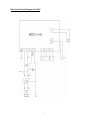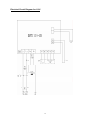
1
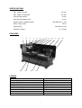
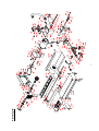
Code 505100
C0 Metal Turning
Lathe
IMPORATANT SAFETY INSTRUCTION
READ ALL INSTRUCTIONS AND WARNINGS BEFORE USING THIS TOOL
Operator
PLEASE REMEMBER:
1. When using electric tools, machines or equipment, basic safety precautions should always be
followed to reduce the risk of fire, electric shock, and personal injury.
2. Keep work area clean. Cluttered areas invite injuries.
3. Consider work area conditions. Do not use machines or power tools in damp, wet, or poorly lit
locations. Do not expose equipment to rain, keep work area well lit. Do not use tools in the
presence of flam-mable gases or liquids.
4. Keep children away, all children should be kept away from the work area.
5. Guard against electric shock. Prevent body contact with grounded surfaces such as pipes,
radiators, ranges, and refrig erator enclosures.
6. Stay alert. Never operate if you are tired.
7. Do not operate the product if under the influence of alcohol or drugs. Read warning labels on
prescriptions to determine if your judgment or reflexes might be impaired.
8. Do not wear loose clothing or jewelry as they can be caught in moving parts.
9. Wear restrictive hair covering to contain long hair.
10. Use eye and ear protection. Always wear.
11. Keep proper footing and balance at all times.
12. Do not reach over or across running machines.
Before operations
1. Be sure the switch is OFF when not in use and before plugging in.
2. Do not attempt to use inappropriate attachments in an attempt to exceed the tool”s capacity.
Approved accessories are available from the dealer or machine maker.
3. Check for damaged parts, before using any tool, any part that appears damaged should be
carefully checked to determine that it will operate properly and perform its intended function.
4. Check for alignment and binding of all moving parts, broken parts or mounting fixtures and
any other condition that may affect proper operation. Any part that is damaged should be prop
early repaired or replaced by a qualified technician.
5. Do not use the tool if any switch does not turn off and properly
Operation
1. Never force the tool or attachment to do the work of a larger industrial tool. It is designed to
do the job better and more safely at the rate for which it was intended.
2. Do not carry the tool by its power cord.
3. Always unplug the cord by the plug. Never yank the cord out of the wall.
4. Always turn off the machine before unplugging.
IF THERE IS ANY QUESTION ABOUT A CONDITION BEING SAFE OR UNSAFE, DO NOT
OPERATE THE TOOL!
Grounding Instructions
This machine has a three prong plug, the third prong is the ground. Plug this cord only into a
three-prong receptacle. Do not attempt to defeat the protection the ground wire provides by
cutting off the round prong. Cutting off the ground will result in a safety hazard and void the
warranty.
DO NOT MODIFY THE PLUG IN ANY WAY. IF YOU HAVE ANY DOUBT, CALL A QUALIFIED
ELECTRICIAN.
2
SPECIFICATIONS
Max. swing over bed
100 mm
Max. length of workpiece
125 mm
Hole through spindle
10 mm
Hole through tailstock quill
10 mm
100-3800 rpm ±10%
Spindle speed (Variable speed)
Motor output power
150 W
Packing size
500x400x310 mm
Net/Gross weight
13 / 22 kgs
FEATURES
1
14
2
15
3
4
16
5
6
7
8
9
10
11
12
13
17
LEGEND
1. Cover
3. Emergency Stop Switch
5. Power light
7. Chuck cover
9. DC motor
11. Tailstock casting
13. Handwheel
15. handlewheel
17. Leadscrew
2. Headstock
4. Variable speed control knob
6. Yellow light
8. 3-jaw chuck
10. Tool rest (optional)
12. Tailstock handlewheel
14. Base
16. Bedway
3
1. THE HEADSTOCK
The motor provides a direct drive to the spindle via an internal tooth type belt. Spindle speed is
variable, and is regulated by the Speed Control Knob(4). Located on the main control panel.
The 3-jaw self centering chuck(8) is mounted on the spindle flange. To remove the chuck, simply
remove the three securing nuts to rear of the flange allowing it to be pulled free together with
three mounting studs.
Note: The Chuck has a protection cover(7). Opening the cover, main power of the lathe will
be switched off, so keep closing the cover while running.
2. THE TAILSTOCK
The Tailstock Casting(11), may be moved along the bed to any desired position and is secured in
position by force of two screw (Front of the tailstock,) to lock or loose the wedge of the tailstock,
then you can remove or fix the tailstock casting.
3. THE SADDLE AND THE CROSS-SLIDE
The saddle carries the Cross-Slide, on to which is mounted the Tool Rest(10) allowing intricate
and delicate operations to be performed. It may be driven by a leadscrew, Via a Drive Nut, to
provide automatic feed when the Clutch(1) at the right position, is operated.
UNPACKING & PREPARING FOR USE
On receipt, carefully unpack the lathe, inspect to ensure that not damage was suffered in transit
and all parts are accounted for. Should any damage be apparent, or parts are missing, please
contact your dealer immediately.
With assistance, considering the weight of machine, raise it on to a good solid surface or
workbench. Proceed to remove all traces of preservative with paraffin or good quality solvent, and
lightly oil all machined surfaces.
Saddle, cross-slide and compound slide adjustments are all factory set to ensure smooth
movement in both directions. If however the adjustments have been upset during transit,
indicated by stiff or erratic movement, refer to ‘settings and adjustments’ for the methods of
adjustment.
All hex. Keys and spanners necessary to carry out various adjustments are supplied, together
with a chuck key for the 3-jaw chuck and a spare fuse. The fuse holder is located on the main
control panel.
The three external jaws for the 3-jaw self centering chuck. Extend the capacity of the chuck and
are discussed in greater detail under “Accessories”.
MOUNTING THE MACHINE
The machine should be mounted on a workbench, of sufficient height so that you do not need to bend
your back to perform normal operations.
Ensure the location is adequately lit and that youwill not be working in your own shadow.
STARTING PROCEDURE
A. DURING INSTALLATION-INITIAL START.
First put the lathe plug in the socket then release the Emergency Stop Switch (3), the power
lamp(5) lights.
4
Switch on the machine by GENTLY turning the Variable Speed control knob(4), clockwise. A
click will be heard as power is turned on, but the spindle will not rotate until the knob is turned
clockwise a little further. Speed will increase progressively the further the knob is turned.
Run of a total 5 minutes during which time gradually increase spindle speed to its maximum. Run
for at least 2 minutes at this speed before stopping the machine and disconnecting from the
mains supply.
Check that all components are still secure and working freely and correctly.
Check also to ensure the mountings are secure.
Should any adjustments be necessary, refer to the appropriate section under ‘Settings and
Adjustments’.
B. STARTING UNDER NORMAL CONDITIONS
1. Take all necessary precautions previously stated, and ensure the workpieces can rotate fully
without obstruction.
2. Proceed start the machine as described in Section A above.
3. If the machine is finished with or is to be left unattended, turn the Variable speed control knob
to the OFF position then disconnect from the mains supply.
ATTENTION: The power supply system of this machine has an automatic overload protective
device. If cutting or drilling too deep, the system will stop working, and a yellow lamp (6, on the
main panel) will light. Just turn off the Variable Speed control knob (4) and then turn on again.
The system will work again and the yellow lamp will go off automatically.
OPERATION
SIMPLE TURNING
Before starting the machine, as described above, it is imperative that the setup for the type of
work to be carried out is fully checked.
The following notes are guidelines as to how to set up the lathe in order to carry out a simple
turning operation.
ALWAYS plan your work. Have drawings or a plan on hand together with any measuring
instruments you may require, such as micrometers/ verniers / cailpers etc.
Select a cutting tool that will produce the desired cut and mount in the tool rest, with as little overhang as possible, securing it using three hex socket head screws. (ideally, the overhang should
be approx. , 6mm but not more than 8mm for a straight tool).
It is IMPORTANT to ensure that the tip of the cutting tool is on the center line of the work, or very
slightly below it. On no account should it be above the center line.
Where necessary shims should be used beneath the tool in order to achieve the correct height, or,
if the tip is too high, the only recourse is to select another tool or grind down the tip.
To check the tip is at the correct height, position the tool so that the tip is almost touching the
point of the tailstock center. They should coincide. If necessary make adjustments using shims,
grind down the cutting tip or select another tool.
If the tailstock is not to be used, you may remove it completely by slackening off the securing nut
at its base, and sliding it free of the bed.
5
Mark the surface of the work at the point where the cut is to end, i.e. the shoulder, using a scriber
or similar means, and move the saddle so that the cutting tool is directly opposite the mark, then
wind in the cross-slide so that the tool touches the surface of the work.
Whilst carrying out these manovres, rotate the chuck by hand to ensure that nothing will come
into contact with if when turning takes place, i.e. there is adequate clearance between the saddle ,
cross-slide, tool post or cutting tool, and the chuck.
When satisfied retract the cutting tool and wind the saddle away from the headstock, then wind
the cutting tool up to the work, somewhere along the length to be cut, whilst rotating the work by
hand, using the chuck.
Continue to advance the cutting tool slowly,
until it just touches the surface. Record this
position by zeroing the scale on the crossslide, i.e. turn the moveable scale until the
tool is a short distance from the right hand
edge of the work. Wind in the cross-slide
again one full until the zero marks again
coincide.
IMPORTANT: If you go past the zero marks,
back off again at least one half of a turn, then slowly bring the marks back together.
Whenever you use the scale, as an indicator, to advance the cross-slide or compound slide.
ALWAYS use this procedure to alight the marks. This is to take into.
Continue to turn the handle an amount equivalent to your desired depth of cut.
NOTE: We recommend that for rough cutting, you do not exceed 0.010”(0.25mm) as your
depth of cut.
The setup is now complete to begin your cutting operation, but before starting, check the position
of the Clutch for changing the manual & auto feeding set to left ( a hand).
Switch the machine ON as described under ‘Starting Procedure’ and slowly feed the cutting tool
into the work using the manual feed handle. Proceed until you reach the previously marked line
on the work, then retract the tool one or two complete turns on the Cross-slide feed handle.
Wind the saddle back to the beginning then wind the tool the same number of turns “in”, plus the
depth of desired cut, and proceed to cut once more.
NOTE: this describes the procedure for general, rough cutting. For other types of cuts-finishing,
cutting shoulders etc., you should consult a suitable handbook.
IMPORTANT: Your left hand should always be free in order to hit the emergency stop
should it become necessary.
MAINTENANCE
For maximum performance, it is essential that the lathe is properly maintained.
BEFORE USE
Always inspect before use. Any damage should be repaired and maladjustments rectified.
Damage to machined surfaces should be repaired with an oil stone. Test by hand to ensure
smooth operation of all parts before use.
Inject a few drops of oil to the oilways at both leadscrew bearing (each end bracket once outwice
during the day if used continuously.
Inject a few drops also to the compound slide oil way, located on the slide top surface, between
the two hex socket head screws.
AFTER USE
Remove all swarf from the machine and thoroughly clean all surfaces. If coolant has been used,
ensure it has completely drained from the tray.
6
Components should be dry, and all machined surfaces should be lightly oiled.
Always removed cutting tools, and store in a safe place.
MOTOR BRUSHES
The motor brushes may be changed by unscrewing the caps, at the upper of the motor, beneath
the headstock.
SETTINGS AND ADJUSTMENTS
Occasionally, it may be necessary to readjust various components in order to maintain optimum
performance. The adjustments that may be performed are as follows:
A. CROSS-SLIDE ADJUSTMENTS
The cross-slide is mounted on a dovetail slide, as shown below. Between the sloping surfaces on
one side of the dovetail, a “jib strip” is inserted, which may be tightened against the dovetail under
the influence of three adjuster, or “jib” screws, mounted along it’s length.
The jib screws are to be found on the right hand side of the slide, directly beneath the compound
slide handle. In time, wear will occur on the mating surfaces resulting in a “sloppiness” of action.
To adjust the jib strip, account for wear and ensure the slide moves evenly and smoothly,
proceed as follows:
1. Slacken off all lock nuts and screw in the jib screws evenly,
i.e. use the same torque for each screw. The slide should be
held firmly. Test by trying to turn the handle, but do not force
it.
2. Screw out each jib screw by one quarter of a turn only, and
nip up the lock nuts.
3. Test again, by turning the handle, the movement should be
even and smooth along its complete length.
4. If the movement is too slack, screw all adjusters “in” by one eighth of a turn, and re-try.
Similarly, if the movement is too stiff, screw “out” the adjusters by one eighth of a turn until the
correct adjustment is attained.
5. Tighten all lock nuts taking care to ensure you do not move the jib screws whilst doing so.
6. When completed, retract the slide fully and apply oil to all mating surfaces and the feed screw
thread, then wind the slid back to its normal position.
B. TAILSTOCK ADJUSTMENTS
The tailstock locked by one lock screw, if loose the lock screw the tailstock can moved to left or
right, when lock the lock screw(front the tailstock) then the it can fixed any position on the bed
way.
NOTE:
It is important that the cross-slide and compound slide adjustments are correctly out and that
there is no “sloppiness” of action. Any maladjustment will have a serious effect on the quality of
your work, as they will all be transferred to the tool tip. It is vital that there is as little movement of
the tool as possible.
ACCESSORIES
A range of accessories is available from your versatility of your machine. These are as follows:
NOTE: The accessories is “Optional accessories”, you can buy it from your dealer or the
factory.
7
Parts Diagram
8
Parts List ( I )
Item
1
2
3
4
5
6
7
8
9
10
11
12
13
14
15
16
17
18
19
20
21
22
23
24
25
26
27
28
29
30
31
32
33
34
35
36
37
38
39
40
41
42
43
44
45
46
47
48
49
50
Part name
Bed way
Leadscrew left support
Screw M6*14
Protective cover for
leadscrew
Screw M4*6
Screw ST2.9*6.5
Screw M3*8
PC Board
Electricity fixed plate
Screw M6*12
Rubber pad
Nut M6
Small washer 6
Switch label
lock connect
Power line
Base
Nut M4
Spring washer 4
Screw M4*10
leadscrew
Leadscrew right support
Handle wheel
Cap nut M5
Rotate small handle
Handle screw
Screw M4*6
Flat washer 4
Dust guard
3 jaw chuck
Spindle
Bearing 17*35*10
check ring 35
Screw M6*40
Fixed support
Screw M4*8
Check ring 17
V pulley
Adjust ring
Washer
Headstock
Pulley cover
Nut M4
Washer 4
Screw M4*8
Higne 38*31
Check ring 8
V belt
V pulley
Spring washer 6
Qty.
1
1
10
Item
51
52
53
Part name
Screw M5*20
Small washer 5
Nut M5
Qty.
2
2
2
1
54
Motor connect plate
1
1
3
4
1
1
6
4
6
10
1
2
1
1
5
7
3
1
1
3
3
3
3
9
4
1
1
1
2
2
3
1
2
1
1
1
1
1
1
4
4
6
2
2
1
1
4
55
56
57
58
Washer 5
Screw M5*14
key 3*16
DC Motor
Mat plate
Screw ST2.9*9.5
Electric box cover
Emergency stop button
Variable speed control knob
Yellow lamp
Green lamp
Variable speed control
Fuse box
plastic tube
Screw M4*8
protective cover for chuck
Rotate shaft
key 3*6
Spacer
Compress spring L=16
Screw M2*20
Micro switch
Nut M2
Electric box
Knife rest
Screw M4*6
Screw M6*35
Tailstock shaft
Screw M6*16
Set screw
Set screw M6*8
Tailstock shaft leadscrew
Small handle
Nesting
baffle
Tailstock
Screw M5*8
Screw M4*16
Saddle nut
Leadscrew
Saddle nut
Small washer 4
Screw M4*10
Nut support
Bolt M4*10
Washer 4
3
3
1
1
1
4
1
1
1
1
1
1
1
1
2
1
1
1
1
1
2
1
2
1
1
1
1
1
1
1
1
1
2
1
1
1
1
2
1
1
1
4
4
1
4
2
60
61
62
63
64
65
66
67
68
69
70
71
72
73
74
75
76
77
78
79
80
81
82
83
84
85
86
87
88
89
90
91
92
93
94
95
97
98
99
100
101
9
Parts List (II)
Item
102
103A
104
105
106
107
108
109
110
Part name
Leadscrew nut
Saddle
Screw M6*20
Saddle wedge
middle saddle
Rest nut
Main label
baffle
Screw M5*10
Qty.
1
1
1
1
1
1
1
1
1
Item
116
117
118
119
120
121
122
123
Part name
Baffle
Screw ST 2.9*6.5
Filter
Porcelain
Cap screw M4*14
Support
Press plate
Set screw M4*6
Qty.
1
2
1
1
2
1
2
4
Packing List
No.
Descriptions
Q’ty
1
Micro Lathe
1
2
L Hex. Wrench S:3, 4, 5
Each 1
3
Double end wrench 5.5*7
1
4
Fuse
1
5
Screw Driver
1
6
Instruction Manual
1
10
Remarks
Electrical Circuit Diagram for 230V
11
Electrical Circuit Diagram for 110V
12
Please dispose of packaging for the product in a responsible manner. It is suitable for recycling. Help to
protect the environment, take the packaging to the local recycling centre and place into the appropriate
recycling bin.
Only for EU countries
Do not dispose of electric tools together with household waste material. In observance of European
Directive 2002/96/EC on waste electrical and electronic equipment and itsimplementation in accordance
with national law, electric tools that have reached the end of their life must be collected separately and
returned to an environmentally compatible recycling facility.
Axminster Tool Centre,
Unit 10 Weycroft Avenue, Axminster, Devon EX13 5PH
axminster.co.uk