1
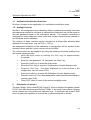
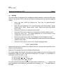
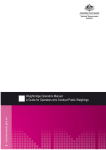
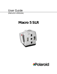
S457
14 January 2011
Bradfield Road, West Lindfield NSW 2070
Notification of Change
Supplementary Certificate of Approval No S457
Change No 1
Issued by the Chief Metrologist under Regulation 60
of the
National Measurement Regulations 1999
The following changes are made to the approval documentation for the
Avery Weigh-Tronix Model E1010 Digital Indicator
submitted by
Avery Weigh-Tronix Ltd
Foundry Lane
Smethwick
West Midlands B66 2LP
UK.
A.
In Supplementary Certificate of Approval No S457 dated 23 June 2005;
1.
The Condition of Approval referring to the review of the approval should be
amended to read:
“This approval becomes subject to review on 1 July 2015, and
then every 5 years thereafter.”
2.
The FILING ADVICE should be amended by adding the following:
“Notification of Change No 1 dated 14 January 2011”
Signed by a person authorised by the Chief Metrologist
to exercise his powers under Regulation 60 of the
National Measurement Regulations 1999.
S457
23 June 2005
12 Lyonpark Road, North Ryde NSW 2113
Supplementary Certificate of Approval
No S457
Issued by the Chief Metrologist under Regulation 60
of the
National Measurement Regulations 1999
This is to certify that an approval for use for trade has been granted in respect of the
Avery Weigh-Tronix Model E1010 Digital Indicator
submitted by
Avery Weigh-Tronix Ltd
Foundry Lane
Smethwick
West Midlands
B66 2LP
UK.
NOTE: This Certificate relates to the suitability of the pattern of the instrument for
use for trade only in respect of its metrological characteristics. This Certificate does
not constitute or imply any guarantee of compliance by the manufacturer or any other
person with any requirements regarding safety.
CONDITIONS OF APPROVAL
This approval becomes subject to review on 1 July 2010, and then every 5 years
thereafter.
Instruments purporting to comply with this approval shall be marked with approval
number ‘NMI S457’ and only by persons authorised by the submittor.
..../2
S457
23 June 2005
Supplementary Certificate of Approval No S457
Page 2
Instruments incorporating a component purporting to comply with this approval shall
be marked ‘NMI S457’ in addition to the approval number of the instrument.
It is the submittor’s responsibility to ensure that all instruments marked with this
approval number are constructed as described in the documentation lodged with the
National Measurement Institute (NMI) and with the relevant Certificate of Approval
and Technical Schedule. Failure to comply with this Condition may attract penalties
under Section 19B of the National Measurement Act and may result in cancellation or
withdrawal of the approval, in accordance with document NMI P 106.
The National Measurement Institute reserves the right to examine any instrument or
component of an instrument purporting to comply with this approval.
Auxiliary devices used with this instrument shall comply with the requirements of
General Supplementary Certificate No S1/0/A.
The values of the performance criteria (maximum number of scale intervals etc.)
applicable to an instrument incorporating the pattern approved herein shall be within
the limits specified herein and in any approval documentation for the other components.
DESCRIPTIVE ADVICE
Pattern: approved 17 June 2005
•
An Avery Weigh-Tronix model E1010 digital mass indicator.
Variant:
1.
approved 17 June 2005
An Avery Weigh-Tronix model E1005 digital mass indicator.
Technical Schedule No S457 describes the pattern and variant 1.
FILING ADVICE
The documentation for this approval comprises:
Supplementary Certificate of Approval No S457 dated 23 June 2005
Technical Schedule No S457 dated 23 June 2005 (incl. Table 1 and Test
Procedure)
Figures 1 and 2 dated 23 June 2005
Signed by a person authorised by the Chief Metrologist
to exercise his powers under Regulation 60 of the
National Measurement Regulations 1999.
S457
23 June 2005
TECHNICAL SCHEDULE No S457
Pattern:
Avery Weigh-Tronix Model E1010 Digital Indicator
Submittor:
Avery Weigh-Tronix Ltd
Foundry Lane
Smethwick
West Midlands
B66 2LP
1.
UK
Description of Pattern
An Avery Weigh-Tronix model E1010 digital mass indicator (Table 1 and Figure 1)
which is of stainless steel housing construction and which may be configured to form
part of:
•
A weighing instrument with a single weighing range of up to 10 000 verification
scale intervals; or
•
A multi-interval weighing instrument with up to two partial weighing ranges
(each with its own verification scale interval) in which case it is approved for
use with up to 5000 verification scale intervals per partial weighing range.
Instruments may be fitted with output sockets (output interfacing capability) for the
connection of auxiliary and/or peripheral devices.
Instruments are powered directly by mains AC power adaptor, or by an internal
rechargeable battery.
This approval does not include the use of the indicator as an automatic weighing
instrument, unless specifically mentioned in a certificate of approval for such an
instrument.
TABLE 1 – Specifications
Maximum number of verification scale intervals
Minimum sensitivity
Excitation voltage
Maximum excitation current
10 000 or 5000 per range
0.5 µV / scale interval
5 V DC
57.5 mA
1.1 Zero
Zero is automatically corrected to within ±0.25e whenever the instrument comes to
rest within 0.5e of zero
The instrument has a semi-automatic zero setting device (to set the instrument to
within ±0.25e of zero) with a nominal range of not more than 4% of the maximum
capacity of the instrument.
1.2 Tare
A semi-automatic subtractive taring device of up to the maximum capacity of the
instrument may be fitted. A pre-set taring device (keyboard-entered and/or stored) of
up to the maximum capacity (or of up to the Max1 (the maximum capacity of the lower
interval range) for multi-interval instruments) may also be fitted.
..../2
S457
23 June 2005
Technical Schedule No S457
Page 2
1.3 Display Check
A display check is initiated whenever power is applied.
1.4 Linearisation Facility
Instruments are fitted with a programmable multi-point linearisation correction facility.
1.5 Additional Features
The indicator may also have certain additional functions including setpoints (‘cutoffs’) and ‘under/accept/over’ functions. Some functions can be assigned to a function
key of the indicator. However, this approval does not include the use of the indicator
as an automatic weighing instrument, unless specifically mentioned in a certificate of
approval for such an instrument.
The additional functions (other than the indications of measured mass, i.e. gross,
tare, net, totals, displayed either on the indicator or on an auxiliary or peripheral
device) are not approved for trade use.
1.6 Markings and Notices
Instruments carry the following markings:
Manufacturer’s mark, or name written in full
Avery Weigh-Tronix Ltd
Name or mark of manufacturer’s agent
………..
Indication of accuracy class
Maximum capacity
Max….… kg
#1
Minimum capacity
Min…….. kg
#1
Verification scale interval
e = …….. kg
#1
Maximum subtractive tare
T = - …... kg
#2
Serial number of the instrument
………..
Pattern approval mark for the indicator
NMI S457
Pattern approval mark for other components
………..
#3
#1
These markings are also shown near the display of the result if they
are not already located there.
#2
This marking is required if T is not equal to Max.
#3
May be located separately from the other markings.
In addition, instruments not greater than 100 kg capacity shall carry a notice stating
NOT TO BE USED FOR TRADING DIRECT WITH THE PUBLIC, or similar wording.
Note:
For multi-interval instruments the markings shall be as above, with the exception that
the ‘Maximum capacity’ and ‘Verification scale interval’ shall be marked for both interval
ranges, e.g. as follows:
Maximum capacity
Max ...../..... kg
#1
Verification scale interval
e = ....../...... kg
#1
..../3
S457
23 June 2005
Technical Schedule No S457
Page 3
1.7 Verification/Certification Provision
Provision is made for the application of a verification/certification mark.
1.8 Sealing Provision
Access to the configuration and calibration facility is password protected (note that
the passwords required to configure or calibrate the instrument are not the same as
the user password shown in the instructions below). The indicator increments a
configuration and/or calibration value (audit trail number) each time the indicator is
re-configured and/or calibrated.
The value(s) of these counters may be recorded on a destructible adhesive label
attached to the instrument (e.g. as CFG x , CAL y).
Any subsequent alteration to the calibration or configuration will be evident as the
recorded values and the current counter values will differ.
The current value can be displayed by using the following sequence (starting from
the normal weighing mode):
2.
•
enter the user mode by holding the ‘Esc’ key for approximately
5 seconds.
•
Enter the user password ‘111’ and press the ‘Enter’ key.
•
Press the ‘Units’ key to enter the Audit mode.
•
Press the ‘Print’ key to enter the Configuration Counter display mode.
•
Press the ‘Print’ key. The value displayed for a short period is the
configuration counter value (CFG).
•
Press the ‘Units’ key to enter the Calibration Counter display mode.
•
Press the ‘Print’ key. The value displayed for a short period is the calibration
counter value (CAL).
•
Press ‘ESC’ twice to return to the normal weighing mode.
Description of Variant 1
The Avery Weigh-Tronix model E1005 (Figure 2), which is similar to the pattern (model
E1010), and has the same specifications (Table 1), but which has a plastic housing
and a reduced set of functions and operator keys. In particular the model E1005
does not have the capability for pre-set tare (keyboard-entered or stored).
..../4
S457
23 June 2005
Technical Schedule No S457
Page 4
2.1 Sealing
The instructions for accessing the configuration and calibration audit trail differ from
those of the model E1010, and are as follows (starting from the normal weighing
mode):
•
•
•
•
•
•
•
•
enter the user mode by holding the ‘Zero’ key for approximately
5 seconds.
Enter the user password ‘111’ by the following set of keystrokes – press
‘Select’ twice, ‘Units’, ‘Select’ twice, ‘Units’, ‘Select’ twice and then press
the ‘F1’ key.
Press the ‘Units’ key to enter the Audit mode.
Press the ‘Print’ key to enter the Configuration Counter display mode.
Press the ‘Print’ key. The value displayed for a short period is the
configuration counter value (CFG).
Press the ‘Units’ key to enter the Calibration Counter display mode.
Press the ‘Print’ key. The value displayed for a short period is the calibration
counter value (CAL).
Press the ‘Zero’ key to return to the normal weighing mode.
TEST PROCEDURE
Instruments should be tested in accordance with any relevant tests specified in the
Uniform Test Procedures.
Maximum Permissible Errors at Verification/Certification
For single range instruments, the maximum permissible errors for increasing and
decreasing loads on initial verification/certification for loads, m, expressed in
verification scale intervals, e, are:
± 0.5e for loads 0 < m < 500;
± 1.0e for loads 500 < m < 2 000; and
± 1.5e for loads 2 000 < m < 10 000.
For multi-interval instruments with verification scale intervals of e1, e2 …, apply e1 for
zero adjustment, and maximum permissible errors apply e1, e2 …, as applicable for
the load.
S457
23 June 2005
FIGURE S457 – 1
Avery Weigh-Tronix Model E1010 Digital Indicator
S457
23 June 2005
FIGURE S457 – 2
Avery Weigh-Tronix Model E1005 Digital Indicator