1
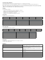
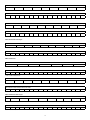
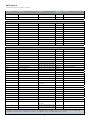
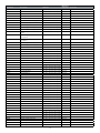
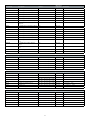
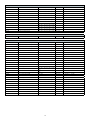
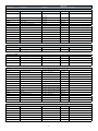
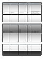
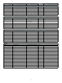
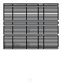
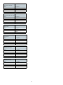
pw392
Communication Protocol
www.barco.com
Table of Contents
Setting up LAN communication.............................................................................................................................4
Connecting to the projector...................................................................................................................................4
Setting up RS232 communication.........................................................................................................................5
Connect to the projector.................................................................................................................................................... 5
RS232 Communication parameters................................................................................................................................... 5
Communication Protocol.......................................................................................................................................6
Timing..................................................................................................................................................................6
Overview............................................................................................................................................................................ 6
Message body.....................................................................................................................................................6
Mnemonic............................................................................................................................................................6
Modifiers..............................................................................................................................................................6
Acknowledge/Response.......................................................................................................................................7
Examples........................................................................................................................................................................... 7
ASCII protocol......................................................................................................................................................9
Value tables........................................................................................................................................................17
2
This page is Intentionally left blank
3
Setting up LAN communication
The projector is shipped with a set of default settings, these are as follows:
Description
Value
DHCP
On
IP address
0.0.0.0
Subnet mask
0.0.0.0
Default gateway
0.0.0.0
TCP/UDP port
1025
Username
admin
Password
admin
Before you connect the projector to your LAN make sure that the IP settings are set correct according to your LAN configuration.
IP settings can be changed from menu system or from the projector webpage. It can be set automatically by using DHCP (Dynamic
Host Configuration Protocol) or manually by disabling DHCP and set IP address, Subnet mask and Gateway.
Use of DHCP requires a DHCP server in the network.
When enabling DHCP please allow up to a minute for the projector to receive IP settings from the DHCP server. The IP address will be
updated and shown in the menu system.
Connecting to the projector
You have two options regarding how to make the physical connection to the projector. You can either use a crossover twisted pair (TP)
cable directly from the computer to the projector, or two straight-through TP cables with a HUB or a switch between them.
When the projector is set up with proper IP settings, you should be able to control it.
To verify the communication you can connect to the projector webpage. This is done by starting up an internet browser, like Internet
Explorer, Opera, Firefox or similar. Then type the projectors IP address (found in the projector network menu) in the address bar.
You will then see a login screen, see Figure 1.
Figure 1 : Login
Type in the projectors default login name (admin) and password (admin), both are case sensitive. If both are correct, you will se a
configuration website, see Figure 2.
4
Figure 2 : Web page
On this page you can setup the projectors IP address, subnet mask, default gateway, projector port (TCP/UDP) and password. This
page also displays the current version of network firmware the projector is running.
Setting up RS232 communication
Connect to the projector
Connect the projector and host using a standard serial cable with 9-pin female to the host, and 9-pin male to the projector. Pin 2
connects to pin 2, pin 3 connects to pin 3 and pin 5 connects to pin 5.
RS232 Communication parameters
Table 1 shows supported rs232 settings:
Parameter
Data
Baud rate
4800, 9600, 19200
Parity
N
Databits
8
Stopbits
1
Flowcontrol
None
Table 1: RS232 parameters
Baud rate is configurable from the projector’s menu system. Default baud rate is 19200.
5
Communication Protocol
This section describes how to use the communication protocol to control projectors remotely.
When the projects are connected to either RS232 or LAN you can control the projectors through this ASCII based protocol.
Note: Some commands will generate OSD feedback. This can be turned off from the projector’s menu system or by setting
“OSDC” to value 0 (OSD off) or value 1 (OSD show only warnings).
Timing
General timing constraints:
• Wait 30 seconds after power on before sending next command.
• Wait for response before sending next command.
• Minimum 2 seconds delay before resending if no response received.
• Minimum 500ms delay between commands.
• Minimum 5 seconds delay after sending 20 commands
Overview
The protocol has the following definition:
HEADER
SEPARATOR
ADDRESS
SEPARATOR
MESSAGE BODY
TERMINATOR
1 byte
1 byte
1 -3 bytes
1 byte
N bytes
1 byte
Field
Description
Comment
Header
ASCII character ‘:’
Required
Separator
ASCII character ‘space’
Optional
Address
1 – 3 bytes address
Optional
Terminator
CR carriage return (0x0D)
Required
Message body
The message body structure is as follows:
MNEMONIC
SEPARATOR]
MODIFIER
SEPARATOR
VALUES
SEPARATOR
TARGET
1 byte
1 byte
1 -3 bytes
1 byte
N bytes
1 byte
N bytes
Field
Description
Comment
Mnemonic
4 bytes key identifier, not case sensitive
Required
Modifer
Single char symbol
Optional
Values
N bytes value (max 6 bytes)
Optional
Target
N bytes value (max 4 bytes)
Optional
Separator
ASCII character ‘space’
Optional
Mnemonic
The Mnemonic is 4 bytes key identifier, know as the ASCII command.
Example: POWR, SABS, IVGA
Modifiers
R
Relative change. Value given will be relative to the existing value.
Example: :BRIG R10 will increase brightness with 10 steps
A
Request acknowledges. This modifier is only used to read back
the result of the command.
Default all commands send acknowledges so this will not be
necessary.
Default all commands send acknowledges so this will not be
necessary.
?
Get current value
?M
Get maximum value
?N
Get minimum value
?D
Get default value
?S
Get default step value
6
Acknowledge/Response
Acknowledge is optional and ON by default. Auto acknowledge can be turned on and off with ECHO commad. It can also be activated
on a per command basis using modifier A.
ACK
ADDRESS
SEP
COMMAND
SEP
VALUE
TERM
1 byte
3 bytes
1 byte
4 bytes
1 byte
6 bytes
1 byte
Field
Description
Comment
ACK
ASCII character ‘%’
Always
SEP
ASCII space
Always
VALUE
6 bytes return value
Always
TERM
Termination char 0x0D (CR)
Always
Most commands value returns the actual value of the requested command. If the requested command is not valid the response may
include an error message.
Code
Error message
Description
!00001
Access denied
Current access level is too low
!00002
Not available
Command currently not available.
Ex. contrast is not available when the
projector is searching
!00003
Not implemented
Command to implemented
!00004
Value out of range
Value out of range
Some commands could return a value that is more than 6 characters, for instance strings.
Code
Extended info
Description
e00001
Extended info, string
A description string follows
Example:
> :seri ?
> %001 SERI e00001 07010001
Examples
The protocol accepts one single SPACE between fields, or no SPACE between fields.
‘CR’ ASCII value carriage return, hex value 0x0D.
SET-commands
SET POWER ON
:
P
O
W
R
1
‘CR’
:POWR1’CR’
ACKNOWLEDGE POWER ON
%
0
0
1
P
O
W
R
0
0
0
0
0
1
‘CR’
%001 POWR 000001’CR’
SET BRIGHTNESS TO 60
:
B
R
I
G
6
0
‘CR’
:BRIG 60’CR’
ACKNOWLEDGE BRIGHTNESS
%
0
0
1
B
R
I
G
%001 BRIG 000060’CR’
7
0
0
0
0
6
0
‘CR’
INCREMENT CONTRAST
:
C
N
T
R
R
1
‘CR’
:CNTR R1’CR’
ACKNOWLEDGE INCREMENT CONTRAST
%
0
0
1
C
N
T
R
0
0
0
0
6
1
‘CR’
%001 CNTR 000061’CR’
DECREMENT CONTRAST with 2 steps
:
C
N
T
R
R
-
2
‘CR’
:CNTR R-2’CR’
ACKNOWLEDGE INCREMENT CONTRAST
%
0
0
1
C
N
T
R
0
0
0
0
5
9
‘CR’
%001 CNTR 000059’CR’
SET-commands with target
ENABLE CUSTOM PROFILE number 2
P
C
E
N
1
2
‘CR’
:PCEN 1 2’CR’
ACKNOWLEDGE ENABLE CUSTOM PROFILE
%
0
0
1
P
C
E
N
0
0
0
0
0
1
‘CR’
%001 PCEN 000001’CR’
GET-commands
GET current value CONTRAST
:
C
N
T
R
?
‘CR’
:CNTR?’CR’
ACKNOWLEDGE CONTRAST GET
%
0
0
1
C
N
T
R
0
0
0
0
5
9
‘CR’
%001 CNTR 000059’CR’
GET minimun value BRIGHTNESS
:
B
R
I
G
?
N
‘CR’
:BRIG ?N’CR’
ACKNOWLEDGE BRIGHTNESS GET MIN
%
0
0
1
B
R
I
G
0
0
0
0
0
0
‘CR’
%001 CNTR 000000’CR’
GET-commands with target
GET PROFILE CUSTOM CONNECTOR number 2
%
P
C
C
O
?
2
‘CR’
: PCCO ? 2
ACKNOWLEDGE GET PROFILE CUSTOM CONNECTOR
%
0
0
1
P
C
C
O
%001 PCCO 000003 ’CR’
8
0
0
0
0
0
3
‘CR’
ASCII protocol
Showing all properties for available commands.
Command
Description
Platforms*
Operations
supported
Comments
POWR
Power
GP1, GP2, GP3, GP4, GP1_AS3D
Get, Set
0 - power off, 1 - power on
POST
Power state
GP1, GP2, GP3, GP4, GP1_AS3D
Get
See value table POST
IABS
Set source abs values
GP1, GP2, GP3, GP4, GP1_AS3D
Get, Set
See value table IABS
IVGA
Select VGA
GP1, GP2, GP3, GP4, GP1_AS3D
Get, Set
ISVI
Select S-video
GP1, GP2, GP3, GP4, GP1_AS3D
Get, Set
IDVI
Select DVI
GP1, GP2, GP3, GP4, GP1_AS3D
Get, Set
ICVI
Select Composite video
GP1, GP2, GP3, GP4, GP1_AS3D
Get, Set
IYPP
Select Component YPbPr
GP1, GP2, GP3, GP4, GP1_AS3D
Get, Set
IRGS
Select RGB video
GP1, GP2, GP3, GP4
Get, Set
IHDM
Select HDMI
GP1, GP2, GP3, GP4
Get, Set
IBNC
Select BNC
GP3, GP4
Get, Set
IXP2
Select source XP2
GP3, GP4
Get
ISTS
Signal Status
GP1, GP2, GP3, GP4, GP1_AS3D
Get
BRIG
Brightness
GP1, GP2, GP3, GP4, GP1_AS3D
Get, Set
CNTR
Contrast
GP1, GP2, GP3, GP4, GP1_AS3D
Get, Set
CSAT
Color
GP1, GP2, GP3, GP4, GP1_AS3D
Get, Set
VHUE
Hue Video
GP1, GP2, GP3, GP4, GP1_AS3D
Get, Set
SHRP
Sharpness
GP1, GP2, GP3, GP4, GP1_AS3D
Get, Set
PRST
Picture Reset
GP1, GP2, GP3, GP4, GP1_AS3D
Get, Set
AUTO
Auto
GP1, GP2, GP3, GP4, GP1_AS3D
Set
PMUT
Picture Mute
GP1, GP2, GP3, GP4, GP1_AS3D
Get, Set
0 - disable, 1 - enable
FRZE
Freeze Image
GP1, GP2, GP3, GP4, GP1_AS3D
Get, Set
0 - disable, 1 - enable
SABS
Set Scaling abs value
GP1, GP2, GP3, GP4, GP1_AS3D
Get, Set
See value table SABS
S1T1
Select Scaling 1:1
GP1, GP2, GP3, GP4, GP1_AS3D
Get, Set
S169
Select Scaling 16:9
GP1, GP2, GP3, GP4, GP1_AS3D
Get, Set
SS43
Select Scaling 4:3
GP1, GP2, GP3, GP4, GP1_AS3D
Get, Set
SFLA
Select Scaling FillAll
GP1, GP2, GP3, GP4, GP1_AS3D
Get, Set
SFAR
Select Scaling FillAspectRatio
GP1, GP2, GP3, GP4, GP1_AS3D
Get, Set
SLET
Select Scaling Letterbox to 16:9
GP1, GP2, GP3, GP4, GP1_AS3D
Get, Set
SLST
Select Scaling Letterbox St to 16:9
GP1, GP2, GP3, GP4, GP1_AS3D
Get, Set
SANL
Scale Anamorphic
GP1 1080, GP2 1080, GP3 1080,
GP4 1080
Get, Set
1-film 1, 2-film 2
SABS
Select Gamma Film
GP1, GP2, GP3, GP4, GP1_AS3D
Get, Set
1 - Film 1, 2 - Film 2
S1T1
Select Gamma Video
GP1, GP2, GP3, GP4, GP1_AS3D
Get, Set
1 - Video 1, 2 - Video2
S169
Select Gamma Computer
GP1, GP2, GP3, GP4, GP1_AS3D
Get, Set
1 - Computer 1, 2 - Computer 2
SS43
Set Gamma abs value
GP1, GP2, GP3, GP4, GP1_AS3D
Get, Set
See value table GABS
SFLA
Select Scaling FillAll
GP1, GP2, GP3, GP4, GP1_AS3D
Get, Set
See value table BCCR
SFAR
Select Scaling FillAspectRatio
GP1, GP2, GP3, GP4, GP1_AS3D
Get, Set
See value table BCCR
SLET
BrilliantColor Control
GP1, GP2, GP3, GP4, GP1_AS3D
Get, Set
See value table BCCR
SLST
BrilliantColor Mode
GP1, GP2, GP3, GP4, GP1_AS3D
Get, Set
See value table BCMO
SANL
BrilliantColor Look
GP1 1080, GP2 1080, GP3 1080,
GP4 1080
Get, Set
See value table BCPR
GAFI
Select Gamma Film
GP1, GP2, GP3, GP4, GP1_AS3D
Get, Set
1 - Film 1, 2 - Film 2
GAVI
Select Gamma Video
GP1, GP2, GP3, GP4, GP1_AS3D
Get, Set
1 - Video 1, 2 - Video2
Soure selection
0 - searching 1 - locked to source
Picture
*Supported commands for the various product platforms are marked GP1, GP2, and GP3. Typical Products are GP1 F10 sx+, F10 1080, F10
wuxga. GP2: F20 720, F20 sx+, F20 medical, evo 20 sx+ cineo 20. GP3: F30 sx+, F30 1080, F30 wuxga, cineo 30.
9
Command
Description
Platforms*
Operations
supported
Comments
GACO
Select Gamma Computer
GP1, GP2, GP3, GP4, GP1_AS3D
Get, Set
1 - Computer 1, 2 - Computer 2
GABS
Set Gamma abs value
GP1, GP2, GP3, GP4, GP1_AS3D
Get, Set
See value table GABS
BCCR
BrilliantColor Control
GP1, GP2, GP3
Get, Set
See value table BCCR
BCMO
BrilliantColor Mode
GP1, GP2, GP3
Get, Set
See value table BCMO
BCPR
BrilliantColor Look
GP1, GP2, GP3
Get, Set
See value table BCPR
See value table PRES
PRES
BrilliantColor Preset Settings
GP1
Get, Set
WPEK
BrilliantColor Boost
GP1, GP2, GP3
Get, Set
CMXV
Color Management X-Coordinate
GP1, GP2, GP3, GP4, GP1_AS3D
Get, Set
CMYV
Color Management Y-Coordinate
GP1, GP2, GP3, GP4, GP1_AS3D
Get, Set
CMTV
Color Management Temperature
GP1, GP2, GP3, GP4
Get, Set
CMNA
Color Management Mode Not Corrected
GP1, GP2, GP3, GP4, GP1_AS3D
Get, Set
CMTE
Color Management Mode Color
Temeperature
GP1, GP2, GP3, GP4, GP1_AS3D
Get, Set
CCXY
Color Management Mode Custom
Coordinates
GP1, GP2, GP3, GP4, GP1_AS3D
Get, Set
CMHS
Color Management Mode HSG
GP1
Get, Set
CMPR
Color Management Mode presets
GP1
3200 - 9300
RD65
Reset to D65
GP1, GP2, GP3, GP4, GP1_AS3D
Set
DSCR
Desired Coords Mode
GP1, GP2, GP3, GP4, GP1_AS3D
Get, Set
See value table DSCR
BAGA
Balance Gains Enable
GP1, GP2, GP3
Get, Set
0 - disable, 1 - enable
DSRX
Desired Red X
GP1, GP2, GP3, GP4, GP1_AS3D
Get, Set
DSRY
Desired Red Y
GP1, GP2, GP3, GP4, GP1_AS3D
Get, Set
DSRG
Desired Red Gain
GP1, GP2, GP3, GP4, GP1_AS3D
Get, Set
DSGX
Desired Green X
GP1, GP2, GP3, GP4, GP1_AS3D
Get, Set
DSGY
Desired Green Y
GP1, GP2, GP3, GP4, GP1_AS3D
Get, Set
DSGG
Desired Green Gain
GP1, GP2, GP3, GP4, GP1_AS3D
Get, Set
DSBX
Desired Blue X
GP1, GP2, GP3, GP4, GP1_AS3D
Get, Set
DSBY
Desired Blue Y
GP1, GP2, GP3, GP4, GP1_AS3D
Get, Set
DSBG
Desired Blue Gain
GP1, GP2, GP3, GP4, GP1_AS3D
Get, Set
DSCX
Desired Cyan X
GP1, GP2, GP3, GP4, GP1_AS3D
Get, Set
DSCY
Desired Cyan Y
GP1, GP2, GP3, GP4, GP1_AS3D
Get, Set
DSCG
Desired Cyan Gain
GP1, GP2, GP3, GP4, GP1_AS3D
Get, Set
DSMX
Desired Magenta X
GP1, GP2, GP3, GP4, GP1_AS3D
Get, Set
DSMY
Desired Magenta Y
GP1, GP2, GP3, GP4, GP1_AS3D
Get, Set
DSMG
Desired Magenta Gain
GP1, GP2, GP3, GP4, GP1_AS3D
Get, Set
DSYX
Desired Yellow X
GP1, GP2, GP3, GP4, GP1_AS3D
Get, Set
DSYY
Desired Yellow Y
GP1, GP2, GP3, GP4, GP1_AS3D
Get, Set
DSYG
Desired Yellow Gain
GP1, GP2, GP3, GP4, GP1_AS3D
Get, Set
DSWG
Desired White Gain
GP1, GP2, GP3, GP4, GP1_AS3D
Get, Set
MSRX
Measured Red X
GP1, GP2, GP3, GP4, GP1_AS3D
Get, Set
MSRY
Measured Red Y
GP1, GP2, GP3, GP4, GP1_AS3D
Get, Set
MSRL
Measured Red Luminance
GP1, GP2, GP3, GP4, GP1_AS3D
Get, Set
MSGX
Measured Green X
GP1, GP2, GP3, GP4, GP1_AS3D
Get, Set
MSGY
Measured Green Y
GP1, GP2, GP3, GP4, GP1_AS3D
Get, Set
MSGL
Measured Green Luminance
GP1, GP2, GP3, GP4, GP1_AS3D
Get, Set
MSBX
Measured Blue X
GP1, GP2, GP3, GP4, GP1_AS3D
Get, Set
MSBY
Measured Blue Y
GP1, GP2, GP3, GP4, GP1_AS3D
Get, Set
MSBL
Measured Blue Luminance
GP1, GP2, GP3, GP4, GP1_AS3D
Get, Set
MSWX
Measure White X
GP1, GP2, GP3, GP4, GP1_AS3D
Get, Set
MSWY
Measure White Y
GP1, GP2, GP3, GP4, GP1_AS3D
Get, Set
MSWL
Measure White Luminance
GP1, GP2, GP3, GP4, GP1_AS3D
Get, Set
CMHR
ColorMangement Hue Red
GP1
Get, Set
CMHG
ColorMangement Hue Green
GP1
Get, Set
CMHB
ColorMangement Hue Blue
GP1
Get, Set
10
Command
Description
Platforms*
Operations
supported
CMHC
ColorMangement Hue Cyan
GP1
Get, Set
CMHM
ColorMangement Hue Magenta
GP1
Get, Set
CMHY
ColorMangement Hue Yellow
GP1
Get, Set
CMSR
ColorMangement Saturation Red
GP1
Get, Set
CMSG
ColorMangement Saturation Green
GP1
Get, Set
CMSB
ColorMangement Saturation Blue
GP1
Get, Set
CMSC
ColorMangement Saturation Cyan
GP1
Get, Set
CMSM
ColorMangement Saturation
Magenta
GP1
Get, Set
CMSY
ColorMangement Saturation Yellow
GP1
Get, Set
CMGR
ColorMangement Gain Red
GP1
Get, Set
CMGG
ColorMangement Gain Green
GP1
Get, Set
CMGB
ColorMangement Gain Blue
GP1
Get, Set
CMGC
ColorMangement Gain Cyan
GP1
Get, Set
CMGM
ColorMangement Gain Magenta
GP1
Get, Set
CMGY
ColorMangement Gain Yellow
GP1
Get, Set
CMWR
ColorMangement White Balance
Red
GP1
Get, Set
CMWG
ColorMangement White Balance
Green
GP1
Get, Set
CMWB
ColorMangement White Balance
Blue
GP1
Get, Set
CMTP
Color Management Test Patterns
GP1, GP2, GP3, GP4, GP1_AS3D
Get, Set
CMTG
PW test patterns
GP1, GP2, GP3, GP4
Get, Set
Comments
See value table CMTG
Picture->RealColor->Display Customization
BRED
Red Offset
GP1, GP2, GP3, GP1_AS3D
Get, Set
BGRE
Green Offset
GP1, GP2, GP3, GP1_AS3D
Get, Set
BBLU
Blue Offset
GP1, GP2, GP3, GP1_AS3D
Get, Set
CRED
Red Gain
GP1, GP2, GP3, GP1_AS3D
Get, Set
CGRE
Green Gain
GP1, GP2, GP3, GP1_AS3D
Get, Set
CBLU
Blue Gain
GP1, GP2, GP3, GP1_AS3D
Get, Set
VPOS
Vertical Position
GP1, GP2, GP3, GP1_AS3D
Get, Set
HPOS
Horizontal Position
GP1, GP2, GP3, GP4, GP1_AS3D
Get, Set
PHSE
Phase
GP1, GP2, GP3, GP4, GP1_AS3D
Get, Set
FREQ
Frequency
GP1, GP2, GP3, GP4, GP1_AS3D
Get, Set
NIRE
IRE Setup
GP1, GP2, GP3, GP4, GP1_AS3D
Get, Set
DLSP
Digital Level and Colorspace
GP1, GP2, GP3, GP4, GP1_AS3D
Get, Set
0 - manual, 1 - auto
DVST
Digital Level
GP1, GP2, GP3, GP4, GP1_AS3D
Get, Set
0 - computer, 1 - video
DCSP
Digital Color Space
GP1, GP2, GP3, GP4, GP1_AS3D
Get, Set
See value tab DCPS
Picture->Advanced
Picture->Advanced ->Source Correction
AORD
AD Red Offset
GP1, GP2, GP3, GP4, GP1_AS3D
Get, Set
AOGR
AD Green Offset
GP1, GP2, GP3, GP4, GP1_AS3D
Get, Set
AOBL
AD Blue Offset
GP1, GP2, GP3, GP4, GP1_AS3D
Get, Set
AGRD
AD Red Gain
GP1, GP2, GP3, GP4, GP1_AS3D
Get, Set
AGGR
AD Green Gain
GP1, GP2, GP3, GP4, GP1_AS3D
Get, Set
AGBL
AD Blue Gain
GP1, GP2, GP3, GP4, GP1_AS3D
Get, Set
ACAL
AD calibration
GP1, GP2, GP3, GP4, GP1_AS3D
Set
11
Picture->Enhancements
DLTI
DLTI Level
GP1, GP2, GP3, GP4, GP1_AS3D
Get, Set
DCTI
DCTI Level
GP1, GP2, GP3, GP4, GP1_AS3D
Get, Set
CB3D
3D Comb Filter
GP1, GP2, GP3, GP4, GP1_AS3D
Get, Set
PK2D
2D Peaking
GP1, GP2, GP3, GP4, GP1_AS3D
Get, Set
ANOI
Adaptive Noise Reduction
GP1, GP2, GP3, GP4, GP1_AS3D
Get, Set
CEHR
CEH Red
GP1, GP2, GP3, GP4, GP1_AS3D
Get, Set
CEHB
CEH Blue
GP1, GP2, GP3, GP4, GP1_AS3D
Get, Set
CEHG
CEH Green
GP1, GP2, GP3, GP4, GP1_AS3D
Get, Set
CEHY
CEH Yellow
GP1, GP2, GP3, GP4, GP1_AS3D
Get, Set
CEHF
CEH Fleshtone
GP1, GP2, GP3, GP4, GP1_AS3D
Get, Set
DYNC
Dynamic Contrast Enable
GP1, GP2, GP3, GP4, GP1_AS3D
Get, Set
DYNL
Dynamic Contrast Level
GP1, GP2, GP3, GP4, GP1_AS3D
Get, Set
HDBL
Horizontal Deblocking
GP1, GP2, GP3, GP4, GP1_AS3D
Get, Set
Dynamic Black
GP4, GP3 LED
Get, Set
DESK
Select Orientation Desktop Front
GP1, GP2, GP3, GP4, GP1_AS3D
Get, Set
CEIL
Select Orientation Ceiling Front
GP1, GP2, GP3, GP4, GP1_AS3D
Get, Set
RDES
Select Orientation Desktop Rear
GP1, GP2, GP3, GP4, GP1_AS3D
Get, Set
RCEI
Select Orientation Ceiling Rear
GP1, GP2, GP3, GP4, GP1_AS3D
Get, Set
ORIE
Select Orientation abs value
GP1, GP2, GP3, GP4, GP1_AS3D
Get, Set
See value table ORIE
SCAN
Source Scan
GP1, GP2, GP3, GP4, GP1_AS3D
Get, Set
0 - disable, 1 - enable
VRGB
RGB video
GP1, GP2, GP3, GP4, GP1_AS3D
Get, Set
0 - disable, 1 - enable
BNCR
BNC colorspace RGB
GP3, GP4
Get, Set
BNCC
BNC colorspace YPbPr
GP3, GP4
Get, Set
IR01
IR Enable 1
GP1, GP2, GP3, GP4, GP1_AS3D
Get, Set
0 - disable, 1 - enable
IR02
IR Enable 2
GP1, GP2, GP3, GP4, GP1_AS3D
Get, Set
0 - disable, 1 - enable
IR03
IR Enable 3
GP3
Get, Set
0 - disable, 1 - enable
WIDE
Wide Setup
GP1, GP2, GP3, GP4, GP1_AS3D
Get, Set
0 - disable, 1 - enable
SVGA
Sync Termination VGA
GP1, GP2, GP3, GP4, GP1_AS3D
Get, Set
0 - disable, 1 - enable
SVG2
Sync Termination VGA 2
GP1
Get, Set
0 - disable, 1 - enable
SDVI
Sync Termination DVI-A
GP2
Get, Set
0 - disable, 1 - enable
SBNC
Sync Termination BNC
GP3, GP4
Get, Set
0 - disable, 1 - enable
OSDC
OSD Enable
GP1, GP2, GP3, GP4, GP1_AS3D
Get, Set
See value table OSDC
TEST
Test Image
GP1, GP2, GP3, GP4, GP1_AS3D
Get, Set
0 - 7 different test patterns
VKEY
Vertical Keystone
GP1, GP2, GP3, GP4, GP1_AS3D
Get, Set
SNCL
Sync Level
GP1, GP2, GP3, GP4, GP1_AS3D
Get, Set
Infitec only
SNCS
Sync Level RGB video
GP1, GP2, GP3, GP4
Get, Set
Infitec only
CSFI
Enable Color Space Convert
GP1, GP2, GP3, GP4, GP1_AS3D
Get, Set
Infitec only
OPFI
Enable Optical Filter
GP3, GP4
Get, Set
Infitec only
VFVE
Video filter VGA enable
GP3, GP4
Get, Set
0 - disable, 1 - enable
VFBE
Video filter BNC enable
GP3, GP4
Get, Set
0 - disable, 1 - enable
OPFA
Optical filter all
GP4
Get, Set
0 - disable, 1 - enable
Picture->Dynamic Black
DBEN
0 - disable, 1 - enable
Installation
12
Command
Description
Platforms*
Operations
supported
Comments
0 - disable, 1 - enable
Installation->lamp/LED
ECOM
Eco Mode
GP1, GP2, GP3, GP4, GP1_AS3D
Get, Set
LPW1
Lamp1 Power/LED Power
GP1, GP2, GP3, GP4, GP1_AS3D,
GP3 LED
Get, Set
LPW2
Lamp2 Power
GP3, GP4
Get, Set
DBDI
LED Power
GP3 LED
Get, Set
LMOD
Lamp Mode
GP3, GP4
Get, Set
LDLY
Lamp Auto Switch Delay
GP3, GP4
Get, Set
DUAL
Lamp Mode Dual
GP3, GP4
Get, Set
Use LMOD, this is for legacy support
SNGL
Lamp Mode Single
GP3, GP4
Get, Set
Use LMOD, this is for legacy support
LAUT
Lamp Mode Auto
GP3, GP4
Get, Set
Use LMOD, this is for legacy support
LACT
Select Lamp In Single Mode
GP3, GP4
Get, Set
Use LMOD, this is for legacy support
LDMM
LED Dim Mode
GP3 LED
Get, Set
0 - standard, 1 - custom
LDCR
Custom LED Dim Red
GP3 LED
Get, Set
0-20
LDCG
Custom LED Dim Green
GP3 LED
Get, Set
0-20
LDCB
Custom LED Dim Blue
GP3 LED
Get, Set
0-20
SMOD
Screen Trigger Mode
GP1, GP2, GP3, GP4, GP1_AS3D
Get, Set
See value table SMOD
AMOD
Aspect Trigger Mode
GP1, GP3, GP4, GP1_AS3D
Get, Set
See value table AMOD
EDIR
EDID resolution
GP1, GP2, GP3, GP4
Get, Set
See value table EDIR
EDIT
EDID type
GP1, GP2, GP3, GP4
Get, Set
See value table EDIT
EDMD
EDID Mailbox Data, auto increment
GP1, GP2, GP3, GP4
Get, Set
EDMR
EDID Mailbox Counter reset
GP1, GP2, GP3, GP4
Get, Set
FCRE
Factory Reset
GP1, GP2, GP3, GP4, GP1_AS3D
Set
FCRL
Factory reset level
GP1, GP2, GP3, GP4
Get, Set
PINC
PIN Code
GP1, GP2, GP3, GP4, GP1_AS3D
Set
CODE
Service Code
GP1, GP2, GP3, GP4, GP1_AS3D
Set
RCID
RCID Internal
GP1, GP2, GP3, GP4, GP1_AS3D
Get, Set
DPMS
DPMS
GP1, GP2, GP3, GP4, GP1_AS3D
Get, Set
DPMT
DPMS Timeout
GP1, GP2, GP3, GP4, GP1_AS3D
Get, Set
KEYB
Backlight Timeout
GP1, GP2, GP3, GP4, GP1_AS3D
Get, Set
MNUT
Menu Timeout
GP1, GP2, GP3, GP4, GP1_AS3D
Get, Set
BACK
Background color
GP1, GP2, GP3, GP4, GP1_AS3D
Get, Set
SPLH
Splash
GP1, GP2, GP3, GP4, GP1_AS3D
Get, Set
LMUT
LED indicators mute
GP1, GP2, GP3, GP4
Get, Set
BAUD
Baudrate
GP1, GP2, GP3, GP4, GP1_AS3D
Get, Set
ADRM
RS232 address mode
GP1, GP2, GP3, GP4
Get, Set
ADRF
RS232 fixed address
GP1, GP2, GP3, GP4
Get, Set
See value table LMOD
Installation->trigger
Installation->EDID
Settings
Settings->Set date and time
RTCH
Real Time Clock Hour
GP1, GP2, GP3, GP4, GP1_AS3D
Get, Set
RTCM
Real Time Clock Minute
GP1, GP2, GP3, GP4, GP1_AS3D
Get, Set
RTCS
Real Time Clock Second
GP1, GP2, GP3, GP4, GP1_AS3D
Get, Set
RTCD
Real Time Clock Day
GP1, GP2, GP3, GP4, GP1_AS3D
Get, Set
RTCN
Real Time Clock Month
GP1, GP2, GP3, GP4, GP1_AS3D
Get, Set
RTCY
Real Time Clock Year
GP1, GP2, GP3, GP4, GP1_AS3D
Get, Set
RTCW
Real Time Clock Day of Week
GP1, GP2, GP3, GP4
Get, Set
13
Must be run in standby
0 - disable, 1 - enable
See value table BAUD
Description
Platforms*
Operations
supported
UMST
Store User Settings
GP1, GP2, GP3, GP4, GP1_AS3D
Get, Set
UMRC
Recall User Settings
GP1, GP2, GP3, GP4, GP1_AS3D
Get, Set
STMO
Store motor position
GP4
Set
RCMO
Recall motor position
GP4
Set
PRMO
Profile Mode
GP1, GP2, GP3, GP4
Get, Set
0 - Auto, 1 - Custom, 2 - ISF
PIMO
Profile ISF Mode
GP1, GP2, GP3, GP4
Get, Set
0 - ISF Day, 1 - ISF Night
PCEN
Profile Custom Enable
GP1, GP2, GP3, GP4
Get, Set
Value: 0 - disable, 1 - enable
Target: Custom profile number (0 - 9)
PCNA
Profile Custom Name
GP1, GP2, GP3, GP4
Get, Set
Value: Profile name as string
Target: Custom profile number (0 - 9)
PCCO
Profile Custom Connector
GP1, GP2, GP3, GP4
Get
Value: Connector (see Profile Con List )
Target: Custom profile number (0 - 9)
PRCC
Profile Custom Current Profile
GP1, GP2, GP3, GP4
Get
PSTO
Profile Custom Store
GP1, GP2, GP3, GP4
Set
PCRC
Profile Custom Recall
GP1, GP2, GP3, GP4
Set
PRRC
Profile Custom Recall Current
GP1, GP2, GP3, GP4
Set
PRER
Profile Custom Erase
GP1, GP2, GP3, GP4
Set
See value table PRER
PRCH
Current Profile changed?
GP1, GP2, GP3, GP4
Get
Returns string * (asterisk) if changed
Command
Comments
Profiles
See value table PSTO
* User Settings is replaced by Profile in some software versions
Lens control
FOIN
Focus In
GP3, GP4
Set
1 - Slow, 2 - Medium, 3 - Fast
FOUT
Focus Out
GP3, GP4
Set
1 - Slow, 2 - Medium, 3 - Fast
ZOIN
Zoom In
GP3, GP4
Set
1 - Slow, 2 - Medium, 3 - Fast
ZOUT
Zoom Out
GP3, GP4
Set
1 - Slow, 2 - Medium, 3 - Fast
IROP
Iris Open
GP3, GP4
Set
1 - Slow, 2 - Medium, 3 - Fast
IRCL
Iris Close
GP3, GP4
Set
1 - Slow, 2 - Medium, 3 - Fast
LSDW
Lens Shift Down
GP3, GP4
Set
1 - Slow, 2 - Medium, 3 - Fast
LSUP
Lens Shift Up
GP3, GP4
Set
1 - Slow, 2 - Medium, 3 - Fast
LSLF
Lens Shift Left
GP3, GP4
Set
1 - Slow, 2 - Medium, 3 - Fast
LSRH
Lens Shift Right
GP3, GP4
Set
1 - Slow, 2 - Medium, 3 - Fast
SHUT
Shutter
GP3, GP4
Set
0 - disable, 1 - enable
ZOPO
Zoom Position
GP4
Get, Set
FOPO
Focus Position
GP4
Get, Set
HOPO
Horizontal Lensshift Position
GP4
Get, Set
VEPO
Vertical Lensshift Position
GP4
Get, Set
IRPO
Iris Position
GP4
Get, Set
LENS
Lens ID
GP3, GP4
Get
LMON
Lens Monitoring
GP3, GP4
Get, Set
* User Settings is replaced by Profile in some software versions
Lamp status
LRM1
Lamp1 Estimated Remaining Lamp
Time
GP1, GP2, GP3, GP4, GP1_AS3D
Get
LTR1
Lamp1 Runtime
GP1, GP2, GP3, GP4, GP1_AS3D
Get
LHO1
Lamp Channel 1 Total Time
GP3, GP4
Get
LST1
Lamp1 Status
GP1, GP2, GP3, GP4, GP1_AS3D
Get
LRM2
Lamp2 Estimated Remaining Lamp
Time
GP3, GP4
Get
LTR2
Lamp2 Runtime
GP3, GP4
Get
LHO2
Lamp Channel 2 Total Time
GP3, GP4
Get
LST2
Lamp2 Status
GP3, GP4
Get
UTOT
Unit Time Total
GP1, GP2, GP3, GP4, GP1_AS3D
Get
14
See value table LST1 and LST2
See value table LST1 and LST2
Description
Platforms*
Operations
supported
MENU
Menu Navigate Toggle OSD Menu
GP1, GP2, GP3, GP4, GP1_AS3D
Set
NVUP
Menu Navigate Up
GP1, GP2, GP3, GP4, GP1_AS3D
Set
NVDW
Menu Navigate Down
GP1, GP2, GP3, GP4, GP1_AS3D
Set
NVLF
Menu Navigate Left
GP1, GP2, GP3, GP4, GP1_AS3D
Set
NVRH
Menu Navigate Right
GP1, GP2, GP3, GP4, GP1_AS3D
Set
NVOK
Menu Navigate Ok
GP1, GP2, GP3, GP4, GP1_AS3D
Set
ECHO
Communication Response (on/off)
GP1, GP2, GP3, GP4, GP1_AS3D
Set
LANG
Language
GP1, GP2, GP3, GP4
Get, Set
OSDP
OSD Menu Position
GP1 Avielo, GP2 Avielo, GP3
Avielo, GP4 Avielo
Get, Set
0 - standard, 1 - anamorph
SNAM
Show OSD Projector ID
GP1, GP2, GP3, GP4
Set
Extended Protocol
SINF
Show OSD Info
GP1, GP2, GP3, GP4
Set
Extended Protocol
MESS
Show OSD Message
GP1, GP2, GP3, GP4
Get, Set
Extended Protocol
NAME
Projector ID
GP1, GP2, GP3, GP4
Get, Set
Extended Protocol
MDOF
Medical Off
GP2
Get, Set
medical only
MDCL
Medical Clearbase
GP2
Get, Set
medical only
MDBL
Medical Bluebase
GP2
Get, Set
medical only
MDFW
Medical Full White
GP2
Get, Set
medical only
MDCX
DICOM Clearbase x
GP2
Get, Set
medical only
MDCY
DICOM Clearbase y
GP2
Get, Set
medical only
MDBX
DICOM Bluebase x
GP2
Get, Set
medical only
MDBY
DICOM Bluebase y
GP2
Get, Set
medical only
THRM
Thermal Status
GP1, GP2, GP3, GP4, GP1_AS3D
Get
FAN1
Fan Speed 1
GP1, GP2, GP3, GP4, GP1_AS3D
Get
FAN2
Fan Speed 2
GP1, GP2, GP3, GP4, GP1_AS3D
Get
FAN3
Fan Speed 3
GP1, GP2, GP3, GP4, GP1_AS3D
Get
FAN4
Fan Speed 4
GP1, GP2, GP3, GP4, GP1_AS3D
Get
FAN5
Fan Speed 5
GP1, GP2, GP3, GP4, GP1_AS3D
Get
FAN6
Fan Speed 6
GP1, GP2, GP3, GP4, GP1_AS3D
Get
FAN7
Fan Speed 7
GP1, GP2, GP3, GP4, GP1_AS3D
Get
FAN8
Fan Speed 8
GP1, GP2, GP3, GP4, GP1_AS3D
Get
SNS1
Sensor Value 1
GP1, GP2, GP3, GP4, GP1_AS3D
Get
SNS2
Sensor Value 2
GP1, GP2, GP3, GP4, GP1_AS3D
Get
SNS3
Sensor Value 3
GP1, GP2, GP3, GP4, GP1_AS3D
Get
SNS4
Sensor Value 4
GP1, GP2, GP3, GP4, GP1_AS3D
Get
SNS5
Sensor Value 5
GP1, GP2, GP3, GP4, GP1_AS3D
Get
SNS6
Sensor Value 6
GP1, GP2, GP3, GP4, GP1_AS3D
Get
SNS7
Sensor Value 7
GP1, GP2, GP3, GP4, GP1_AS3D
Get
SNS8
Sensor Value 8
GP1, GP2, GP3, GP4, GP1_AS3D
Get
Command
Comments
Menu navigate
Miscellaneous
Medical
Thermal
15
Description
Platforms*
Operations
supported
Comments
PLAT
Platform Name String
GP1, GP2, GP3, GP4, GP1_AS3D
Get
Extended Protocol
SERI
Serial Number String
GP1, GP2, GP3, GP4, GP1_AS3D
Get
Extended Protocol
MODL
Model Name String
GP1, GP2, GP3, GP4, GP1_AS3D
Get
Extended Protocol
PART
Part Number String
GP1, GP2, GP3, GP4, GP1_AS3D
Get
Extended Protocol
SVER
Software Version
GP1, GP2, GP3, GP4, GP1_AS3D
Get
Extended Protocol
SWVR
Software Version
GP1, GP2, GP3, GP4, GP1_AS3D
Get
ACSS
Current Access Level
GP1, GP2, GP3, GP4, GP1_AS3D
Get
LEST
Status LED state
GP1, GP2, GP3, GP4, GP1_AS3D
Get
See value table LEST
SWSN
SVN SW Revision
GP1, GP2, GP3, GP4
Get
Extended Protocol
ZoneCorrection Enable
GP4
Get, Set
0 - disable, 1 - enable
TDFS
3D Flash slave
GP1_AS3D
Set
TDGT
Glass type
GP1_AS3D
Get, Set
TDGD
Genlock phase delay
GP1_AS3D
Get, Set
TDSM
Stereo mode
GP1_AS3D
Get, Set
TDSC
Connector select slave
GP1_AS3D
Get, Set
AUXL
IR LED enable
GP3_LED_IR
Get, Set
AUXD
IR LED dim
GP3_LED_IR
Get, Set
DISL
turn off RGB LEDs
GP3_LED_IR
Get, Set
LDMM
LED Dim Mode
GP3_LED
Get, Set
LPW1
LED Power
GP3
Get, Set
DBDI
LED Power
GP3 LED
Get, Set
LDCR
LED Dim Custom Red
GP3 LED
Get, Set
LDCG
LED Dim Custom Green
GP3 LED
Get, Set
LDCB
LED Dim Custom Blue
GP3 LED
Get, Set
Command
Status
ZoneCorrection
ZCEN
3D stereo
IR control
16
Value Tables
IABS
Set source abs values
Value
Description
0
VGA
0
VGA1
1
BNC
1
VGA2
2
DVI
4
S-Video
5
Composite Video
6
Component Video
7
RGBs Video
8
HDMI
9
XP2
SABS
Set scaling abs values
Value
Description
0
1:1
1
Fill All
2
Fill Aspect Ratio
3
Fill 16:9
4
Fill 4:3
9
Fill Letterbox to 16:9
10
Fill Letterbox st to 16:9
11
Anamorphic Lens
LST1 and LST2
Lamp status
Value
Description
0
Broken
1
Warming up
2
Lamp is on
3
Lamp is off
4
Lamp is cooling down
5
Lamp is not present
GABS
Set Gamma abs value
Value
Description
0
Film 1
1
Film 2
2
Video 1
3
Video 2
7
Computer 1
8
Computer 2
17
DSCR
Desired Coords Mode
Value
Description
0
Off
1
RGB
2
RGBCMY
ORIE
Select Orientation abs value
Value
Description
0
Desktop front
1
Ceiling rear
2
Desktop rear
3
Ceiling front
OSDC
OSD Enable
Value
Description
0
OSD off
1
OSD show only warnings
2
OSD on
LMOD
Lamp Mode
Value
Description
0
Single lamp 1
1
Single lamp 2
2
Dual lamps
3
Auto lamp switch
BCCR
BrilliantColor Control
Value
Description
0
Off
1
Computer balanced
2
Video balanced
3
Computer native
4
Video native
BCPR
BrilliantColor Preset
Value
Description
0
Off
1
On
1
Native
2
Balanced
18
BCMO
BrilliantColor Mode
Value
Description
0
Computer
1
Video
PRES
BrilliantColor Preset Settings
Value
Description
0
SMPTE HD
1
SMPTE C
2
EBU
POST
Power state
Value
Description
0
Deep sleep
1
Off
2
Powering up
3
On
4
Powering down
5
Critical powering down
6
Critical off
BAUD
Baud rate
Value
Description
0
4800
1
9600
2
19200
LEST
Status LED state
Value
Description
0
Green/Blue On
1
Green/Blue Flash
2
Yellow On
3
Yellow Flash
4
Red On
5
Red Flash
19
SMOD
Screen trigger
Value
Description
0
Auto
1
On
2
Off
AMOD
Aspect trigger
Value
Description
0
Auto
1
On
2
Off
EDIR
EDID resolution
Value
Value
Description
0
Auto
1
WUXGA
2
1080 standard
3
1080 deep color
0 - HDMI
4
SX+
1 - DVI1
5
SXGA
2 - DVI2
6
WXGA 1366
3 - VGA1
7
720 60Hz
4 - VGA2
8
720 50Hz
9
XGA
10
SVGA
11
VGA
12
Custom
Value
Description
1 - DVI1
0
VGA
2 - DVI2
1
DVI
3 - VGA1
2
HDMI
EDIT
EDIT type
Value
0 - HDMI
4 - VGA2
DCSP
Digital colorspace
Value
Description
0
RGB
1
YPbPr 709
2
YpbPr 601
20
ZCST
ZoneCorrection Adjustment
Selection
Value
Description
0
Iris Open, Black
1
Iris Closed, Black
2
Iris Open, White
3
Iris Closed, White
PSTO
Profile Custom Store
Target
Value
0 - Custom
Profile in collection (0-9)
1 - ISF day
Reserved, set to 0
2 - ISF night
Reserved, set to 0
PRER
Profile Custom Erase
Target
Value
0 - Custom
Profile in collection (0-9)
1 - ISF day
Profile in collection (connector *)
2 - ISF night
Profile in collection (connector *)
Profile Connector List
Value
Description
0
VGA / VGA1
1
VGA2
2
BNC
3
DVI
4
HDMI
5
Composite
6
S-Video
7
Component
8
RGBs
CMTG
PW test patterns
Value
Description
0
Off
1
Red
2
Green
3
Blue
4
White
5
Cyan
6
Magenta
7
Yellow
8
Black
21
(PW392 ASCII REV0_10.xls)
REV_16 -11.12.12
www.barco.com