1
Avaya
User’s Guide
AVAYA P334T-ML
STACKABLE SWITCH
SOFTWARE VERSION 3.11
June 2002
Contents
List of Figures ........................................................................................ xiii
List of Tables........................................................................................... xv
Chapter 1
Overview.................................................................................................. 1
About the P334T-ML ............................................................................... 1
Avaya P334T-ML Features....................................................................... 1
Layer 3 ........................................................................................... 1
Management & Monitoring ........................................................... 2
Layer 2 Features....................................................................................... 3
VLANs ............................................................................................ 3
Multiple VLANs per Port ................................................................ 3
Spanning Tree ................................................................................ 3
Link Aggregation Group (LAG) ..................................................... 4
Link/Port Redundancy ................................................................... 4
Intermodule Redundancy .............................................................. 4
Stack Redundancy ......................................................................... 5
Network Management Agent (NMA) Redundancy ....................... 5
Allowed Managers ......................................................................... 5
Radius Security .............................................................................. 5
Software Download ....................................................................... 5
Port Classification ........................................................................... 5
Network Time Acquiring Protocols ................................................ 6
IP Multicast Filtering ...................................................................... 6
Congestion Control ........................................................................ 6
Backup Power Supply .................................................................... 6
Fans ................................................................................................ 7
Layer 3 Features....................................................................................... 8
Modes of Operation ....................................................................... 8
Forwarding ..................................................................................... 8
Redundancy ................................................................................... 8
Virtual Router Redundancy Protocol (VRRP) ...................... 8
Simple Router Redundancy Protocol (SRRP) ...................... 9
Policy — Quality of Service (QoS) ................................................. 9
Policy — Access Control .............................................................. 10
DHCP/BOOTP Relay .................................................................... 10
RIP ............................................................................................... 11
OSPF ............................................................................................ 11
Static Routes ................................................................................ 11
P332GT-ML User’s Guide
i
Contents
Route Redistribution ....................................................................12
Route Preferences ........................................................................13
NetBios Rebroadcast .....................................................................13
Multinetting (Multiple Subnets per VLAN) .................................13
Router Configuration File ............................................................14
Avaya P334T-ML Standards Supported ................................................. 15
IEEE .............................................................................................15
IETF - Layer 2 ...............................................................................15
IETF - Layer 3 ...............................................................................15
Avaya P334T-ML Network Management............................................... 16
P334T-ML Device Manager (Embedded Web) .............................16
P334T-ML Command Line Interface (CLI) ..................................16
MSNM™ ......................................................................................16
Avaya P334T-ML Network Monitoring.................................................. 17
RMON I MIBs - RFC 1757 ...........................................................17
SMON MIBs - RFC 2613 ..............................................................17
Bridge MIB Groups - RFC 2674 ...................................................17
Port Mirroring ..............................................................................17
SMON ...........................................................................................17
ii
Chapter 2
Avaya P334T-ML Front and Rear Panels ............................................... 19
Avaya P334T-ML Front Panel ................................................................ 19
Avaya P334T-ML Back Panel ................................................................. 23
BUPS-ML Input Connector ..........................................................24
Chapter 3
Applications............................................................................................
Application 1 ..........................................................................................
Application 2 ..........................................................................................
Application 3 ..........................................................................................
Chapter 4
Installation and Setup ............................................................................ 29
Installing the X330STK-ML Stacking Sub-Module ................................ 29
Positioning.............................................................................................. 30
Rack Mounting....................................................................................... 31
Connecting Stacked Switches................................................................. 32
To connect stacked switches: .......................................................32
Powering On – P334T-ML Module AC .................................................. 35
Powering On – P334T-ML Module DC .................................................. 35
Configuring the Switch .......................................................................... 36
P334T-ML Default Settings ..........................................................36
Connecting the Cables .................................................................38
Connecting the Console Cable .....................................................39
Configuring the Terminal Serial Port Parameters ........................39
Connecting a Modem to the Console Port ...................................39
Assigning P330’s IP Stack Address ...............................................40
25
25
26
27
P332GT-ML User’s Guide
Contents
Assigning P334T-ML Initial Router Parameters ........................... 41
Obtaining and Activating a License Key ................................................ 43
Obtaining a Routing License Key ................................................. 43
Activating a Routing License Key ................................................ 45
Chapter 5
CLI – Architecture, Access & Conventions............................................. 47
CLI Architecture..................................................................................... 47
Establishing a Serial Connection............................................................ 48
Establishing a Telnet Connection........................................................... 48
Command Line Prompt.......................................................................... 49
P330 Sessions ......................................................................................... 50
Security Levels ....................................................................................... 50
Entering the Supervisor Level ..................................................... 51
Defining new users ............................................................ 51
Exiting the Supervisor Level .............................................. 51
Entering the CLI ........................................................................... 51
Entering the Technician Level ..................................................... 51
Conventions Used .................................................................................. 52
Navigation, Cursor Movement and Shortcuts ....................................... 52
Getting Help ........................................................................................... 52
Command Syntax .................................................................................. 53
Command Abbreviations ............................................................. 53
Universal Commands ............................................................................. 53
Retstatus command ...................................................................... 53
Tree command ............................................................................. 53
Chapter 6
CLI – Layer 2 ......................................................................................... 55
User Level Commands ........................................................................... 55
session .......................................................................................... 56
terminal ....................................................................................... 56
clear screen .................................................................................. 57
ping .............................................................................................. 57
Show Commands Summary Table ............................................... 58
show time .................................................................................... 60
show timezone ............................................................................. 61
show time parameters .................................................................. 61
show ip route ............................................................................... 62
show image version ..................................................................... 62
show download status ................................................................. 63
show snmp ................................................................................... 63
show snmp retries ........................................................................ 64
show snmp timeout ..................................................................... 64
show timeout ............................................................................... 64
show logout ................................................................................. 64
show interface .............................................................................. 65
P332GT-ML User’s Guide
iii
Contents
show device-mode .......................................................................65
show port .....................................................................................66
show port trap ..............................................................................67
show port channel .......................................................................67
show port classification ................................................................68
show port redundancy .................................................................68
show intermodule port redundancy ............................................69
show port mirror ..........................................................................69
show port vlan-binding-mode .....................................................69
show port security ........................................................................70
show internal buffering ................................................................71
show boot bank ............................................................................71
show module ................................................................................72
show port flowcontrol ..................................................................73
show cam .....................................................................................74
show cascading fault-monitoring .................................................74
show port autonegotiation-flowcontrol-advertisement ...............75
show trunk ...................................................................................75
show vlan .....................................................................................76
show spantree ..............................................................................77
show autopartition .......................................................................78
show dev log file ..........................................................................79
show log .......................................................................................79
show module-identity ..................................................................79
show license .................................................................................80
show system .................................................................................81
show rmon statistics .....................................................................82
show rmon history .......................................................................83
show rmon alarm .........................................................................83
show rmon event .........................................................................84
show ppp session ..........................................................................84
show ppp authentication .............................................................84
show ppp incoming timeout ........................................................85
show ppp baud-rate .....................................................................85
show ppp configuration ...............................................................85
show tftp download/upload status ...............................................86
show tftp download software status ............................................86
show web aux-files-url ................................................................87
show intelligent-multicast ............................................................87
show intelligent-multicast hardware-support ..............................88
show security mode .....................................................................88
show arp-tx-interval ....................................................................88
show arp-aging-interval ...............................................................89
show allowed managers status .....................................................89
iv
P332GT-ML User’s Guide
Contents
show allowed managers table ...................................................... 89
dir ............................................................................................... 90
Privileged Level Commands................................................................... 92
no hostname ................................................................................ 93
no rmon history ........................................................................... 93
no rmon alarm ............................................................................. 93
no rmon event ............................................................................. 94
hostname ..................................................................................... 94
Clear Commands Summary Table ............................................... 94
clear timezone .............................................................................. 95
clear ip route ................................................................................ 95
clear snmp trap ............................................................................ 95
clear vlan ...................................................................................... 96
clear dynamic vlans ..................................................................... 96
clear port static-vlan .................................................................... 97
clear cam ...................................................................................... 97
clear log ........................................................................................ 97
clear port mirror ........................................................................... 97
Set Commands Summary Table ................................................... 99
set logout ................................................................................... 102
set timezone ............................................................................... 103
set time protocol ........................................................................ 103
set time server ............................................................................ 103
set time client ............................................................................. 104
set ip route ................................................................................. 104
set snmp community ................................................................. 105
set snmp trap .............................................................................. 105
set snmp trap auth ..................................................................... 106
set snmp retries .......................................................................... 106
set snmp timeout ....................................................................... 106
set system location ..................................................................... 107
set system name ......................................................................... 107
set system contact ...................................................................... 107
set device-mode ......................................................................... 107
set interface ................................................................................ 108
set interface ppp ......................................................................... 109
set port level ............................................................................... 110
set port negotiation .................................................................... 110
set port enable ............................................................................ 111
set port disable ........................................................................... 111
set port speed ............................................................................. 112
set port duplex ........................................................................... 112
set port name ............................................................................. 114
set port trap ................................................................................ 114
P332GT-ML User’s Guide
v
Contents
set port vlan ...............................................................................114
set port vlan-binding-mode .......................................................115
set port static-vlan ......................................................................115
set port channel ..........................................................................116
set port classification ..................................................................116
set port redundancy ...................................................................117
set port redundancy ...................................................................117
set internal buffering ..................................................................118
set boot bank ..............................................................................118
set intermodule port redundancy ..............................................119
set intermodule port redundancy off .........................................120
set port mirror ............................................................................120
set port spantree .........................................................................120
set port spantree priority ............................................................121
set port spantree cost ..................................................................121
set port security ..........................................................................122
set cascading ...............................................................................122
set inband vlan ...........................................................................122
set vlan .......................................................................................123
set port flowcontrol ....................................................................123
set port autonegotiation-flowcontrol-advertisement .................125
set trunk .....................................................................................125
set spantree ................................................................................126
set spantree priority ...................................................................126
set autopartition .........................................................................126
set license ...................................................................................127
set ppp authentication incoming ................................................127
set ppp incoming timeout ..........................................................128
set ppp baud-rate .......................................................................128
set web aux-files-url ...................................................................128
set intelligent-multicast ..............................................................129
set intelligent-multicast client port pruning time ......................129
set intelligent-multicast router port pruning time .....................129
set intelligent-multicast group-filtering delay time ....................130
set security mode .......................................................................130
set arp-aging-interval .................................................................130
set arp-tx-interval ......................................................................131
set welcome message .................................................................131
set allowed managers .................................................................132
set allowed managers IP .............................................................132
set psu type ................................................................................132
sync time ....................................................................................133
get time ......................................................................................133
reset ............................................................................................134
vi
P332GT-ML User’s Guide
Contents
reset stack .................................................................................. 134
reset mgp ................................................................................... 135
reset wan .................................................................................... 135
nvram initialize .......................................................................... 135
rmon history .............................................................................. 136
rmon alarm ................................................................................ 137
rmon event ................................................................................ 138
copy stack-config tftp ................................................................. 138
copy module-config tftp ............................................................. 139
copy tftp stack-config ................................................................. 140
copy tftp module-config ............................................................. 140
copy tftp EW_archive ................................................................. 141
copy tftp SW_image ................................................................... 141
Radius Commands ..................................................................... 142
set radius authentication secret ................................................. 143
set radius authentication server ................................................. 143
clear radius authentication server .............................................. 143
set radius authentication retry-time .......................................... 144
set radius authentication retry-number ..................................... 144
set radius authentication udp-port ............................................ 144
Supervisor Level Commands ............................................................... 145
username ................................................................................... 145
no username .............................................................................. 145
show username .......................................................................... 146
set ppp chap-secret ..................................................................... 146
show radius authentication ....................................................... 146
set radius authentication ............................................................ 147
tech ........................................................................................... 147
Chapter 7
CLI – Layer 3 ........................................................................................ 149
Router Configuration Contexts .................................................. 149
How Commands are Organized ........................................................... 150
System Commands............................................................................... 151
User /Privileged Command Mode .............................................. 152
hostname Command ....................................................... 152
show device-mode Command ......................................... 152
show copy status Command ............................................ 152
show tftp download status Command ............................. 152
show tftp upload status Command .................................. 153
show erase status Command ........................................... 153
show running-config Command ..................................... 153
show startup-config Command ....................................... 153
show system Command ................................................... 153
set device-mode Command ............................................. 154
set system contact Command .......................................... 154
P332GT-ML User’s Guide
vii
Contents
set system name Command .............................................154
set system location Command .........................................154
copy tftp startup-config Command ..................................155
copy running-config tftp Command ................................155
copy running-config startup-config Command ...............155
copy startup-config tftp Command ..................................156
erase startup-config Command ........................................156
reset Command ................................................................156
ping Command ................................................................157
traceroute Command .......................................................157
session Command ............................................................157
IP Commands ....................................................................................... 158
User Mode ..................................................................................159
show ip route Command .................................................159
show ip route best-match Command ..............................159
show ip route static Command ........................................160
show ip route summary ...................................................160
show ip arp Command .....................................................161
show ip reverse-arp Command ........................................161
show ip interface Command ............................................162
show ip protocols Command ...........................................163
show ip icmp Command ..................................................163
show ip unicast cache Command ....................................164
show ip unicast cache networks Command ....................164
show ip unicast cache networks detailed Command .......165
show ip unicast cache nextHop Command ......................166
show ip unicast cache summary Command ....................166
Configure Mode .........................................................................167
interface Command .........................................................167
ip default-gateway Command ..........................................167
ip route Command ...........................................................168
clear ip route Command ..................................................168
ip routing Command ........................................................169
ip max-route-entries Command ......................................169
arp Command ..................................................................169
arp timeout Command .....................................................170
clear arp-cache Command ...............................................170
ip max-arp-entries Command ..........................................171
ip icmp-errors Command .................................................171
ip netmask-format Command ..........................................172
Interface Mode ...........................................................................173
ip address Command ........................................................173
ip vlan/ip vlan name Commands .....................................173
ip admin-state Command ................................................174
viii
P332GT-ML User’s Guide
Contents
ip netbios-rebroadcast Command .................................... 174
ip directed-broadcast Command ...................................... 174
ip proxy-arp Command ................................................... 175
ip routing-mode Command ............................................. 175
ip redirect Command ....................................................... 175
ip broadcast-address Command ....................................... 176
enable vlan commands Command .................................. 176
RIP Commands..................................................................................... 177
Configure Mode ......................................................................... 177
router rip Command ........................................................ 177
Router-RIP Mode ....................................................................... 178
redistribute Command ..................................................... 178
network Command .......................................................... 178
Interface Mode ........................................................................... 179
ip rip rip-version Command ............................................ 179
default-metric Command ................................................ 179
ip rip send-receive Command .......................................... 180
ip rip default-route-mode Command .............................. 180
ip rip poison-reverse Command ...................................... 181
ip rip split-horizon Command ......................................... 181
ip rip authentication mode Command ............................ 181
ip rip authentication key Command ................................ 182
OSPF Commands ................................................................................. 183
User Mode .................................................................................. 183
show ip ospf Command ................................................... 183
show ip ospf interface Command .................................... 184
show ip ospf neighbor Command .................................... 184
show ip ospf database Command .................................... 185
Configure Mode ......................................................................... 185
router ospf Command ...................................................... 185
Router-OSPF Mode .................................................................... 186
area Command ................................................................ 186
network Command .......................................................... 186
ip ospf router-id Command ............................................. 187
redistribute Command ..................................................... 187
timers spf Command ........................................................ 187
Interface Mode ........................................................................... 188
ip ospf cost Command ..................................................... 188
ip ospf hello-interval Command ...................................... 188
ip ospf dead-interval Command ...................................... 188
ip ospf priority Command ................................................ 189
ip ospf authentication-key Command ............................. 189
VRRP Commands ................................................................................. 190
User Mode .................................................................................. 190
P332GT-ML User’s Guide
ix
Contents
show ip vrrp Command ...................................................190
show ip vrrp detail Command .........................................191
Configure Mode .........................................................................192
router vrrp Command ......................................................192
Interface Mode ...........................................................................193
ip vrrp Command .............................................................193
ip vrrp address Command ................................................193
ip vrrp timer Command ...................................................194
ip vrrp priority Command ................................................194
Ip vrrp auth-key Command .............................................195
Ip vrrp preempt Command ..............................................195
Ip vrrp primary Command ...............................................196
Ip vrrp override addr owner Command ...........................196
SRRP Commands.................................................................................. 197
User Mode ..................................................................................197
show ip srrp Command ....................................................197
Configure Mode .........................................................................198
router srrp Command ......................................................198
Router-SRRP Mode ....................................................................198
poll-interval Command ....................................................198
timeout Command ...........................................................198
Interface Mode ...........................................................................199
ip srrp backup Command .................................................199
BOOTP-DHCP Commands ................................................................... 200
Configure Mode .........................................................................200
ip bootp-dhcp relay Command ........................................200
Interface Mode ...........................................................................200
ip bootp-dhcp server Command ......................................200
ip bootp-dhcp network Command ..................................201
Policy Commands................................................................................. 202
User Mode ..................................................................................202
show access-group command ..........................................202
show ip access lists Command .........................................203
show dscp Command .......................................................203
Configure Mode .........................................................................204
ip access-group Command ...............................................204
ip access-list Command ....................................................205
ip access-default-action Command ..................................206
ip access-list-name Command .........................................206
ip access-list-owner Command ........................................207
ip access-list-cookie Command ........................................207
ip access-list-copy Command ...........................................207
ip simulate Command ......................................................208
validate-group Command ................................................208
x
P332GT-ML User’s Guide
Contents
set qos policy-source Command ...................................... 209
set qos dscp-cos-map Command ...................................... 209
set qos dscp-name Command .......................................... 210
set qos trust Command .................................................... 210
VLAN Commands................................................................................. 211
User Mode .................................................................................. 211
show vlan Command ....................................................... 211
Configure Mode ......................................................................... 211
set vlan Command ........................................................... 211
clear vlan Command ........................................................ 212
Tech Command .......................................................................... 212
Appendix A
P330 Embedded Web Manager ..................................................................... 213
System Requirements .......................................................................... 213
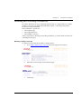
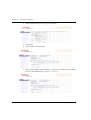
Running the Embedded Manager ........................................................ 215
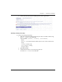
Installing the Java Plug-in.................................................................... 217
Installing the On-Line Help and Java Plug-In on your Web Site......... 218
Documentation .................................................................................... 218
Software Download.............................................................................. 218
Appendix B
Specifications................................................................................................... 219
P334T-ML Switch................................................................................. 219
Physical ...................................................................................... 219
Power Requirements ................................................................. 219
Environmental ........................................................................... 219
Safety – AC ................................................................................ 220
EMC Emissions .......................................................................... 220
Emissions ......................................................................... 220
Immunity ......................................................................... 220
Interfaces .................................................................................... 220
Standards Compliance ............................................................... 220
IEEE ................................................................................. 220
IETF ................................................................................. 221
Routing ............................................................................ 221
Basic MTBF ................................................................................ 221
Stacking Sub-module ........................................................................... 221
Basic MTBF ................................................................................ 221
Approved SFF/SFP GBIC Transceivers................................................. 222
Safety Information ..................................................................... 222
Laser Classification ........................................................... 222
Usage Restriction ............................................................. 222
Installation ................................................................................. 223
Installing and Removing a SFF/SFP GBIC Transceiver .... 223
Specifications ............................................................................. 223
LX Transceiver ................................................................. 223
P332GT-ML User’s Guide
xi
Contents
SX Transceiver .................................................................223
Agency Approval ........................................................................224
Gigabit Fiber Optic Cabling .................................................................. 224
Connector Pin Assignments ................................................................. 225
Console Pin Assignments ...........................................................225
CLI – Layer 2 Command Index ............................................................ 227
CLI – Layer 3 Command Index ............................................................ 231
How to Contact Us ............................................................................... 233
In the United States ....................................................................233
In the EMEA (Europe, Middle East and Africa) Region ............233
In the AP (Asia Pacific) Region ..................................................235
In the CALA (Caribbean and Latin America) Region ................235
xii
P332GT-ML User’s Guide
List of Figures
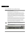
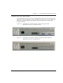
Figure 2.1 P334T-ML Front Panel ....................................................... 19
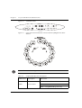
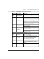
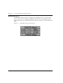
Figure 2.2 P334T-ML LEDs .................................................................. 20
Figure 2.3 Order of Function Parameters Selected with the Left/Right
Front Panel Buttons20
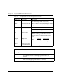
Figure 2.4 P334T-ML AC version Back Panel (with Stacking
Sub-module, BUPS-ML connector cover plate removed) .. 23
Figure 2.5 P334T-ML DC Back Panel (without Stacking Sub-module
installed, BUPS-ML connector cover plate shown) ............ 23
Figure 2.6 BUPS-ML Input Connector Sticker..................................... 24
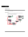
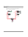
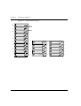
Figure 3.1 P330 stacks with a P882 backbone ..................................... 25
Figure 3.2 P330 stacks with a P330 backbone ..................................... 26
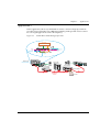
Figure 3.3 P334T-ML as Smart Workgroup Switch ............................. 27
Figure 4.1 P334T-ML Rack Mounting ................................................ 31
Figure 4.2 Incorrect Stack Connection ................................................ 33
Figure 4.3 P330 Stack Connections ..................................................... 34
Figure A.1 The Welcome Page............................................................ 215
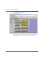
Figure A.2 Web-based Manager ......................................................... 216
P332GT-ML User’s Guide
xiii
List of Figures
xiv
P332GT-ML User’s Guide
List of Tables
Table 2.1
Table 2.2
Table 4.1
Table 4.2
Table 4.3
Table 5.1
Table 7.1
Table 7.2
Table 7.3
Table 7.4
Table 7.5
Table 7.6
Table 7.7
Table 7.8
Table 7.9
Table B.1
Table B.2
Table B.3
P332GT-ML User’s Guide
Avaya P334T-ML LED Descriptions.................................... 20
Avaya P334T-ML <- -> Select buttons .............................. 22
Default Switch Settings....................................................... 36
Default Port Settings ........................................................... 37
Gigabit Ethernet Cabling .................................................... 38
Navigation, Cursor Movement and Shortcuts .................... 52
System Commands ........................................................... 151
IP Commands.................................................................... 158
RIP Commands ................................................................. 177
OSPF Commands .............................................................. 183
VRRP Commands.............................................................. 190
SRRP Commands .............................................................. 197
BOOTP-DHCP Commands................................................ 200
Policy Commands ............................................................. 202
VLAN Commands ............................................................. 211
Stacking Sub-module........................................................ 221
Gigabit Fiber Optic Cabling............................................... 224
Pinout of the Required Connection for Console
Communications............................................................... 225
xv
List of Tables
xvi
P332GT-ML User’s Guide
Chapter 1
Overview
The P334T-ML is a powerful Multilayer Policy 10/100 BASE-T and Gigabit Ethernet
stackable switch. It enhances the P330 line to support high density multilayer 10/
100 BASE-T and Gigabit Ethernet solutions.
About the P334T-ML
Basic information about the P334T-ML follows:
• The Avaya P334T-ML has forty-eight 10/100Base-T and two GBIC (SFP) ports,
and provides Layer 2 and optional Layer 3 Ethernet switching. Like other
members of the Avaya P330 family, the P334T-MLis available in AC and DC
versions.
• Multilayer switching with QoS, Policy Management and multiple levels of
security and redundancy make the Avaya P334T-MLan ideal part of a
converged network. The P334T-MLis ready for voice and data applications, and
supports IEEE standards for VLAN Tagging, Gigabit Ethernet, Spanning Tree
and Flow Control.
• The Avaya P334T-MLcan be deployed with other products in the P330 family in
stacks of up to ten switches. This makes increasing port density or adding new
technologies as simple as “plug and play.”
Avaya P334T-ML Features
•
•
•
•
•
•
•
•
Up to 480 10/100Base-T ports in a stack.
Octaplane™ 8 Gbps stacking fabric
Stack, Port & LAG Redundancy
Multiple VLANs per port
RADIUS protocol for security
IP Multicast filtering
Terminal and modem interface
AC and DC versions
•
•
•
•
RIP v.1, RIP v.2, OSPF. ARP, ICMP,DHCP/BOOTP relay
VRRP and SRRP Redundancy
Quality of Service
Access control
Layer 3
P334T-ML User’s Guide
1
Chapter 1
Overview
Management & Monitoring
• Avaya™ MultiService Network Manager (MSNM™)
• Web-based manager
• CLI (Command Line Interface)
• RMON/SMON
2
P334T-ML User’s Guide
Chapter 1
Overview
Layer 2 Features
VLANs
The P334T-ML module is fully IEEE 802.1Q compliant and can handle up to 252
tagged VLANs from a range of 1 to 3071.
• Automatic VLAN Learning — This module learns the VLANs automatically
from traffic received on ports in “bind to all” mode. The maximum number of
VLANs, 252, includes these dynamically learned VLANs and any VLANs you
added manually.
Note: A P334T-ML, being a stack master, imposes a maximum number of 252
VLANs on the entire stack.
Multiple VLANs per Port
The P334T-ML provides the ability to set multiple VLANs per port. The three
available Port Multi-VLAN binding modes are:
• Bind to All - the port is programmed to support the entire 3K VLANs range.
Traffic from any VLAN is forwarded through a port defined as Bound to All.
• Bind to Configured - the port supports all the VLANs configured in the
switch/stack. These may be either Port VLAN IDs (PVID) or VLANs that were
manually added to the switch.
• Statically Bound - the port supports VLANs manually configured on it.
Note: VLAN Binding — The forwarding mechanism of the P330-ML switches is
based on frame’s VLAN and MAC address. If a frame is destined to a known MAC
address but arrives on a different VLAN than the VLAN on which this MAC
address was learnt, this frame will be flooded as unknown to all ports that are
bound to its VLAN. Hence, VLAN binding should be executed with care, especially
on ports connected to workstations or servers.
Spanning Tree
P334T-ML supports the IEEE 802.1D Standard Spanning Tree Protocol. This
protocol detects and eliminates logical loops in the network and automatically
places some ports on standby to form a network with the most efficient pathways.
P334T-ML User’s Guide
3
Chapter 1
Overview
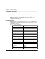
Link Aggregation Group (LAG)
LAG provides increased bandwidth and redundancy for critical high-bandwidth
applications such as inter-stack links and connections to servers. With the P334TML, you can aggregate the two GBIC ports to form a LAG, you can aggregate the
bandwidths of 6 groups of up to 8 10/100BaseT ports in a LAG, for a maximum of 7
LAGs per switch.
When created, each LAG is automatically assigned a logical Port Number. This
logical Port Number can then be used as any regular panel port for all configuration
required for the LAG (Spanning Tree, Redundancy, etc.).
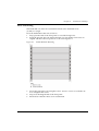
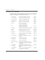
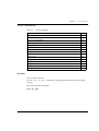
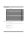
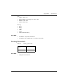
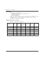
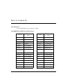
The relationship between the P334T-ML Port Numbers and the LAG logical Port
Number that will be assigned to each LAG is depicted below.
Panel Ports in the LAG
Max. Number of LAGs
LAG Logical Port Number
1-4, 25-28
1
101
5-8, 29-32
1
102
9-12, 33-36
1
103
13-16, 37-40
1
104
17-20, 41-44
1
105
21-24, 45-48
1
106
51,52
1
107
Link/Port Redundancy
Redundancy can be implemented between any two ports in the same stack at the
link level. You can also assign redundancy between any two LAGs in the stack or
between a LAG and a port. One port or LAG is defined as the primary port, and the
other as the secondary port. In case the primary port link fails, the secondary port
takes over.
Intermodule Redundancy
Intermodule redundancy includes all Port Redundancy functionality, and
additionally maintains port integrity even when the primary port link fails as the
result of a failure of the module. If the module on which the active port in an
Intermodule Redundancy pair is located is powered down or removed from the
stack, the secondary port in the Intermodule Redundancy pair takes over. Only one
pair per stack can be set for Intermodule Redundancy.
4
P334T-ML User’s Guide
Chapter 1
Overview
Stack Redundancy
In the unlikely event that a P330 switch or Octaplane link should fail, stack integrity
is maintained if the redundant cable is connected to the stack. The broken link is
bypassed and data transmission continues uninterrupted. The single management
IP address for the stack is also preserved for uninterrupted management and
monitoring. You can remove or replace any unit within the stack without disrupting
operation or performing stack-level reconfiguration.
Network Management Agent (NMA) Redundancy
Since each P334T-ML module has an integral SNMP agent, any module in a stack
can serve as the stack NMA while other NMAs act as redundant agents in “hot”
standby. If the “live” NMA fails then a backup is activated instantaneously.
Allowed Managers
With the Allowed Managers feature, the network manager can determine who may
or may not gain management access to the switch. The feature can be enabled or
disabled (default is disabled). When enabled, only those users that are configured in
the Allowed Managers table are able to gain Telnet, http, and SNMP management
access to the switch.
Radius Security
The Remote Authentication Dial-In User Service (RADIUS) is an IETF standard
(RFC 2138) client/server security protocol. Security and login information is stored
in a central location known as the RADIUS server. RADIUS clients such as the
P334T-ML, communicate with the RADIUS server to authenticate users.
All transactions between the RADIUS client and server are authenticated through
the use of a “shared secret” which is not sent over the network. The shared secret is
an authentication password configured on both the RADIUS client and its RADIUS
servers. The shared secret is stored as clear text in the client’s file on the RADIUS
server, and in the non-volatile memory of the P334T-ML. In addition, user
passwords are sent between the client and server are encrypted for increased
security.
Software Download
P334T-ML includes a safe software download procedure in which backup code is
always present.
You should perform a reset after downloading software to the Module.
Port Classification
With the P334T-ML, you can classify any port as regular or valuable. Setting a port
P334T-ML User’s Guide
5
Chapter 1
Overview
to valuable means that a link fault trap can be sent even when the port is disabled.
This feature is particularly useful for the link/intermodule redundancy application,
where you need to be informed about a link failure on the dormant port.
Network Time Acquiring Protocols
The P334T-ML supports the SNTP Protocol (RFC 958) over UDP port 123. You can
choose between SNTP or TIME protocol over UDP port 37.
IP Multicast Filtering
IP Multicast allows you to send a single copy of an IP packet to multiple
destinations, and can be used for various applications including video streaming
and video conferencing.
On LANs, IP Multicast packets are transmitted in MAC Multicast frames.
Traditional LAN switches flood these Multicast packets to all stations in the VLAN.
Multicast filtering functions may be added to the Layer 2 switches to avoid sending
Multicast packets where they are not required. Layer 2 switches capable of
Multicast filtering send the Multicast packets only to ports that connect members of
that Multicast group. In order for this feature to operate correctly, you need in your
network a router issuing IGMP queries.
Note: IP Multicast filtering will function only based on the port's VLAN ID and not
based on any VLAN bound to the port.
Congestion Control
Congestion control is a key element of maintaining network efficiency as it prevents
resource overload.
The P334T-ML supports congestion control on all Ethernet ports, using IEEE 802.3x
Flow Control in full duplex mode.
Backup Power Supply
Each P334T-ML module comes with a Backup Power Supply (BUPS) connector. If
the internal power supply fails, the BUPS-ML (available separately) automatically
supplies power to the switch for uninterrupted operation.
Note: The BUPS-ML used with P334T-ML units is different from the BUPS used with
other P330 products
6
P334T-ML User’s Guide
Chapter 1
Overview
Fans
The P334T-ML module fans have integrated sensors which provide advance
warnings of fan failure via management.
P334T-ML User’s Guide
7
Chapter 1
Overview
Layer 3 Features
Modes of Operation
The P334T-ML has two modes of operation (in each mode, Layer 2 is always active):
• Layer 2-only mode
• Router mode and Layer 2.
Note: This section is only applicable if you either purchased a preconfigured
P334T-ML or purchased a Routing License Key Certificate and activated the License
Key
Forwarding
The P334T-ML forwards IP packets between IP networks. When it receives an IP
packet through one of its interfaces, it forwards the packet through one of its
interfaces. P334T-ML supports multinetting, enabling it to forward packets between
IP subnets on the same VLAN as well as between different VLANs. Forwarding is
performed through standard means in Router mode.
Redundancy
Routing protocols naturally provide some level of redundancy. However, IP
stations that are manually configured with a single ‘default gateway’ IP address do
not naturally recover when their default gateway fails. These stations do not
automatically try to use other routers or Layer-3-switches connected to the same
subnet.
The P334T-ML supports two router redundancy protocols, VRRP and SRRP, to
solve this problem.
Virtual Router Redundancy Protocol (VRRP)
VRRP is an IETF protocol designed to support redundancy of routers on the LAN,
as well as load balancing of traffic. VRRP is transparent to host stations, making it
an ideal choice when redundancy, load balancing and ease of configuration are all
required.
The concept underlying VRRP is that a router can backup other routers, in addition
to performing its primary routing functions. This redundancy is achieved by
introducing the concept of a virtual router. A virtual router is a routing entity
associated with multiple physical routers. The routing functions of the virtual router
are performed by one of the physical routers with which it is associated. This router
is known as the master router.
For each virtual router, VRRP selects a master router. If the selected master router
fails, another router is selected as master router.
8
P334T-ML User’s Guide
Chapter 1
Overview
In VRRP, two or more physical routers can be associated with a virtual router, thus
achieving the extreme reliability inherent in the SAFER architecture.
In a VRRP environment, host stations interact with the virtual router. They are not
aware that this router is a virtual router, and they are not affected when a new
router takes over the role of master router. This makes VRRP fully interoperable
with every host station.
VRRP can be activated on an interface using a single command while allowing for
the necessary fine-tuning of the many VRRP parameters. For a detailed description
of VRRP, refer to VRRP standards and published literature.
Simple Router Redundancy Protocol (SRRP)
P334T-ML IP SRRP redundancy capabilities provide automatic backup Layer 3
switching for IP stations. P334T-ML units can be configured to back each other up
so that if one fails the other will take over its forwarding functions. The backup
P334T-ML is not idle. As long as both P334T-ML units are functional, traffic is
shared between them. The P334T-ML modules can be in the same P330 stack or in
different, connected, P330 stacks. The P334T-ML can back up another P334T-ML
unit or any other router.
A P334T-ML unit configured to back up another unit monitors the other’s status by
polling it at configured intervals, and automatically detects when the other fails and
when it becomes functional again. When detecting a failure, the backup P334T-ML
sends a gratuitous ARP message that causes all stations to send their IP traffic to the
backup P334T-ML MAC address instead of the failed unit MAC address. As long as
it is an active backup resulting from the failure of the main unit, the backup P334TML answers ARP requests for the main unit, providing its own MAC address.
Policy — Quality of Service (QoS)
The P334T-ML supports QoS by using multiple priority levels and IEEE 802.1p
priority tagging to ensure that data and voice receive the necessary levels of service.
The P334T-ML can enforce policy on routed packets (per packet), according to four
criteria:
• The Diff-Serv byte (TOS field) in the IP header of the incoming packet.
• Matching the packet’s source or destination IP address to the configured
priority policy.
• Whether the packet source or destination TCP/UDP port number falls within a
pre-defined range.
The P334T-ML can enforce centralized network policies using the Avaya
MultiService Network Manager central policy management application.
P334T-ML User’s Guide
9
Chapter 1
Overview
Policy — Access Control
The P334T-ML supports Access Control policy. The P334T-ML uses policy lists
containing both Access Control rules and QoS rules. The policy lists are ordered by
rule indexing. Access Control rules define how the P334T-ML should handle routed
packets. There are three possible ways to handle such packets:
• Forward the packet (Permit operation)
• Discard the packet (Deny operation)
• Discard the packet and notify the management station (Deny and Notify)
The P334T-ML can enforce Access Control policy on each routed packet, according
to the following criteria:
• Matching the packet's source or destination IP address to the configured Access
Control policy.
• Determine if the packet source or destination TCP/UDP port number falls
within a pre-defined range.
• Using the ACK bit of the TCP header.
The P334T-ML access control rules are set-up using the Command Line Interface
and the Avaya MultiService Network Manager central policy management
application.
DHCP/BOOTP Relay
The P334T-ML supports the DHCP/BOOTP Relay Agent function. This is an
application that accepts DHCP/BOOTP requests that are broadcast on one VLAN
and sends them to a DHCP/BOOTP server that connects to another VLAN or a
server that may be located across one or more routers that would otherwise not get
the broadcast request. The relay agent handles the DHCP/BOOTP replies as well,
transmitting them to the client directly or as broadcast, according to a flag in the
reply message. Note that the same DHCP/BOOTP relay agent serves both the
BOOTP and DHCP protocols.
When there is more than one IP interface on a VLAN, the P334T-ML chooses one of
the IP addresses on this VLAN when relaying the DHCP/BOOTP request. The
DHCP/BOOTP server then uses this address to decide from which subnet the
address should be allocated.
When the DHCP/BOOTP server is configured to allocate addresses only from a
single subnet among the different subnets defined on the VLAN, you may need to
configure the P334T-ML with the relay address on that subnet so that the DHCP/
BOOTP server can accept the request.
DHCP/BOOTP Relay in P334T-ML is configurable per VLAN and allows for two
DHCP/BOOTP servers to be specified. In this case, it duplicates each request, and
sends it to both servers. This provides redundancy and prevents the failure of a
single server from blocking hosts from loading.
DHCP/BOOTP Relay in P334T-ML can be enabled or disabled.
10
P334T-ML User’s Guide
Chapter 1
Overview
RIP
P334T-ML supports the widely used RIP routing protocol (both RIPv1 and RIPv2).
The RIPv1 protocol imposes some limitations on the network design with regard to
subnetting. When operating RIPv1, you must not configure variable length subnet
masks (VLMS). Each IP network must have a single mask, implying that all subnets
in a given IP network are of the same size. Also, when operating RIPv1, you must
not configure supernets, which are networks with a mask smaller than the natural
net mask of the address class, such as 192.1.0.0 with mask 255.255.0.0 (smaller than
the natural class C mask which is 255.255.255.0). For detailed descriptions of RIP
refer to the standards and published literature.
RIPv2 is a new version of the RIP routing protocol, not yet widely used but with
some advantages over RIPv1. RIPv2 solves some of the problems associated with
RIPv1. The most important change in RIPv2 is the addition of a subnet mask field
which allows RIPv2 to support variable length subnets. RIPv2 also includes an
authentication mechanism similar to the one used in OSPF.
Configuration of the RIP version, 1 or 2, is per IP interface (default is version 1).
Configuration should be homogenous on all routers on each subnet, i.e. there
should not be both RIPv1 and RIPv2 routers on the same subnet. However, different
IP interfaces of the P334T-ML can be configured with different RIP versions (as long
as all routers on the subnet are configured to the same version).
RIPv2 and RIPv1 are considered the same protocol with regard to redistribution to/
from OSPF and static route preferences.
OSPF
P334T-ML supports the OSPF routing protocol. P334T-ML can be configured as an
OSPF Autonomous System Boundary Router (ASBR) by configuration of route
redistribution. P334T-ML can be installed in the OSPF backbone area (area 0.0.0.0)
or in any OSPF area that is part of a multiple areas network. However, P334T-ML
cannot be configured to be an OSPF area border router itself.
The P334T-ML supports the equal-cost multipath (ECMP) feature which allows load
balancing by splitting traffic between several equivalent paths.
While OSPF can be activated with default values for each interface using a single
command, many of the OSPF parameters are configurable.
For a detailed description of OSPF, refer to the OSPF standards and published
literature.
Static Routes
Static routes can be configured to the P334T-ML. They are never timed-out, or lost
over reboot, and can only be removed by manual configuration. Deletion (by
configuration) of the IP interface deletes the static routes using this interface as well.
A static route becomes inactive if the interface over which it is defined is disabled.
P334T-ML User’s Guide
11
Chapter 1
Overview
When the interface is enabled, the static route becomes active again.
Static routes can only be configured for remote destinations, i.e. destinations that
are reachable via another router as a next hop. The next hop router must belong to
one of the directly attached networks for which P334T-ML has an IP interface.
“Local” static routes, such as those that have no next hop, are not allowed.
Two kinds of static routes can be configured, High Preference static routes which
are preferred to routes learned from any routing protocol and Low Preference static
routes which are used temporarily until the route is learned from a routing protocol.
By default, a static route has Low Preference.
Static routes can be advertised by routing protocols (i.e. RIP, OSPF) as described
under Route redistribution.
Static routes also support load-balancing similar to OSPF. A static route can be
configured with multiple next hops so that traffic is split between these next hops.
This can be used for example to load-balance traffic between several firewalls which
serve as the default gateway.
Route Redistribution
Route redistribution is the interaction of multiple routing protocols. OSPF and RIP
can be operated concurrently in P334T-ML. In this case, P334T-ML can be
configured to redistribute routes learned from one protocol into the domain of the
other routing protocol. Similarly, gor routes may be redistributed to RIP and to
OSPF. Route redistribution should not be configured carelessly, as it involves metric
changes and might cause routing loops in the presence of other routes with
incompatible schemes for route redistribution and route preferences.
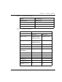
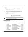
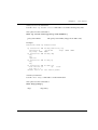
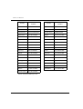
The P334T-ML scheme for metric translation in route redistribution is as follows:
• Static to RIP metric configurable (default 1)
• OSPF internal metric N to RIP metric 1
• OSPF external type 1 metric N to RIP metric 1
• OSPF external type 2 metric N to RIP metric N+1
• Static to OSPF external type 2, metric configurable (default 1)
• RIP metric N to OSPF external type 2, metric N
• Direct to OSPF external type 2, metric 1.
By default, the P334T-ML does not redistribute routes between OSPF and RIP.
Redistribution from one protocol to the other can be configured. Static routes are, by
default, redistributed to RIP and OSPF. P334T-ML allows the user to globally
disable redistribution of static routes to RIP, and separately to globally disable
redistribution of static routes to OSPF. In addition, P334T-ML lets the user
configure, on a per static route basis, whether the route is to be redistributed to RIP
and OSPF, and what metric (in the range of 1-15). The default state is to enable the
route to be redistributed at metric 1. When static routes are redistributed to OSPF,
they are always redistributed as external type 2.
12
P334T-ML User’s Guide
Chapter 1
Overview
Route Preferences
The routing table may contain routes from different sources. Routes to a certain
destination may be learned independently from RIP and from OSPF, and at the
same time, a static route can also be configured to the same destination. While
metrics are used to choose between routes of the same protocol, protocol
preferences are used to choose between routes of different protocols.
The preferences only apply to routes for the same destination IP address and mask.
They do not override the longest-match choice. For example, a high-preference
static default route will not be preferred over a RIP route to the subnet of the
destination.
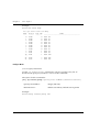
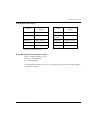
P334T-ML protocol preferences are listed below from the most to the least preferred:
1 Local (directly attached net)
2 High-preference static (manually configured routes)
3 OSPF internal routes
4 RIP
5 OSPF external routes
6 Low-preference static (manually configured routes).
NetBios Rebroadcast
The P334T-ML can be configured to relay NetBios UDP broadcast packets. This
feature is used for applications such as WINS that use broadcast but may need to
communicate with stations on other subnets or VLANs.
Configuration is performed on a per-interface basis. When a NetBios broadcast
packet arrives from an interface on which NetBios rebroadcast is enabled, the
packet is distributed to all other interfaces configured to rebroadcast NetBios.
If the NetBios packet is a net-directed broadcast (e.g., 149.49.255.255), the packet is
relayed to all other interfaces on the list, and the IP destination of the packet is
replaced by the appropriate interface broadcast address.
If the NetBios broadcast packet is a limited broadcast (e.g., 255.255.255.255), it is
relayed to all VLANs on which there are netbios-enabled interfaces. In that case, the
destination IP address remains the limited broadcast address.
Multinetting (Multiple Subnets per VLAN)
In Router Mode, most applications such as RIP and OSPF, operate per IP interface.
Other applications such as VRRP and DHCP/BOOTP Relay operate per VLAN.
Configuration of these applications is done in the Interface mode. When there is
only a single interface (subnet) per VLAN then system behavior is intuitive since a
subnet and a VLAN are the same.
If the configuration includes multiple interfaces (subnets) per VLAN things start to
get complicated.
P334T-ML User’s Guide
13
Chapter 1
Overview
For example, if there are two interfaces over the same VLAN and you configure
DHCP server on one interface it will be used also for the second interface over the
same VLAN. This behavior might be less expected and in some cases wrong.
In order to prevent misconfiguration and unexpected results, the P334T-ML
prevents configuration of VLAN-oriented commands on an interface unless the user
explicitly requested to using the new "enable vlan commands" CLI command.
Configuration of "enable vlan commands" on an interface overrides this
configuration on other interfaces that belong on the same VLAN.
This ensures that VLAN-oriented commands can be configured from one interface
only.
In case there is only one interface over a VLAN, then VLAN oriented commands for
this VLAN can be configured through the single interface without the need to issue
the "enable vlan command" command.
Note:
1. VLAN-oriented commands that were configured affect the VLAN of the interface
that was used at the time the command was issued.
2. If the interface is moved to another VLAN (using the "ip vlan command") VLAN
oriented configuration still relates to the original VLAN.
Router Configuration File
The Configuration File feature allows the user to read the P334T-ML routing
configuration parameters and save them to a file on the station. The routing
configuration commands in the file are in CLI format. The user can edit the file (if
required) and re-configure the P334T-ML by downloading the configuration file.
Although the file can be edited, it is recommended to keep changes to the file to a
minimum. The recommended configuration method is using MSNM P330 Device
Manager and/or the CLI. Changes to the configuration file should be limited to
those required to customize a configuration file from one router to suit another.
14
P334T-ML User’s Guide
Chapter 1
Overview
Avaya P334T-ML Standards Supported
The P334T-ML complies with the following standards.
IEEE
•
•
•
•
•
802.3x Flow Control on all ports
802.1q/p VLAN Tagging support on all ports
802.1D Spanning Tree protocol
802.3z Gigabit Ethernet on ports 51,52
IEEE 802.3u Ethernet/Fast Ethernet on ports 1-48
•
•
•
•
MIB-II - RFC 1213
Structure and identification of management information for TCP/IP-based
Internet - RFC 1155
Simple Network Management Protocol (SNMP) - RFC 1157
PPP Internet Protocol Control Protocol (IPCP) - RFC 1332
PPP Authentication Protocols (PAP & CHAP) - RFC 1334
PPP - RFC 1661
ATM Management - RFC 1695
RMON - RFC 1757
SMON - RFC 2613
Bridge MIB Groups - RFC 2674 dot1dbase and dot1dStp fully implemented.
Support for relevant MIB objects: dot1q (dot1qBase, dot1qVlanCurrent)
The Interfaces Group MIB - RFC 2863
Remote Authentication Dial In User Service (RADIUS) - RFC 2865
•
•
•
•
•
•
•
•
•
•
•
•
•
Internet Protocol - RFC 791
Internet Control Message Protocol - RFC 792
Ethernet Address Resolution Protocol - RFC 826
Standard for the transmission of IP datagrams over Ethernet - RFC 894
Broadcasting Internet datagrams in the presence of subnets - RFC 922
Internet Standard Subnetting Procedure - RFC 950
Bootstrap Protocol - RCF 951
Using ARP to implement transparent subnet gateways - RFC 1027
Routing Information Protocol - RCF 1058
Hosts Extensions for IP Multicasting - RFC 1112
Requirements for Internet Hosts - Communications Layers - RFC 1122
DHCP Options and BOOTP Vendor Extensions - RFC 1533
Interoperation between DHCP and BOOTP - RFC 1534
IETF - Layer 2
•
•
•
•
•
•
•
•
IETF - Layer 3
P334T-ML User’s Guide
15
Chapter 1
Overview
•
•
•
•
•
•
•
•
•
Dynamic Host Configuration Protocol - RFC 1541
Clarifications and Extensions for the Bootstrap Protocol Information - RFC 1542
OSPF Version 2 - RFC 1583
RIP Version 2 Carrying Additional Information - RFC 1723
RIP Version 2 MIB Extension - RFC 1724
Requirements for IP Version 4 Routers - RFC 1812
OSPF Version 2 Management Information Base - RFC 1850
IP Forwarding Table MIB - RFC 2096
Virtual Router Redundancy Protocol - RFC 2338
Avaya P334T-ML Network Management
Comprehensive network management is a key component of today’s networks.
Therefore we have provided multiple ways of managing the P334T-ML to suit your
needs.
P334T-ML Device Manager (Embedded Web)
The built-in P330 Device Manager (Embedded Web Manager) allows you to manage
a P330 stack using a Web browser without purchasing additional software. This
application works with the Microsoft® Internet Explorer and Netscape® Navigator
web browsers and Sun Microsystems Java™ Plug-in.
P334T-ML Command Line Interface (CLI)
The P334T-ML CLI provides a terminal type configuration tool for configuration of
P334T-ML features and functions. You can access the CLI locally, through the serial
interface, or remotely via Telnet.
MSNM™
When you need extra control and monitoring or wish to manage other Cajun
Campus equipment, then the MSNM network management suite is the answer. This
suite provides the ease-of-use and features necessary for optimal network
utilization.
• MSNM is available for Windows® 95/NT®/2000 and Solaris 2.8
• MSNM can operate in Stand-Alone mode with Windows® NT®/2000 and
Solaris 2.8.
• MSNM operates under HP OpenView for Windows® 95/NT®/2000.
16
P334T-ML User’s Guide
Chapter 1
Overview
Avaya P334T-ML Network Monitoring
RMON I MIBs - RFC 1757
• RMON I support for the following standard monitoring MIBs:
— Statistics
— History
— Alarms
— Events
SMON MIBs - RFC 2613
• SMON support for the following standard monitoring MIBs:
— Data Source Capabilities
— Port Copy
— VLAN and Priority Statistics.
Bridge MIB Groups - RFC 2674
• dot1dbase and dot1dStp fully implemented.
• Support for relevant MIB objects: dot1q (dot1qBase, dot1qVlanCurrent).
Port Mirroring
The P334T-ML provides port mirroring for additional network monitoring
functionality. You can filter the traffic and mirror either incoming traffic to the
source port or both incoming and outgoing traffic. This allows you to monitor the
network traffic you need.
Ports which are members in a Link Aggregation Group (LAG) cannot also be used as
Port Mirroring Destination or Source ports.
Within the P334T-ML switch, port mirroring can be configured between ports in the
three following groups:
• 1-12, 25-36
• 13-24, 37-48
• 51, 52
On the stack level, port mirroring pairs can be configured between any Giga port,
and between any Giga port on the P334T-ML and any 10/100Mbps port not residing
on a P334T-ML.
SMON
The P334T-ML supports Avaya’s ground-breaking SMON Switched Network
Monitoring, which the IETF has now adopted as a standard (RFC2613). SMON
provides unprecedented top-down monitoring of switched network traffic at the
P334T-ML User’s Guide
17
Chapter 1
Overview
following levels:
• Enterprise Monitoring
• Device Monitoring
• VLAN Monitoring
• Port-level Monitoring
This top-down approach gives you rapid troubleshooting and performance
trending to keep the network running optimally.
Note: MSNM Licence is required to run SMON monitoring.
Note: You need to purchase one SMON License per P330 Stack
18
P334T-ML User’s Guide
Chapter 2
Avaya P334T-ML Front and Rear Panels
Avaya P334T-ML Front Panel
The P334T-ML front panel contains LEDs, controls, and connectors. The status LEDs
and control buttons provide at-a-glance information.
The front panel LEDs consist of Port LEDs and Function LEDs. The Port LEDs
display information for each port according to the illuminated function LED. The
function is selected by pressing the left or right button until the desired parameter
LED is illuminated. Each Function is displayed first for ports 1-24. Pressing the
same button a second time displays the function for ports 25-48 (see Figure 2.3).
Pressing the same button a third time will move to the next function. When the 2548 LED is OFF, ports 1-24 are displayed, and when the 25-48 LED is ON, ports 25-48
are displayed. The information for the SFP ports (51, 52) is displayed regardless of
the status of the 25-48 LED.
For example, if the COL LED is illuminated, and the 25-48 LED is off, then all Port
LEDs show the collision status of ports 1-24. If you wish to select the LAG function
for the same ports, then press the right button until the LAG Function LED is lit and
the 25-48 LED is OFF. If you then wish to select Rx for ports 25-48, press the left
button several times until both the Rx function LED and the 25-48 LED light.
The P334T-ML front panel shown below includes LEDs, buttons, SFP GBIC
transceiver housings 10/100 Base-T ports and the RJ-45 console connector (refer to
Figure 2.1 and Figure 2.2). The LEDs are described in Table 2.1.
Note: The 10/100BaseT ports of the P334T-ML are numbered from 1-48. The two
SFP Gigabit Ethernet ports are numbered 51,52. Port LED numbers 49-50 are
reserved.
Figure 2.1
P334T-ML User’s Guide
P334T-ML Front Panel
19
Chapter 2
Avaya P334T-ML Front and Rear Panels
Figure 2.2
P334T-ML LEDs
51
52
53
54
55
56
LNK COL
Figure 2.3
1
2
3
4
5
6
7
8
9
10
11
12
13
14
15
16
17
18
19
20
21
22
23
24
Tx
Rx
FDX
FC Hspd LAG
25-48
Rout SYS OPR PWR
Order of Function Parameters Selected with the Left/Right Front Panel
Buttons
Note: All LEDs are lit during a reset.
Table 2.1
LED Name
Avaya P334T-ML LED Descriptions
Description
LED Status
OFF – Power is off
PWR
Power Status
ON – Power is on
Blink – Using BUPS-ML power only
20
P334T-ML User’s Guide
Chapter 2
Table 2.1
Avaya P334T-ML Front and Rear Panels
Avaya P334T-ML LED Descriptions (Continued)
LED Name
Description
OPR
CPU Operation
LED Status
OFF – Module is booting
ON – Normal operation
OFF – Module is a slave in a stack
SYS
System Status
ON – Module is the master of the stack and
the Octaplane and Redundant (optional)
cable(s) are connected correctly.
This LED will also light in Standalone mode.
Blink – Box is the master of the stack and the
Octaplane is in redundant mode.
ROUT
25-48
Routing Mode
Port Display
Mode
OFF – Layer 2 mode
ON – Router mode
OFF – Ports 1-24, 51-52 are displayed in the
Port LEDs, if selected
ON – Ports 25-48, 51-52 are displayed in the
Port LEDs, if selected
The following Function LEDs apply to all ports
LNK
Port Status
ON – Link is OK
OFF – Port is disabled
Blink – Port is enabled, but Link is down
COL
Collision
OFF – No collision or full-duplex port for
ports 1 -48; always OFF for ports 51-52.
ON – Collision occurred on line.
OFF – No transmit activity
Tx
Transmit to line
ON – Data transmitted on line from the
module
OFF – No receive activity
Rx
P334T-ML User’s Guide
Receive from line
ON – Data received from the line into the
module
21
Chapter 2
Avaya P334T-ML Front and Rear Panels
Table 2.1
Avaya P334T-ML LED Descriptions (Continued)
LED Name
Description
FDX
Full Duplex mode
LED Status
ON – Full duplex mode (ports 1-48)
OFF – Half duplex mode (ports 1-48)
Always ON for ports 51,52 (full-duplex mode
only)
OFF – No flow control.
ON – One of the three possible flow control
modes is enabled.
FC
Flow Control
Hspd
High Speed
Note: FC LED for Gigabit Ethernet ports
reflect the last negotiated mode when
autonegotiation is enabled and the link is
down.
OFF:
ON:
Link Aggregation
Group (Trunking)
LAG
Table 2.2
22
Ports 1-48
Ports 51,52
10 Mbps N/A
100 Mbps 1000 Mbps
OFF – No LAG defined for this port
ON – Port belongs to a LAG
Avaya P334T-ML <- -> Select buttons
Description
Function
Left/Right
Individual – select LED function (see table above)
Reset module
Press both right and left buttons together for approximately 2
seconds. All LEDs on module light up until buttons are
released.
Reset stack
Press both Right and Left buttons together for 4 seconds. All
LEDs on stack light up until buttons are released.
P334T-ML User’s Guide
Chapter 2
Avaya P334T-ML Front and Rear Panels
Avaya P334T-ML Back Panel
The P334T-ML back panel contains a Stacking Sub-module slot, power supply and
BUPS-ML connector. Figure 2.2 shows the back panel of the AC version switch and
Figure 2.3 shows the back panel of the DC version switch with a stacking submodule installed.
Figure 2.4
P334T-ML AC version Back Panel (with Stacking Sub-module,
BUPS-ML connector cover plate removed)
Figure 2.5
P334T-ML DC Back Panel (without Stacking Sub-module installed,
BUPS-ML connector cover plate shown)
P334T-ML User’s Guide
23
Chapter 2
Avaya P334T-ML Front and Rear Panels
BUPS-ML Input Connector
The BUPS-ML input connector (see Figure 2.2 and Figure 2.3) is a 3.3 VDC and 5
VDC connector for use with the P330 BUPS-ML unit only. A BUPS Input sticker
appears directly above the BUPS-ML input connector, which is covered with a metal
plate.
Figure 2.6
24
BUPS-ML Input Connector Sticker
P334T-ML User’s Guide
Chapter 3
Applications
The following section describes typical applications for the P334T-ML in a network
with other Avaya products.
Application 1
This application shows P882 as the network backbone with P332G-ML as a
distribution with LAG and redundant links.
Figure 3.1
P330 stacks with a P882 backbone
Avaya P334T-ML
10/100 Mbps Ethernet
10/100 Mbps
Ethernet
LAG
Redundancy
Gigabit
Ethernet
with LAG
Gigabit Ethernet
with LAG
4 x 100 Mbps
Ethernet
LAG
Avaya P332GT-ML
Gigabit Ethernet
with LAG
Avaya P332G-ML
Avaya P880
Server Farm
Avaya P882 4x100 Mbps
LAG
P334T-ML User’s Guide
25
Chapter 3
Applications
Application 2
This application shows a P332G-ML as the multilayer SMB backbone, the P332GTML as the server farm switch and P330 stack as closet devices
Figure 3.2
P330 stacks with a P330 backbone
Avaya P333T & P334T
Avaya P333T & P334T
10/100 Mbps Ethernet
10/100 Mbps
Ethernet
LAG
Redundancy
Gigabit Ethernet
with LAG
Avaya P333T
Gigabit
Ethernet
with LAG
Avaya P334T-ML
4 x 100 Mbps
Ethernet
LAG
Gigabit Ethernet
with LAG
2 x Avaya P332G-ML
Avaya P332GT-ML
Server Farm
26
P334T-ML User’s Guide
Chapter 3
Applications
Application 3
In this application, the Avaya P334T-ML is used as a smart workgroup switch. It
provides Policy enforced Layer 2 Ethernet switching with QoS and Access Control
for converged applications such as IP telephony.
Figure 3.3
P334T-ML as Smart Workgroup Switch
Policy Rules
Access Control
QoS
Voice
Data
Unauthorized
High CoS
Low CoS
Dropped
Avaya™ P333T
Avaya™ P882
Avaya™ P334T-ML
Avaya P880
Avaya™ IP
Phone
Avaya™ P332G-ML
Avaya P332G-ML
Avaya™ P332GT-ML
Gigabit Ethernet
with LAG
P334T-ML User’s Guide
Avaya P334T-ML
Avaya P332G-ML
Data Center
27
Chapter 3
28
Applications
P334T-ML User’s Guide
Chapter 4
Installation and Setup
The P334T-ML is ready to work after you complete the installation instructions
below. The P334T-ML ports provide complete connectivity and no configuration is
required to make the system work.
Installing the X330STK-ML Stacking Sub-Module
Caution: The stacking sub-modules contain components sensitive to electrostatic
discharge. Do not touch the circuit board unless instructed to do so.
To install the stacking sub-module in the P334T-ML:
1 Remove the blanking plate from the back of the P334T-ML switch.
2 Insert the stacking sub-module gently into the slot, ensuring that the metal base
plate is aligned with the guide rails. The metal plate of the X330STK-ML (and
not the PCB) fits onto the guide rails.
3 Press the sub-module in firmly until it is completely inserted into the
P334T-ML.
4 Gently turn the two screws on the side panel of the stacking sub-module until
they are secure.
Note: The P334T-ML must not be operated with the back-slot open. The stacking submodule should be covered with the supplied blanking plate if necessary.
Note: Only use the X330STK-ML stacking module with the P334T-ML.
P334T-ML User’s Guide
29
Chapter 4
Installation and Setup
Positioning
The P334T-ML can be mounted alone or in a stack in a standard 19-inch equipment
rack in a wiring closet or equipment room. Up to 10 units can be stacked in this way.
When deciding where to position the unit, ensure that:
• It is accessible and cables can be connected easily and according to the
configuration rule.
• Cabling is away from sources of electrical noise such as radio transmitters,
broadcast amplifiers, power lines and fluorescent lighting fixtures.
• Water or moisture cannot enter the unit case.
• Air-flow around the unit and through the vents in the back and sides of the case
is not restricted.
Note: Use Octaplane cables to interconnect with other switches.
30
P334T-ML User’s Guide
Chapter 4
Installation and Setup
Rack Mounting
The P334T-ML case fits in most standard 19-inch racks. P334T-ML is 2U
(88 mm, 3.5”) high.
Place the P334T-ML in the rack as follows:
1 Snap open the ends of the front panel to reveal the fixing holes.
2 Insert the unit into the rack. Ensure that the four P334T-ML screw holes are
aligned with the rack hole positions as shown in Figure 4.1.
Figure 4.1
3
4
5
P334T-ML Rack Mounting
Secure the unit in the rack using the screws. Use two screws on each side. Do
not overtighten the screws.
Snap close the hinged ends of the front panel.
Ensure that ventilation holes are not obstructed.
P334T-ML User’s Guide
31
Chapter 4
Installation and Setup
Connecting Stacked Switches
Note: The two ends of the Octaplane cable terminate with different connectors. Each
connector can only be connected to its matching port.
The following cables are used to connect stacked switches:
• Short Octaplane cable (X330SC) – ivory-colored, used to connect adjacent
switches (Catalog No. CB0223) or switches separated by a BUPS unit.
• Long/Extra Long Octaplane cable (X330LC/X330L-LC) – ivory-colored, used to
connect switches from two different physical stacks, or switches separated by a
BUPS unit (Catalog No. CB0225/CB0270).
• Redundant/Long Redundant Octaplane cable (X330RC/X330L-RC) – black,
used to connect the top and bottom switches of a stack (Catalog No. CB0222/
CB0269).
These are the same cables that are used with all the P330 switches.
To connect stacked switches:
Note: When adding a module to an existing stack, first connect the stacking cables
and then power up the module.
1
2
3
4
5
Plug the light grey connector of the Short Octaplane cable into the port marked
“to upper unit” of the bottom P330 Family module.
Plug dark grey connector of same Short Octaplane cable to the port marked “to
lower unit” in the unit above. The connections are illustrated in Figure 4.3.
Repeat Steps 1 and 2 until you reach the top switch in the stack.
If you wish to implement stack redundancy, use the Redundant Cable to
connect the port marked “ to lower unit” on the bottom switch to the port
marked “to upper unit” on top switch of the stack.
Power up the added modules.
Caution: Do not cross connect two P330 switches with two Octaplane (light-colored)
cables. If you wish to cross-connect for redundancy, use one light-colored Octaplane
cable and one black redundancy cable. Figure 4.2 shows an incorrect connection.
32
P334T-ML User’s Guide
Chapter 4
Installation and Setup
Note: You can build a stack of up to 10 P330 switches (any mixture of P330 and
P330-ML modules wihin a stack is possible). If you do not wish to stack all the
switches in a single rack, use long Octaplane cables to connect two physical stacks
as shown in Figure 4.3.
Figure 4.2
Incorrect Stack Connection
BUPS
Connector
Cable to
Lower Unit
Cable to
Upper Unit
Cable to
Lower Unit
Cable to
Upper Unit
Power Supply
Connector
BUPS
Connector
Power Supply
Connector
Note: Figures 4.2 and 4.3 show the back panel of a P330 switch AC version. These
drawings also apply to the P330-ML products.
P334T-ML User’s Guide
33
Chapter 4
Installation and Setup
Figure 4.3
P330 Stack Connections
BUPS
Connector
BUPS
Connector
Cable to
Lower Unit
Cable to
Upper Unit
5
Power Supply
Connector
X330SC
BUPS
Connector
Cable to
Lower Unit
Cable to
Upper Unit
Cable to
Upper Unit
10
Cable to
Lower Unit
Cable to
Upper Unit
9
Cable to
Lower Unit
Cable to
Upper Unit
Cable to
Lower Unit
Cable to
Upper Unit
Cable to
Lower Unit
Cable to
Upper Unit
BUPS
Connector
4
Power Supply
Connector
Power Supply
Connector
BUPS
Connector
BUPS
Connector
Cable to
Lower Unit
Cable to
Upper Unit
3
Power Supply
Connector
8
Power Supply
Connector
BUPS
Connector
BUPS
Connector
Cable to
Lower Unit
Cable to
Upper Unit
2
Power Supply
Connector
Power Supply
Connector
BUPS
Connector
BUPS
Connector
X330RC
Power Supply
Connector
Cable to
Lower Unit
Power Supply
Connector
Cable to
Lower Unit
Cable to
Upper Unit
1
7
6
Power Supply
Connector
X330LC
34
P334T-ML User’s Guide
Chapter 4
Installation and Setup
Powering On – P334T-ML Module AC
For the AC input version of the P334T-ML, insert the AC power cord into the power
inlet in the back of the unit. The unit powers up.
If you are using a BUPS, insert a power cord from the BUPS-ML into the BUPS
connector in the back of the unit. The unit powers up even if no direct AC power is
applied to it.
Caution: Ensure that you connect your P334T-ML units to the BUPS-ML only. The
P330 BUPS is not compatible with P334T-ML units.
After power up or reset, the P334T-ML performs a self test procedure.
Powering On – P334T-ML Module DC
For the DC input version of the P334T-ML:
1 Connect the power cable to the switch at the input terminal block. Note that:
— The terminals are marked “+”, “-“ and the IEC 5019a Ground symbol.
— The size of the three screws in the terminal block is M3.5.
— The pitch between each screw is 9.5mm.
Warning: Before performing any of the following procedures, ensure that DC power
is OFF.
Caution: This product is intended for installation in restricted access areas and is
approved for use with 18 AWG copper conductors only. The installation must
comply with all applicable codes.
2
Connect the power cable to the DC power supply.
Warning: The proper wiring sequence is ground to ground, positive to positive and
negative to negative. Always connect the ground wire first and disconnect it last.
After power up or reset, the P334T-ML performs a self test procedure.
P334T-ML User’s Guide
35
Chapter 4
Installation and Setup
Configuring the Switch
The P334T-ML may be configured using the text-based CLI, the P330 Embedded
Web Manager or Avaya MultiService Network Manager (MSNM).
For instructions on the text-based CLI, refer to Chapter 4, CLI – Layer 2.
For instructions on installation of the Graphical User Interfaces (GUI), refer to
Appendix A, P330 Embedded Web Manager. For instructions on the use of the
graphical user interfaces, refer to the Device Manager User’s Guide on the
Documentation and Utilities CD.
P334T-ML Default Settings
The default settings for the P334T-ML switch and its ports are determined by the
P334T-ML software. These default settings are subject to change in newer versions
of the P334T-ML software.
Table 4.1
36
Default Switch Settings
Function
Default Setting
IP Address
149.49.32.134
Subnet Mask
255.255.255.0
Default gateway
0.0.0.0
Management VLAN ID
1
Spanning tree
Enabled
Bridge priority for Spanning
Tree
32768
Keep alive frame transmission
Enabled
Network time acquisition
Enabled, TIME protocol
TIME server IP address
0.0.0.0
Timezone offset
0 hours
Allowed Managers
Disabled
SNMP Communities
Read-Only
Read-Write
Traps
Public
Public
Public
SNMP retries number
3
P334T-ML User’s Guide
Chapter 4
Table 4.1
Default Switch Settings
Function
Default Setting
SNMP timeout
2000 Seconds
SNMP authentication trap
Disabled
CLI timeout
15 Minutes
User Name/Password
root/root
Table 4.2
Installation and Setup
Default Port Settings
Function
Default Setting
Ports 1-48
Ports 51, 52
Duplex mode
Half/Full duplex
depends on autonegotiation results
Full duplex only
Port speed
10/100 Mbps
Depends on autonegotiation results
1000 Mbps
Auto-negotiation1
Enable
Enable
Flow control
Disabled (no pause)
Disabled (no pause)
Flow control autonegotiation
advertisement
Not applicable
Disabled (no pause)
Administrative state
Enable
Enable
Port VLAN ID
1
1
Tagging mode
Clear
Clear
Port priority
0
0
Spanning Tree cost
19
4
Spanning Tree port
priority
128
128
1 Ensure that the other side is also set to Autonegotiation Enabled.
P334T-ML User’s Guide
37
Chapter 4
Installation and Setup
Functions operate in their default settings unless configured otherwise.
Connecting the Cables
P334T-ML modules include the following types of ports (according to the speed and
standard they support):10/100Base-T and SFP GBIC
To connect the cables:
1 Insert an SFP GBIC (Small Form Factor Plugable Gigabit Interface Converter)
transceiver (not supplied) to port housings numbered 51 and 52.
Note: GBICs are 3.3V.
2
3
4
5
Connect an Ethernet fiberoptic cable (not supplied) to the GBIC transceiver. You
can use LC or MT-RJ fiberoptic cables, depending on the GBIC type you are
using. For a list of approved SFP GBIC transceivers, see
www.avayanetwork.com. For fiberoptic cable properties, see Table 4.3.
For all other ports, connect an Ethernet copper cable (not supplied) directly to
the ports. The copper ports can operate with 2 pair (4 wire) or 4 pair (8 wire)
Ethernet cables (crossed or straight). The maximum cable length is 100 m (328
ft.).
Connect the other end of the cable to the Ethernet port of the PC, server, router,
workstation, switch, or hub.
Check that the appropriate link (LNK) LED lights up.
Appropriate cables are available from your local supplier.
Table 4.3 displays the different types of SFP GBIC interfaces, their fiber type,
diameter, modal bandwidth, wavelengths, minimum and maximum distance.
Table 4.3
38
Gigabit Ethernet Cabling
Gigabit
Interface
Fiber
Type
Diameter
(µm)
Modal
Bandwidth
(MhzKm)
Maximum
Distance
(m)
Minimum
Wavelength
Distance
(nm)
(m)
1000BASE-SX
MM
62.5
160
220
2
850
1000BASE-SX
MM
62.5
200
275
2
850
1000BASE-SX
MM
50
400
500
2
850
1000BASE-SX
MM
50
500
550
2
850
1000BASE-LX
MM
62.5
500
550
2
1310
1000BASE-LX
MM
50
400
550
2
1310
1000BASE-LX
SM
9
NA
10,000
2
1310
P334T-ML User’s Guide
Chapter 4
Installation and Setup
Connecting the Console Cable
The P334T-ML has one serial port on the front panel of the switch for connecting a
terminal, a terminal emulator, or a modem.
The serial port on the front panel is labelled “Console” and has a RJ-45 connector.
Connect the P334T-ML to a terminal or a terminal emulator using the supplied
console cable and the RJ-45 to DB-9 adaptor. To connect a modem, use the supplied
cable and an RJ-45 to DB-25 adaptor.
Note: The cable and two adaptors can be found in the accessory set, and they are
clearly marked.
Configuring the Terminal Serial Port Parameters
The serial port settings for using a terminal or terminal emulator are as follows:
• Baud Rate - 9600 bps
• Data Bits - 8 bits
• Parity - None
• Stop Bit - 1
• Flow Control - None
• Terminal Emulation - VT-100
Connecting a Modem to the Console Port
A PPP connection with a modem can be established only after the
Avaya P334T-ML is configured with an IP address and net-mask, and the PPP
parameters used in the Avaya P334T-ML are compatible with the modem’s PPP
parameters.
1 Connect a terminal to the console port of the Avaya P334T-ML switch as
described in Connecting the Console Cable on page 39.
2 When you are prompted for a Login Name, enter the default name root.
3 When you are prompted for a password, enter the password root. You are
now in Supervisor Level.
4 At the prompt, type:
set interface ppp <ip_addr><net-mask>
with an IP address and netmask to be used by the Avaya P334T-ML to connect
via its PPP interface.
Note: The PPP interface configured with the set interface ppp command
must be on a different subnet from the stack inband interface.
P334T-ML User’s Guide
39
Chapter 4
Installation and Setup
5
6
Set the baud rate, ppp authentication, and ppp time out required to match your
modem. These commands are described in the “Command Line Interface”
chapter.
At the prompt, type:
set interface ppp enable
The CLI responds with the following:
Entering the Modem mode within 60 seconds...
Please check that the proprietary modem cable is plugged into the
console port
7
8
9
Use the DB-25 to RJ-45 connector to plug the console cable to the modem’s DB25 connector. Plug the other end of the cable RJ-45 connector to the
Avaya P334T-ML console’s RJ-45 port.
The Avaya P334T-ML enters modem mode.
You can now dial into the switch from a remote station, and open a Telnet
session to the PPP interface IP address.
Assigning P330’s IP Stack Address
Note: All P334T-ML switches are shipped with the same default IP address. You
must change the IP address of the master P330 switch in a stack in order to
guarantee that the stack has its own unique IP address in the network.
Use the CLI to assign the P330 stack an IP address and net mask. The network
management station can establish communications with the stack once this address
had been assigned and the stack has been inserted into the network.
To assign a P330 IP stack address:
1 Establish a serial connection by connecting a terminal to the Master P330 switch
of the stack.
2 When prompted for a Login Name, enter the default name root
3 When you are prompted for a password, enter the password root. You are
now in Supervisor Level.
4 At the prompt, type:
set interface inband <vlan> <ip_address> <netmask>
Replace <vlan>, <ip_address> and <netmask> with the VLAN,
IP address and net mask of the stack.
5 Press Enter to save the IP address and net mask.
6 At the prompt, type reset and press Enter to reset the stack. After the Reset,
log in again as described above.
7 At the prompt, type set ip route <dest> <gateway> and replace <dest>
and <gateway> with the destination and gateway IP addresses.
8 Press Enter to save the destination and gateway IP addresses.
At this point, you have assigned the P330 stack IP address and you can now
40
P334T-ML User’s Guide
Chapter 4
Installation and Setup
configure the individual modules using either the CLI or the MSNM manager.
To configure the modules using the MSNM manager, see the MSNM manager User
Guide on the Management CD accompanying the module.
Assigning P334T-ML Initial Router Parameters
This section is only applicable if you either purchased a Layer 3 preconfigured
P334T-ML module or purchased a Routing License Key Certificate for P334T-ML
and activated the License Key. For information, on activating a Licence Key, see
Obtaining and Activating a License Key on page 43.
To configure the initial router parameters perform the following via the CLI:
1 Enter set device-mode router and press Enter.
You will be prompted to reset the module.
2 Type y.
Wait for the module to restart and for the CLI prompt to reappear.
3 Type show device-mode and press Enter to ensure that the module is in
router mode.
Note: Assign the stack IP address as described in Assigning P330’s IP Stack Address
on page 40 before you assign the Initial Router IP address.
4
5
To access Router commands from the Master module, type the command
session <module number> router where <module number> is the
location of the P334T-ML in the stack, and press Enter.
The command prompt changes from Console> to Router-N#> where N is
the number of the router in the stack (see P330 Sessions on page 50).
Type configure and press Enter. The prompt Router-N(configure)#
appears.
Note: If the IP interface is not on VLAN #1, continue with step 6, otherwise skip to
step 8.
6
7
8
Create the management/routing VLAN. Use the command
set vlan <Vlan-id> name <Vlan-name> replacing <Vlan-id> by the
VLAN number, and <Vlan-name> by the VLAN name. Press Enter.
Create an IP interface name. Type:
Router(configure)# interface <interface-name>
Press Enter.
The Router(configure-if:<interface-name>)# prompt appears.
Assign the IP address and network mask of the IP interface you have created.
P334T-ML User’s Guide
41
Chapter 4
Installation and Setup
Use the command:
Router(configure-if:<interface-name>)# ip address <ipaddress> <netmask>
Press Enter
9 Type exit and press Enter. This returns you to the prompt:
Router(configure)#
10 If the management station is not on the same subnet as the switch, configure a
default gateway (static route). Use the command:
ip default-gateway <ip-address> and press Enter, replacing
<ip-address> with the IP address of the default gateway.
11 Save the configuration changes by typing copy running-config
startup-config and press Enter.
42
P334T-ML User’s Guide
Chapter 4
Installation and Setup
Obtaining and Activating a License Key
In order to benefit from Layer 3 Routing functionality, it is required that you either
purchase a Layer 3 preconfigured P334T-ML module or a Routing License Key
Certificate for the P334T-ML.
Each Certificate is specific for:
• The module type.
• The required feature.
• The number of devices.
After you purchase a Routing Licence Key Certificate, you must obtain and activate
a Routing License Key.
Obtaining a Routing License Key
To obtain a License Key that enables routing features:
1 Go to http://license-lsg.avaya.com and click “request new license”.
2
Enter the Certificate Key and Certificate Type.
3
Click Next.
P334T-ML User’s Guide
43
Chapter 4
44
Installation and Setup
4
Enter contact information (once per certificate)
5
6
Click Next.
View number of licenses left.
7
Enter serial number of the switch(es) or module. To identify serial numbers
use the CLI command:show module-identity.
P334T-ML User’s Guide
Chapter 4
8
Installation and Setup
Click Generate. The feature-enabling license code is generated
Activating a Routing License Key
To activate a Routing License Key:
1 Enter the acquired Routing License Key into the P334T-ML module using
the set license CLI command.
set license [module] [license] [featureName]
where:
module - P334T-ML module number (the location of the switch in the
stack)
license - license code
featureName - routing
2
3
and press Enter.
Reset the module.
Check that the license is activated using the CLI.
Use the show license CLI command.
P334T-ML User’s Guide
45
Chapter 4
46
Installation and Setup
P334T-ML User’s Guide
Chapter 5
CLI – Architecture, Access & Conventions
This chapter describes the P334T-ML CLI architecture and conventions, and
provides instructions for accessing the P334T-ML for configuration purposes.
The configuration procedure involves establishing a Telnet session or a serial
connection and then using the P330’s internal CLI. The CLI is command-line driven
and does not have any menus. To activate a configuration option, you must type the
desired command at the prompt and press Enter. You can also configure your
P334T-ML using the P330 Manager with its graphical user interface. For details, see
the P330 Device Manager Appendix and the Avaya MultiService Network Manager
(MSNM) P330 Device Manager User Guide on the Documentation and Utilities CD.
CLI Architecture
The P330 stack supports both Layer 2 switching and Layer 3 switching.
The P334T-ML CLI includes two CLI entities to support this functionality.
•
The Switch CLI entity is used to manage Layer 2 switching of the entire stack.
The Switch CLI entity is identical to the CLI of a P330 Layer 2 modules.
CLI commands for managing Layer 2 switching are described in Chapter 6.
•
The Router CLI entity is used to manage Layer 3 switching of a single module.
The Router CLI entity exists in P334T-ML Layer 3 modules and supports
different sets of commands depending on the device mode of the module.
Router mode commands are described in Chapter 8.
If the P334T-ML module is the Master of the stack, then the Switch CLI entity and
the Router CLI entity co-exist on the same module.
To switch between the entities, use the session command. Refer to P330
Sessions.
Configuration of the password commands and community commands in one
entity is automatically attributed to the other entity in the stack.
Initial access to the stack can be established via a serial connection or a Telnet
connection to any one of the entities.
P334T-ML User’s Guide
47
Chapter 5
CLI – Architecture, Access & Conventions
Establishing a Serial Connection
Perform the following steps to connect a terminal (physical or emulation) to the
P330 Master Switch Console port for configuration of Stack or Router parameters:
1 Use the serial cable supplied to attach the RJ-45 console connector to the
Console port of the P330 Master Switch. Connect the DB-9 connector to the
serial (COM) port on your PC/terminal.
2 Ensure that the serial port settings on the terminal are 9600 baud, 8 bits, 1 stop
bit and no parity.
3 When you see the “Welcome to P330” menu and are prompted for a Login
Name, enter the default login. The default login is root.
4 When you are promoted for a password, enter the user level password root.
5 Now you can establish a connection to the Router or the Master switch
(indicated when the SYS front panel LED is ON) using the Session commands
(see P330 Sessions for details) and begin the configuration of Module, Stack or
Router parameters.
Establishing a Telnet Connection
Perform the following steps to establish a Telnet connection to the P334T-ML for
configuration of Stack or Router parameters. You can Telnet either the Stack Master
IP address or directly to one of the Router IP address:
1 Connect your station to the network.
2 Verify that you can communicate with the P334T-ML using Ping to the IP of the
P334T-ML. If there is no response using Ping, check the IP address and default
gateway of both the P334T-ML and the station (see Assigning P330’s IP Stack
Address page 40 and Assigning P334T-ML Initial Parameters for Router Mode
on Page 41).
Note: The P334T-ML default IP address is 149.49.32.134 and the default subnet mask
is 255.255.255.0.
3
4
48
From the Microsoft Windows® taskbar of your PC click Start and then Run (or
from the DOS prompt of your PC), then start the Telnet session by typing:
telnet <P330_IP_address>
For example: telnet 149.49.32.134
If the IP Address in Telnet command is the IP address of the stack, then
connection is established with the Switch CLI entity of the Master module.
If you want to connect to the Router CLI entity, use the session command.
If the IP address in the Telnet command is of the router, connection is
established to the Router CLI entity in the router module.
P334T-ML User’s Guide
Chapter 5
5
6
7
CLI – Architecture, Access & Conventions
When you are prompted for a Login Name, enter the default name root
When you are prompted for a password, enter the password root in lower
case letters.
You can now configure the P330 stack and change its default IP address.
Command Line Prompt
Four factors affect the command line prompt:
• Host name of the CLI entity - the host name is used as the prefix of the
command prompt (refer to hostname command on page 152).
• Module Number - counting from the bottom up used as part of the prefix. In
this document the Module number in the prompt is generic and is represented
by “N”.
• Security level - used as the suffix of the prompt (Refer to Security Level on
page 50.)
• Application context - used as body of the prompt, this part is not mandatory.
Example:
Host name of the router is City
Router is module number three
Application context is OSPF
The command line prompt looks as follows:
City-3(configure router:ospf)#
When you start the CLI, the initial prompt shows the number of the Master module
in the P330 stack. For example, if the stack Master is Module 5, counting from the
bottom up, then the prompt is:
P330-5>
In this document the Module number in the prompt is generic and is represented by
“N”.
If you wish to open a session with a P334T-ML routing module in the stack or
reopen a session with the Master module, use the session command (see
below).
The command prompt is not hierarchical in structure. If you wish to use several
commands, each beginning with the same keyword, you must retype all parts of
the command each time. For example, if after you want to set the system contact
and the system name you must type both set system contact and set
system name. However, you can use command abbreviations – see page 53.
P334T-ML User’s Guide
49
Chapter 5
CLI – Architecture, Access & Conventions
P330 Sessions
You can use sessions to switch between P330 modules or to switch between Layer 2
and Layer 3 commands in the P334T-ML CLI.
To switch between P330 modules use the command:
session [<mod_num>] <mode>.
The <mod_num> is the number of the module in the stack, counting from the bottom
up. The <mode> can be either switch or router. When Module Number is not
specified, the command switches between the modes in the local module. Use
switch mode to configure layer 2 commands. Use router mode to configure routing
commands.
Examples:
To configure router parameters in the module that you are currently logged into,
type the following command:
session router.
To configure the switch parameters, on module 6, type the command:
session 6 switch.
Note: When you use the session command the security level stays the same.
Security Levels
There are four security access levels – User, Privileged, Configure and Supervisor.
• The User level is a general access level used to show system parameter values.
• The Privileged level is used by site personnel to access stack configuration
options.
• The Configure level is used by site personnel for Layer 3 configuration.
• The Supervisor level is used to define user names, passwords, and access levels
of up to 10 local users.
A login name and password are always required to access the CLI and the
commands. The login names and passwords, and security levels are established
using the username command (see page 135).
Switching between the entities, does not effect the security level since security levels
are established specifically for each user. For example, if the operator with a
privileged security level in the Switch entity switches to the Router entity the
privileged security level is retained.
50
P334T-ML User’s Guide
Chapter 5
CLI – Architecture, Access & Conventions
Entering the Supervisor Level
The Supervisor level is the level in which you first enter the CLI and establish user
names for up to 10 local users. When you enter the Supervisor level, you are asked
for a Login name. Type root as the Login name and the default password root
(in lowercase letters):
Welcome to P330
Login: root
Password:****
Password accepted.
P330-N(super)#
Defining new users
Define new users and access levels using the username command in Supervisor
Level. (see page 135).
Exiting the Supervisor Level
To exit the Supervisor level, type the command exit.
Entering the CLI
To enter the CLI, enter your username and password. Your access level is indicated
in the prompt as follows:
The User level prompt is shown below:
P330-N>
The Privileged level prompt is shown below:
P330-N#
The Configure level prompt for Layer 3 configuration is shown below:
P330-N(configure)#
The Supervisor level prompt is shown below:
P330-N(super)#
Entering the Technician Level
This level can only be accessed from the Privileged and Supervisor levels and not
from the User level.
This feature is not documented and is for use by Avaya Technical Support only.
P334T-ML User’s Guide
51
Chapter 5
CLI – Architecture, Access & Conventions
Conventions Used
The following conventions are used in this chapter to convey instructions and
information:
• Mandatory keywords are in boldface.
• Variables that you supply are in pointed brackets <>.
• Optional keywords are in square brackets [].
• Alternative but mandatory keywords are grouped in braces {} and separated by
a vertical bar |.
• If you enter an alphanumeric string of two words or more, enclose the string in
inverted commas.
• Information displayed on screen is displayed in text font.
Navigation, Cursor Movement and Shortcuts
The CLI contains a simple text editor with these functions:
Table 5.1
Navigation, Cursor Movement and Shortcuts
Keyboard
Functions
Backspace
Deletes the previous character
Up arrow/Down arrow
Scrolls back and forward through the command
history buffer
Left arrow/Right arrow
Moves the cursor left or right
Tab
Completes the abbreviated command. Type the
minimum number of characters unique to the
command. An exception is the Reset System
command which you must type in full.
Enter
Executes a single-line command
““
If you type a name with quotation marks, the
marks are ignored.
Getting Help
On-line help may be obtained at any time by typing a question mark (?), or the
word help on the command line or by pressing the F1 key. To obtain help for a
specific command, type the command followed by a space and a question mark.
Example: Router> show?
52
P334T-ML User’s Guide
Chapter 5
CLI – Architecture, Access & Conventions
Command Syntax
Commands are not case-sensitive. That is, uppercase and lowercase characters may
be interchanged freely.
Command Abbreviations
All commands and parameters in the CLI can be truncated to an abbreviation of any
length, as long as the abbreviation is not ambiguous. For example, version can
be abbreviated ver.
For ambiguous commands, type the beginning letters on the command line and
then use the Tab key to toggle through all the possible commands beginning with
these letters.
Universal Commands
Universal commands are commands that can be issued anywhere in the hierarchical
tree.
Retstatus command
Use the retstatus command to show whether the last CLI command you
performed was successful. It displays the return status of the previous command.
The syntax for this command is: retstatus
Tree command
The tree command displays the commands that are available at your current
location in the CLI hierarchy.
The syntax for this command is: tree
P334T-ML User’s Guide
53
Chapter 5
54
CLI – Architecture, Access & Conventions
P334T-ML User’s Guide
Chapter 6
CLI – Layer 2
This chapter provides all the Layer 2 CLI commands, parameters and their default
values.
The CLI is command-line driven and does not have any menus. To activate a
configuration option, you must type the desired command at the prompt and press
Enter.
Note: The terms “module” and “switch” are used interchangeably.
User Level Commands
This section describes all commands that are available from the User level.
Following is a table of the User Level commands and command groups (all
commands are also available at the higher levels).
• session
Opens a session to another P330 switch, X330
ATM Access sub-module, X330 WAN Access
sub-module or G700 MGP.
Page 56
• terminal width
Displays or sets the width of the terminal
display.
Page 56
• terminal length
Display or set the length of the terminal
display.
Page 56
• clear screen
Clears the current terminal display.
Page 57
• show1
Shows the current switch parameters.
Page 58
• ping
Sends ICMP echo request packets to another
node on the network.
Page 57
• dir
Show files in the system.
Page 90
1 This command corresponds to a group of commands and is shown in a
separate Table on Page 58.
Avaya P334T-ML User’s Guide
55
Chapter 6
CLI – Layer 2
session
Use the session command to open a session with a specific entity in a switch of
the stack. For example, you can open a session with the Routing entity of a
P332G-ML switch in the stack, or with an the X330 ATM sub-module entity plugged
into a specific switch.
The syntax for this command is:
session [<mod_num> [switch|router|atm|mgp|wan]]
mod_num
(optional) The switch number.
If you do not specify this parameter, you will
get the default entity of the stack (Layer 2
session to the Master)
switch|router|atm|mgp|wan
(optional) The entity to which you want to
open a session.
If you do not specify this parameter, you will
get the default entity of the specific module:
switch - Layer 2 entity of the switch (see
Note below).
router - Routing entity.
atm - ATM entity.
mgp - Media Gateway Precessor.
wan - WAN access router entity.
Note: Layer 2 commands are only available if you open a switch session with the
Master switch.
Note: When you use the session command the security level stays the same.
terminal
Use the terminal width and terminal length commands to set the width
and length of the terminal display in characters.
The syntax for this command is:
terminal {width|length} [<characters>]
56
Avaya P334T-ML User’s Guide
Chapter 6
CLI – Layer 2
clear screen
The clear screen command clears the current terminal display.
The syntax for this command is:
clear screen
ping
Use the ping command to send ICMP echo request packets to another node on the
network.
The syntax for this command is:
ping [host[number]]
host
Host IP address/Internet address of route destination. If missing
then the last host IP is used.
number
Number of packets to send. If missing, then the last number is used.
If the last number is not available, the default is 4.
Note: You can use this command via the Master switch only.
Output Example:
To ping the IP number 149.49.48.1 four times:
P330-N> ping 149.49.48.1 4
PING 149.49.48.1: 56 data bytes
64 bytes from 149.49.48.1: icmp_seq=0. time=0. ms
64 bytes from 149.49.48.1: icmp_seq=1. time=0. ms
64 bytes from 149.49.48.1: icmp_seq=2. time=0. ms
P330-1(super)# 64 bytes from 149.49.48.1: icmp_seq=3. time=0. ms
----149.49.48.1 PING Statistics---4 packets transmitted, 4 packets received, 0% packet loss
round-trip (ms) min/avg/max = 0/0/0
Avaya P334T-ML User’s Guidee
57
Chapter 6
CLI – Layer 2
Show Commands Summary Table
Following is a table of the show commands:
58
• show time
Shows the current time.
Page 60
• show timezone
Shows the current timezone offset.
Page 61
• show time
parameters
Shows the status and parameters.
Page 61
• show ip route
Shows the IP routing table entries.
Page 62
• show image version
Shows the image version.
Page 62
• show download
status
Shows the last download operation.
Page 63
• show snmp
Shows the SNMP community strings.
Page 63
• show snmp retries
Shows the SNMP retries number.
Page 64
• show snmp timeout
Shows the SNMP timeout.
Page 64
• show timeout
Shows the CLI logout time setting.
Page 64
• show logout
Shows the CLI logout time setting.
Page 64
• show interface
Shows the interfaces of the device.
Page 65
• show device-mode
Shows the operating mode you are
currently in.
Page 65
• show port
Shows settings and status for all ports.
Page 66
• show port trap
Shows the port trap.
Page 67
• show port channel
Shows the port channel.
Page 67
• show port
classification
Displays the port classification.
Page 68
• show port
redundancy
Displays information on redundancy
schemes.
Page 68
• show intermodule
port redundancy
Shows the stack’s intermodule
redundancy.
Page 69
• show port mirror
Shows mirroring information.
Page 69
• show port vlanbinding-mode
Shows port vlan binding mode settings.
Page 69
• show port security
Lists the security mode of the ports of a
switch or stack.
Page 70
• show internal
buffering
Shows the current internal buffering
capacity.
Page 71
Avaya P334T-ML User’s Guide
Chapter 6
CLI – Layer 2
• show boot bank
Displays the software bank from which
the switch will load.
Page 71
• show module
Shows switch status and information.
Page 72
• show port
flowcontrol
Shows the per-port status information
related to flow control.
Page 73
• show cam
Shows the CAM table entries for a
specific port.
Page 74
• show cascading faultmonitoring
Shows cascading fault monitoring mode.
Page 74
• show port
autonegotiationflowcontroladvertisement
Displays the flowcontrol advertisement
for a Gigabit port when performing
autonegotiation.
Page 75
• show trunk
Displays VLAN tagging information of
the ports, port binding mode, and the
port VLAN ID.
Page 75
• show vlan
Displays the VLANs configured in the
stack/switch.
Page 76
• show spantree
Shows Spanning Tree Protocol (STP)
settings.
Page 77
• show autopartition
Shows the autopartition settings.
Page 78
• show dev log file
Displays the encrypted device log file.
Page 79
• show log
Displays an encrypted device reset log.
Page 79
• show moduleidentity
Displays the switch’s identity.
Page 79
• show license
Shows the license.
Page 80
• show system
Shows system parameters.
Page 81
• show rmon statistics
Shows the traffic statistics of an interface.
Page 82
• show rmon history
Shows the existing history entries.
Page 83
• show rmon alarm
Shows the existing alarm entries.
Page 83
• show rmon event
Shows the existing event entries.
Page 84
• show ppp session
Shows the PPP parameters of the active
PPP session.
Page 84
• show ppp
authentication
Shows the authentication method used
for PPP sessions.
Page 84
Avaya P334T-ML User’s Guidee
59
Chapter 6
CLI – Layer 2
• show ppp incoming
timeout
Shows the amount of time PPP sessions
can remain idle before being
disconnected.
Page 85
• show ppp baud-rate
Shows the baud rate.
Page 85
• show ppp
configuration
Displays the ppp configuration.
Page 85
• show tftp upload/
download status
Shows the status of the TFTP upload/
download configuration per switch.
Page 86
• show tftp download
software status
Shows the status of the TFTP software
download of the Device Manager
software to the switch.
Page 86
• show web
aux-files-url
Shows the location (URL/directory) of
the P330 Device Manager Help files.
Page 87
• show intelligentmulticast
Shows the status IP multicast filtering
application.
Page 87
• show intelligentmulticast hardware
support
Shows whether the connected unit’s
hardware supports IP multicast filtering.
Page 88
• show security mode
Displays the status of the MAC security
feature (enabled/disabled).
Page 88
• show arp-tx-interval
Displays the keep-alive status.
Page 88
• show arp-aginginterval
Displays the ARP table aging interval for
gateways’ entries.
Page 89
• show allowed
managers status
Displays the status of the allowed
managers feature (enabled/disabled) .
Page 89
• show allowed
managers table
Displays the IP addresses of the allowed
managers.
Page 89
• dir
Displays the file types that have been
downloaded to the module.
Page 90
show time
Use the show time command to display the current stack time.
60
Avaya P334T-ML User’s Guide
Chapter 6
CLI – Layer 2
The syntax for this command is:
show time
Output Example:
P330-N> show time
10:32:34 27 JAN 2000 GMT
show timezone
Use the show timezone command to display the current stack timezone.
The syntax for this command is:
show timezone
Output Example:
P330-N> show timezone
Timezone set to 'GMT', offset from UTC is 0 hours
show time parameters
Use the show time parameters command to display the status and
parameters.
The syntax for this command is:
show time parameters
Output Example:
P330-N> show time parameters
Current time: L:02:49:11 02 JAN 1999 isl
Timezone set to ’isl’, offset from UTC is 2 hours
Time-Server: 0.0.0.0
Time acquired from Time-Server: 0.0.0.0
Time protocol set to: TIME protocol
Avaya P334T-ML User’s Guidee
61
Chapter 6
CLI – Layer 2
show ip route
Use the show ip route command to display IP routing table entries.
The syntax for this command is:
show ip route
Output Example:
P330-N> show ip route
Destination
----------149.49.1.1
190.20.0.0
172.20.0.0
Gateway
----------172.20.22.201
172.20.22.202
172.20.22.96
show image version
Use the show image version command to display the software version of the
image on both memory banks of a specified switch.
The syntax for this command is:
show image version [<mod_num>]
If no switch number is specified, the image version of the all switches will be
displayed.
Output Example:
P330-1(super)# sh image version
Mod
Module-Type
------ ----------1
48 ports 10/100Base-T + 2 SFP ports switch
1
48 ports 10/100Base-T + 2 SFP ports switc
62
Bank
---A
B
Version
------3.10.1
3.10.11
Avaya P334T-ML User’s Guide
Chapter 6
CLI – Layer 2
show download status
Use the show download status command to display a summary of the last
software download operation.
The syntax for this command is:
show download status [slot]
Output Example:
P330-1(super)# sh download status 1
Mod
Bank
Download State
Activity Status
Download Size
----- ------ --------------- ---------------- --------------1.
Bank B
idle
Download idle
0
Mod
Version
Host
File
----- --------- ------------- -----------------1.
3.5.18
149.49.70.61 d:\p340sw\gt-ml\3.5.18\p332gt_ml
show snmp
Use the show snmp command to display SNMP information.
The syntax for this command is:
show snmp
Output Example:
P330-N> show snmp
Authentication trap disabled
Community-Access
Community-String
------------------------------read-only
public
read-write
public
trap
public
Trap-Rec-Address
Traps Enabled
------------------------------1.1.1.1
config
fault
etc...
Avaya P334T-ML User’s Guidee
63
Chapter 6
CLI – Layer 2
show snmp retries
Use the show snmp retries command to display the number of retries initiated
by the Device Manager application when it tries to send SNMP messages to the
device.
The syntax for this command is:
show snmp retries
Output Example:
P330-N> show snmp retries
the SNMP Retries Number is 3
show snmp timeout
Use the show snmp timeout command to display the default SNMP timeout in
seconds. This command is useful for access using the Device Manager.
The syntax for this command is:
show snmp timeout
Output Example:
P330-N> show snmp timeout
the SNMP Timeout is 2000
show timeout
Use the show timeout command to display the amount of time the CLI can
remain idle before timing out in minutes. If the result is 0, there is no timeout limit.
The default is 15 minutes.
The syntax for this command is:
show timeout
Output Example:
P330-N> show timeout
CLI timeout is 10 minutes
show logout
Use the show logout command to display the amount of time the CLI can
remain idle before timing out in minutes. If the result is 0, there is no timeout limit.
The default is 15 minutes.
64
Avaya P334T-ML User’s Guide
Chapter 6
CLI – Layer 2
Note: This command is equivalent to the show timeout command.
The syntax for this command is:
show logout
Output Example:
P330-N> show logout
CLI timeout is 10 minutes
show interface
Use the show interface command to display information on network
interfaces.
The syntax for this command is:
show interface
Output Example:
To display the interface:
P330-N> show interface
Interface Name
VLAN
IP address
Netmask
--------------
----
---------------
---------------
inband
1
10.0.0.1
255.255.255.0
ppp disabled
1
0.0.0.0
0.0.0.0
show device-mode
Use the show device-mode command to show the P332G-ML/P332GT-ML/
P333R/P333R-LB operating mode you are currently in. Possible modes are Router,
or Switch.
The syntax for this command is:
show device-mode
Output Example:
P330-1(super)# show device-mode
Device mode is Layer2
Avaya P334T-ML User’s Guidee
65
Chapter 6
CLI – Layer 2
show port
Use the show port command to display port status.
The syntax for this command is:
show port [<mod_num>[/<port_num>]]
mod_num
(Optional) Number of the switch. If you do not specify a
number, the ports on all switches are shown.
port_num
(Optional) Number of the port on the switch. If you do not
specify a number, all the ports on the switch are shown.
You can also specify a range of ports separated by a dash, e.g.,
5-13 for ports 5 to 13.
Output Example:
To display the status for port 4 on switch 3:
P330-N> show port 3/4
Port
Name
Status
------ ------- --------3/4
John
connected
Vlan
---1
Level
Neg
Dup. Spd. Type
------ ------- ---- ---- ------------4
enable
half 10M
100/1000Base-Tx
Show Port Output Fields
66
Field
Description
Port
Switch and port number
Name
The name you assigned to the port
Status
Status of the port (connected, no link, disabled, no Rmt Lnk)
VLAN
VLAN ID of the port
Level
Priority level of the port (0-7)
Neg
The autonegotiation status of the port (enable, disable)
Duplex
Duplex setting for the port (full, half)
Speed
Speed setting for the port (10M, 100M.1G)
Type
Port type, for example:
For the P330-ML switches - 100BaseT, 1000BaseT, 1000BaseS.
Avaya P334T-ML User’s Guide
Chapter 6
CLI – Layer 2
show port trap
Use the show port trap command to display information on SNMP generic
link up/down traps sent for a specific port.
The syntax for this command is:
show port trap [<mod_num>[/<port_num>]]
Output Example:
P330-N> show port trap 1/1
Port 1/1 up/down trap is disabled
show port channel
Use the show port channel command to display Link Aggregation Group
(LAG) information for a specific switch or port.
The syntax for this command is:
show port channel [<mod_num>[/<port_num>]]
Output Example:
show port channel 1
Port
Channel Status
------ --------------1/1
off
1/2
off
1/3
on
1/4
on
1/5
off
etc...
Avaya P334T-ML User’s Guidee
Channel Name
--------------------------------
server1
server1
67
Chapter 6
CLI – Layer 2
show port classification
Use the show port classification command to display a port’s classification.
The syntax for this command is:
show port classification [module/[port]
module/port
The switch number/the port number
Output Example:
P330-1(super)# show port classification
Port
Port Classification
------ --------------------1/1
regular
1/2
regular
1/3
regular
1/4
regular
1/5
regular
1/6
regular
1/7
regular
etc...
show port redundancy
Use the show port redundancy command to display information about all
redundancy schemes defined for this stack.
The syntax for this command is:
show port redundancy
Output Example:
P330-N> show port redundancy
Redundancy Name
----------------uplink
68
Primary Port
-------------1/7
Secondary Port
---------------2/12
Status
-------enable
Avaya P334T-ML User’s Guide
Chapter 6
CLI – Layer 2
show intermodule port redundancy
Use the show intermodule redundancy command to display the intermodule
redundancy entry defined for the stack.
The syntax for this command is:
show intermodule port redundancy
Output Example:
P330-N> show intermodule port redundancy
Primary-Port
: 1/1
Primary-Port status
: Disable
Secondary-Port
: 1/2
Secondary-Port status
: Disable
show port mirror
Use the show port mirror command to display mirroring information for the
stack.
The syntax for this command is:
show port mirror [<mod_num>[/<port_num>]]
Output Example:
P330-N> show port mirror
port mirroring
Mirroring both Rx and Tx packets from port 1/2 to port 1/4 is
enabled
show port vlan-binding-mode
Use the show port vlan-binding-mode command to display port vlan binding
mode information.
The syntax for this command is:
show port vlan-binding-mode [module[/port]]
module/port
Avaya P334T-ML User’s Guidee
The switch number/the port
number
69
Chapter 6
CLI – Layer 2
Output Example:
P330-N> show port vlan-binding-mode
port 1/1 is statically bound
port 1/2 is statically bound
port 1/3 is statically bound
port 1/4 is statically bound
port 1/5 is statically bound
port 1/6 is statically bound
port 1/7 is statically bound
port 1/8 is statically bound
port 1/9 is statically bound
port 1/10 is statically bound
show port security
Use the show port security command to list the security mode of the ports of a
switch or stack. When no port number is specified, this command displays all the
secured ports in the stack.
The syntax for this command is:
show port security [<module>[/<port>]]
Example:
P330-N> show port security 1
Port 1/1 port security disabled.
Port 1/2 port security disabled.
Port 1/3 port security disabled.
Port 1/4 port security disabled.
Port 1/5 port security disabled.
etc.
Note: Port security for the P330-ML switches will always have the value unknown.
This command is used to display the security status for the other P330 switches in
the stack.
70
Avaya P334T-ML User’s Guide
Chapter 6
CLI – Layer 2
show internal buffering
The show internal buffering command displays the size options (Maximum,
Minimum, or Medium) of the Receive (Rx) buffer allocated to each port of the
specified switch.
The syntax for this command is:
show internal buffering [<mod_num>]
Output Example:
P330-N> show internal buffering 1
Module Internal Buffer
------ --------------1
med
Note: Internal buffering for the P330-ML switches will always have the value Not
supported. This command is used to display the internal buffering status for the
other P330 switches in the stack.
show boot bank
Use the show boot bank command to display the software bank from which the
switch will boot at the next boot process. This command should be issued separately
for each switch in the stack using the session command.
Note: If this command is to be implemented on a switch other than the stack master,
a session should be opened to the relevant switch.
The syntax for this command is:
show boot bank
Output Example:
show boot bank
Boot bank set to bank-a
Avaya P334T-ML User’s Guidee
71
Chapter 6
CLI – Layer 2
show module
Use the show module command to display switch status and information. For
each switch with an expansion sub-module installed, both switch and expansion
sub-module type and information are shown.
The syntax for this command is:
show module [<mod_num>]
mod_num
(Optional) Number of the switch/expansion sub-module. If
you do not specify a number, all switches/expansion submodules are shown.
Output Example:
P330-1(super)# show
Mod
Type
--- ------------1
P334T-ML
NoCascade
BUPS-ML
module
C/S
S/N
---- -------1.0
4416117
Statuses
----------------------------PS:AC Fans:Ok Mode:Layer2
Conn-Up:None Conn-Down:None
BUPS:Not Prsnt Fans:None Type:None
Output Fields
72
Field
Description
Mod
Switch number
Type
Module Type/BUPS
C/S
(Hardware) Configuration Symbol of the module/
expansion sub-module
S/N
Serial number of the switch
Statuses
Status of the module/BUPS/Fans
Avaya P334T-ML User’s Guide
Chapter 6
CLI – Layer 2
show port flowcontrol
Use the show port flowcontrol command to display per-port status
information related to flow control.
The syntax for this command is:
show port flowcontrol [<mod_num>[/<port_num>]]
Output Example:
P330-N> show port flowcontrol 3/2
Port
Send-Flowcontrol Receive-Flowcontrol
Admin Oper
Admin Oper
------ ----- ----
----- ----
3/2
off
off
off
off
Output Fields
Field
Description
Port
Switch and port number
SendFlowcontrolAdmin
Send flow-control administration. Possible settings:
• ON indicates that the local port is allowed to send flow
control frames to the far end.
• OFF indicates that the local port is not allowed to send flow
control frames to the far end.
SendFlowcontrolOper
Send flow-control operation mode. Possible modes:
• ON indicates that the local port will send flow control frames
to the far end.
• OFF indicates that the local port will not send flow control
frames to the far end.
ReceiveFlowcontrolAdmin
Receive flow-control administration. Possible settings:
• ON indicates that the local port will act upon flow control
indications if received from the far end.
• OFF indicates that the local port will discard flow control
frames if received from the far end.
ReceiveFlowcontrolOper
Receive flow-control operation mode. Possible modes:
• ON indicates that the local port will act upon flow control
indications received from the far end.
• OFF indicates that the local port will discard flow control
frames received from the far end.
Avaya P334T-ML User’s Guidee
73
Chapter 6
CLI – Layer 2
show cam
Use the show cam commands to display the CAM table entries for a specific port.
Note: MACs associated with LAGs appear under the LAG ID, not under the LAG
port.
The syntax for this command is:
show cam [mac mac-addr]/[module[/port]]
Output Example:
P330-N> show cam 1/1
Dest MAC/Route Dest
------------------00-40-0d-59-03-78
00-d0-79-0a-0a-da
00-40-0d-43-1e-e9
etc...
Destination Ports
----------------1/1
1/1
1/1
Output Example:
P330-N> show cam mac 00-40-0d-88-06-c8
Dest MAC/Route Dest Destination Ports
------------------- ----------------00-40-0d-88-06-c8
1/1
Total Matching CAM Entries Displayed = 1
show cascading fault-monitoring
Use the show cascading fault-monitoring command to display the status of
the fault trap sending mode for cascading links.
The syntax for this command is:
show cascading fault-monitoring [<mod_num>]
Output Example:
P330-N> show cascading fault-monitoring 1
Module 1 cascading-down fault monitoring enabled.
Module 1 cascading-up fault monitoring enabled.
74
Avaya P334T-ML User’s Guide
Chapter 6
CLI – Layer 2
show port autonegotiation-flowcontrol-advertisement
Use the show port autonegotiation-flowcontrol-advertisement
command to display the flowcontrol advertisement for a Gigabit port used to
perform autonegotiation.
Note: This command is applicable to 1000Mbps ports only.
The syntax for this command is:
show port autonegotiation-flowcontrol-advertisement
[<mod_num>[/<port_num>]]
mod_num
Number of the switch
port num
Number of the port
Output Example:
P330-N> show port autonegotiation-flowcontrol-advertisement
Port 1/1 advertises no flow control capabilities.
Port 1/2 advertises no flow control capabilities.
Port 1/3 advertises no flow control capabilities.
etc.
show trunk
Use the show trunk command to display VLAN tagging information of the
ports, port binding mode, and the port VLAN ID.
The syntax for this command is:
show trunk [<mod_num>[/<port_num>]]
Output Example:
P330-N> show trunk
Port
Mode
Binding mode
Native vlan
------
-----
-----------------------------
-----------
1/1
dot1q
bound to configured vlans
1
1/2
dot1q
bound to all vlans
1
1/3
off
statically bound
1
1/4
off
statically bound
1
1/5
off
statically bound
1
Avaya P334T-ML User’s Guidee
75
Chapter 6
CLI – Layer 2
Output Example:
P330-N> show trunk 1/5
Port
Mode
Binding mode
Native vlan Vlans allowed on trunk
------ ----- -------------- ----------- ---------------------1/5
off
statically bound
1
1
Output Fields:
Field
Description
Port
Switch and port number(s)
Mode
Tag status of the port (dot1q - dot1Q tagging mode,
off - clear mode).
Binding mode
Binding mode of the port
Native VLAN
Number of the Port VLAN ID (the VLAN to which received
untagged traffic will be assigned).
VLANs allowed
on trunk
Range of VLAN values allowed on the port.
show vlan
Use the show vlan command to display the VLANs configured in the stack/
switch.
The syntax for this command is:
show vlan
Output Example:
P330-N> show vlan
VLAN ID Vlan-name
------- --------------------------------
76
1
v1
5
V5
10
V10
15
V15
20
V20
25
V25
Avaya P334T-ML User’s Guide
Chapter 6
CLI – Layer 2
show spantree
Use the show spantree command to display spanning-tree information.
The syntax for this command is:
show spantree [<mod_num>[/<port_num>]]
Output Example:
P330-N> show spantree
Spanning tree enabled
Designated Root: 00-40-0d-88-06-c8
Designated Root Priority: 32768
Designated Root Cost: 20
Designated Root Port: 1/1
Root Max Age: 20
Hello Time: 2
Bridge ID MAC ADDR: 00-40-0d-92-04-b4
Bridge ID priority: 32768
Port
-----1 /1
1 /2
1 /3
1 /4
1 /5
1 /6
etc...
State
------------Forwarding
not-connected
LAG-member
LAG-member
not-connected
not-connected
Cost
---------20
20
20
20
20
20
Priority
-----------128
128
128
128
128
128
Output Fields:
Field
Description
Spanning tree
Status of whether Spanning-Tree Protocol is enabled or
disabled
Designated
Root
MAC address of the designated spanning-tree root bridge
Designated
Root Priority
Priority of the designated root bridge
Avaya P334T-ML User’s Guidee
77
Chapter 6
CLI – Layer 2
Designated
Root Cost
Total path cost to reach the root
Designated
Root Port
Port through which the root bridge can be reached (shown only
on nonroot bridges)
Root Max Age
Amount of time a BPDU packet should be considered valid
Hello Time
Number of times the root bridge sends BPDUs
Bridge ID
MAC ADDR
Bridge MAC address used in the sent BPDUs
Bridge ID
Priority
Bridge priority
Port
Port number
State
Spanning-tree port state (disabled, inactive, not-connected,
blocking, listening, learning, forwarding, bridging, or typepvid-inconsistent)
Cost
Cost associated with the port
Priority
Priority associated with the port
show autopartition
Use the show autopartition command to display the automatic partition status
for 10/100 ports witnhin a module.
Note: Autopartition for the P330-ML switches will always have the value
disabled. This command is used to display the autopartition status for the other
P330 switches in the stack.
The syntax for this command is:
show autopartition [module]
Example:
P330-N> show autopartition 1
Mod
Mode
--- ----------1
78
Enable
Avaya P334T-ML User’s Guide
Chapter 6
CLI – Layer 2
show dev log file
Use the show dev log file command to display the encrypted device’s log file.
The syntax for this command is:
show dev log file
show log
Use the show log command to display an encrypted device’s reset log. This
command is for Avaya technical support use.
The syntax for this command is:
show log [module]
Output Example:
P330-1(super)# show log 1
MODULE 1, MESSAGE 01:
00000000 0 05002966 0205 0 0 0 0 0 0 0 0 0 0
MODULE 1, MESSAGE 02:
00000000 0 00004242 0205 0 0 0 0 0 0 0 0 0 0
MODULE 1, MESSAGE 03:
00000000 0 00002395 0205 0 0 0 0 0 0 0 0 0 0
show module-identity
Use the show module identity command to display the switch identity
required for acquiring a license.
The syntax for this command is:
show module-identity [module]
Output Example:
show module-identity [module]
P330-1(super)# show module-identity
Mod
Module Identity
---
---------------
1
1234567
2
4144162
Avaya P334T-ML User’s Guidee
79
Chapter 6
CLI – Layer 2
show license
Use the show license command to display a switch license.
The syntax for this command is:
show license [mod_num]
mod_num
The switch number
Output Example:
P330-1(super)# sh license
Mod Application
License Key
State
Feature Flag
--- --------------------------------- ------------------1 smon
0000 0000 0000 0000 0000 0000 unlicensed
0
1 routing
000 000 000 000 000 000
unlicensed
0
80
Avaya P334T-ML User’s Guide
Chapter 6
CLI – Layer 2
show system
Use the show system command to display the up time, system name, location,
and contact person.
The syntax for this command is:
show system
Output Example:
P330-1(super)# sh system
Uptime d,h:m:s
-----------------------4,0:52:1
System Name
System Location
System Contact
--------------------- ------------------------- ------------------------test
Alpha LAB
Arieh Bernstein
Switch MAC address
-----------------00 40 0d d5 68 00
Avaya P334T-ML User’s Guidee
81
Chapter 6
CLI – Layer 2
RMON Tools
The following are a series of RMON commands, however we recommend using the
P330 Device Manager.
show rmon statistics
Use the show rmon statistics command to show the RMON statistics counters
for a certain interface number according to the MIB-2 interface table numbering
scheme.
The syntax for this command is:
show rmon statistics <module/port>
module/port
range of ports (the default is full switch)
Output Example:
P330-1(super)# show rmon statistics
Statistics for switch is active, owned by Monitor
Received 171665151 octets, 1474442 packets,
1030346 broadcast and 369540 multicast packets,
0 undersize and 0 oversize packets,
1 fragments and 0 jabbers,
11 CRC alignment errors and 0 collisions,
# of dropped packet events (due to a lack of resources): 0
# of packets received of length (in octets):
64:862274, 65-127:973110, 128-255:173921,
256-511:72880, 512-1023:4374, 1024-1518:29744,
82
Avaya P334T-ML User’s Guide
Chapter 6
CLI – Layer 2
show rmon history
Use the show rmon history command to show the most recent RMON history
log for a given History Index. The history index is defined using the rmon
history command on Page 136 or using an RMON management tool.
The syntax for this command is:
show rmon history [<History Index>]
P330-N> show rmon history 1026
history
Entry 1026 is active, owned by amir
Monitors ifEntry.1.1026 every 30 seconds
Requested # of time intervals, ie buckets, is 20
Granted # of time intervals, ie buckets, is 20
Sample # 1 began measuring at 2:53:9
Received 62545 octets, 642 packets,
391 broadcast and 145 multicast packets,
0 undersize and 0 oversize packets,
0 fragments and 0 jabbers,
0 CRC alignment errors and 0 collisions,
# of dropped packet events (due to a lack of resources): 0
Network utilization is estimated at 0
show rmon alarm
Use the show rmon alarm command to show the parameters set for a specific
alarm entry that was set using the rmon alarm command on Page 137 or using the
P330 Device Manager.
The syntax for this command is:
show rmon alarm [<Alarm Index>]
Output Example:
P330-N> show rmon alarm 1026
alarm
alarm 1026 is active, owned by amir
Monitors ifEntry.1.1026 every 60 seconds
Taking delta samples, last value was 1712
Rising threshold is 10000, assigned to event # 1054
Falling threshold is 10, assigned to event # 1054
On startup enable rising or_falling alarms
Avaya P334T-ML User’s Guidee
83
Chapter 6
CLI – Layer 2
show rmon event
Use the show rmon event command to show the parameters of an Event entry
defined by the rmon event command on Page 138 or using the P330 Device
Manager.
The syntax for this command is:
show rmon event [<Event Index>]
Output Example:
P330-N> show rmon event 1054
event
Event 1054 is active, owned by amir
Description is event for monitoring amir's co
Event firing causes log and trap to community public,last
fired 0:0:0
show ppp session
Use the show ppp session command to display PPP parameters and statistics of
a currently active PPP session.
The syntax for this command is:
show ppp session
Example:
P330-N> show ppp session
show ppp authentication
Use the ppp authentication command to see the authentication method used
for PPP sessions.
The syntax for this command is:
show ppp authentication
Output Example:
P330-N> show ppp authentication
PPP Authentication Parameters:
-----------------------------Incoming:
84
CHAP
Avaya P334T-ML User’s Guide
Chapter 6
CLI – Layer 2
show ppp incoming timeout
Use the ppp incoming timeout command to see the amount of time in minutes
that a PPP session can remain idle before being automatically disconnected.
The syntax for this command is:
show ppp incoming timeout
Output Example:
P330-N> show ppp incoming timeout
PPP incoming timeout is 10 minutes
show ppp baud-rate
Use the show ppp baud-rate command to display the set baud-rate.
The syntax for this command is:
show ppp baud-rate
Output Example:
P330-N> show ppp baud-rate
PPP baud rate is 38400
show ppp configuration
Use the show ppp configuration command to display the ppp configuration
The syntax for this command is:
show ppp configuration
Output Example:
P330-N> show ppp configuration
PPP baud rate is 38400
PPP incoming timeout is 0 minutes
PPP Authentication Parameters:
-----------------------------Incoming:
None
Avaya P334T-ML User’s Guidee
85
Chapter 6
CLI – Layer 2
show tftp download/upload status
Use the show tftp download status and show tftp upload status
commands to display the status of the current TFTP configuration file copy process
into/from the device.
The syntax for this command is:
show tftp {download|upload} status [<mod_num>]
Output Example:
P330-N> show tftp upload status 1
Module
: 1
Source file
: stack-config
Destination file : c:\conf.cfg
Host
: 149.49.36.200
Running state
: Executing
Failure display : (null)
Last warning
: No-warning
show tftp download software status
Use the show tftp download software status commands to display the
status of the current TFTP Device Manager S/W (Embedded Web) download
process into the device.
The syntax for this command is:
show tftp download software status [<mod_num>]
Output Example:
P330-1(super)# show tftp download software status
Module #1
===========
Module
: 1
Source file
: d:\p340sw\gt-ml\3.5.18\p340.web
Destination file : EW_Archive
86
Host
: 149.49.70.61
Running state
: Writing ...
Failure display
: (null)
Last warning
: No-warning
Avaya P334T-ML User’s Guide
Chapter 6
CLI – Layer 2
show web aux-files-url
Use the show web aux-files-url command to display the URL/Directory
from where the P330 can access the Device Management auxiliary files (for example
help files).
The syntax for this command is:
show web aux-files-url
show intelligent-multicast
Use the show intelligent-multicast command to display the intelligent
multicast configuration.
The syntax for this command is:
show intelligent-multicast
Output Example:
P330-N> show intelligent-multicast
Intelligent-multicast configuration:
-----------------------------------intelligent-multicast state --------------------- Disabled
Intelligent-multicast client-port-pruning time --- 600[Sec]
Intelligent-multicast router-port-pruning time ---1800[Sec]
intelligent-multicast group-filtering-delay time -
10[Sec]
Intelligent-multicast HW configuration:
#
Module
Sub-Module
-------
----------
1 No IPMc Support
Avaya P334T-ML User’s Guidee
Not Installed
Cascade
-------No IPMc Support
87
Chapter 6
CLI – Layer 2
show intelligent-multicast hardware-support
Use the show intelligent-multicast hardware-support command to
display the intelligent multicast hardware support configuration.
The syntax for this command is:
show intelligent-multicast hardware-support
Output Example:
P330-N> show intelligent-multicast hardware support
Intelligent-multicast HW configuration:
#
Module
Sub-Module
Cascade
-------
----------
--------
1 Support IPMc
Not Installed
Support IPMc
show security mode
Use the show security mode command to display the status of the MAC
security feature at the stack level.
Note: This command does not affect the P330-ML modules. It applies only to the
other P330 modules in the stack.
The syntax for this command is:
show security mode
Output Example:
P330-1(super)# show security mode
Switch-level security mode disabled
show arp-tx-interval
Use the show arp-tx-interval command to display the keep-alive frames
transmission interval.
The syntax for this command is:
show arp-tx-interval
Output Example:
P330-N> show arp-tx-interval
ARP tx interval is set to 5 seconds.
88
Avaya P334T-ML User’s Guide
Chapter 6
CLI – Layer 2
show arp-aging-interval
Use the show arp-aging-interval command to display the ARP table aging
interval for gateways’ entries.
The syntax for this command is:
show arp-aging-interval
Output Example:
P330-N> show arp-aging-interval
ARP table aging interval for gateways was set to 10 minutes.
show allowed managers status
Use the show allowed managers status command to display the activation
status of the Allowed Managers feature. When this feature is enabled, only those
stations whose IP addresses are listed in the Allowed Managers table can access the
device over Telnet, SNMP, or HTTP.
The syntax for this command is:
show allowed managers status
Output Example:
P330-N> show allowed managers status
Managers are disabled.
show allowed managers table
Use the show allowed managers table command show the list of the twenty
possible allowed managers IP addresses.
show allowed managers table
Output Example:
P330-N> show allowed managers table
1 ) 149.49.32.134
2 ) Not Used
3 ) Not Used
4 ) Not Used
5 ) Not Used
6 ) Not Used
7 ) Not Used
8 ) Not Used
Avaya P334T-ML User’s Guidee
89
Chapter 6
CLI – Layer 2
9 ) Not Used
10) Not Used
11) Not Used
12) Not Used
13) Not Used
14) Not Used
15) Not Used
16) Not Used
17) Not Used
18) Not Used
19) Not Used
20) Not Used
dir
Use the dir command to show the file types that have been downloaded to the
switch.
The syntax for this command is:
dir [<mod_num>]
Output Example:
P330-1(super)# dir
M#
-1
1
1
1
90
file
ver num file type
file location
----------- ---------- ------------module-config
N/A
Running Conf
Ram
stack-config
N/A
Running Conf
Ram
EW_Archive
N/A
SW Web Image
Nv-Ram
Booter_Image
3.10.1 SW BootImage
Nv-Ram
file description
---------------Module Configuration
Stack Configuration
Web Download
Booter Image
Avaya P334T-ML User’s Guide
Chapter 6
CLI – Layer 2
Output Fields:
Field
Description
M#
The switch number
file
There are several files loaded into the switch’s memory:
• module-config – file which contains the configuration
settings made to this switch
• stack-config – file which contains the configuration settings
made at the stack level (for example IP address of the stack)
• EW_Archive – file which contains the Device Manager
(Embedded Web) software
ver num
S/W Version number – relevant only for the Device
Management S/W
file type
There are several file types:
• Running Conf – the configuration currently in use and the
startup configuration in the P330-ML, P333R and P333R-LB.
• SW Web Image – Device Manager S/W archive file
file location
Type of internal memory into which the file is loaded
file description
Description of the file
Note: If the N/A is displayed for the EW_Archive file, this means that the Device
Manager S/W is not loaded correctly. Download the Device Manager S/W again.
Avaya P334T-ML User’s Guidee
91
Chapter 6
CLI – Layer 2
Privileged Level Commands
Following is a table of the Privileged Level commands. This level includes all the
commands from the User Level described above (see the User Level Commands
Section for a description of these common commands).
92
• no hostname
Returns the prompt to its default.
Page 93
• no rmon history
Deletes an existing history entry.
Page 93
• no rmon alarm
Deletes an existing alarm entry.
Page 93
• no rmon event
Deletes an existing event entry.
Page 94
• hostname
Displays or sets a new prompt.
Page 94
• clear1
Clears current settings
(a group of commands).
Page 94
• set2
Sets the switch parameters
(a group of commands).
Page 99
• sync time
Synchronizes the time between switches.
Page 129
• get time
Gets the time from the time server.
Page 133
• reset
Restarts the system or a switch.
Page 134
• reset stack
Causes a hardware reset to the stack.
Page 134
• reset mgp
Causes a software reset to the Media
Gateway Processor.
Page 134
• nvram initialize
Initializes the NVRAM to its factory
defaults.
Page 135
• rmon history
Creates a history entry.
Page 136
• rmon alarm
Creates an alarm entry.
Page 137
• rmon event
Creates an event entry.
Page 138
• copy stack-config
tftp
Uploads stack configuration to a file
(using TFTP). The file must exist before
you Upload.
Page 138
• copy moduleconfig tftp
Uploads switch configuration to a file
(using TFTP). The file must exist before you
Upload.
Page 139
• copy tftp stackconfig
Downloads a stack configuration file
(using TFTP) into the device.
Page 140
Avaya P334T-ML User’s Guide
Chapter 6
CLI – Layer 2
• copy tftp moduleconfig
Downloads a switch configuration file
(using TFTP).
Page 140
• copy tftp
EW_Archive
Downloads the Device Manager S/W
(Embedded Web Archive file), using
TFTP, into the device.
Page 141
• copy tftp
SW_image
Updates the software image and device
manager application of a designated
switch.
Page 141
• radius
authentication3
Sets radius authentication parameters.
Page 142
1 The clear command corresponds to a group of commands and is
shown in a separate Table on Page 94.
2 The set command corresponds to a group of commands and is shown
in a separate Table on Page 99.
3 The radius authentication commands corresponds to a group
of commands listed on Page 142.
no hostname
Use the no hostname command to return the CLI prompt to its default.
The syntax for this command is:
no hostname
Note: If this command is to be implemented on a switch other than the stack master,
a session should be opened to the relevant switch.
no rmon history
Use the no rmon history command to delete an existing RMON history entry.
The syntax for this command is:
no rmon history <History Index>
no rmon alarm
Use the no rmon alarm command to delete an existing RMON alarm entry.
The syntax for this command is:
no rmon alarm <Alarm Index>
Avaya P334T-ML User’s Guidee
93
Chapter 6
CLI – Layer 2
no rmon event
Use the no rmon event command to delete an existing RMON event entry.
The syntax for this command is:
no rmon event <Event Index>
hostname
Use the hostname command to change the Command Line Interface (CLI)
prompt. The current switch number always appears at the end of the prompt.
The syntax for this command is:
hostname [<hostname_string>]
hostname_string
none – displays current hostname
string – the string to be used as the hostname
(up to 20 characters).
Note: If this command is to be implemented on a switch other than the stack master,
a session should be opened to the relevant switch.
Clear Commands Summary Table
Following is a Table of the Privileged Level clear commands.
94
• clear timezone
Returns the timezone to its default, UTC.
Page 95
• clear ip route
Clears IP routing table entries.
Page 95
• clear snmp trap
Clears SNMP trap on the system.
Page 95
• clear vlan
Clears VLAN entries.
Page 96
• clear dynamic vlans
Clears dynamic VLAN entries.
Page 96
• clear port static-vlan
Clears a VLAN statically configured on a
port.
Page 97
• clear cam
Clears all the CAM entries.
Page 97
• clear log
Clears the Log entries of a switch.
Page 97
• clear port mirror
Cancels port mirroring.
Page 97
Avaya P334T-ML User’s Guide
Chapter 6
CLI – Layer 2
clear timezone
Returns the timezone to its default, Coordinated Universal Time (UTC)
The syntax for this command is:
clear timezone
clear ip route
Use the clear ip route command to delete IP routing table entries.
The syntax for this command is:
clear ip route <destination> <gateway>
destination
IP address of the network, or specific host to be added
gateway
IP address of the router
Output Example:
To delete the route table entries using the clear ip route command:
P330-N# clear ip route 134.12.3.0 192.1.1.1
Route deleted.
clear snmp trap
Use the clear snmp trap command to clear an entry from the SNMP trap
receiver table.
The syntax for this command is:
clear snmp trap {<rcvr_addr>|all}
rcvr_addr
IP address or IP alias of the trap receiver (the SNMP management
station) to clear
all
Keyword that specifies every entry in the SNMP trap receiver table
Output Example:
P330-N# clear snmp trap 192.122.173.82
SNMP trap receiver deleted.
Avaya P334T-ML User’s Guidee
95
Chapter 6
CLI – Layer 2
clear vlan
Use the clear vlan command to delete an existing VLAN and return ports from
this VLAN to the default VLAN #1. When you clear a VLAN, all ports assigned to
that VLAN are assigned to the default VLAN #1.
The syntax for this command is:
clear vlan <vlan-id>[name <vlan_name>]
vlan_id
Number of the VLAN (range is 1to 3071)
vlan_name
VLAN name
Note: If you wish to define a name which includes spaces, you must enclose the
entire name in quotation marks, e.g. "new york".
Output Example:
To delete an existing VLAN (VLAN 5) from a management domain:
P330-N# clear vlan 5 name V5
This command will assign all ports on vlan 5 to their default
in the entire management domain
- do you want to continue (Y/N)?
y
All ports on vlan-id 5 assigned to default vlan.
VLAN 5 was deleted successfully.
clear dynamic vlans
Use the clear dynamic vlans command to clear dynamic vlans. Only the
VLANs learned by the switch from incoming traffic are cleared using this
command.
The syntax for this command is:
clear dynamic vlans
Output Example:
P330-N# clear dynamic vlans
This command will delete all the vlans that were dynamically
learned by the device - do you want to continue (Y/N)?
96
Avaya P334T-ML User’s Guide
Chapter 6
CLI – Layer 2
clear port static-vlan
Use the clear port static-vlan command to delete VLANs statically
configured on a port.
The syntax for this command is:
clear port static-vlan [module/port range][vlan num]
module/port
range
Port range
vlan num
The VLAN to unbind from the port
Output Example:
P330-1(super)# clear port static-vlan 1/10 5
VLAN 5 is unbound from port 1/10
clear cam
Use the clear cam command to delete all entries from the CAM table.
The syntax for this command is:
clear cam
Output Example:
P330-N# clear cam
CAM table entry cleared.
clear log
Use the clear log command to delete the Log file of a switch.
The syntax for this command is:
clear log [<mod_num>]
clear port mirror
Use the clear port mirror command to cancel port mirroring.
The syntax for this command is:
clear port mirror <source-module>/<source-port>/<destmodule>/<dest-port>
Avaya P334T-ML User’s Guidee
97
Chapter 6
CLI – Layer 2
Output Example:
P330-N# clear port mirror 1/2/1/4
this command will delete the port mirror entry
- do you want to continue (Y/N)?
y
Mirroring packets from port 1/2 to port 1/4 is cleared
98
Avaya P334T-ML User’s Guide
Chapter 6
CLI – Layer 2
Set Commands Summary Table
Following is a Table of the Privileged Level set commands.
• set logout
Sets the number of minutes before an
inactive CLI session automatically logs
out.
Page 102
• set timezone
Sets the timezone for the system.
Page 103
• set time protocol
Sets the time protocol for use in the
system.
Page 103
• set time server
Sets the NTP server address.
Page 103
• set time client
Enables or disables the time client.
Page 104
• set ip route
Adds IP addresses to the IP routing
table.
Page 104
• set snmp community
Sets the SNMP community string for a
specific switch.
Page 105
• set snmp trap
Sets the SNMP trap of the system or
add/delete an entry into/from the
SNMP trap receiver table.
Page 105
• set snmp trap auth
Enables/disables the SNMP
authentication trap.
Page 106
• set snmp retries
Sets the number of SNMP retries.
Page 106
• set snmp timeout
Sets the SNMP timeout.
Page 106
• set system location
Sets the system location.
Page 107
• set system name
Sets the system name.
Page 107
• set system contact
Sets the system contact person.
Page 107
• set device-mode
Sets the basic mode of operation.
Page 107
• set interface
Configures the management interface of
the device.
Page 108
• set interface ppp
Configures the device ppp interface.
Page
109
• set port level
Sets the priority level of a port.
Page 110
• set port negotiation
Sets the auto negotiation mode of a port.
Page 110
• set port enable
Administratively enables a port.
Page 111
Avaya P334T-ML User’s Guidee
99
Chapter 6
100
CLI – Layer 2
• set port disable
Administratively disables a port.
Page 111
• set port speed
Sets the speed for a 10/100 port.
Page 112
• set port duplex
Sets the duplex mode of a port.
Page 112
• set port name
Assigns a name to a port.
Page 114
• set port trap
Enables/disables the SNMP up/down
link traps sent for port.
Page 114
• set port vlan
Assigns the Port VLAN ID (PVID).
Page 114
• set port vlan-bindingmode
Defines the port binding method.
Page 115
• set port static-vlan
Defines a multiple VLANs per port.
Page 115
• set port channel
Defines a LAG interface.
Page 116
• set port classification
Defines port classification.
Page 116
• set port redundancy
on/off
Defines/deletes a link redundancy
entry.
Page 117
• set port redundancy
Enables/disables all the defined link
redundancy schemes.
Page 117
• set internal buffering
Sets internal buffering capacity to
maximum/minimum.
Page 118
• set boot bank
Configures the boot bank from which
the switch will boot.
Page 118
• set intermodule port
redundancy
Defines the stack’s unique fast
redundancy scheme.
Page 119
• set intermodule port
redundancy off
Clears the intermodule redundancy.
Page 120
• set port mirror
Sets a port mirroring source-destination
pair in the stack.
Page 120
• set port spantree
Enables or disables the spanning tree for
switch ports.
Page 120
• set port spantree
priority
Sets the port spantree priority level.
Page 121
• set port spantree cost
Sets the port spantree cost.
Page 121
Avaya P334T-ML User’s Guide
Chapter 6
CLI – Layer 2
• set port security
Enables MAC security on a range of
ports.
Page 122
• set cascading
Sets switch cascading fault-monitoring
mode.
Page 122
• set inband vlan
Sets the management VLAN ID.
Page 122
• set vlan
Creates VLANs.
Page 123
• set port flowcontrol
Sets the flow control mode of a port.
Page 123
• set port
autonegotiationflowcontroladvertisement
Sets the flowcontrol advertising
capabilities of a Gigabit port.
Page 125
• set trunk
Sets the tagging mode of a port.
Page 125
• set spantree
Enables/disables Spanning Tree
Protocol (STP).
Page 126
• set spantree priority
Sets the STP Bridge priority level.
Page 126
• set autopartition
Enables or disables autopartitioning for
switches in a stack.
Page 126
• set license
Enters a license number for the stack.
Page 127
• set ppp authentication
incoming
Defines the PPP authentication method.
Page 127
• set ppp incoming
timeout
Sets the time after which the system
automatically disconnects an idle PPP
incoming session.
Page 128
• set ppp baud-rate
Sets the baud rate used in PPP sessions.
Page 128
• set web
aux-files-url
Sets the location (URL/directory) of the
P330 Device Manager Help files.
Page 128
• set intelligent-multicast
Enables or disables the IP multicast
filtering application.
Page 129
• set intelligent-multicast
client-port-pruning
time
Sets the aging time for client ports.
Page 129
• set intelligent-multicast
router-port-pruning
time
Sets the aging time for router ports.
Page 129
Avaya P334T-ML User’s Guidee
101
Chapter 6
CLI – Layer 2
• set intelligent-multicast
group-filtering-delay
time
Sets the time delay before a filter is
applied to a specific group.
Page 130
• set security mode
Enables or disables the stack’s MAC
security.
Page 130
• set arp-aging-interval
Sets the ARP aging interval.
Page 130
• set arp-tx-interval
Sets the keep-alive interval.
Page 131
• set welcome message
Sets a welcome message to appear after
a reboot.
Page 131
• set allowed managers
enabled/disabled
Enables/disables the Allowed Managers
feature.
Page 132
• set allowed managers
IP
Used to add or remove an IP address
from the allowed managers table.
Page 132
• set psu type
Sets the main power supply type (AC/
DC) of the module.
Page 132
set logout
The set logout command is used to set the number of minutes until the system
automatically disconnects an idle session.
The syntax for this command is:
set logout [timeout in minutes]
timeout
Number of minutes (0 to 999) until the system automatically
disconnects an idle session. Setting the value to 0 disables the
automatic disconnection of idle sessions (default is 15 minutes).
Output Example:
To set the number of minutes until the system disconnects an idle session
automatically:
P330-N# set logout 20
Sessions will be automatically logged out after 20 minutes of
idle time.
102
Avaya P334T-ML User’s Guide
Chapter 6
CLI – Layer 2
Output Example:
To disable the automatic disconnection of idle sessions:
P330-N# set logout 0
Sessions will not be automatically logged out.
set timezone
Use the set timezone command to assign a timezone name and set the time
difference of your P330 relative to the Coordinated Universal Time (UTC/GMT).
The minutes parameter can only be set to 30.
The syntax for this command is:
set timezone <zone_name> <hours | hours:min>
Output Example:
set timezone GMT -3:30
Timezone set to 'GMT', offset from UTC is -3:30 hours
Note: If you wish to define a name which includes spaces, you must enclose the
entire name in quotation marks, e.g. "new york".
set time protocol
Use the set time protocol command to set the protocol for use in the system as either
SNTP protocol or TIME protocol.
The syntax for this command is:
set time protocol
[sntp-protocol|time-protocol]
Output Example:
P330-N# set time protocol sntp-protocol
The protocol has been set to SNTP protocol
Output Example:
P330-N#
set time protocol time-protocol
The protocol has been set to TIME protocol
set time server
The set time server command is used to set the TIME server address.
Avaya P334T-ML User’s Guidee
103
Chapter 6
CLI – Layer 2
The syntax for this command is:
set time server <ip address>
ip address
IP address of the TIME server.
set time client
The set time client command is used to enable or disable the periodic
network time acquisition by the switch from the network time server (SNTP or
TIME protocol).
The syntax for this command is:
set time client <enable|disable>
set ip route
Use the set ip route command to add IP addresses to the IP routing table. You
can configure from one to ten (10) default gateways for a P330 stack.
The syntax for this command is:
set ip route <destination> <gateway>
destination
IP address of the network, or specific host to be added
gateway
IP address of the router
Output Example:
This example shows how to add a default route to the IP routing table:
P330-N# set ip route 0.0.0.0 192.168.1.1
destination = 0.0.0.0
ROUTE NET TABLE
destination
gateway = 192.168.1.1
gateway
flags
Refcnt
Use
Interface
-----------------------------------------------------------------------0.0.0.0
192.168.1.1
1
1
3199
se0
127.1.1.0
127.1.1.1
1
8
7606
se1
------------------------------------------------------------------------
ROUTE HOST TABLE
destination
gateway
flags
Refcnt
Use
Interface
-----------------------------------------------------------------------127.0.0.1
127.0.0.1
5
2
131
lo0
104
Avaya P334T-ML User’s Guide
Chapter 6
CLI – Layer 2
10.10.10.10
192.168.1.1
7
0
0
se0
------------------------------------------------------------------------
set snmp community
Use the set snmp community command to set or modify the switch’s SNMP
community strings.
The syntax for this command is:
set snmp community <access_type> [community string]
access type
read-only, read-write, or trap
Output Example:
P330-1(super)# set snmp community read-only read
SNMP read-only community string set
set snmp trap
Use the set snmp trap commands to add an entry into the SNMP trap receiver
table and to enable or disable the different SNMP traps for a specific receiver. First
add the rcvr_addr and then enable/disable the different traps for it.
The syntax for this command is:
set snmp trap <rcvr_addr>
set snmp trap <rcvr_addr> {enable|disable} {all|config|fault|...}
enable
Activate SNMP traps
disable
Deactivate SNMP traps
all
(Optional) Specify all trap types
config
(Optional) Specify the ConfigChange trap from the TRAP-MIB.
fault
(Optional) Specify the Fault trap from the TRAP-MIB.
rcvr_addr
IP address or IP alias of the system to receive SNMP traps
Output Example:
To enable SNMP ConfigChange traps to a specific manager:
P330-N# set snmp trap 192.168.173.42 enable config
SNMP config change traps enabled.
Avaya P334T-ML User’s Guidee
105
Chapter 6
CLI – Layer 2
Output Example:
To enable all traps to a specific manager:
P330-N# set snmp trap 192.168.173.42 enable all
All SNMP traps enabled.
Output Example:
To disable SNMP config traps to a specific manager:
P330-N# set snmp trap 192.168.173.42 disable config
SNMP config traps disabled.
Output Example:
To add an entry in the SNMP trap receiver table with default:
P330-N# set snmp trap 192.168.173.42
SNMP trap receiver added.
set snmp trap auth
Use the set snmp trap auth commands to enable/disable the sending of
SNMP traps upon SNMP authentication failure.
The syntax for this command is:
set snmp trap {enable|disable} auth
Output Example:
P330-N# set snmp trap enable auth
Authentication trap enabled
set snmp retries
Use the set snmp retries command to set the number of retries initiated by
the Device Manager application when it tries to send SNMP messages to the device.
The syntax for this command is:
set snmp retries <number>
set snmp timeout
Use the set snmp timeout command to set the SNMP timeout in seconds. This
command is useful for access using the Device Manager.
The syntax for this command is:
set snmp timeout <number>
106
Avaya P334T-ML User’s Guide
Chapter 6
CLI – Layer 2
set system location
Use the set system location command to set the mib2 system location MIB
variable.
The syntax for this command is:
set system location [< location string>]
string
Location name. The location name is cleared if this field is left
blank. A string of 2 words or more must be type in quotation
marks – e.g. “Operations Floor”.
set system name
Use the set system name command to set mib2 system name MIB variable.
The syntax for this command is:
set system name [<name string>]
string
System name. The system name is cleared if this field is left blank. A
string of 2 words or more must be type in quotation marks –
e.g. “Backbone Stack”.
set system contact
Use the set system contact command to set mib2 system contact MIB
variable.
The syntax for this command is:
set system contact [<contact string>]
string
Contact person. The contact person field is cleared if this field is
blank. A string of 2 words or more must be type in quotation
marks – e.g. “Yigdal Naouri”.
set device-mode
Use the set device-mode command to change the Basic Mode of Operation of
the P330-ML switches between Router and Layer 2 modes.
Avaya P334T-ML User’s Guidee
107
Chapter 6
CLI – Layer 2
The syntax for this command is:
set device-mode <mode>
mode
Router | Layer2
set interface
Use the set interface command to configure the management interface on the
Master agent of the stack.
The syntax for this command is:
set interface inband <vlan> <ip_addr> <netmask>
inband
Interface name used for the management
vlan
The number of the VLAN to be used for management
ip_addr
IP address used for managing the stack
netmask
Subnet mask of the management interface
Output Example:
P330-N# set interface inband 1 192.168.42.252 255.255.255.0
Interface inband IP address set.
You must reset the device in order for the change to take effect.
108
Avaya P334T-ML User’s Guide
Chapter 6
CLI – Layer 2
set interface ppp
Use the set interface ppp command to configure the P330 PPP interface IP
parameters, exit modem mode, disconnect the PPP session, or reset the connected
modem.
A PPP connection can be established only after the P330 is configured with an IP
address and net-mask. The IP address is a dummy address that is shared between
two peers, and must be taken from a subnet that is different from the agent’s IP subnet.
The syntax for this command is:
set interface ppp <ip_addr><net-mask>
ip_addr
IP address used by the P330 to connect via its PPP interface
net-mask
Subnet mask used by the P330 to connect via its PPP interface
Output Example:
P330-N> set interface ppp 149.49.34.125 255.255.255.0
Interface ppp has its ip address set
You can also use the set interface ppp command to enter modem mode, enter
terminal mode, disconnect the PPP session or to reset the connected modem.
The syntax for this command is:
set interface ppp {enable|enable-always|disable|off|reset}
enable
Enable PPP and enter modem mode.
enable-always
Enable automatic reentry into modem mode after modem cable
disconnection or reconnection.
disable
Disable PPP and enter terminal mode
off
Disconnect the active PPP session.
reset
Reset the connected modem.
Output Example:
P330-N> set interface ppp reset
PPP has reset the connected modem.
Avaya P334T-ML User’s Guidee
109
Chapter 6
CLI – Layer 2
Output Example:
P330-N# set interface ppp enable
Entering the Modem mode within 60 seconds...
Please check that the proprietary modem cable is plugged into
the console port
Output Example:
P330-N# set interface ppp disable
Entering the Terminal mode immediately
set port level
Use the set port level command to set the priority level of a port. Untagged
(without an 802.1p priority header) packets travelling through ports set with
priority 0-3 will be served only after packets traveling through ports set with
priority 4-7 in case of congestion. Packets arriving with an 802.1p priority header
will not be modified by this command.
The syntax for this command is:
set port level [module/port] {value}
value
Priority level (0-7)
Output Example:
To set the priority level for port 2 on module 1 to 7:
P330-N# set port level 1/2 7
Port 1/2 port level set to 7
set port negotiation
Use the set port negotiation command to enable or disable autonegotiation
on a port. If autonegotiation is disabled, you can set port parameters using the
relevant CLI commands. If autonegotiation is enabled, these port parameter
commands have no effect. For Fiber Gigbit Ethernet ports, autonegotiation can
determine the flow control (pause) mode only.
Note: Copper ports in the P332GT-ML can work at 1000Mbps (Full Duplex) only if
autonegotiation is enabled on both cable ends and you are using a 4 pair (8 wires)
Ethernet cable. If autonegotiation is disabled, these ports can only work at 100Mbps
(Full Duplex), and autonegotiation should be disabled on both cable ends.
110
Avaya P334T-ML User’s Guide
Chapter 6
CLI – Layer 2
The syntax for this command is:
set port negotiation <mod_num>/<port_num> {enable|disable}
Output Example:
To disable autonegotiation on port 1, module 4:
P330-N# set port negotiation 4/1 disable
Link negotiation protocol disabled on port 4/1.
set port enable
Use the set port enable command to enable a port or a range of ports.
The syntax for this command is:
set port enable [mod_num/port_num]
mod _num
The switch number
port_num
The port number
Output Example:
To enable port 3 on module 2:
P330-N# set port enable 2/3
Port 2/3 enabled.
set port disable
Use the set port disable command to disable a port.
The syntax for this command is:
set port disable <mod_num>/<port_num>
Output Example:
P330-N# set port disable 5/10
Port 5/10 disabled.
Avaya P334T-ML User’s Guidee
111
Chapter 6
CLI – Layer 2
set port speed
Use the set port speed command to configure the speed of a 10/100Base-T
port. If autonegotiation mode is enabled for such ports, the port's speed is
determined by autonegotiation, and an error message is thus generated if you
attempt to perform the set port speed command on an autonegotiation
enabled port.
Note: This command does not apply to P332G-ML, P332GT-ML and ports 51,52 of
the P334T-ML.. An error message is generated if you attempt to perform the set
port speed command for these ports.
The syntax for this command is:
set port speed <mod_num>/<port_num> {value}
Output Example:
To configure port 2 on module 2 port speed to 10 Mbps:
P330-N# set port speed 2/2 10MB
Port 2/2 speed set to 10 Mbps.
set port duplex
Use the set port duplex command to configure the duplex mode of a
10/100Base-T port. You can configure the duplex mode to either Half or Full
duplex. If autonegotiation mode is enabled for a 10/100 port, the port’s duplex
mode is determined by autonegotiation, and an error message is thus generated if
you attempt to perform the set port duplex command on an autonegotiation
enabled port.
Note: P332G-ML, P332GT-ML and ports 51,52 of the P334T-ML work in Full duplex
mode only. An error message is generated if you attempt to change these ports to
half-duplex.
The syntax for this command is:
set port duplex <mod_num>/<port_num> {full|half}
Example:
To set port 1 on module 2 to full duplex:
P330-N# set port duplex 2/1 full
112
Avaya P334T-ML User’s Guide
Chapter 6
CLI – Layer 2
Port 2/1 set to full-duplex.
Avaya P334T-ML User’s Guidee
113
Chapter 6
CLI – Layer 2
set port name
Use the set port name to configure a name for a port. If you do not specify a
name, the port name remains empty.
The syntax for this command is:
set port name <mod_num>/<port_num> [<name>]
name
Name assigned to the port.
Output Example:
P330-N# set port name 1/2 arthur
Port 1/2 name set.
Note: If you wish to define a name which includes spaces, you must enclose the
entire name in quotation marks, e.g. "new york".
set port trap
Use the set port trap command to enable/disable generic SNMP uplink/
downlink traps from a port.
The syntax for this command is:
set port trap <mod_num>/<port_num> {enable|disable}
Output Example:
P330-N# set port trap 1/2 enable
Port 1/2 up/down trap enabled.
set port vlan
Use the set port vlan command to set the Port’s VLAN ID (PVID). The VLAN
number must be within the range 1 to 3071.
The syntax for this command is:
set port vlan <value> <mod_num>/<port_num>
114
value
Number between 1 and 3071, identifying the VLAN.
mod_num/
port_num
The switch number/the port number.
Avaya P334T-ML User’s Guide
Chapter 6
CLI – Layer 2
Output Example:
To set VLAN 850 to include ports 4 through 7 on module 3.
P330-N# set port vlan 850 3/4-7
VLAN 850 modified.
VLAN
Mod/Ports
---- ----------------------850
3/4-7
set port vlan-binding-mode
Use the set port vlan-binding-mode command to define the binding method
used by ports.
The syntax for this command is:
set port vlan-binding-mode [port_list] [value]
port list
Switches and ports to bundle (format: switch/port)
value
static - the port supports only the VLAN as configured per port
bind-to-configured - the port supports the VLANs configured
on the device
bind-to-all - the port support the whole range of VLANs on the
device
Output Example:
P330-N# set port vlan-binding-mode 1/5-9 static
Set Port vlan binding method:1/5
Set Port vlan binding method:1/6
.
.
set port static-vlan
Use the set port static-vlan command to statically assign VLANs to ports.
The syntax for this command is:
set port static-vlan [module/port range] [vlan num]
[module/port] - port range
{vlan range] - vlan to bind to port
Avaya P334T-ML User’s Guidee
115
Chapter 6
CLI – Layer 2
Example:
P330-N# set port static-vlan 1/4-6 9
set port channel
Use the set port channel command to enable or disable a Link Aggregation
Group (LAG) interface on the switch. LAG creation requires a LAG name to be
specified. There is no default name.
You can also add or remove a port from an existing LAG. When adding or removing
a port to an existing LAG, type the same LAG-name. All ports in the LAG are
configured with the parameters of the first port that is added to the LAG. These
parameters include port administrative status, speed, duplex, autonegociation
mode, VLAN ID, tagging mode, binding mode, and priority level.
The ports added to a LAG must belong to the same LAG group - refer to the “LAG”
marking on device’s front panel.
The syntax for this command is:
set port channel [port_list] [value] [name]
port_list
Switch and ports to bundle (format: module/port)
value
on/off to enable/disable a channel for the specified module
ports
name
Channel name
Note: If you wish to define a name which includes spaces, you must enclose the
entire name in quotation marks, e.g. "new york".
Output Example:
P330-1(super)# set port channel 1/1-3 on test
Port 1/1 channel mode set to on
Port 1/2 was added to channel
Port 1/3 was added to channel
set port classification
Use the set port classification command to set the port classification to
either regular or valuable. Any change in the Spanning Tree state from Forwarding
for a valuable port will erase all learnt MAC addresses in the stack.
116
Avaya P334T-ML User’s Guide
Chapter 6
CLI – Layer 2
The syntax for this command is:
set port classification [module/port]
module port
switch/port range
regular | valuable
port classification
{regular | valuable}
Output Example:
P330-1(super)# set port classification 2/19 valuable
Port 2/19 classification has been changed.
set port redundancy
Use the set port redundancy command to define/delete port redundancy
schemes between a Primary and a Secondary link. There should not be any
redundancy scheme already defined on any of the links.
The syntax for this command is:
set port redundancy <mod_num>/<prim_port_num> <mod_num>/
<second_port_num> {on/off} [<redundancy_name>]
prim_port_num
Primary link of the redundancy scheme
second_port_num
Secondary link of the redundancy scheme
redundancy_name
Name for the redundancy scheme (optional)
Output Example:
P330-N# set port redundancy 1/7 2/12 on red1
uplink: Port 2/12 is redundant to port 1/7.
Port redundancy is active - entry is effective immediately
Note: If you wish to define a name which includes spaces, you must enclose the
entire name in quotation marks, e.g. "new york".
set port redundancy
Use the set port redundancy commands to activate or disable all defined port
redundancy schemes within the stack. This command will not delete existing port
redundancy entries. A port redundancy scheme is removed once the switch
containing either its primary or secondary ports is removed from the stack.
Avaya P334T-ML User’s Guidee
117
Chapter 6
CLI – Layer 2
Note: You must disable Spanning Tree before you can enable redundancy.
The syntax for this command is:
set port redundancy {enable|disable}
Output Example:
P330-N# set port redundancy enable
All redundancy schemes are now enabled
set internal buffering
The set internal buffering command allows you to set the size (either
Maximum or Minimum) of the Receive (Rx) buffer allocated to each port of the
specified switch. This command is meaningless when any port of the switch is
operating with flow control ON.
Note: This command is not supported by the P330-ML switches and is used to set
the internal buffering value for the P330 modules in the stack.
The syntax for this command is:
set internal buffering <mod_num> {max|med|min}
max
Sets the internal receive buffer to its maximum size.
med
Sets the internal receive buffer capacity dynamically
min
Sets the internal receive buffer to its minimum size (this is the
Default).
Example:
P330-N> set internal buffering 1 max
Done.
set boot bank
Use the set boot bank command to configure the software bank from which the
switch will boot at the next boot process. This command should be issued separately
for each switch in the stack using the session command.
118
Avaya P334T-ML User’s Guide
Chapter 6
CLI – Layer 2
Note: If this command is to be implemented on a switch other than the stack master,
a session should be opened to the relevant switch.
The syntax for this command is:
set boot bank <value>
value
{bank-a | bank-b}
Output Example:
P330-1(super)# set boot bank bank-a
Boot bank set to bank-a
set intermodule port redundancy
Use the set intermodule port redundancy command to define or delete the
stack’s unique intermodule redundancy scheme. The defined scheme can be cleared
using the set intermodule port redundancy off command.
The syntax for this command is:
set intermodule port redundancy <module/prim-port> <module/
second-port> {on [<name>]}
module/prim-port
The primary port number
module/second-port
The secondary port number
on
Set the intermodule redundancy
name
The name of the fast redundancy (default is 'fast')
Output Example:
P330-N> set intermodule port redundancy 1/7 2/12 on backbone
backbone: port 2/12 is intermodule redundant to port 1/7
Note: You must disable Spanning Tree before you can enable redundancy.
Avaya P334T-ML User’s Guidee
119
Chapter 6
CLI – Layer 2
Note: If you wish to define a name which includes spaces, you must enclose the
entire name in quotation marks, e.g. "new york".
set intermodule port redundancy off
Use the set intermodule port redundancy off command to clear the
intermodule redundancy scheme.
The syntax for this command is:
set intermodule port redundancy off
set port mirror
Use the set port mirror command to define a port mirroring sourcedestination pair in the stack.
The syntax for this command is:
set port mirror source-port <mod_num>/<port_num> mirror-port
<mod_num>/<port_num> sampling {always|disable} direction
{rx|tx|both}
always
Keyword to activate the port mirroring entry
disable
Keyword to change the status of the port mirroring entry to “not active”
rx
Keyword to copy only incoming traffic
tx
Keyword to copy only outgoing traffic - Not supported in P330 switches
both
Keyword to copy both incoming and outgoing traffic
Output Example:
P330-N# set port mirror source-port 1/9 mirror-port 1/10
sampling always direction both
Mirroring both Rx and Tx packets from port 1/9 to port 1/10 is
enabled
set port spantree
Use the set port spantree command to enable or disable the spanning tree
mode for specific switch ports.
120
Avaya P334T-ML User’s Guide
Chapter 6
CLI – Layer 2
The syntax for this command is:
set port spantree {enable|disable} [module/port]
enable|disable
Enables or disables the spanning tree mode for the
specified ports.
module/port
The switch/port number. A range of ports can be specified
as well.
Output Example:
Enable the spanning tree mode for port 2 on module 3.
P330-N# set port spantree enable 3/2
set port spantree priority
Use the set port spantree priority command to set the priority level of a
port. This value defines the priority of a port to be blocked in case two ports with
the same costs cause a loop.
The syntax for this command is:
set port spantree priority [module/port] [value]
module/port
The switch number/the port number.
value
Number representing the priority of the port. The priority
level is from 0 to 255, with 0 indicating high priority and
255 indicating low priority. A port with a lower priority
will be blocked.
set port spantree cost
Use the set port spantree cost command to set the cost of a port. This value
defines which port will be allowed to forward traffic if two ports with different costs
cause a loop.
The syntax for this command is:
set port spantree cost [module/port] [value]
module/port
The switch number/the port number.
value
Number representing the cost. The cost level is set from 1
to 65535. A lower cost (lower value) specifies precedence
of a port to forward traffic.
Avaya P334T-ML User’s Guidee
121
Chapter 6
CLI – Layer 2
set port security
Use the set port security command to enable MAC security on a port or a
range of ports at the module level. The port security is activated only after you
enable the secutity mode at the stack level using the set security mode
command.
Note: This command is not supported in the P330-ML switches. This command is
used to set port security for ports in other P330 switches in the stack.
The syntax for this command is:
set port security { enable | disable } [<module>[/<port>]]
enable | disable
Set the port security enable or disable
module/port
The switch number/the port number
Output Example:
P330-N> set port security enable 1/2
Port 1/2 secured.
set cascading
Use the set cascading command to enable or disable fault-trap sending for
unconnected cascading links. The default setting is disable.
The syntax for this command is:
set cascading{up|down}fault-monitoring {enable|disable}
<mod-num>
Output Example:
P330-N# set cascading down fault-monitoring enable 1
Module 1 cascading-down fault monitoring enabled.
set inband vlan
Use the set inband vlan command to set a value for the management vlan
(from 1 to 3071).
122
Avaya P334T-ML User’s Guide
Chapter 6
CLI – Layer 2
The syntax for this command is:
set inband vlan <value>
value
A VLAN number between 1 and 3071.
Output Example:
P330-N# set inband vlan 1
Management VLAN number set to 1
set vlan
Use the set vlan command to create VLANs.
The syntax for this command is:
set vlan <vlan-id> [name <vlan-name>]
vlan-id
vlan number
vlan-name
vlan name
Output Example:
P330-N# set vlan 3 name v3
VLAN ID 3 is named v3.
Note: If you wish to define a name which includes spaces, you must enclose the
entire name in quotation marks, e.g. "new york".
set port flowcontrol
Use the set port flowcontrol command to set the send/receive mode for
flow-control frames (IEEE 802.3x or proprietary) for a full duplex port. Each
direction (send or receive) can be configured separately only for Gigabit Ethernet
ports. Proprietary flow control cannot be configured on Gigabit ports. The set
flowcontrol command cannot be used on Gigabit ports for which
autonegotiation is enabled.
The syntax for this command is:
set flowcontrol [direction] [module/port] [value]
where the parameters of direction are receive|send|all, and the parameters
of value are on|off|proprietary.
Avaya P334T-ML User’s Guidee
123
Chapter 6
CLI – Layer 2
Field
Description
receive
Controls the receipt of IEEE802.3x flow-control frames on Gigabit
ports only:
• ON indicates that the local port will act upon flow control
frames received from the far end.
• OFF indicates that the local port will discard flow control
frames received from the far end.
send
Controls the sending of IEEE802.3x flow-control frames from
Gigabit ports only:
• ON indicates that the local port is allowed to send flow control
frames to the far end.
• OFF indicates that the local port is not allowed to send flow
control frames to the far end.
all
Controls the sending and receipt of flow-control frames for any
type of ports:
• ON indicates that the local port will both act upon and send
IEEE802.3x flow control frames.
• OFF indicates that the local port will both discard and not send
flow control frames (of any type).
• PROPRIETARY indicates that the local port will both act upon
and send Avaya proprietary flow control frames.
proprietary
A proprietary flow control which may be used when a P330 is
connected to M770 10/100 ports or P110 ports.
module/
port
Switch number/port number
Output Example:
P330-1(super)# set port flowcontrol all 2/20 on
Port 2/20 flow control administration status set to on
124
Avaya P334T-ML User’s Guide
Chapter 6
CLI – Layer 2
set port autonegotiation-flowcontrol-advertisement
The set port autonegotiation-flowcontrol-advertisement command
sets the flowcontrol advertisement for a Gigabit port when performing
autonegotiation.
Note: Using the set port autonegotiation-flowcontrol-advertisement is
not supported on 10/100BaseT ports .
The syntax for this command is:
set port autonegotiation-flowcontrol-advertisement <mod_num>/
<port_num> {no-flowcontrol|asym-tx-only|sym-only|sym-and-asym-rx}
no-flowcontrol
The port will advertise no pause capabilities.
asym-tx-only
The port will advertise asymmetric Tx pause capabilities only.
sym-only
The port will advertise symmetric pause capabilities only.
sym-and-asym-rx
The port will advertise both symmetric and asymmetric Rx
pause capabilities.
Output Example:
P330-N# set port autonegotiation-flowcontrol-advertisement 1/
5 asym-tx-only
P330-N# Port 1/5 pause capabilities was set
set trunk
Use the set trunk command to configure the tagging mode of a post.
set trunk [module/port] [value]
module/port
module/port number
value
off/dot1q
Output Example:
P330-1(super)# set trunk 2/20 dot1q
Dot1Q VLAN tagging set on port 2/20.
Avaya P334T-ML User’s Guidee
125
Chapter 6
CLI – Layer 2
set spantree
Use the set spantree command to enable/disable the spanning-tree protocol
for the stack.
Note: When you disable STP, blocking ports are disabled in order to prevent loops
in the network. As a result, you should wait 30 seconds before disabling STP if you
reset the switch, enabled STP, or inserted a new station.
The syntax for this command is:
set spantree {enable|disable}
Output Example:
P330-N# set spantree enable
bridge spanning tree enabled.
set spantree priority
Use the set spantree priority command to set the bridge priority for STP.
The syntax for this command is:
set spantree priority <value>
value
Number representing the priority of the bridge with a priority
level from 0 to 65535, with 0 indicating high priority and 65535
indicating low priority.
Example:
To set the priority to 45000:
P330-N# set spantree priority 45000
Priority enabled
set autopartition
Use the set autopartition command to enable or disable auto-partitioning on
specific P330 switches in the stack. This command can not be executed on the P330ML switches. This command is used to set the autopartition status for the other
P330 switches in the stack.
The syntax for this command is:
set autopartition <enable|disable>[module]
126
Avaya P334T-ML User’s Guide
Chapter 6
CLI – Layer 2
Output Example:
P330-N# set autopartition enable 3
Auto-partition is enabled in module 3.
set license
The set license command enables you to activate the SMON/routing
capability of the Avaya P330 stack. An Avaya P330 stack can include several Avaya
P330 switches. One SMON license is required per Avaya P330 stack. A routing
license is required for each P330-ML module in the stack.
For a full description of the SMON/routing License and the installation procedure
please refer to the Installation Guide provided with the SMON/routing License.
The syntax for this command is:
set license [module] [license] [featureName]
module
The switch number
license
The license number
featureName
The name of the feature, either smon or routing
Example:
P330-N> set license 1 021 1ad bad ca5 8d2 ccd smon
set ppp authentication incoming
Use the set ppp authentication incoming command to define the
authentication method used for a PPP server or client session.
The syntax for this command is:
set ppp authentication incoming {pap|chap|none}
pap
PAP authentication method
chap
CHAP authentication method
none
No authentication
Example:
P330-N(super)# set ppp authentication incoming chap
Avaya P334T-ML User’s Guidee
127
Chapter 6
CLI – Layer 2
set ppp incoming timeout
Use the set ppp incoming timeout command to configure the number of
minutes until the system automatically disconnects an idle PPP incoming session.
The syntax for this command is:
set ppp incoming timeout <time>
time
The timeout in minutes
Output Example:
P330-N> set ppp incoming timeout 15
PPP incoming session will automatically disconnect after 15
minutes of idle time
set ppp baud-rate
Use the set ppp baud-rate command to define the baud rate used in PPP sessions.
Note that the peer baud rate must be set at the same value as the host.
The syntax for this command is:
set ppp baud-rate <9600 | 19200 | 38400>
Example:
P330-N# set ppp baud-rate 38400
set web aux-files-url
Use the set web aux-files-url command to allow the Device Manager to
automatically locate the URL (the http://www address and path) of the Web server
containing the Device Manager help files and Java plug-in.
Note: Ensure that the Web server is always accessible otherwise Web access to the
device may take a few minutes.
The syntax for this command is:
set web aux-files-url <//IP address/directory name>
Example:
P330-N# set web aux-files-url //192.168.47.25/emweb-aux-files
128
Avaya P334T-ML User’s Guide
Chapter 6
CLI – Layer 2
Note: If you wish to define a name which includes spaces, you must enclose the
entire name in quotation marks, e.g. "new york".
set intelligent-multicast
Use the set intelligent-multicast command to enable or disable the IPmulticast filtering application.
The syntax for this command is:
set intelligent-multicast {enable|disable}
Example:
P330-N> set intelligent-multicast enable
Done!
set intelligent-multicast client port pruning time
Use the set intelligent-multicast client-port-pruning time
command to define aging time for client ports.
The syntax for this command is:
set intelligent-multicast client-port-pruning time <time>
time
The time in seconds.
Example:
P330-N> set intelligent-multicast client-port-pruning-time 20
Done!
set intelligent-multicast router port pruning time
Use the set intelligent-multicast router-port-pruning time
command to define aging time for router ports.
The syntax for this command is:
set intelligent-multicast router-port-pruning time <time>
time
Avaya P334T-ML User’s Guidee
The time in seconds.
129
Chapter 6
CLI – Layer 2
Example:
P330-N> set intelligent-multicast router-port-pruning time 20
Done!
set intelligent-multicast group-filtering delay time
Use the set intelligent-multicast group-filtering-delay time
command to define group filtering time delays.
The syntax for this command is:
set intelligent-multicast group-filtering-delay time <time>
time
The time in seconds.
Example:
P330-N> set intelligent-multicast group-filtering-delay time
20
Done!
set security mode
Use the set security mode command to enable or disable MAC security at the
stack level. When enabled, the ports are secured based on their individual
configuration. When disabled, all the ports in a stack are non-secured.
Note: MAC security is not supported in the P330-ML switches. For this reason, this
command does not affect the P330-ML modules. The set security mode
command is used to enable setting MAC security for ports in other P330 modules in
the stack.
The syntax for this command is:
set security mode { enable | disable }
Output Example:
P330-N> set security mode enable
Security mode enabled.
set arp-aging-interval
Use this command to set the ARP table aging interval for gateways’ entries in the
agent ARP table. The MAC value for the default gateway of ML agent in the ARP
130
Avaya P334T-ML User’s Guide
Chapter 6
CLI – Layer 2
table, is deleted at the end of every aging interval. The default value is 10 minutes.
The syntax for this command is:
set arp-aging-interval <value>
value
The number representing the interval, from 0-10 minutes.
Example:
P330-N# set arp-aging-interval 20
ARP aging interval was set to 20 minutes.
set arp-tx-interval
Use the set arp-tx-interval command to set the keep-alive frames sending interval.
Setting the interval to 0 disables the transmission of the keep-alive frames.
The syntax for this command is:
set arp-tx-interval <value>
value
The interval, in seconds.
Output Example:
P330-N# set arp-tx-interval 15
ARP tx interval was set to 15 seconds.
set welcome message
Use the set welcome message command to set a welcome message to appear
after a reboot or after opening a new session (see session command) in the stack.
The syntax for this command is:
set welcome message [string]
string
string - The string to be used as the welcome message.
blank - Restores the default string.
Output Example:
P330-N# set welcome message avaya
The new welcome string is “avaya”
Avaya P334T-ML User’s Guidee
131
Chapter 6
CLI – Layer 2
Note: If you wish to define a string which includes spaces, you must enclose the
entire string in quotation marks, e.g. "new york".
set allowed managers
Use the set allowed managers command to enable/disable the Allowed
Managers feature. When this feature is enabled, only those stations whose IP
addresses are listed in the Allowed Managers table can access the device over
Telnet, SNMP, or HTTP.
The syntax for this command is:
set allowed managers [enabled|disabled]
Output Example:
P330-N> set allowed managers enabled
Managers are enabled
set allowed managers IP
Use the set allowed managers IP command to add or remove an IP address
from the Allowed Managers table. The Allowed Managers table can contain up to
twenty IP addresses.
The syntax for this command is:
set allowed managers ip [add|delete][IP address]
Output Example:
P330-N> P330-1(super)# set allowed managers ip add
149.49.32.134
Ip was added to the table
Note: The Allowed Managers feature will not operate correctly if the IP address
specified with the set allowed managers IP command is changed before it
reaches the switch (as a result of NAT.proxy cache, etc.).
set psu type
Use the set psu type command to set the main power supply type (AC/DC) of
132
Avaya P334T-ML User’s Guide
Chapter 6
CLI – Layer 2
the module.
Note: This command is not applicable to P330-ML switches, which determine the
PSU type automatically. This command is used to set the power supply types for
other P330 switches in the stack.
The syntax for this command is:
set psu type [AC|DC][module number]
Output Example:
P330-N> set psu type DC 3
Power supply type was changed to DC on module 3
sync time
Use the sync time command to synchronize the time used by all switches in a
stack.
The syntax for this command is:
sync time
Output Example:
P330-N# sync time
Time has been distributed.
get time
Use the get time command to retrieve the time from the network.
The syntax for this command is:
get time
Output Example:
P330-N# get time
Time is already being acquired from network!
Avaya P334T-ML User’s Guidee
133
Chapter 6
CLI – Layer 2
reset
Use the reset command to restart the system or an individual switch. If no switch
number is defined or the switch number of the Master is defined, the command
resets the entire system. If the switch number is defined, the command resets the
specified switch only.
Note: You should perform a reset after downloading software to the switch.
The syntax for this command is:
reset {module number}
Output Example:
To reset the Master agent and force the entire system to reset:
P330-N# reset
This command will force a switch-over to the master module and
disconnect your telnet session.
Do you want to continue (y/n) [n]? y
Connection closed by foreign host.
Output Example:
To reset switch 4:
P330-N# reset 4
This command will reset module 4 and may disconnect your
telnet session.
Do you want to continue (y/n) [n]? y
Resetting module 4...
reset stack
Use the reset stack command to perform a hardware reset in the entire stack.
The syntax for this command is:
reset stack
134
Avaya P334T-ML User’s Guide
Chapter 6
CLI – Layer 2
reset mgp
Use the reset mgp command to perform a software reset in the G700 Media
Gateway Processor.
The syntax for this command is:
reset mgp
reset wan
Use the reset wan command to perform a software reset in the X330 WAN Access
Router Module.
The syntax for this command is:
reset wan [module number][bank-a]
module
number
Optional - the module number where the WAN module to be
reset resides.
bank-a
Optional - boot the WAN module from bank-a after reset.
Example:
To reset a WAN module residing on switch 2:
P330-N# reset wan 2
This command will force a switch-over to the wan device
and disconnect your telnet session
*** Reset *** - do you want to continue (Y/N)? y
nvram initialize
Use the nvram initialize command to reset the P330 parameters to the factory
defaults. If no options are specified for this command, only the Layer 2 parameters
will be reset.
Avaya P334T-ML User’s Guidee
135
Chapter 6
CLI – Layer 2
The syntax for this command is:
nvram initialize [switch|all]
switch
Resets all the switching level parameters (Layer 2 only) throughout
the stack
all
Resets all parameters including licenses and routing parameters of
the Layer 3 switches present in the stack
Output Example:
P330-N# nvram initialize
This command will force a factory default and switch-over to
the master module and disconnect your telnet session.
Do you want to continue (y/n) [n]? y
Connection closed by foreign host.
host%
rmon history
Use the rmon history command to create an RMON history entry.
The syntax for this command is:
rmon history <history index> [<module>[</port>]] interval
<interval> buckets <number of buckets> owner <owner name>
history_index
This is the history index number of this entry (it is advisable to
use the same interface number as your history index number).
module/port
The switch number/the port number.
interval
The interval between 2 samples.
number of
buckets
The number of buckets defined.
owner name
The owner name string.
Output Example:
P330-N# rmon history 1026 1026 3/2 30 buckets 20 owner amir
history 1026 was created successfully
136
Avaya P334T-ML User’s Guide
Chapter 6
CLI – Layer 2
Note: If you wish to define a name which includes spaces, you must enclose the
entire name in quotation marks, e.g. "new york".
rmon alarm
Use the rmon alarm command to create a new RMON alarm entry.
The syntax for this command is:
rmon alarm <Alarm Number> <variable> <interval> <sampletype>
rising-threshold <rising threshold> <rising event> fallingthreshold <falling threshold> <falling event> <startup alarm>
<owner>
alarm number
This is the alarm index number of this entry (it is advisable to
use the same interface number as your alarm index number.)
variable
This is the MIB variable which will be sampled by the alarm
entry.
interval
The interval between 2 samples.
sample type
This can be set to either delta (the difference between 2
samples) or an absolute value.
rising threshold
This sets the upper threshold for the alarm entry.
rising event
The RMON event entry that will be notified if the upper
threshold is passed.
falling
threshold
This sets the lower threshold for the alarm entry.
falling event
The RMON event entry that will be notified if the lower
threshold is passed.
startup alarm
The instances in which the alarm will be activated. The
possible parameters are: Rising, Falling, risingOrfalling.
owner
Owner name string.
Output Example:
P330-N# rmon alarm 1026 1.3.6.1.2.1.16.1.1.1.5.1026 60 delta
rising-threshold 10000 1054 falling-threshold 10 1054
risingOrFalling amir
Avaya P334T-ML User’s Guidee
137
Chapter 6
CLI – Layer 2
alarm 1026 was created successfully
rmon event
Use the rmon event command to create an RMON event entry.
The syntax for this command is:
rmon event <Event Number> <type> description <description>
owner <owner>
event number
This is the event index number of this entry.
type
The type of the event. The possible parameters are:
trap, log, logAndTrap, none.
description
A user description of this event
owner
Owner name string
Output Example:
P330-N# rmon event 1054 logAndTrap description "event for
monitoring amir's computer" owner amir
event 1054 was created successfully
copy stack-config tftp
Use the copy stack-config tftp command to upload the stack-level
parameters from the current NVRAM running configuration into a file via TFTP.
Note: Create the file into which you wish to upload the stack-level parameters prior
to executing this command.
The syntax for this command is:
copy stack-config tftp <filename> <ip>
filename
The file name (full path)
ip
The IP address of the TFTP server
Output Example:
P330-N# copy stack-config tftp c:\conf.cfg 192.168.49.10
Beginning upload operation ...
138
Avaya P334T-ML User’s Guide
Chapter 6
CLI – Layer 2
This operation may take a few minutes...
Please refrain from any other operation during this time.
For more information , use 'upload status' command
********************************************************************
* If you are currently running the P330 Device Manager application,*
* it is recommended to exit from it before performing configuration*
* download operations.
*
********************************************************************
copy module-config tftp
Use the copy module-config tftp command to upload the switch-level
parameters from the current NVRAM running configuration into a file via TFTP.
If an error occurred during upload (you can check this using the command show
tftp upload status) you must fix the problem. The following is a list of
possible problems:
a You did not create an empty text file at the destination server (0 Bytes).
b You do not have the correct path to the file.
c The destination server is not active/on.
d The destination server is unreachable.
Then, perform the upload procedure again twice as follows:
a Delete the destination file and recreate a correctly named empty file at the
destination server (0 Bytes)
b Type the command copy module-config tftp for the first time.
c Delete the destination file and recreate a correctly named empty file at the
destination server (0 Bytes)
d Type the command copy module-config tftp again, a second time.
The syntax for this command is:
copy module-config tftp <filename> <ip> <mod_num>
filename
The file name (full path)
ip
The IP address of the TFTP server
mod-num
The switch number
Output Example:
P330-N# copy module-config tftp c:\config\switch1.cfg
192.168.49.10 5
Beginning upload operation ...
This operation may take a few minutes...
Please refrain from any other operation during this time.
Avaya P334T-ML User’s Guidee
139
Chapter 6
CLI – Layer 2
For more information , use 'show tftp upload status' command
********************************************************************
* If you are currently running the P330 Device Manager application,*
* it is recommended to exit from it before performing configuration*
* download operations.
*
********************************************************************
copy tftp stack-config
Use the copy tftp stack-config command to download the stack-level
configuration from a saved file into the current NVRAM running configuration, via
TFTP. To use this command, you need to have an active tftp server, and to create a
file into which to download the data. If Avaya Multi-Service Network Manager is
running, an additional TFTP server is not required.
Note: You should perform the nvram initialize command prior to the
copy tftp operation.
The syntax for this command is:
copy tftp stack-config <filename> <ip>
filename
The file name (full path)
ip
The IP address of the TFTP server
Example:
P330-N# copy tftp stack-config c:\config\switch1.cfg
192.168.49.10
copy tftp module-config
Use the copy tftp module-config command to download the switch-level
configuration from a saved file into the current NVRAM running configuration of a
switch, via TFTP. To use this command, you need to have an active tftp server, and
to create a file into which to download the data. If Avaya Multi-Service Network
Manager is running, an additional tftp server is not required.
Note: You should perform the nvram initialize command prior to the
copy tftp operation.
140
Avaya P334T-ML User’s Guide
Chapter 6
CLI – Layer 2
The syntax for this command is:
copy tftp module-config <filename> <ip>
filename
The file name (full path)
ip
The ip address of the TFTP server
Example:
P330-N# copy tftp module-config
192.168.49.10 5
c:\config\switch1.cfg
copy tftp EW_archive
Use the copy tftp EW_archive command to download the P330 Device
Manager application into the switch via TFTP. To use this command, you need to
have an active TFTP server, and to create a file into which to download the data. If
Avaya Multi-Service Network Manager is running, an additional TFTP server is not
required.
The syntax for this command is:
copy tftp EW_archive <filename> <ip> <mod_num>
filename
Embedded Web Manager image file name (full path)
ip
The ip address of the TFTP server
mod_num
Target switch number
Example:
P330-N# copy tftp EW_archive c:\p330\p330web201
192.168.49.10 5
copy tftp SW_image
Use the copy tftp SW_image command to update the software image and the
device manager applications of a designated switch. To use this command, you
need to have an active TFTP server, and to create a file into which to download the
data. If Avaya Multi-Service Network Manager is running, an additional tftp server
is not required.
The syntax for this command is:
copy tftp SW_image <image-file> EW_archive <filename><ip>
Avaya P334T-ML User’s Guidee
141
Chapter 6
CLI – Layer 2
<mod_num>
image-file
Common name for the files that contain the Software
Image and Embedded Web archive (full path)
filename
Embedded Web Manager image file name (full path)
ip
The ip address of the TFTP server
mod_num
Target switch number
Example:
P330-N# copy tftp SW_image c:\p330\p330web101 EW_archive
c:\p330\p330web201 192.168.49.10 5
Radius Commands
The following radius commands are accessible from Privileged mode.
142
• set radius
authentication secret
Enables secret authentication for the
Avaya P330 unit.
Page 143
• set radius
authentication
server
Sets a primary or secondary RADIUS
server IP address.
Page 143
• clear radius
authentication
server
Removes a primary or secondary
RADIUS authentication server.
Page 143
• set radius
authentication retrytime
Sets the time to wait before re-sending
an access request.
Page 144
• set radius
authentication retrynumber
Sets the number of times an access
request is sent when there is no
response.
Page 144
• set radius
authentication udpport
Sets the RFC 2138 approved UDP port
number.
Page 144
Avaya P334T-ML User’s Guide
Chapter 6
CLI – Layer 2
set radius authentication secret
Use the set radius authentication secret command to enable secret
authentication for the P330 unit.
The syntax for this command is:
set radius authentication secret <string>
string
text password
Example:
P330-N(super)# set radius authentication secret sodot
set radius authentication server
Use the set radius authentication server command to set a primary or
secondary RADIUS server IP address.
The syntax for this command is:
set radius authentication server <ip-address>
<primary|secondary>
ip-addr
IP address of the RADIUS authentication server
primary
default - Primary authentication server
secondary
Secondary authentication server
Example:
P330-N(super)# set radius authentication server 192.168.38.12
primary
clear radius authentication server
Use the clear radius authentication server command to remove a
primary or secondary RADIUS authentication server.
The syntax for this command is:
clear radius authentication server[{primary|secondary}]
Avaya P334T-ML User’s Guidee
143
Chapter 6
CLI – Layer 2
set radius authentication retry-time
Use the set radius authentication retry-time command to set the time
to wait before re-sending an access request.
The syntax for this command is:
set radius authentication retry time <number>
time number
Retry time in seconds
set radius authentication retry-number
Use the set radius authentication retry-number command to set the
number of times an access request is sent when there is no response.
The syntax for this command is:
set radius authentication retry number <retry number>
retry number
Retry number
set radius authentication udp-port
Use the set radius authentication udp-port command to set the RFC
2138 approved UDP port number. Normally, the UDP port number should be set to
its default value of 1812. Some early implementations of the RADIUS server used
port number 1645.
The syntax for this command is:
set radius authentication server udp-port <number>
144
Avaya P334T-ML User’s Guide
Chapter 6
CLI – Layer 2
Supervisor Level Commands
This level includes all the commands of the User and Privileged Levels (including
all show and set commands).
username
Use the username command to add a local user account. You can only do this
from within the Supervisor Level.
The syntax for this command is:
username <name> password <passwd> access-type{read-only|readwrite|admin}
name
New user name
passwd
User’s password
access-type
Access type definition - read only, read-write or
administrator
Note: If you wish to define a name which includes spaces, you must enclose the
entire name in quotation marks, e.g. "new york".
no username
Use the no username command to remove a local user account.
The syntax for this command is:
no username <name>
Note: If you wish to define a name which includes spaces, you must enclose the
entire name in quotation marks, e.g. "new york".
Avaya P334T-ML User’s Guidee
145
Chapter 6
CLI – Layer 2
show username
Use the show username command to display the username.
The syntax for this command is:
show username
Output Example:
P330-N> show username
User account
password
access-type
--------------
------------------------------
-----------
root
****
admin
set ppp chap-secret
Use the set ppp chap-secret command to configure the shared secret used in
PPP sessions with CHAP authentication.
The syntax for this command is:
set ppp chap-secret <chap-secret>
chap-secret
The shared secret, 4 to 32 characters.
Output Example:
P330-N(super)# set ppp chap secret sodot
PPP shared secret for CHAP authentication is set
show radius authentication
Use the show radius authentication command to display all RADIUS
authentication configurations. The shared secrets are not displayed.
The syntax for this command is:
show radius authentication
146
Avaya P334T-ML User’s Guide
Chapter 6
CLI – Layer 2
Example:
P330-N(super)# show radius authentication
RADIUS authentication parameters:
--------------------------------Mode:
Enabled
Primary-server:
192.168.42.252
Secondary-server:
192.168.48.134
Retry-number:
4
Retry-time:
5
UDP-port:
1645
Shared-secret:
sodot
set radius authentication
Use the set radius authentication command to enable or disable
authentication for the P330 unit. RADIUS authentication is disabled by default.
The syntax for this command is:
set radius authentication [enable|disable]
tech
Use the tech command to enter tech mode. This command is reserved for service
personnel use only.
Avaya P334T-ML User’s Guidee
147
Chapter 6
148
CLI – Layer 2
Avaya P334T-ML User’s Guide
Chapter 7
CLI – Layer 3
This chapter provides all the Layer 3 CLI commands, parameters and their default
values. Not all groups, parameters and commands are available when the P330
boots up from its INIT software.
Before you attempt to access Layer 3 CLI commands, review the Obtaining and
Activating a License Key procedures on page 43, and P330 Sessions on page 50.
Router Configuration Contexts
At this point you can either use the general P330 commands available from the
Router(configure)# prompt or you can enter one of two router configuration
context modes:
• Router interface context:
This allows you to define parameters individually for each interface. To enter
this context, type interface <interface_name>
The prompt changes to Router>(config-if:<interface_name>)#
• Router protocol context:
This allows you to define parameters for a specific routing protocol (RIP, OSPF,
VRRP, and SRRP). To enter this context, type router <protocol_name>
The prompt changes to Router>(configure router:protocol_name)#
To exit these context modes, type the command exit.
P334T-ML User’s Guide
149
Chapter 7
CLI – Layer 3
How Commands are Organized
Command descriptions are organized into the following groups:
• System
System Commands
See Page 151
• IP
Switch IP Commands
See Page 158
• RIP
Router RIP Commands
See Page 177
• OSPF
Router OSPF Commands
See Page 183
• VRRP
Router VRRP Commands
See Page 190
• SRRP
Router SRRP Commands
See Page 197
• BOOTP-DHCP
BOOTP-DHCP Commands
See Page 200
• Policy
Policy Commands
See Page 202
• VLAN
VLAN Commands
See Page 211
• RMON2
RMON-II Commands
See Page 212
The commands in each group are sub-divided into the following command mode
sub-groups.
• User/Privileged
User/Privileged Mode Commands
• Configure
Configure Mode Commands
• Interface
Interface Context Mode Commands
• Router
Router Context Mode Commands
The commands in every group are summarized in a Table at the beginning of each
Section.
150
P334T-ML User’s Guide
Chapter 7
CLI – Layer 3
System Commands
Table 7.1
System Commands
Command
Page
hostname
152
show device-mode
152
show copy status
152
show tftp-download status
152
show tftp-upload status
153
show erase status
153
show running-config
153
show startup-config
153
show system
153
set device-mode
154
set system contact
154
set system name
154
set system location
154
copy tftp startup-config
155
copy running-config tftp
155
copy running-config startup-config
155
copy startup-config tftp
156
erase startup-config
156
reset
156
ping
157
traceroute
157
session
157
P334T-ML User’s Guide
151
Chapter 7
CLI – Layer 3
User /Privileged Command Mode
hostname Command
Use the hostname command to change the system prompt used for the router.
This command does not change the system prompt of the stack. To change the
system prompt of the stack, use the host name command in the switch CLI tree.
The syntax for this command is:
[no] hostname [<hostname_string>]
hostname_string
The string to be used as the hostname
(up to 20 characters).
Note: If you wish to define a name which includes spaces, you must enclose the
entire name in quotation marks, e.g. "new york".
show device-mode Command
Use the show device-mode command to show the P332-ML operating mode
you are currently in. Possible modes are Router, or Switch.
The syntax for this command is:
show device-mode
show copy status Command
Use the show copy status command to show the status of the local
configuration copy operation.
The syntax for this command is:
show copy status
show tftp download status Command
Use the show tftp download status command to view the status of the tftp
download operation.
The syntax for this command is:
show tftp download status
152
P334T-ML User’s Guide
Chapter 7
CLI – Layer 3
show tftp upload status Command
Use the show tftp upload status command to view the status of the tftp
upload operation.
The syntax for this command is:
show tftp-upload status
show erase status Command
Use the show erase status command to view the status of the erase
configuration operation.
The syntax for this command is:
show erase status
show running-config Command
Use the show running-config command to show configuration currently
running on the switch.
The syntax for this command is:
show running-config
show startup-config Command
Use the show startup-config command to show configuration loaded at
startup.
The syntax for this command is:
show startup-config
show system Command
Use the show system command to show the P332-ML system parameters.
The syntax for this command is:
show system
P334T-ML User’s Guide
153
Chapter 7
CLI – Layer 3
set device-mode Command
Use the device-mode command to change the Basic Mode of Operation of the
P332-ML Module between Router and Layer 2 modes.
The syntax for this command is:
set device-mode <mode>
mode
Router | Layer2
set system contact Command
The syntax for this command is:
set system contact [contact string]
Example:
set system contact "Gabby ext.545"
set system name Command
The syntax for this command is:
set system name [name string]
Example:
Router-N> set system name "Banking System"
Note: If you wish to define a name which includes spaces, you must enclose the
entire name in quotation marks, e.g. "new york".
set system location Command
The syntax for this command is:
set system location [location string]
Example:
Router-N> set system location "Floor 5,Room 12"
154
P334T-ML User’s Guide
Chapter 7
CLI – Layer 3
copy tftp startup-config Command
Use the copy tftp startup-config command to copy the P332-ML
configuration from the saved TFTP file to the Startup Configuration NVRAM.
The syntax for this command is:
copy tftp startup-config <filename> <ip>
filename
file name (full path)
ip
The ip address of the host
Example:
copy tftp startup-config
c:\p332\router1.cfg 192.168.49.10
copy running-config tftp Command
Use the copy running-config tftp command to copy the P332-ML
configuration from the current VRAM Running Configuration to the TFTP file.
The syntax for this command is:
copy running-config tftp <filename> <ip>
filename
file name (full path)
ip
The ip address of the host
Example:
Router-N> copy running-config tftp c:\p332\router1.cfg
192.168.49.10
copy running-config startup-config Command
Use the copy running-config startup-config command to copy the
P332-ML configuration from the current VRAM Running Configuration to the
Startup Configuration NVRAM.
The syntax for this command is:
copy running-config startup-config
P334T-ML User’s Guide
155
Chapter 7
CLI – Layer 3
copy startup-config tftp Command
Use the copy startup-config tftp command to copy the P332-ML
configuration from the NVRAM Startup Configuration to the TFTP file.
The syntax for this command is:
copy startup-config tftp <filename> <ip>
filename
file name (full path)
ip
The ip address of the host
Example:
Router-N> copy startup-config tftp c:\p332\router1.cfg
192.168.49.10
erase startup-config Command
The erase startup-config command erases the P332-ML module NVRAM
configuration.
The syntax for this command is:
erase startup-config
reset Command
The reset command resets the P332-NL module. This command resets only the
specific module. If the module is the master of the stack the entire stack is reset.
If you want to keep changes you made to the current running configuration use the
copy running-config startup-config command first.
The syntax for this command is:
reset
156
P334T-ML User’s Guide
Chapter 7
CLI – Layer 3
ping Command
Use the ping command to check host reachability and network connectivity.
The syntax for this command is:
ping <host> [<packetsize> [<interval>]]
host
IP address of the target system.
packetsize
An integer, the size of the packet sent during a ping
operation. The default is 56 bytes.
interval
An integer, the number of seconds between
successive ping messages. The default is 1 second.
Example:
Router-N> ping 149.49.50.13 5 8
Example:
Router-N> ping 149.49.50.13
traceroute Command
Use the traceroute command as a trace route utility.
The syntax for this command is:
traceroute <host>
host
IP address.
Example:
Router-N> traceroute 192.168.50.13
session Command
See session on page 56.
P334T-ML User’s Guide
157
Chapter 7
CLI – Layer 3
IP Commands
Table 7.2
158
IP Commands
Command
Page
show ip route
159
show ip route best-match
159
show ip route static
160
show ip route summary
160
show ip arp
161
show ip reverse-arp
161
show ip interface
162
show ip protocols
163
show ip icmp
163
show ip unicast cache
164
show ip unicast cache networks
164
show ip unicast cache networks detailed
165
show ip unicast cache nextHop
166
show ip unicast cache summary
166
interface
167
ip default-gateway
167
ip route
168
clear ip route
168
ip routing
169
ip max-route-entries
169
arp
169
arp timeout
170
clear arp-cache
170
ip max-arp-entries
171
ip icmp-errors
171
ip netmask-format
172
ip address
173
ip vlan/vlan name
173
ip admin-state
174
ip netbios-rebroadcast
174
ip directed-broadcast
174
ip proxy-arp
175
P334T-ML User’s Guide
Chapter 7
Table 7.2
CLI – Layer 3
IP Commands
ip routing-mode
175
ip redirects
175
ip broadcast-address
176
enable vlan
176
User Mode
show ip route Command
Use the show ip route command to display information about the IP unicast
routing table.
The syntax for this command is:
show ip route [<ip-address>[<ip-mask>]
ip-address
The IP address of the routes
ip-mask
The ip mask of the routes.
Example:
show ip route
show ip route 137.32.50.13
show ip route 137.44.50.13 255.255.255.0
Display all routes
Display a single route
Display range of routes
show ip route best-match Command
Use this command to display a routing table for a destination address.
The syntax for this command is:
show ip route best-match <dst addr>
dst addr
IP address
Example:
Router-1(super)# sh ip route best-match 199.93.0.0
Searching for: 199.93.0.0
Showing 1 rows
P334T-ML User’s Guide
159
Chapter 7
CLI – Layer 3
Network
Mask
Interface
Next-Hop
Cost TTL Source
--------------- --------------- ------------ --------------- ----- --- ----199.93.0.0
255.255.0.0
e-135new
135.64.76.1
1 n/a STAT-HI
show ip route static Command
Use this command to display the static routes.
The syntax for this command is:
show ip route static [<ip addr> [<mask>] ]
ip-address
The IP address of the routes
mask
The ip mask of the routes.
Example:
Router-1 (super)#
sh ip route static
Showing 34 rows
Network
------------10.0.8.0
135.0.0.0
135.64.0.0
149.49.0.0
149.49.2.0
Mask
Interface
Next-Hop
Cost Pref Active
------------ --------------- --------------- ---- ---- -----255.255.255.0 e-36
149.49.36.11
1
high Yes
255.0.0.0
e-135new
135.64.76.1
1
high Yes
255.255.0.0
e-135
135.87.164.1
1
high No
255.255.0.0
zevel
10.10.254.253 1
low
Yes
255.255.255.0
n/a
v-Route-FW 1
1
high Yes
show ip route summary
Use this command to display the number of routes known to the switch.
The syntax for this command is:
show ip route summary
Example:
Router-1 (super)#
sh ip route summary
IP Route Summary:
Current number of routes: 69
160
P334T-ML User’s Guide
Chapter 7
CLI – Layer 3
show ip arp Command
Use the show ip arp command to display the Address Resolution Protocol
(ARP) cache.
The syntax for this command is:
show ip arp [<if-name> | <vlan> | <ip addr> | <ip-mask> static]
if-name
Interface name (string up to 32 chars)
vlan
VLAN NAME (string up to 16 chars) or VLAN ID (number)
ip-addr
The IP address of the station(s)
ip-mask
The ip mask of the routes.
static
Display static ip ARP information.
Example:
show
show
show
show
show
show
ip
ip
ip
ip
ip
ip
arp
arp
arp
arp
arp
arp
Display all ARP mapping
marketing
Display interface ARP mapping
192.168.49.1
Display one host ARP mapping
192.168.49.1 255.255.255.0 Display range of ARP mapping
marketing_vlan
Display vlan ARP mapping
static
Display static ARP mapping
Note: If you wish to define a name which includes spaces, you must enclose the
entire name in quotation marks, e.g. "new york".
show ip reverse-arp Command
Use this command to display the IP address of a host, based on a known MAC
address.
The syntax for this command is:
show ip reverse-arp <mac addr> [<match len>]
mac addr
MAC address
match len
The number of bytes in the address to match
P334T-ML User’s Guide
161
Chapter 7
CLI – Layer 3
Example:
Router-1 (super)#
sh ip reverse-arp 00:10:a4:98:97:e0
Showing 1 rows
Address
MAC Address
I/F
Type
TTL
--------------- ----------------- ----------- ------- -------149.49.70.68
00:10:a4:98:97:e0
e-70
Dynamic
14355
show ip interface Command
Use the show ip interface command to display information for an IP interface.
The syntax for this command is:
show ip interface [<interface-name>]|<ip-address>|<vlan>]
interface-name
The name of the interface whose information you
want to display.
ip-address
The IP address of the interface whose information
you want to display.
vlan
The name or ID of the VLAN over which there are
interfaces you want to display.
Output Example:
Showing 2 Interfaces
mgmt is administratively up
On vlan Default
Internet address is 10.49.54.14
, subnet mask is 255.255.255.0
Broadcast address is 10.49.54.255
Directed broadcast forwarding is disabled
Proxy ARP is disabled
baba is administratively down
On vlan v2
Internet address is 192.168.0.14
, subnet mask is 255.255.0.0
Broadcast address is 192.168.255.255
Directed broadcast forwarding is disabled
Proxy ARP is disabled
162
P334T-ML User’s Guide
Chapter 7
CLI – Layer 3
Note: If you wish to define a name which includes spaces, you must enclose the
entire name in quotation marks, e.g. "new york".
show ip protocols Command
Use the ip protocols command to display the IP routing protocol process parameters
and statistics.
The syntax for this command is:
show ip protocols [<protocol>]
protocol
R IP | OSPF.
Example:
show ip protocols
-
show ip protocols RIP -
Display all running protocols details
Display RIP details
Output Example:
Routing Protocol is "rip"
Sending updates every 30 seconds, next due in 0 seconds
Invalid after 180 seconds, flushd after 300
Redistributing: rip
Default version control: rip version 1
Interface
Version
Key
Routing for Networks:
Routing Information Sources:
Gateway
Last Update
show ip icmp Command
Use the show ip icmp command to display the status of ICMP error messages.
The syntax for this command is:
show ip icmp
P334T-ML User’s Guide
163
Chapter 7
CLI – Layer 3
show ip unicast cache Command
Use the show ip unicast cache command to list the entries in the hardware
unicast cache database.
The syntax for this command is:
show ip unicast cache [<ip addr>]
ip addr
IP address.
Output Example:
Router-N> show ip unicast cache
Showing 6 Sessions.
IP Address
NH MAC
===========
========
=======
192.168.1.1
29.2.1.1
5
192.168.2.1
29.2.2.1
5
192.168.2.2
29.2.2.2
5
192.168.2.3
29.2.2.3
5
192.168.2.4
29.2.2.4
5
192.168.2.5
29.2.2.5
5
NH VLAN
show ip unicast cache networks Command
Use the show ip unicast cache networks command to list a summary of
networks handled by the hardware unicast cache database.
The syntax for this command is:
show ip unicast cache networks [<net addr> <net mask>]
164
net addr
The IP address of the network.
net mask
The mask IP address.
P334T-ML User’s Guide
Chapter 7
CLI – Layer 3
Example:
Router-N> show ip unicast cache networks
Showing 7 rows (5 networks)
Network
Mask Next Hop(s)
Total Hosts
=============== ==== =============== ===========
10.0.0.0
16 10.2.0.2
996
71.0.0.0
16 0.0.0.0
1
130.0.0.0
8 192.168.0.130
1124
190.0.0.0
24 10.2.0.2
250
192.168.0.130
191.0.0.0
24 10.2.0.2
250
192.168.0.130
----Total: 2621
show ip unicast cache networks detailed Command
Use the show unicast cache networks detailed command to list the
networks and hosts that are handled by the hardware unicast cache database.
The syntax for this command is:
show ip unicast cache networks detailed[<net addr> <net mask>]
net addr
The IP address of the network.
net mask
The mask IP address.
Output Example:
Router-N> show ip unicast cache networks detailed 192.168.6.0
24
Showing 3 rows
Network
============
192.168.6.0
P334T-ML User’s Guide
Mask
====
24
IP Address
===============
192.168.6.40
192.168.6.53
192.168.6.64
165
Chapter 7
CLI – Layer 3
show ip unicast cache nextHop Command
Use the show ip unicast cache nextHop command to list the routers that
are used as next-hop routers.
The syntax for this command is:
show ip unicast cache nextHop
Output Example:
Router-N> show ip unicast cache nextHop
Showing 2 rows
Next Hop
========
192.168.4.1
192.168.5.1
show ip unicast cache summary Command
Use this command to display the number of host networks and next-hops in the
module’s unicast cache.
The syntax for this command is:
show ip unicast cache summary
Example:
Router-1(super)# sh ip unicast cache summary
Cache Summary
===============
166
Hosts
:
71
Networks
:
24
Next-Hops :
37
P334T-ML User’s Guide
Chapter 7
CLI – Layer 3
Configure Mode
interface Command
Use the interface command to create and/or enter the Interface Configuration
Mode. Use the no form of this command to delete a specific IP interface.
The syntax for this command is:
[no] interface <interface name>
interface name
String (up to 32 characters)
Example:
Router-N(configure)# interface marketing
Note: If you wish to define a name which includes spaces, you must enclose the
entire name in quotation marks, e.g. "new york".
ip default-gateway Command
Use the ip default-gateway command to define a default gateway (router).
The no form of this command removes the default gateway.
The syntax for this command is:
[no] ip default-gateway <ip-address>[<cost>][<preference>]
ip-address
The IP address of the router.
cost
The path cost. The default is 1
preference
Preference, either High or Low. Default is Low.
Example:
To define the router at address 192.168.37.1 as the default gateway.
Router-N(configure)# ip default-gateway 192.168.37.1
P334T-ML User’s Guide
167
Chapter 7
CLI – Layer 3
ip route Command
Use the ip route command to establish a static route. The no form of this
command removes a static route.
The syntax for this command is:
[no] ip route <ip-address> <mask> <next-hop> [<next-hop>]
[<next-hop>] [<cost>] [<preference>]
ip-address
The IP address of the network
mask
Mask of the static route
next-hop
The next hop address in the network
cost
The path cost. The default is 1
preference
Preference, either High or Low. Default is Low.
Example:
To define the router 192.168.33.38 as the next hop for the network 192.168.33.0 with
mask 255.255.255.0:
Router-N(configure)# ip route 192.168.33.0 255.255.255.0
10.10.10.10
clear ip route Command
Use the clear ip route command to delete all the dynamic routing entries from
the Routing Table.
The syntax for this command is:
clear ip route * | <ip-addr> [<ip-mask>]
ip-addr
IP address
ip-mask
IP mask address
Example:
clear ip route *
clear ip route 192.168.49.1 255.255.255.0
168
clears all the routing table
clears a range of entries
P334T-ML User’s Guide
Chapter 7
CLI – Layer 3
ip routing Command
Use the ip routing command to enable IP routing. The no form of this
command disables the IP routing process in the device. By default, IP routing is
enabled.
The syntax for this command is:
[no] ip routing
ip max-route-entries Command
This command exists for compatibility with P550. There is no limitation on the size
of the routing table, except for the amount of available memory.
The syntax for this command is:
[no] ip max-route-entries <value>
value
number of entries
arp Command
Use the arp command to add a permanent entry to the Address Resolution
Protocol (ARP) cache. The no form of this command removes an entry, either a
static entry or a dynamically learned entry.
The syntax for this command is:
[no] arp <ip-address> <mac-address>
ip-address
IP address, in dotted decimal format, of the station
mac-address
MAC address of the local data link
Example:
To add a permanent entry for station 192.168.7.8 to the ARP cache:
Router(configure)# arp 192.168.7.8 00:40:0d:8c:2a:01
To remove an entry to the ARP cache for the station 192.168.13.76:
Router(configure)# no arp 192.168.13.76
P334T-ML User’s Guide
169
Chapter 7
CLI – Layer 3
arp timeout Command
Use the arp timeout command to configure the amount of time that an entry
remains in the ARP cache. To restore the default value, 14400, use the no form of
this command.
The syntax for this command is:
arp timeout <seconds>
The syntax for the no form of this command is:
no arp timeout
seconds
The amount of time, in seconds, that an entry remains
in the arp cache.
Example:
To set the arp timeout to one hour:
Router-N(configure)# arp timeout 3600
To restore the default arp timeout:
Router-N(configure)# no arp timeout
clear arp-cache Command
Use the clear arp-cache command to delete all dynamic entries from the ARP
cache and the IP route cache.
The syntax for this command is:
clear arp cache[<vlan>|<ip addr>[<mask>]]
vlan
VLAN string (up to 16 characters
ip addr
IP address
mask
IP mask
Example:
clear arp-cache
flush all arp entries
clear arp-cache marketing_vlan
flush ARP entries for a VLAN
clear arp-cache 192.168.0.0 255.255.0.0 flush range of ARP entries
belonging to one subnet
170
P334T-ML User’s Guide
Chapter 7
CLI – Layer 3
ip max-arp-entries Command
Use the ip max-arp-entries command to specify the maximum number of
ARP cache entries allowed in the ARP cache. The no form of this command restores
to the default value of 4096. This command takes effect only after start-up.
The syntax for this command is:
[no] ip max-arp-entries <value>
value
The space available for the IP address table. When you decrease the
number of entries, it may cause the table to be relearned more
frequently. If you do not enter a value, then the current ARP Cache size
is shown.
Example:
To set the maximum number of ARP cache entries to 8000:
Router-N(configure)# ip max-arp-entries 8000
To restore the maximum number of ARP cache entries to its default:
Router-N(configure)# no ip max-arp-entries
ip icmp-errors Command
Use the ip icmp-errors command to set ICMP error messages ON. The no
form of this command to set ICMP error messages OFF.
The syntax for this command is:
[no] ip icmp-errors
P334T-ML User’s Guide
171
Chapter 7
CLI – Layer 3
ip netmask-format Command
Use the ip netmask-format command to specify the format of netmasks in the
show command output. The no form of this command restores to the default,
which is a dotted decimal format.
The syntax for this command is:
[no] ip netmask-format <mask-format>
The possible mask formats are:
bitcount
Addresses are followed by a slash and the total number of bits
in the netmask. For example 17
decimal
The network masks are in dotted decimal notation. For
example, 255.255.255.0.
hexadecimal
The network masks are in hexadecimal format as indicated by
the leading 0X. For example, 0XFFFFFF00.
Example:
To display netmasks in bitcount format:
Router-N(configure)# ip netmask-format bitcount
172
P334T-ML User’s Guide
Chapter 7
CLI – Layer 3
Interface Mode
ip address Command
Use the ip address command to assign an IP address and mask to an interface.
The syntax for this command is:
ip address <ip-address> <mask> [<admin-state>]
ip address
The IP address assigned to the interface.
mask
Mask for the associated IP subnet
admin-state
The administration status – either Up or Down
Example:
To assign the IP address 192.168.22.33 with mask 255.255.255.0 to the interface
“marketing”:
Router-N(config-if:marketing)# ip address 192.168.22.33
255.255.255.0
ip vlan/ip vlan name Commands
Use these commands to specify the VLAN on which an IP interface resides. You
can specify either the VLAN ID using the ip vlan command or the VLAN name
using the ip vlan name command. The no form of the command restores the IP
interface to the default VLAN.
The syntax for this command is:
[no] ip vlan <vlan-id>
or
ip vlan name <vlan-Name>
Example:
To specify VLAN developmental as the VLAN used by interface “products”:
Router-N(config-if:marketing)# ip vlan name development
Note: If you wish to define a name which includes spaces, you must enclose the
entire name in quotation marks, e.g. "new york".
P334T-ML User’s Guide
173
Chapter 7
CLI – Layer 3
ip admin-state Command
Use the ip admin-state command to set the administrative state of an IP
interface. The default state is up.
The syntax for this command is:
ip admin-state <up/down>
up/down
Administrative state of the interface. The choices are
up (active) or down (inactive).
ip netbios-rebroadcast Command
Use the ip netbios-rebroadcast command to set NETBIOS rebroadcasts
mode on an interface. The no form of this command disables NETBIOS
rebroadcasts on an interface.
The syntax for this command is:
[no] ip netbios-rebroadcast <mode>
The possible values of mode are:
both
Netbios packets received on the interface
rebrodcasted to other interfaces and netbios packets
received on other interfaces are rebroadcasted into
this interface.
disable
Netbios packets are not rebroadcasted into or out of
this interface.
Example:
To enable rebroadcasting of netbios packets received by and sent from the interface
“marketing”:
Router-N(config-if:marketing)# ip netbios-rebroadcast both
ip directed-broadcast Command
Use the ip directed-broadcast command to enable net-directed broadcast
forwarding. The no form of this command disables net-directed broadcasts on an
interface.
The syntax for this command is:
[no] ip directed-broadcast
174
P334T-ML User’s Guide
Chapter 7
CLI – Layer 3
ip proxy-arp Command
Use the ip proxy-arp command to enable proxy ARP on an interface. The no
form of this command disables proxy ARP on an interface.
The syntax for this command is:
[no] ip proxy-arp
Example:
To disable proxy ARP on interface marketing:
Router-N(config-if:marketing)# no ip proxy-arp
ip routing-mode Command
Use the ip routing-mode command to set the IP routing mode of the interface.
In RT-MGMT mode, the interface functions as a routing interface. In
RT_PRIMARY_MGMT mode, the interface function as both a routing interface and
the primary management interface. The IP address used in Avaya MultiService
Network Manager (MSNM) is the primary management interface IP address. Only
one interface can be in RT_PRIMARY_MGMT mode. If no interface is configured to
RT_PRIMARY_MGMT, the IP address used in MSNM is selected randomly.
The syntax for this command is:
ip routing-mode <mode>
mode
RT_MGMT or RT_PRIMARY_MGMT mode
Example:
Router-N>ip routing-mode RT_PRIMARY_MGMT
ip redirect Command
Use the ip redirect command to enable the sending of redirect messages on
the interface. The no form of this command disables the redirect messages. By
default, sending of redirect messages on the interface is enabled.
The syntax for this command is:
[no] ip redirect
Example:
Router-N>ip redirect
P334T-ML User’s Guide
175
Chapter 7
CLI – Layer 3
ip broadcast-address Command
Use the ip broadcast-address command to update the interface broadcast
address. The Broadcast address must be filled in with 0s or 1s.
The syntax for this command is:
ip broadcast-address <bc addr>
bc addr
The broadcast IP address
Example:
ip broadcast-address 192.168.255.255
enable vlan commands Command
Use the enable vlan command before configuring VLAN-oriented parameters,
when there is more than one interface on the same VLAN.
The syntax for this command is:
enable vlan commands
176
P334T-ML User’s Guide
Chapter 7
CLI – Layer 3
RIP Commands
Table 7.3
RIP Commands
Command
Page
router rip
177
network
178
redistribute
178
ip rip rip-version
179
ip rip default-metric
179
ip rip send-receive-mode
180
ip rip default-route-mode
180
ip rip poison-reverse
181
ip rip split-horizon
181
ip rip authentication mode
181
ip rip authentication key
182
Configure Mode
router rip Command
Use the router rip command to configure the Routing Information Protocol
(RIP). The no form of this command disables RIP. The default state is disabled.
The syntax for this command is:
[no] router rip
Example:
To enable the RIP protocol:
Router-N(configure)# router rip
P334T-ML User’s Guide
177
Chapter 7
CLI – Layer 3
Router-RIP Mode
redistribute Command
Use the redistribute command to redistribute routing information from other
protocols into RIP. The no form of this command disables redistribution by RIP.
The default is disabled.
The syntax for this command is:
[no] redistribute <protocol>
protocol
Either Static or OSPF
Example:
Router-N(configure router:rip)# redistribute ospf
network Command
Use the network command to specify a list of networks on which the RIP is
running. The no form of this command removes an entry.
The syntax for this command is:
[no] network <ip-address> [<wildcard-mask>]
ip addr
The IP address of the network of directly connected networks
wildcard-mask
Wildcard mask address. Exists for compatibility with P550.
Example:
To specify that RIP will be used on all interfaces connected to the network
192.168.37.0:
Router-N(configure router:rip)# network 192.168.37.0
178
P334T-ML User’s Guide
Chapter 7
CLI – Layer 3
Interface Mode
ip rip rip-version Command
Use the ip rip rip-version command to specify the RIP version running on
the interface basis.
The syntax for this command is:
ip rip rip-version [1][2]
The possible versions of the RIP packets received and sent on an interface are:
[1]
RIP Version 1 packets
[2]
RIP Version 2 packets.
Example:
To specify that RIP version 2 should be running on the basis of the interface
“marketing”:
Router-N(config-if:marketing)# ip rip rip version 2
default-metric Command
Use the default-metric command to set the interface RIP route metric. The no
form of this command restores the default. The default metric is 1.
The syntax for this command is:
[no] default-metric <number>
number
The interface RIP route metric value. The range is 0 to 15.
Example:
To set the default RIP metric value. The range is 0 to 15:
Router(config-if:marketing)# default-metric 10
P334T-ML User’s Guide
179
Chapter 7
CLI – Layer 3
ip rip send-receive Command
Use the ip rip send-receive command to set the RIP Send and Receive mode
on an interface. The default state is talk-listen.
The syntax for this command is:
ip rip send-receive <mode>[<default route metric>]
mode
talk-listen - Set RIP to receive and transmit
updates on the interface.
talkdefault-listen - Set RIP to receive
updates on the interface and send only a default
route.
default route metric
Integer value
Example:
To set the RIP Send and Receive mode on the interface “marketing” to be listen-only:
Router-N(config-if:marketing)# ip rip send-receive talk listen
ip rip default-route-mode Command
Use the ip rip default-route-mode command to enable learning of the
default route received by the RIP protocol. The default state is talk-listen.
The syntax for this command is:
ip rip default-route-mode <mode>
The possible default route modes on an interface are:
180
talk-listen
Set RIP to send and receive default route updates on
the interface.
talk-only
Set RIP to send but not receive default route updates
on the interface.
P334T-ML User’s Guide
Chapter 7
CLI – Layer 3
ip rip poison-reverse Command
Use the ip rip poison-reverse command to enable split-horizon with
poison-reverse on an interface. The no form of this command disables the poisonreverse mechanism.
The split-horizon technique prevents information about routes from exiting the
router interface through which the information was received. This prevents routing
loops.
Poison reverse updates explicitly indicate that a network or subnet is unreachable
rather than implying they are not reachable. Poison reverse updates are sent to
defeat large routing loops.
The syntax for this command is:
[no] ip rip poison-reverse
ip rip split-horizon Command
Use the ip rip split-horizon command to enable split-horizon mechanism.
The no form of this command disables the split-horizon. By default split-horizon is
enabled.
The split-horizon technique prevents information about routes from exiting the
router interface through which the information was received. This prevents routing
loops.
The syntax for this command is:
[no] ip rip split-horizon
Example:
Router-N(config-if:marketing)# no ip rip split-horizon
ip rip authentication mode Command
Use the ip rip authentication mode command to specify the type of
authentication used in RIP Version 2 packets. The no form of this command restores
the default value of none.
The syntax for this command is: [no] ip rip authentication mode
[simple|none]
simple|none
P334T-ML User’s Guide
The authentication type used in RIP Version 2 packets:
• simple - clear text authentication.
• none - no authentication.
181
Chapter 7
CLI – Layer 3
Example:
To specify simple authentication to be used in RIP Version 2 packets on the interface
“marketing”.
Router(config-if:marketing)# ip rip authentication mode simple
ip rip authentication key Command
Use the ip rip authentication key command to set the authentication
string used on the interface. The no form of this command clears the password.
The syntax for this command is:
[no] ip rip authentication key <password>
password
The authentication string for the interface. Up to 16 characters are
allowed.
Example:
To set the authentication string used on the interface “marketing” to be “hushhush”.
Router-N(config-if:marketing)# ip rip authentication key hushhush
182
P334T-ML User’s Guide
Chapter 7
CLI – Layer 3
OSPF Commands
Table 7.4
OSPF Commands
Command
Page
show ip ospf
183
show ip ospf interface
184
show ip ospf neighbor
184
show ip ospf database
185
router ospf
185
area
186
network (area)
186
ip ospf router-id
187
redistribute
187
timers ospf
187
ip ospf cost
188
ip ospf hello-interval
188
ip ospf dead-interval
188
ip ospf priority
189
ip ospf authentication-key
189
User Mode
show ip ospf Command
Use the show ip ospf command to display general information about OSPF
routing.
The syntax for this command is:
show ip ospf
P334T-ML User’s Guide
183
Chapter 7
CLI – Layer 3
show ip ospf interface Command
Use the show ip ospf interface command to display the OSPF-related
interface information.
The syntax for this command is:
show ip ospf interface [<interface-name>]
interface-name
The OSPF interface name.
Note: If you wish to define a name which includes spaces, you must enclose the
entire name in quotation marks, e.g. "new york".
show ip ospf neighbor Command
Use the show ip ospf neighbor command to display OSPF-neighbor
information on a per-interface basis.
The syntax for this command is: show ip ospf neighbor
[<interface-name>] [<neighbor-id>]
interface-name
The OSPF interface name.
neighbor-id
Neighbor ID.
Note: If you wish to define a name which includes spaces, you must enclose the
entire name in quotation marks, e.g. "new york".
184
P334T-ML User’s Guide
Chapter 7
CLI – Layer 3
show ip ospf database Command
Use the show ip ospf database command to display lists of information
related to the OSPF database for a specific router.
The syntax for this command is:
show ip ospf database
[{asbr-summary|router|network|network-summary|external}]
asbr-summary
Displays information only about the autonomous
system boundary router summary LSAs. Optional.
external
Displays information only about the external LSAa.
Optional.
network
Displays information only about the network LSAa.
Optional.
network-summary
Displays information only about the network LSAa
summary. Optional
router
Displays information only about the router LSAs.
Optional.
Configure Mode
router ospf Command
Use the router ospf command to enable OSPF protocol on the system. The no
form of this command disables it globally. The default is disabled.
The syntax for this command is:
[no] router ospf
P334T-ML User’s Guide
185
Chapter 7
CLI – Layer 3
Router-OSPF Mode
area Command
Use the area command to configure the area ID of the router. The no form of
this command deletes the area ID of the router (sets it to 0) and removes the stub
definition. The default area is 0.0.0.0.
Note: You cannot define a stub area when OSPF is redistributing other protocols or
when the Area ID is 0.0.0.0.
The syntax for this command is:
[no] area <area id> [<stub>]
area id
IP address
stub
Stub
Example:
Router-N(configure router:ospf)# area 192.168.49.1
Router-N(configure router:ospf)# area 192.168.49.1 stub
network Command
Use the network command to enable OSPF in this network. The no form of this
command disables the OSPF in this network. The default is disabled.
The syntax for this command is:
network <net addr> [<wildcard-mask> [area <area id>]]
net addr
IP address
wildcard-mask
Wildcard mask address
area id
Area ID. This parameter exists for compatibility with
P550.
Example:
Router-N(configure router:ospf)# network 192.168.0.0
Router-N(configure router:ospf)# network 192.168.0.0
0.0.255.255 area 0.0.0.0
186
P334T-ML User’s Guide
Chapter 7
CLI – Layer 3
ip ospf router-id Command
Use the ip ospf router-id command to configure router identity. The no
form of this command returns the router identity to its default (lowest IP interface
that exists).
The syntax for this command is:
[no] ip ospf router-id <router id>
router id
IP address
Example:
Router-N# ip ospf router-id 192.168.49.1
redistribute Command
Use the redistribute command to redistribute routing information from other
protocols into OSPF. The no form of this command disables redistribution by
OSPF.
The syntax for this command is:
[no] redistribute <protocol>
protocol
[static | ospf]
Example:
Router-N(configure router:ospf)# redistribute static
timers spf Command
Use the timers spf command to configure the delay between runs of OSPF’s
SPF calculation. Use the no form of this command to restore the default (3 seconds).
The syntax for this command is:
[no] timers spf <spf-holdtime>
spf-holdtime
The time in seconds of the delay between runs of
OSPF’s SPF calculation.
Example:
Router-N(configure router:ospf)# timers spf 5
P334T-ML User’s Guide
187
Chapter 7
CLI – Layer 3
Interface Mode
ip ospf cost Command
Use the ip ospf cost command to configure interface metric. The no form of
this command sets the cost to its default. The default is 1.
The syntax for this command is:
[no] ip ospf cost <cost>
cost
integer
Example:
ip ospf cost 10
ip ospf hello-interval Command
Use the ip ospf hello-interval command to specify the time interval
between hello's the router sends. The no form of this command sets the hellointerval to its default. The default is 10.
The syntax for this command is:
[no] ip ospf hello-interval <seconds>
seconds
integer
Example:
ip ospf hello-interval 5
ip ospf dead-interval Command
Use the ip ospf dead-interval command to configure the interval before
declaring the neighbor as dead. The no form of this command sets the deadinterval to its default. The default is 40.
The syntax for this command is:
[no] ip ospf dead-interval <seconds>
seconds
integer
Example:
ip ospf dead-interval 15
188
P334T-ML User’s Guide
Chapter 7
CLI – Layer 3
ip ospf priority Command
Use the ip ospf priority command to configure interface priority used in DR
election. The no form of this command sets the OSPF priority to its default. The
default is 1.
The syntax for this command is:
[no] ip ospf priority <priority>
priority
integer
Example:
priority 17
ip ospf authentication-key Command
Use the ip ospf authentication-key command to configure the interface
authentication password. The no form of this command removes the OSPF
password.
The syntax for this command is:
[no] ip ospf authentication-key <key>
key
string (up to 8 characters)
Example:
ip ospf authentication-key my_pass
P334T-ML User’s Guide
189
Chapter 7
CLI – Layer 3
VRRP Commands
Table 7.5
VRRP Commands
Command
Page
show ip vrrp
190
show ip vrrp detail
191
router vrrp
192
ip vrrp
193
ip vrrp address
193
ip vrrp timer
194
ip vrrp priority
194
ip vrrp auth-key
195
ip vrrp preempt
195
ip vrrp primary
196
ip vrrp override addr owner
196
User Mode
show ip vrrp Command
Use the show ip vrrp command to display VRRP information.
The syntax for this command is:
show ip vrrp [<vlan> [router-id <vr-id>]][detail]
vlan
Filter by VLAN.
router-id
Filter by virtual router ID.
vr-id
The virtual router ID.
detail
Provide detailed information.
Output Example:
Router-1> show ip vrrp
VRRP is globally enabled
VLAN
190
VRID
IP Address
Pri
Timer
State
------- ---------
Since
------
------
---------------
----
-----------
1
1
192.168.66.23
255
1
MASTER
00:00:00
1
2
192.168.66.24
100
1
BACKUP
00:00:00
P334T-ML User’s Guide
Chapter 7
CLI – Layer 3
show ip vrrp detail Command
Use the show ip vrrp detail command to display full VRRP-related
information
The syntax for this command is:
show ip vrrp detail
detail
Show full detail information
Output Example:
Router-1> show ip vrrp detail
VRRP is globally enabled
Virtual Router on VLAN:
1
Router-id:
1
State:
MASTER
Priority:
255
Advertisement Interval:
1
Last State Change:
00:00:00
Override Address Ownership Rule: No
Authentication Type:
None
Authentication Key:
""
Master IP Address
192.168.66.23
Has 1 IP addresses
IP addresses:
192.168.66.23
Primary IP Address:
192.168.66.23
Primary IP Address was chosen by default
Preemption Mode:
enabled
# of times Master:
2
# of received Advertisements:
0
# of transmitted Advertisements:
20
# of received Advertisements with Security Violations: 0
Virtual Router on VLAN:
1
Router-id:
2
State:
BACKUP
Priority:
100
Advertisement Interval:
1
Last State Change:
00:00:00
Override Address Ownership Rule: No
Authentication Type:
None
Authentication Key:
""
P334T-ML User’s Guide
191
Chapter 7
CLI – Layer 3
Master IP Address
0.0.0.0
Has 1 IP addresses
IP addresses:
192.168.66.24
Primary IP Address:
192.168.66.23
Primary IP Address was chosen by default
Preemption Mode:
enabled
# of times Master:
# of received Advertisements:
# of transmitted Advertisements:
# of received Advertisements with Security Violations:
1
0
13
0
Configure Mode
router vrrp Command
Use the router vrrp command to enable VRRP routing globally. Use the no
form of this command to disable VRRP routing.
Note: You cannot activate both VRRP and SRRP protocols at the same time.
The syntax for this command is:
[no] router vrrp
192
P334T-ML User’s Guide
Chapter 7
CLI – Layer 3
Interface Mode
ip vrrp Command
Use the ip vrrp command to create a virtual router on the interface. Use the no
form of this command to delete a virtual router.
The syntax for this command is:
[no] ip vrrp <vr-id>
vr-id
Virtual Router ID (1-255)
Example:
Router-N(config-if:marketing)# ip vrrp 1
ip vrrp address Command
Use the ip vrrp address command to assign an IP address to the virtual
router. Use the no form of this command to remove an IP address from a virtual
router.
The syntax for this command is:
[no] ip vrrp <vr-id> address <ip-address>
vr-id
Virtual Router ID (1-255)
ip-address
The IP address to be assigned to the virtual router.
Example:
To assign address 10.0.1.2 to virtual router 1:
Router(config-if:marketing)# ip vrrp 1 address 10.0.1.2
P334T-ML User’s Guide
193
Chapter 7
CLI – Layer 3
ip vrrp timer Command
Use the ip vrrp timer command to set the virtual router advertisement timer
value (in seconds) for the virtual router ID. Use the no form of this command to
restore the default value.
The syntax for this command is: [no] ip vrrp <vr-id> timer <value>
vr-id
Virtual Router ID (1-255)
value
The advertisement transmit time (seconds).
Example:
To set the virtual router advertisement timer value for virtual router 3 to 2:
Router-N(config-if:marketing)# ip vrrp 3 timer 2
ip vrrp priority Command
Use the ip vrrp priority command to set the virtual router priority value
used when selecting a master router. Use the no form of this command to restore
the default value.
The syntax for this command is:
[no] ip vrrp <vr-id> priority <pri-value>
vr-id
Virtual Router ID (1-255)
pri-value
The priority value. The range is 1-254.
Example:
To set the priority value for virtual router 1 to 10:
Router-N(config-if:marketing)# ip vrrp 1 priority 10
194
P334T-ML User’s Guide
Chapter 7
CLI – Layer 3
Ip vrrp auth-key Command
Use the ip vrrp auth-key command to set the virtual router simple password
authentication for the virtual router ID. Use the no form of this command to disable
simple password authentication for the virtual router instance.
The syntax for this command is:
[no] ip vrrp <vr-id> auth-key <key-string>
vr-id
Virtual Router ID (1-255)
key-string
Simple password string.
Ip vrrp preempt Command
Use the ip vrrp preempt command to configure the router to preempt a lower
priority master for the virtual router ID. Use the no form of this command to disable
preemption for the virtual router instance. By default, preemption is enabled.
The syntax for this command is:
[no] ip vrrp <vr-id> preempt
vr-id
Virtual Router ID (1-255)
Example:
Router-N(config-if:marketing)# ip vrrp 1 preempt
P334T-ML User’s Guide
195
Chapter 7
CLI – Layer 3
Ip vrrp primary Command
Use the ip vrrp primary command to set the primary address that shall be
used as the source address of VRRP packets for the virtual router ID. Use the no
form of this command to return to the default primary address for the virtual router
instance. By default, the primary address is selected automatically by the device.
The syntax for this command is:
[no] ip vrrp <vr-id> primary <ip-address>
vr-id
Virtual Router ID (1-255)
ip-address
Primary IP address of the virtual router. This address
should be one of the router addresses on the VLAN.
Example:
ip vrrp 1 primary 192.168.66.23
Ip vrrp override addr owner Command
Use the ip vrrp override addr owner command to accept packets
addressed to the IP address(es) associated with the virtual router, such as ICMP,
SNMP, and TELNET (if it is not the IP address owner). Use the no form of this
command to discard these packets.
The syntax for this command is:
[no] ip vrrp <vr-id> override addr owner
vr-id
Virtual Router ID (1-255)
Example:
Router-N(config-if:marketing)# ip vrrp 1 override addr owner
196
P334T-ML User’s Guide
Chapter 7
CLI – Layer 3
SRRP Commands
Table 7.6
SRRP Commands
Command
Page
show ip srrp
197
router srrp
198
ip srrp backup
199
poll-interval
198
timeout
198
User Mode
show ip srrp Command
Use the show ip srrp to display the SRRP configuration and status.
The syntax for this command is:
show ip srrp
Output Example::
Router> show ip srrp
Admin status
Oper State
============
==========
DISABLE
INACTIVE
Showing 3 rows
Intf IP addr
===============
192.168.1.1
192.168.2.1
192.168.3.1
P334T-ML User’s Guide
Poll interval
=============
1
Timeout
=======
12
Main router addr
================
192.168.1.2
192.168.2.2
192.168.3.2
197
Chapter 7
CLI – Layer 3
Configure Mode
router srrp Command
Use the router srrp command to configure SRRP options, activate SRRP and
enter the SRRP configuration mode. The no form of this command disables it
globally. The default is disabled.
Note: You cannot activate both VRRP and SRRP protocols at the same time.
The syntax for this command is:
[no] router srrp
Router-SRRP Mode
poll-interval Command
Use the poll-interval command to configure the polling interval in seconds
used by SRRP. Use the no form of this command to return to the default polling
interval of 1 second.
The syntax for this command is:
[no] poll-interval <poll interval>
poll interval
An integer (in seconds)
Example:
Router-N(configure router:srrp)# poll-interval 4
timeout Command
Use the timeout command to configure the timeout (in seconds) after which
SRRP declares the main router dead if it does not reply to polling.
Use the no form of this command to return to default timeout interval of 12
seconds.
The syntax for this command is:
[no] timeout <timeout>
timeout
198
An integer (in seconds)
P334T-ML User’s Guide
Chapter 7
CLI – Layer 3
Example:
Router-N(configure router:srrp)# timeout 6
Interface Mode
ip srrp backup Command
Use the ip srrp backup to backup an additional interface of the main router
using the SRRP application. If the main router fails, the P332-ML takes over its
activities on all configured interfaces.
The syntax for this command is:
ip srrp backup <main router addr>
main router addr
IP address of the interface
Example:
Router-N(config-if:marketing)# ip srrp backup 192.168.50.11
P334T-ML User’s Guide
199
Chapter 7
CLI – Layer 3
BOOTP-DHCP Commands
Table 7.7
BOOTP-DHCP Commands
Command
Page
ip bootp-dhcp relay
200
ip bootp-dhcp Server
200
ip bootp-dhcp network
201
Configure Mode
ip bootp-dhcp relay Command
Use the ip bootp-dhcp relay command to enable relaying of bootp and dhcp
requests to the bootp/dhcp server. The no form of this command disables bootp/
dhcp relay. The default state is: disabled.
The syntax for this command is:
[no] ip bootp-dhcp relay
Example:
To enable relaying of BOOTP and DHCP requests:
Router-N(configure)# ip bootp-dhcp relay
To disable relaying of bootp and dhcp requests:
Router-N(configure)# no ip bootp-dhcp relay
Interface Mode
ip bootp-dhcp server Command
Use the ip bootp-dhcp server command to add a bootp/dhcp server to
handle bootp/dhcp requests received by this interface. The no form of this
command removes the server. A maximum of two servers can be added to a single
interface.
The syntax for this command is:
ip bootp-dhcp server <ip-address>
ip-address
200
The IP address of the server.
P334T-ML User’s Guide
Chapter 7
CLI – Layer 3
Example:
To add station 192.168.37.46 as a bootp/dhcp server to handle bootp/dhcp requests
arriving at the interface “marketing”:
Router-N(config-if:marketing)# ip bootp-dhcp server
192.168.37.46
ip bootp-dhcp network Command
Use the ip bootp-dhcp network command to select the network from which
the bootp/dhcp server shall allocate an address. This command is required only
when there are multiple interfaces over the VLAN. The no form of this command
restores to the default.
The syntax for this command is:
[no] ip bootp-dhcp network <ip-address>
ip-address
The IP address of the network.
Example:
To select the network 192.168.169.0 as the network from which an address shall be
allocated for bootp/dhcp requests:
Router-N(config-if:marketing)# ip bootp-dhcp network
192.168.169.0
P334T-ML User’s Guide
201
Chapter 7
CLI – Layer 3
Policy Commands
Table 7.8
Policy Commands
Command
Page
show access-group
202
show ip access-lists
203
show dscp
203
ip access-group
204
ip access-default-action
206
ip access-list
205
ip access-list-name
206
ip-access-list-owner
207
ip access-list-cookie
207
ip access-list-copy
207
ip simulate
208
validate-group
208
set qos policy-source
209
set qos dscp-cos-map
209
set qos dscp-name
210
set qos trust
210
User Mode
show access-group command
Use the show access-group to see information about the configured active access
list.
The syntax for this command is:
Show access-group
Example:
Router-N> show access-group
access-group 100
202
P334T-ML User’s Guide
Chapter 7
CLI – Layer 3
show ip access lists Command
Use the show ip access-lists command to see all the current policy lists.
The syntax for this command is:
Show ip access-lists[<policy-list-number>]
policy-list-number
The policy list number (integer from 100 to 199)
Example:
Router-N> show ip access-lists
ip access-list 100
192.168.55.0
any range 7000
ip access-list 100
any
any
optional
ip access-list 100
any
any
ip access-list 100
host 192.168.3.4
host 10.6.7.8
default action for
10 deny-and-notify tcp
0.0.0.255
range
8000
30 deny udp
5000
6000
35 deny ip
55 fwd7 tcp
eq
33333
list 100 is permit
show dscp Command
Use the show dscp command to see the DSCP table.
The syntax for this command is:
Show dscp[<dscp>]
dscp
P334T-ML User’s Guide
dscp entry
203
Chapter 7
CLI – Layer 3
Example:
Router-N> show dscp
set qos trust trust-cos-dscp
DSCP Action Agg Idx
Name
---- ------ ------- ---------------------------------------0 fwd0
0 DSCP #0
1 fwd0
0 DSCP #1
2 fwd0
0 DSCP #2
3 fwd0
0 DSCP #3
4 fwd0
0 DSCP #4
5 fwd0
0 DSCP #5
6 fwd0
0 DSCP #6
7 fwd0
0 DSCP #7
8 fwd1
1 DSCP #8
9 fwd1
1 DSCP #9
10 fwd1
1 DSCP #10
...
62 fwd7
7 DSCP #62
63 fwd7
7 DSCP #63
Configure Mode
ip access-group Command
Use the ip access-group command to activate a specific policy list. To
deactivate the policy list, use the no version of this command.
The syntax for this command is:
[no] ip access-group <policy-list-number>[<default-action>]
<priority-list-number>
integer (100..199)
<default-action>
default-action-deny|default-action-permit
Example:
Router-N>ip access-group 101
204
P334T-ML User’s Guide
Chapter 7
CLI – Layer 3
ip access-list Command
Use the ip access-list command to create a specific policy rule. This
command defines a policy rule. The access list contains several of these rules. Each
rule pertains to the source IP address, the destination IP address, the protocol, the
protocol ports (if relevant), and to the ACK bit (if relevant).
The syntax for this command is:
[no] ip access-list <access-list-number> <access-list-index>
<command> <protocol> {<source-ip>
<source-wildcard> | any |host
<source-ip>}[<operator> <port> [<port]]
{<destination-ip> <destinationwildcard>|any |host
<destination-ip>}[<operator> <port>
[<port>]][established] [precedence]
<access-list-number>
integer (100..149)
<access-list-index>
integer (1...9999)
<command>
permit | deny | deny-and-notify | fwd0-7
<protocol>
ip | tcp | udp | integer (1..255)
<source-ip>
ip network
<source-wildcard>
ip network wildcard
<operator>
eq | lt | gt | range
<port>
integer (1..65535)
<destination-ip>
ip network
<destination-wildcard>
ip network wildcard
<precedence>
mandatory | optional]
Example:
Router-N>ip access-list 101 23 deny ip any
1.2.0.0 0.0.255.255
To delete a specific rule, use the no form of this command.
P334T-ML User’s Guide
205
Chapter 7
CLI – Layer 3
ip access-default-action Command
Use the ip access-default-action command to set the default action for a
specific policy list.
The syntax for this command is:
ip access-default-action <policy-list-number> <defaultaction>
<policy-list-number>
integer (100..199)
<default-action>
default-action-deny|default-action-permit
Example:
Router-N>ip access-default-action 101 default-action-deny
ip access-list-name Command
Use the ip access-list-name command to set a name for a policy list.
The syntax for this command is:
ip access-list-name <policy-list-number> <name>
<policy-list-number>
integer (100..199)
<name>
list name
Example:
Router-N>ip access-list-name 101 morning
Note: If you wish to define a name which includes spaces, you must enclose the
entire name in quotation marks, e.g. "new york".
206
P334T-ML User’s Guide
Chapter 7
CLI – Layer 3
ip access-list-owner Command
Use the ip access-list-owner command to set the owner for a specific policy
list.
The syntax for this command is:
ip access-list-owner <policy-list-number> <owner>
<policy-list-number>
integer (100..199)
<owner>
list owner
Example:
Router-N>ip access-list-owner 101 admin
ip access-list-cookie Command
Use the ip access-list-cookie command to set the list cookie for a specific
policy list.
The syntax for this command is:
ip access-list-cookie <policy-list-number> <cookie>
<policy-list-number>
integer (100..199)
<cookie>
integer
Example:
Router-N>ip access-list-cookie 101 12345
ip access-list-copy Command
Use the ip access-list-copy command to copy a configured source policy
list to a destination policy list.
The syntax for this command is:
ip access-list-copy <source-list> <destination-list>
<source-list>
integer (100..199)
<destination-list>
integer (100..199)
P334T-ML User’s Guide
207
Chapter 7
CLI – Layer 3
Example:
Router-N>ip access-list-copy 100 101
ip simulate Command
Use the ip simulate command to check the policy for a simulated packet. The
command contains the addressed list number, and the packet parameters.
The syntax for this command is:
ip simulate <access-list-number> [<priority>] [<dscpvalue>]<source> <destination> [<protocol> [<source port>
<destination port> [<established>]]]
access-list-number
integer (100..199)
priority
fwd0 | fwd1 | .. | fwd7
dspc value
dscp0 | dscp1 | .. | dscp63
source
source ip address
destination
destination ip address
protocol
ip | tcp | udp | integer (1..255)
source port
integer (1..65535)
destination port
integer (1..65535)
established
value of TCP established bit
Example:
Router-N>ip simulate 100 192.67.85.12 193.76.54.25
validate-group Command
Use the validate-group command to verify that all the rules in a priority list
are valid.
If there is a configuration problem with a specific rule, or with a number of rules,
detailed error messages will be given.
The syntax for this command is:
validate-group <policy-list-number>[quiet]
quiet - does not display error messages
208
P334T-ML User’s Guide
Chapter 7
CLI – Layer 3
Example:
Router-N(configure)# validate-group 101
set qos policy-source Command
Use the set qos policy-source command to set the policy source. The default
policy source is policy-server.
Note: Before configuring the IP access list, you must change the policy source mode
to local.
The syntax for this command is:
set qos policy-source <source>
<source>
- local | policy-server
Example:
Router-N(configure)# set qos policy-source local
set qos dscp-cos-map Command
Use the set qos dscp-cos-map command to configure the DSCP table.
The syntax for this command is:
set qos dscp-cos-map <dscp1>[-<dscp2>] <operation>
[<precedence>]
<dscp1>
- dscp range min (0-63)
<dscp2>
- dscp range max (0-63)
<operation>
- fwd0-7 | no-change
<precedence>
- mandatory | optional
Example:
Router-N(configure)#set qos dscp-cos-map 9-16 fwd3
P334T-ML User’s Guide
209
Chapter 7
CLI – Layer 3
set qos dscp-name Command
Use the set qos dscp-name command to configure the DSCP entry name.
The syntax for this command is:
set qos dscp-name <dscp> <name>
<dscp>
- DSCP entry (0-63)
<name>
- entry name
Example:
Router-N(configure)# set qos dscp-name 10 "special"
Note: If you wish to define a name which includes spaces, you must enclose the
entire name in quotation marks, e.g. "new york".
set qos trust Command
Use the set qos trust command to configure which of the incoming packet's priority
parameters should be considered when determining the new assigned priority. You
can configure the P332G-ML to trust either the cos (the 802.1p priority), the dscp
(the DSCP value), or neither. The default value is trust-cos. P332G-ML does not
support trust-cos-dscp.
The syntax for this command is:
set qos trust {untrusted
cos-dscp}
| trust-cos | trust-dscp | trust-
Example:
Router-N(configure)# set qos trust-cos
210
P334T-ML User’s Guide
Chapter 7
CLI – Layer 3
VLAN Commands
Table 7.9
VLAN Commands
Command
Page
show vlan
211
set vlan
211
clear vlan
212
User Mode
show vlan Command
Use the show vlan command to display router Layer 2 interfaces.
The syntax for this command is:
show vlan [details]
Configure Mode
set vlan Command
Use the set vlan command to create router Layer 2 interface.
The syntax for this command is:
set vlan <vlan-id> name <vlan-name>
vlan-id
Interface Index
vlan-name
Interface name (used in layer 3 protocols)
Example:
Router-N(configure)# set vlan 2 name vlan2
Note: If you wish to define a name which includes spaces, you must enclose the
entire name in quotation marks, e.g. "new york".
P334T-ML User’s Guide
211
Chapter 7
CLI – Layer 3
clear vlan Command
Use the clear vlan command to Delete Router layer 2 interface.
The syntax for this command is:
clear vlan [<vlan-id>] | [name <vlan-name>]
vlan-id
Interface Index
vlan-name
Interface name (used in layer 3 protocols)
Note: If you wish to define a name which includes spaces, you must enclose the
entire name in quotation marks, e.g. "new york".
Tech Command
Use the tech command to enter tech mode. This command is reserved for service
personnel use only.
212
P334T-ML User’s Guide
AppendixA
P330 Embedded Web Manager
The P330 Embedded Web Manager provides the following:
• Device Configuration - Viewing and modifying the different device
configurations.
• Virtual LANs - Viewing and editing Virtual LAN information.
• Link Aggregation Groups (LAGs) - Viewing and editing LAG information.
• Software Redundancy - Setting software redundancy for ports in a P330 Switch.
• Port Mirroring - Setting up port mirroring for ports in a P330 Switch.
• Trap Managers Configuration - Viewing and modifying the Trap Managers
Table.
• Switch Connected Addresses - View devices connected to selected ports.
• Routing Manager - Viewing configurations of IP Routing protocols and general
information.
System Requirements
Minimum hardware and Operating System requirements are:
• One of the following operating systems:
— Windows® 95
— Windows 98 SP1
— Windows 98 OSR (Second Edition)
— Windows ME
— Windows NT® Workstation or Server
— Windows 2000 Professional or Server
• Pentium® II 400 Mhz-based computer with 256 Mb of RAM
(512 Mb recommended)
• Minimum screen resolution of 1024 x 768 pixels
• Sun Microsystems Java™ plug-in version 1.3.1 (supplied)
P334T-ML User’s Guide
213
Appendix A
Embedded Web Manager
•
Microsoft® Internet Explorer® or Netscape Navigator/Communicator® (see
table)
Windows 95 or NT
Windows 98, ME or 2000
Internet Explorer
5.0 or higher
5.01 or higher
Netscape Navigator/
Communicator
4.7
4.73
Note for users of Netscape Navigator: The Java plug-in requires certain services from
Windows 95 which are not present if Internet Explorer is not installed. In order to
add these services to the operating system, please install Internet Explorer version 3
or higher. You can then use either browser to manage the switch.
214
P334T-ML User’s Guide
Appendix A
Embedded Web Manager
Running the Embedded Manager
Note: You should assign an IP address to the switch before beginning this
procedure.
1
2
Open your browser.
Enter the URL of the switch in the format http://aaa.bbb.ccc.ddd where
aaa.bbb.ccc.ddd is the IP address of the switch.
Note: The user name is “root”
The default password for read-only access is “root”
The default passwords for read-write access are “enable” or “super”.
Note: The Web management passwords are the same as those of the CLI. If you
change the passwords of the CLI then use those passwords for Web management as
well.
3
The welcome page is displayed.
Figure A.1
P334T-ML User’s Guide
The Welcome Page
215
Appendix A
Embedded Web Manager
— If you have the Java plug-in installed, the Web-based manager should open
in a new window (see Figure A.2)
Figure A.2 Web-based Manager
— If you do not have the Java plug-in installed, follow the instructions on the
Welcome page that offers a variety of options to install the plug-in.
216
P334T-ML User’s Guide
Appendix A
Embedded Web Manager
Installing the Java Plug-in
If the network manager has configured the system, the plug-in should be installed
automatically.
If the plug-in is not installed automatically, then you have three options for
installing it manually:
1 Installing from the P330 Documentation and Utilities CD
1 Close all unnecessary applications on your PC.
2 Insert the “Avaya P330 Documentation and Utilities” CD into the CD drive.
3 Click Start on the task bar.
4 Select Run.
5 Type x:\emweb-aux-files\plugin_1_3_1.exe where x: is the CD
drive letter.
6 Follow the instructions on screen.
2 Install from the Avaya Site
Click on the link in the Welcome page.
3 Install from your Local Web Site
Click on the link in the Welcome page.
Note: This option is only available if the network manager has placed the files on
the local Web server.
P334T-ML User’s Guide
217
Appendix A
Embedded Web Manager
Installing the On-Line Help and Java Plug-In on your Web Site
Note: This procedure is optional
Copying the help files and Java plug-in to a local Web server allows users to access
the on-line help for the Embedded Manager and enables automatic installation of
the Java plug-in the first time the users tries to manage the device.
1 Copy the emweb-aux-files directory from the “Avaya P330 Documentation
and Utilities” CD to your local Web server. Please refer to your Web server
documentation for full instructions.
2 Define the URL in the P330 using the following CLI command:
set web aux-files-url //IP address/directory name
where //IP address/directory name is the location of the directory
from the previous step.
Documentation
The Device Manager comes with a detailed User’s Guide including a Glossary of
Terms and an overview of Data Communications concepts.
Software Download
You can perform software download using the CLI (see “show tftp download/
upload status” on page 86) or Cajun UpdateMaster (part of the Avaya MultiService
Network Manager (MSNM) Suite).
218
P334T-ML User’s Guide
Appendix B
Specifications
P334T-ML Switch
Physical
Height
2U (88 mm, 3.5”)
Width
482.6 mm (19”)
Depth
450 mm(17.7”)
Weight
15.6 lb.
Power Requirements
AC
DC
Input voltage
90 to 265 VAC, 50/60
Hz
-36 to -72 VDC
Power dissipation
100 W max
100 W (max.)
Input current
1.5 A@100 VAC
0.75 A@200VAC
4 A (max.)
Inrush current
15 A@100 VAC (max.)
30 A@200VAC (max.)
40 A (max.)
Operating Temp.
-5 to 50°C (23-122°F)
Rel. Humidity
5% to 95% non-condensing
Environmental
P334T-ML User’s Guide
219
Appendix B
Specifications
Safety – AC
•
•
•
•
•
UL for US approved according to UL195O Std.
C-UL(UL for Canada) approved according to C22.2 No.950 Std.
CE for Europe approved according to EN 60950 Std.
Laser components are Laser Class I approved:
— EN-60825/IEC-825 for Europe
— FDA CFR 1040 for USA
Overcurrent Protection: A readily accessible Listed safety-approved protective
device with a 16A rating must be incorporated in series with building
installation AC power wiring for the equipment under protection.
EMC Emissions
Emissions
Approved according to:
• US - FCC Part 15 sub part B, class A
• Europe - EN55022 class A and EN61000-3-2
• Japan - VCCI-A
Immunity
Approved according to:
• EN 55024 and EN61000-3-3
Interfaces
•
•
P334T-ML: 48 x 10/100 Base-T RJ-45 port connectors + 2 x SFP pluggable gigabit
ethernet fiber optic connectors.
RS-232 for terminal setup via RJ-45 connector on front panel.
Standards Compliance
The P334T-ML complies with:
IEEE
• IEEE 802.3x
• IEEE 802.1q/p
• IEEE 802.1D
• IEEE 802.3z
• IEEE 802.3u
220
Flow Control
VLAN Tagging and 802.1p compatible
Spanning Tree protocol
Gigabit Ethernet
Ethernet / Fast Ethernet
P334T-ML User’s Guide
Appendix B
Specifications
IETF
• MIB-II - RFC 1213
• Bridge MIB for Spanning Tree - RFC 1493
• RMON - RFC 1757
• SMON - RFC 2613
Routing
• RIP1
• RIP2
• OSPF
• ARP
• ICMP
• DHCP/BOOTP Relay
Basic MTBF
•
•
P334T-ML: 118,723 hrs minimum.
P334T-ML and X330STK-ML: 113,549 hrs minimum.
Stacking Sub-module
Table B.1
Stacking Sub-module
Name
Number of
Ports
X330STK-ML
2
Basic MTBF
•
2,605,528 hrs minimum
P334T-ML User’s Guide
221
Appendix B
Specifications
Approved SFF/SFP GBIC Transceivers
The SFF/SFP GBIC (Gigabit Interface Converter) have been tested for use with the
Avaya P334T-ML Gigabit Ethernet ports. For a list of approved SFF/SFP GBIC
transceivers, see: www.avayanetwork.com/
Note: SFF/SFP GBIC transceivers are hot-swappable.
Safety Information
The SFF/SFP GBIC transceivers are Class 1 Laser products. They comply with
EN 60825-1 and Food and Drug Administration (FDA) 21 CFR 1040.10 and 1040.11.
The SFF/SFP GBIC transceivers must be operated under recommended operating
conditions.
Laser Classification
CLASS 1
LASER PRODUCT
Note: Class 1 lasers are inherently safe under reasonably foreseeable conditions of
operation.
Caution: The use of optical instruments with this product will increase eye hazard.
Usage Restriction
When a SFF/SFP GBIC transceiver is inserted in the module but is not in use, the
Tx and Rx ports should be protected with an optical connector or a dust plug.
Caution: Use only approved SFF/SFP GBIC transceivers. All approved SFF/SFP
GBIC transceivers:
1) Are 3.3V. Do not insert a 5V SFF/SFP GBIC.
2) Use Serial Identification. Do not use a GBIC that utilizes Parallel Identification.
222
P334T-ML User’s Guide
Appendix B
Specifications
Installation
Installing and Removing a SFF/SFP GBIC Transceiver
Caution: Use only 3.3V Avaya-authorized SFF/SFP GBIC transceivers.
Use only SFF/SFP GBIC transceivers that use Serial Identification.
The SFF/SFP GBIC transceiver is fastened using a snap-in clip.
To Install the SFF/SFP GBIC transceiver:
• Insert the transceiver (take care to insert it the right way up) until it clicks in
place.
To Remove the SFF/SFP GBIC transceiver:
1 Press the clip on the bottom side of the transceiver.
2 Pull the transceiver out.
Specifications
LX Transceiver
A 9 µm or 10 µm single-mode fiber (SMF) cable may be connected to a 1000Base-LX
SFF/SFP GBIC port. The maximum length is 10 km (32,808 ft).
A 50 µm or 62.5 µm multimode (MMF) fiber cable may be connected to a 1000BaseLX SFF/SFP GBIC port. The maximum length is 550 m (1,804 ft.) for
50 µm and 62.5 µm cable.
The LX transceiver has a Wavelength of 1300 nm, Transmission Rate of 1.25 Gbps,
Input Voltage of 3.3V, and Maximum Output Wattage of -3 dBm.
SX Transceiver
A 50 µm or 62.5 µm multimode (MMF) fiber cable may be connected to a 1000BaseSX SFF/SFP GBIC port. The maximum length is 500 m (1,640 ft.) for
50 µm and 220 m (722 ft.) for 62.5 µm cable.
The SX transceiver has a Wavelength of 850 nm, Transmission Rate of 1.25 Gbps,
Input Voltage of 3.3V, and Maximum Output Wattage of -4 dBm.
P334T-ML User’s Guide
223
Appendix B
Specifications
Agency Approval
The transceivers comply with:
• EMC Emission: US – FCC Part 15, Subpart B, Class A;
Europe – EN55022 class A
• Immunity: EN50082-1
Safety: UL for US UL 1950 Std., C-UL (UL for Canada) C22.2 No.950 Std., Food and
Drug Administration (FDA) 21 CFR 1040.10 and 1040.11, and CE for Europe
EN60950 Std. Complies with EN 60825-1.
Gigabit Fiber Optic Cabling
Table B.2
224
Gigabit Fiber Optic Cabling
Gigabit
Interface
Fiber
Type
Diameter
(µm)
Modal
Bandwidth
(MhzKm)
Maximum
Distance
(m)
Minimum
Wavelength
Distance
(nm)
(m)
1000BASE-SX
MM
62.5
160
220
2
850
1000BASE-SX
MM
62.5
200
275
2
850
1000BASE-SX
MM
50
400
500
2
850
1000BASE-SX
MM
50
500
550
2
850
1000BASE-LX
MM
62.5
500
550
2
1310
1000BASE-LX
MM
50
400
550
2
1310
1000BASE-LX
SM
9
NA
10,000
2
1310
P334T-ML User’s Guide
Appendix B
Specifications
Connector Pin Assignments
Console Pin Assignments
For direct Console communications, connect the Avaya P330 to the Console
Terminal using the supplied RJ-45 crossed cable and RJ-45 to DB-9 adapter.
Table B.3
Pinout of the Required Connection for Console Communications
Avaya P330 RJ-45 Pin
Name
Terminal
DB-9 Pins
Modem
DB-25 Pins
1
For future use
NC
See note
2
TXD
(P330 input)
3
3
3
RXD
(P330 output)
2
2
4
CD
4
8
5
GND
5
7
6
DTR
1
20
7
RTS
8
4
8
CTS
7
5
Note: Pin 1 of the Modem DB-25 connector is internally connected to Pin 7 GND.
P334T-ML User’s Guide
225
Appendix B
226
Specifications
P334T-ML User’s Guide
CLI – Layer 2 Command Index
C
clear cam 97
clear dynamic vlans 96
clear ip route 95
clear log 97
clear port mirror 97
clear port static-vlan 97
clear radius authentication server 143
clear screen 57
clear snmp trap 95
clear timezone 95
clear vlan 96
copy module-config tftp 139
copy stack-config tftp 138
copy tftp EW_archive 141
copy tftp module-config 140
copy tftp stack-config 140
copy tftp SW_image 141
D
dir 90
G
get time 133
H
hostname 94
N
no hostname 93
no rmon alarm 93
no rmon event 94
no rmon history 93
no username 145
nvram initialize 135
Avaya P334T-ML User’s Guide
P
ping 57
R
reset 134
rmon alarm 137
rmon event 138
rmon history 136
S
Session 56
set arp-aging-interval 130
set arp-tx-interval 131
set autopartition 126
set boot bank 118
set cascading 122
set device-mode 107
set inband vlan 122
set intelligent-multicast 129
set intelligent-multicast group filtering delay time 130
set intelligent-multicast port pruning time
129
set intelligent-multicast router port pruning
time 129
set interface 108
set interface ppp 109
set intermodule port redundancy 119
set intermodule port redundancy off 120
set internal buffering 118
set ip route 104
set license 127
set logout 102
set port auto-negotiation-flowcontrol-ad227
Index of CLI Commands
vertisement 125
set port channel 116
set port classification 116
set port disable 111
set port duplex 112
set port enable 111
set port flowcontrol 123
set port level 110
set port mirror 120
set port name 114
set port negotiation 110
set port redundancy 117
set port redundancy on/off 117
set port security 122
set port spantree 120
set port spantree cost 121
set port spantree priority 121
set port speed 112
set port static-vlan 115
set port trap 114
set port vlan 114
set port vlan-binding-mode 115
set ppp authentication incoming 127
set ppp baud-rate 128
set ppp chap-secret 146
set ppp incoming timeout 128
set radius authentication 147
set radius authentication retry-number 144
set radius authentication retry-time 144
set radius authentication secret 143
set radius authentication server 143
set radius authentication udp-port 144
set security mode 130
set snmp community 105
set snmp retries 106
set snmp timeout 106
set snmp trap 105
set snmp trap auth 106
228
set spantree 126
set spantree priority 126
set system contact 107
set system location 107
set system name 107
set time client 104
set time protocol 103
set time server 103
set timezone 103
set trunk 125
set vlan 123
set web aux-files-url 128
show
time 60
timezone 61
show arp-aging-interval 89
show arp-tx-interval 88
show autopartition 78
show boot bank 71
show cam 74
show cascading fault-monitoring 74
show dev log file 79
show device-mode 65
show download status 63
show image version 62
show intelligent-multicast 87
show intelligent-multicast hardware-support 88
show interface 65
show intermodule port redundancy 69
show internal buffering 71
show ip route 62
show license 80
show log 79
show module 72
show module identity 79
show port 66
show port channel 67
Avaya P334T-MLUser’s Guide
Index of CLI Commands
show port classification 68
show port flowcontrol 73
show port mirror 69
show port redundancy 68
show port security 70
show port trap 67
show port vlan-binding-mode 69
show ppp authentication 84
show ppp baud-rate 85
show ppp configuration 85
show ppp incoming timeout 85
show ppp session 84
show radius authentication 146
show rmon alarm 83
show rmon event 84
show rmon history 83
show rmon statistics 82
show security mode 88
show snmp 63
show snmp retries 64
show snmp timeout 64
show spantree 77
show system 81
show tftp download software status 86
show tftp download/upload status 86
show time parameters 61
show timeout 64
show trunk 75
show username 146
show vlan 76
show web aux-files-url 87
sync time 133
T
tech 147
terminal 56
U
username 145
Avaya P334T-ML User’s Guide
229
Avaya P334T-ML User’s Guide
230
CLI – Layer 3 Command Index
A
area 186
arp 169
arp timeout 170
C
clear arp-cache 170
clear ip route 168
clear vlan 212
copy running-config startup-config 155
copy running-config tftp 155
copy startup-config tftp 156
copy tftp startup-config 155
D
default-metric 179
E
enable vlan commands 176
erase startup-config 156
H
hostname 152
I
interface 167
ip access-default-action 206
ip access-group 204
ip access-list 205
ip access-list-cookie 207
ip access-list-copy 207
ip access-list-name 206
ip access-list-owner 207
ip address 173
ip admin-state 174
ip bootp-dhcp network 201
ip bootp-dhcp relay 200
ip bootp-dhcp server 200
ip broadcast-address 176
ip default-gateway 167
ip directed-broadcast 174
ip icmp-errors 171
Avaya P334T-ML User’s Guide
ip max-arp-entries 171
ip max-route-entries 169
ip netbios-rebroadcast 174
ip netmask-format 172
ip ospf authentication-key 189
ip ospf cost 188
ip ospf dead-interval 188
ip ospf hello-interval 188
ip ospf priority 189
ip ospf router-id 187
ip proxy-arp 175
ip redirect 175
ip rip authentication key 182
ip rip authentication mode 181
ip rip default-route-mode 180
ip rip poison-reverse 181
ip rip rip-version 179
ip rip send-receive 180
ip rip split-horizon 181
ip route 168
ip routing 169
ip routing-mode 175
ip simulate 208
ip srrp backup 199
ip vlan 173
ip vlan name 173
ip vrrp 193
ip vrrp address 193
ip vrrp auth-key 195
ip vrrp override addr owner 196
ip vrrp preempt 195
ip vrrp primary 196
ip vrrp priority 194
ip vrrp timer 194
N
network 178
231
Index of CLI Commands
P
ping 157
poll-interval 198
R
redistribute 178, 187
reset 156
router ospf 185
router rip 177
router srrp 198
router vrrp 192
S
set device-mode 154
set qos dscp-cos-map 209
set qos dscp-name 210
set qos policy-source 209
set qos trust 210
set system contact 154
set system location 154
set system name 154
set vlan 211
show access-group 202
show copy status 152
show device-mode 152
show dscp 203
show erase status 153
show ip access lists 203
show ip arp 161
show ip icmp 163
show ip interface 162
show ip ospf 183
show ip ospf database 185
show ip ospf interface 184
show ip ospf neighbor 184
show ip protocols 163
show ip reverse-arp 161
show ip route 159
show ip route best-match 159
show ip route static 160
show ip route summary 160
show ip srrp 197
show ip unicast cache 164
show ip unicast cache networks 164
show ip unicast cache networks detailed 165
show ip unicast cache summary 166
232
show ip unicast nextHop 166
show ip vrrp 190
show ip vrrp detail 191
show running-config 153
show startup-config 153
show system 153
show tftp download status 152
show tftp upload status 153
show vlan 211
T
tech 212
timeout 198
timers spf 187
traceroute 157
V
validade-group 208
Avaya P334T-ML User’s Guide
How to Contact Us
To contact Avaya’s technical support, please call:
In the United States
Dial 1-800-237-0016, press 0, then press 73300.
In the EMEA (Europe, Middle East and Africa) Region
Country
Local Dial-In
Number
Country
Local Dial-In
Number
Albania
+31 70 414 8001
France
+33 1 4993 9009
Austria
+43 1 36 0277 1000
Germany
+49 69 95307 680
Azerbaijan
+31 70 414 8047
Ghana
+31 70 414 8044
Bahrain
+800 610
Gibraltar
+31 70 414 8013
Belgium
+32 2 626 8420
Greece
+00800 3122 1288
Belorussia
+31 70 414 8047
Hungary
+06800 13839
Bosnia
Herzegovina
+31 70 414 8042
Iceland
+0800 8125
Bulgaria
+31 70 414 8004
Ireland
+353 160 58 479
Croatia
+31 70 414 8039
Israel
+1 800 93 00 900
Cyprus
+31 70 414 8005
Italy
+39 02 7541 9636
Czech Rep.
+31 70 414 8006
Jordan
+31 70 414 8045
Denmark
+45 8233 2807
Kazakhstan
+31 70 414 8020
Egypt
+31 70 414 8008
Kenya
+31 70 414 8049
Estonia
+372 6604736
Kuwait
+31 70 414 8052
Finland
+358 981 710 081
Latvia
+371 721 4368
P334T-ML User’s Guide
233
How to Contact Us
Country
Local Dial-In
Number
Country
Local Dial-In
Number
Lebanon
+31 70 414 8053
Slovakia
+31 70 414 8066
Lithuania
+370 2 756 800
Slovania
+31 70 414 8040
Luxemburg
+352 29 6969 5624
South Africa
+0800 995 059
Macedonia
+31 70 414 8041
Spain
+34 91 375 3023
Malta
+31 70 414 8022
Sweden
+46 851 992 080
Mauritius
+31 70 414 8054
Switzerland
+41 22 827 8741
Morocco
+31 70 414 8055
Tanzania
+31 70 414 8060
Netherlands
+31 70 414 8023
Tunisia
+31 70 414 8069
Nigeria
+31 70 414 8056
Turkey
+800 4491 3919
Norway
+47 235 001 00
UAE
+31 70 414 8036
Oman
+31 70 414 8057
Uganda
+31 70 414 8061
Pakistan
+31 70 414 8058
UK
+44 0207 5195000
Poland
+0800 311 1273
Ukraine
+31 70 414 8035
Portugal
+351 21 318 0047
Uzbekistan
+31 70 414 8046
Qatar
+31 70 414 8059
Yemen
+31 70 414 8062
Romania
+31 70 414 8027
Yugoslavia
+31 70 414 8038
Russia
+7 095 733 9055
Zimbabwe
+31 70 414 8063
Saudi Arabia
+31 70 414 8022
Email: [email protected]
234
P334T-ML User’s Guide
How to Contact Us
In the AP (Asia Pacific) Region
Country
Local Dial-In
Number
Country
Local Dial-In
Number
Australia
+1800 255 233
Malaysia
+1800 880 227
Hong Kong
+2506 5451
New
Zealand
+00 800 9828 9828
Indonesia
+800 1 255 227
Philippines
+1800 1888 7798
Japan
+0 120 766 227
Singapore
+1800 872 8717
Korea
+0 80 766 2580
Taiwan
+0 80 025 227
Email: [email protected]
In the CALA (Caribbean and Latin America) Region
Email: [email protected]
Hot Line:+1 720 4449 998
Fax:+1 720 444 9103
For updated information, visit www.avayanetwork.com, and click “Global Support
Organization (GSO)”.
P334T-ML User’s Guide 235
How to Contact Us
All trademarks, registered trademarks, service names, product and/or brand names are the sole property of
their respective owners.
Copyright © 2001 Avaya Inc. All rights reserved.
236
P334T-ML User’s Guide