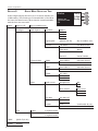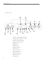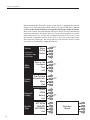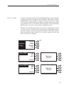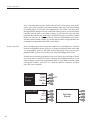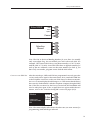
1
Envoy ISDN Codec
SECTION
1 .........INTRODUCTION......................................................................................... 4
........................ENVOY FEATURES .......................................................................... 4
........................WHAT COMES WITH THE ENVOY? ..................................................... 4
........................ABOUT THE ALGORITHM ................................................................. 5
........................TERMINAL ADAPTER ..................................................................... 5
.......................COMMAND PROCESSOR .................................................................. 5
........................UPGRADES .................................................................................. 5
2..........ENVOY MENU SELECTION TREE ................................................................... 6
3..........DIAGRAMS AND DESCRIPTIONS OF CONTROLS AND CONNECTORS .......................... 7
........................TOP SURFACE DIAGRAM ................................................................. 7
........................DESCRIPTION OF TOP SURFACE CONTROLS AND INDICATORS .................... 8
........................REAR PANEL DIAGRAM ................................................................... 10
........................DESCRIPTION OF REAR PANEL CONNECTORS ....................................... 11
4..........SETTING UP THE ENVOY ............................................................................ 13
........................POWER CONNECTIONS ................................................................... 13
........................AUDIO CONNECTIONS ................................................................... 13
........................ABOUT UNBALANCED CONNECTIONS .................................................. 15
........................BEFORE YOU START ....................................................................... 16
5..........CONFIGURING THE ENVOY .......................................................................... 17
........................POWER UP SEQUENCE ................................................................... 17
........................SELECTING THE SWITCH TYPE........................................................... 17
........................ENTERING THE SPIDS ................................................................... 19
........................ENTERING THE LDNS .................................................................... 20
........................CONNECTING THE ISDN LINE ......................................................... 21
........................SELECTING THE DATA RATE ............................................................. 22
........................PLACING A CALL........................................................................... 24
........................PROGRAMMING QDIAL .................................................................. 25
........................LAST NUMBER REDIAL ................................................................... 27
........................RECEIVING CALLS.......................................................................... 27
........................ANCILLARY DATA .......................................................................... 27
........................ISDN LINE PROFILES .................................................................... 28
........................MENUS FOR LOADING AND STORING ISDN PROFILES ............................ 29
6..........ADDITIONAL FUNCTIONS ............................................................................. 31
........................SPECIAL MENU............................................................................. 31
........................STL BACKUP MODE ..................................................................... 32
........................LDM MODE ............................................................................... 33
........................EXTERNAL DCE MODE ................................................................. 34
Comrex Corporation
SECTION
7..........TROUBLESHOOTING.................................................................................... 35
........................CODEC LOOPBACK ........................................................................ 35
........................EXPECTED RESULTS IN CODEC LOOPBACK TEST .................................... 36
........................TA LOOPBACK ............................................................................. 36
........................EXPECTED RESULTS IN TA LOOPBACK TEST.......................................... 37
........................LOOK FOR THE BIG OK ................................................................ 38
........................USING LONG DISTANCE ACCESS CODES.............................................. 39
........................SOME KNOWN SPID FORMATS ........................................................ 40
........................INTERNATIONAL A/C POWER CORDS .................................................. 41
8..........ABOUT ISDN.......................................................................................... 42
9..........ORDERING ISDN..................................................................................... 43
........................ISDN SERVICE ORDER INFORMATION ................................................ 43
........................AT&T 5ESS CUSTOM SWITCH ........................................................ 44
........................DMS-100 NORTHERN TELECOM SWITCH ........................................... 45
........................CHECKLIST FOR ALL SWITCH TYPES .................................................... 45
10........TECHNICAL DETAILS................................................................................... 46
........................G.722 ALGORITHM ...................................................................... 46
........................THEORY OF OPERATION ................................................................. 46
........................SYNCHRONIZATION ........................................................................ 47
........................INVERSE MULTIPLEXING .................................................................. 48
........................ABOUT ANCILLARY DATA ................................................................ 49
........................TROUBLESHOOTING THE ANCILLARY DATA CHANNEL .............................. 51
........................ENVOY SPECIFICATIONS .................................................................. 52
........................ISDN CONNECTION ...................................................................... 52
........................ENVOY PINOUTS ........................................................................... 53
APPENDIX A........ABOUT MIX MINUS ....................................................................... 54
APPENDIX B........FCC REQUIREMENTS ..................................................................... 56
SCHEMATICS
2
Envoy Product Manual
About Comrex
Comrex has been building reliable, high quality broadcast equipment since 1961.
Our products are used daily in every part of the world by networks, stations and
program producers.
Every product we manufacture has been carefully designed to function flawlessly,
under the harshest conditions, over many years of use. Each unit we ship has been
individually and thoroughly tested. Most items are available off-the-shelf, either directly from Comrex or from our stocking dealers.
Comrex stands behind its products. We promise that if you call us for technical assistance, you will talk directly with someone who knows about the equipment and
will do everything possible to help you.
Our toll free number in North America is 800-237-1776. Product information along with
engineering notes and user reports are available on our website at www.comrex.com.
Our E-Mail address is [email protected].
Warranty and Disclaimer
All equipment manufactured by Comrex Corporation is warranted by Comrex
against defects in material and workmanship for one year from the date of original
purchase, as verified by the return of the Warranty Registration Card. During the
warranty period, we will repair or, at our option, replace at no charge a product
that proves to be defective, provided you obtain return authorization from Comrex
and return the product, shipping prepaid, to Comrex Corporation, 19 Pine Road,
Devens, MA 01434 USA. For return authorization, contact Comrex at 978-784-1776
or fax 978-784-1717.
This Warranty does not apply if the product has been damaged by accident or misuse
or as the result of service or modification performed by anyone other than Comrex
Corporation.
With the exception of the warranties set forth above, Comrex Corporation makes
no other warranties, expressed or implied or statutory, including but not limited to
warranties of merchantability and fitness for a particular purpose, which are hereby
expressly disclaimed. In no event shall Comrex Corporation have any liability for indirect, consequential or punitive damages resulting from the use of this product.
Copyright Notice
The Comrex proprietary code and licensed, third party proprietary code residing
in and otherwise associated with this product are protected by copyright law and
international treaties. Unauthorized reproduction or distribution of this product, or
any portion of it, may result in civil and criminal sanctions, and will be prosecuted
to the fullest extent of the law.
US Government Restricted Rights - Use, duplication, or disclosure by the US Government is subject to restrictions set forth in subparagraph (c)(1)(ii) of the Rights
in Technical Data and Computer Software clause at DFARS (48 CFR) 252.227-7013
or subparagraphs (c)(1) and (2) of the Commercial Computer Software-Restricted
Rights clause at FAR (48 CFR) 52.227-19, as applicable.
3
Comrex Corporation
SECTION 1.
ENVOY FEATURES
INTRODUCTION
The Comrex Envoy is an audio transmission device for ISDN digital circuits.
The Envoy includes codec, Terminal Adapter, NT-1 and mixer in a rugged,
lightweight easy-to-use package. Additional features include:
♦ Full duplex 7.5 kHz or 15 kHz audio.
♦ Easy to use dialing and configuring interface.
♦ Available in portable chassis. Compatible with the Comrex Nexus,
DXR.1, DXP.1 and Matrix ISDN codecs as well as most other
manufacturers’ G.722 ISDN codecs.
♦ Automatically rate adapts to answer ISDN calls at 56, 64, 112 or 128 kb/s.
♦ Two contact closures — one upon connection and one for triggering
STL Backup Mode.
♦ Ancillary data channel of 4800 baud allows a user to pass data
between two computers (great for call screening or delivering
sports scores).
♦ Ability to store 20 telephone numbers and last number dialed in
nonvolatile memory.
♦ 6 mS coding delay allows seamless two-way communication.
♦ Four channel microphone mixer (2 channels mic/line selectable).
♦ Three headphone outputs (adjustable mix of send/receive audio).
♦ Balanced line level audio out (adjustable mix of send/receive audio).
♦ Input and output kill buttons.
♦ Spotter/producer input.
WHAT COMES WITH
AN ENVOY?
The following items are shipped with a new Envoy:
(1) Comrex Envoy ISDN codec
(1) A/C power module with A/C cord
(1) RJ11C modular telephone cord
(1) Operating manual
(1) Warranty card (Please fill out and return.)
4
Envoy Product Manual
ABOUT THE ALGORITHM
Codec is an acronym for Coder/Decoder. We define this as the part of the
Envoy which takes in an analog audio signal, converts it to a digital bit stream,
and performs operations on this bit stream to remove redundant information.
This operation is known as Digital Audio Compression. The codec section
also takes an incoming, previously compressed bit stream and converts it to
analog audio. In the Envoy codec, the analog audio inputs and outputs are
available to the user. The input and output compressed bit streams are connected internally to the terminal adapter section. There are different types
of compression, and the type is often defined by the name of the algorithm
employed. The Envoy uses the international standard G.722 algorithm, and
it is also capable of a higher speed version of G.722 which provides 15 kHz
bidirectional audio at 112/128 kb/s. For more information on this subject, see
the “G.722 Algorithm” section on page 46.
TERMINAL ADAPTER
We call this the “TA” for short. This section can be thought of as a modem, but
one that only works on a special type of telephone line. This line is called an
Integrated Services Digital Network line, or ISDN. A description of this service is included on page 42. The TA takes the encoded audio from the codec
and feeds it to the telephone line. It also feeds audio data from the phone
line to the codec. It allows you to dial and answer ISDN phone calls and
provides the functions required to “handshake” with the ISDN line as well as
to troubleshoot problems should they occur. The TA in the Envoy includes a
section called the NT1 which is a conditioning circuit that interfaces with the
phone line. This eliminates the requirement for another external box on your
circuit. The Envoy TA also can combine the two ISDN “B” channels using an
inverse multiplexing standard called BONDING. This allows for a transmission rate of 112/128 kb/s on ISDN. For more information on this subject, see
the “Inverse Multiplexing” section on page 48.
COMMAND PROCESSOR
This is the “brain” of the Envoy. It communicates with the codec and TA, sets
them to the correct modes and provides the user interface for configuring
and dialing the TA. It also provides the ancillary data function and allows you
to communicate to the TA via computer.
UPGRADES
A substantial portion of the functions and features of the Envoy is software
driven, which will allow upgrades to these units by a simple exchange of
EPROMs. We will keep our customers apprised of software updates and make
these available at no charge. In order to assure that we will be able to contact
you, please be sure to return the warranty card with complete address and
contact information.
5
Comrex Corporation
SECTION 2.
ENVOY MENU SELECTION TREE
In this sample display, the Envoy is set to dial at 128 kb/s (for
15 kHz audio). The switch type is National ISDN 1. The OK in
the lower left hand corner shows that the initial handshake
with the line was successful.
Menu
Place a Call
Key in number now
Configure
Dial Options
Network Info
More
Test
6
QDial
Qdial # (01-20)
Redial
Dialing
Status
♦Switch NI-1
♦Data Rate 128K
Menu
Q Dial
Redial
OK
Data Rate
56Kb\s
64Kb\s
112Kb\s
128Kb\s
Prgrm Qdial
Qdial # (01-20)
Key in number now
Special
STL Mode
STL Mode Active
Ldm Mode
Master
Slave
Ext DCE
Ext DCE Mode
SPIDS
Enter SPID 1
Enter SPID 2
Selection Stored
Selection Stored
LDNS
Enter LDN 1
Enter LDN 2
Selection Stored
Selection Stored
Switch
ATT 5ESS
DMS100
Nat ISDN 1
Audio in\out
Headphones
Mix
Split
Mute Switch
Mute Local
Mute Rtrn
Mute Both
Anc Data
Anc Data off
Anc Data on
Profiles
Load
Store
Codec
Loopback Active
TA
Loopback Active
Load Profile # (1-9)
Store Profile # (1-9)
Envoy Product Manual
SECTION 3.
DIAGRAMS AND DESCRIPTIONS OF CONTROLS AND CONNECTORS
TOP SURFACE DIAGRAM
1) INPUT LEVEL CONTROLS 1, 2 & 3
8) MENU SOFTKEYS
2) RETURN AUDIO LEVEL FOR HEADPHONES 1, 2 & 3
9) MUTE AUDIO IN BUTTON
3) LOCAL AUDIO LEVEL FOR HEADPHONE 1, 2 & 3
10) DIALING KEYPAD
4) HEADPHONE JACKS 1, 2 & 3
11) MUTE AUX OUT BUTTON
5) READY INDICATOR
12) AUX INPUT LEVEL CONTROL
6) CARRIER DETECT (CD) INDICATOR
13) RETURN AUDIO LEVEL FOR AUX OUT
7) VU METER
14) LOCAL AUDIO LEVEL FOR AUX OUT
7
Comrex Corporation
1
INPUT LEVEL CONTROLS
1, 2 & 3
These knobs control the input audio level for audio channels 1, 2 and 3 respectively. The knobs are color coded. Adjust each mixer channel using these
knobs until an appropriate indication is achieved on the VU meter.
2
RETURN AUDIO LEVEL
FOR HEADPHONES
1, 2 & 3
These knobs determine the level of the audio on each headphone that is received from the other end of the link. Adjust these knobs until a comfortable
listening level is achieved. If you do not wish to hear any return audio on any
particular headphone, turn that control all the way down. The headphone
control knobs are color coded to coincide with the input level controls.
3
LOCAL AUDIO LEVEL FOR
HEADPHONE 1, 2 & 3
These knobs determine the level of the audio on each headphone that is generated locally within the Envoy. This includes all the mics and other sources
plugged into the Envoy as well as the aux input, if it is set up as a producer
or spotter feed. Adjust this knob until a comfortable listening level is achieved
on the headphones. If you do not wish to hear any local audio on any particular headphone, turn that control all the way down. The headphone control
knobs are color coded to coincide with the input level controls.
Note: The headphones can be set up two different ways in the menu system.
The first option is to hear the same mix of local and return audio in both
sides of each headphone. The second option allows for a “split feed,” where
the local audio is heard in the left side of the headphones only, and the
return audio is only heard in the right side. See page 14 to configure.
8
4
HEADPHONE JACKS
1, 2 & 3
These are 3 conductor 1/4 inch headphone jacks (suitable for most stereo
headphones).
5
READY INDICATOR
This is a signal from the digital audio decoder which signifies it has locked
onto the incoming digital audio signal. This will usually light up a few seconds
after connection and will go out if the codec “loses sync” for any reason. A
contact closure which follows this indication is available on the rear panel.
6
CARRIER DETECT (CD)
INDICATOR
When the Envoy receives an incoming call, this carrier detection light will be
on steady indicating that the terminal adapter has established a connection
with another compatible codec. At this point, audio is not yet being encoded
and decoded.
7
VU METER
This provides an indication of the audio level being fed into the Envoy. It
doesn’t mirror the receive audio in any way. Most users set input level so the
VU peaks just over the “0” mark, which is the yellow LED on this meter.
Envoy Product Manual
8
MENU SOFTKEYS
These work like the buttons on an Automatic Teller Machine. Depending
on your menu selection, one or more of the keys will offer you the different
choices in that menu.
9
MUTE AUDIO IN
This is a toggle switch which kills all audio going into the Envoy when activated.
It can be used as a “cough” switch or simply a way to keep your conversations
private during a break. When this button is depressed, the VU meter will no
longer show the input audio level for any input channel.
10 DIALING KEYPAD
Use this keypad to place calls with the Envoy.
11 MUTE AUX OUT
This is a toggle switch which will kill the audio feed provided on the AUX OUT
audio output on the rear panel. Like the headphone channels, this line level
output is a user-adjustable mix of local and return audio. This button can be
configured via the menu to mute only the return audio, only the local audio,
or both. This can be useful when the Envoy is connected to a PA system at a
remote venue, and you don’t want some programming to be heard over the
PA. See “Auxilliary Output” on page 15 to configure this button.
12 AUX INPUT LEVEL CONTROL
This knob determines the input level for the audio at the AUX IN connector. If
this connector has been configured to be a main program channel, the level
will appear on the VU meter. If the AUX IN has been configured as a producer/
spotter channel, no VU indication will appear, but the level control still adjusts
this level into the headphones. You may wish to set this level with the channel
configured in the “program mode,” then switch it to the “spotter/producer”
mode, if desired. (See “Input 4” on page 13 for details.)
13 RETURN AUDIO LEVEL
FOR AUX OUT
This knob controls the level of the audio present on the AUX OUT connector
that is sent from the far end of the link. If you do not wish to hear any return
audio from this output, turn the knob all the way down. The knob is color
coded to coincide with the AUX IN knob.
14 LOCAL AUDIO LEVEL
FOR AUX OUT
This knob controls the level of the audio present on the AUX OUT connector
that is locally mixed within the Envoy, including channels 1-3 and AUX IN if it
is configured as a program channel.
9
Comrex Corporation
REAR PANEL DIAGRAM
15) CHANNEL 1 INPUT MICROPHONE CONNECTOR
16) CHANNEL 2 INPUT MICROPHONE CONNECTOR
17) CHANNEL 3 INPUT CONNECTOR
18) POWER CONNECTOR STRAIN RELIEF
19) CHANNEL 3 MIC/LINE SWITCH
20) POWER JACK
21) STL CLOSURE
22) READY CLOSURE
23) ISDN “U” INTERFACE
24) ANCILLARY DATA
25) AUX OUT CONNECTOR
26) AUX IN MIC/LINE SWITCH
27) AUX IN CONNECTOR
28) AUX IN CONTROL SWITCH
29) EXTERNAL DCE
30) POWER SWITCH
10
Envoy Product Manual
15&16 CHANNEL 1 & 2
INPUT MIC CONNECTORS
These 3 pin female XLR connectors are designed to accept balanced, microphone level audio feeds. The input level for these channels is adjustable via
the knobs in the left and middle positions as shown in #1 of the Top Surface
diagram on page 7.
17
CHANNEL 3
INPUT CONNECTOR
This 3 pin female XLR connector is designed to accept a balanced, microphone
or line level audio feed. The input level for this connector is adjustable via the
top surface control in the right position as shown in #1 of the Top Surface
diagram on page 7. The level is selectable between nominal mic or line level
via the associated switch (see #19).
18
POWER CONNECTOR
STRAIN RELIEF
This built in clip is designed to sit over the cord feeding the power connector,
providing protection against the connector pulling out if someone should
tug on the cord. To use it, simply feed the power cable under the clip before
connecting it to the Envoy.
19
CHANNEL 3
MIC/LINE SWITCH
This switch determines whether audio input #3 is configured to receive a microphone level (-80 to -40 dBu) or line level (-10 to +4 dBu) audio input.
20
POWER JACK
This is a 2-conductor barrel connector designed to mate with the Envoy
power supply module. Be sure to attach only the power supply provided
from Comrex here. The Envoy requires 5V on this connector.
21
STL CLOSURE
This mini jack is a dry contact closure which triggers closed when the Envoy
is in STL BACKUP MODE.
22
READY CLOSURE
This mini jack provides a dry contact closure when the digital audio decoder
achieves synchronization with an incoming digital audio signal— i.e., when
the decoder is decoding audio. This closure follows the READY light next to
the front panel display.
23
ISDN "U" INTERFACE
This RJ-11C modular jack is for attaching the ISDN line from the outside
world to the Envoy.
24
ANCILLARY DATA
This 9 pin female connector provides connection for a 4800 baud ancillary
data channel enabling data communications while broadcasting.
25
AUX OUT CONNECTOR
This 3 pin male XLR output provides a mix of codec return and local audio
from the Envoy. It is a balanced, line level audio feed, whose level is adjustable via the AUX OUT RETURN and AUX OUT LOCAL knobs on the top surface. Suitable
for connection to a PA system, it can be selectively muted via the top surface
MUTE AUX OUT control (see “Auxilliary Output 4” on page 15).
11
Comrex Corporation
12
26
AUX IN MIC/LINE SWITCH
When this switch is “up,” the AUX IN connector (#27) is configured to receive
a microphone audio level (-80 to -40 dBu). When this switch is “down,” the
AUX IN is configured to receive a line level (-10 to +4 dBu). At either setting,
the level is adjustable via the AUX IN control knob on the top surface.
27
AUX IN CONNECTOR
This is a 3 pin female XLR connector suitable for balanced mic or line level
audio (dependent on the setting of switch #26). It can be used as a main
program channel or as a spotter/producer input (dependent on the setting
of switch #28).
28
AUX IN CONTROL SWITCH
If this switch is “up,” the audio present at the AUX IN connector is not heard on
air. Instead, it is heard only in the headphones. This is useful if a producer or
spotter is present who is to be heard only by the people on-air. If this switch
is “down,” AUX IN becomes a 4th program channel and functions just like the
channel 3 input.
29
EXTERNAL DCE
This port allows you to bypass the terminal adapter inside the Envoy and
connect to an external terminal adapter, DSU, satellite terminal, etc.
30
POWER SWITCH
0 = off, 1 = on. These markings are screened directly on the rocker switch.
Envoy Product Manual
SECTION 4.
SETTING UP THE ENVOY
POWER CONNECTIONS
Attach the external power supply to the connector on the rear panel marked
“power.” If you wish, route this cable under the plastic clip to provide a
strain relief. Attach the provided AC power cord to the power supply, and
apply AC power. Turn the Envoy on using the rear panel power switch (0
= off and 1 = on). The Envoy display should light up. You will then see the
introductory screen followed shortly by the status screen. See page 17 to
view this screen.
AUDIO CONNECTIONS
Inputs 1, 2 & 3 — The Envoy has four inputs. First we will tackle channels 1
and 2, which are microphone level only inputs. As you look at the unit from
the rear, these are the 3 pin female XLR connectors farthest to the right. Both
channels operate the same way. Connect your microphone to either of these
XLRs, and adjust your input level via the channel 1 or 2 input level control
on the top surface. The input level will be reflected on the VU meter. Most
users like to see a VU meter peak occasionally over the “0” mark, which is
the yellow LED on this meter. If you cannot achieve a good input level, make
sure the top surface button labeled MUTE AUDIO INPUTS is disengaged (no red
showing). If that doesn’t work, you will need to try a different microphone
or cable. These inputs do not support microphones which require phantom power. Channel 3 input works much the same way, but you can select
whether you wish to feed a microphone or line level source into this input.
If you are connecting a microphone, the switch next to the channel 3 input
connector must be up. Otherwise, set the switch down and feed a balanced
line level into the connector. If your source is unbalanced, read the section
“About Unbalanced Connections” on page 15. In any case, you will control
the input level with the top surface Channel 3 input level knob until you get
a good reading on the VU meter.
Input 4 — Channel 4 has more options than the others. To get started, set the
control switch furthest to the left on the rear panel to the “down” position.
This will make channel 4 a regular program channel. Now select whether you
will be feeding a mic or line level input into channel 4, and set the channel
4 mic/line switch appropriately. Now feed some typical audio into channel 4,
and adjust the level on the VU meter using the channel 4 input level control
on the top surface. If you plan on using channel 4 as a regular program channel, you’re done with your input audio setup. If you’d like to use channel 4
as a spotter or producer input, move the control switch (the one on the far
left) to the “up” position. Channel 4 will now not be heard on-air or seen on
the VU but can be heard in the headphones.
13
Comrex Corporation
Headphone Outputs 1, 2 & 3 — All work the same way so we’ll describe
headphone 1 operation and you can take it from there. First you must determine whether you want the headphone audio to be SPLIT or MIXED. The Envoy
headphone outputs feed the user two different audio sources — the first is
called RETURN which is all the audio being sent from the other end of the link.
The second is called LOCAL and contains all the microphone or line level inputs
connected to the Envoy itself. The Envoy can be configured to “split” the two
sources by feeding local audio into the left headphone and return into the
right, or it can “mix” the two sources by feeding both left and right with the
same mix. Only one selection is allowed for all three headphones. If you won’t
be listening to one of the audio sources, we recommend the MIX option so the
remaining source will be fed to both headphone ears.
To select an option, press the MENU softkey on the status display to access the
main menu. Now select CONFIGURE. From the config menu, select MORE. Now select
AUDIO IN\OUT. Then choose HEADPHONES. Select the MIX or SPLIT options here. Your
choice will remain in memory until it is changed, even after the power is off.
You must have stereo headphones to use with the Envoy. Plug the headphones
into the # 1 headphone jack. Feed some audio into one of the inputs and get
a good level on the VU meter. Turn both headphone controls (LOCAL and RETURN)
for channel 1 all the way down. First we’ll set the level for the return audio,
then the local. Press the MENU softkey on the status display to access the main
menu. Now press TEST. Select either loopback test (If you have chosen the codec
loopback test, the READY light next to the display should now come on; if you have
chosen the TA loopack test, the READY and CD lights next to the display should
now come on). Now turn up the channel 1 knob (farthest column on the left)
labeled RETURN until you hear the audio clearly. When finished, press EXIT until
you return to the status display. You have now set the correct headphone level
for the audio which will come to you from the other end of the link. To adust
the listening level of the local audio, turn the headphone control lableled LOCAL until you get a comfortable listening level while audio is being fed into the
Envoy. Your headphone adjustment is complete. Feel free to adjust LOCAL and
RETURN after a connection is made to achieve the right balance and overall level.
Headphones 2 and 3 are adjusted the same way. In some situations, you may
wish to hear only LOCAL or only RETURN audio in a particular headphone. Simply
turn the unwanted audio control for that headphone all the way down.
Note: Loopback tests and their functions beyond setting the headphone levels
are explained on pages 35-37.
14
Envoy Product Manual
Auxiliary Output 4 — There is one line level audio output on the Envoy
labeled AUX OUT. Like the headphone outputs, this is an adjustable mix of LOCAL and RETURN audio, but it is at a balanced line level on a 3 pin male XLR.
The XLR connector is on the rear panel of the Envoy, and the LOCAL and RETURN
level controls are on the top surface. Use the same procedure outlined in the
headphone section to set the correct levels at this port.
The audio feed from this output can be muted by pressing the MUTE AUX OUT
button, but first you must select whether the return audio, local audio or
both should be muted. To do so, press MENU from the status display. Then
press CONFIGURE, and choose MORE. Next select AUDIO IN/OUT. Press MUTE SWITCH,
and decide which audio you wish to mute. The current selection will remain
in memory until changed (even when powered off) and will be muted when
the MUTE AUX OUT button is depressed.
ABOUT UNBALANCED
CONNECTIONS
It is best when using professional audio gear to connect everything together
using balanced audio connections. Sometimes, however, it is unavoidable to
connect to consumer equipment with unbalanced connections. If you must
use unbalanced audio, here’s how to connect to the Envoy:
Envoy inputs — When driving the Envoy from an unbalanced source, connect pins 1 and 3 together on the Envoy input XLR. This gets connected to
the ground signal on your unbalanced device. Connect pin 2 on the Envoy
XLR to the unbalanced device’s audio + connection.
Envoy outputs — The Envoy uses active balanced outputs designed to drive
unbalanced sources directly. This means there won’t be any level difference
when feeding an unbalanced source. On the Envoy output XLR, connect pins
1 and 3 together, and tie this to ground on your unbalanced device. Tie pin
2 on the Envoy XLR to audio + on the unbalanced device.
15
Comrex Corporation
BEFORE YOU START
The following information has to be programmed into the Envoy before it is
connected to an ISDN line and each time it is moved to a new line.
Switch type
SPID numbers (Service Profile IDentifiers)
Local dialing numbers (LDNs)
This data is provided by the telephone company, and it is unique to the specific
ISDN line to which you are connecting. Do not let your ISDN installer leave
without being certain that you have the correct information in hand. Otherwise,
it can result in the Envoy not working at all, or “partially” working and can require time-consuming troubleshooting. Incorrect phone company information
is the number one source of difficulty when configuring ISDN equipment. The
second is incorrectly installed phone lines, which we deal with in the “Look for
the Big OK” section on pages 38-39.
The switch type, SPID, and local phone numbers need to be programmed into
the Envoy before it is attached to the ISDN line. If you reenter any of these
values once the Envoy has “shaken hands” with the line, disconnect the Envoy
from the line temporarily or power it down momentarily in order to initiate a
new “handshake.” Any information entered into the Envoy will be saved if it is
turned off or loses power, so you will not need to reprogram the line information unless you move it to another ISDN line.
Note: If you are installing the Envoy for a full time application, we recommend
protecting it with an uninterrruptible power supply (UPS) with built in surge
protection. A model in the 250 watt category should be fine, and prices are
now less than $100. They are available from computer and electronic stores.
16
Envoy Product Manual
SECTION 5.
POWER UP SEQUENCE
CONFIGURING THE ENVOY
When the Envoy is connected to power and turned on, the self test menu
appears for approximately thirty seconds. The Envoy then shows the status
display. The main setup options are displayed in the lower left portion of
the screen. As shipped from the factory, the Envoy status display will be the
same as the screen shown below. These selections will remain in nonvolatile
memory until changed.
Self Test
♦
♦
♦
Status
♦Switch NI-1
♦Data Rate 128K
♦
♦
Menu
Q Dial
Redial
Link Down
SELECTING THE SWITCH TYPE
The telephone company will need to tell you the switch type so you can select
it here. This describes the type of equipment on the telephone company’s end
of the ISDN line. The choices are AT&T 5ESS, Northern Telecom DMS100, and
National ISDN 1 (NI1). Note that the AT&T and Northern Telecom switches
often work in NI1 mode, so if this is the case NI1 is the correct choice. 5ESS
or DMS100 should be selected only if the telephone company has specified
these custom configurations for your line. If in doubt about this choice,
contact the company that installed your ISDN line. Refer to the next page to
program the switch type into the Envoy.
17
Comrex Corporation
Before attaching the ISDN line, power up the Envoy by plugging the external
supply to A/C and turning the switch on the rear panel of the Envoy. Do not
connect to the ISDN line before entering the switch type, SPIDs and LDNs.
After a few seconds, the status display will appear. Don’t be concerned with the
Link Down message at this point. Press MENU on the status display to access the
main menu. Press CONFIG to select the configuration menu. Press NETWORK INFO for
the network configuration menu. Press SWITCH to enter the switch type menu.
Then select the switch type. The Envoy will store your selection. Press EXIT until
you return to the network configuration menu.
Status
♦Switch NI-1
♦Data Rate 128K
Menu
Q Dial
Redial
⇐
Link Down
Main
Menu
Config
Menu
Network
Config
Switch
Type
18
Place a Call
Configure
Test
Exit
⇐
Dial Options
Network Info
More
Exit
⇐
SPIDS
LDNS
Switch
Exit
ATT 5ESS
DMS100
NAT ISDN 1
Exit
⇐
Selection
Stored
Envoy Product Manual
ENTERING THE SPIDS
You will now program the exact Service Profile ID Number that the telephone
company gave you for each channel of your ISDN line. This number is used to
handshake between the telephone company and the Envoy. Press SPIDS while
in the network configuration menu to begin entering the SPIDs. After SPID 1
is programmed, press OK. The SPID 2 menu will appear. After programming
SPID 2, press OK to return to the network configuration menu.
If SPIDs were previously programmed into your Envoy, they will appear. If they
are correct, press OK until you return to the network configuration menu. If
you wish to change a previously programmed SPID or if you make a mistake
while entering the number, press BACK SPACE until the number is cleared, and
then enter the correct number.
Network
Config
Enter SPID 1
SPIDS
LDNS
Switch
Exit
⇐
OK
Back
Space
Selection
Stored
Cancel
Enter SPID 2
OK
Back
Space
Selection
Stored
Cancel
19
Comrex Corporation
Note: Some ISDN lines use two SPIDs, some use one, and some use none at all.
Often, your SPID resembles your phone number plus area code with leading
or trailing digits. If your line was configured for two SPIDs, you must enter
the appropriate numbers exactly as they have been given to you by the phone
company into the SPID 1 and SPID 2 menus. If your line has only one SPID,
program that number into both SPID 1 and SPID 2 menus. If you have ordered
service on only one “B” channel (1B+D), enter the SPID number into SPID 1
and leave SPID 2 blank. Finally, if your line has no SPIDs, verify that there are
no numbers programmed into SPID 1 and SPID 2.
ENTERING THE LDNS
Now you will program the local phone numbers for your ISDN lines. From the
network configuration menu, press LDNS to begin entering the LDNS. After LDN
1 is programmed, press OK. The LDN 2 menu will appear. After you have programmed LDN 2, press OK to return to the network configuration menu.
If LDNs were previously programmed into your Envoy, they will appear. If they
are correct, press OK until you return to the network configuration menu. If you
wish to change a previously programmed LDN or if you make a mistake while
entering the number, press BACK SPACE until the number is cleared, and then
enter the correct number.
Network
Config
Enter LDN 1
SPIDS
LDNS
Switch
Exit
OK
Back
Space
Cancel
20
⇐
Selection
Stored
Envoy Product Manual
Enter LDN 2
OK
Back
Space
Cancel
Selection
Stored
Note: The LDN is the Local Dialing Number for your line. It is usually
only seven digits long. Do not include your area code in the LDN. For
example: The Comrex ISDN Envoy test phone number is 978-772-9404,
and the LDN is 772-9404. Some ISDN lines have a different number for
each of the two channels, some use the same number for both. If you
have only one number, program it into both the LDN menus.
CONNECTING THE ISDN LINE
After the switch type, SPID, and LDN are programmed correctly, press the
EXIT key until you are again at the status menu. Now, attach the ISDN line
to the telephone connector on the rear of the Envoy. In about one minute,
the LINK DOWN status display should change to OK. This means that the Envoy
has correctly “shaken hands” with the telephone company along the ISDN
line. If the line is removed or the Envoy is turned off, this handshake will
need to take place again. If the OK signal does not appear within about a
minute, refer to the “Look for the Big OK” section on pages 38-39.
Status
♦Switch NI-1
♦Data Rate 128K
Menu
Q Dial
Redial
OK
Note: The status display also shows the data rate (see next section for
programming) and switch type selected.
21
Comrex Corporation
SELECTING THE DATA RATE Now that the Envoy has been set up for your ISDN service, you will need to tell
it a few things about what you want to accomplish. The first selection will be
data rate. The Envoy can communicate at four different data rates: 56, 64, 112
or 128 kb/s. The 56 or 64 kb/s data rates use only one “B” Channel, and you
will only be billed for one ISDN phone call at these rates. The 112 and 128 kb/s
rates actually place two different calls between points using both “B” Channels
(although it looks to you like one call is placed), and you will be billed for twice
the connect charges.
Audio bandwidth varies with data rate. At 56 and 64 kb/s, the Envoy carries 7.5
kHz audio bandwidth. This is nearly transparent audio for voice applications,
although you might notice a slight cutoff at the “ss” sound in voices. At 112 or
128 kb/s, the Envoy carries through 15 kHz audio, providing full, FM radio quality bandwidth for voice and music. There is little perceivable difference between
56 and 64 kb/s (as well as 112 and 128 kb/s). The 56 and 112 kb/s rates are
provided for compatibility with ISDN lines which do not provide clear channel
64 kb/s transmission and also to interwork with Switched 56 systems. If you
are using ISDN on both ends of your system, you should attempt to connect
first at 64 (or 128) kb/s, and if you experience problems, try backing down to
56 (or 112) kb/s.
To select your data rate, press MENU on the status display to access the main
menu. Press CONFIG to select the configuration menu. Select DIAL OPTIONS for the
dialer configuration menu. Press DATA RATE to enter the data rate menu. Select
the data rate you want to use. The Envoy will store your choice and retain it in
memory even if the unit is powered off. Return to the status display by pressing
EXIT. Under most circumstances, two Envoys (or an Envoy and a Nexus) which
are set to different data rates will negotiate down to the setting of the lowest
unit (however, this feature is dependent on the network and may not always
work). This allows for a unit which accepts incoming calls to be set to 128 kb/s
and automatically adjust to take calls from units set to lower rates.
Status
♦Switch NI-1
♦Data Rate 128K
OK
22
Menu
Q Dial
Redial
⇐
Envoy Product Manual
SELECTING THE DATA RATE
Place a Call
Configure
Test
Exit
Main
Menu
Config
Menu
Dial Options
Network Info
More
Exit
Dialer
Config
Data Rate
Prgrm Qdial
Special
Exit
Select a
Data
Rate
(Press
# to
Cancel)
56Kb\s
64Kb\s
112Kb\s
128Kb\s
⇐
⇐
⇐
Selection
Stored
23
Comrex Corporation
PLACING A CALL
There are two ways to place a call with the Envoy. You can dial manually or use
the Quick Dial option for automatic dialing. To manually dial, select MENU from
the status display. Press PLACE A CALL from the main menu, and key in the number
you wish to call. Press the OK key to start dialing. If you make a mistake, simply
press BACK SPACE until the number is cleared and, then enter the correct number.
If at any point you wish to terminate the call, simply press the HANGUP key.
Status
♦Switch NI-1
♦Data Rate 128K
Menu
Q Dial
Redial
⇐
OK
Main
Menu
Place a Call
Configure
Test
Exit
Key in number now
OK
⇐
⇐
Back
Space
Cancel
Note: ISDN dialing numbers use the same local and international access and
area codes as normal analog calls, i.e. if you use a “1” before a number for
a normal long distance call, use a “1” before the ISDN number.
24
Envoy Product Manual
To place a QDial call, simply press the QDIAL key on the status menu, and then
enter the QDial number (01-20) that you wish to dial. Your call will complete
momentarily. Programming QDial is discussed below.
Menu
Q Dial
Redial
Status
♦Switch NI-1
♦Data Rate 128K
⇐
OK
Qdial # (01-20):
Cancel
PROGRAMMING QDIAL
The Envoy has 20 memory locations which allow you to store a number and
dial it quickly using the QDIAL button. To program your QuickDial memory,
press MENU on the status display. Then press CONFIGURE in the main menu, followed by DIAL OPTIONS in the config menu. Next, select PRGRM QDIAL from the
dialer config menu. Enter your memory index number (01-20), and then input
the dialing number. If a number was programmed into that Qdial location
previously, it will appear. You may erase the number (or backup if you make
a mistake) using the BACK SPACE key. Press OK when your number is complete.
Press EXIT until you reach the status display. The QDial numbers will remain
in memory, even if the Envoy loses power.
Status
♦Switch NI-1
♦Data Rate 128K
Menu
Q Dial
Redial
⇐
OK
25
Comrex Corporation
PROGRAMMING QDIAL
Main
Menu
Place a Call
Configure
Test
Exit
Config
Menu
Dial Options
Network Info
Test
Exit
Dialer
Config
Data Rate
Prgrm Qdial
Test
Exit
⇐
⇐
⇐
Qdial # (01-20):
Cancel
Key in number now
OK
Back
Space
Cancel
26
⇐
Envoy Product Manual
LAST NUMBER REDIAL
Redialing the last number is easy – either press the REDIAL key on the status
display or the QDIAL key and 00. The last number you dialed from the Envoy
will be redialed. This number will remain in memory after the Envoy is powered down.
RECEIVING CALLS
As long as your options are set to be compatible with the incoming device,
the Envoy should automatically answer the incoming call and “wake-up,”
providing full duplex audio.
ANCILLARY DATA
Ancillary data provides a low speed data channel along the same ISDN phone
call used for the coded audio. It has little impact on the audio quality and
allows two computers (or other asynchronous devices) to communicate at
4800 baud. The 4800 baud rate is fixed regardless of the data rate selected.
The one thing to note about ancillary data is that both Envoys or an Envoy
and a Nexus MUST be configured the same way with ancillary data on or off.
If the ancillary data mode is mismatched between two Envoys or an Envoy
and a Nexus, the audio channel will not work correctly. If communicating to
a compatible device which is not an Envoy or Nexus, the ancillary data mode
must always be off.
To set this mode, select MENU from the status display. Then select CONFIGURE
from the main menu. From the config menu choose MORE. Then select ANC
DATA. Finally, select ANC DATA ON or ANC DATA OFF. If you have selected ANC DATA ON,
this will be indicated on the status display. Press EXIT until you return to this
display. Configuration and connection of ancillary devices is covered in the
“About Ancillary Data” section on pages 49-51.
Status
♦Switch NI-1
♦Data Rate 128K
Menu
Q Dial
Redial
⇐
OK
Main
Menu
Place a Call
Configure
Test
Exit
⇐
27
Comrex Corporation
Config
Menu
Dial Options
Network Info
More
Exit
Config
Menu
Audio in\out
Anc Data
Profiles
Exit
Anc
Data
⇐
⇐
Anc Data off
Anc Data on
Exit
ISDN LINE PROFILES
For some users who carry their Envoy between different ISDN equipped locations,
it can become difficult and confusing to reprogram all the necessary information
about the ISDN line into the Envoy each time it is moved. The Envoy eases this
task, by allowing you to create nine “profiles” for ISDN lines, which simply need
to be “loaded” at each location.
Begin by setting all the Envoy parameters (SPIDs, LDNs, switch type, data rate
and ancillary data) for a particular venue (pages 17-23 & 27-28). Make sure that
this information is entered correctly before storing the profile. Then select MENU
from the status display, followed by CONFIGURE from the main menu. In the config
menu, choose MORE. Next select PROFILES for the profiles menu. To store the profile,
press STORE and choose a profile index number (1-9). The Envoy will automatically
store all of the preset parameters.
To load the stored profile, follow the above instructions to reach the profiles menu.
Once in the profiles menu, select LOAD and then the appropriate profile index
number (1-9). The Envoy will automatically load all of the preset parameters.
28
Envoy Product Manual
MENUS FOR LOADING
AND STORING ISDN LINE
PROFILES
Status
♦Switch NI-1
♦Data Rate 128K
Menu
Q Dial
Redial
⇐
OK
Main
Menu
Place a Call
Configure
Test
Exit
⇐
Config
Menu
Dial Options
Network Info
More
Exit
⇐
Config
Menu
Audio in\out
Anc Data
Profiles
Exit
⇐
Profiles
Load
Store
Exit
29
Comrex Corporation
Choose Load or Store and the screen will look like one of the two below. Once
you have selected a profile number, the screen will store/load all of the preset
parameters.
Store Profile # (1-9)
Cancel
Load Profile # (1-9)
Cancel
Repeat all of the above steps to store and load multiple profiles. You may wish
to attach a label to the Envoy indicating which profile index number applies to
which ISDN location.
30
Envoy Product Manual
SECTION 6.
SPECIAL MENU
ADDITIONAL FUNCTIONS
The Envoy has three “special” operational modes: STL Backup Mode, Limited
Distance Modem Mode and External DCE Mode. To access these modes press
MENU on the status display. Then select CONFIGURE in the main menu, followed
by DIAL OPTIONS in the config menu. Next press SPECIAL in the dialer config menu.
Choose the appropriate mode from the special modes menu. These modes
are explained in detail after the diagrams.
Status
♦Switch NI-1
♦Data Rate 128K
Menu
Q Dial
Redial
⇐
OK
Main
Menu
Place a Call
Configure
Test
Exit
Config
Menu
Dial Options
Network Info
More
Exit
Dialer
Config
Data Rate
Prgrm Qdial
Special
Exit
Special
Modes
STL Mode
Ldm Mode
Ext DCE
Exit
⇐
⇐
⇐
Note: While these special modes are engaged, the other menus are disabled.
For this reason you will want to make sure all settings are correct before
you enter any “special” mode.
31
Comrex Corporation
STL BACKUP MODE
This mode allows the Envoy to automatically dial the number stored in QDial
01. Select STL MODE from the special modes menu once all your Envoy options
(kb/s, ancillary data, etc.) have been set.
The Envoy will dial Qdial 01 when the STL mini jack on the rear panel of the
Envoy is closed. It will disconnect when the contact closure is opened or STL
Backup mode is exited. If the Envoy should lose power while in STL Backup,
it will return to this mode when power is reapplied.
STL Backup mode is also useful in providing “fail-safe” remote operation.
Simply close the STL mini jack on the rear panel of the Envoy. When ready
to place a call, enter STL Backup mode (having preset all the Envoy parameters). The Envoy will immediately dial Qdial 01 and connect. If at any point
the connection should be lost, the Envoy will detect this and immediately
redial the number. When the call is to be disconnected, exit STL Backup
mode. The contact closure will have no effect on operation other than STL
Backup mode.
Special
Modes
STL Mode
Ldm Mode
Ext DCE
Exit
STL Mode Active
Exit
32
⇐
Envoy Product Manual
LDM MODE
The Envoy has the ability to operate as a Limited Distance Modem (LDM) on
a “dry pair,” or plain old copper wire pair. This can be useful when connecting two local points where ISDN is not available but unloaded and unequalized telephone loops (pairs of wires) are. This mode is not for use on plain
old “subscriber” telephone lines. The service must be a simple pair of wires
running from point A to point B (these may exist already within your local
telephone plant, or may be purchased from the phone company as an unequalized broadcast loop, or simply as an “alarm pair”). There is a distance
limitation in this mode, and it depends on the gauge of wire used and other
environmental factors. In general, use 18,000 feet as a limit when using typical telephone gauge wire.
In this mode, one of your Envoys (or a Nexus if that is what you are connecting with) will be configured as the “Master” (this Envoy/Nexus provides
the clocking signal to the wire) and the other as a “Slave” (this Envoy/Nexus
uses the clocking signal on the wire). The units will provide a completely
independent wideband audio channel in each direction on the single pair
of wires.
To enter LDM mode, select LDM MODE from the special modes menu. It doesn’t
matter which unit you configure for MASTER or SLAVE, only that one is programmed
as each. Now you can attach the wire pair to the Envoy/Nexus as you would
an ISDN line, using the center two pins of the RJ-11 connector. Within about a
minute, the Envoy/Nexus should wake up, the ready lights should turn green,
and your audio link should appear. If either unit should lose power in LDM
mode, it will return to this mode when power is restored.
LDM mode is also a good way to “prove out” a pair of Envoys or an Envoy and
a Nexus even without connection to ISDN. You can simply connect an RJ-11
cable between your two units, and when you enter LDM mode a connection
will complete between the two.
Special
Modes
STL Mode
Ldm Mode
Ext DCE
Exit
⇐
LDM
Modes
Master
Slave
Exit
Note: The Envoy always connects at 128 kb/s in LDM mode, so the only control you need to preset is the ancillary data on/off control. As with ISDN,
this mode must be selected the same way on each Envoy.
33
Comrex Corporation
EXTERNAL DCE MODE
This mode disconnects the terminal adapter from the codec inside the Envoy
and allows you to connect to an external terminal adapter, DSU, satellite terminal, etc.
In this mode, the Envoy works very much like a DXP.1 or DXR.1, except that it
will allow for ancillary data transmission. The EIA530 connector may easily be
adapted to V.35 or X.21 via adapter cables available from Comrex. The codec
section will automatically detect the incoming data rate, so it is not necessary
to set it correctly on the Envoy.
If you are using ancillary data while in External DCE mode, you need to set
Anc Dat to ON (see pages 27-28) before going into External DCE mode. When
External DCE mode is selected, the Envoy screen will appear as below. Press EXIT
at any time to leave External DCE mode. The Envoy will automatically return
to this mode if power is lost.
Special
Modes
STL Mode
Ldm Mode
Ext DCE
Exit
⇐
Ext DCE Mode
Exit
Note: External DCE mode provides access to the codec section not the TA section. The Envoy cannot be used as a stand-alone terminal adapter (say, for
use with another codec).
34
Envoy Product Manual
SECTION 7.
TROUBLESHOOTING
The Comrex Envoy coding algorithm eliminates redundancy in audio. For
this reason, the Envoy cannot be subjected to traditional specifications of
distortion and signal-to-noise ratio. Most tests done with the codec should
be by subjective listening between the original source material and codecprocessed audio. Because of the algorithm’s dynamic processing properties,
tests done with tones tend to prove little.
Unlike analog technology, which might work but just be a little off, digital
technology tends to either work perfectly or not at all! The trick is to isolate
the source of the problem to either the telephone network or the equipment
attached to it, so you know where you can turn for a solution. The Envoy
provides some simple diagnostic functions to help you do this: Codec and
TA Loopback.
CODEC LOOPBACK
This test examines the codec portion of the Envoy, independent of the builtin TA or the digital circuit. Audio must be fed into the unit through one of
the audio inputs, and you must be able to monitor an audio output (either
headphones or aux out). Be certain to turn the LOCAL PROGRAM volume control
all the way down so that you are sure you are monitoring the codec return
audio only. Power must be connected to the Envoy, and it needs to be turned
ON. You do not need to be connected to an ISDN line (or other type of digital
service). This test cannot be run while a call is placed.
Select MENU on the status display. Then press TEST in the main menu. Once in
the loopback options menu, select CODEC. This activates two things. It puts
the local clock into use to drive the signal, and it connects the encode and
decode channels. Press EXIT at any time to leave Codec Loopback.
Status
♦Switch NI-1
♦Data Rate 128K
Menu
Q Dial
Redial
⇐
Link Down
Main
Menu
Place a Call
Configure
Test
Exit
⇐
35
Comrex Corporation
Loopback
Options
Codec
TA
⇐
Exit
Loopback Active
Exit
EXPECTED RESULTS IN
CODEC LOOPBACK TEST
You will hear the same audio in your headphone that is being fed into the Envoy. The READY light should be on. Note: There may be a few seconds of noise
before your audio is heard.
If you do not hear audio, or it is distorted:
• Check your connections.
• Make sure the VU meter peaks occasionally over the “0” mark,
which is the yellow LED on the meter.
• Insure that the mic/line switch is in the correct position.
If there is still a problem, please contact Comrex Tech Support to arrange for
repair of the Envoy.
TA LOOPBACK
This function tests the terminal adapter and the codec portions of the Envoy
together. Again, audio must be fed into the unit through one of the audio inputs,
and you must be able to monitor an audio output (either headphones or aux
out). Be certain to turn the LOCAL PROGRAM volume control all the way down so
that you are sure you are monitoring the codec return audio only. Power must
be connected to the Envoy, and it needs to be turned on. You do not need to
be connected to an ISDN line (or other type of digital service). This test cannot
be run while a call is placed.
Select MENU on the status display. Then press TEST in the main menu. Once in
the loopback options menu, select TA. This will send your audio through the
encoder to the TA and back through the decoder, without going on to the network. Press EXIT at any time to leave TA Loopback.
36
Envoy Product Manual
Status
♦Switch NI-1
♦Data Rate 128K
Menu
Q Dial
Redial
⇐
Link Down
Main
Menu
Loopback
Options
Place a Call
Configure
Test
Exit
⇐
Codec
TA
⇐
Exit
Loopback Active
Exit
EXPECTED RESULTS IN TA
LOOPBACK TEST
You will hear the same audio in your headphones that is being fed into the
Envoy. The READY and CD lights should be on. Note: there may be a few seconds
of noise before your audio is heard. Also, there will be a noticeable delay
in the audio returned to the decoder from the TA. This delay is a function
of the TA loopback test and does not reflect actual coding delay in program
transmission.
If you do not hear audio, or it is distorted:
• Check your connections.
• Make sure the VU meter peaks occasionally over the “0” mark,
which is the yellow LED on the meter.
• Insure that the mic/line switch is in the correct position.
If there is still a problem, please contact Comrex to arrange for repair of the
Envoy.
37
Comrex Corporation
LOOK FOR THE BIG OK
Most problems with ISDN occur during the initial setup of the line. In order
for the Envoy work, you must program some information specific to your ISDN
line, and there must be an “OK” message on the display. If any other message
appears, the initial handshaking with the ISDN line has not been completed,
and a call cannot be made.
Prior to programming the Envoy, you need some information from the telephone
company. This may have been written on the ISDN jack, or on a tag or paper
left by the installer. If not, you should contact the telephone company and ask
for the following:
SPID Numbers: You will usually be given two of these. They normally contain
the phone numbers of the two “B” channels of your ISDN line, possibly with
some extra digits before or after the number. The most common format is XXXXXX-XXXX-0101, where the X’s represent the 10-digit phone number, including
area code.
Switch Type: The Envoy has three choices for switch type, NI-1 (National
ISDN-1), DMS-100 and 5ESS. These refer to the type of switching equipment
your telephone company has at the other end of your ISDN line. Regardless of
the make or model of their switch, if they are using the National ISDN 1 or 2
software, the correct choice would be NI-1. Also note that if the SPID numbers
end in “0101”, you can assume that NI-1 would be the switch type.
LDNs: The local dialing numbers are almost always just the 7-digit local telephone numbers without the area code or the extra digits found in the SPIDs.
Once you have this information, unplug the ISDN line from the Envoy, and
program the unit according to the instructions (pages 17-21). With all of the
numbers and choices stored, go back to the top menu and plug the line back
in. You should now see a series of messages on the LCD screen (some may be
skipped), ending in “OK”. Allow a minute or so for the process to complete.
Link Message
Link Down
ISDN Found
Getting TEI 1
TEI 1 Found
SPID 1 OK
Getting TEI 2
TEI 2 Found
SPID 2 OK
OK
Description
No activity has been detected on the ISDN line.
Layer 1 (Physical handshake accomplished with line).
Terminal Endpoint Identifier 1 is being retrieved.
Terminal Endpoint Identifier 1 is OK.
Service Profile ID 1 is OK.
Terminal Endpoint Identifier 2 is being retrieved.
Terminal Endpoint Identifier 2 is OK.
Service Profile ID 2 is OK.
SPIDs are OK, handshaking is completed.
If the unit stops at Link Down, there is a basic communication problem with
the ISDN line, possibly due to a physical wiring problem. Check that you are
plugged into the correct jack, and that your telephone cord is OK.
38
Envoy Product Manual
If the display stops at an intermediate point, unplug the line, and check the
numbers you have entered, particularly the SPIDs. You may have transposed
some digits or made another mistake. Focus on SPID 1 if the message stops
at Getting TEI 1 or TEI 1 Found, and on SPID 2 if it stops at Getting TEI 2 or
TEI 2 Found. Also, be sure that you have correctly chosen the switch type.
Plug the line back into the unit, and see if the problem is solved.
Still can’t get the “OK”? Assuming you haven’t made a “typo” (go ahead, check
those SPIDs again), the telephone company may have given you incorrect
information. You may save some time by simply calling them and asking for
it over the phone. Otherwise, here are some tips that may help you out:
• New ISDN lines are usually installed with SPIDs consisting of the area code,
local number and “0101” at the end. The correct switch type for these lines
is NI-1. It may be worth trying this combination.
• NI-1 is the proper choice for most new ISDN installations.
• There is a flavor of ISDN provisioning called “5ESS custom point-to-point”
that may not require SPIDs or LDNs. If you think that is possible in your
case, try removing them, and selecting “5ESS” for the switch type. Do note,
however, that you may sometimes get a false “OK” when no SPID numbers
are entered. You will not be able to place calls in that case.
• If there has been a recent area code change at your location, you may want
to try both the new and old area codes.
• On pages 40&41, we list some conventional wisdom about SPIDs and
switches, gleaned from many years of experience with ISDN. Some of this
information is becoming dated, but it may be useful on older lines or in areas
that are slow to update their ISDN practices.
• If none of this helps, Comrex Tech Support may be the solution. Remember,
though, that we are quickly going to ask whether you have verified the line
information with the telephone company, so you should do that first.
Once you have the “OK” on the screen, you should be able to place and receive
calls. Comrex Tech Support would be happy to help with these initial tests.
USING LONG DISTANCE
ACCESS CODES
A frequent problem with new ISDN installations is being unable to place a
long-distance call. Unless you have made arrangements with a long-distance
company to provide service on that line, you may be in this position. We
strongly suggest using one of the major long-distance companies for ISDN
calling. You may be able to temporarily make calls by entering the “1010”
number for that company, but it is usually best to actually sign up for service.
Here are some useful “1010” numbers:
• AT&T 1010288
• MCI 1010222
• Sprint 1010333
39
Comrex Corporation
SOME KNOWN SPID
FORMATS
Information from ISDN, What Every Broadcaster Needs to Know,
courtesy Douglas A. Lane, 1900 Woodland Drive, North Reading, MA 01864
7 digits = local dialing number
10 digits = area code + local dialing number
NI1 = National ISDN 1
Ameritech
Switch Type
SPID Format
AT&T 5ESS Custom
AT&T NI1 (5E8)
AT&T NI1 (5E9)
DMS100 - NI1
DMS100 Custom
Siemens NI1
01 + 7 digits + 0
01 + 7 digits + 011
10 digits + 0111
10 digits + 0111
10 digits + 0
10 digits + 0111
Verizon
AT&T NI1
DMS100 NI1
Custom ISDN
AT&T Point-to-Point
AT&T NI1
DMS100 NI1
01 + 7 digits + 000
10 digits + 100
01 + 7 digits + 0
no SPIDS or LDNs needed
10 digits + 0000
10 digits + 0001
Bell Canada
DMS100 NI1
7 digits + 00
Bell South
AT&T NI1
DMS100 Custom
DMS100 NI1
NI-1
10 digits + 0100
10 digits + 34 or 4
10 digits + 0100
10 digits + 0 or 00 or 000
Verizon (NC)
DMS100 NI1
10 digits + 0100 or 0000
AT&T NI1
AT&T Custom
01 + 7 digits + 000
01 + 7 digits + 0000
(Formerly Bell Atlantic)
(Formerly GTE, NC)
Verizon (OR)
(Formerly GTE, OR)
40
Envoy Product Manual
Pac Bell
Switch Type
SPID Format
AT&T Custom
AT&T NI1
DMS100
01 + 7 digits + 0
01 + 7 digits + 000
(note: there may be different suffixes for
the B1 channel and the B2 channel)
10 digits + 1 (B1) & + 2 (B2)
10 digits + 10 (B1) & + 20 (B2)
10 digits + 100 (B1) & 200 (B2)
10 digits + 1000 (B1) & 2000 (B2)
10 digits + 01 (B1) & 02 (B2)
10 digits + 010 (B1) & 020 (B2)
10 digits + 0100 (B1) & 0200 (B2)
or 10 digits + 1
SNET
AT&T NI1
Custom
01 + 7 digits + 000
10 digits + 0101
SW Bell
DMS100
AT&T NI1
Siemens NI1
10 digits + 01
10 digits + 000
10 digits + 0100
Qwest
AT&T NI1
01 + 7 digits + 000
or 7 digits + 1111
or 10 digits + 1111
01+ 7 digits + 0
(Formerly US West)
AT&T Custom
INTERNATIONAL A/C POWER
CORDS
A/C adapter cords are available which will connect the standard IEC 320 Inlet
on the in-line Envoy switching supply to a wide range of international power
receptacles. These may be purchased from:
Panel Components Corp.
P.O. Box 115
Oskaloosa, IA 52577-0115
Tel: 800-662-2290 (USA)
515-673-5000 (INT)
Fax: 800-645-5360 (USA)
515-673-5100 (INT)
Web: www.panelcomponents.com/first.html
41
Comrex Corporation
SECTION 8.
ABOUT ISDN
ISDN stands for Integrated Services Digital Network, and it is a special type
of telephone system. While most telephone lines are capable of carrying only
analog audio, ISDN lines actually carry high speed data. Like plain old analog
phone lines, ISDN lines are linked between the telephone company and the
customer premises via a single pair of wires, called the local loop. The signal
carried on the local loop is fundamentally different than plain old telephone
service, and ordinary phones, modems, and fax machines will not work on
them without special interface equipment.
Once a call is placed on an ISDN line, it is treated by the telephone company
very much the same way a voice call is. Most of the technology of ISDN lies
in the link between the phone company and the customer. The single ISDN
phone line has the capability of carrying two, independent telephone channels. These are called “B” channels, and an ISDN user may place a call on
either one or both “B” channels simultaneously. The device used to place
and answer calls on an ISDN line is called a terminal adapter.
When used for data, each “B” channel of an ISDN has the capacity of 64,000
bits per second (64 kb/s). The two “B” channels may be dialed to the same
location and their capabilities “summed” together for a total throughput of
128 kb/s. Some ISDN networks use a small piece of this data so they allow
the user a little less throughput. The user may have 7/8 of the “B” channel,
or 56 kb/s. Two “B” channels may then be summed to 112 kb/s.
42
Envoy Product Manual
SECTION 9.
ISDN SERVICE ORDER
INFORMATION
ORDERING ISDN
The Envoy ISDN Codec includes both NT1 and Terminal Adapter functionality
and supports data rates up to 128 kb/s.
If the telephone company handling your ISDN service order uses the Bellcore
National ISDN “Capability Package” designations, simply ask for Capability
Package M (or Generic Data M).
For telephone companies requiring the full details, request an ISDN Basic
Rate Interface (BRI) line with:
•U-interface reference point
•2B1Q line coding
and either
•2B+D Service (supports up to 128 kb/s)
or
•1B+D Service (supports up to 64 kb/s)
Note: We suggest that you order 2B+D Service to allow maximum flexibility
in using the Envoy since ordering 1B+D Service will restrict the Envoy to
7.5 KHz audio bandwidth.
The Envoy supports the following switch types and software protocols:
•AT&T 5ESS - Custom, 5E6 and later software
•NTI DMS100 - BCS-32 and later software (Pvc1)
•National ISDN 1 compatible (may be a Siemens switch, AT&T
5ESS NI1 switch, Northern Telecom PVC2 or other switch)
Request that the ISDN line allocate one DYNAMIC Terminal Endpoint Identifier (TEI) per phone number.
43
Comrex Corporation
AT&T 5ESS CUSTOM
SWITCH
With an AT&T 5ESS switch most telephone companies provide the option of
Point-to-Point (one telephone number which operates both B-channels and
no SPIDs) or Point-to-Multipoint (two telephone numbers and two SPIDs or
Service Profile IDentifiers — one for each “B” channel). Either service may be
used with the Envoy.
Request the following features:
Feature - Value
B1 Service - On Demand (DMD)
B2 Service (if two B channels are ordered) - On Demand (DMD)
Data Line Class - Point-to-Point or Point-to-Multipoint
Maximum B Channels - 2 if 2B+D, 1if 1B+D
Circuit Switched Voice Bearer (CSV) Channel Any Number of
CSV calls - 1 (for testing)
Circuit Switched Data (CSD) Bearer Channels Any Number of
CSD calls - 2 if 2B+D, 1 if 1B+D
Terminal Type - Type A
Turn the following features OFF:
Packet Mode Data
Multiline Hunt Groups
Multiple Call Appearances
Electronic Key Telephone Sets (EKTS)
Shared Dictionary Numbers
Accept Special Type of Number
Intercom Groups
Network Resource Selector (Modem Pools)
Message Waiting
Hunting
InterLata Competition
44
Envoy Product Manual
DMS-100 NORTHERN
TELECOM SWITCH
When accessing a DMS100 switch you are required to have two phone numbers and two SPIDs. Therefore all service is Point-to-Multipoint.
Request an ISDN Basic Rate Interface (BRI) with:
Line type - Basic Rate, Functional
Electronic Key Telephone Sets (EKTS) - No
Call Appearance Handling (CACH) - No
Non-initializing Terminal - No
Packet Switched Data Service - No
TEI - Dynamic
Bearer Service - Circuit Switched Voice and Data permitted on any B Channel
(Packet mode data not permitted).
CHECKLIST FOR ALL
SWITCH TYPES
After you have placed your order, make sure that the phone company provides
you with the following information for programming the Envoy:
ISDN Switch Type
ISDN phone number(s) or LDN
SPIDs with prefixes and suffixes (if your switch type needs SPIDs)
45
Comrex Corporation
SECTION 10.
G.722 ALGORITHM
TECHNICAL DETAILS
The codec is a system that encodes and decodes audio signals for transport
over digital networks. At the transmit end, the information is encoded and it is
decoded at the receive end. Simple. Well, not so simple. As with most things in
the world, if everyone created their own method of doing things, nothing would
work together. Something as simple as the standardization of power plugs means
that we don’t think twice about buying appliances or electronic components.
But we do think twice about what form our videotape is in - VHS or BETA. But
at least it is a small field from which to choose. The same thing is happening
with the compression algorithms used to encode and decode audio signals.
International standards bodies have formed to create standards. There are a
different standards available (like VHS and BETA), and it is up to you to select
which one you will implement. It is also up to you to insure that the vendor
you select is implementing the standard with no changes (that can mean your
equipment will not work with other manufacturers and you will be boxed into
a corner).
The international standard known as CCITT G.722 specifies the algorithm that
codecs use to convert analog to digital signals and vice versa. The Envoy follows this standard very carefully and can communicate with G.722 codecs from
other manufacturers.
The Envoy also incorporates a proprietary upgrade of G.722 which automatically
doubles the audio bandwidth to 15 kHz when the codec “sees” a transmission
rate of 112 or 128 kb/s. The Envoy will automatically adjust to the transmission
speed, and it is therefore not necessary to make any adjustments to the codec
to change from standard G.722 to the upgraded version.
THEORY OF OPERATION
The Envoy performs a digital algorithm in real time on sampled digital input
audio. The unit is based on a high speed computer chip, known as a digital
signal processor (DSP). The idea behind the codec (and any other DSP-based
device) is to perform functions on analog signals which have been divided into
samples taken at discrete times. These samples are then “quantized” (assigned
a fixed value) and fed as a stream of binary numbers into the DSP.
The basic assumption of the codec is that digitized audio contains more information than is needed to reproduce it in analog form. By eliminating this redundant
information, more audio information may be stored or transmitted.
As mentioned before, the input to the DSP portion of the codec is a series of
discrete time samples. Each portion of the codec link (transmitter and receiver)
contains a computer program which can predict the next sample based on previous values processed. This function is performed identically in the transmitter
and receiver.
46
Envoy Product Manual
The difference between the transmitter and receiver is that only the transmitter knows the true value of the next discrete time sample. Since it already
possesses an approximation of this value, it can calculate the difference between the two numbers it possesses. This difference is what the transmitter
sends to the receiver. The receiver uses this difference to calculate the true
value. Since the difference signal contains less than the data sample, data
rate is conserved.
In human speech, (and most other audio) much more energy exists in the
lower part of the audio spectrum than in higher frequencies. Therefore, the
codec reproduces audio more accurately at the lower end than at the higher
end. Using digital filters, audio is divided between high and low sub-bands, and
each sub-band is sent through the encoder-decoder combination separately.
The lower band can then use up the majority of the bits available, leaving
only a few for the relatively less complicated high band.
Discrete time sampling and quantization of an analog waveform is known as
Pulse Code Modulation (PCM). Since the codec algorithm uses differences
between samples, and since the predictors adapt automatically with changing
values of previous input samples, we call the algorithm used Adaptive Differential PCM, or ADPCM. When we add the concept of dividing and conquering
individual bands, the process becomes Sub-band (SB) ADPCM. SB-ADPCM is
defined as a international standard by the CCITT as recommendation G.722.
The text of this specification is public information and is a good source for
further information on this algorithm.
SYNCHRONIZATION
The transmitting codec forms its outgoing data into “words,” each consisting of seven or eight characters. The receiving codec is able to decode and
decompress data intelligibly because it has identified the beginning and end
of each “word” it receives. This process of identifying and aligning with the
correct word order is called synchronization.
The Envoy uses a self synchronizing technique which allows the encoder to
use the entire channel for audio data. With no overhead for synchronization
data, the decoder can determine the sync position by performing an algorithm on the raw, incoming data. It takes about one second for the decoder
to find sync and begin decoding data. The READY light on the front panel is an
indication that the decoder is in sync.
Every half second, the Envoy rechecks to make sure that it is still in sync. If
the network causes an error that makes the data stream line up differently, the
codec can determine this and resync within one second. Remember, because
the Envoy is fully duplex, it is simultaneously encoding/compressing outgoing
information and decoding/decompressing incoming information.
47
Comrex Corporation
INVERSE MULTIPLEXING
Inverse Multiplexing, or IMUXing for short, sounds complicated but is actually
quite simple. It means combining two or more lower data rate channels into one,
higher data rate channel. It is an extremely important concept when working
on digital phone lines like Switched 56 and ISDN, as digital transmission channels on these services come in chunks of 56 or 64 kb/s. These chunks have very
little to do with each other normally. They may be routed differently throughout
the telephone network and incur substantially different transmission path delay. Even the two “B” channels of a Basic Rate Interface ISDN installation offer
no guarantee that both calls will be routed along the same path. On a North
American coast-to-coast linkup, for example, the first “B” channel connection
may be routed via Texas and the second via Michigan.
The IMUX must be able to measure the time delay between the two digital channels and delay the fastest so that it arrives synchronously with the slowest. This
procedure is called “aggregation” and is performed differently with different
IMUX protocols.
The Envoy Terminal Adapter uses an IMUX protocol called BONDING (the
most widely used IMUX standard in North America) to send 15 kHz on a BRI
ISDN line.
64 kbps
M
64 kbps
48
In
v
tip ers
le e
xi
ng
ul
128 kbps
Envoy Product Manual
ABOUT ANCILLARY DATA
The Envoy provides an ancillary data channel which allows the user to send
low speed data along the same digital telephone channel used for the Envoy
audio. The vital information you need to know is that this channel has the
following parameters:
4800 Baud; 8 bits; no parity; 1 stop bit
Now, we will describe a few concepts:
The Envoy ancillary data channel is asynchronous. This is the most common
format for information exchange between computers. An asynchronous data
link simply provides a “pipe” which passes bits back and forth between the
devices. What you do with this data is dependent completely on the computers and software used in the connection.
It is the nature of asynchronous data that we define a “baud rate.” This is
the rate at which individual bits run along the asynchronous link. In some
asynchronous systems, however, a continuous stream of data at the specified
baud rate will overload the system. This is because the baud rate specifies
only the speed on the pipe feeding into the system. Further down, the pipe
may narrow and less throughput is possible. Asynchronous communication
allows flow control where the sending device will be triggered by the network
when enough capacity is available to send more information. In the Envoy,
the “pipe” has the same throughput all the way across, and flow control is
not necessary.
Flow control works because asynchronous links do not need to send information at all times. When there are no characters for a computer to send
a modem, for example, the asynchronous link is idle. When the computer
has information to send, it will usually format this information into one or
more bytes, attach a start and stop bit, (so the receiving system knows where
the byte begins and ends) send it off and again make the line idle. In the
most common application for ancillary data, (two terminals with operators
sending text characters back and forth) the asynchronous link is active only
a small fraction of the time. During a file download, however, the link will
most likely be constantly active, with one byte being sent immediately after
the next (unless flow control is active).
The Envoy audio algorithm operates in one of three possible modes. It either
formats its audio data into 8, 7, or 6 bit words. Without ancillary data engaged,
the Envoy forms its codewords into 8 bit words at 64 and 128 kb/s, and 7 bit
words at 56 and 112 kb/s. With ancillary data engaged, the codewords are
each sliced by one bit i.e. 7 bits at 64/128, and 6 bits at 56/112, in order to
make enough room to imbed the data. This “slicing” is done whether or not
the ancillary data channel is active or idle, and the audio quality is reduced
very slightly with a smaller codeword.
49
Comrex Corporation
Here is a description of a typical ancillary data hookup:
Each Envoy or Nexus operator will configure his unit for operation at the desired
bit rate, and engage the ancillary data function. The call will be completed. Each
operator will attach a PC com port to the ancillary data connector on the Envoy
(via a straight-through 9 pin cable) and load a terminal emulation program like
Windowstm terminal or Procommtm. Each will set the correct com port in software, and set the communications parameters to 4800 baud, 8 bits, no parity,
one stop bit. Flow control should be turned off.
In most ways, the link will resemble a normal modem connection. When a key
is typed on one terminal, the ASCII byte corresponding to that character will
be sent out the computer com port to the Envoy. The Envoy will embed this
character into the data it is sending, and the Envoy on the far end will extract
this character from the incoming data. It will then send the character to the
other computer com port, and it will appear on the other display. Of course,
since the channel is full duplex, this exchange may be happening in both directions simultaneously.
A few common options in terminal programs will ease communication:
a) Local echo — Engage this if you wish to see what you are typing on your own
display. The Envoy cannot echo the characters you send back to your display,
only send them to the other end. You must configure your communications
program to do this.
b) Cr->CR-LF — When you type a carriage return (enter key), the CR character
is all that is usually sent through the Envoy data link. Your program will likely
interpret this correctly and send the cursor back to the beginning of the same
line. Your program can probably be set to interpret the CR character as both a
CR and LF (line feed) sending the cursor to the beginning of the next line. Your
program can also usually be altered to send both characters when the “enter”
key is pressed. Usually only one of the above options is required.
c) Other options — The software setup of your communications program may
require additional parameters. Keep in mind that the Envoy data channel is
simply a “pipe.” What bytes are sent and how they are interpreted is completely
dependent on the software being used and how that software is configured.
50
Envoy Product Manual
TROUBLESHOOTING THE
ANCILLARY DATA CHANNEL
The loopback testing facility in the Envoy can aid in troubleshooting ancillary data connections. It is often difficult to find a fault in a problem like this,
since the trouble could be at either end of the link. By loopback testing the
ancillary data channel on each end, at least you can easily find which end has
the trouble. To loopback test ancillary data:
1) Connect a computer serial port to the Envoy.
2) Run a program on the computer with basic serial communications functions, like Procomm, Windows Terminal, or Win95 Hyperterminal.
3) Set the communications parameters as follows:
4800 baud
8 bits
no parity
1 stop bit
echo off (half-duplex mode in Hyperterminal)
4) Make sure the software has the serial port chosen which is connected to
the Envoy.
5) If not already done, configure the Envoy for ancillary data mode (pages
27-28).
6) Type some characters on your computer, and verify that you do NOT see
them on your screen.
7) Go into the test menu on the Envoy, and select TA Loopback. The
and CD lights should come on.
READY
8) Type on your computer keyboard. You should see your characters echoed
back to you on the screen.
If this test is successful, you have sent data down the cable to the Envoy, into
the encoder, looped through to the decoder, and back to your computer
screen.
If not successful, try the following:
1) Type “AT (Enter)”. If you get a response “OK” then you are probably talking
to a modem inside your computer, configured for the chosen comm setting.
Try a different configuration.
2) Try a different comm port. Sometimes these ports “burn out” if connected
wrong previously.
3) Remove any adapters, “dongles” or other connectors on the port.
4) Make sure you are using a “straight through” 9 pin to 9 pin cable. Do not
use a null modem cable.
51
Comrex Corporation
ENVOY SPECIFICATIONS
Connections
Audio In: 3-pin XLR female (4)
Audio Out: 3-pin XLR male (1)
Headphone Out: 1/4” stereo phone jacks (3)
Tel Line & Tel Set: 6-pin RJ11C Modular Jacks (2)
Contact Closures (Ready & STL): 1/8” 2-conductor mini-jacks (2)
Accessory Port: 9-pin “D” type connector (1)
Levels
Audio input impedance: 10K ohms
Mic input levels: -85 to -40 dBu
Line input levels: -10 to +10 dBu
Audio output impedance: 100 ohms
Line level out: +12 dBu max
Headphone out: .5 watt
Ancillary Data: RS232
EIA 530 Data In/Out: RS422
Audio Bandwidth
56, 64 kb/s: 20 Hz - 7.5 kHz
112, 128 kb/s: 20 Hz - 15 kHz
Power
External supply; 5V, 4 Amp; 100 to 240 VAC 50/60 Hz
Power Connection
2.1mm i.d.; 5.5mm o.d.; coaxial.
Size
13” W x 9” D x 3.5” H
Weight
Net: 3 lbs; Shipping: 8 lbs
Coding Delay
6 mS
ISDN CONNECTION
BRI ISDN lines can be terminated by the telco on either a 6-pin RJ11C
modular jack or an 8-pin RJ45 jack. The Envoy ISDN “U” Interface connector is an RJ11C connector. If the telco provides an RJ11C jack, then
the standard modular telephone cord provided with the Envoy is the correct cable for connecting to the ISDN line. If the telco uses an RJ45 jack,
the supplied cable will still work if care is taken to insert the 6-pin RJ11
plug into the 8-pin RJ45 telco jack exactly in the center (leaving a spare
pin on each side of the RJ45 jack). Be certain that the pins are aligned
correctly.
Alternatively, custom RJ11 to RJ45 connecting cables can be ordered
through companies such as Black Box Corporation: 412-746-5500 or
Digi-Key: 800-344-4539.
52
Envoy Product Manual
ENVOY PINOUTS
ISDN “U” Interface:
Physical: RJ11C 6-pin modular jack
Pin 3: Tip
Pin 4: Ring
Audio inputs:
Physical: 3-pin female XLR
Pin 1: Ground
Pin 2: + Audio In
Pin 3: - Audio In
Audio outputs:
Physical: 3-pin male XLR
Pin 1: Ground
Pin 2: + Audio Out
Pin 3: - Audio Out
Headphone outputs:
Physical: 3-conductor 1/4” phone jack
Tip: L Audio Out +
Ring: R Audio Out +
Sleeve: Ground
Contact Closures:
Physical: 2-conductor 1/8” mini jacks
Contact closures are floating
Input controls have sleeve connected to Ground
Power:
Physical: 2.1mm i.d., 5.5mm o.d., coaxial.
Outer shield: Ground
Inner core: +5V
Ancillary Data in/out (DCE):
EIA 530 Data in/out (DTE):
Pin 2
RX Data
Pin 1
Shield
Pin
3
TX Data
Pin 2
TX Data A
Pin 4
DTR (unused)
Pin 3
RX Data A
Pin 5
GND
Pin 7
GND
Pin
6
DSR (always valid)
Pin 9
RX Clk B
Pin 7
RTS (unused)
Pin 12
TX Clk B
Pin 8
CTS (Goes valid on “ready”)
Pin 14
TX Data B
Pin 9
RI (unused)
Pin 15
TX Clk A
Pin 16
Rx Data B
Pin 17
RX Clk A
Pin 18
STL Mode trigger
Pin 20
DTR A
Pin 23
DTR B
Pin 24
DTR (RS232)
53
Comrex Corporation
APPENDIX A
ABOUT MIX MINUS
Even the simplest remotes are a two-way process. The remote site must send
its audio to the studio and receive a return feed to monitor the programming.
This return feed may be done over a radio station’s regular transmitter (with
an AM or FM radio at the remote), a special radio link or a telephone circuit.
This feed may just go to headphones at the remote and it may also be put on
speakers for the local audience.
The problem comes when there is a time delay in getting audio to and/or from
the studio. In this case, the remote “talent” hears a delayed version of their voice
in the headphones and may find this very distracting. Even a remote done with
simple equipment or a frequency extender on plain phone lines may have this
problem on a long-distance call. All remotes using ISDN, Switched-56, and POTS
codecs will have delays each way as signals are processed from analog to digital,
compressed, uncompressed, and converted back to analog audio. Some digital
compression schemes, such as G.722, result in shorter delay times, but there
will still be a “reverb” effect in headphones at the remote site if their audio is
sent back from the studio. In any of these cases, it may not be possible for the
remote people to listen to an off-air or program channel feed.
The solution is mix-minus. A mix-minus feed has a mix of all of the programming on the radio station (or network) minus the audio from the remote. In
other words, the station or network doesn’t send the remote audio back to the
remote. At the remote end, this mix-minus feed is converted back to an “air
monitor” by mixing in the local audio from the remote. This is easily done on
the Envoy, with the LOCAL volume control.
For radio stations, in addition to fixing the time delay problem, using a mix-minus feed has two other advantages. First, if the station uses a 6-7 second delay
to allow editing of phone calls, pre-delay audio can be sent to the remote site.
Second, if there is a PA system at the remote, they will be able to run the speaker
levels higher with the mix-minus audio. This is because the remote microphone
audio is not running through the station’s audio processing, and the levels stay
under the control of the remote operator.
The simplest way to do one mix-minus feed in a typical radio studio is to use
the Audition or second program channel. On many audio consoles, each fader’s
output may be sent to both Program and Audition. If your board will allow
those feeds simultaneously, just set all of the modules to Program and Audition,
with the exception of the one carrying the remote audio. Set that one
to Program only. The Audition channel will then be a mix of everything on
the console except the remote. That will be your mix-minus, and it should be
sent to the remote site. One caution — make sure that audio is being sent to
and from any telephone modules you may have in the console. They may have
been designed to work with only one channel at a time — either Program or
Audition, but not both. If so, you will have to check with your “tech guy” or the
board manufacturer for advice. If you use multiple audio codecs, you should
54
Envoy Product Manual
Main program feed
leaving studio
investigate the Comrex Mix-Minus Bridge. This will allow you to expand one
Program/Audition setup to handle five codecs or other remote audio devices.
It also provides IFB (talkback) to remote sites.
PGM
OUT
“I’M USING MIX-MINUS AND
I STILL HEAR AN ECHO!”
Audition Output
(all audio except codec)
TO Remote
AUD
OUT
AUDIO
CODEC
In
Out
Codec Output
(remote audio )
FROM Remote
d
d
d
d
d
d
d
d
d
d
d
d
d
d
d
d
d
d
P
P
P
P
P
P
P
P
P
A
A
A
A
A
A
A
A
A
MIC 1
MIC 2
CART
1
CART
2
TEL
TAPE
CD
REM
NET
If you are using an Envoy or Comrex Nexus at the studio, check the LOCAL
audio knob. If it is turned up, audio from the studio board will be sent back
to the board, and funny effects will result.
If you are doing a call-in talk show on the road, the remote people may complain of hearing an echo when a caller is put on the air. With the telephone pot
down, everything is OK. The culprit is the telephone hybrid being used to put
callers on the air. Some of the remote audio is “leaking” through the hybrid
and mixing with the caller audio. Modern digital hybrids do a much better
job of preventing this than the older units that had to be manually “tweaked”
for each call. If you are using a digital hybrid and having this problem, dig
out the manual and redo the hybrid’s initial setup.
Some stations do not feed regular audio back to the remote, particularly for
sports broadcasts. Instead, they send a continuous feed of the board operator’s
microphone out to the game. In this case, the board op must remember to
wear headphones and keep the studio speakers off. His microphone would
pick up the remote audio from the speakers, and the crew at the game would
hear themselves in delayed form.
55
Comrex Corporation
APPENDIX B
FCC REQUIREMENTS
This equipment complies with Part 68 of the FCC Rules. On the bottom of the
Comrex Envoy is a label that contains, among other information, the FCC Registration Number for this equipment. The USOC jack required is an RJ-11C. If
requested, this information must be provided to the telephone company.
If the Comrex Envoy caused harm to the telephone network, the telephone
company will notify you in advance that temporary discontinuance of the service
may be required. But if advance notice is not practical, the telephone company
will notify the customer as soon as possible. Also, you will be advised of your
rights to file a complaint with the FCC if you believe it is necessary.
The telephone company may make changes in its facilities, equipment, operation
or procedures that could affect the operations of the equipment. If this happens,
the telephone company will provide advance notice in order for you to make
the necessary modifications in order to maintain uninterrupted service.
If trouble is experiences with the Envoy, please contact Comrex Corporation at
the address below for repair and warranty information. If the trouble is causing
harm to the telephone network, the telephone company may request that you
remove the equipment from the network until the problem is resolved.
Comrex Corporation
19 Pine Road
Devens, MA 01434
978-784-1776
The Comrex Envoy can only be used on ISDN lines providing a “U” interface,
and only one such device can be connected to a each line. It cannot be used on
conventional analog telephone lines of any kind, including public coin service
or party lines. It also cannot be used to place calls to analog telephone equipment, including public emergency numbers.
56