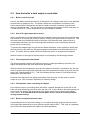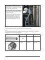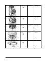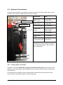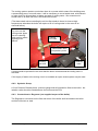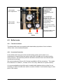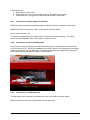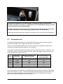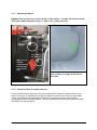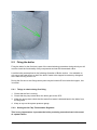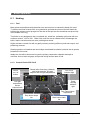
1
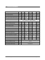
Attack Gasification Boiler Installation and Service Manual August 2011 Attack DP25, DP35, DP45, DP75, DP95 Profi Gasification Boilers The look of the DP Profi gasification boiler has changed as shown above. However the changes are almost totally to do with styling with the exception of a pressure gauge that now comes with the boiler, just under the control panel; and a flue gas thermostat. The working parts of the boiler are identical to the previous version. Therefore the pictures and diagrams in this manual are still relevant even when the older styling is shown. © Central Heating New Zealand 2 of 53 August 2011 Table of Contents 1 2 3 4 5 6 7 8 Technical Information ..................................................................................................... 4 How Gasification Boilers Work ....................................................................................... 5 2.1 Main Boiler Parts.................................................................................................... 6 2.2 How the boiler‟s heat output is controlled ............................................................... 7 System Design ............................................................................................................... 9 3.1 Recommended Design........................................................................................... 9 3.2 Boiler Temperature Maintenance Valve (Oventroppe Regumat) ...........................10 3.3 Insulated Flue System...........................................................................................12 3.4 Buffer tanks...........................................................................................................12 3.5 Control of Buffer Tank Systems ............................................................................13 3.6 Overheating protection ..........................................................................................14 Installation .....................................................................................................................17 4.1 Boiler and flue clearances .....................................................................................17 4.2 Poujoulat Flue .......................................................................................................17 4.3 Flue Height and Configuration...............................................................................20 4.4 Hydronic Connections ...........................................................................................24 4.5 Buffer tanks...........................................................................................................26 4.6 Electrical Connections...........................................................................................28 4.7 Combustion Air .....................................................................................................30 Commissioning ..............................................................................................................31 5.1 Before firing the boiler for the first time ..................................................................31 5.2 Firing the boiler .....................................................................................................33 Boiler Operation ............................................................................................................36 6.1 Heating .................................................................................................................36 6.2 Cleaning ...............................................................................................................41 Servicing and Maintenance ...........................................................................................46 7.1 Trouble shooting ...................................................................................................46 7.2 Common Issues ....................................................................................................47 7.3 Maintenance .........................................................................................................48 Appendix .......................................................................................................................51 8.1 Buffer Tank Technical Data ...................................................................................51 © Central Heating New Zealand 3 of 53 August 2011 1 Technical Information DP25 DP35 DP45 DP75 DP95 kW 10 - 25 14 - 35 18 - 45 30 - 75 40 - 95 Fuel chamber capacity litres 96 112 128 305 440 Fuel chamber door size mm 235x445 235x445 235x445 294x545 294x545 Depth of fuel chamber (front to back) mm 590 690 790 1100 Max. length of logs mm 550 650 750 1000 Heat output 1000 Recommended fuel Dry wood of 15-17 MJ/kg calorific value, water content min 12%, max 20%, 80 – 150mm diameter Chimney draught Pa 23 23 23 23 23 Maximum operating pressure bar 3 3 3 3 3 Weight kg 350 390 420 650 800 Volume of water in boiler litres 68 78 87 164 250 Flue outlet diameter (OD) mm 150 150 150 219 219 Boiler height mm 1080 1080 1080 1320 1535 Boiler width mm 580 580 580 750 766 Boiler depth mm 1050 1150 1265 1600 1680 Minimum size of buffer tank litres 500 800 1200 1800 2400 Thermal efficiency % 85 85 86 86 86 Flue gas temperature at full power ºC 230 225 220 262 245 Flue gas mass flowrate full power Kg/s 0.017 0.019 0.022 0.045 0.058 Maximum noise level dB 65 65 65 65 65 Boiler power – not including pump W 50 50 60 60 90 Electrical supply V/Hz 230 VAC 50Hz Operating temperature range ºC 65 - 95 Range of room temperature (Profi) ºC 10 - 27 Current rating of boiler relays V/A 1.5A 230V AC © Central Heating New Zealand 4 of 53 August 2011 2 How Gasification Boilers Work When wood is heated to 200ºC to 300ºC it releases pyrolysis gases that are combustible and can be burned like other combustible gases, hence the term gasification. When wood is heated for long enough, in an oxygen free environment, all the pyrolysis gases are driven off and all that is left is charcoal. To make this work in a boiler we partially combust the wood to produce the heat needed to drive off the pyrolysis gases, any charcoal that is left is also burnt in the partial combustion, also known as reduction zone, which ensures that all the energy in the wood is used to produce heat. This gas is composed approximately of 20% hydrogen 20% carbon monoxide 0% to 10% methane 50% to 60% Nitrogen, a non combustible gas from the air used for partial combustion The partial combustion and gasification zone is known as the primary combustion chamber and the secondary combustion chamber is where the pyrolysis gases are burnt. To get this working correctly the primary air supply has to be enough but no more than necessary for partial combustion. Gasification is really a controlled way of burning wood which is cleaner and more efficient than burning in conventional ways. To get the boiler running it is loaded with kindling and wood, the fire is lit, often using a blow torch, and it runs automatically until it runs out of fuel. It can be stoked with more fuel whilst it is going. © Central Heating New Zealand 5 of 53 August 2011 2.1 Main Boiler Parts The Attack DP Gasification boiler 1. Boiler body 2. Upper panel 3. Feeding door – to primary combustion chamber 4. Ash door 5. Exhaust induction fan 6. Flue 7. Fire concrete moulding - jet for secondary combustion 8. Fire concrete moulding – secondary combustion chamber 9. Boiler thermostat 10. Reset button © Central Heating New Zealand 11. 12. 13. 14. 15. 16. 17. 18. 19. 20. 21. 22. 23. 6 of 53 Flue gas thermostat (standard boilers only) Flow temperature thermostat On/off Switch Flow temperature display Thermostatic valve to control air damper (20) Boiler cooling coil Upper and lower cleaning covers Flow connection Return connection Air intake damper Pull rod for chimney flap Room thermostat (Profi version only) Flue gas sensor August 2011 2.2 How the boiler’s heat output is controlled 2.2.1 Boiler control of pump Once lit, the boiler controls the amount of heat given out, limiting it when there is low demand and the boiler is getting too hot. The boiler controls the pump directly to make sure the boilers temperature is maintained and that it is able to transfer heat away from the boiler when it is producing heat. The pump comes on at a boiler temperature of 65ºC and goes off if it falls below 60ºC. (These temperatures can be changed if needed.) 2.2.2 Use of flue gas temperature sensor When a buffer tank is used and has been fully heated the water returning from the buffer tank can exceed 65°C causing the pump to continue running even when the fuel is burnt out. This will cause heat to be transferred back to the boiler from the buffer tank, and will result in unnecessary heat loss from the connecting pipes and boiler; and unnecessary electrical power use to run the pump. To prevent this happening a flue gas sensor allows the boilers control system to detect that the fuel has burnt out when the flue gas temperature falls below a set level after the fuel is burnt. The boiler will then switch off the fan and pump until it is re-fuelled and restarted. When the boiler is burning fuel the heat output is controlled by the following methods: 2.2.3 Flow temperature thermostat The flow temperature setpoint will affect the amount of heat generated by the boiler, the higher the temperature the more heat will be generated. When the boiler flow temperature gets up to the setpoint the boiler‟s combustion fan will slow down to reduce heat output and eventually stop if the temperature keeps rising, and not start again until it has dropped by 5ºC. This is the boilers primary means of controlling the flow temperature from the boiler. However even without the fan going the draught of the chimney can still result in a heat output of up to 70% full output, depending on chimney design. 2.2.4 Thermostatic valve controlling air damper Even when the fan is not working there will still be a natural draught due to the flue so the boiler will keep producing heat even when the fan is off. If this results in the boiler getting too hot the main air damper flap at the back of the boiler will be closed using a thermostatic valve, below. It is essential that this thermostatic valve is set to the correct position during commissioning. 2.2.5 Boiler cooling thermostatic valve A secondary device to stop over-heating is a coil within the boiler body that can be cooled using cold water admitted by a valve when the boiler reaches 95ºC. This valve is a separate part to the boiler and needs to be ordered and fitted separately. © Central Heating New Zealand 7 of 53 August 2011 As this too uses a non-electrical thermostatic valve it stops the boiler being damaged by boiling dry even if there is a power cut. The cooling water supply used can be either mains water supply, or a header tank if the customer has a water pump which will also stop working if there is a power cut. A drain needs to be provided for the cooling water discharged if the thermostatic valve is operated. Thermostatic Air Damper Thermostatic valve for boiler cooling Thermostatic valve rotates lever to move chain up and down to control air damper Thermostatic valve controlling air damper The valve rotates a lever that is attached to the flap by a chain. The temperature the damper closes at needs to be set at commissioning. This provides overheating protection even if there is no power. View of the back of the boiler. Primary combustion air damper Chain from Thermostatic valve to air damper Secondary combustion air damper Air regulator flap All connections to the boiler should be made in copper, not plastic composite as shown in these pictures. © Central Heating New Zealand 8 of 53 August 2011 3 System Design 3.1 Recommended Design The following additional parts are recommended for a good quality installation and for good performance from the heating system. 1. 2. 3. 4. Boiler temperature maintenance valve, Regumat. Insulated flue – to reduce condensation and creosote build up Thermostatic valve for over-heating protection, Watts STS 20 or Danfoss equivalent Buffer tank to allow boiler optimum operating conditions and reduce hands-on attention to the boiler. Given that the boiler is controlled by electrical and mechanical thermostatic means, and has non electrical safety cooling, the boiler can be part of a sealed system with a maximum pressure operating of 3 bar. The Profi versions of the Attack boiler supplied by CHNZ are provided with a simple room temperature sensor that is set manually using a dial on the boiler. This enables the boiler to modulate it‟s heat output according to the room temperature. However this is not needed if a buffer tank is used and this input is now used instead for the flue gas temperature sensor. When using a buffer tank any central heating controls can be used when configured to use the buffer tank as a heat source. Or, looked at another way the boiler and buffer tank can be seen as being a single heat source which can deliver very small amounts of heat or very large amounts for short periods of time, giving rapid response. Any heating controller controls pump from buffer tank to supply hot water to heating and DHW Boiler Buffer tank © Central Heating New Zealand Heating, DHW etc 9 of 53 August 2011 Key parts of a log boiler system Insulated flue To drain Mains cold water Thermostatic valve (95ºC) Buffer Tank Cooling coil Boiler Removable cap for cleaning Thermostatic mixing valve (Regumat) 3.2 Boiler Temperature Maintenance Valve (Oventroppe Regumat) Solid fuel burners burn more efficiently and cleanly when the boiler return temperature is kept at least to 65ºC. This also prevents condensation corrosion in the heat exchanger. A primary means of achieving this is to have the circulation pump controlled from the boiler so that it doesn‟t run unless the boiler temperature is above 65ºC. The Attack gasification boiler uses this method, however when there is a large amount of return water from a buffer tank or heating system the boiler is continually cooled with cold water every time the pump goes on. To prevent this a boiler temperature maintenance thermostatic valve is used. The Oventroppe Regumat available as an extra item with the boiler. This is a mixing valve that keeps the return water to the boiler up to the temperature set on the thermostatic valve. The operation is shown below over. © Central Heating New Zealand 10 of 53 August 2011 Flow Boiler Whilst the boiler is warming up from cold all of the flow water is diverted directly back to the boiler. Return Once the flow temperature exceeds the thermostatic valve setting some of the flow is mixed with the return to maintain the return temperature at the set value. Boiler When the whole system is up to temperature and the return water is hot enough no water is diverted back to the boiler. Boiler Using a thermostatic valve also ensures that the flow entering the buffer tank is always at a higher temperature even when the return water from the buffer tank is cold. We recommend the Regumat is set at 6 to maintain the correct temperature. © Central Heating New Zealand 11 of 53 August 2011 3.3 Insulated Flue System The need to keep the boiler warm extends to the flue system where a cold flue leads to condensation which can combine with hydrocarbons in the flue to make creosote. An insulated flue keeps the gases warm as they go up the flue which also increases the natural draught. CHNZ supply the Therminox modular insulated flue system from Poujoulat. This has 32mm of rock wool insulation between the inner flue and outer case. (50mm for larger flues.) The 200mm system recommended for the boilers is certified for use in NZ according to AS/NZS 2918. 3.4 Buffer tanks Buffer tanks provide two main functions in a log boiler system: 1. One is to allow the boiler to keep burning at optimum efficiency independent of the variations in the load, leading to less fuel used and cleaner burning. 2. The other is to allow the boiler to be loaded and fired only once a day and all the heat stored in the buffer tank to be used throughout the remaining 24 hours. Both these functions require the buffer tanks to be sized in relation to the boiler‟s firebox volume which determines the amount of heat produced in one burn. In practice the boiler may be sized so that it will provide enough heat on most days in the winter but will need to be stoked more than once on cold days. If the users want to wake up to a warm house it is important that the buffer tank can store enough heat from the previous evening to heat up the house in the morning at the time of day when the heat load is at its highest. The amount of heat required per day depends on the insulation level of the house, the solar gain on that day and the occupants lifestyle, whether they like high temperatures and the amount of time they spend at home. In practice buffer tanks will usually still be warmer than ambient temperature and need further capacity to allow for a full burn of logs without over heating. For example the owner might want to fire up the boiler over night so there is sufficient heat in the morning. © Central Heating New Zealand 12 of 53 August 2011 Recommended buffer tank capacity: Boiler Minimum buffer volume Recommended DP25 500 litres 800 to 1600 litres DP35 800 litres 1600 to 2400 litres DP45 1200 litres 1600 to 2400 litres DP75 1800 litres 2400 to 4000 litres DP95 2400 litres 3000 to 5000 litres The volumes are best achieved with more than one buffer tank mounted in parallel. Note: Buffer tanks are not suitable for potable water and need protecting with corrosion inhibitor. Due to the volume of the buffer tank more corrosion inhibitor will be needed – large containers are available Take into account for expansion tank calculation. 3.4.1 Types of buffer tank 1. The AK which is a storage tank with multiple inlets and outlets. 2. The AS is a storage tank with multiple inlets and outlets and also a coil in the lower part of the cylinder for solar connection. CHNZ only stocks 800 litre tanks; 1000 litre and above only available on special order. 3.5 Control of Buffer Tank Systems 3.5.1 Control of buffer tank heating The heating of the buffer tank is controlled by the boilers control system as the temperature at the top of the buffer tank is the same as, or a bit less than, the boiler flow temperature. The boiler flow temperature is controlled by the boiler. As the boiler has to be loaded and lit manually to start, there is no point in having an electronic buffer tank controller which would start and stop the boiler, as this can‟t be done automatically. 3.5.2 Control of heating and DHW load The heat from the buffer tank allows for very good control as it is possible to take out very small amounts of heat or very large amounts, more than the boiler capacity, for short periods of time. For example if it takes a 20kW boiler an hour to heat up a buffer tank, if all that heat is taken out again in half an hour the heat output of the buffer tank for half an hour is 40kW. This is only true for half an hour, and then the only heat available will be from the boiler. © Central Heating New Zealand 13 of 53 August 2011 Another issue to be aware of is that the buffer tank will cool as heat is taken out and that may result in the operating temperature of the system being less than design operating temperature. Since underfloor runs at a lower temperature than radiators more heat can be extracted from a buffer tank before it drops below operating temperature. In reality heating systems tend to run at part load most of the time and so this is not a big issue, and that also means the boiler will usually be putting some heat into the heating load and some into the buffer tank. In general the user should try to keep the buffer tank hot and not let it get too cool. As the buffer tank acts as a buffer between the boiler and the heating and DHW systems any controller can be used. Including: Controller System Configuration Honeywell Smartfit Single heating zone and DHW Honeywell CM907 or CM927 (RF) One or more heating zones, S-plan or S-plan plus Aube stat with floor probe 1 Underfloor heating zone Watts RF or wired stat with floor probe 1 Underfloor heating zone Aube stat controlling actuators on underfloor manifold Multi zone underfloor Watts multi zone wired controller with actuators on underfloor manifold Multi zone underfloor Watts pipe stat and Honeywell timer Separately controlled DHW cylinder 3.6 Overheating protection Although the boiler should be protected against overheating by the air flap closing and other heat limiting strategies the boiler may still overheat and potentially boil the water leaving the boiler dry. In a sealed system the water can potentially reach 134°C before boiling if it is at 3 bar pressure. To prevent the boiler getting this hot a cooling coil is provided in the top of the boiler water jacket that allows the boiler to be cooled by passing cold water through the coil. The flow of water through this coil is controlled by a thermostatic valve set to open at 95ºC. The water supply to this valve is usually mains cold water. If there is a risk that this cooling water is not always available, such as where there is a pumped water system which stops in a power cut, means of ensuring a water supply needs to be found or use of an open vent system may be preferable. A header tank can be used with a minimum 2m head will still provide a good cooling capacity if the tank holds 200 litre. A 25mm pipe to the thermostatic valve is required to ensure good flow rate at low pressure which should be in copper within 2m of the boiler. A 200 litre expansion vessel can be used instead of a tank which is fed by mains water through a non return valve. This saves having to install a header tank with filling valve and © Central Heating New Zealand 14 of 53 August 2011 overflow. Take care to avoid a situation where the expansion vessel will get air trapped inside instead of water. A thermostatic valve of the type used for boiler thermal protection. The temperature probe (top) is fitted to the boiler body and the valve left to the cooling coil inlet. Watts STS 20‟s are specified but are interchangeable with the Danfoss valve shown left. Header tank for emergency cooling water 200L minimum header tank Cold water supply 25mm copper pipe to ensure good flow rate At least 2m above the top of the boiler Thermostatic valve probe in boiler Thermostatic valve Boiler © Central Heating New Zealand 15 of 53 Copper pipe to drain, also needs to be greater than 16mm to ensure good flow rate. August 2011 Expansion vessel for emergency cooling water AAV Cold water supply Check valve 200L expansion vessel precharge 1bar 25mm copper pipe to ensure good flow rate Thermostatic valve probe in boiler Thermostatic valve © Central Heating New Zealand Boiler 16 of 53 Copper pipe to drain, also needs to be greater than 16mm to ensure good flow rate. August 2011 4 Installation The boiler is ideally suited to be installed in a dedicated plant room either inside or outside the house. This will usually provide adequate space for clearances which are needed for service access as much as safety, and room for buffer tank(s) and other ancillary equipment. Ideally there should be easy access to a store of dry fuel wood to make it easy to re-fuel in wet weather or when it is dark. 4.1 Boiler and flue clearances The DP35 is different from other DP and FD boilers as it has been tested for minimum clearances. The 200mm flue has also been tested and is certified for use in NZ to 25mm clearance which applies to all installations with that flue. Clearance rules apply to heat sensitive walls. Timber frame with gib is a heat sensitive wall. 4.2 Poujoulat Flue The 200mm Poujoulat flue has been tested according to AS/NZS2918 and is certified for use in New Zealand to a clearance of 25mm, however the brackets supplied with this flue system will give a 50mm clearance. This applies to all solid fuel boiler installations. The flue system is a modular system and care has to be taken not to place any joints between sections inside a ceiling, roof or wall penetration. 4.2.1 DP35 Installation clearances and certification The DP35 boiler has been tested in New Zealand, to AS/NZS 2918: 2001, to provide certified minimum clearances from the boiler to the nearest heat sensitive surfaces. A copy of the test report is available on request if you need to show building control. (CRL reference 1041088) The boiler has an insulated case around most of the boiler as it is designed to transfer heat via a pumped hot water system rather than by radiating heat. The minimum clearances given are for heat sensitive walls, these include anything on timber frame such as gib. Clearances can be reduced by using heat shielding in accordance with AS/NZS 2918 – Solid Fuel Burning Appliances - Installation. A heat shield would be something like a metal sheet barrier with a gap behind it of 12mm or 25mm with clearance for ventilation around the edges of the heat shield. The clearances in the DP35 diagram below can be further reduced by using the clearance factors in the table below. © Central Heating New Zealand 17 of 53 August 2011 DP35 Minimum clearances for heat sensitive walls and for servicing 230mm 400mm 50mm Access needed this side to air dampers and ash clearing doors at rear of boiler 1860mm 500mm 500mm 1580mm Leave sufficient space in front to open the doors for cleaning and refuelling. 1 meter recommended 4.2.2 1000mm DP25, DP45, DP75, DP95 Installation clearances The other DP boilers supplied by Attack have not been tested and must use default clearance distances or heat shielding if a heat sensitive walls and ceilings are too close. Default clearances from NZS 2918 – Solid Fuel Burning Appliances – Installation are generally 1.2m from a heat sensitive wall and 1.5m from a heat sensitive ceiling, but can be reduced if not a heat sensitive wall or heat shielding is used. Timber frame walls with gib lining are heat sensitive, concrete or concrete block walls are not. If in doubt check with building control to find out what they are happy with before finalizing a design. © Central Heating New Zealand 18 of 53 August 2011 4.2.3 Compliance with minimum installation clearances Method A Build the wall with non heat sensitive materials such as concrete block, tilt-slab or metal. Method B Use heat shielding: A heat shield must be a single layer of continuous material such as sheet steel or masonry. When heat shielding is used the default minimum to a heat sensitive wall can be reduced according to the level of heat shielding by multiplying 1.2m by the clearance factor Minimum clearance distances for walls and ceilings when using heat shielding according to AS/NZS 2918 Minimum air gap (mm) Clearance factor Minimum distance to wall (m) Minimum distance to ceiling (m) Single layer 12 0.4 0.48 0.6 Single layer 25 0.3 0.36 0.45 12 + 12 0.2 0.24 0.3 Two spaced layers The heat shielding must have air gaps at top and bottom to allow ventilation to cool the heat shielding. The area of the vents must be at least half the cross section behind the shield. For example if it is 12mm off the wall the area of the vent must be 6mm all the way across. If the distance from the appliance to the ceiling above it is less than 1.5m heat shielding must be installed and the clearance reduced by multiplying 1.5m by the clearance factors in the table above. We highly recommend a space of at least 500mm be left on the right hand side of the boiler as looked at from the front to allow access for adjusting thermostatic valve, cleaning heat exchanger and flue. 4.2.4 Floor protection Installation on concrete floors doesn‟t require any additional protection. If installing on a timber floor, although the heat from the boiler will not cause damage, we recommend a metal plate is used under and around the boiler to prevent the risk of fire from any spilt ashes during cleaning or re-fuelling. This plate should be under the boiler and extend outwards to 500mm from the boiler or to the wall if closer. If installing on a timber floor we recommend consulting a structural engineer to confirm that the floor is able to take the weight of the boiler. © Central Heating New Zealand 19 of 53 August 2011 4.3 Flue Height and Configuration 4.3.1 Flue Draught The boiler must have 23 Pascal‟s flue draft when burning at maximum power. This is checked by inserting a hole in the vertical part of the flue and using a digital manometer or flue gas analyser with draught measurement. The DP35 and 45 require a minimum of: 200mm inside diameter insulated flue at a height of 5.8m. However, local conditions prevail and if more flue is required then it needs to be added until 23 Pascal‟s is obtained. 4.3.2 Flue diameter and height Central Heating New Zealand recommends a 200mm circular flue to be fitted to the Attack DP25, DP35 and DP45 boilers. This is bigger than the 150mm OD flue outlet on the boilers because a 200mm flue is preferred to produce more draught at lower flue heights. The minimum flue heights for 150mm diameter flues are generally 7m or more which is too high for a single storey house which most installations are in NZ. As a guide only, the recommended flue height for a 200mm ID insulated flue is 5.8m above the boiler outlet, but more height maybe required if local conditions mean not enough draught is obtained with that height. An adaptor needs to be ordered for the flue to connect with the 150mm outlet on the rear of the boiler. There must always be sufficient draft in the flue and flue gas must be vented to the atmosphere in all possible operation conditions. For the optimum operation of the boiler the flue must be the correct height for the cross sectional area used. The draught is influenced by the section of flue, height and roughness of the internal wall, and by local wind conditions. No other appliance can be attached to the same flue. If using other flues, the flue diameter must not be smaller than the outlet on the boiler. © Central Heating New Zealand 20 of 53 August 2011 The flue should also be designed to allow easy access for cleaning the best way to do this is to have a Tee connection at the back of the boiler like the picture right. In this case the flue has a removable cap at the bottom allowing cleaning from below and there is a condensate drain although that is not used in this picture. Horizontal sections and bends should be avoided if at all possible. If a section of horizontal flue needs to be used then it should be kept as short as possible and should be easily accessed for cleaning. The flue can be made up using the combinations of the following parts. Indicates parts used for the standard configuration shown in this manual. This doesn‟t include parts for ceiling and roof penetration. Poujoulat Therminox parts Description Part no: 130mm Part no: 200mm 950mm straight 21 130 005 21 200 005 21 130 021 21 200 021 45º bend © Central Heating New Zealand 21 of 53 August 2011 90º Tee 21 130 50 21 200 50 150mm to 200mm Adaptor 21 150 314 Drain plug 21 130 090 21 200 090 21 130 87 21 200 87 21 130 75 21 200 75 Rain cap Wall bracket © Central Heating New Zealand 22 of 53 August 2011 © Central Heating New Zealand Extending arms for wall bracket 200 – 400mm 21 130 135 21 180 135 Ceiling plate 21 130 035 21 200 035 23 of 53 August 2011 4.4 Hydronic Connections Flow and return pipework near the boiler, between the boiler and thermostatic valve, and to the buffer tank if close coupled should be made in copper. Cooling coil outlet Cooling coil inlet Flow Connection Size Flow: DP25,35 DP45,75,95 1 ½ “ male BSP 2” male BSP Return: DP25,35 DP45,75,95 1 ½ “ male BSP 2” male BSP Fill and drain point ½ “ male BSP Cooling water supply Site dependent. Mains supply or tank needed. Cooling water inlet ½ “ male BSP Cooling water outlet ½ “ male BSP Cooling water drain Site specific The drain size for the cooling coil water outlet depends largely on the flow rate of the cooling water. Return Fill and drain 4.4.1 Cooling water connections Pipework to the boiler should be in copper to within 2m of the boiler to prevent any heat damage to the supply pipes. (Not plastic/aluminium composite pipe as shown in the pictures in this manual.) Any isolating valve between the water supply and the thermostatic valve should be fixed open to prevent accidental isolation of the cooling water. © Central Heating New Zealand 24 of 53 August 2011 The cooling system needs to work when there is no power which means if the building uses a pressurising pump, from well water, it will be necessary to use a header tank, with ballcock or other device to ensure there is always a supply of cooling water. We recommend a header tank of at least 200 litres if this method is chosen. (The thermostatic valve controlling the air inlet flap needs to be set to close at high temperatures otherwise the boiler will require a lot of cooling water in the event of an electrical failure.) Try not to run the cooling water pipes over the cleaning hatch as this makes cleaning more difficult. Cooling coil outlet Thermostatic valve temperature probe Cooling coil inlet Cleaning hatch A drain should be provided in the event that the boiler overheats and the cooling valve is activated. If the supply of water to the cooling circuit is unreliable an open vented system may be used. 4.4.2 Hydronic Group A 3 bar Pressure Release Valve, pressure gauge and AAV should be fitted to the boiler. No isolation valve should be fitted between the boiler and the PRV. 4.4.3 Connections to ‘Regumat’ (not supplied as part of the boiler) The Regumat is connected on the flow and return of the boiler and lies between the boiler and the buffer tank or load. © Central Heating New Zealand 25 of 53 August 2011 The Oventroppe Regumat boiler temperature maintenance pump station. Thermostatic valve adjustment The temperature gauges are also handles for turning the isolating valves incorporated in the Regumat unit. Thermostatic valve sensor There is also a check, non-return valve, in the flow side. The thermostatic valve should be set at 6. Return Flow Boiler 4.5 Buffer tanks 4.5.1 Thermal insulation The Attack buffer tanks are supplied with detachable polyurethane foam insulation, 100mm thick, with a leatherette jacket. 4.5.2 Corrosion Protection As the buffer tank forms part of the central heating system and is steel, it is a requirement to correctly dose the system water with a suitable anti corrosive inhibitor such as Fernox. This corrosion protection should be checked on an annual basis and maintained accordingly. We recommend using Fernox CH-3 which is available in 25 litre containers. This needs to be dosed at 1% solution. (10 litres of CH-3 for every 1000 litres of system volume) It is recommended that the buffer tank is installed with isolation valves so that it is not necessary to drain the buffer tank with its corrosion inhibitor if work needs doing on other parts of the system. © Central Heating New Zealand 26 of 53 August 2011 4.5.3 Connections to boiler and load Place the buffer tank on the floor, as close to your boiler as possible. Put on the insulation. Connect the heating circuit to inlets and outlets depending on the temperature distribution in the tank. Mount an air vent valve at the highest point of the tank and insulate all the pipe connections Ensure the heating system has the correct expansion allowed for either by open vent or by expansion vessel and pressure relief valve not exceeding 3 bar. NB: Failure to observe expansion correctly may result in damage and/or personal harm. To maximise the performance of the buffer tank it should be plumbed in accordance with the diagram below. Heat outlet to heating, must be as high as possible to use all available heat. Flow from boiler high to avoid too much mixing, but doesn‟t have to be at the top as the hot water will rise. Water stratifies with hot water rising to the top Bimetallic temperature gauges to show temperatures at different levels in the tank. Return to boiler must be as low as possible to use all of tank. 4.5.4 Return from heating or DHW. Buffer tank temperature gauges It is also useful to put temperature gauges at different heights on the tank so the user can tell how much heat is stored. Only having gauges at the top and bottom doesn‟t show the whole picture due to stratification. A gauge at the top of the tank only shows the temperature at the © Central Heating New Zealand 27 of 53 August 2011 very top whereas one a third of the way down tells you that all the water above that gauge is at least at the temperature shown on the gauge. In the picture below the third gauge down shows that the tank at that height is hot, the bottom gauge that at the bottom it is cold. So the user knows the tank is hot for at least two thirds of the way down. Bimetallic gauges are used which require temperature pockets or wells to be fitted in the tank in the appropriate temperature gauge ports. The tank needs to be positioned so the temperature gauges can be seen. When the boiler is running the temperature gauges on the Regumat show: 1. Flow temperature is the same as the top of the tank. 2. Return temperature gauge shows the set temperature of the Regumat , usually around 60ºC until the bottom of the tank exceeds that and then the return gauge will show the temperature at the bottom of the buffer tank. This information is only valid when the circulating pump is running and pumping water through the Regumat, and through the buffer tank. 4.5.5 Buffer tank sizes See appendix for size and heights of connections. Technical Data Type Units AK500* AK800 AK1000* AS500* AS800* AS1000* Volume litres 500 800 1000 500 800 1000 1.9 2.9 3 Max operating temp ºC 100 Max operating pressure bar 3 2 Area of exchanger m Insulation (polyurethane) mm Diameter with insulation mm 800 990 990 800 990 990 Diameter of tank mm 600 790 790 600 790 790 Height mm 1970 1750 2050 1970 1750 2050 Tilt height mm 2080 1880 2170 2080 1880 2170 n/a n/a n/a 100 *Only available on special order 4.5.6 Warranty The warranty on the buffer tanks is invalid if insufficient corrosion inhibitor is used or if the expansion vessels are too small. 4.6 Electrical Connections The boiler has a control system and a fan and runs the primary circulation pump. This requires 230 VAC 50Hz power. © Central Heating New Zealand 28 of 53 August 2011 Connections are: 1. Mains power to the boiler. 2. Power from the boiler to the circulation pump, controlled by the boiler. 3. Combustion fan – plugged into connection at the back of the boiler. 4.6.1 Connection of mains power to the boiler Electrical power should be provided through an isolation switch located near to the boiler. Maximum Power Consumption: 50W + pump power, typically 100W Size of power breaker: 4A The boiler is supplied with a European type of plug that will need changing. The mains power is connected behind the control panel; see photo below. 4.6.2 Connection to the circulating pump As a primary means of keeping the boiler warm the pump is controlled from the boiler and only runs above 65ºC. Ideally the installation will use the pump on the Regumat as a primary means of circulation through the boiler. The pump connections are made to the connection block behind the control panel as shown in photo below. 4.6.3 Connection to combustion fan The fan plugs into a connector provided at the rear of the boiler as shown below. Make sure the fan can move freely before fixing to the boiler. © Central Heating New Zealand 29 of 53 August 2011 No electrical connections or electrical parts, including the pump, should not be situated under the flue as there is a significant risk of condensation leaking out of the flue at some point in the system lifetime. All cables should be routed and secured to avoid contact with hot parts of the boiler. The back of the boiler is not protected by insulation and is the hottest part. All electrical connections should be made in accordance with relevant electrical regulations. 4.7 Combustion Air The Attack DP gasification boiler is an open fanned flue boiler which therefore requires permanent ventilation to be supplied to the room it is situated in. There is no New Zealand guidance for the area of permanent ventilation needed so we recommend using the UK govt guidance on this subject. It should be noted that the dimensions given are for the total open area, or „free area‟, of a vent which means a vent with a mesh or louvres needs to be bigger to take account of the area blocked by the mesh or louvres. Boiler Total area of vent (mm2) Minimum Dimension of square vent (mm) DP25 11,300 106 Minimum Diameter of round vent (mm) 120 DP35 16,800 130 146 DP45 22,300 149 169 DP75 38,800 197 222 DP95 49,800 223 252 Even under optimum conditions it is inevitable that some smoke will escape from the boiler when the boiler door is open. Therefore the boiler should be placed in an area where that will not be a problem and apart from providing ventilation for combustion air it is good practice to provide ventilation to clear any smoke. © Central Heating New Zealand 30 of 53 August 2011 This can be achieved by having ventilation at both high and low levels in the room where the boiler is situated. Ideally the boiler should be installed in a dedicated plant room either inside or outside the house, with adequate ventilation for combustion and smoke clearance provided. 5 Commissioning 5.1 Before firing the boiler for the first time 5.1.1 Fill and Purge System Eliminate air from the system as much as possible – once the boiler gets going there will be a lot of heat to move and it won‟t stop in a hurry if you find you have airlocks! It‟s a good idea to run the pump directly if you can to circulate the water round the system and help purge it of air. It is recommended that the system should be pressurised to 1 bar when cold. When first run it there is likely to be air in the system which will lead to pressure increases when the system starts to heat up. Continue to purge the system so that no water is lost due to over pressure. Set the Regumat to 6. 5.1.2 Test thermostatic valve Test the operation of the boiler cooling thermostatic valve and drain by pressing the red button on the valve. Make sure the water is drained properly when full flow is established. © Central Heating New Zealand 31 of 53 August 2011 5.1.3 Adjusting Dampers Ignore the instructions on the back of the boiler: loosen the lock screws and push both dampers fully in, and lock in that position. Primary air damper Secondary air damper Main air cutoff flap controlled by thermostatic valve at the tiop 5.1.4 The ceramic ash tray should be pushed back so there is no gap at the back of the boiler. Check position of ceramic ash tray Check that the ceramic ash tray in the lower combustion chamber is pushed firmly to the back of the boiler so that there is no gap and that the 2 halves are touching in the middle. These can dislodge during transport and allow flue gasses to exit the boiler without exchanging heat into the water jacket. This can cause excessive flue gas temperature and fan failure, see picture above. © Central Heating New Zealand 32 of 53 August 2011 5.2 Firing the boiler Firing the boiler for the first time is part of the commissioning procedure during which you will need to check the functionality of key components and set the thermostatic valve. Load the boiler as described in the following Operation of Boiler section. It is advisable to only use a half load at first so that if the boiler needs to be stopped to make any changes it won‟t take too long to burn out. During the first one or two firings some paint may be burned off from inside the hopper, this is normal. 5.2.1 Things to check during first firing 1. Check that the fan is running 2. Check that the pump starts when the boiler gets to the 65ºC. 3. When the pump starts check that the warm flow water is diverted back to the boiler from the Regumat. 4. Keep an eye on the system pressure gauge 5.2.2 Setting the Air Flap Thermostatic Regulator This is very important as it prevents the boiler producing excessive heat in the event of a power failure. © Central Heating New Zealand 33 of 53 August 2011 The principle of the air flap at the rear of the boiler is that it should be fully closed at 85 to 90ºC. This needs to be confirmed during commissioning by running the boiler up to 90ºC to check the flap is closed at that temperature. Adjustment of the thermostatic valve is achieved first by lengthening and shortening the chain between the thermostatic valve lever and the air flap, and then by turning the top of the valve so it is closed when the boiler reaches 90ºC or a lower value if chosen. The thermostatic valve with lever in correct position is shown below The lever is more or less horizontal when the boiler is not in use. © Central Heating New Zealand 34 of 53 Air flap in approximate boiler off position. Chain below flap not attached to anything. August 2011 It is important to check that the flap closes correctly and if necessary put a weight on the flap is there is any doubt that it will always close. Once the valve has been set to the correct position tie the chain to the eye bolt at the back of the boiler so that the chain is always the correct length and remove the top of the valve to prevent anyone from changing the position of the valve. 5.2.3 Setting the flue gas temperature cut off To prevent the pump running on after the boiler has run out of fuel it is necessary to set a flue gas temperature below which the control system will know the combustion is finished. If this is set too high the boiler may go off before the fuel is burnt out. If it is set too low the pump will continue running long after the boiler has burnt out. A temperature that works for most people is 100°C. This is set by turning the small knob at the lower left corner of the control panel with the house and thermometer symbol below it. (This knob can also be used for setting a room temperature sensor, hence the symbols.) To adjust the temperature turn the knob and the display will instantly change and show the setting. When adjustment is finished the display will revert back to flow temperature after a short period. 5.2.4 Setting other Service Parameters There are numerous other parameters controlling such things as the temperature the pump comes on etc which can be accessed by holding down the OK button for 3 seconds. Changing service parameters 1. 2. 3. 4. 5. 6. Hold down OK button for 3 seconds Browse parameters using +/- buttons Press OK to select a parameter to change Alter value with +/- buttons Confirm by pressing OK To exit use +/- to find END and then press OK A full list of parameters and their function can be found in the Appendix to the manual that comes with the boiler. This is an A5 document separate to the manual. © Central Heating New Zealand 35 of 53 August 2011 6 Boiler Operation 6.1 Heating 6.1.1 Fuel Many perceived problems with the boiler have turned out to be caused by damp fire wood. To ensure the wood is below 20% a log should be split and the moisture content tested by sticking the moisture meter prongs into the side of the split into the wood that was previously in the middle of the log. This boiler is only designed to burn untreated, dry, wood fuel, preferably split wood with low moisture content, 12% to 20%. Other fuels, such as coal or treated wood, will damage the boiler, lead to corrosion and are more polluting than wood. Higher moisture content fuel will not gasify correctly reducing efficiency and heat output, and producing creosote. Small proportions of sawdust and wood chips are allowed but should not block the air spaces between the fuel wood. Ideally the fuel will be almost as long as the primary combustion chamber and split to minimise, but not block air gaps, and provide a high surface area of fuel. 6.1.2 Control Panel of DP Profi Power on / off button Shows boiler flow temp, (default), also boiler setpoint, flue gas setpoint and flue gas temperature Out of fuel indicator light Pump running indicator light Flue gas temperature sensor setpoint knob Flow Temperature Adjustment Stop button stops fan © Central Heating New Zealand Start button starts fan 36 of 53 August 2011 Indication Out of fuel indicator light flashes and pump and fan stop during start up phase. If the flue gas temperature doesn‟t reach the set temperature after the set start up time this light flashes and the boiler stops. Reducing the flue gas set temperature can start the boiler again if it is burning fuel. Out of fuel indicator light on solid shows flue temperature is below the set level and that boiler will stop after a further set time. (Default is 30 mins) The boiler will stop after a set time unless the fire is stoked and flue gas temperature increases. Information shown on display Example Boiler temp (default) 77 > Boiler setpoint C 80 > Flue gas set point 100c > Actual flue gas temp 180° > End – press OK to exit menu End To see the other temperatures, apart from boiler temperature, press OK and use and buttons. To exit go to „End‟ and press OK. © Central Heating New Zealand 37 of 53 August 2011 6.1.3 Starting up the boiler If the orange light is on indicating „out of fuel‟ switch the boiler off then on again using the power switch. Then check that the fan is running. It is important not to block the slot at the bottom of the primary combustion chamber as this is where the gas flows through to the second combustion chamber below. Leave a gap of 20 to 40mm for air to flow through the slot at the bottom of the primary combustion chamber. The fire should be constructed with a fire starter such as newspaper or firelighters, under kindling and then the main wood fuel. Shown here with only the back half of the chamber loaded. This is typical Kiwi firewood which isn‟t the best shape for loading the maximum volume of wood and minimising air gaps. Air gaps are needed for the gasification process but large air gaps mean less fuel is loaded at any one time. © Central Heating New Zealand 38 of 53 August 2011 Before lighting the fuel flap knob at the front of the boiler should be pulled out which opens a port at the back of the combustion chamber to let the smoke go straight up the flue. Once the fire is going this should be closed again. If the fuel flap is left open most of the heat will go up the chimney instead of to the heating system. This can also damage the combustion fan. The upper cleaning hatch has been removed to show what is inside the back of the boiler. Normally this is secured closed. The fire can be lit with matches, or a blow torch for faster ignition. This fire is going well after a 5 second blast from a blow torch into the middle of the fire. When the fire starts up there will be condensation in the flue which will evaporate once the flue warms up. This happens much quicker with an insulated flue. This condensation may leak out of the flue initially if there are any unsealed parts. Remember to close the fuel flap once the fire is going © Central Heating New Zealand 39 of 53 August 2011 Once the fire is going well the kindling and paper burns down leaving room to put more fuel in. 6.1.4 Opening the door during burning If you want to look in the primary combustion chamber, or put more fuel in, first open the fuel flap and leave for 15 seconds before opening the door a crack and leave for another 10 seconds and finally open the door very slowly. Rushing this process will lead to considerable amounts of smoke coming out of the door. Remember to close the flap again afterwards by pushing in the knob. The boiler should not be run for prolonged periods at output below 50% as this will increase the build up of creosote and soot. This will happen if fuel is loaded when the system is already hot and there is no load, the air flap will close and output will be reduced. 6.1.5 Day to day operation A key question is how often to run the boiler, and how much fuel to put in? In reality this will be different for each user depending on the heat loss of the house and the amount of DHW used,(if heated by the boiler), time at home and room temperatures set on thermostats. More of any of those factors means more fuel needs to be burnt. One of the biggest factors, heat loss, is out of the users control as it is largely dependent on the outside temperature, and the insulation levels of the house which don‟t often change. The decision on whether to reload the boiler and produce more heat depends on: What is the likely heat load in the immediate future? Depends a lot on the weather and if the heating is going to be on or not. How much heat is already stored in the buffer tank? If the user thinks there is enough heat in the buffer tank to meet the load in the future then no more heat is needed. The user will have to get to know their system and how much heat they need to meet immediate demand. More buffer tank capacity allows for more heat to be stored and for a bigger margin of error. The coldest part of the day is just before and after dawn and this is generally when central heating systems use most heat. Therefore it is a good idea if you know it is going to be cold © Central Heating New Zealand 40 of 53 August 2011 in the morning to burn some fuel in the evening or last thing at night to charge up the buffer tank(s). It is not necessary to fill the boiler with wood if only a small load is anticipated, such as in the summer if there is only a hot water load it may make more sense to burn half loads. How do you know how much heat is in the buffer tanks? If you are using a Regumat it is possible to see the temperature at the top of the buffer tank which is the same as the flow temperature as the boiler and what is shown on the Regumat temperature gauge. The return temperature gauge on the Regumat will show the Regumat‟s set temperature which is usually around 60ºC. Once the bottom of the buffer tank exceeds this temperature the return gauge will also increase and show the temperature of the water coming from the bottom of the buffer tank to the boiler. If you have temperature gauges on the buffer tanks they will give a better picture of how much heat is in the tank. Radiator systems and DHW heating usually require operating temperatures of 70ºC to 80ºC and so we want to charge the tank to temperatures in excess of that, particularly in colder weather. Underfloor systems run at lower temperatures but it is still good to charge the tank to a high temperature as that way it holds more heat and has more potential energy for the heating system. It is standard practice to charge the tank up to 90ºC at the top in order to hold as much heat as possible. 6.2 Cleaning The boiler needs to be cleaned regularly when in constant use as ash/soot build up on the heat exchanger surfaces will decrease the efficiency of the boiler. Frequency of cleaning depends on the amount of wood burnt, but generally during the heating season once a week is good practice. Ash isn‟t necessarily a bad thing when it sits on the ceramic liners in the primary and secondary combustion chambers as it acts as insulation which is also what the ceramics are doing. However when it starts to take up space it needs to be removed, and when it coats any metal surfaces it reduces the heat exchanger efficiency. Tar on the walls of the primary combustion chamber, log hopper, is normal in gasification boilers. The flue gas temperature when the boiler is in normal operation should be around 200°C to 250°C. If the temperature is higher it is an indication that the heat exchanger needs cleaning. Or possibly the fuel flap has been left open, or the lower ceramic is not pushed to the back of the boiler. © Central Heating New Zealand 41 of 53 August 2011 Ashes should be put in a fire proof container outside the building. Scraper and brush provided with the boiler for cleaning. Remove ash from upper and lower ceramics if excessive amounts have built up. Upper chamber shown right with ash starting to build up. Although it doesn‟t look like much a bucket of ash was removed from this boiler after the picture was taken The cleaned out chamber with more volume available for fuel. © Central Heating New Zealand 42 of 53 August 2011 The ash in these pictures is not a problem on the ceramic parts but the ash stuck on the boiler walls, left and right, decreases heat transfer to the boiler from the flue gases. The ash on the ceramics can be removed using a dust pan and brush. Dispose of ash in a fire proof container outside the building. Scrape the ashes off the side of the heat exchanger and generally clear the channel between the ceramic and the heat exchanger wall. Using the scraper pull the ashes to the front and clear the channel. © Central Heating New Zealand 43 of 53 August 2011 Remove the cleaning hatch at the rear of the boiler, below to show inside of heat exchanger, right Use scraper to remove ash stuck to flat surfaces of the heat exchanger. Use brush to clean ash from the fins and other places not reached by the scraper. Don‟t push the brush too hard into any spaces it doesn‟t want to go or it may get stuck. Replace hatch when finished. © Central Heating New Zealand 44 of 53 August 2011 Most of the ash will have fallen down to the bottom of the heat exchanger and this can be removed by taking off the rear bottom cleaning hatch. Use a brush to clear out as much ash as possible. Replace hatch afterwards. © Central Heating New Zealand 45 of 53 August 2011 7 Servicing and Maintenance 7.1 Trouble shooting If boiler exceeds 110ºC a safety thermostat locks out the boiler. This is reset by turning the boiler thermostat to the left as far as possible. In cold weather the boiler needs to be fuelled more often and run at a high temperature to ensure maximum temperature output. To get maximum heat out of the boiler, make sure fuel is dry, fill the fuel chamber and turn up the thermostat to maximum. Problem Solution House is not warming enough Check that your central heating controller is calling for heat, may show a flame symbol when it is. If not turn up thermostat and/or TRVs on radiators, or mixing valve on underfloor manifold. Boiler not getting to temperature on thermostat Check that there is enough fuel. Check that fuel isn‟t wet Check the air regulation flap isn‟t closing at too low a temperature Check all air intakes are free from obstruction Fan may need cleaning. Check that the boiler doesn‟t need cleaning. If it does need cleaning the heat exchanger works less efficiently and more heat goes up the chimney instead of into the heating system. Fan not turning or If not turning first try resetting the boiler by turning the thermostat dial round to the left as far as it will go. Check the motor condenser is not faulty Check the motor isn‟t faulty Fan is noisy The fan accumulates dust and soot over time so it needs to be cleaned to prevent excessive build up that makes it less effective. E1 displayed on boiler: A temperature sensor is faulty. Call service agent © Central Heating New Zealand 46 of 53 August 2011 7.2 Common Issues Most performance problems encountered with the boiler are caused by the following factors Wet wood: Wood fuel must be less than 20% Moisture which can be checked with a moisture meter. Wood that is too wet is the most common cause of poorly performing boilers. Wet wood: Wood fuel must be less than 20% Moisture which can be checked with a moisture meter. Wood that is too wet is the most common cause of poorly performing boilers. Wet wood: Wood fuel must be less than 20% Moisture which can be checked with a moisture meter. Wood that is too wet is the most common cause of poorly performing boilers. Flue draught: The boiler must have 23 Pascal‟s flue draft when burning at maximum power. This is checked by inserting a hole in the vertical part of the flue and using a digital manometer. The DP35 and 45 require a minimum of: 200mm inside diameter insulated flue at a height of 5.8m. However, local conditions prevail and if more flue is required then it needs to be added until 23 Pascal‟s is obtained. Ceramic Ash Tray: Check that the ceramic ash tray in the lower combustion chamber is pushed firmly to the back of the boiler so that there is no gap and that the 2 halves are touching in the middle. These can dislodge during transport and allow flue gasses to exit the boiler without exchanging heat into the water jacket. This can cause excessive flue gas temperature and fan failure. Dampers: Despite what the decals and install manual indicate, loosen the lock screws and move the primary and secondary air damper adjusters to the fully „IN‟ position. In the fully „in‟ position, the boiler has the correct amount of primary and secondary air. Flue gas temperature: Check that the flue gases at the flue outlet are between 200-250 degrees Celsius at maximum power. If flue gasses are hotter than this it indicates a dirty heat exchanger or some other problem. Return temperature maintenance: Position 6 on the Oventrop regumat maintains a return temperature of 65 degrees Celsius to the boiler before sending heat out to the buffer tank. A return temperature to the boiler of above 60 degrees is required for optimum fuel combustion. Each number on the thermohead adjusts the temperature by 5 degrees. When opening the door to refuel, pull the lever out and wait for 15 seconds, then crack the door handle open and leave for a further 10 seconds before opening the door slowly. Opening the door quickly causes a lot of smoke to come out. Often when these items have been checked and rectified, the boiler and flue are left in their previous sooted up state. Please ensure that after rectification of faults, that the boiler and flue are fully cleaned to enable optimum performance. © Central Heating New Zealand 47 of 53 August 2011 7.3 Maintenance Task Frequency Clean fan unit to remove all soot. Six monthly Check door seals and adjust door if necessary Yearly Check that thermostatic thermal protection valve is working Yearly Clean flue using a suitable brush or hire professional chimney cleaner Yearly Check the Regumat is working correctly Yearly Change ceramic moulding If existing is worn out or damaged 7.3.1 Changing the packing cord of the door Dismantle the old packing cord with a screwdriver and clean the rabbet where it was placed. Take the new packing cord and put its beginning on the horizontal parts of the rabbet. With your hand or light knock of the hammer press it into the rabbet on the circumference of the door. 7.3.2 Adjustment of hinges After some time the packing cord in the door gets deformed. To repack the door, it is necessary to change the position of the door. The position is changed by tightening the hinges of the door. Feeding door and bottom door are joined to the body with two hinges which are attached to the door with a long pin. If we want to change the adjustment of hinges, it is necessary to remove the pin and screw the hinge by turning it. Fit the door on and insert the pin into the hinge. 7.3.3 Changing the Nozzle The nozzle is the ceramic piece with a slot between the primary and secondary combustion chambers. This is sealed by a glass fibre packing cord. To remove, dig the packing cord out with a screwdriver and pull out the nozzle. Clean out any residues where the nozzle is seated. Put the new nozzle in place with the shorter part at the back pushed up against the back of the boiler. The gap between the sides of the nozzle and the boiler must be the same on each side. Lightly knock the packing cord into the gap until it is flush with the top of the nozzle. © Central Heating New Zealand 48 of 53 August 2011 7.3.4 Changing the lower heat proof moulding Remove the damaged moulding and clear and residues from the boiler surface. Put the rear part, 1, into the lower chamber by putting it in sideways and then turning it. Push it up against the steel plate at the rear. Insert one side piece and then the other by turning it to fit through the door and then rotating to the correct position. (2 & 3) Push the two side parts together and push them to the back to join up with the first piece of the moulding. © Central Heating New Zealand 49 of 53 August 2011 7.3.5 Wiring Diagram © Central Heating New Zealand 50 of 53 August 2011 8 Appendix 8.1 Buffer Tank Technical Data The buffer tanks come in three sizes: 500 litre, 800 litre, 1000 litre Only the 800 litre tank is stocked by Central Heating New Zealand but the others can be ordered on special order. There are two types in each volume: AK: with direct connections to heating and load. AS: with the same direct connections but with an added heat exchange coil in the bottom of the tank. Technical Data Type Units AK500 AK800 AK1000 AS500 AS800 AS1000 Volume litres 500 800 1000 500 800 1000 1.9 2.9 3 Max operating temp ºC 100 Max operating pressure bar 3 Area of exchanger m2 Insulation (polyurethane) mm Diameter with insulation mm 800 990 990 800 990 990 Diameter of tank mm 600 790 790 600 790 790 Height mm 1970 1750 2050 1970 1750 2050 Tilt height mm 2080 1880 2170 2080 1880 2170 © Central Heating New Zealand n/a n/a n/a 100 51 of 53 August 2011 AK buffer tanks © Central Heating New Zealand 52 of 53 Volume Height (mm) 500 800 1000 A 280 280 330 B 605 630 745 C 1635 1409 1690 D 600 790 790 E 800 990 990 F 1970 1750 2050 G 1180 957 1050 H 1245 1100 1300 Weight (kg) 67 115 137 1 Return water to boiler 2 Return from heating 3 Flow from boiler / DHW 4 Flow to heating / DHW 5 G½ for temperature sensors etc August 2011 AS buffer tanks with coil heat exchanger © Central Heating New Zealand 53 of 53 Volume Height (mm) 500 800 1000 A 280 280 330 B 605 630 745 C 1635 1409 1690 D 600 790 790 E 800 990 990 F 1970 1750 2050 G 1180 957 1050 H 1245 1100 1300 Weight (kg) 67 115 137 1 Return water to boiler 2 Return from heating / DHW 3 Flow from boiler 4 Flow to heating / DHW 5 G½ for temperature sensors etc 6 From solar collector 7 To solar collector August 2011