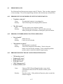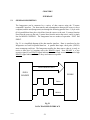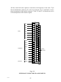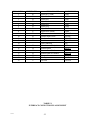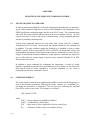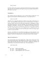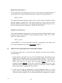
1
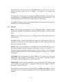
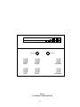
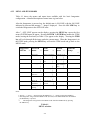
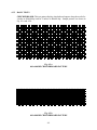
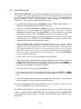
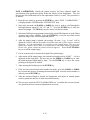
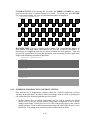
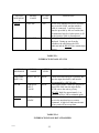
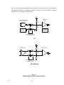
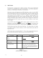
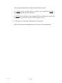
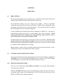
CHAPTER 4
OPERATION
4.1
PRECAUTIONS
Do not turn off the main power or pull the power cord from the wall outlet without first
turning off the POWER switch located on the back of the unit.
The Imagesetter employs only low voltage power supplies. However, hazardous
voltages are present in the motor driver and in the AC input wiring. Reasonable safety
precautions should be used to avoid electrical shock. Turn the unit off before replacing
the media supply roll or servicing any component.
Circuits installed on the thermal print head are composed of CMOS ICs. Care must be
taken during operation and service to avoid damage from static electricity. When
replacing the print head, conductive mats and grounding straps should be used to
prevent damage due to electrostatic discharges (ESD).
The print head may become dirty even after short periods of operation. Clean the print
head every time a new roll of media is installed. Turn the power off and clean the print
head with the alcohol-saturated pads supplied with the unit. Allow time for the alcohol
to evaporate before turning the power on again.
Never attempt to operate the unit without media moving across the print head. Such a
condition may cause severe damage and void the warranty.
4.2
CONTROL PANEL KEYPAD FUNCTIONS
To access control panel selections, the Imagesetter must be taken off line by toggling the
ON LINE key once. The green ONLINE light will go off, and the "OFF LINE" message
will be displayed. The layout of the control panel is shown in Fig. 4.1.
4.2.1 FRONT PANEL INDICATORS
There are two LED indicators (ON LINE and STATUS) on the panel. Both indicators
are bi-color (green and red).
When the ON LINE indicator is lit green, the Imagesetter is in On Line state and ready to
accept data; when it goes off, the Imagesetter is in OFF LINE state and can go to the
MENU or ITEM mode to change parameters.
4-1
If the Imagesetter detects any error, the STATUS indicator will be lit red. An error
message will also be shown on the VF display. See Section 4.4 for detailed error
messages.
The Imagesetter will not accept any data when the STATUS indicator is lit red with error
message displayed. A flashing red color STATUS indicator means WARNING! The
warning message will be seen on the VF display (such as "Low Media").
The STATUS indicator will be lit green when the Imagesetter performs certain functions,
such as media cut and media form feed.
4.2.2
KEYPAD
MENU: This key allows the operator to cycle through the MENU selections during
Imagesetter OFF LINE: SYSTEM menu, JOB menu, IMAGE menu or print the System
Setup.
ITEM: This key allows the operator to cycle through all the ITEMs listed under one of
the basic menus.
ON LINE: This key switches the Imagesetter between ON LINE and OFF LINE. The
Imagesetter will be ready to receive data only during ON LINE, with the ON LINE
indicator on the panel lit green.
ENTER: This key allows operator to go from MENU to ITEM selection and also to save
the selected parameter into the Imagesetter's "permanent" memory. Two asterisks "**"
will appear next to the parameter to indicate that it is now the default. As a "permanent"
default, the selection will remain valid even if the Imagesetter is switched OFF, or RESET
is performed.
CUT/PARM+: This key initiates the plotter MEDIA CUT function only when the
"Imager OFF LINE" message is on the display. It is also used as a parameter scroll up
key (PARM+) when the Imagesetter is in the ITEM mode.
FEED/PARM-: This key will move the media 4" long only when the OFF LINE message
is on the display. It is also used as a parameter scroll-down key (PARM-) when the
Imagesetter is in the ITEM mode.
When parameters are displayed for a selected ITEM, the PARM+ and PARM- keys allow
the operator to cycle up or down through the parameter selections (options) that are
available.
4-2
I MA GER ON L I NE
ON LINE
STATUS
MENU
ON LINE
CUT/PARM+
ITEM
ENTER
FEED/PARM-
Fig 4.1
CONTROL PANEL KEYPAD
4-3
4.2.3
MENU AND ITEM MODES
Table 4.1 shows the menus and menu items available with the basic Imagesetter
configuration. A detailed description of menu items is given below.
After the Imagesetter is powered up, the default state is ON LINE, with the ON LINE
indicator lit green and the message "... Imager" displayed. Press the ON LINE key to
switch the Imagesetter to the OFF LINE state.
After "... OFF LINE" appears on the display, pressing the MENU key causes the first
menu (SYSTEM menu) to appear. Pressing the ITEM or ENTER key enables the ITEM
mode, causing the first item (see Table 4.1) to appear on the display. Pressing the ITEM
key will cycle through all the items under the current menu. When the Imagesetter is in
the ITEM mode, pressing the MENU key will exit the ITEM mode and go back to the
MENU mode.
Imagesetter
Off Line ®
SYSTEM
menu
®
JOB
menu
Scan Line
Imager Resolution
¯
System Test
®
Media Type
¯
Cut
Hysteresis Control
¯
Fan Control
¯
¯
Imager Speed
¯
Show Transport
Parm
¯
¯
Negative Image
¯
Detection
Luminance Level
Zig-Zag Toggling
¯
¯
Reset All
Footage
¯
Mirror Image
Low Media
Parameters
Total Image
Print the
Setup
Contrast Level
¯
Automatic Media
¯
IMAGE
menu ®
¯
Closed-loop
¯
Control
¯
¯
Notes:
1. Arrows "® " and "¬ " mean pressing the MENU key; "¯ " means pressing the ITEM key.
2. The Imagesetter will go from the MENU mode (first row) to the ITEM mode after the ITEM or
the ENTER key is pressed.
3.
The Imagesetter will go back to the MENU mode from the ITEM mode by pressing
the MENU key.
Table 4.1
MENU selection
4-4
¬
4.2.4
PARAMETER SELECTION
ITEMs for each of the three menus (SYSTEM, JOB, and IMAGE) and their
PARAMETER selections are listed in Table 4.2, 4.3 and 4.4, respectively.
In the ITEM mode, the item along with its default parameter value is on the display.
Pressing the PARM+ or PARM- key will scroll up or down through all the available
parameter values for that specific item.
Any available parameter value can be selected and permanently saved by pressing the
ENTER key when it is displayed. Two asterisks "**" will appear on the display next to
the selected parameter value, indicating its acceptance.
4.3
TESTING
The Imagesetter features built-in plotting/printing tests to verify that the unit is operating
normally, and to provide a guideline for choosing the appropriate contrast setting. The
self-test functions should be used after initial installation and in case of trouble-shooting.
4.3.1
TEST PROCEDURE
·
Make sure that the media is loaded.
·
Turn on the power switch.
·
Press the ON LINE key to switch the Imagesetter to OFF LINE. This status will
be seen on the Front Panel VF Display.
·
Select the SYSTEM menu and the System Test item.
·
The PARM+ or PARM- key may be used to select the desired test:
·
- Checkerboard
- ASCII Print
- Platen Accuracy
- Plot Calibration
- Open-loop Check
- Nib Test
- Contrast Test
- Dot Size Test
Press ENTER to initiate the test.
4-5
ITEM
Scan Line
System Test
Media Type
Fan Control
Low Media Detection
Luminance Level
Reset All Parameters
PARAMETER
- Either Full or Partial;
Fixed for each model as:
18Ó- 900 bytes per line @400dpi
24Ó- 1184 bytes per line @400dpi
36Ó- 1776 bytes per line @400dpi
42Ó- 2080 bytes per line @400dpi
- Checkerboard
- ASCII Print
- Platen Accuracy ...
- Plot Calibration ...
- Open-loop Check ...
- Nib Test
- Contrast Test ...
- Dot Size Test ...
- Paper
- Film
- Automatic On/Off
- Always On
- Turn Off Now
- No
- Yes
- Check Media Length
25% to 100%
(25% increment)
- No
- Yes
Total Image Footage
DEFINITION
Raster line length
- Raster test
- Print test
- Platen accuracy test
- Fine adjustment of platen accuracy
- Coarse adjustment of platen
accuracy (Note 1)
- Print head Nib Test
- For a range of contrast
- For a range of contrast
Imagesetter will select correct energy
level for different media
Mode and action of fan control (Note
2)
(Note 3)
Display brightness
Reset System/Job/Image item
parameters to factory preset values
Display the accumulative image
footage of use on film and paper
Notes
1.
Usually the platen accuracy has been adjusted within the specification at the production facility
before the delivery of the Imagesetter. The user may run the Plot Calibration test for fine
adjustment if there is a need. The Open-loop Check test is seldom needed; however, it is provided
as a diagnosis and coarse adjustment tool in case that the platen accuracy can not be corrected by
utilizing only the Plot Calibration test. In such case, it is recommended that the user also contact
the technical support.
2.
In the Automatic mode, the fan will be turned on whenever the printing process starts, and off after
the printing is completed and the system cools down. In the Always On mode, the fan is on all
the time and can be turned off when "Turn Off Now" is selected.
3.
When "Yes" on Low Media Detection is selected, the STATUS LED will be flashing red after the
Imagesetter detects only about 20 feet of media left in the roll; warning message will also be
displayed during on line. The "Check Media Length" choice is available only when the "Yes"
choice is selected. Entering "Check Media Length" will give a rough estimate of media length
available in the roll.
Table 4.2
ITEMs of SYSTEM Menu
4-6
ITEM
PARAMETER
DEFINITION
Imager Resolution
- H: 400 dpi V: 400 dpi
- H: 400 dpi V: 800 dpi
H (horizontal):
along the print head
V (vertical):
the direction of media movement.
Automatic Media Cut
- No
- Yes
Cut the media after receiving EOT
Hysteresis Control
- No
- Yes
Print head control with consideration of
data in the neighboring dots
Mirror Image
- No
- Yes
Mirror image print of input data
Negative Image
- No
- Yes
Negative image print of input data
Zig-Zag Toggling
- No
- After EOT
- After EOT/FF
Every print shifts 1 bit right after EOT or
FF (Note 1)
Closed-loop Control
- No
- Yes
Turn off or on the closed-loop control of
platen accuracy adjustment
Notes
1.
Every image will shift 1 bit right. The image will restart from the original beginning after 32
images at 400 dpi. The last four bytes of the input data shall be blank to ensure that no data will
be lost during Zig-Zag mode.
Table 4.3
ITEMs of JOB menu
4-7
ITEM
PARAMETER
DEFINITION
Contrast Level
-35% to +20%
(5% increment)
Adjust image contrast level
Imager Speed
0.1 to 0.5 ips
(Note 1)
Show Transport Parm
- No
- Yes
Display transport parameters for
debugging usage in Platen
Accuracy Test and after FF or
EOT during on-line imaging
Notes
1.
Ranges of printing speed for papers
· hysteresis off: 0.125 to 0.5 ips.
· hysteresis on: 0.1 to 0.4 ips.
For films, the printing speed is fixed at 0.25 ips and 0.2 ips for hysteresis control mode
off and on, respectively.
Table 4.4
ITEMs of IMAGE menu
4-8
4.3.2
BASIC TESTS
CHECKERBOARD: This test pattern displays checkerboard squares along the media for
4 inches at 400x400 dpi and for 2 inches at 400x800 dpi. Sample patterns are shown in
Fig. 4.2.a and 4.2.b.
Fig. 4.2.a
400 x 400 DPI CHECKERBOARD PATTERN
Fig. 4.2.b
400 x 800 DPI CHECKERBOARD PATTERN
4-9
ASCII PRINT: This test pattern prints 40 lines of 96 ASCII characters across the media.
The resolution of the plot is indicated on the left side of the printout. Sample patterns
are shown in Fig. 4.3.a and 4.3.b.
***
***
***
***
***
***
***
***
***
***
***
***
***
***
***
***
***
***
***
***
***
400 dpi ***
400 dpi ***
400 dpi ***
400 dpi ***
400 dpi ***
400 dpi ***
400 dpi ***
400 dpi ***
400 dpi ***
400 dpi ***
400 dpi ***
400 dpi ***
400 dpi ***
400 dpi ***
400 dpi ***
400 dpi ***
400 dpi ***
400 dpi ***
400 dpi ***
400 dpi ***
400 dpi ***
!Ó#$%Õ( )*+,-./0123456789:;< + >?@ABCDEFGHIJKLMNOPQRTSUVWXYZ[ \
!Ó#$%Õ( )*+,-./0123456789:;< + >?@ABCDEFGHIJKLMNOPQRTSUVWXYZ[ \
!Ó#$%Õ( )*+,-./0123456789:;< + >?@ABCDEFGHIJKLMNOPQRTSUVWXYZ[ \
!Ó#$%Õ( )*+,-./0123456789:;< + >?@ABCDEFGHIJKLMNOPQRTSUVWXYZ[ \
!Ó#$%Õ( )*+,-./0123456789:;< + >?@ABCDEFGHIJKLMNOPQRTSUVWXYZ[ \
!Ó#$%Õ( )*+,-./0123456789:;< + >?@ABCDEFGHIJKLMNOPQRTSUVWXYZ[ \
!Ó#$%Õ( )*+,-./0123456789:;< + >?@ABCDEFGHIJKLMNOPQRTSUVWXYZ[ \
!Ó#$%Õ( )*+,-./0123456789:;< + >?@ABCDEFGHIJKLMNOPQRTSUVWXYZ[ \
!Ó#$%Õ( )*+,-./0123456789:;< + >?@ABCDEFGHIJKLMNOPQRTSUVWXYZ[ \
!Ó#$%Õ( )*+,-./0123456789:;< + >?@ABCDEFGHIJKLMNOPQRTSUVWXYZ[ \
!Ó#$%Õ( )*+,-./0123456789:;< + >?@ABCDEFGHIJKLMNOPQRTSUVWXYZ[ \
!Ó#$%Õ( )*+,-./0123456789:;< + >?@ABCDEFGHIJKLMNOPQRTSUVWXYZ[ \
!Ó#$%Õ( )*+,-./0123456789:;< + >?@ABCDEFGHIJKLMNOPQRTSUVWXYZ[ \
!Ó#$%Õ( )*+,-./0123456789:;< + >?@ABCDEFGHIJKLMNOPQRTSUVWXYZ[ \
!Ó#$%Õ( )*+,-./0123456789:;< + >?@ABCDEFGHIJKLMNOPQRTSUVWXYZ[ \
!Ó#$%Õ( )*+,-./0123456789:;< + >?@ABCDEFGHIJKLMNOPQRTSUVWXYZ[ \
!Ó#$%Õ( )*+,-./0123456789:;< + >?@ABCDEFGHIJKLMNOPQRTSUVWXYZ[ \
!Ó#$%Õ( )*+,-./0123456789:;< + >?@ABCDEFGHIJKLMNOPQRTSUVWXYZ[ \
!Ó#$%Õ( )*+,-./0123456789:;< + >?@ABCDEFGHIJKLMNOPQRTSUVWXYZ[ \
!Ó#$%Õ( )*+,-./0123456789:;< + >?@ABCDEFGHIJKLMNOPQRTSUVWXYZ[ \
!Ó#$%Õ( )*+,-./0123456789:;< + >?@ABCDEFGHIJKLMNOPQRTSUVWXYZ[ \
FIG. 4.3.a
400 x 400 DPI ASCII PRINT PATTERN
***
***
***
***
***
***
***
***
***
***
***
***
***
***
***
***
***
***
***
***
***
400X800 DPI ***
400X800 DPI ***
400X800 DPI ***
400X800 DPI ***
400X800 DPI ***
400X800 DPI ***
400X800 DPI ***
400X800 DPI ***
400X800 DPI ***
400X800 DPI ***
400X800 DPI ***
400X800 DPI ***
400X800 DPI ***
400X800 DPI ***
400X800 DPI ***
400X800 DPI ***
400X800 DPI ***
400X800 DPI ***
400X800 DPI ***
400X800 DPI ***
400X800 DPI ***
!Ó#$%Õ( )*+,-./0123456789:;< + >?@ABCDEFGHIJKLMNOPQRTSUVWXYZ[ \
!Ó#$%Õ( )*+,-./0123456789:;< + >?@ABCDEFGHIJKLMNOPQRTSUVWXYZ[ \
!Ó#$%Õ( )*+,-./0123456789:;< + >?@ABCDEFGHIJKLMNOPQRTSUVWXYZ[ \
!Ó#$%Õ( )*+,-./0123456789:;< + >?@ABCDEFGHIJKLMNOPQRTSUVWXYZ[ \
!Ó#$%Õ( )*+,-./0123456789:;< + >?@ABCDEFGHIJKLMNOPQRTSUVWXYZ[ \
!Ó#$%Õ( )*+,-./0123456789:;< + >?@ABCDEFGHIJKLMNOPQRTSUVWXYZ[ \
!Ó#$%Õ( )*+,-./0123456789:;< + >?@ABCDEFGHIJKLMNOPQRTSUVWXYZ[ \
!Ó#$%Õ( )*+,-./0123456789:;< + >?@ABCDEFGHIJKLMNOPQRTSUVWXYZ[ \
!Ó#$%Õ( )*+,-./0123456789:;< + >?@ABCDEFGHIJKLMNOPQRTSUVWXYZ[ \
!Ó#$%Õ( )*+,-./0123456789:;< + >?@ABCDEFGHIJKLMNOPQRTSUVWXYZ[ \
!Ó#$%Õ( )*+,-./0123456789:;< + >?@ABCDEFGHIJKLMNOPQRTSUVWXYZ[ \
!Ó#$%Õ( )*+,-./0123456789:;< + >?@ABCDEFGHIJKLMNOPQRTSUVWXYZ[ \
!Ó#$%Õ( )*+,-./0123456789:;< + >?@ABCDEFGHIJKLMNOPQRTSUVWXYZ[ \
!Ó#$%Õ( )*+,-./0123456789:;< + >?@ABCDEFGHIJKLMNOPQRTSUVWXYZ[ \
!Ó#$%Õ( )*+,-./0123456789:;< + >?@ABCDEFGHIJKLMNOPQRTSUVWXYZ[ \
!Ó#$%Õ( )*+,-./0123456789:;< + >?@ABCDEFGHIJKLMNOPQRTSUVWXYZ[ \
!Ó#$%Õ( )*+,-./0123456789:;< + >?@ABCDEFGHIJKLMNOPQRTSUVWXYZ[ \
!Ó#$%Õ( )*+,-./0123456789:;< + >?@ABCDEFGHIJKLMNOPQRTSUVWXYZ[ \
!Ó#$%Õ( )*+,-./0123456789:;< + >?@ABCDEFGHIJKLMNOPQRTSUVWXYZ[ \
!Ó#$%Õ( )*+,-./0123456789:;< + >?@ABCDEFGHIJKLMNOPQRTSUVWXYZ[ \
!Ó#$%Õ( )*+,-./0123456789:;< + >?@ABCDEFGHIJKLMNOPQRTSUVWXYZ[ \
FIG. 4.3.b
400 x 800 DPI ASCII PRINT PATTERN
4-10
PLATEN ACCURACY: This test checks the stepping accuracy of the Imagesetter and
prints the nominal distance lines with inch annotations. A sample pattern is shown in
Fig. 4.4. Selections of different lengths ranging from one to eight feet and of different
patterns (normal grid or dark/filled interior) are available. The printed image may be
measured with an accurate scale to determine the platen accuracy. In case that the platen
accuracy adjustment is needed, the Plot Calibration or the Open-loop Check test may be
used (please refer to Section 4.3.3 Advanced Tests).
1
2
3
4
5
Fig. 4.4
PLATEN ACCURACY TEST PATTERN
4-11
NIB TEST: This test checks whether any failed nib of the print head exists. In addition
to the leading and tail mark lines, a vertical line of a half inch at 400x400dpi (one quarter
inch @ 400x800dpi) is plotted for every 8th nib; and at the end of each line, the next
adjacent nib continues the plot. This pattern repeats until all the nibs have completed the
plotting. Sample patterns are shown in Fig. 4.5.a and 4.5.b.
FIG. 4.5.a
400 x 400 DPI NIB TEST PATTERN
4-12
FIG. 4.5.b
400 x 800 DPI NIB TEST PATTERN
4-13
4.3.3
ADVANCED TESTS
OPEN-LOOP CHECK: This test is seldom needed by the user; however, it is provided
as a diagnosis and coarse adjustment tool in case that the platen accuracy can not be
corrected by only utilizing the Plot Calibration test. In such case, it is recommended that
the user contact the factory technical support before performing the OPEN-LOOP
CHECK test. The procedure is listed below for reference:
1. Enter this test mode by pressing the ENTER key when ÒOPEN-LOOP CHECK...Ó is
displayed under SYSTEM menu, SYSTEM TEST item.
2. Once in the test mode, the PARM+ or PARM- key may be used to scroll through the
Ònumber of slotsÓ choices among 640, 1280 and 1920. Note that 32 slots is
approximately one inch long. Press the ENTER key to select the desired test length
(for example, 640 slots ~20Ó). The ITEM key may be used to exit this test mode.
3. Selection of different image patterns (normal grid or dark/filled interior as in the Platen
Accuracy test) is also available. Press the ENTER key to run the test which would
output an image of the selected length and pattern.
4. After the output image is printed, the message ÒW=xxxx L=yy S=zzzzÓ will be
displayed (W and L indicate the number of window slots and of lines used for internal
diagnosis. S is the total number of scan lines of the printed image. The displayed W
value should be equal to the number of test slots selected by the user. The user may
ignore these numbers unless there is an abnormity in the platen accuracy adjustment.
In such case, please contact the factory technical support.) . Press the CUT/PARM+
key to cut off the output image.
5. Use an accurate scale to measure the length of the printed image.
6. After cutting off the output image, the nominal test length (such as 20.000Ó when # of
TestSlots=640 was selected) is first displayed. The user may use the PARM+ or
PARM- key to enter the actual measured length digit by digit. Use the ENTER key to
move the cursor pointing to the digit to be entered.
7. After entering the last digit, press the ENTER key.
8. If the user has entered an incorrect number carelessly, press the PARM+ or PARMkey to restart the process of entering the measured length; else, press the ENTER
key.
9. After the measured length is entered, the Imagesetter will adjust its internal platen
accuracy parameter and save it in the nonvolatile memory.
10. After performing the OPEN-LOOP CHECK test just once, the user may go to the
PLOT CALIBRATION test for fine adjustments.
The OPEN-LOOP CHECK is to be performed on only one type of media (either paper
or film). After the OPEN-LOOP CHECK the user should run PLOT CALIBRATION
on both media types (paper and film). DO NOT perform OPEN-LOOP CHECK for the
other media.
4-14
PLOT CALIBRATION: Usually the platen accuracy has been adjusted within the
specification at the production facility before the delivery of the Imagesetter. The user
may run the Plot Calibration test for fine adjustment if there is a need. The procedure is
as follows:
1. Enter this test mode by pressing the ENTER key when ÒPLOT CALIBRATION...Ó
is displayed under SYSTEM menu, SYSTEM TEST item.
2. Once in the test mode, the PARM+ or PARM- key may be used to scroll through the
test length choices among 36Ó, 48Ó, 60Ó and 72Ó. Press the ENTER key to select the
desired test length. The ITEM key may be used to exit this test mode.
3. Selection of different image patterns (normal grid or dark/filled interior as in the Platen
Accuracy test) is also available. Press the ENTER key to run the test which would
output an image of the selected length and pattern.
4. After the output image is printed, the message ÒW=xxxx L=yy S=zzzzÓ will be
displayed (W and L indicate the number of window slots and of lines used for internal
diagnosis. S is the total number of scan lines of the printed image. The user may
ignore these numbers unless there is an abnormity in the platen accuracy adjustment.
In such case, please contact the factory technical support.) . Press the CUT/PARM+
key to cut off the output image.
5. Use an accurate scale to measure the length of the printed image.
6. After cutting off the output image, the nominal test length (such as 36.000Ó, ...) is first
displayed on the front panel. The user may use the PARM+ or PARM- key to enter
the actual measured length digit by digit. Use the ENTER key to move the cursor
pointing to the digit to be entered.
7. After entering the last digit, press the ENTER key.
8. If the user has entered an incorrect number carelessly, press the PARM+ or PARMkey to restart the process of entering the measured length. After the correct number is
entered, press the ENTER key.
9. After the measured length is entered, the Imagesetter will adjust its internal platen
accuracy parameter and save it in the nonvolatile memory.
10. The user may repeat the PLOT CALIBRATION test to confirm the corrected result,
or to perform one more round of adjustment if necessary.
4-15
CONTRAST TEST: After entering this test mode, the PARM+ or PARM- key can be
used to select the range of contrast settings to be tested. To run the test, press ENTER.
For each contrast setting, two rows of checkerboard squares are displayed.
***
En ergy Level Test: Contrast from -10% to 0%
= = Contrast : -10% = =
= = Contrast : -5% = =
= = Contrast : -0% = =
DOT SIZE TEST: This test is similar to the Contrast Test, except that the image is of
mesh pattern, with each square representing a 2x2, 4x4, 6x6, or 8x8 dot (selectable). A
microscope or a magnifying lens may be used to examine the mesh patterns. This test
may provide a guideline to selecting the appropriate contrast setting for those application
images with demanding resolution requirement.
***
Dot Si ze Test: Size : Contrast from -3 5% to -25%
= = Contrast : -35% = =
= = Contrast : -30% = =
= = Contrast : -25% = =
4.3.4
GUIDELINE FOR SELECTING CONTRAST SETTING
Note that the use of inappropriate contrast setting for a specific media may void the
warranty on the print head. In order to achieve best image result as well as to prolong the
life of print head, the following guideline may be referred:
·
In the Contrast Test, an optical densitometer may be used to measure the optical
density (o.d.) of the plot at each contrast setting, and a comparison of o.d. at all the
settings can be made. Usually the curve of o.d. has a steep rising slope as the contrast
setting increases. Then it reaches the saturation point and either slides down or stays
almost flat. The setting at the saturation point would be the best choice.
4-16
4.4
ERROR MESSAGES
The following Error Messages may appear on the VF Display. There are three categories
of error messages. The error messages along with their cause and remedy are listed below.
4.4.1
4.4.2
4.4.3
ERRORS DUE TO INAPPROPRIATE SYSTEM CONFIGURATION
·
"No plotter connector"
Cause:
The print head connector is not plugged in.
Remedy:
Turn off the Imagesetter and plug in the connector.
·
"The lid is open!"
Cause:
The top section is not completely latched.
Remedy:
Close and latch the top section. Then reset the system by
Either pressing the reset button or turning the system off and on.
ERRORS OCCURRED DURING PLOTTING OPERATION
·
"Out of media!"
Cause:
Media runs out.
Remedy:
Load a new roll of media.
·
"Thermohead overheat!"
Cause:
The print head is overheated.
Remedy:
Turn off the Imagesetter immediately. Wait for the print
head to cool down before restarting. If the overheating problem
persists, please consult the technical support group.
ERRORS FROM ELECTRONIC SUBSYSTEMS INTERFACING
·
·
·
·
·
·
"TE Interface error!"
"Unknown TE error"
"TEIF Comm error!"
"TEIF Recv error!"
"TEIF Timeout error!"
"Unknown TEIF error!"
Cause:
Remedy:
Unknown TEIF (Thermal Engine Interface) error or bad
communication between the TE controller and the system
processor.
Reset the system. If the problem still persists, please consult the
technical support.
4-17
CHAPTER 5
INTERFACE
5.1
GENERAL DESCRIPTION
The Imagesetter can be connected to a variety of data sources using the "Versatec
compatible" interface. The data transfer and communication between the source (a host
computer) and the unit (Imagesetter) are through the following parallel lines: 1) byte-wide
(8-bit) parallel data lines plus a clock line from the source to the unit, 2) remote function
lines from the source to the unit, 3) status lines from the unit to the source, and 4) a single
line for MODE CONTROL. The Imagesetter has two modes of operation: PLOT and
PRINT.
Fig. 5.1 is a simplified diagram of the data transfer interface. Data is transferred to the
Imagesetter over an 8-bit parallel data bus. A parallel data input clock pulse (PICLK)
must accompany each byte. The Imagesetter notifies the data source when it is ready to
receive a data byte by asserting active the READY signal. Note READY is a low
assertive signal: a low READY signal indicates the unit is ready to receive data, and a high
READY signal indicates the unit is busy and cannot accept data.
BYTE-PARALLEL DATA
DATA
SOURCE
GS 6XX
PICLK
READY-
Fig 5.1
DATA TRANSFER INTERFACE
04/05/99
5-1
All data, control and status signals are connected to the Imagesetter via the male 37-pin
D-series subminiature connector (J1) at the rear of the unit. Fig. 5.2 and Table 5.1 show
the pin assignments of the interface connector. Table 5.2.a thru 5.2.d describes the active
levels and operations of the interface signals.
J1
DATA
CONTROL
STATUS
IN01
1
IN02
2
IN03
3
IN04
4
IN05
5
IN06
6
IN07
7
IN08
8
CLEAR-
9
PICLK
10
READY-
11
PRINT
12
N.C.
13
SPP-
14
RESET-
15
RFFED-
16
REOTR-
17
RLTER-
18
NOPAP
19
20
21
22
23
24
25
26
27
28
29
30
31
32
ONLIN(STATUS)
33
34
35
36
37
Fig. 5.2
INTERFACE CONNECTOR PIN ASSIGNMENTS
04/05/99
5-2
SIGNAL PIN
1
2
3
4
5
6
7
8
9
10
11
12
13
14
15
16
17
18
19
32
RETURN PIN
20
21
22
23
24
25
26
27
28
29
30
31
33
34
35
36
37
37
37
SIGNAL NAME
Input Bit 1 (LSB)
Input Bit 2
Input Bit 3
Input Bit 4
Input Bit 5
Input Bit 6
Input Bit 7
Input Bit 8 (MSB)
Clear
Parallel Input Clock
Ready
Print
Not Connected
Simultaneous Plot/print
Remote Reset
Remote Form Feed
Remote End of Transmit
Remote Line
No Paper
On-Line
MNEMONIC
IN01
IN02
IN03
IN04
IN05
IN06
IN07
IN08
CLEAR
PICLK
READY
PRINT
NC
SPP
RESET
RFFED
REOTR
RLTER
NOPAP
ONLIN
TABLE 5.1
INTERFACE CONNECTOR PIN ASSIGNMENT
04/05/99
5-3
SIGNAL
SIGNAL
MNEMONIC
NAME
PRINT
PRINT
ACTIVE
LEVEL
HIGH
OPERATION
This line selects either print or
plot operation.
High: PRINT; Low: PLOT
TABLE 5.2.a
INTERFACE SIGNALS: MODE CONTROL
SIGNAL
MNEMONIC
CLEAR
SIGNAL
NAME
REMOTE
CLEAR
ACTIVE
LEVEL
LOW
RESET
REMOTE
RESET
REMOTE
LINE
TERMINATE
LOW
REMOTE
FORM FEED
or
LOW
RLTER
RFFED
or
REOTR
LOW
REMOTE
END OF
TRANSMIT
OPERATION
This command clears the input buffer
when READY is low. READY
remains high until the input buffer has
been cleared.
This command resets the unit and
reinitiates all logic of the unit.
This command terminates the buffer
currently being loaded, causes all
previously loaded buffers to be output
in sequence, then outputs the buffer
just terminated at last. This command
is ignored by the unit if received
immediately after a full scan has been
automatically terminated.
This command terminates the buffer
currently being loaded, causes all
previously loaded buffers to be output
in sequence, then outputs the buffer
just terminated at last. After all data
is written on the media, it is advanced
approximately 4 inches.
* Remote functions and data should never be transmitted concurrently, else data
may be lost; all remote functions are low going pulses, 300 ns minimum.
TABLE 5.2.b
INTERFACE SIGNALS: REMOTE FUNCTIONS *
04/05/99
5-4
SIGNAL
MNEMONI
C
ONLIN
SIGNAL
NAME
ACTIVE
LEVEL
ON-LINE
LOW
NOPAP
NO PAPER
HIGH
OPERATION
A low level indicates the unit is powered
on, set to ON-LINE, and the interface
cable is connected. A pull-up resistor
must be provided by the user on this line
to maintain a high level when power is off
or the interface cable is disconnected.
A high level indicates the media supply is
depleted. During an out-of-media
condition, the unit flashes the LED
indicator and the READY line remains high
(busy).
TABLE 5.2.c
INTERFACE SIGNALS: STATUS
SIGNAL
MNEMONI
C
IN01-IN08
(BITS 1-8)
SIGNAL
NAME
ACTIVE
LEVEL
INPUT DATA
HIGH
PICLK
PARALLEL
INPUT
CLOCK
HIGH
READY
UNIT
READY
LOW
OPERATION
These lines enter one byte of parallel data
into the input data buffer, and must be
accompanied by a PICLK pulse.
This signal strobes a data byte present on
lines IN01-IN08 into the input buffer.
PCLK causes the unit to go busy
(READY high) for approximately 1 us.
PICLK must be a 300 ns minimum pulse.
A low level indicates the unit is ready to
receive the next data byte or remote
command. A high level indicates the unit
is busy and will not accept data.
TABLE 5.2.d
INTERFACE SIGNALS: DATA TRANSFER
04/05/99
5-5
Fig. 5.3 shows typical configurations for the interface receivers and drivers. The interface
cable should be limited to a maximum length of 50 feet and must be made of 24-gauge
stranded wire, twisted-pair or ribbon cable.
+5V
7438 SERIES BUFFER
(OPEN COLLECTOR)
1
74 SERIES
GATE
220
Ohms
3
1
2
2
TW PR
330
Ohms
TYPICAL
TYPICAL
DRIVER
DRIVER
TYPICAL
RECEIVER
TWISTED PAIR NOT TO
EXCEED 50 FEET
TTL
+5V
26LS31 or EQV
10 K
+
26LS32 or EQV
+
TW PR
_
120
Ohms
_
10 K
TWISTED PAIR NOT TO
EXCEED 600 FEET
DIFFERENTIAL
Fig. 5.3
DRIVER/RECEIVER CONFIGURATION
04/05/99
5-6
5.2
PLOT MODE
The Imagesetter uses the raster scan method of plotting. One horizontal line (scan),
consisting of a single row of dots, is written to the print head and the media is
incremented. Then another scan is written, and so forth. The scan is made up of a fixed
number of bits: each bit within the scan addresses an individual nib in the print head. If a
bit is a "1", a black dot is printed on the media in the corresponding position. Input bit 8
(IN08) is the most significant bit (MSB) and addresses to the leftmost bit of each byte.
Input bit 1 (IN01) is the least significant bit (LSB). IN08 of the first byte transmitted
addresses the first (left-most) nib. IN01 of the last byte addresses the last nib (rightmost)
of the print head. By programming each scan, any type of graphic image can be output,
including half-tone graphics and alphanumerics of any size.
The input interface of the Imagesetter is equipped with a FIFO buffer. When the input
buffer receives a number of bytes enough for a full scan, the input data are transferred to
the system memory buffer. Then either they are transferred directly to the print head
writing circuits, or they stay in the waiting queue in the system memory if the print head
is still busy working on the previous input data. Thus by separating the input buffer and
the output circuit as well as by utilization of a system memory buffer, the unit can accept
a steady stream of data while simultaneously writing data to the print head.
A plot scan may also be terminated by the unit when the remote line terminate signal
(RLTER) is asserted. In such case, the rest of the scan is padded with bits of zero, and
the padded full scan is transferred to the print head writing circuit as in the case of a full
input scan.
The READY signal is used to supply the data source with an indication as to the unit's
readiness to accept data. When READY is asserted, the unit can accept one byte of data
on lines IN01-08. This byte must be accompanied by a PICLK pulse. Figure 5.4
presents the timing relationship for maximum data transfer. Note that the unit goes busy
(READY de-asserted) after receipt of each byte. The unit may go busy for a longer
period during execution of the remote functions or when the input buffer is full. Figure
5.5 shows the timing relationships for the remote functions.
04/05/99
5-7
. 1 uS (Note 2)
BYTE 1
DATA (Note 1)
BYTE 2
BYTE 3
3 00 nS
Min.
PICLK
BUSY (Note 1)
READY-READY
. 2 50 nS
NOTES:
1. Data may change when READY-- goes high.
2. Data entry timing for maximum transfer rate.
Fig. 5.4
DATA TRANSFER TIMING
300 nS
M in.
CLEAR -- or
RESET -3 00 nS
Min
RFFED -or
REOTR -or
RLTER --
READY --
1 uS
(Note 1)
250
nS
M ax
BUSY
250 nS
Max
1 uS
(Note 1)
READY
NOTES:
1 . READY -- returns low in 1 microsecond only if the output buffer is empty.
Otherwise, READY -- remains high during the buffer transfer operation (2.0 mS).
2 . Pulse rise and fall times not to exceed 100 nanoseconds.
3 . The clock pulse (PICLK) must be at least 300 nanoseconds wide, and will
o nly be accepted when READY is low.
4 . Positive logic:
HIGH = +3.5 V to 5 V
LOW = - 0.5 V to +0.5 V
Fig. 5.5
CONTROL SIGNAL TIMING
04/05/99
5-8
5.3
PRINT MODE
The Imagesetter is equipped with a character generator, which converts ASCII-coded
characters to pre-programmed plot patterns and produces a pre-defined alphanumeric
character set. Each character is formed by a 32x40 dot matrix.
Print data are sent to the Imagesetter one ASCII-coded byte at a time. As in the PLOT
mode, the input buffer is used to receive the character data. When one complete print line
is received or a print line is properly terminated, the Imagesetter converts the printable
ASCII character into plot patterns (by use of a Character Generator ROM), then
automatically performs forty plot scans to generate the character line. Thus, the data
transfer in the PRINT mode is similar to the PLOT mode, except that the writing times
are different and that ASCII control codes may be used in addition to those remote
function signals.
As in the PLOT mode, the READY signal is used to supply the data source with an
indication as to the unit's readiness to accept data. When READY is low, the unit can
accept one byte on lines IN01-IN08. This byte must be accompanied by a PICLK pulse.
Note that the unit goes busy after receipt of each byte. The unit goes busy for a longer
period during execution of remote functions or ASCII control characters and when the
input buffer is full.
ASCII control codes are described in Table 5.3. These codes are functionally identical to
the associated remote functions, which may also be used in the PRINT mode.
CONTROL
FF (Form Feed)
or
EOT
(End of Transmission)
LF
(Line Feed)
CR
(Carriage Return)
HEX CODE
0C
04
OPERATION
Functionally identical to RFFED
or
REOTR.
0A
Functionally identical to RLTER.
0D
Same function as LF, except it is honored
only when used with a partially filled
character line. The CR code is ignored if it
is received when the input character line is
full or empty.
TABLE 5.3:
ASCII CONTROL CODES 5.4
04/05/99
5-9
5.4
DRIVER CONSIDERATIONS
The following are a summary of the issues to be considered when preparing software
drivers to interface with the Imagesetter:
· Normal print characters and all plot data are accepted at the fastest possible rate, but
ASCII control codes embedded in print data are accepted at about one code per 0.5 to
5.0 milliseconds (depending upon the control code). Hence, it is vital for the driver to
honor the busy status on the READY signal line on a byte-by-byte basis to insure
correct operation without loss of data.
· In the plot mode, a scan can be terminated at any time by one of several methods. If a
remote line terminate (RLTER) follows a full scan, it will be ignored since a full scan
automatically generates an internal line terminate. A termination with a partial scan
will cause the line to be filled with bytes of zero. Successive terminations without
intervening data will cause blank scan lines to be generated, one per termination.
Receipt of any termination will generate an interrupt and will thus require several
milliseconds to process, during which time the interface will be set busy. The same is
true for other remote function signals.
· Similarly in the print mode, an ASCII character line can be terminated at any time by
one of several methods. If the termination follows a full line, it will be ignored since
one full ASCII character line automatically generates an internal line terminate. A
termination with a partial line will cause that line to be filled with ASCII blank
characters. Successive terminations without intervening data will cause blank lines to
be generated, one per termination.
· If a mode change is recognized with PICLK, the data byte that arrived with the mode
change is held up while an interrupt is generated. After the input buffer is reset and
the interface is ready, the data byte that was held up by the interface is entered and
becomes the first data byte processed under the new mode.
· If a mode change is recognized with a remote command or ASCII control character and
the input buffer is empty, the mode change will be processed first, and then the
remote command or ASCII control character. After all the processings have been
completed, the interface is then set ready.
· Data should not be sent simultaneously with remote commands, else either the data or
the remote command will be lost. In case that several remote commands are sent
simultaneously, they will be processed in the following order:
- If RESET occurs, it overrides all the other remote commands. The reset
04/05/99
5-10
will be processed and all other remote commands will be cleared.
- If CLEAR occurs, the input buffer is cleared, any simultaneous RLTER is
ignored, and any FF or EOT is processed.
- If RLTER occurs, the input scan is completed with zeros (if data are present) and
data transfer is processed. Any FF or EOT is then processed.
- If FF occurs, it is processed. Then any EOT is processed.
- EOT is the last remote command processed if several occur simultaneously.
04/05/99
5-11
CHAPTER 6
REMOTE ESCAPE SEQUENCE COMMAND CONTROL
6.1
ESCAPE SEQUENCE COMMANDS
In order to print an image data file at a desired configuration other than the one onboard, a
special ASCII character string may be used to send commands to the Imagesetter in the
PRINT mode before sending the image data file in the PLOT mode. The command string
starts with the escape character (9B hex) and must be an even number of bytes. In some
cases an extra byte is used to pad out the command string. Escape command characters
will not be printed by the Imagesetter.
Usually all the command functions are only active until a Form Feed (FF) or End-ofTransmission (EOT) is issued. At that point, the function enabled by the command will
be disabled. The other condition causing the function to be disabled is when a remote
RESET is issued. In these cases (after FF, EOT, or RESET), the Imagesetter will use the
original onboard parameters (before those escape sequence commands are issued) for new
images. In case that the functions enabled by escape sequence commands are required to
stay in effect after the current image, a special escape command (Disable FF & EOT
Reset) needs to be issued.
In addition to those commands for configuring the Imagesetter, a couple of escape
sequence commands are provided for special functions such as Media Cut and Line Feed.
Note that this kind of action command is a one-shot command, i.e., the action is
performed only when the command is issued.
6.2
COMMAND FORMAT
The escape character with the most significant bit (MSB) set will cause the Imagesetter to
look at the character immediately following the escape character as a command byte,
specifying the operation to be performed. The next two bytes following the command
byte will be used as a byte count. The sequence is as follows:
[ESC] [cmd] N N P P...
where
[ESC]
[cmd]
NN
P P...
04/05/99
= Escape character with MSB set (9B hex)
= Command byte (ASCII code)
= Byte count (2 bytes- high order 8 bits/low order 8 bits)
= Parameter or Data, always even number of bytes
6-1
COMMAND BYTE
Character
Function
F
H
I
L
M
S
U
X
Y
Z
>
<
Imagersetter Resolution Selection
Hysteresis Control
Inverse Image Setting
Scan Line Length
Mirror Image Setting
Speed Control
Media Cut
No Media Movement at End of Transmission
Line Feed
Zig-Zag Toggling
Disable FF & EOT Reset
Enable FF & EOT Reset (default)
RESERVED COMMAND CHARACTERS
Character
A
C
E
G
N
P
R
T
W
6.3
Function
Invert Alpha Mode
Clear Buffer
Line Enhance
Gray Shade Control
Color Header Preamble
100/200 dpi Selection
Select Plot Mode
Rewind (color plot)
LIST of COMMANDS
IMAGERSETTER RESOLUTION SELECTION (F)
The command sets the Imagesetter to different resolution. The calling sequence is:
[ESC] [F] 00 02 PP
where
04/05/99
6-2
PP = 0001
PP = 0003
400 x 400 dpi
400 x 800 dpi
HYSTERESIS CONTROL SELECTION (H)
This command enables or disables the hysteresis control. The calling sequence is:
[ESC] [H] 00 02 PP
where
PP = 0000
PP = 0001
Disable hysteresis control
Enable hysteresis control
INVERSE IMAGE PLOTTING (I)
This command causes the output to be printed in reverse (negative) image: every bit that
is a one will be a zero, and vice versa. The calling sequence is:
[ESC] [I] 00 00
SCAN LINE LENGTH SELECTION (L) *
This command selects the raster line length. The calling sequence is:
[ESC] [L] 00 02 PP
where
PP = 0000
PP = 0001
FULL line length
FIXED PARTIAL line length
* Note that this command is no longer working because the Imagesetter has a fixed scan
line length.
MIRROR IMAGE PLOTTING (M)
This command causes a mirror image of the output to be printed. The calling sequence is:
[ESC] [M] 00 00
04/05/99
6-3
SPEED CONTROL (S)
This command selects the output speed of the Imagesetter. The calling sequence is:
[ESC] [S] 00 02 PP
where the correspondence between PP and the speed, in ips (inches per second), is as
follows:
PP
speed
0000 = 0.125 ips
0001 = 0.250 ips
0002 = 0.375 ips
0003 = 0.500 ips
00ff = Maximum valid speed
Note that an invalid speed selection will be ignored and the speed selected by the
Imagesetter will be the maximum valid speed, which is dependent on the image resolution
and the media.
MEDIA CUT (U)
This command initiates the Imagesetter MEDIA CUT function. The calling sequence is:
[ESC] [U] 00 00
Note that this command is a one-shot action command, i.e., the media is cut only once for
each MEDIA CUT command issued, and the Disable FF & EOT Reset command ([ESC]
[>] 00 00) has no affect on this command.
NO MEDIA MOVEMENT at END of TRANSMISSION (X)
Normally when an End of Transmission is issued (by either asserting the REOTR signal
or sending the ASCII EOT character) by the host computer, the Imagesetter would
advance the media about four inches such that the output image is moved out of the
cutter. In case that the media movement is not desired for an EOT (either REOTR or
ASCII EOT) after the imaging job, then the host computer should include this command
in the escape sequence command set before sending the image data file. The calling
sequence is:
04/05/99
6-4
[ESC] [X] 00 00
Note that, as other escape sequence commands, the function of this command is applied
only to the EOT of the immediate following job if the special command of Disable FF &
EOT Reset is not issued.
LINE FEED (Y)
This command causes the Imagesetter to print a desired number of blank lines of the
highest resolution (800dpi in 400x800dpi Imagesetters). The calling sequence is:
[ESC] [Y] 00 02 PP
where PP (2 bytes, ranging from 0000 hex to 7fff hex) is the number of blank lines to be
printed. This is equivalent to advancing the media for a desirable distance. For example, a
sequence of [ESC][Y] 00 02 03 20 would cause an Imagesetter of 400x800dpi to advance
the media one inch (0320hex= 800 lines @800dpi) even the Imagesetter may have been
configured as 400x400dpi. Note that in the very beginning of each imaging (PLOT) job,
the Imagersetter needs to move the media about a half inch for internal platen calibration.
Thus in the example mentioned above, if the command sequence of [ESC][Y] 00 02 03 20
is issued between two imaging jobs, the actual blank space between two image outputs
would be one and a half inches.
Note that, as the MEDIA CUT command, this command is a one-shot command, i.e., the
media movement is performed only once for each LINE FEED command issued, and the
Disable FF & EOT Reset command ([ESC] [>] 00 00) has no affect on this command.
ZIG-ZAG TOGGLING (Z)
This command enables the Zig-Zag toggling feature, which would extend the life of the
print head generating grid-lines. This command is provided to ensure compatibility with
software that needs the full printing width of the head. Enabling this command will
automatically lose one data byte for each raster line. The calling sequence is:
[ESC] [Z] 00 02 PP
where
PP = 0000
PP = 0001
PP = 0002
04/05/99
Disable zigzag toggling
Zigzag toggling after EOT only
Zigzag toggling after EOT or Form Feed
6-5
Disable FF & EOT Reset (>)
This command causes the Imagesetter not to reset escape sequence command functions if
a form-feed (FF) or an end-of-transmission (EOT) is issued. The calling sequence is:
[ESC] [>] 00 00
Care must be taken when using this function. If a user first used this command in his/her
jobs and forgets to re-enable the reset function, then the next user will have those
functions enabled for his/her output. The system default state (either after power-up or
after receiving a remote reset command) is "Enable FF & EOT Reset".
Enable FF & EOT Reset (<)
This command enables the Imagesetter to reset escape sequence command functions upon
receiving an ASCII form-feed (FF), end-of-transmission (EOT), remote FF, or EOT
signal. The calling sequence is:
[ESC] [<] 00 00
A remote RESET or a system boot (either power-up or pressing the reset button) will
also cause the Imagesetter to be in the reset enabled condition.
6.4
APPLYING ESCAPE SEQUENCE COMMAND CONTROL
The following remarks are to be observed when applying the remote escape sequence
command control.
1. Escape sequence commands are to be sent in the PRINT mode. The functions to be
enabled by the commands, except the action commands MEDIA CUT and LINE
FEED, won't take effect until the current PRINT mode job is done. Following this
PRINT mode job, any of remote form feed signal (RFFED), remote end of
transmission signal (REOTR), ASCII FF or ASCII EOT should not be sent to the
Imagesetter before starting the next PLOT mode job, in which the functions enabled
by the remote escape commands will stay in effect.
2. For the sake of leaving the Imagesetter's on-board configuration intact, it is a good
practice to attach an Enable FF & EOT Reset command ([ESC] [<] 00 00) to the end
of the main escape commands. This would guarantee that the Imagesetter be returned
04/05/99
6-6
to the original configuration (before the change caused by those escape commands)
after the PLOT mode job of desirable functions is completed.
3. The following is an example on how a user does a 400x800 dpi job on an Imagesetter
of unknown resolution setting (i.e., the on-board configuration could be either
400x400 or 400x800 dpi):
·
·
·
·
·
Set the Imagesetter in PRINT mode (asserting PRINT signal high)
Send the byte sequence (in hex)
9B 46 00 02 00 03 9B 3C 00 00
(46h=ASCII F,
3Ch=ASCII code of <; 10 bytes in total)
Set the Imagesetter in PLOT mode (deasserting PRINT signal, i.e., pulling it low)
Send the data file
Assert RFFED or REOTR signal
4. The action command MEDIA CUT or LINE FEED can be combined with other
escape sequence commands in the same PRINT mode job as shown in the following
example for a 400x800dpi Imagesetter:
04/05/99
·
·
Set the Imagesetter in PRINT mode (asserting PRINT signal high)
Send the byte sequence (in hex) for 400x400 image, no media movement at EOT
9B 46 00 02 00 01 9B 58 00 00 9B 3C 00 00
(46h=ASCII F,
58h=ASCII X, 3Ch=ASCII <)
·
·
·
·
·
Set the Imagesetter in PLOT mode (deasserting PRINT signal, i.e., pulling it low)
Send the first data file
Assert REOTR signal (telling the Imagesetter itÕs EOT, but no media movement)
Set the Imagesetter in PRINT mode
Send the byte sequence (in hex)
9B 59 00 02 03 20 9B 46 00 02 00 01 9B 58 00 00 9B 3C 00 00
(59h=ASCII Y,
46h=ASCII F, 58h=ASCII X, 3Ch=ASCII <)
(the Imagesetter moves one inch now; for next image file, itÕs still 400x400 image,
no media movement at EOT)
·
·
·
·
·
Set the Imagesetter in PLOT mode
Send another data file
Assert REOTR signal (still no media movement)
Set the Imagesetter in PRINT mode
Send the byte sequence (in hex)
9B 59 00 02 03 20 9B 46 00 02 00 01 9B 3C 00 00
(59h=ASCII Y,
46h=ASCII F, 3Ch=ASCII <)
6-7
(the Imagesetter moves one inch now; for next image file, itÕs still 400x400 image,
but a normal EOT)
·
·
·
·
·
Set the Imagesetter in PLOT mode
Send another data file
Assert REOTR signal (normal EOT, the last output image is moved out of the
cutter)
Set the Imagesetter in PRINT mode
Send the byte sequence (in hex) to cut off the output image
9B 55 00 02 (55h=ASCII U)
Note that in this example the actual blank space between two image outputs is one and a
half inches because the Imagersetter always moves the media about a half inch for internal
platen calibration before starting the actual imaging process.
04/05/99
6-8