1
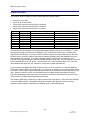
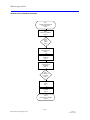
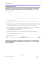
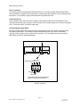
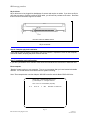
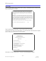
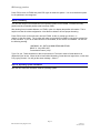
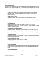
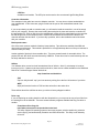
IBM storage products
Installation guide
Ultrastar 18ES
Multi-mode SE/LVD
Models:
DNES-309170
DNES-318350
IBM storage products
Table of contents
Introduction . . . . . . . . . . . . . . . . . . . . . . . . . . . . . . . . . . . . . . . . . . . . . . . . . . . . . . . . . . . . . . . Page 3
Hardware description . . . . . . . . . . . . . . . . . . . . . . . . . . . . . . . . . . . . . . . . . . . . . . . . . . . . . . . . Page 4
Hard disk drive handling guide . . . . . . . . . . . . . . . . . . . . . . . . . . . . . . . . . . . . . . . . . . . . . . . . Page 5
Hard disk drive installation flow chart . . . . . . . . . . . . . . . . . . . . . . . . . . . . . . . . . . . . . . . . . . . Page 6
Step 1: Installation checklist . . . . . . . . . . . . . . . . . . . . . . . . . . . . . . . . . . . . . . . . . . . . . . . . . . Page 7
Step 2: Prepare for installation . . . . . . . . . . . . . . . . . . . . . . . . . . . . . . . . . . . . . . . . . . . . . . . . Page 8
Step 3: Jumper Settings . . . . . . . . . . . . . . . . . . . . . . . . . . . . . . . . . . . . . . . . . . . . . . . . . . . . . . Page 9
Step 4: Mounting . . . . . . . . . . . . . . . . . . . . . . . . . . . . . . . . . . . . . . . . . . . . . . . . . . . . . . . . . . Page 12
Step 5: Connectors . . . . . . . . . . . . . . . . . . . . . . . . . . . . . . . . . . . . . . . . . . . . . . . . . . . . . . . . . Page 13
Step 6: Complete physical installation . . . . . . . . . . . . . . . . . . . . . . . . . . . . . . . . . . . . . . . . . Page 14
Step 7: Installation and configuration . . . . . . . . . . . . . . . . . . . . . . . . . . . . . . . . . . . . . . . . . . Page 14
Step 8: FDISK . . . . . . . . . . . . . . . . . . . . . . . . . . . . . . . . . . . . . . . . . . . . . . . . . . . . . . . . . . . . . Page 17
Step 9: Formatting . . . . . . . . . . . . . . . . . . . . . . . . . . . . . . . . . . . . . . . . . . . . . . . . . . . . . . . . . Page 19
Step 10: Operating system installation . . . . . . . . . . . . . . . . . . . . . . . . . . . . . . . . . . . . . . . . . Page 19
Appendix . . . . . . . . . . . . . . . . . . . . . . . . . . . . . . . . . . . . . . . . . . . . . . . . . . . . . . . . . . . . . . . . . Page 20
Glossary . . . . . . . . . . . . . . . . . . . . . . . . . . . . . . . . . . . . . . . . . . . . . . . . . . . . . . . . . . . . . . . . . Page 26
Page 2
IBM Technical Group Support Center
version 1.1
25L17811G10
IBM storage products
Introduction
This manual was prepared to help you install your IBM Ultrastar 18ES hard drive in most computer
systems. If you do not feel comfortable installing this drive yourself, contact a qualified installer to assist
you.
International Business Machines Corporation provides this publication "AS IS" without warranty of any
kind, either express or implied, including, but not limited to, the implied warranties of merchantability or
fitness for a particular purpose. Some states do not allow disclaimers of express or implied warranties in
certain transactions. Therefore, this statement may not apply to you.
This publication could include technical inaccuracies or typographical errors. Product data and
specifications are subject to change without notice. Changes are periodically made to the information
herein; these changes will be incorporated in new editions of the publication. IBM may make
improvements or changes in the products or the program described in this publication at any time.
This publication may contain reference to or information about IBM products (machines and programs),
programming, or services that are not available in your country. Such references or information must not
be construed to mean that IBM intends to make available such IBM products, programming, or services in
your country.
Product description data contained herein represents IBM’s design objectives and is provided for
comparison among IBM products; actual results may vary based on a variety of factors. Except as
explicitly stated in the Warranty section of this Guide, the product data contained herein does not
constitute a warranty. Questions regarding IBM warranty terms or the methodology used to derive data
should be referred to an IBM representative.
Technical information about IBM hard disk drive products can be obtained via the Internet at:
http://www.ibm.com/harddrive
or by calling the IBM Hard Disk Drive Technical Support Center at 888.426.5214.
©Copyright International Business Machines Corporation 1999. All rights reserved. Note to US
Government Users - Documentation related to restricted rights - Use, duplication, or disclosure is subject
to restrictions set forth in GSA ADP Schedule Contract with IBM Corp.
IBM is a registered trademark of the International Business Machines Corporation. The following are also
trademarks or registered trademarks of the International Business Machines Corporation in the United
States, other countries, or both: Ultrastar and OS/2. Any other products or trademarks are the property of
their respective owners.
Page 3
IBM Technical Group Support Center
version 1.1
25L17811G10
IBM storage products
Hardware description
The Ultrastar 18ES is available in various models with the following options:
!
!
!
!
!
Capacity of 18 or 9GB
50, 68, or 80 pin connectors
50 pin SCSI connectors use the SCSI A connector.
68 pin SCSI connectors use the SCSI P connector.
80 pin SCSI connectors use the SCA-2 connector
Capacity
9GB
9GB
9GB
9GB
18GB
18GB
18GB
18GB
Model
DNES-309170
DNES-309170
DNES-309170
DNES-309170
DNES-318350
DNES-318350
DNES-318350
DNES-318350
SCSI Pins/Connector Type
50 / Unitized Connector
68 / Unitized Connector
68 / Unitized Connector
80 / SCA-2
50 / Unitized Connector
68 / Unitized Connector
68 / Unitized Connector
80 / SCA-2
SCSI Electrical Signal Type
Ultra SCSI
Ultra SCSI
Low Voltage Differential (Ultra2)
Low Voltage Differential (Ultra2)
Ultra SCSI
Ultra SCSI
Low Voltage Differential (Ultra2)
Low Voltage Differential (Ultra2)
These drives offer an advanced LVD interface that supports transfer rates of up to 80 MB/sec. To take
advantage of the higher transfer rate of 80 MB/sec, your computer will need to have a controller that
supports the LVD interface. If you have a SCSI controller that does not support this interface, the drive
will still function, but will be limited to data transfer speeds significantly lower than 80MB/sec due to the
lower speed of your controller. If you have a slower controller, you may wish to purchase an LVD
controller card to take advantage of Ultrastar’s 80 MB/sec data transfer rate. An LVD controller card will fit
into any available slot in your computer. To determine if your current controller card is LVD, check the
documentation that came with your controller or contact the controller manufacturer.
If you currently have single-ended wide SCSI drives and a non-LVD controller, you may still attach the
LVD model Ultrastar 18ES to the existing cable. If you choose to replace your non-LVD controller with an
LVD model, in most cases, single-ended wide SCSI drives can be attached to the same bus with an LVD
drive. However, there are some LVD controllers that do not support single-ended wide SCSI drives.
Check the documentation that came with your controller or contact the manufacturer to ensure that your
LVD controller will support single-ended wide SCSI drives.
The Ultrastar 18ES family is ideal use by video producers and movie editors. These drives are designed
to work with MMX systems. Compatibility listings are included in the appendix. Before you begin
installation, please read the “Hard disk drive handling guide” on the following page.
Page 4
IBM Technical Group Support Center
version 1.1
25L17811G10
IBM storage products
Hard disk drive handling guide
These notes are designed to provide a simple overview of the need for caution when handling a disk drive.
Disk drives can be easily damaged by electrical static shock or rough handling. In order to minimize the
risk of damage to a disk drive, it is essential that the drive be handled while resting on a cushioned surface
(which is electrostatically safe). Examples of static-safe mats available at the time of this printing are
3M's 8210 table mat and 3M's "First Touch" computer pad.
Great care should be taken when handling disk drives. Do not bump them against any object. When
attaching brackets or mounting the drive in the computer, be very careful. It is very easy to unintentionally
cause shocks which exceed specifications.
Please note that the capacity of each disk drive to withstand electrical or mechanical shock varies
according to its design. The IBM Hard Disk Drive Technical Support Center can advise you on the
suitability of your Ultrastar drive for a specific application.
Damage incurred to a drive might not be immediately evident and could cause the drive to fail months
later.
Page 5
IBM Technical Group Support Center
version 1.1
25L17811G10
IBM storage products
Hard disk drive installation flow chart
Step 1
Installation checklist/assemble
needed equipment
Page 7
Step 2
Prepare for installation
Page 8
Step 3
Jumper
settings
Page 9
Step 4
Mounting the drive
Page 12
Step 5
Connectors
Page 13
Step 6
Complete physical
installation
Page 14
Step 7
Installation and
configuration
Page 14
Step 8
FDISK
Page 17
Step 9
Formatting
Page 19
Step 10
Operating system installation
Page 19
Page 6
IBM Technical Group Support Center
version 1.1
25L17811G10
IBM storage products
Step 1: Installation checklist
To install the Ultrastar drive you may need the following items, depending on your computer’s
components:
!
The installation kit (as shown in the diagram below) containing the Ultrastar drive, 4 mounting
screws, and any related publications. Save the box the drive came in.
Screwdriver
Hard Drive
Installation
Guide
Jumpers
Screws
Installation Guide
!
The documentation that came with your computer or storage enclosure.
!
A small, flat-blade screwdriver.
!
A SCSI controller, which is either built-in or an adapter inside your computer, and any related
documentation.
!
Mounting brackets, if required for your computer. Contact your place of purchase if you
are not certain if mounting brackets are required.
!
A bootable DOS diskette. (See the section entitled Making a bootable diskette in the
appendix.)
!
If you are replacing an older internal drive with the new Ultrastar drive and want to copy all of the
files from the older drive to the new drive, you may need additional software. (See the section
entitled Drive copy in the Appendix.)
Page 7
IBM Technical Group Support Center
version 1.1
25L17811G10
IBM storage products
Step 2: Prepare for installation
Begin by backing up your existing drive to avoid any loss of data during installation. (See the section
entitled Backup and Restore in the Appendix.) After completing the backup, shut down as normal.
Opening your computer
!
Turn the system off.
!
Unplug the power cord from the wall outlet.
!
Remove all cables from the back of your computer, labeling them if necessary.
!
Remove the cover from your computer. (Consult your user's guide for instructions if needed.)
Unpackaging your hard drive
!
If available, use an ESD (Electronic Static Discharge) wrist strap while handling your drive.
!
If an ESD wrist strap is not available, discharge static electricity by establishing a common voltage
between your body and the hard drive. Simultaneously touch the hard drive in its antistatic bag and
an unpainted metal surface on the outside of your computer system with your bare hands.
!
Remove the drive from the antistatic package that it was shipped in. Handle the drive only by the
sides and avoid excessive movement until the drive has been mounted.
!
Do not touch the main computer chip board.
!
Do not drop the drive. A drop from only 1/4 inch could permanently damage your hard drive.
!
Place the drive carefully on a static free area.
!
Record the following information:
Drive Model ________________
P/N __________________
____________________
Date of Purchase_________________
Place of Purchase_________________
Drive
Serial #
Note:Do not low-level format your drive! IBM drives are low-level formatted by the manufacturer and
reformatting may cause permanent damage to your drive and your system. (See the section entitled
Utilities in the Appendix.)
Page 8
IBM Technical Group Support Center
version 1.1
25L17811G10
IBM storage products
Step 3: Jumper settings
The jumper settings are found on the hard drive on the opposite end of the interface connector (see
diagram page 12). They are physical settings that must be changed for different uses of a hard drive. As
shown below, there are two option jumper blocks located on the card of 50 and 68 pin models of the
Ultrastar 18ES. 80 pin models have only one option jumper block.
SCSI ID Jumpers
Each SCSI device will need to have its own SCSI ID. You can use ID 0 through ID 15, reserving ID 7 for
your controller card. Follow the table below to set an ID on your SCSI drive.
Bit 3
off
off
off
off
off
off
off
off
on
on
on
on
on
on
on
on
Bit 2
off
off
off
off
on
on
on
on
off
off
off
off
on
on
on
on
Bit 1
off
off
on
on
off
off
on
on
off
off
on
on
off
off
on
on
Bit 0
off
on
off
on
off
on
off
on
off
on
off
on
off
on
off
on
Address
0
1
2
3
4
5
6
7*
8
9
10
11
12
13
14
15
*Reserved for controller card
SCSI address determination
Page 9
IBM Technical Group Support Center
version 1.1
25L17811G10
IBM storage products
Drive Termination
The SCSI bus must be terminated at both ends of the bus. If you have a single-ended Ultrastar 18ES,
active termination is supplied on the jumper block. Ultra2 SCSI (LVD) models do not have onboard active
termination. You will need to supply an external Ultra2 compatible terminator.
Termination Power
Some controllers may require the drive to supply 5 volts of power to the bus to aid termination. If your
controller requires this, place a jumper on the Termination Power Enable jumpers to the side of the jumper
block. These pins require a 2.54mm jumper shunt.
Auxiliary Option Jumper Block
The 68 pin models contain an auxiliary connector that replicates some of the functions provided by the
front option jumper block. The auxiliary connector should only be used if you have a combination
“ganged” switch, typically found in external drive enclosures. The front option block and the auxiliary
option block may not be used simultaneously.
Auxiliary Connector
::::::
SCSI Address
Enable SCSI Terminator ID2 ID0
+5V
ID3
ID1
11 9
7
5 3 1
12 10 8
6 4 2
Reserved
Reserved
Ground
LED Cathod
Note: Pin #9 is valid only for single-ended model.
LVD/SE mult-mode model has no terminator.
Auxiliary connector
Page 10
IBM Technical Group Support Center
version 1.1
25L17811G10
IBM storage products
Additional Jumper Options
The Ultrastar drives offer additional options on the jumper block. See Appendix for details of the additional
jumper options shown below.
Option Jumper Block J-4
Option Jumper Block J-6
SCSI Bus
Open
LED Anode
Ground
12 11 10 9 8
7
6
5 4
3
2
1
0 1 2 3
SCSI ID Bits
Enable Auto Spin Up
LED Cathod
Disable SCSI Parity Check
Delay Start 6/12
G F E
Ground
D C B A
Open Reserved
Enable Terminator
Power Supply
Enable SCSI Terminator
Disable Unit Attention
Enable Auto Start Delay
Enable TI-SDTR/WDTR
*80 pin models do not have Option Jumper Block J-6
*Position #6 is "Force Single-ended Mode" on multi-mode SE/LVD
models.
Jumper settings for single-ended models
Option Jumper Block J-4
Option Jumper Block J-6
SCSI Bus
Open
LED Anode
Ground
12 11 10 9 8
7
6
5 4
3
2
1
0 1 2 3
SCSI ID Bits
Enable Auto Spin Up
LED Cathod
Disable SCSI Parity Check
Delay Start 6/12
Enable Auto Start Delay
G F E
Ground
D C B A
Open Reserved
Enable Terminator
Power Supply
Force SE Mode
Disable Unit Attention
Enable TI-SDTR/WDTR
*80 pin models do not have Option Jumper Block J-6
Jumper settings for Ultra2 SCSI (LVD) models
Page 11
IBM Technical Group Support Center
version 1.1
25L17811G10
IBM storage products
Step 4: Mounting
After setting the jumpers, mount the hard drive in your system. The Ultrastar drive can be mounted with
any of its six surfaces facing down. See below for mounting hole locations.
Mounting hole locations
You must ensure that the drive has sufficient air flow. Mount the drive in the system using four 6-32 UNC
screws. The maximum screw length is 3.5 mm for the side holes and 6 mm for the bottom holes. Mount
the drive securely enough to prevent excessive motion or vibration.
If you are mounting your drive in a 5 inch bay, you may need to purchase mounting brackets from your
computer manufacturer for the drive to be mounted securely.
Page 12
IBM Technical Group Support Center
version 1.1
25L17811G10
IBM storage products
Step 5: Connectors
50 and 68 pin drives
After the drive has been carefully mounted, connect the SCSI cable and the power cable to the drive.
(Note that the SCSI connector and power connector are keyed for proper insertion.)
50 pin connector
68 pin connector
Page 13
IBM Technical Group Support Center
version 1.1
25L17811G10
IBM storage products
80 pin drives
80 pin drives are to be plugged into backplanes of servers and require no cables. If you have an 80 pin
drive that you want to connect to a 68 pin SCSI cable, you will need to purchase a converter. Be aware
that not all SCA converters support LVD mode.
80 pin connector
Step 6: Complete physical installation
Verify that the cable is properly connected to the SCSI controller. Replace the cover on the computer,
connect all cables, and plug the power cord into the wall.
Step 7: Installation and configuration
If you have just added a SCSI controller card, follow the manufacturer’s instructions to install the card.
Boot computer
“Booting” means turning on your computer. Turn on your computer after you have inserted a bootable
diskette. You should see the drive listed when the system is booting.
Note: The example below uses the Adaptec 3950U2B controller and the Model DRVS-09D drive.
Adaptec AHA - 3950U2B SCSI BIOS v2.10.0
(c) 1998 Adaptec. Inc. All Rights Reserved.
Press <Ctrl> <A> for SCSISelect (TM) Utility
Ch A.
SCSI ID:
0
IBM
DRVS09D ULTRA2-LVD
Page 14
IBM Technical Group Support Center
version 1.1
25L17811G10
IBM storage products
You can, at this time, press [CTRL] [A] to enter the Adaptec SCSI setup utility. The following screen will
appear.
Adaptec AHA-3950U2B SCSISelect (TM) Utility v2.10.0
AHA-3950U2B at Bus: Device 00:Fh
Would you like to configure the host adapter, or run the SCSI disk utilities.
Select the option and press Enter. Press F5 to switch between color
and monochrome modes.
Options
Configure/View Host Adapter Settings
SCSI Disk Utilities
Select the channel to which your drive is attached. The screen below will follow.
Adaptec AHA-3950U2B SCSISelect (TM) Utility v2.10.0
You have an AHA-3950U2B
SCSI host adapter in your system. Move
the cursor to the bus:device:channel of the
one to be configured and press <Enter>.
Bus:Device:Channel
00:0D:A
00:0D:B
<F5> - Toggle color/monochrome
Arrow keys to move cursor, <Enter> to select option, <Esc> to exit ( * = default)
Page 15
IBM Technical Group Support Center
version 1.1
25L17811G10
IBM storage products
Select the first option Configure/View Host Adapter Settings. The next screen is shown below with the
default settings.
Adaptec AHA-3950U2B SCSISelect (TM) Utility v2.10.0
AHA-3950U2B at Bus:00h Device:0Dh Channel:B
Configuration
Host Adapter SCSI ID..................................................................................... 7
SCSI Parity Checking..................................................................................... Enabled
Host Adapter SCSI Termination...................................................................... Automatic
Boot Device Options....................................................................................... Press <Enter>
SCSI Device Configuration............................................................................. Press <Enter>
Advanced Configuration Options.....................................................................Press <Enter>
<F6> - Reset to Host Adapter Defaults
BIOS Information
Interrupt (IRQ) Channel.........................................................................................10
I/0 Port Address.....................................................................................................F400h
Arrow keys to move cursor, <Enter> to select option, <Esc> to exit ( * = default)
You can accept the default settings with Host Adapter SCSI Termination set to Automatic. If you wish to
accept the default settings, press [ESC] to return to the previous menu. Select the SCSI utilities.
Adaptec AHA-3950U2B SCSISelect (TM) Utility v2.10.0
AHA-3950U2B at Bus:00h Device:0Dh Channel:A
Select SCSI Disk and press <Enter>
SCSI ID #0:
IBM
SCSI ID #1:
No device
DRVSO9D
SCSI ID #2:
No device
SCSI ID #3:
No device
SCSI ID #4:
No device
SCSI ID #5:
No device
SCSI ID #6:
No device
SCSI ID #7:
AHA-3950U2B
SCSI ID #8:
No device
SCSI ID #9:
No device
SCSI ID #10:
No device
SCSI ID #11:
No device
SCSI ID #12:
No device
SCSI ID #13:
No device
SCSI ID #14:
No device
SCSI ID #15:
No device
ULTRA2-LVD
Arrow keys to move cursor, <Enter> to select option, <Esc> to exit (*=default)
This shows all devices attached to the bus. To perform a Verify Media, highlight the drive you would like
to verify and press [ENTER]. Select Verify Media from the options.
If you wish to accept all settings, press [ESC] to exit out of the Adaptec settings.
Page 16
IBM Technical Group Support Center
version 1.1
25L17811G10
IBM storage products
Step 8: FDISK
Boot to a bootable diskette and type FDISK at the A:\ prompt. If Windows® 95 OSR2 or Windows® 98 is
used, the following screen will appear.
Your computer has a disk larger than 512 MB. This version of Windows
includes improved support for large disks, resulting in more efficient use of
disk space on large drives, and allowing disks over 2 GB to be formatted as
a single drive.
IMPORTANT: If you enable large disk support and create any new drives on
this disk, you will not be able to access the new drive(s) using other operating
systems, including some versions of Windows 95 and Windows NT, as well as
earlier versions of Windows and MS-DOS. In addition, disk utilities that were
not designed explicitly for the FAT32 file system will not be able to work with
this disk. If you need to access this disk with other
operating systems or older disk utilities, do not enable large drive support.
Do you wish to enable large disk support (Y/N)...............? [N]
Type Y to select the FAT 32 file system. Type N to select the FAT 16 file system.
The following screen allows you to create partitions. If you have more than 1 drive there will be 5 options.
Option 5 allows you to select the drive you wish to partition.
PC DOS Version 7.0
Fixed Disk Setup Program
Copyright IBM Corporation 1983-1994
FDISK Options
Current fixed disk drive:
1
Choose one of the following:
1. Create DOS partition or Logical DOS Drive
2. Set active partition
3. Delete partition or Logical DOS Drive
4. Display partition information
5. Change current fixed disk drive
Enter choice:[1]
Press ESC to exit FDISK
Select option 1 to create a DOS partition. The screen on the following page will appear.
Page 17
IBM Technical Group Support Center
version 1.1
25L17811G10
IBM storage products
Select option 1 to create a DOS partition. The screen below will appear.
Create DOS Partition or Logical DOS Drive
Choose one of the following:
1. Create Primary DOS Partition
2. Create Extended DOS Partition
3. Create Logical DOS Drive(s) in the Extended DOS partition.
Enter choice: [3]
Press ESC to return to FDISK Options
Select option 1 to Create a Primary DOS Partition. If this is to be the boot drive, set this partition to
“Active”.
Press ESC to return to the FDISK options. Create an Extended DOS Partition by selecting option 1 from
the main menu and option 2 from the second menu. (Both menus shown above.)
Note: The Maximum Capacity shows only 8455 MB instead of 9130 MB. This is because the BIOS of
some systems recognizes a Megabyte as 1,048,576 bytes (binary). Drive manufacturers recognize a
Megabyte as 1,000,000 bytes (decimal). The capacities are the same in actual number of bytes.
After creating the Extended DOS Partition, press ESC to return to the FDISK main menu. Select option 1
to create a Logical DOS Drive, then option 3 to create a Logical DOS Drive in an Extended Partition.
Create Logical DOS Drive(s) in the Extended
DOS Partition
No logical drives defined
Total Extended DOS Partition size is 1047 Mbytes
(1 MByte = 1048576 bytes)
Maximum space available for logical drive is 1047Mbytes (100%)
Enter logical drive size in Mbytes or percent of disk space (%).....[1047]
Press ESC to return to FDISK Options
Page 18
IBM Technical Group Support Center
version 1.1
25L17811G10
IBM storage products
Press ESC to return to FDISK and press ESC again to restart the system. You must restart the system
for the partitions to be recognized.
Step 9: Formatting
The drive will need to be formatted before an operating system can be loaded. Format the Primary
partition and any Extended partitions that have been made.
After booting from a bootable diskette, run FDISK, option 4 to display the partition information. This is
helpful to review drive letter assignments. Note the drive letters to ensure proper formatting.
Press ESC to return to the main menu and exit FDISK. At the A:\ prompt type format x: /s
(where x is the drive letter). The /s option will make your hard drive bootable by copying the system files
to the hard drive. If you do not want this drive to be bootable, do not use the /s command. You will see
the following warning:
WARNING: ALL DATA ON NON-REMOVABLE DISK
DRIVE C: WILL BE LOST!
Proceed with Format (Y/N)?
Type Y for yes. There should be no data on the new drive. The time it takes to format the drive is
dependent upon its size. When the drive has finished formatting, format the next logical drive, in this case
D: by typing format d: You will get the same message. Select Y.
Step 10: Operating system installation
After the drive has been formatted, install an operating system.
Page 19
IBM Technical Group Support Center
version 1.1
25L17811G10
IBM storage products
Appendix
Making a bootable diskette
If you do not have a DOS bootable diskette, you may want to make one. This will be necessary for
installing your new hard disk drive and in case of system failure. The DOS bootable diskette will contain
files necessary to boot your system. These files are called system files. You will also want some utilities
on your bootable diskette. Following are the instructions needed to add both the system files and the
other helpful utilities.
!
Make sure your computer is on and you insert a diskette in drive A.
!
At the C:\ prompt, type FORMAT A: /S and press [ENTER].
!
Press [ENTER] again, unless you want to label your diskette.
!
Add the utilities. To do so, use some simple copy commands.
"
"
"
"
"
"
Type cd Windows at the C:\ prompt, press [ENTER].
Type copy fdisk.exe a:, press [ENTER].
Type copy format.com a:, press [ENTER].
Type copy sys.com a:, press [ENTER].
Type copy chkdsk.exe a:, press [ENTER].
Type copy debug.exe a:, press [ENTER].
!
Type cd.
!
Remove diskette from drive A:
!
Write protect the diskette by sliding the small plastic tab on the diskette in the up position.
!
Test the diskette.
"
"
"
"
!
Turn off your computer.
Insert the diskette in drive A:
Turn on your computer.
When you get to the A:\ prompt type c:, press [ENTER].
If any of these steps did not work, start again at step 1.
Page 20
IBM Technical Group Support Center
version 1.1
25L17811G10
IBM storage products
Jumper block information
The jumper block is a block of pins located on the hard drive. When these pins are shorted with shunts
(jumpers), the drive will behave in certain ways. A shunt is a small piece of plastic with metal inside that
shorts out the connection between 2 pins when placed over them. These can be purchased at any local
computer store. The pin pitch for all pins except for Termination Power is 2 mm. Termination Power pins
have a pitch of 2.54mm.
Disable Auto Spin Up
Available on 80 pin models. When a jumper is installed, the drive will spin up automatically
after power on reset. If a jumper is installed, the drive will not spin up unless a Start Unit
command is received.
Disable SCSI Parity Check
Available on all models. When a jumper is installed, SCSI Parity checking is disabled.
Disable Unit Attention Pin
Available on all models. When a jumper is installed, the drive will not be able to send Unit
Attention Sense information for commands immediately following a Power On Reset or SCSI Bus
Reset.
Enable Auto Spin Up
Available on 50 and 68 pin models. When a jumper is installed, the drive will spin up
automatically after a power on reset. If a jumper is not installed, the drive will not spin up unless
a Start Unit command is received.
Enable Auto Start Delay/Delay Start 6/12
Available on all models. The Auto Start and Auto Start Delay pins control when and how the
drive can spin up and come ready with the combination of the Enable Auto Spin Up jumpers.
When both Auto Spin Up and Auto Start Delay are enabled, the drive start will be delayed by a
period of time multiplied by the drive’s SCSI address. If Auto Spin Up is disabled, these jumpers
will be ignored.
Enable SCSI Terminator
Available on 50 and 68 pin single-ended models. If a jumper is installed, the internal SCSI active
terminator on the drive will function.
Enable Terminator Power Supply
Available on 50 and 68 pin models. Term Power is enabled.
Enable TI-SDTR
Available on 50 pin models. When a jumper is installed, Target Initiated Synchronous Data
Transfer Request Negotiation is enabled.
Enable TI-SDTR/WDTR
Available on 68/80 pin models. When a jumper is installed, Target Initiated Wide Data Transfer
Request Negotiation and Target Initiated Synchronous Data Transfer Request Negotiation are
enabled.
Force Single Ended Mode
Available on 68 and 80 pin LVD models. If a jumper is installed, the drive is forced to work in
single-ended mode.
Page 21
IBM Technical Group Support Center
version 1.1
25L17811G10
IBM storage products
LED Pins
Available on all models. The LED pins can be used to drive an external Light Emitting Diode.
Controller information
The examples in this guide have used an Adaptec controller. You may have a chipset embedded into
your motherboard. If this is the case, plug the cable into the port on the motherboard instead of the
controller.
If you are purchasing an add-on controller card, you will need to install the controller in one of the empty
slots in your computer. Remove the screw holding the metal plate in place and insert the controller into
the appropriate PCI, EISA or ISA slot on the motherboard, making sure the metal plate from the controller
fits into the grooves on the computer frame. Replace the screw and connect the SCSI cables to the
controller and then the hard drive. If you have any questions, refer to the installation manual enclosed
with your controller.
Backup and restore
One of the most common methods of backup is tape backup. Tape drives are available from IBM and
other major manufacturers. This method is preferred for overnight backups that run while your business is
closed or while you sleep.
Another method of backup is the removable drive. There are several brands of removable drives. The
popular ZIP and JAZ drives are manufactured by IOMEGA. These drives can be used for backup and can
be easily attached or removed.
Utilities
Your Ultrastar drive comes low-level formatted and free of defects. Note: Do not attempt to low-level
format your drive. If data must be removed from the drive, there are two utilities available on the IBM Hard
Disk Drive Technical Support Center Web site at:
http://www.ibm.com/harddrive
.
ZAP
Zap is a utility that will “zap” your boot sector by writing 0’s to the first 128 sectors of your drive.
WIPE
Wipe performs the function of ZAP and also writes 0's to the entire drive.
These utilities should be sufficient to return your drive to factory-shipped condition.
Drive copy
If you are replacing an existing hard drive with the Ultrastar drive, you may want to copy all your files from
the existing drive to the Ultrastar. There are several software programs available that copy one drive to
another.
PowerQuest Drive Copy 2.0
http://www.powerquest.com/product/dc.index.html
This utility supports all operating systems, has mouse support, selective partitioning, selective
sector copying, and automatically creates a new DOS reboot disk. This utility is not limited by
drive size.
Page 22
IBM Technical Group Support Center
version 1.1
25L17811G10
IBM storage products
QuarterDeck Systems DiskClone
http://www.qdeck.com/qdeck/products/diskclone/indexreg.html
This utility supports all operating systems and has mouse support.
ITS Systems EZ-Upgrader
http://www.itechs-systems.com/
This utility can be used with Windows® 3.1 andWindows® 95 operating systems.
Image Systems Solutions Drive-to-Drive
http://www.img-systems.com/d2ddesc.htm
This utility is for use with all operating systems, but is limited to copying drives with similar
physical geometry.
FWB software Drive Up!
http://www.fwb.com/
This utility is used with Windows® operating systems only.
Page 23
IBM Technical Group Support Center
version 1.1
25L17811G10
IBM storage products
Compatibility matrix
The IBM SIT Lab thoroughly tests Ultrastar drives for compatibility with a wide variety of systems,
controller cards, and operating systems. Testing was done to demonstrate compatibility with the following
hardware and software. Other combinations of hardware and software may function with this drive, but
were not tested.
Systems
ACER AP53A\P5-166 430HX
ASUS P2B-LS
ASUS BIOS V4.51 PG
Apple 6400/180
Aopen Ax6B
Compaq DeskPro EN6400
Dell Dimension XPS R450
Dell OptiPlex Gx1
Dell Precision 410
Dell PowerEdge 2300/350
Digital PC 5500
FIC PA-2013
Gateway G6-450
Gigabyte GA-6BxS
HP Kayak XA6/300MT
HP Kayak XU
HP9000 Workstation
IBM systems
ICL/Fujitsu G60i
Intel N440BX
Intel MU440EX
Micron Millenia Endeavor
Micron Powerdigm XSU
NEC Direction SPL 266
SGI 02
SGI Origin 200
SNI Primergy
Shuttle HOT-591 SpaceWalker
Tyan 1572ATX/430TX P5-200
DPT PM 2044W
IBM NCR 53C825
Initio INT-9100 UW
Mylex AcceleRAID 250
Mylex DAC 960PD
Qlogic QLA-1080
SIIG Ultra SCSI Pro PCI
Symbios SYM53C876
Symbios SYM8951U
Operating systems
HP-UX 10.20
IRIX 6.3
MS DOS v6.22
Novell Netware v4.11
OS/2 v4.0
PC DOS v6.3
SCO Open Server v5.0
SUN OS 5.4 / 5.5.1
SCO UNIXWARE
SUN OS 5.4 / 5.5.1
Windows 95
Windows 98
Windows NT v4.0
Windows NT v5.0 (beta)2
SCSI controllers
Adaptec AHA-2940U2W
Adaptec AHA-2940UW
Adaptec AHA-2950U2B
Adaptec AHA-3940UW
Adaptec AHA-3950U2B
Adaptec AIC-7890B
Adaptec AIC-7880
Adaptec AHA-131
AdvanSys ABP940
Buslogic BT-958
Buslogic BT956C
Dell PERC 2/SC
Dell PERC ll
DIAMOND Fireport 40
Page 24
IBM Technical Group Support Center
version 1.1
25L17811G10
IBM storage products
Technical support
Before calling technical support make sure you have your drive part number, serial number, and system
information.
Contact technical support via:
Web
Voice
Fax
e-mail
www.ibm.com/harddrive
888.426.5214 or 507.286.5825
507.253.4111
[email protected]
Support is also available in Singapore at:
Voice
e-mail
1800.418.9595 or (65) 6.418.9595
[email protected]
Automated Fax Back Service
U.S.A.
Singapore
England
Germany
France
Italy
408.256.5218
800.418.9696
0800.96.6948
0130.82.6089
0800.902229
167.875148
Page 25
IBM Technical Group Support Center
version 1.1
25L17811G10
IBM storage products
Glossary
ANSI (American National Standards Institute)
ANSI is the lead organization for encouraging and developing technological standards. ANSI represents
the United States in the IEC (International Electrotechnical Commission) and the ISO (International
Standards Organization).
Backup
Storing information from a hard drive to another storage area in order to prevent data loss. Tape
drives and Zip drives (IOMEGA) are two common mediums for saving vital information contained on a
hard drive.
BIOS (Basic Input/Output System)
The BIOS is the first level of software contained in a computer. It provides basic, low level control for
keyboards, video, hard disk drives, and floppy drives. It also provides the initial intelligence that allows the
computer system to find an operating system to run.
Boot/Boot-up
To prepare a computer for operation by loading an operating system.
Capacity
The amount of information, expressed in bytes, that can be stored on a hard drive. Also known as storage
capacity.
Compatibility
The capability of a hardware or software component to conform with the interface requirements of a given
data processing system without adversely affecting its functions.
Cylinder
1) In an assembly of magnetic disks, the set of all tracks that can be accessed by all the magnetic heads
of a comb in a given position. 2) The tracks of a disk storage device that can be accessed without
repositioning the access mechanism.
Disk drive
The primary data storage device used by computers. Disk drives are used to record, store and retrieve
digital information.
Electrostatic discharge
The rapid change in electrical energy caused by static electricity. This can damage or destroy electronic
equipment or hardware. Electrostatic discharge can be prevented by grounding oneself before handling
any electronic equipment.
FAT16/FAT32 (File Allocation Table)
The file allocation table is a group of sectors in a hard drive that contains address chains for the different
files on a hard disk drive. There are usually two FATs (kept in different locations) on a hard drive. FAT32
is available in the Windows® 95 & Windows® 98 operating systems. FAT32 receives its designation
because it allows 32 bits of addressing as opposed to 16 bits in the FAT16 file system.
FDISK
FDISK is a program run in DOS that allows a user to partition a hard disk drive. Partitioning your hard disk
drive is essential for it to work properly.
Page 26
IBM Technical Group Support Center
version 1.1
25L17811G10
IBM storage products
Format
To prepare a hard drive so that it can store data. In the DOS formatting process, the computer verifies the
clusters within a partition.
FTP (File Transfer Protocol)
In the Internet suite of protocols, an application layer protocol that uses TCP and Telnet services to
transfer bulk-data files between machines or hosts.
Hard disk drive (HDD)
A stand alone disk drive that reads and writes data onto rigid disks and can be attached to a port on the
system unit. Synonymous with fixed disk drive and hard drive.
Head
The tiny electromagnetic coil and metal pole used to create and read back magnetic patterns on the disk.
HPFS (High Performance File System)
The file system used by the OS/2 operating system.
Interface
A hardware or software protocol, contained in the electronics of the disk controller and drive, that
manages the exchange of data between the hard disk drive and the computer. The most common
interfaces for small computer systems are ATA (IDE) and SCSI.
Jumpers
Small pieces of plastic with a conductive center used to connect pins on a device.
Jumper settings
Different modes which are achieved by placing the jumper on particular pins on a device. These modes
determine the behavior of the device. Settings are changeable by the user, but remain constant during
operation. See Jumpers.
LVD (Low Voltage Differential)
A highly compatible computer disk drive interface that is faster and more reliable than SCSI. Also known
as Ultra2SCSI.
Motherboard
Holds the computer's main processors and circuitry, and also contains thememory, BIOS, interconnection
circuitry and expansion slots.
Multi-mode
A drive that can operate on an LVD bus or a Single-ended bus.
NTFS (NT File System)
An advanced file system used by the Windows NT operating system.
Operating system
Software that controls the execution of programs and may provide functions such as resource allocation,
scheduling, input/output control, and data management. Although operating systems are predominantly
software, partial hardware implementations are possible.
OS/2
A fully preemptive, multitasking operating system developed by IBM. OS/2 also supports HPFS.
Page 27
IBM Technical Group Support Center
version 1.1
25L17811G10
IBM storage products
Partition
A portion of a hard drive dedicated to a particular operating system or application and accessed as a
single logical volume.
SCSI (Small Computer System Interface)
Pronounced “scuzzy”. An intelligent parallel peripheral interface characterized by its use of high level
communication between devices.
Sector
On a hard drive, the minimum segment of track length that the hard disk drive can assign to store
information.
Termination
The signals on a SCSI bus must be terminated at both ends of the bus. This is generally done
automatically by the controller and requires an “external” terminator on the last connector of the bus.
Track
One of the many concentric magnetic circle patterns written on a disk surface as a guide for storing and
reading data.
Wipe
Wipe is a software utility that writes zeros to every sector on a hard disk drive up to 8 GB. See Zap.
Windows® NT
Microsoft’s 32-bit server operating system.
Windows® 98
Microsoft operating system.
Zap
A utility in which the first 128 sectors of a hard drive are overwritten with zeros. See Wipe.
Zip drive
A drive which uses increased real density on floppy disk technology to increase storage capacity. Zip
diskettes have a storage capacity of 100 MB.
Page 28
IBM Technical Group Support Center
version 1.1
25L17811G10
IBM storage products
®
© International Business Machines Corporation 2001
www.ibm.com/harddrive
IBM Technical Group Support Center
Dept. WCN
3605 Highway 52 North
Rochester, MN 55901
Telephone: 888.IBM.5214 or 507.286.5825
Fax: 507.253.DRIVE
E-mail: [email protected]
Singapore Technology Group Support Center
Telephone: 1800.418.9595 or 65.6.418.9595
E-mail: [email protected]
UK Technology Group Support Center
Telephone: 44.1475.898.125
E-mail: [email protected]
Germany Technology Group Support Center
Telephone: 49.7032.153050
E-mail: [email protected]
IBM Storage Technology Division
5600 Cottle Road
San Jose, CA 95193
www.ibm.com/storage
Printed in the United States of America
08-2001
All Rights Reserved
IBM and Ultrastar are registered trademarks of International Business
Machines Corporation.
Other company, product, and service names may be trademarks or
service marks of others.
Produced by the IBM Technology Group Support Center.
IBM products use industry standard interfaces and are generally
compatible with standard Systems, System Boards, SCSI Controllers,
Operating Systems, and BIOS. This is not meant to be a complete list
of compatible products. This information is believed to be accurate,
but is supplied without guarantee.
Document subject to change without notice.
Date: 31 August 2001
Page 29
IBM Technical Group Support Center
version 1.1
25L17811G10