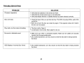
1
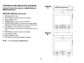
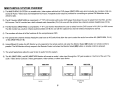
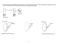
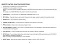
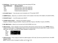
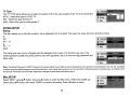
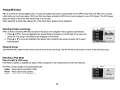
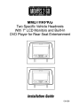
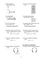
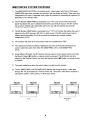
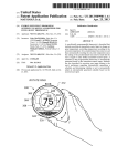
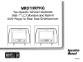
MMD7HRPKG
Two Specific Vehicle Headrests
With 7" LCD Monitors and Built-In
DVD Player for Rear Seat Entertainment
,
(
e=
00 c
(
"0" ::> oo:=J
~00
~
\...
II
..
II
(
c...
I
.:::=>
I
)
oo:=J
..J
\...
II
II
Operation
Manual
128-8281
IMPORTANT
Installation of headrest products require careful planning and preparation. Be extremely careful of seats that have airbags
built into them. Keep wiring away from any air bag wiring (usually identified by yellow connectors and yellow wire jackets).
Damage to air bag wiring can result in personal injury to vehicle occupants. If you have any questions regarding wire
routing or installation in avehicle, please contact Audiovox Technical Support at 1-800-225-6074.
When connecting power and ground in amobile video installation, insure that the ACC wire is fused at the point where it is
connected to the vehicle ACC wiring. Failure to do so can result in damage to the vehicle if ashort circuit develops
between the vehicle connection point and the mobile video product.
An LCD panel and/or video monitor may be installed in amotor vehicle and visible to the driver if the LCD panel or video
monitor is used for vehicle information, system control, rear or side observation or navigation. If the LCD panel or video
monitor is used for television reception, video or DVD play, the LCD panel or video monitor must be installed so that these
features will only function when the vehicle is in "park" or when the vehicle's parking brake is applied.
An LCD panel or video monitor used for television reception, video or DVD play that operates when the vehicle is in gear
or when the parking is not applied must be installed to the rear of the driver's seat where it will not be visible, directly or
indirectly, to the operator of the motor vehicle.
Licensed under one or more of the following patents:
Patent NOS. 7245,274 and 6,899,365
MMD7HRPKG
The MMD7HRPKG contains two headrests. The master unit M1 (MMD7HRM) has a built-in DVD player and the satellite unit M2
(MMD7HRS) has a monitor that is used to either watch the DVD movie that is playing in the master unit or a video source plugged into the
AUX jack on the front of the unit. The full function remote control can operate either unit by selecting M1 or M2 on the remote. Each monitor
has an AUX input and wired headphone jack on the bottom right hand side of the screen.
~uick
1.
2.
3.
4.
5.
6.
7.
8.
9.
Start Guide
Turn on the M1 (MMD7HRM) monitor, tilt the screen forward using the center tab at the top of the screen.
Insert a DVD, CD or MP3 disc into the slot, disc label toward driver.
The disc will start playing.
Tilt the monitor to a comfortable viewing position (the headrest itself can be tilted forward to help achieve a comfortable viewing
position).
Optional wireless headphone has a CH A/CH B switch. When sitting in front of the M1 screen, use the CH A switch setting. When
sitting in front of the M2 screen, use the CH B switch setting. Set the headphone to the proper channel and press the Power On/Off
switch. The power indicator will light up red. Turn the volume down to its lowest setting before putting them on your head.
When the DVD menu appears on the M1 monitor, select the menu item using the cursor keys and press the Enter or Play button.
Turn on the MMD7HRS monitor using the power button on the front of the screen or remote control.
Tilt the screen to a comfortable viewing position (the headrest itself can be tilted forward to help achieve a comfortable viewing
position).
Select AV1 using the source button on the front panel or remote control to view program material on the M1 monitor or select AUX
for M2 monitor.
NOTE: To operate the MMD7HRM screen, press M1 on the remote control.
To operate the MMD7HRS screen, press M2 on the remote control.
3
CONTROLS AND INDICATORS DIAGRAM
MMD7HRM
M1
Control Function Descriptions for MMD7HRM and
MMD7HRS Monitor
I~
==J
c
q>..."
~
ot:
MMD7HRM / MMD7HRS Panel Control
1. DVD disc insertion slot
2. EJECT Button - Press this button to eject the disc.
3. Power Indicator LED
4. POWER Button - Press to turn the unit ON/OFF.
5. SCREEN MODE Button- Press this button to select between
9
Wide(16:9), Normal(4:3) aspect ratio or screen off (display OFF).
6. PLAY Button - Press this button to start playback.
7. SOURCE Button- Press this button to select between DVD and
3
AUX.
4
5
6
7
8
10 11
- _..
......."'_._c_......... z,......_ _ _.....
_----~. -_._"""="""~
8. STOP Button- Press this button to stop playback.
9. IR Transmitter LEOS
MMD7HRS
M2
10. Wired Headphone Jack
11. AUX Input Jack (use with supplied AV adaptor)
(0
01
c
~
NOTE: 1, 2, 6 & 8 function for MMD7HRM only.
9
3
4
4
5
7
10 11
MMD7HRPKG SYSTEM OVERVIEW
1) The MMD7HRPKG SYSTEM is a versatile audio / video system with built-in DVD player (MMD7HRM only) which includes two monitors, that can
accept an Audio / Video input and independent AUX input. A separate audio output is provided for connecting an optional FM Modulator to the
vehicle's radio.
2) The M1 Monitor (MMD7HRM) is comprised of a 7" TFT LCD monitor with built-in DVD player that allows the user to select from the DVD, and the
AUX source. The M1 monitor has a built-in infrared audio transmitter (CH A) for use with the optional two-channel wireless headphones (CH A).
3) The M2 Monitor (MMD7HRS) is comprised of a 7" TFT LCD monitor that allows the user to select from the DVD source in M1 (AV1) or AUX source.
The M2 monitor has a built-in infrared audio transmitter (CH B) for use with the optional two channel wireless headphones (CH B).
4) The monitors will show all of the functions with the comprehensive OSD.
5) The optional two-channel wireless Headphone sets have an A-B switch that allow the user to select the audio from either M1 (MMD7HRM, CH A)
or M2 (MMD7HRS,CH B).
6) Using different IR codes, the M1 Monitor will only respond to the remote control unit when the Monitor Select (M1) button on remote control is
pressed. The M2 Monitor will only respond to the Remote Control unit when the Monitor Select (M2) button on remote control is pressed.
7) The wired headphones allow the user to listen to audio from the system.
8) The M1 (MMD7HRM) and M2 (MMD7HRS) Monitor will accept an audio / video input through the 1/8" jack located on the front of the unit. The
audio / video device could be a video game system, video camera, or other input device.
MMD7HRS
MMD7HRM
MMD7HRS
CJ CJ
r.. . CD"""""" 0 )
r.. . CD
o
MMD7HRM
CJ CJ
<:CD
)
~
OJ
r....·CD~
HEADPHONE
JACK
AUXIN
5
'v
9) Pivot the screen until a comfortable viewing angle reached. The internal lock limits the screen to a maximum adjustment of 30 degrees from closed
position, the headrest itself can be tilted forward to help achieve a comfortable viewing position.
Inner Ring
Internal Lock
Closed Position
10) Insert disc
11) Eject disc
- D i s c Label
Insert disc
Eject disc
/
MMD7HRPKG: MMD7HRM Monitor only.
MMD7HRPKG: MMD7HRM Monitor only.
6
REMOTECONTROLOPERATION
27
26
25
1
2
4
5
24
23
22
21
6
7
8
9
10
11
20
19
18
17
16
15
3
CR2025
Initial Use
When purchased the remote control has a battery installed with
a Pull Tab to prevent battery discharge. Remove the Pull Tab
before attempting to use the remote.
12
Battery Replacement
1. Remove the battery holder.
2. Insert the battery into the battery holder and insert the
battery holder into the remote. Be sure to observe the correct
polarity.
3. Align the battery holder with the remote control and push
until the holder clicks.
7
-+--1-+--
14
L.....----I-+--
13
REMOTE CONTROL FUNCTION DESCRIPTIONS
* Function/control is available on the unit and remote control.
** Function/control is not available on this model.
NOTE: To control the individual units (MMD7HRM Monitor / MMD7HRS Monitor) press either M1 or M2 before pressing any other
button.
For example, to turn MMD7HRM Monitor ON, press M1 and then the power button.
1. POWER Button* - Press this button to turn MMD7HRM or MMD7HRS Monitor on / off.
2. MUTE Button - Press this button to mute the audio. Pressing the button again restores the audio to the previously set level.
3. ENTER Button - Used to implement a selected setting.
4. CURSOR (.A. ....... ~) Button - Use these buttons to navigate the menu selections on the screen.
5. PREY
(~)
Button - Press to return to the previous chapter or track.
6. SCAN BACKWARD (~) Button - Press to search in a backward direction. Press repeatedly to change the search speed from 2,
4,8 and 20 times the normal speed.
7. PLAY (~) Button* - Press to activate the play mode while a disc is loaded in the disc compartment.
8. SETUP Button - Press to display the Setup Menu which allows the user to change the DVD player options such as TV DISPLAY,
OSD LANGUAGE, PARENTAL CONTROL etc.
Refer to the settings and Adjustments section for more information.
9. REPEAT Button - Allows the user to repeat a selected Title, Chapter or Track of a DVD, CD or MP3.
8
10. ZOOM Button - Press this button to enlarge the picture when playing a DVD disc.
Press ZOOM button
DVD player perform
Once
Enlarge the picture 1 times of the original size
Twice
Enlarge the picture 2 times of the original size
3 times
Enlarge the picture 3 times of the original size
4 times
Picture is returned to original size
11. IRT ON/OFF Button** - Press this button to turn the selected unit IR Transmitter ON/OFF.
12. NUMBER Buttons - Allows the user to enter the numbers 0 to 9 for selection of CD tracks, DVD chapters, and password setting.
13. FM ON/OFF Button** - Turns FM Modulator power ON/OFF.
14. CHANNEL SELECT Button** - Selects the FM modulator Frequency
(Frequency 1:88.3MHz, Frequency 2:88.7MHz, Frequency 3:89.1 MHz, Frequency 4:89.5MHz, Frequency 5:89.9MHz).
15. DISC MENU Button - Allows the user to access the DVD (DVD MODE) main menu.
16. DISPLAY Button - Press to display the current disc information while the disc is playing. Press the cursor (.......... ~) buttons to
highlight the desired option. For title and chapter selection use the number buttons to enter the desired title or chapter number for
angle, audio, and subtitle. Press the ENTER button repeatedly to change the item.
Title
00:00:14
DVDVIDEO
Chapter
Chapter ./.
Title
1/17
Audio
111 IT] 5.1 Ch
Angle
Subtitle Off
~Jitie __ "'-",_=-!
Chapter
_
Angle
111
Audio
Subtitle
17. SUBTITLE Button - Press to display and select the subtitle language in DVD mode. Each time you press the button, the subtitle
language changes.
NOTE: The type & number of language for subtitles vary from disc to disc.
9
18. AUDIO Button - Press to display and select the AUDIO language in DVD mode. Each time you press the button, the language
changes.
NOTE: The languages for audio vary from disc to disc.
19. SCAN FORWARD (~) Button - Press to search in a forward direction. Press repeatedly to change the search speed from 2, 4, 8
and 20 times the normal speed.
20. STOP (.) Button* - Press to stop playback.
21. PAUSE (II) Button -Allows the userto pause the playback. Press the Play button to resume normal playback.
22. NEXT (»I) Button - Press to skip to the next chapter or track.
23. PIX Button (PICTURE SELECT) - Each time this button is pressed, the on screen picture adjustment displays the "adjustment bar"
for BRIGHTNESS, CONTRAST, COLOR or TINT* (*For NTSC only). Once the desired adjustment bar is displayed, use the VOL (+)
I VOL (-) button to adjust the setting. The display will automatically turn off if no adjustments are made within 6 seconds, or if any
other button is pressed.
24. VOL (-) I (+) Button - Use this button to decrease or increase the volume level of the wired headphone jack. It is also used to do
picture adjustments in picture select mode.
25. Monitor Select (M1) - Change the remote control code to enable the control of MMD7HRM Monitor.
26. Monitor Select (M2) - Change the remote control code to enable the control of MMD7HRS Monitor.
27. SOURCE Button* - Press this button to select the available sources. MMD7HRM monitor, sources are DVD & AUX.
MMD7HRS Monitor, sources are AV1 (DVD from MMD7HRM monitor) & AUX.
10
SETTINGS AND ADJUSTMENTS (M1 ONLY)
The Setup Menu contains features and options that let you customize your DVD player. For example, you can set a language for the onscreen display or prevent DVD playback for children.
Using the Setup Menu
1. Press the SETUP button on the remote. The Setup Menu appears on the screen as shown per diagram.
2. In order set the desired option, move the highlight into the setup area using the cursor button ~.
3. After entering the setup area, highlight the desired option using the cursor button .A or T.
4. Press ~ to move the highlight to the different options for the selected item. Press .A or T to select the desired options, and then press
ENTER to confirm the selection.
5. Repeat steps 3-4 to continue setting the options that reside on the same Setup Page.
6. To change to another Setup page, press ~ until the highlight moves back to the icon on the top part of the Setup Menu.
Then, repeat steps 2-5.
Exiting the Setup Menu
Press the SETUP button again only.
11
LANGUAGE SETUP
French
Spanish
Language for On-Screen Display
German
OSD MENU: The OSD MENU setup allows you to select the language for the on-screen display.
The user can either select English, French, Spanish, German or Italian for the OSD language.
SUBTITLE SETUP
Select "SUBTITLE" using .. T button, then press ~ button to enter the Submenu. Select the subtitle you
desire using .. T button, then press "ENTER" to confirm the setting. Press ~ button to return.
Italian
English
French
Spanish
German
Italian
Japane.e
Chln..e
Note: The subtitle selection is only available for discs that are recorded in the above listed languages. If the selected,
language is not available, the player will play and display on the screen the original language contained in the disc.
AUDIO SETUP
Select "AUDIO" using .. T button, then press ~ button to enter the Submenu. Select the audio you
desire using .. T button, then press "ENTER" to confirm the setting. Press ~ button to return.
Note: The audio selection is only available for discs that are recorded in the above listed languages. If the selected,
language is not available, the player will play and display on the screen the original language contained in the disc.
VIDEO SETUP
TV Display
The TV DISPLAY setup allows you to adjust screen setting (aspect ratio).
4:3 This displays the wide picture with black bands on the upper and lower portions of the screen.
16:9 This displays a wide picture with black bands on the upper and lower portion of the screen.
The bandwidth will vary, depending on the aspect ratio of the disc.
12
TV Type
The TV TYPE setup allows you to select the system to fit to the color system of the TV to be connected.
NTSC - Select this type for NTSC TV
PAL - Select this type for PAL TV
Multi - Select this type for multi-system TV
RATING SETUP
Rating
This item allows you to limit the content of movie playback from G to Adult. The lower the value, the more strict the control.
G
PG
PG-13
R
NC-17
Adult
The rating level can only be changed when the displayed lock is open. For first time use, key in the
default password (3308) and press Enter. To set a new password, key in a new four-digit password and
press enter.
Note: The Default Password is 3308. This password is always effective even afteryou have selected your own password and changed it. To avoid the possibility
ofothers using the default password to set the parental level and change the password, you can record this default password in another area and delete it from
this manual. Some discs can be limited depending on the age ofusers while some discs cannot.
Mise SETUP
Select "MISC" using .. T button, then press ~ button to enter the Misc menu. Select the subtitle you
desire using .. T button, then press "ENTER" to confirm the setting. Press .... button to return.
13
Load Factory
Load Factory allows you to reset all options to factory settings.
* This function will not affect the Rating control settings.
Screen Saver
ON -Screen saver will appear
OFF -Screen saver will not appear
Note: The DVD player will enable the Screen Saver mode if the unit is inactive for approximately 3 minutes.
Playing DVDs
1. Press the DISPLAY button on the remote control to display the status banner. The banner includes title, chapter, angle, audio, subtitle,
title selection & chapter selection.
2. Title Selection
Press numeric (0-9) buttons to initiate a change of title selection. Then press ENTER to implement the selection.
3. Chapter selection
Press numeric (0-9) buttons to initiate a change of chapter selection. Then press ENTER to implement the selection.
As you toggle through the options, the repeat option changes at that time. The track, for example, repeats once that track has ended. The
selected repeat option loops repeatedly until you turn it off.
14
Playing MP3 Discs
MP3 is a format for storing digital audio. An audio CD-quality song can be compressed into the MP3 format with very little loss of quality,
while taking up much less space. CD-R discs that have been encoded in MP3 format can be played on your DVD player. The DVD player
plays the songs in the order they were burned on to the disc.
When playback is started the elapsed time of the track that is playing will be displayed.
Selecting Folders and Songs
03/13
0
00:00:01
ITRACK02.MP3
When a device containing MP3 files is loaded in the player, the navigation menu appears automatically.
1. Press. or ... to move the highlight to the desired folder (if present) on the left side of the menu and
press OK. The songs in the folder will be displayed on the screen.
2. Press. or ... to move the highlight to the desired track containing the song and press OK to begin
track playback.
Skipping Songs
Use the Next
(~~)
button on the remote control to move to the next song. Use the Previous
(~~)
button to move to the previous song.
Selecting a Play Mode
Filter (For MP3 & JPEG only)
Filter Mode enables or disables the display of files contained on the media based on their file extension.
The Filter function applies to the following formats:
Audio - Audio data format (MP3, WMA)
Photo - Photo data format (JPEG)
Video - Video data format (MPEG I, ][)
15
Flat Mode: play the entire disc
This mode is always on (default). During the Flat Mode all the data folders with MP3, JPEG & movies will be
played in sequence. If the Flat Mode function is off, it will only play the selected folder; other folders are disabled.
Repeat: play repetitively
Repeat function has 4 options: Off, Single, Folder, All. Move cursor to Repeat function and press OK;
Off/Single/Folder/AII are displayed in that order. Repeat default is Off;
Off
Single
Folder
All
Turn off repeat function
Repeat the song being played until STOP is pressed.
Play all songs in a folder repetitively
Play all songs on the disc repetitively
Mode: play mode
The Mode function has 4 options: Normal, Shuffle, Random and Music Intro. Move cursor to the desired Mode function and press OK;
Normal/Shuffie/Random/Music Intro are selected in that order. The Mode function default status is Normal.
Normal: Play all songs in folder once
Shuffle: Play songs in a folder in a shuffled order. Each song in the folder is played only once.
Random: Play songs in a folder in a random order. Each song in the folder is played only once.
Music Intra: Play each song in order in the folder for 10 seconds
Remark-- The purpose of the Music Intro function is to provide the user with a sample of each song for 10 seconds, thereby making it easy
to select and listen to a favorite song.
16
Edit Mode
Program View
Add to Program
Notice: Edit Mode/Program View/Add to program functions are all related and can not be implemented
during play mode or any other program function.
Method: Make sure disc playback is off. Move cursor to Edit Mode function and press OK. After Edit Mode is selected, open the folder and
select the songs which will be compiled. A check mark appears to the left of the selected song; highlight the Add to program function and press
OK. The selected song is added to a new program and the check mark disappears; move cursor to Program view function and press OK to
browse the songs in the program.
In Edit Mode, if Add to program function is used, highlight Program view function and press ENTER; the following selections appear:
Edit Mode
Browser View
Clear Program
Method: When Add to program function is finished, highlight the Browser view function; the songs in the new
program are displayed. To delete a selected song, highlight the selected song; a check mark appears to the
left ofthe selected song. Highlight Clear program function and press OK; the song will be deleted.
17
DVD Basics
To get the optimum use out of the DVD section, make sure you read this section completely.
Regional Coding
Both the DVD player and DVDs are coded by region. These regional codes must match in order for the disc to play. If the codes don't
match, the disc won't play. This unit's code is region 1. Other regional codes cannot be played in this unit. The unit will display
"WRONG REGION".
Types of Discs your DVD will play
-DVD* disc - DVD discs which contain video.
-Audio discs - Audio CDs contain musical or sound content only.
-MP3 discs - A disc that contains audio files (for example, a CD-R with downloaded MP3 files).
* This system is capable of playing most recordable DVD formats. However, due to the variety of disc manufacturers and software,
playback cannot be guaranteed.
Loading and Playing Discs
Before you load a disc, make sure that it is compatible with the player. Insert the disc with the label facing the driver.
Note: the following Discs CANNOT be used with this player:
-MiniDisc
-Laserdisc
-CD-1, CD-ROM, DVD-ROM, Super Audio CD (SACD), DVD Audio, JPEG (KODAK)
To load and·Play a Disc
Press the Power button to turn the unit ON. Select DVD mode and insert the disc (Label towards driver) into the disc compartment.
18
Audio I Video Inputs and Outputs
Audio Output
The Audio output will provide the Audio signal from the MMD7HRM unit. This output can be connected to your car Audio input or a
wired FM Modulator (Audiovox FMM1 DDA)
Source Feature
MMD7HRM Sources: DVD & AUX
DVD - Select DVD to view the internal DVD player.
AUX - Select AUX to view the source that is connected to the AUX input* on the front of the unit.
MMD7HRS Sources: AV1 & AUX
AV1 - Select AV1 to view the DVD player from the MMD7HRM monitor.
AUX - Select AUX to view the source that is connected to the AUX input* on the front of the unit.
*The AUX input requires the use of AV adapter cable (1/8-to-RCA) supplied by Audiovox.
19
TROUBLESHOOTING
PROBLEM
SOLUTION
IR sensor inoperative
• Verify that the batteries in the remote are fresh.
• Verify that the remote sensor eye is not obstructed.
• Verify that Master Monitor or Satellite Monitor has been selected correctly.
Disc won't play
• Check the type of disc you put into disc tray. This DVD only plays DVDs, audio CDs
and MP3s.
• Both the unit and the disc are coded by region. If the regional codes don't match,
the disc can't be played.
Play starts, but then stops immediately
• The disc is dirty. Clean it.
• Condensation has formed. Allow player to dry out.
No sound or distorted sound
• Make sure your DVD is connected properly. Make sure all cables are securely
inserted into the appropriate jacks.
• Disc loaded backwards, turn disc around so that the disc label is facing towards
the driver.
OSD Displays "Incorrect Disc Format"
• Disc loaded backwards, turn disc around so that the disc label is facing towards
the driver.
20
CAUTION
A
1.
2.
3.
4.
Keep the monitor clean and dry.
Always seek qualified personnel to perform repairs. Never attempt your own repairs.
Do not drop the monitor or expose to strong impacts.
Do not expose to direct sunlight for extended periods of time.
MONITOR SPECIFICATIONS
1. Type
TFT Active Matrix LCD
2. Resolution
1440 (W) x 234 (H)
3. Pixels
336,960
4. Back Light
Edge Light Tube
5. Power Source
+12 VDC
6. Power Consumption
26W
7. Operating Temperature
32°F - 125°F (-O°C - +52°C)
8. Storage Temperature
-22°F - 150°F (-30°C - +70°C)
9. Video Display System
NTSC/PAL
10. Backlight life
10,000 hours
11. Headphone Audio Output
0.03W @ 32 ohm
21
-
12 MONTH LIMITED WARRANTY
Applies to Movies To Go Mobile Video Products
AUDIOVOX ELECTRONICS CORP. (the Company) warrants to the original retail purchaser of this product that should this product or
any part thereof, under normal use and conditions, be proven defective in material or workmanship within 12 months from the date of
original purchase, such defect(s) will be repaired or replaced with reconditioned product (at the Company's option) without charge for
parts and repair labor. Agame controller, if supplied, is similarly warranted for ninety (90) days.
To obtain repair or replacement within the terms of this Warranty, the product is to be delivered with proof of warranty coverage (e.g.
dated bill of sale), specification of defect(s), transportation prepaid, to the Company at the address shown below.
This Warranty does not extend to the elimination of externally generated static or noise, to correction of antenna problems, to costs
incurred for installation, removal or reinstallation of the product, or to damage to digital memory/media devices, gaming devices, discs,
speakers, accessories, or vehicle electrical systems.
This Warranty does not apply to any product or part thereof which, in the opinion of the Company, has suffered or been damaged
through alteration, improper installation, mishandling, misuse, neglect, accident, or by removal or defacement of the factory serial
number/bar code label(s). THE EXTENT OF THE COMPANY'S LIABILITY UNDER THIS WARRANTY IS LIMITED TO THE REPAIR
OR REPLACEMENT PROVIDED ABOVE AND, IN NO EVENT, SHALL THE COMPANY'S LIABILITY EXCEED THE PURCHASE
PRICE PAID BY PURCHASER FOR THE PRODUCT.
This Warranty is in lieu of all other express warranties or liabilities. ANY IMPLIED WARRANTIES, INCLUDING ANY IMPLIED
WARRANTY OF MERCHANTABILITY, SHALL BE LIMITED TO THE DURATION OF THIS WRITTEN WARRANTY. ANY ACTION
FOR BREACH OF ANY WARRANTY HEREUNDER INCLUDING ANY IMPLIED WARRANTY OF MERCHANTABILITY MUST BE
BROUGHTWITHINAPERIOD OF 24 MONTHS FROM DATE OF ORIGINAL PURCHASE. IN NO CASE SHALL THE COMPANY BE
LIABLE FOR ANY CONSEQUENTIAL OR INCIDENTAL DAMAGES FOR BREACH OF THIS OR ANY OTHER WARRANTY. No
person or representative is authorized to assume for the Company any liability other than expressed herein in connection with the sale
of this product.
Some states do not allow limitations on how long an implied warranty lasts or the exclusion or limitation of incidental or consequential
damage so the above limitations or exclusions may not apply to you. This Warranty gives you specific legal rights and you may also
have other rights which vary from state to state.
Audiovox Electronics Corporation, 150 Marcus Blvd., Hauppauge, New York 11788 I 1-800-645-4994
© 2007 Audiovox Electronics Corporation
128-5495F
I
00
\
For Customer Service
Visit Our Website At
www.audiovox.com
Product Information, Photos,
FAQ's Owner's Manuals
© 2007 Audiovox Electronics Corp., Hauppauge, NY 11788
128-8281
MMD7HRPKG
Two Specific Vehicle Headrests
With 7" LCD Monitors and Built-In
DVD Player for Rear Seat Entertainment
II
II
II
II
(
Installation Guide
128-8280
IMPORTANT
Installation of headrest products require careful planning and preparation. Be extremely careful of seats that have airbags
built into them. Keep wiring away from any air bag wiring (usually identified by yellow connectors and yellow wire jackets).
Damage to air bag wiring can result in personal injury to vehicle occupants. If you have any questions regarding wire
routing or installation in avehicle, please contact Audiovox Technical Support at 1-800-225-6074.
When connecting power and ground in amobile video installation, insure that the ACC wire is fused at the point where it is
connected to the vehicle ACC wiring. Failure to do so can result in damage to the vehicle if ashort circuit develops
between the vehicle connection point and the mobile video product.
An LCD panel and/or video monitor may be installed in amotor vehicle and visible to the driver if the LCD panel or video
monitor is used for vehicle information, system control, rear or side observation or navigation. If the LCD panel or video
monitor is used for television reception, video or DVD play, the LCD panel or video monitor must be installed so that these
features will only function when the vehicle is in "park" or when the vehicle's parking brake is applied.
An LCD panel or video monitor used for television reception, video or DVD play that operates when the vehicle is in gear
or when the parking is not applied must be installed to the rear of the driver's seat where it will not be visible, directly or
indirectly, to the operator of the motor vehicle.
Licensed under one or more of the following patents:
Patent NOS. 7245,274 and 6,899,365
MATERIALS INCLUDED IN THIS PACKAGE:
1) MMD7HRPKG System Monitor
MMD7HRM Monitor with DVD Player (1 pc)
MMD7HRS Satellite Monitor (1 pc)
MMD7HRS
D
MMD7HRM
2) Master Headrest (PIN 136-4626) -(1 pc)
Satellite Headrest (PIN 136-4628) -(1 pc)
Satellite Headrest
Master Headrest
D
3) Vinyl Headrest Cover _Black
(PIN 126-1353) -(2pcs)
4) Vinyl Headrest Cover _Grey
(PIN 126-1354) -(2pcs)
2
5) Audio Interface Box
(PIN 136-4632) - (1 pc)
6) Remote Control (PIN 136-4327)
- (1 pc)
~~
.oJ
1]
8) Hardware Package Scews
(PIN 100-2267) - (16pcs)
7) AV Adapter Cable
(PIN 112B3227) - (1 pc)
=CIJR
ffimm
~
~
~
ffimm ffimm
ffimm ffimm
9) 2 Pin DC Power Cable
(PIN 112-3667) -(1 pc)
10) Cigarette Lighter Adaptor Power cable
(PIN 112-3946) - (1pc)
~
ELJ
11) Extension Cable, 8 Pin Din to 8 Pin
Din Conn GreenlRed (PIN 112-3944)
-(1pc)
12) Extension Cable, 8 Pin Din to 8 Pin
Din Conn BluelYellow (PIN 112-3945)
~~
-(1pc) ~ ~
13) Post Tube 12MM (PIN 100-2508)
- (2pcs)
14) Post Tube 14MM (PIN 100-2509)
~'n-o_ _- - ,
- (2pcs)
~rro_ _---,
OPTIONAL ACCESSORIES:
15) Wired Headphone (PIN 136-4633)
- (2pcs)
16) Infrared Channel Wireless Headphones
3
MMD7HRPKG SYSTEM OVERVIEW
1) The MMD7HRPKG SYSTEM is a versatile audio / video system with built-in DVD player
(MMD7HRM only) which includes two monitors, that can accept an Audio / Video input and
independent AUX input. A separate audio output is provided for connecting an optional FM
Modulator to the vehicle's radio.
2) The M1 Monitor (MMD7HRM) is comprised of a 7" TFT LCD monitor with built-in DVD
player that allows the user to select from the DVD, and the AUX source. The M1 monitor
has a built-in infrared audio transmitter (CH A) for use with the optional two-channel
wireless headphones (CH A).
3) The M2 Monitor (MMD7HRS) is comprised of a 7" TFT LCD monitor that allows the user to
select from the DVD source in M1 (AV1) or AUX source. The M2 monitor has a built-in
infrared audio transmitter (CH B) for use with the optional two channel wireless
headphones (CH B).
4) The monitors will show all of the functions with the comprehensive OSD.
5) The optional two-channel wireless Headphone sets have an A-B switch that allow the
users to select the audio from either M1 (MMD7HRM, CH A) or M2 (MMD7HRS,
CH B).
6) Using different IR codes, the M1 Monitor will only respond to the remote control unit when
the Monitor Select (M1) button on remote control is pressed. The M2 Monitor will only
respond to the Remote Control unit when the Monitor Select (M2) button on remote control
is pressed.
7) The wired headphones allow the user to listen to audio from the system.
8) The M1 (MMD7HRM) and M2 (MMD7HRS) Monitor will accept an audio / video input
through the 1/8" jack located on the front of the unit. The audio / video device could be a
video game system, video camera, or other input device.
MMD7HRS
MMD7HRM
MMD7HRS
CJ CJ
l..·CD~
0
..J
I
co CD
o
MMD7HRM
CJ CJ
~CD-~
~
0:J
!
co CD
HEADPHONE
JACK
AUXIN
4
, • ...>
9) Pivot the screen until a comfortable viewing angle reached. The internal lock limits the
screen to a maximum adjustment of 30 degrees from closed position, the headrest itself
can be tilted forward to help achieve a comfortable viewing position.
Inner Ring
Internal Lock
Closed Position
10) Insert disc
- D i s c Label
Insert disc
/
MMD7HRPKG: MMD7HRM Monitor only.
11) Eject disc
Eject disc
MMD7HRPKG: MMD7HRM Monitor only.
5
Headrest Installation Description
Choose the headrest cover color to best match your vehicle interior.
Headrest cover
CD- - -.............=---.
Unzip and remove cover
Wrap and cover over headset foam
®
Zip new cover in place
Hold zipper halves together to facilitate
zipping the cover over the headrest foam
6
(j)
®
®
Push the headrest support inwards or pull
them outward adjust the distance.
Use a screwdriver to loosen the screw
from the inner-bracket of the headrest.
@
r
Use a screwdriver to tighten the
screw after headrest support have
been adjusted.
7
MMD7HRPKG SYSTEM
Electronics Installation Guide
Monitor Unit
D
D
MMD7HRS
(Satellite Monitor)
MMD7HRM
(Master Monitor)
cc= 8"""B
MMD7HRS Monitor
(Satellite Monitor / M2)
050
MMD7HRM Monitor
(Master Monitor / M1)
FIGURE 3
@
~----+- Cable
1:
Monitor Pigtail
@
Peel backing off of double sided tape (4 places)
on vinyl tabs and stick to plastic outer tray
@
@o
0
0
c:
@
8
O
2:
Headrest Cable
\\\~~-Cable
o@
::J
@
@
Match M1 monitor to M1 headrest
Match M2 monitor to M2 headrest
Move the locking tab to right position
to fully insert the monitor into the headrest
With Screw (x6)
@
@
D
I
I
I
I
I
--
I
I
I
I
I
~.J
•
I
•
I
I
I
•
I
•
•
--
~.J
Adjust match your vehicle
seatback dimension
VEHICLE PREPARATION:
1) Read the manuals and get familiar with the electrical requirements and
connections.
2) Prepare the vehicle by removing any interior trim necessary to gain access to the
vehicle's wiring as well as all areas where interconnecting wire harnesses will be
located. (Refer to the Installation Procedure). The mounting method, and the
location will vary from vehicle to vehicle, so this manual will only focus for the
installation of the MMD7HRPKG Master and Satellite Monitors in the supplied
configuration. The best location for the MMD7HRPKG components is:
a. Monitors: (NOTE: The MMD7HRM Monitor should be installed where the
passenger usually sits behind the front passenger seat.
b. Audio Interface Box: Under either seat where monitors are located.
9
3) Locate an accessory power source (+12VDC present when the ignition key is in
the accessory and run positions. OVDC should be present when the ignition key
is in the OFF position), and a good ground. Generally, these wires can be
located at the ignition switch or fusebox.
(NOTE: Ensure that the switched power is fused at the source. Failure to do so
may result in vehicle wiring damage.)
4) Run the wiring harnesses throughout the vehicle as necessary. (Refer to the
Wiring Diagrams on page 11, as well as the wiring instructions for the individual
components and accessory options being installed). Be sure, that all the wiring
is protected from sharp edges and is routed in such a manner that it will not be
pinched, when it is fully installed. Be sure to leave enough slack in the wiring at
each component to allow sufficient working room. Be sure to leave enough
slack in the monitor cables to allow the headrest to move up or down, and the
seat to move backward and forward.
5) Remove all the components from their packaging and then place them in the
vehicle at their respective locations.
6) Install the Headrests:
a. Remove vehicle's original Headrests. Measure the distance between the
posts and adjust the new Headrests to same dimension.
b. Place the appropriate headrest support tube into the support tube hole. (If
needed)
c. Hold the MMD7HRPKG Headrest above the seat and insert the two cables
into the headrest support tube holes. Make sure that the headrest is in the
correct position (Display facing the rear).
7) Connect all the components together (electrically) and verify proper operation of
all the system functions.
a. The headrest DIN cables and the Audio Interface box DIN cables are color
coded. Connect each headrest cable to the correct color cable on the Audio
interface box. In some vehicles it will be necessary to use the supplied DIN
extension cables to reach from under one seat to the other seat. The DIN
extension cables can be used for either the MMD7HRM or MMD7HRS
monitors. The extension cables are labeled with color coded Green/Red and
Blue/Yellow. When connecting the extension cables, ensure that the
Green/Red extension cable is used with the Master monitor cable and the
Blue/Yellowextension cable is used with the Satellite monitor cable.
b. Connect the DC power jack.
10
8) Verify proper operation of the system.
9) Make sure that no wiring is pinched, or connected improperly during the final
installation.
MMD7HRPKG WIRING DIAGRAM
MMD7HRS Monitor
Satellite Monitor
AUDIO LINE OUT
AUDIO
INTERFACE
BOX
MMD7HRM Monitor
Master Monitor
BLUE
T
DIN Extension Cables
11
YELLOW
GREEN
RED
,
00
\
For Customer Service
Visit Our Website At
www.audiovox.com
Product Information, Photos,
FAQ's Owner's Manuals
© 2007 Audiovox Electronics Corp., Hauppauge, NY 11788
128-8280
AUDIO,YOX®
ELECTRONICS CORP.
Register Online at:
WWW.AUDIOVOX.COM
Click on Product Registration
and Fill Out the Brief Questionnaire
PRODUCT REGISTRATION
Thank you for purchasing an Audiovox product. We pride ourselves on the
quality and reliability of all our electronics products but if you ever need
service or have a question, our customer service staff stands ready to help.
Contact us at www.audiovox.com
t/ PRODUCT PROTECTION:
In case of an insurance loss such as fire, flood or theft, your
registration will serve as proof of purchase.
t/ PURCHASE REGISTRATION:
Returning this card will allow us to contact you in the unlikely
event asafety notification is required under the Federal Consumer
Safety Act.
132-6751