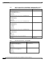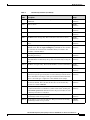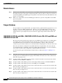
1
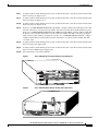
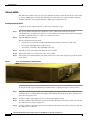
FIPS 140-2 Non-Proprietary Security Policy for
the Cisco 7206 VXR NPE-G1, Cisco 7206 VXR
NPE-G2, Cisco 7206 VXR NPE-G1 with VSA, and
the Cisco 7301 with VAM2+
Cisco 7206 VXR Chassis with NPE-G1 or NPE-G2 and VAM2+ Encryption Module
Cisco 7206 VXR Chassis with NPE-G1 or NPE-G2, VAM2+ Encryption Module and 7200 Port Adapter Jacketcard
Cisco 7206 VXR Chassis with NPE-G1 or NPE-G2 and VSA Encryption Module
Cisco 7301 Chassis with NPE-G1 and VAM2+ Encryption Module
Level 2 Validation
Document Version: Version 1.6
November 16, 2007
Introduction
This is a non-proprietary Cryptographic Module Security Policy for the 7206VXR NPE-G1, 7206VXR
NPE-G2 and 7301 with VAM+, and 7206VXR NPE-G2 with VSA from Cisco Systems, Inc., referred to
in this document as the modules, routers, or by their specific model name. This security policy describes
how modules meet the security requirements of FIPS 140-2 and how to run the modules in a FIPS 140-2
mode of operation.
This policy was prepared as part of the FIPS 140-2 Level 2 validation of the following modules:
•
7206VXR NPE-G1 or NPE-G2 with VAM2+
•
7206VXR NPE-G1 or NPE-G2 with c7200 JC-PA and VAM2+
•
7206VXR NPE-G2 with VSA and
•
7301 with VAM2+
FIPS 140-2 (Federal Information Processing Standards Publication 140-2 — Security Requirements for
Cryptographic Modules) details the U.S. Government requirements for cryptographic modules. More
information about the FIPS 140-2 standard and validation program is available on the NIST website at
http://csrc.nist.gov/cryptval/.
Americas Headquarters:
Cisco Systems, Inc., 170 West Tasman Drive, San Jose, CA 95134-1706 USA
© 2007 Cisco Systems, Inc. All rights reserved.
This document may be freely reproduced and distributed whole and intact including this copyright notice.
Module Descriptions
References
This document deals only with operations and capabilities of the module in the technical terms of a FIPS
140-2 cryptographic module security policy. More information is available on the module from the
following sources:
•
The Cisco Systems website (http://www.cisco.com) contains information on the full line of products
from Cisco Systems.
•
The NIST Cryptographic Module Validation Program website (http://csrc.ncsl.nist.gov/cryptval/)
contains contact information for answers to technical or sales-related questions for the module.
Document Organization
The Security Policy document is one document in a complete FIPS 140-2 Submission Package. In
addition to this document, the complete Submission Package contains:
•
Vendor Evidence document
•
Finite State Machine
•
Other supporting documentation as additional references
With the exception of this Non-Proprietary Security Policy, the FIPS 140-2 Validation Documentation
is proprietary to Cisco Systems, Inc. and is releasable only under appropriate non-disclosure agreements.
For access to these documents, please contact Cisco Systems, Inc.
Module Descriptions
Cisco 7206VXR NPE-G1 and NPE-G2
Cisco 7206 VXR routers are designed to support gigabit capabilities and to improve data, voice, and
video integration in both service provider and enterprise environments. Cisco 7206 VXR routers support
a high-speed network processing engines like NPE-G1, NPE-G2 and all other available network
processing engines.
Cisco 7206 VXR routers accommodate a variety of network interface port adapters and an Input/Output
(I/O) controller. A Cisco 7206 VXR router equipped with an NPE-G1 or NPE-G2 can support up to six
high-speed port adapters and can also support higher-speed port adapter interfaces including Gigabit
Ethernet and OC-12 ATM (Optical Carrier-12 Asynchronous Transfer Mode). In addition, a Cisco
7206VXR router with an NPE-G2 provides integrated I/O functionality. Cisco 7206 VXR routers also
contain bays for up to two AC-input or DC-input power supplies.
Cisco 7206 VXR routers support the following features:
•
Online insertion and removal (OIR)—Add, replace, or remove port adapters without interrupting the
system.
•
Dual hot-swappable, load-sharing power supplies—Provide system power redundancy; if one power
supply or power source fails, the other power supply maintains system power without interruption.
Also, when one power supply is powered off and removed from the router, the second power supply
immediately takes over the router power requirements without interrupting normal operation of the
router.
FIPS 140-2 Non-Proprietary Security Policy for the Cisco 7206 VXR Chassis and the Cisco 7301 Chassis
2
OL-15484-01
Module Descriptions
•
Environmental monitoring and reporting functions—Maintain normal system operation by resolving
adverse environmental conditions prior to loss of operation.
•
Downloadable software—Load new images into Flash memory remotely, without having to
physically access the router. This capability is not permitted in FIPS mode of operations, however.
Cisco 7301
The Cisco 7300 Series is optimized for flexible, feature rich IP/MPLS services at the customer network
edge, where service providers and enterprises link together. The Cisco 7300 Series can be used for
enterprise campus or Internet gateway applications or be deployed by service providers as a high-end
CPE router for managed service offerings. Other applications for the Cisco 7301 include: service
provider broadband aggregation and metro Ethernet CPE applications.
The compact Cisco 7301 router is the industry's highest performance single rack unit router with million
packets per second processing. With 3 built-in Gigabit Ethernet interfaces (copper or optical) and a
single slot for any Cisco 7000 Series port adapter the Cisco 7301 is highly flexible for a variety of
applications. Additionally for broadband aggregation, the Cisco 7301 supports up to 16,000 subscribers
sessions making it ideal for pay-as-you-grow broadband deployment models.
Cisco 7200 series Port Adapter Jacket Card (c7200-JC-PA)
The Cisco 7200 VXR Series Port Adapter Jacket Card is plugged into the I/O card slot of the 7206VXR
router. This addresses the demand on the Cisco 7206VXR router for additional slot density and
flexibility by enabling the I/O slot to hold a single port or service adapter for additional capacity on
Cisco 7206VXR systems with the NPE-G1 or NPE-G2.
The Cisco 7200 VXR Series Port Adapter Jacket Card offers the following:
•
Provides one additional slot for single port or service adapter.
•
Allows a high-bandwidth port adapter-such as the Cisco VPN Acceleration Module 2+ (VAM2+) to
be moved onto a dedicated PCI bus that Cisco NPE-G1 or NPE-G2 provides.
•
Reduces PCI contention among other port adapters.
•
Provides a cost-effective way to increase the slot density in parallel to the increased switching
capacity of Cisco NPE-G2.
Cisco VPN Acceleration Module 2 PLUS (VAM2+)
The Cisco 7206VXR NPE-G1 or NPE-G2 and 7301 routers incorporate the VPN Acceleration Module
2+ (VAM2+) cryptographic accelerator card. The VAM2+ is a single-width acceleration module that
provides high-performance, hardware-assisted tunneling and encryption services suitable for virtual
private network (VPN) remote access, site-to-site intranet, and extranet applications and is installed in
an available port adapter slot. It also provides platform scalability and security while working with all
services necessary for successful VPN deployments—security, quality of service (QoS), firewall and
intrusion detection, and service-level validation and management. The VAM2+ off-loads IPSec
processing from the main processor, thus freeing resources on the processor engines for other tasks.
FIPS 140-2 Non-Proprietary Security Policy for the Cisco 7206 VXR Chassis and the Cisco 7301 Chassis
OL-15484-01
3
Module Descriptions
Cisco VPN Services Adapter (VSA)
The Cisco 7206VXR NPE-G2 routers incorporate the VPN Services Adapter (VSA) cryptographic
accelerator card that fits into the I/O controller slot of the 7206VXR. The VSA features hardware
acceleration for various cryptographic algorithms, providing increased performance for site-to-site and
remote-access IPSec VPN services. The Cisco VSA supports full Layer 3 routing, quality of service
(QoS), multicast and multiprotocol traffic, and broad support of integrated LAN/WAN media. The VSA
off-loads IPSec processing from the main processor, thus freeing resources on the processor engines for
other tasks.
The evaluated platform consists of the following:
•
7206VXR Hardware Version – 2.9
•
7301VXR Hardware Version - 2.0
•
NPE-G1 Hardware Version – 2.1
•
NPE-G2 Hardware Version – 1.0
•
C7200-JC-PA Hardware Version – 1.0
•
VAM2+ Hardware Version – 1.0
•
VSA Hardware Version - 1.0
Module Validation Level
The following table lists the level of validation for each area in the FIPS PUB 140-2.
Table 1
Validation Level by Section
No.
Area Title
Level
1
Cryptographic Module Specification
2
2
Cryptographic Module Ports and Interfaces
2
3
Roles, Services, and Authentication
2
4
Finite State Model
2
5
Physical Security
2
6
Operational Environment
N/A
7
Cryptographic Key management
2
8
Electromagnetic Interface/Electromagnetic Compatibility
2
9
Self-Tests
2
10
Design Assurance
2
11
Mitigation of Other Attacks
N/A
The Cryptographic Module
The cryptographic boundary for the 7206VXR NPE-G1 or NPE-G2 with VAM2+ is defined as
encompassing the "top," "front," "left," "right," and "bottom" surfaces of the case; all portions of the
"backplane" of the case which are not designed to accommodate a removable port adapter; and the
FIPS 140-2 Non-Proprietary Security Policy for the Cisco 7206 VXR Chassis and the Cisco 7301 Chassis
4
OL-15484-01
Module Descriptions
inverse of the three-dimensional space within the case that would be occupied by an installed port
adapter. The cryptographic boundary includes the connection apparatus between the port adapter and the
motherboard/daughterboard that hosts the port adapter, but the boundary does not include the port
adapter itself (except when a VAM2+ is inserted into an available port adapter slot). In other words, the
cryptographic boundary encompasses all hardware components within the case of the device except any
installed modular port adapter (except when a VAM2+ is inserted into an available port adapter
interface).
The cryptographic boundary for the 7206VXR NPE-G1 or NPE-G2 with c7200-JC-PA and VAM2+ is
defined as encompassing the "top," "front," "left," "right," and "bottom" surfaces of the case; all portions
of the "backplane" of the case which are not designed to accommodate a removable port adapter; and the
inverse of the three-dimensional space within the case that would be occupied by an installed port
adapter. The cryptographic boundary includes the connection apparatus between the port adapter and the
motherboard/daughterboard that hosts the port adapter, but the boundary does not include the port
adapter itself (except when a VAM2+ is inserted into the port adapter jacket card in the I/O controller
slot). In other words, the cryptographic boundary encompasses all hardware components within the case
of the device except any installed modular port adapter (except when a VAM2+ is inserted into the port
adapter jacket card interface in the I/O controller slot). The 7206VXR can support single and dual
VAM2+ modules in FIPS mode of operation.
The cryptographic boundary for the 7301 with VAM2+ is the module case. The 7301 has one port adapter
slot, which is populated with the VAM2+.
All of the functionality discussed in this document is provided by components within this cryptographic
boundary. Each module is a multi-chip standalone module.
The cryptographic boundary for the 7206VXR NPE-G2 with VSA is defined as encompassing the "top,"
"front," "left," "right," and "bottom" surfaces of the case; all portions of the "backplane" of the case
which are not designed to accommodate a removable port adapter; the inverse of the three-dimensional
space within the case that would be occupied by an installed port adapter and the VSA installed into the
I/O controller slot. The cryptographic boundary includes VSA installed into the I/O controller slot and
the connection apparatus between the port adapter and the motherboard/daughterboard that hosts the port
adapter, but the boundary does not include the port adapter itself. In other words, the cryptographic
boundary encompasses all hardware components within the case of the device except any installed
modular port adapter.
Module Interfaces
Each module provides a number of physical and logical interfaces to the device, and the physical
interfaces provided by the module are mapped to four FIPS 140-2 defined logical interfaces: data input,
data output, control input, and status output. The logical interfaces and their mapping are described in
the following tables:
FIPS 140-2 Non-Proprietary Security Policy for the Cisco 7206 VXR Chassis and the Cisco 7301 Chassis
OL-15484-01
5
Module Descriptions
Table 2
FIPS 140-2 Logical Interfaces –7206VXR NPE-G1 or NPE-G2 with VAM2+, 7206VXR
NPE-G1 or NPE-G2 with c7200JC-PA and VAM2+, 7206VXR NPE-G2 with VSA
Router Physical Interface
FIPS 140-2 Logical Interface
10/100/1000 RJ-45 Port
SFP Gigabit Ethernet Port
Port Adapter/Mid plane Interface
Console Port
Auxiliary Port
10/100 Management Port (Not present in 7206VXR NPE-G1)
Data Input Interface
10/100/1000 BASE-TX LAN Port
Gigabit Ethernet Port
Port Adapter Interface
Console Port
Auxiliary Port
10/100 Management Port (Not present in 7206VXR NPE-G1)
Data Output Interface
10/100/1000 BASE-TX LAN Port
Gigabit Ethernet Port
Port Adapter Interface
Power Switch
Reset Switch
Console Port
Auxiliary Port
10/100 Management Port (Not present in 7206VXR NPE-G1)
Control Input Interface
10/100/1000 BASE-TX LAN Port
Port Adapter Interface
Gigabit Ethernet Port
LEDs
Console Port
Auxiliary Port
10/100 Management Port (Not present in NPE-G1)
Status Output Interface
Power Plug
Power Interface
Table 3
FIPS 140-2 Logical Interfaces – 7301 with VAM2+
Router Physical Interface
FIPS 140-2 Logical Interface
Gigabit Ethernet 0-2 RJ-45 Ports
Gigabit Ethernet 0-2 SFP GBIC Ports
Alarm Port
Console Port
Auxiliary Port
Data Input Interface
Gigabit Ethernet 0-2 RJ-45 Ports
Gigabit Ethernet 0-2 SFP GBIC Ports
Alarm Port
Console Port
Auxiliary Port
Data Output Interface
FIPS 140-2 Non-Proprietary Security Policy for the Cisco 7206 VXR Chassis and the Cisco 7301 Chassis
6
OL-15484-01
Module Descriptions
Table 3
FIPS 140-2 Logical Interfaces – 7301 with VAM2+ (continued)
Router Physical Interface
FIPS 140-2 Logical Interface
Gigabit Ethernet 0-2 RJ-45 Ports
Gigabit Ethernet 0-2 SFP GBIC Port
Alarm Port
Console Port
Auxiliary Port
Control Input Interface
Gigabit Ethernet 0-2 RJ-45 Ports
Gigabit Ethernet 0-2 SFP GBIC Ports
Alarm Port
Console Port
Auxiliary Port
LEDs
Status Output Interface
Power Plug
Power Interface
Roles, Services, and Authentication
Authentication is role-based. There are two main roles in the router that operators may assume: the
Crypto Officer role and the User role. The administrator of the router assumes the Crypto Officer role
in order to configure and maintain the router using Crypto Officer services, while the Users exercise only
the basic User services. The module supports RADIUS and TACACS+ for authentication. A complete
description of all the management and configuration capabilities of the modules can be found in the
Performing Basic System Management manual and in the online help for the modules.
The User and Crypto Officer passwords and the RADIUS/TACACS+ shared secrets must each be at least
8 characters long, including at least one letter and at least one number character, in length. See the
Secure Operation section for more information. If 6 integers, one special character and one alphabet are
used without repetition for an 8 digit PIN, the probability of randomly guessing the correct sequence is
1 in 832,000,000. In order to successfully guess the sequence in one minute would require the ability to
make over 13,000,000 guesses per second, which far exceeds the operational capabilities of the module.
Including the rest of the alphanumeric characters drastically decreases the odds of guessing the correct
sequence.”
User Services
A User enters the system by accessing the console/auxiliary port with a terminal program or via IPSec
protected Telnet or SSH v2 session to a LAN port. The IOS prompts the User for their password. If the
password is correct, the User is allowed entry to the IOS executive program. The services available to
the User role consist of the following:
•
Status Functions—View state of interfaces and protocols, version of IOS currently running
•
Network Functions—Connect to other network devices through outgoing telnet, PPP, etc. and
initiate diagnostic network services (i.e., ping, mtrace)
•
Terminal Functions—Adjust the terminal session (e.g., lock the terminal, adjust flow control)
•
Directory Services—Display directory of files kept in flash memory
FIPS 140-2 Non-Proprietary Security Policy for the Cisco 7206 VXR Chassis and the Cisco 7301 Chassis
OL-15484-01
7
Module Descriptions
Crypto Officer Services
A Crypto Officer enters the system by accessing the console/auxiliary port with a terminal program or
via IPSec protected telnet or SSH v2 session to a LAN port. The Crypto Officer authenticates as a User
and then authenticates as the Crypto Officer role.. During initial configuration of the router, the Crypto
Officer password (the “enable” password) is defined. A Crypto Officer may assign permission to access
the Crypto Officer role to additional accounts, thereby creating additional Crypto Officers.
The Crypto Officer role is responsible for the configuration and maintenance of the router. The Crypto
Officer services consist of the following:
•
Configure the Router—Define network interfaces and settings, create command aliases, set the
protocols the router will support, enable interfaces and network services, set system date and time,
and load authentication information.
•
Define Rules and Filters—Create packet Filters that are applied to User data streams on each
interface. Each Filter consists of a set of Rules, which define a set of packets to permit or deny based
characteristics such as protocol ID, addresses, ports, TCP connection establishment, or packet
direction.
•
Status Functions—View the router configuration, routing tables, active sessions, use get commands
to view SNMP MIB statistics, health, temperature, memory status, voltage, packet statistics, review
accounting logs, and view physical interface status.
•
Manage the Router—Log off users, shutdown or reload the router, manually back up router
configurations, view complete configurations, manager user rights, and restore router
configurations.
•
Set Encryption/Bypass—Set up the configuration tables for IP tunneling. Set keys and algorithms
to be used for each IP range or allow plaintext packets to be set from specified IP address.
•
Change Port Adapters—Insert and remove adapters in a port adapter slot.
•
Change VSA—Insert and remove VSA in an I/O Controller slot. (This service available only for
7206VXR NPE-G2 with VSA)
Cryptographic Key Management
The router securely administers both cryptographic keys and other critical security parameters such as
passwords. The tamper evidence seals provide physical protection for all keys. All keys are also
protected by the password-protection on the Crypto Officer role login, and can be zeroized by the Crypto
Officer. All zeroization consists of overwriting the memory that stored the key. Keys are exchanged and
entered electronically or via Internet Key Exchange (IKE).
The module supports the following critical security parameters (CSPs):
Table 4
CSP
Name
Critical Security Parameters
Description
Storage
CSP 1
This is the seed key for X9.31 PRNG. This key is stored in DRAM and DRAM
updated periodically after the generation of 400 bytes; hence, it is
(plaintext)
zeroized periodically. Also, the operator can turn off the router to
zeroize this key.
CSP 2
The public and private exponents used in Diffie-Hellman (DH)
exchange. Zeroized after DH shared secret has been generated.
DRAM
(plaintext)
FIPS 140-2 Non-Proprietary Security Policy for the Cisco 7206 VXR Chassis and the Cisco 7301 Chassis
8
OL-15484-01
Module Descriptions
Table 4
CSP
Name
Critical Security Parameters (continued)
Description
Storage
CSP 3
The shared secret within IKE exchange. Zeroized when IKE session is DRAM
terminated.
(plaintext)
CSP 4
Same as above
DRAM
(plaintext)
CSP 5
Same as above
DRAM
(plaintext)
CSP 6
Same as above
DRAM
(plaintext)
CSP 7
The IKE session encrypt key. The zeroization is the same as above.
DRAM
(plaintext)
CSP 8
The IKE session authentication key. The zeroization is the same as
above.
DRAM
(plaintext)
CSP 9
The key used to generate IKE skeyid during preshared-key
NVRAM
authentication. The no crypto isakmp key command zeroizes it. This (plaintext)
key can have two forms based on whether the key is related to the
hostname or the IP address.
CSP 10 This key generates keys 3, 4, 5 and 6. This key is zeroized after
generating those keys.
DRAM
(plaintext)
CSP 11 The fixed key used in Cisco vendor ID generation. This key is
NVRAM
embedded in the module binary image and can be deleted by erasing the (plaintext)
Flash.
CSP 12 The IPSec encryption key. Zeroized when IPSec session is terminated. DRAM
(plaintext)
CSP 13 The IPSec authentication key. The zeroization is the same as above.
DRAM
(plaintext)
CSP 14 This key is used by the router to authenticate itself to the peer. The
DRAM
router itself gets the password (that is used as this key) from the AAA (plaintext)
server and sends it onto the peer. The password retrieved from the AAA
server is zeroized upon completion of the authentication attempt.
CSP 15 The authentication key used in PPP. This key is in the DRAM and not
zeroized at runtime. One can turn off the router to zeroize this key
because it is stored in DRAM.
DRAM
(plaintext)
CSP 16 This key is used by the router to authenticate itself to the peer. The key NVRAM
is retrieved from the local database (on the router itself). Issuing the (plaintext)
no username password command zeroizes the password (that is used
as this key) from the local database.
CSP 17 The password of the User role. This password is zeroized by
overwriting it with a new password.
NVRAM
(plaintext)
CSP 18 The plaintext password of the CO role. This password is zeroized by
overwriting it with a new password.
NVRAM
(plaintext)
FIPS 140-2 Non-Proprietary Security Policy for the Cisco 7206 VXR Chassis and the Cisco 7301 Chassis
OL-15484-01
9
Module Descriptions
Table 4
CSP
Name
Critical Security Parameters (continued)
Description
Storage
CSP 19 The ciphertext password of the CO role. However, the algorithm used NVRAM
to encrypt this password is not FIPS approved. Therefore, this password (plaintext)
is considered plaintext for FIPS purposes. This password is zeroized by
overwriting it with a new password.
CSP 20 The RADIUS shared secret. This shared secret is zeroized by executing NVRAM
the “no” form of the RADIUS shared secret set command.
(plaintext), DRAM
(plaintext)
CSP 21 The TACACS+ shared secret. This shared secret is zeroized by
executing the “no” form of the RADIUS shared secret set command.
NVRAM
(plaintext), DRAM
(plaintext)
CSP 22 The SSH session key. It is zeroized automatically when the SSH
session is terminated.
DRAM (plaintext)
CSP 231 The keys and CSPs above from no. 1 to 21 are located in the router
DRAM of VAM2+
outside VAM2+ or VSA. However, the ByteArray key object is located (plaintext)
in the RAM of the VAM2+. All key objects of the VAM2+ are built
upon the ByteArray key object. The destructor of the ByteArray object
uses memset function to overwrite all bytes of the object to 0x00.
1.
This key not present in 7206VXR NPE-G2 with VSA.
The services accessing the CSPs, the type of access and which role accesses the CSPs are listed in
Table 5. The module supports IOS implementations of Triple-DES, DES-MAC, Triple-DES-MAC, AES,
SHA-1, HMAC SHA-1, MD5, HMAC MD5, Diffie-Hellman, RNG and RSA cryptographic algorithms.
Except for SHA-1 and RNG none of the other software algorithm implementations are used when
operating in FIPS mode. IOS implementation of Diffie-Hellman is used in all module configurations
except 7206VXR NPE-G2 with VSA which uses hardware implementation of DH.
Note
Pursuant to the DES Transition Plan and the approval of the Withdrawal of Federal Information
Processing Standard (FIPS) 46-3, Data Encryption Standard (DES); FIPS 74, Guidelines for
Implementing and Using the NBS Data Encryption Standard; and FIPS 81, DES Modes of Operation,
the DES algorithm shall not be used in FIPS approved mode of operation.
FIPS 140-2 Non-Proprietary Security Policy for the Cisco 7206 VXR Chassis and the Cisco 7301 Chassis
10
OL-15484-01
OL-15484-01
CSP 23
CSP 22
CSP 21
CSP 20
CSP 19
CSP 18
CSP 17
CSP 16
CSP 15
CSP 14
CSP 13
CSP 12
CSP 11
CSP 10
CSP 8
CSP 8
CSP 7
CSP 6
CSP 5
CSP 4
CSP 3
CSP 2
Role/Service
User role
Status Functions
Network Functions
r
r
r
r
r
r
r
r
r
r
r
r
r
r
r
r
r
Terminal Functions
Directory Services
Crypto-Officer Role
rw
d
Configure the Router
rw
d
Define Rules and Filters
Status Functions
d
rw d
d
Manage the Router
Set Encryption/Bypass
rw rw rw rw rw rw rw rw rw rw
d d d d d d d d d d
rw rw
d d
rw rw rw rw rw rw rw
d d d d d d d
rw
Change Port Adapters
Change VSA
11
Module Descriptions
FIPS 140-2 Non-Proprietary Security Policy for the Cisco 7206 VXR Chassis and the Cisco 7301 Chassis
SRDI/Role/Service Access
Policy
CSP 1
Role and Service Access to CSPs
Security Relevant
Data Item
Table 5
Module Descriptions
Each cryptographic implementation has achieved the following validations:
Algorithm Certificates
Table 6
Algorithm
IOS (NPE-G1)
IOS (NPE-G2)
VAM2+
VSA
AES
Not supported in
FIPS mode
Not supported in
FIPS mode
173
91
Triple-DES
Not supported in
FIPS mode
Not supported in
FIPS mode
275
204
SHA-1
557
556
258
500
HMAC SHA-1
Not supported in
FIPS mode
Not supported in
FIPS mode
39
203
RNG
267
266
83
-
RSA
Not supported in
FIPS mode
Not supported in
FIPS mode
Not supported in
FIPS mode
Not supported in
FIPS mode
The module supports the following key management schemes:
•
Pre-shared key exchange via electronic key entry. Triple-DES/AES key and HMAC-SHA-1 key are
exchanged and entered electronically.
•
Internet Key Exchange method with support for pre-shared keys exchanged and entered
electronically.
– The pre-shared keys are used with Diffie-Hellman key agreement technique to derive DES,
Triple-DES or AES keys.
– The pre-shared key is also used to derive HMAC-SHA-1 key.
The Diffie-Hellman key establishment methodology provides 80 or 96 bits of encryption strength.
All pre-shared keys are associated with the CO role that created the keys, and the CO role is protected
by a password. Therefore, the CO password is associated with all the pre-shared keys. The Crypto
Officer needs to be authenticated to store keys. All Diffie-Hellman (DH) keys agreed upon for individual
tunnels are directly associated with that specific tunnel only via the IKE protocol. All of the keys and
CSPs of the module can be zeroized. Please refer to Figure 4 for information on methods to zeroize each
key and CSP.
Self-Tests
The modules include an array of self-tests that are run during startup and periodically during operations
to prevent any secure data from being released and to insure all components are functioning correctly.
The modules implement the following power-on self-tests:
FIPS 140-2 Non-Proprietary Security Policy for the Cisco 7206 VXR Chassis and the Cisco 7301 Chassis
12
OL-15484-01
Secure Operation
Table 7
Module Power On Self Tests
Implementation
Tests Performed
IOS
Software/firmware test
Bypass test
SHA-1 KAT
PRNG KAT
DH Test1
VAM2+
Firmware integrity test
Triple-DES KAT
AES KAT
SHA-1 KAT
HMAC-SHA-1 KAT
PRNG KAT
VSA
Firmware integrity test
Triple-DES KAT
AES KAT
SHA-1 KAT
HMAC-SHA-1 KAT
DH Test
1.
IOS implementation of DH is not used in 7206VXR NPE-G2 with VSA.
The modules perform all power-on self-tests automatically at boot. All power-on self-tests must be
passed before any operator can perform cryptographic services. The power-on self-tests are performed
after the cryptographic systems are initialized but prior to the initialization of the LANs; this prevents
the module from passing any data during a power-on self-test failure.
In addition, the module also provides the following conditional self-tests:
Table 8
Module Conditional Self Tests
Implementation
IOS
VAM2+
VSA
Tests Performed
•
Continuous Random Number Generator test for the FIPS-approved RNG
•
Continuous Random Number Generator test for the non-approved RNGs
•
Conditional Bypass test
•
Continuous Random Number Generator test for the FIPS-approved RNG
•
Continuous Random Number Generator test for the non-approved RNGs
•
Continuous Random Number Generator test for the non-approved RNG
Secure Operation
These routers meet all the applicable Level 2 requirements for FIPS 140-2. Follow the setting
instructions provided below to place the module in FIPS mode. Operating this router without
maintaining the following settings will remove the module from the FIPS approved mode of operation.
All configuration activities must be performed via the command line interface via the console (for initial
configuration) or IPSec protected SSH v2 or telnet sessions – neither the web configuration tools CSRW
or SDM may be used.
FIPS 140-2 Non-Proprietary Security Policy for the Cisco 7206 VXR Chassis and the Cisco 7301 Chassis
OL-15484-01
13
Secure Operation
System Initialization and Configuration
Step 1
Step 2
The Crypto Officer must perform the initial configuration. The following advanced enterprise builds are
the only allowable images; no other image may be loaded.
•
7206VXR NPE-G1 or NPE-G2 with VAM2+; 7206VXR NPE-G2 with VSA:
c7200-adventerprisek9-mz.124-11.T1 (IOS version 12.4(11)T1)
•
7206VXR NPE-G1 or NPE-G2 with c7200-JC-PA and VAM2+: c7200-adventerprisek9p-mz (IOS
version 12.4(11)T1)
•
7301 with VAM2+: c7301-adventerprisek9-mz.124-11.T (IOS version 12.4(11)T1)
The value of the boot field must be 0x0102. This setting disables break from the console to the ROM
monitor and automatically boots the IOS image. From the “configure terminal” command line, the
Crypto Officer enters the following syntax:
config-register 0x0102
Step 3
The Crypto Officer must enter the following command to prevent failover to software implementation:
no crypto engine software ipsec
Step 4
The Crypto Officer must create the “enable” password for the Crypto Officer role. The password must
be at least 8 characters, including at least one letter and at least one number, and is entered when the
Crypto Officer first engages the “enable” command. The Crypto Officer enters the following syntax at
the “#” prompt:
enable secret [PASSWORD]
Step 5
The Crypto Officer must always assign passwords (of at least 8 characters, including at least one letter
and at least one number) to users. Identification and authentication on the console/auxiliary port is
required for Users. From the “configure terminal” command line, the Crypto Officer enters the following
syntax:
line con 0
password [PASSWORD]
login local
Step 6
The Crypto Officer shall not assign users to privilege level other than Level 1 (the default).
Step 7
The Crypto Officer may configure the module to use RADIUS or TACACS+ for authentication.
Configuring the module to use RADIUS or TACACS+ for authentication is optional. If the module is
configured to use RADIUS or TACACS+, the Crypto-Officer must define RADIUS or TACACS+ shared
secret keys that are at least 8 characters long, including at least one letter and at least one number.
Step 8
The Crypto Officer must apply tamper evidence labels as described later in this document.
Step 9
The module must be configured to only use hardware acceleration. As such if there is a failure in the
VAM2+ or VSA card, the module is considered to be out of FIPS-Approved Mode of operation.
•
A failure in the integrity check for VAM2+ will be indicated via the following console message:
<DATE>: %VPN_HW-1-INITFAIL: Slot <SLOT NUMBER>: File doesn't verify
<DATE>: %VPN_HW-1-INITFAIL: Slot <SLOT NUMBER>: microcode download
failure
The status of the VAM2+ can also be verified with the show crypto engine config command.
•
A failure in the integrity check for VSA will be indicated via the following console message:
FIPS 140-2 Non-Proprietary Security Policy for the Cisco 7206 VXR Chassis and the Cisco 7301 Chassis
14
OL-15484-01
Secure Operation
VSA boot error: POST FAILURE
The status of the VSA can also be verified with the show crypto engine accelerator statistic and
show crypto eli commands.
Note
The keys and CSPs generated in the cryptographic module during FIPS mode of operation
cannot be used when the module transitions to non-FIPS mode and vice versa. While the module
transitions from FIPS to non-FIPS mode or from non-FIPS to FIPS mode, all the keys and CSPs
are to be zeroized by the Crypto Officer.
Note
For an overview of the VAM2+ and c7200-JC-PA LEDs, please refer to the Installation and
Configuration Guide at the following URL:
http://www.cisco.com/en/US/products/hw/modules/ps2033/products_installation_and_configur
ation_guide_chapter09186a0080369590.html#wp1038368
IPSec Requirements and Cryptographic Algorithms
Step 1
The only type of key management that is allowed in FIPS mode is Internet Key Exchange (IKE).
Step 2
Although the IOS implementation of IKE allows a number of algorithms, only the following algorithms
are allowed in a FIPS 140-2 configuration:
Step 3
•
ah-sha-hmac
•
esp-sha-hmac
•
esp-3des
•
esp-aes
The following algorithms shall not be used:
•
MD-5 for signing
•
MD-5 HMAC
•
DES
•
Software implementations of AES, DES, Triple-DES, SHA-1 HMAC, and RSA
Protocols
Step 1
SNMP v3 over a secure IPSec tunnel may be employed for authenticated, secure SNMP gets and sets.
Since SNMP v2C uses community strings for authentication, only gets are allowed under SNMP v2C.
Step 2
Secure DNS is not allowed in FIPS mode of operation and shall not be configured.
FIPS 140-2 Non-Proprietary Security Policy for the Cisco 7206 VXR Chassis and the Cisco 7301 Chassis
OL-15484-01
15
Secure Operation
Remote Access
Step 1
Telnet access to the module is only allowed via a secure IPSec tunnel between the remote system and
the module. The Crypto officer must configure the module so that any remote connections via telnet are
secured through IPSec, using FIPS-approved algorithms. Note that all users must still authenticate after
remote access is granted.
Step 2
SSH access to the module is allowed in FIPS approved mode of operation, using SSH v2 and a FIPS
approved algorithm.
Tamper Evidence
Any port adapter slot not populated with a port adapter must be populated with an appropriate slot cover
in order to operate in a FIPS compliant mode. The slot covers are included with each router, and
additional covers may be ordered from Cisco. The same procedure mentioned below to apply tamper
evidence labels for port adapters must also be followed to apply tamper evidence labels for the slot
covers.
7206VXR NPE-G1/ NPE-G2 with VAM2+, 7206VXR NPE-G1/NPE-G2 with c7200-JC-PA and VAM2+ and
7206VXR NPE-G2 with VSA
The front of the router provides 6 port adapter slots (An additional port adapter slot is available when a
port adapter jacket card is inserted into the I/O controller slot), and the rear of the router provides
on-board LAN connectors, PC Card slots, and Console/Auxiliary connectors. The power cable
connection, a power switch, and the access to the Network Processing Engine are at the rear of the router.
Once the router has been configured to meet FIPS 140-2 Level 2 requirements, the router cannot be
accessed without signs of tampering. The Crypto Officer shall be instructed to record serial numbers,
and to inspect for these signs of tampering or changed numbers periodically.
To seal the system, apply serialized tamper-evidence labels as depicted in Figure 1 and Figure 2 as
follows:
Step 1
Clean the cover of any grease, dirt, or oil before applying the tamper evidence labels. Alcohol-based
cleaning pads are recommended for this purpose. The ambient air must be above 10°C, otherwise the
labels may not properly cure.
Step 2
A tamper evidence label shall be placed so that the one half of the label covers the enclosure and the
other half covers the NPE-G1 or NPE-G2.
Step 3
A tamper evidence label shall be placed over the Compact Flash card slot on the NPE-G1/NPE-G2.
Step 4
A tamper evidence label shall be placed over the USB ports of the NPEG2.
Step 5
A tamper evidence label shall be placed so that one half of the label covers the enclosure and the other
half covers the port adapter slot 1.
Step 6
A tamper evidence label shall be placed so that one half of the label covers the enclosure and the other
half covers the port adapter slot 2.
Step 7
A tamper evidence label shall be placed so that one half of the label covers the enclosure and the other
half covers the port adapter slot 3.
FIPS 140-2 Non-Proprietary Security Policy for the Cisco 7206 VXR Chassis and the Cisco 7301 Chassis
16
OL-15484-01
Secure Operation
Step 8
A tamper evidence label shall be placed so that one half of the label covers the enclosure and the other
half covers the port adapter slot 4.
Step 9
A tamper evidence label shall be placed so that one half of the label covers the enclosure and the other
half covers the port adapter slot 5.
Step 10
A tamper evidence label shall be placed so that one half of the label covers the enclosure and the other
half covers the port adapter slot 6.
Step 11
In the case of 7206VXR NPE-G1/NPE-G2 with VAM2+, a tamper evidence label shall be placed so that
one half of the label covers the enclosure and the other half covers the I/O Controller blank face plate.
In the case of 7206VXR NPE-G1/NPE-G2 with c7200-JC-PA and VAM2+ a tamper evidence label shall
be placed so that one half of the label covers the enclosure and the other half covers the port adapter
jacket card face plate and the port adapter slot. In the case of 7206VXR NPE-G2 with VSA, a tamper
evidence label shall be placed such that one half of the label covers the enclosure and the other half
covers the VSA.
Step 12
A tamper evidence label shall be placed so that one half of the label covers the enclosure and the other
half covers the power supply plate.
Step 13
A tamper evidence label shall be placed so that one half of the label covers the enclosure and the other
half covers the redundant power supply plate.
Step 14
Allow the labels to cure for five minutes.
Figure 1
Cisco 7206VXR (Front) Tamper Evident Label Placement
3
2
1
0
6
TOKEN RING
5
FAST ETHERNET
4
RJ4
5
MII
0
LIN
K
D
LE
AB
EN
2
TX
RX
PC
M
C
IA
0
119799
1
Cisco 7200
Series VXR
4
TX
RX
3
TX
RX
2
TX
RX
1
TX
EN
ETHERNET-10BFL
0
CD
LB
RC
RD
TC
TD
CD
LB
RC
RD
TC
TD
CD
LB
RC
RD
TC
TD
CD
LB
RC
RD
TC
TD
EN
FAST SERIAL
RX
3
3
2
2
1
0
LINK
1
0
3
EN
AB
LE
D
ETHERNET 10BT
Cisco 7206VXR (Back) Tamper Evident Label Placement
119798
Figure 2
NETWORK PROCESSING ENGINE-300
FIPS 140-2 Non-Proprietary Security Policy for the Cisco 7206 VXR Chassis and the Cisco 7301 Chassis
OL-15484-01
17
Secure Operation
7301 with VAM2+
The 7301 router requires that a special opacity shield be installed over the intake-side air vents in order
to operate in FIPS-approved mode. The shield decreases the surface area of the vent holes, reducing
visibility within the cryptographic boundary to FIPS-approved specifications.
Installing the Opacity Shield:
To install an opacity shield on the Cisco 7301 router, follow these steps:
Step 1
The opacity shield is designed to be installed on a Cisco 7301 router chassis that is already
rack-mounted. If your 7301 router chassis is not rack-mounted, install the chassis in the rack using the
procedures contained in the Cisco 7301 router Installation Guide.
Step 2
Open the FIPS kit packaging.
The kit contains the following items:
Figure 3
•
A packaged opacity shield assembly with installation hardware for the Cisco 7301 router.
•
An envelope with FIPS tamper evidence labels.
•
An envelope containing a disposable ESD wrist strap.
Step 3
Open the protective packaging and remove the opacity shield.
Step 4
Remove the sticker cover on the back of the opacity shield.
Step 5
Line up the opacity shield with the rack mount screw holes on the router, and press it against the chassis
of the router.
Cisco 7301 with Opacity Shield Installed
To seal the system, apply serialized tamper-evidence labels as depicted in Figure 4 and as follows:
Step 1
Clean the cover of any grease, dirt, or oil before applying the tamper evidence labels. Alcohol-based
cleaning pads are recommended for this purpose. The ambient air must be above 10°C, otherwise the
labels may not properly cure.
Step 2
A tamper evidence label shall be placed over the Compact Flash card slot.
Step 3
A tamper evidence label shall be placed so that one half of the label covers the top of the enclosure and
the other half covers the port adapter slot.
Step 4
A tamper evidence label shall be placed so that one half of the label covers the top of the enclosure and
the other half covers the side.
FIPS 140-2 Non-Proprietary Security Policy for the Cisco 7206 VXR Chassis and the Cisco 7301 Chassis
18
OL-15484-01
Definition List
Step 5
A tamper evidence label shall be placed over each of the four corners of the opacity shield.
Step 6
Allow the labels to cure for five minutes.
Figure 4
Cisco 7301 (Front) Tamper Evident Label Placement
D
R
LE LS RIE M
AB EL AR AR
EN RX C RX C X AL
R
ATM
GIGABIT ETHER
NET
RJ45 EN
0/0
LINK
TX GBIC
GIGABIT ETHER
NET
RX
RJ45 EN
0/1
LINK
TX GBIC
GIGABIT ETHER
NET
RX
RJ45 EN
0/2
LINK
TX GBIC
AUX
RX
CONSOLE
ALARM
COMPACT
FLASH
100-24 0V,
2A, 50/60
Hz
24V=9 A,
48 - 60V=5
A
STATUS
A
B
CISCO 7301
186272
SLOT 1
The tamper evident seals are produced from a special thin gauge vinyl with self-adhesive backing. Any
attempt to open the device will damage the tamper evident seals or the material of the module cover.
Since the tamper evident seals have non-repeated serial numbers, they may be inspected for damage and
compared against the applied serial numbers to verify that the module has not been tampered with.
Tamper evident seals can also be inspected for signs of tampering, which include the following: curled
corners, rips, and slices.
Definition List
AAA—Authentication, Authorization and Accounting
AES—Advanced Encryption Standard
CMVP—Cryptographic Module Validation Program
CSP—Critical Security Parameter
DES—Data Encryption Standard
FIPS—Federal Information Processing Standard
HTTP—Hyper Text Transfer Protocol
KAT—Known Answer Test
LED—Light Emitting Diode
NPE—Network Processing Engine
NIST—National Institute of Standards and Technology
NVLAP—National Voluntary Laboratory Accreditation Program
PPP—Point to Point Protocol
RAM—Random Access Memory
RSA—Rivest, Shamir, and Adleman method for asymmetric encryption
SHA—Secure Hash Algorithm
VAM—VPN Acceleration Module
FIPS 140-2 Non-Proprietary Security Policy for the Cisco 7206 VXR Chassis and the Cisco 7301 Chassis
OL-15484-01
19
Obtaining Documentation, Obtaining Support, and Security Guidelines
Obtaining Documentation, Obtaining Support, and Security
Guidelines
For information on obtaining documentation, obtaining support, providing documentation feedback,
security guidelines, and also recommended aliases and general Cisco documents, see the monthly
What’s New in Cisco Product Documentation, which also lists all new and revised Cisco technical
documentation, at:
http://www.cisco.com/en/US/docs/general/whatsnew/whatsnew.html
CCVP, the Cisco logo, and Welcome to the Human Network are trademarks of Cisco Systems, Inc.; Changing the Way We Work, Live, Play, and
Learn is a service mark of Cisco Systems, Inc.; and Access Registrar, Aironet, BPX, Catalyst, CCDA, CCDP, CCIE, CCIP, CCNA, CCNP, CCSP,
Cisco, the Cisco Certified Internetwork Expert logo, Cisco IOS, Cisco Press, Cisco Systems, Cisco Systems Capital, the Cisco Systems logo,
Cisco Unity, Enterprise/Solver, EtherChannel, EtherFast, EtherSwitch, Fast Step, Follow Me Browsing, FormShare, GigaDrive, HomeLink, Internet
Quotient, IOS, iPhone, IP/TV, iQ Expertise, the iQ logo, iQ Net Readiness Scorecard, iQuick Study, LightStream, Linksys, MeetingPlace, MGX,
Networkers, Networking Academy, Network Registrar, PIX, ProConnect, ScriptShare, SMARTnet, StackWise, The Fastest Way to Increase Your
Internet Quotient, and TransPath are registered trademarks of Cisco Systems, Inc. and/or its affiliates in the United States and certain other countries.
All other trademarks mentioned in this document or Website are the property of their respective owners. The use of the word partner does not imply
a partnership relationship between Cisco and any other company. (0710R)
© 2007 Cisco Systems, Inc. All rights reserved.
FIPS 140-2 Non-Proprietary Security Policy for the Cisco 7206 VXR Chassis and the Cisco 7301 Chassis
20
OL-15484-01