1
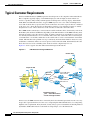
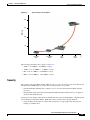
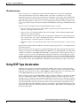
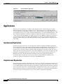
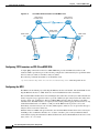
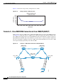
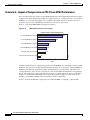
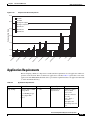
C H A P T E R
4
FCIP over IP/MPLS Core
This chapter discusses the transport of Fibre Channel over IP (FCIP) over IP/Multiprotocol Label
Switching (MPLS) networks and addresses the network requirements from a service provider (SP)
perspective. This chapter also describes service architectures and storage service offerings using FCIP
as a primary storage transport mechanism.
Overview
Storage extension solutions offer connectivity between disparate storage “islands,” and promote
transport solutions that are specifically geared towards carrying storage area network (SAN) protocols
over WAN and MAN networks. This emerging demand is providing a new opportunity for carriers. SPs
can now deliver profitable SAN extension services over their existing optical (Synchronous Optical
Network [SONET]/Synchronous Digital Hierarchy [SDH] and Dense Wavelength Division Multiplexing
[DWDM]) or IP infrastructure. DWDM networks are ideal for high-bandwidth, highly resilient networks
and are typically deployed within metro areas. Transporting storage traffic over the existing
SONET/SDH infrastructure allows SPs to maximize the use of their existing SONET/SDH ring
deployments. Some applications do not mandate stringent requirements offered by optical networks.
These applications can be easily transported over IP networks using FCIP interfaces. The obvious
advantage of transporting storage over IP is the ubiquitous nature of IP.
Disk replication is the primary type of application that runs over an extended SAN network for business
continuance or disaster recovery. The two main types of disk replication are array-based (provided by
EMC2 SRDF, Hitachi True Copy, IBM PPRC XD, or HP DRM, and host-based (for example, Veritas
Volume Replicator). Both disk replication types run in synchronous and asynchronous modes. In
synchronous mode, an acknowledgement of a host-disk write is not sent until a copy of the data to the
remote array is completed. In asynchronous mode, host-disk writes are acknowledged before the copy
of the data to the remote array is completed.
Applications that use synchronous replication are highly sensitive to response delays and might not work
with slow-speed or high-latency links. It is important to consider the network requirements carefully
when deploying FCIP in a synchronous implementation. Asynchronous deployments of FCIP are
recommended in networks with latency or congestion issues. With FCIP, Fibre Channel SAN can be
extended anywhere an IP network exists and the required bandwidth is available. FCIP can be extended
over metro, campus, or intercontinental distances using MPLS networks. FCIP may be an ideal choice
for intercontinental and coast-to-coast extension of SAN.
Data Center High Availability Clusters Design Guide
OL-12518-01
4-1
Chapter 4
FCIP over IP/MPLS Core
Typical Customer Requirements
Typical Customer Requirements
Small-to-medium businesses (SMBs) represent about 90 percent of all companies in the United States.
These companies typically employ a few hundred employees and are highly focused on their core
services or products. They usually lack IT expertise and manpower to develop, deploy, and maintain
LAN, WAN, and SAN infrastructures. A typical SMB may have one or two offices in multiple metro
areas with one head office (corporate office) in one of the metro areas. The corporate office is considered
as the home office, where the majority of the business activities occur, and other locations are usually
designated as satellite offices where most of the activities are directed to the home office.
These SMBs use IP connectivity to connect between satellite and home offices. Connectivity varies from
Frame Relay, TI, and fractional Ethernet, depending on the demand and size of the SMB. Currently, these
networks are used to carry data and voice traffic. A similar connectivity is considered for storage, but is
not currently installed because of cost constraints. Most of the data at the home office location may be
consolidated into a local SAN, and the data at the satellite offices can be consolidated into small SAN
islands. This introduces the problem of storage connectivity between SAN islands for disaster recovery
and business continuance. There are several options to interconnect the SAN, but the IP network is the
ideal choice because of its availability at the client site and its comparatively low cost.
Figure 4-1 shows a typical customer SAN extension through an SP network.
Figure 4-1
SAN Extension Through SP Network
Remote Sites
FC
Fabric
Corporate HQ
FC
Cisco7206 VXR
with FCIP PA
SprintLink
Network
Cisco MDS 9216
Multilayer Edge
Switch
FCIP
FC
Fabric
FCIP
FC
Fabric
FC
Cisco7206 VXR
with FCIP PA
FC
Bandwidth options:
DS1 – OC3 TDM Facilities
FastE and GigE Facilities
132421
FC
Fabric
In most cases, the SMB customers have connectivity that is less than DS3 speed and, in some cases, may
be up to OC-3 speeds. Therefore, in some cases, compressing the Fibre Channel data before transporting
might become a requirement. In any network, security is key to protect valuable data from being misused
by intruders. FCIP traffic must be secured before transporting it across the SP network.
Data Center High Availability Clusters Design Guide
4-2
OL-12518-01
Chapter 4
FCIP over IP/MPLS Core
Typical Customer Requirements
The requirements are as follows:
•
FCIP transport over an optimized IP/MPLS network
•
Some type of compression mechanism (software or hardware)
•
Security mechanism (IPSec, encryption, and VPN networks)
•
End-to-end management of FCIP traffic
Compression
The primary objective of compression is to reduce the amount of overall traffic on a particular WAN link.
This is achieved when a data rate equal to the WAN link speed is compressed, thereby reducing the total
amount of data on the WAN link. In this case, non-compressed storage data requires all of the 45 Mb/sec
DS3 WAN connection. By enabling compression on the storage data (assuming an average of 2 to 1
compression), the effective utilization of the WAN link by storage traffic would be 22.5 Mb/sec. This
allows the WAN link to be used by other IP traffic. The second objective for compression may be to carry
more data over a WAN link than it is normally capable of carrying. An example of this is to compress a
90-Mbps Fibre Channel data stream and carry it over a 45-Mbps WAN link (still assuming an average of
compression ratio of 2 to 1).
There are several types of compression algorithms. The most common type used in data networks is
lossless data compression (LZS). This type of compression converts the original data into a compressed
format that then can be restored into the original data. The service adapter modules (7600-SA-VAM,
SA-VAM2) and the storage services module (MDS-IPS-8 IP) use the IP Payload Compression Protocol
(IPPCP)/LZS (RFC 2395) algorithm for compressing data.
The LZS compression algorithm works by searching for redundant data strings in the input data stream
and then replaces these strings with data tokens that are shorter in length than the original data. A table
is built of these string matches, pointing to previous data in the input stream. The net result is that future
data is compressed based on previous data. The more redundant the data in the input stream, the better
the compression ratio. Conversely, the more random the data, the worse the compression ratio will be.
The compression history used by LZS is based on a sliding window of the last 2000 bytes of the input
stream. When the data is transmitted, it contains both literal data and compressed tokens. Literal data are
input data streams that cannot be compressed and are transmitted uncompressed. Compressed tokens are
pointer offsets and data length that point to the compression history table. The remote side rebuilds the
data from the compressed history table based on the pointers and length fields.
Note
A full description of IPPCP and LZS are available in RFC 2395 and in ANSI X.3241-1994.
Compression Support in Cisco MDS
Both software- and hardware-based compression are supported by the Cisco MDS product line.
Depending on the SAN-OS version and the hardware used, customers can determine which compression
methods apply.
The software-based compression solution is available on the IPS-IP Storage Service Module for the
Cisco MDS 9216/MDS 9216i fabric switch and the Cisco MDS 9500 series storage directors. This
feature is available in SAN-OS version 1.3(2a) and later releases. The software-based compression is
available on each of the eight IPS-8 Gigabit Ethernet ports. The number of Gigabit Ethernet ports used
on the IPS does not affect the performance of the compression with this feature enabled.
Data Center High Availability Clusters Design Guide
OL-12518-01
4-3
Chapter 4
FCIP over IP/MPLS Core
Typical Customer Requirements
Hardware-based compression is available with SAN-OS version 2.0 and with new hardware (MDS
9216i/MLS14/2). Compression is applied per FCIP interface (tunnel) with a variety of modes available.
Beginning with SAN-OS 2.0, three compression modes are configurable with additional support for the
MPS-14/2 module.
Compression Modes and Rate
In SAN-OS 1.3, the following two compression modes can be enabled per FCIP interface on the IPS-4
and IPS-8:
•
High throughput ratio—Compression is applied to outgoing FCIP packets on this interface with
higher throughput favored at the cost of a slightly lower compression rate.
•
High compression ratio—Compression is applied to outgoing FCIP packets on this interface with a
higher compression ratio favored at the cost of a slightly lower throughput.
In SAN-OS 2.0, three compression modes are available per FCIP interface on the IPS-4, IPS-8, and
MPS-14/2:
•
Mode 1—Equivalent to the high throughput ratio of SAN-OS 1.3. Use Mode 1 for WAN paths up to
100 Mbps on the IPS-4 and IPS-8; and WAN paths up to 1 Gbps on the MPS-14/2.
•
Mode 2—Higher compression ratio than Mode1, but applicable only to slow WAN links up to 25
Mbps.
•
Mode 3—Higher compression ratio than Mode 1 and slightly higher than Mode 2. Applicable to
very slow WAN links up to 10 Mbps.
The following are the software-based compression options for FCIP for the Cisco MDS 9000 IP Storage
Services Module:
•
SAN-OS 1.3—Two algorithms: high throughput and high compression
•
SAN-OS 2.0—Three algorithms: Modes 1–3
The following is the hardware- and software-based compression and hardware-based encryption for
FCIP for the Cisco MDS 9000 Multi-Protocol Services module:
•
SAN-OS 2.0—Three algorithms: Modes 1–3
The choice between these solutions should be based on the following factors:
Note
•
Available link speed or bandwidth
•
Choice of FCIP solution (IPS-8/4 FCIP, MPS-14/2, or PA-FC-1G port adapter)
•
New or existing SAN fabric installations
For more information, see the following: LZS (RFC 1974), IPPCP with LZS (RFC 2395), Deflate (RFC
1951), and IPPCP with Deflate (RFC 2394).
Figure 4-2 shows a comparison of the Cisco compression solutions.
Data Center High Availability Clusters Design Guide
4-4
OL-12518-01
Chapter 4
FCIP over IP/MPLS Core
Typical Customer Requirements
Figure 4-2
Cisco Compression Solutions
200
MB/sec
150
100
SA-VAM
2001
SA-VAM2
2003
IPS
2003
MPS
2004
132422
50
The following performance data applies to Figure 4-2:
•
VAM—9.9–12 MB/sec –10.9 MB/sec average
•
VAM2—19.7–25.4 MB/sec – 19 MB/sec average
•
IPS—18.6–38.5 MB/sec – 24.6 MB/sec average
•
MPS—136–192 MB/sec – 186.5 MB/sec average
Security
The security of the entire Fibre Channel fabric is only as good as the security of the entire IP network
through which an FCIP tunnel is created. The following scenarios are possible:
•
Unauthorized Fibre Channel device gaining access to resources through normal Fibre Channel
processes
•
Unauthorized agents monitoring and manipulating Fibre Channel traffic that flows over physical
media used by the IP network
Security protocols and procedures used for other IP networks can be used with FCIP to safeguard against
any known threats and vulnerabilities. FCIP links can be secured by the following methods:
•
Using the IPSec Security Protocol Suite with encryption for cryptographic data integrity and
integrity of authentication
Data Center High Availability Clusters Design Guide
OL-12518-01
4-5
Chapter 4
FCIP over IP/MPLS Core
Typical Customer Requirements
•
SPs providing VPN service to transport FCIP traffic to provide additional security
•
Using an MPLS extranet for application-specific security
Cisco Encryption Solutions
For selecting compression solutions for FCIP SAN extension, a user needs to determine the requirements
for the encryption solution. These requirements may include the speed of the link that needs encryption,
the type of encryption required, and the security requirements of the network. Cisco offers three
hardware-based encryption solutions in the data center environment. The SA-VAM and SA-VAM2
service modules for the Cisco 7200 VXR and 7400 series routers and the IPSec VPN Services Module
(VPNSM) for the Catalyst 6500 switch and the Cisco 7600 router.
Each of these solutions offers the same configuration steps, although the SA-VAM2 and IPSec VPNSM
have additional encryption options. The SA-VAM and SA-VAM2 are used only in WAN deployments,
whereas the IPSec VPNSM can support 1.6 Gb/sec throughput, making it useful in WAN, LAN, and
MAN environments.
The SA-VAM is supported on the 7100, 7200 VXR, and 7401 ASR routers with a minimum Cisco IOS
version of 12.1(9)E or 12.1(9)YE. For use in the 7200 VXR routers, the SA-VAM has a bandwidth cost
of 300 bandwidth points. The SA-VAM has a maximum throughput of 140 Mps, making it suitable for
WAN links up to DS3 or E3 line rates.
The SA-VAM2 is supported on the 7200 VXR routers with a minimum Cisco IOS version of 12.3(1).
The SA-VAM2 has a bandwidth cost of 600 bandwidth points. The SA-VAM2 has a maximum
throughput of 260 Mps, making it suitable for WAN links up to OC-3 line rates.
The IPSec VPNSM is supported on the Catalyst 6500 switch and the Cisco 7600 router with a minimum
Native IOS level of 12.2(9)YO. For increased interoperability with other service modules and additional
VPN features, it is recommended that a minimum of 12.2(14)SY be used when deploying this service
module.
The choice between these solutions should be based primarily on the following two factors:
•
Available link speed or bandwidth
•
Security encryption policies and encryption methods required
The Cisco MDS 9000 with MLS14/2 and the Cisco 9216i support encryption with no performance
impact. The MPS Service Module and the Cisco 9216i support line rate Ethernet throughput with AES
encryption.
The following are encryption methods supported per module:
Note
•
SA-VAM—DES, 3DES
•
SA-VAM2—DES, 3DES, AES128, AES192, AES256
•
VPNSM—DES, 3DES
•
MDS MPS—DES, 3DES, AES192
An encrypted data stream is not compressible because it results in a bit stream that appears random. If
encryption and compression are required together, it is important to compress the data before encrypting
it.
Data Center High Availability Clusters Design Guide
4-6
OL-12518-01
Chapter 4
FCIP over IP/MPLS Core
Using FCIP Tape Acceleration
Write Acceleration
Write Acceleration is a configurable feature introduced in SAN-OS 1.3 that enhances FCIP SAN
extension with the IP Storage Services Module. Write Acceleration is a SCSI protocol spoofing
mechanism that improves application performance by reducing the overall service time for SCSI write
input/output (I/O) operations and replicated write I/Os over distance. Most SCSI Fibre Channel Protocol
(FCP) write I/O exchanges consist of two or more round trips between the host initiator and the target
array or tape. Write Acceleration reduces the number of FCIP WAN round trips per SCSI FCP write I/O
to one.
Write Acceleration is helpful in the following FCIP SAN extension scenarios:
•
Distance and latency between data centers inhibits synchronous replication performance and
impacts overall application performance.
•
Upper layer protocol chattiness inhibits replication throughput, and the underlying FCIP and IP
transport is not optimally utilized.
•
Distance and latency severely reduces tape write performance during remote tape backup because
tapes typically allow only a single outstanding I/O. Write Acceleration can effectively double the
supported distance or double the transfer rate in this scenario.
•
Shared data clusters are stretched between data centers and one host must write to a remote storage
array.
The performance improvement from Write Acceleration typically approaches 2 to 1, but depends upon
the specific situation.
Write Acceleration increases replication or write I/O throughput and reduces I/O response time in most
situations, particularly as the FCIP Round Trip Time (RTT) increases. Each FCIP link can be filled with
a number of concurrent or outstanding I/Os. These I/Os can originate from a single replication source or
a number of replication sources. The FCIP link is filled when the number of outstanding I/Os reaches a
certain ceiling. The ceiling is mostly determined by the RTT, write size, and available FCIP bandwidth.
If the maximum number of outstanding I/Os aggregated across all replication sessions (unidirectional)
is less than this ceiling, then the FCIP link is underutilized and thus benefits from Write Acceleration.
Using FCIP Tape Acceleration
FCIP Tape Acceleration is a new feature introduced in SAN-OS 2.0 to improve remote tape backup
performance by minimizing the effect of network latency or distance on remote tape applications. With
FCIP Tape Acceleration, the local Cisco MDS 9000 IPS or MPS module proxies as a tape library. The
remote MDS 9000, where the tape library is located, proxies as a backup server.
Similar to Write Acceleration, the MDS 9000 recognizes and proxies elements of the upper level SCSI
protocol to minimize the number of end-to-end round trips required to transfer a unit of data and to
optimally use the available network bandwidth. FCIP Write Acceleration achieves this by proxying the
SCSI Transfer Ready and Status responses (in contrast, Write Acceleration proxies the Transfer Ready
only). Write Filemarks and other non-write operations are not proxied and are passed directly to the
remote tape library. The Write Filemarks operation corresponds to a checkpoint within the tape backup
application. This is typically a tunable parameter but may default to 100 or 200 records depending upon
the tape backup product.
Data Center High Availability Clusters Design Guide
OL-12518-01
4-7
Chapter 4
FCIP over IP/MPLS Core
Using FCIP Tape Acceleration
FCIP Tape Acceleration maintains data integrity in the event of a variety of error conditions. Link errors
and resets are handled through Fibre Channel-tape Ethernet LAN services (ELS) recovery mechanisms.
Should the remote tape unit signal an error for an I/O that the status has already been returned to “good”,
a Deferred Error is signaled to the tape backup application. The backup application either corrects the
error and replays the command or rolls back to the previous file mark and replays all I/Os from that point.
You can enable FCIP Tape Acceleration on any FCIP interface on the Cisco IPS-4, IPS-8, and MPS-14/2
modules, or the Gigabit Ethernet interfaces on the Cisco MDS 9216i.
FCIP
FCIP encapsulates Fibre Channel frames and transports these frames within TCP packets. The FCIP
tunnel acts as an Inter-Switch Link (ISL) between two fabric switches. The endpoint devices detect each
other as they would between two local switches interconnected with standard ISL. FCIP endpoints are
associated to virtual e-ports and these ports communicate with themselves and exchange information
such as reconfigure fabric (RCF), Fabric Shortest Path First (FSPF), build fabric (BF), and so on. FCIP
relies on the TCP/IP protocol to provide contention control and orderly delivery of packets. Figure 4-3
shows the FCIP encapsulation process.
IP
FCIP Encapsulation
TCP
FCIP
FC
132423
Figure 4-3
SCSI
Data
TCP Operations
TCP implemented on traditional servers or hosts tends to overreact to packet drops. The throttling back
that occurs in the traditional TCP implementation is not acceptable to storage traffic. The TCP stack
implemented for FCIP (in the Cisco MDS 9000) is optimized for carrying storage traffic by reducing the
probability of drops and increasing the resilience to drops when they occur.
Fibre Channel traffic can be highly bursty, and traditional TCP can amplify that burstiness. With
traditional TCP, the network must absorb these bursts through buffering in switches and routers. Packet
drops occur when there is insufficient buffering at these intermediate points. To reduce the probability
of drops, the FCIP TCP implementation reduces the burstiness of the TCP traffic that leaves the Gigabit
Ethernet interface.
In the FCIP TCP stack, burstiness is limited through the use of variable rate, per-flow shaping, and by
controlling the TCP congestion window size. After idle or partially idle periods, the FCIP interface does
not send large packet bursts at Gigabit interface speeds. If not controlled, large Gigabit Ethernet bursts
can overflow downstream routers or switches and speed mismatches can occur. For example, a Gigabit
Ethernet feeding into a DS3 (45 Mbps) link through a router may overflow the router buffers unless the
traffic is controlled or shaped in a way that the router can handle the transmission.
TCP Parameters
TCP parameters may require adjustments when implementing SAN extension that uses FCIP. This
section provides general information and recommendations for key TCP parameters that require
adjustments. The following parameters are considered:
Data Center High Availability Clusters Design Guide
4-8
OL-12518-01
Chapter 4
FCIP over IP/MPLS Core
Using FCIP Tape Acceleration
•
TCP window size
•
TCP maximum bandwidth
•
TCP minimum available bandwidth
•
Round Trip Time (RTT)
TCP Window Size
TCP uses a sliding window to control the flow of data from end to end. The TCP maximum window size
(MWS) is the maximum amount of data the sender allows to be outstanding without acknowledgment at
one time. The minimum MWS is 14 KB; the maximum is 32 MB.
The sender can use a larger window size to allow more outstanding data and to make sure that the pipe
remains full. However, sending too much data at once can overrun intermediate routers, switches, and
end devices. The TCP congestion control manages changes to the window size.
You cannot configure the TCP window size directly. This value is automatically calculated from the
product of the maximum bandwidth x RTT x 0.9375 + 4 KB. In SAN-OS 1.3 and later, the RTT can
dynamically adjust up to four times the configured value in the FCIP profile according to network
conditions. The TCP sender dynamically changes the maximum window size accordingly.
TCP Maximum Bandwidth
The TCP maximum bandwidth is the maximum amount of bandwidth an FCIP link consumes from the
point of view of the TCP sender. The maximum bandwidth settings for an FCIP link can be asymmetric.
Set the TCP maximum bandwidth to the maximum amount of bandwidth you want the FCIP link to
consume. Set it no higher than the bandwidth of the slowest link in the FCIP link path. For example, if
the FCIP link is mapped over a dedicated DS3 WAN link, set the maximum bandwidth to 45 Mbps.
The TCP maximum bandwidth value is used as the bandwidth value in the bandwidth-delay product
calculation of the TCP MWS.
Observe the following guidelines when selecting a value for TCP maximum bandwidth:
•
Set the TCP maximum bandwidth value no higher than the maximum path bandwidth available to
the FCIP.
•
If deploying FCIP over a shared link with critical traffic, lower the maximum bandwidth to a level
that allows the other traffic to coexist with minimal retransmissions. Quality of service (QoS) should
be considered in these situations.
•
When using the Cisco MDS 9000 software compression, set the maximum bandwidth value as
though compression is disabled. The Cisco MDS 9000 uses a dynamic moving average feedback
mechanism to adjust the TCP window size according to the compression rate.
TCP Minimum Available Bandwidth
The value should represent the minimum amount of bandwidth in the FCIP path that you expect to be
always available. This value determines the aggressiveness of FCIP—a higher value is more aggressive,
a lower value is less aggressive. A value that is too high can cause congestion and packet drops for any
traffic traversing the shared network links.
Bandwidth allocation strongly favors the FCIP traffic when mixed with conventional TCP traffic, which
recovers from drops more slowly. To cause FCIP to behave more fairly, use a lower value for the
min-available-bw parameter. FCIP starts at a lower rate and increments the send rate every RTT, just like
classic TCP slow-start.
Data Center High Availability Clusters Design Guide
OL-12518-01
4-9
Chapter 4
FCIP over IP/MPLS Core
Using FCIP Tape Acceleration
The min-available-bw parameter provides the necessary control. Even in the presence of drops, the
sender tries aggressively to reach the value configured for this parameter. Even if the congestion window
is decreased because of drops, it is increased again on every send so that it is not less than the configured
minimum bandwidth.
Round Trip Time
RTT is a measure of the latency or delay back and forth over the FCIP tunnel. RTT is typically twice the
end-to-end or one-way delay. Note that IP packets can take different paths each way through a network,
so the unidirectional delays are not always equal.
You must configure an appropriate estimate for the RTT. An underconfigured RTT may cripple FCIP
throughput. In SAN-OS 1.3 and later releases, the RTT is automatically adjusted from its initial setting.
The configured RTT value is used to calculate the initial TCP MWS and the appropriate TCP window
scaling factor. Based on the dynamic RTT, the actual TCP MWS is adjusted dynamically within the
bounds of the initially chosen TCP scaling factor.
Customer Premises Equipment (CPE)—Cisco 9216/9216i and Cisco 7200
Cisco 9216
The Cisco MDS 9216 Multilayer Fabric Switch brings new functionality and investment protection to
the fabric switch market. Sharing a consistent architecture with the Cisco MDS 9500 Series, the Cisco
MDS 9216 combines multilayer intelligence with a modular chassis, making it the most intelligent and
flexible fabric switch in the industry. Starting with 16 2/1-Gbps auto-sensing Fibre Channel ports, the
MDS 9216 expansion slot allows for the addition of any Cisco MDS 9000 Family modules for up to 48
total ports.
The modular design of the Cisco MDS 9216 allows it to support any Cisco MDS 9000 Family switching
or storage services module. The available modules include the following:
•
16-port and 32-port 2/1-Gbps auto-sensing Fibre Channel switching modules
•
IP Storage Services Module supporting iSCSI and FCIP over eight ports of 1-Gbps Ethernet
•
Advanced Services Module providing in-band storage virtualization and switching services
•
Caching Services Module supporting fabric-based storage virtualization with integrated data
caching
Optionally configurable, these modules give the Cisco MDS 9216 Multilayer Fabric Switch unparalleled
functionality and versatility.
IPS Module
The IP Storage (IPS) Services Module is the heart of FCIP service. The flexible IP storage services
(4-port and 8-port configurations) deliver both FCIP and iSCSI IP storage services. The iSCSI
functionality is software configurable on a port-by-port basis.
The IPS module offers the following:
•
Simplified business continuance and storage consolidation—Uses widely known IP to
cost-effectively connect to more servers and more locations over greater distances than previously
possible.
Data Center High Availability Clusters Design Guide
4-10
OL-12518-01
Chapter 4
FCIP over IP/MPLS Core
Using FCIP Tape Acceleration
•
Simplified management—Provides a unified management environment independent of whether
servers use FCIP to connect to the storage network.
•
Comprehensive security—Combines the ubiquitous IP security infrastructure with Cisco virtual
SANs (VSANs), hardware-based zoning, and hardware-based access control lists (ACLs) to provide
robust security.
Cisco FCIP
Cisco FCIP offers the following functions:
•
Simplifies data protection and business continuance strategies by enabling backup, remote
replication, and disaster recovery over WAN distances using open-standard FCIP tunneling
•
Improves utilization of WAN resources for backup and replication by tunneling up to three virtual
ISLs on a single Gigabit Ethernet port
•
Reduces SAN complexity by eliminating the need to deploy and manage a separate remote
connectivity platform
•
Preserves the Cisco MDS 9000 Family enhanced capabilities including VSANs, advanced traffic
management, and security across remote connections
Cisco MDS 9216i
The Cisco MDS 9216i Multilayer Fabric Switch is designed for building mission-critical enterprise
storage networks that take advantage of the cost-effectiveness and ubiquity of IP for more robust
business continuance services, leveraging both Fibre Channel and IP in a single module. The Cisco MDS
9216i brings new capability to the fabric switch market. Sharing a consistent architecture with the Cisco
MDS 9500 Series, the Cisco MDS 9216i integrates both Fibre Channel and IP storage services in a single
system to allow maximum flexibility in user configurations.
With 14 2-Gbps Fibre Channel ports, two Gigabit Ethernet IP storage services ports, and a modular
expansion slot, the Cisco MDS 9216i is ideally suited for enterprise storage networks that require high
performance SAN extension or cost-effective IP storage connectivity. This level of integration gives
Cisco MDS 9216i users the benefits of a multiprotocol system without sacrificing Fibre Channel port
density. The expansion slot on the Cisco MDS 9216i allows for the addition of any Cisco MDS 9000
Family module, so users can add additional Fibre Channel ports and additional IP ports. Alternatively,
the expansion slot may be used for a variety of Cisco MDS 9000 Family services modules, thereby
providing an unparalleled level of storage services in a single, highly available 3-rack unit system.
As the storage network expands further, Cisco MDS 9000 Family modules can be removed from Cisco
MDS 9216i switches and migrated into Cisco MDS 9500 Series Multilayer Directors, providing smooth
migration, common sparing, and outstanding investment protection.
The modular design of the Cisco MDS 9216i allows it to support current and future Cisco MDS 9000
Family switching or services module.
Currently available modules include the following:
•
16-port and 32-port 2-Gbps Fibre Channel switching modules
•
IP Services Module supporting iSCSI and FCIP over both four and eight ports of Gigabit Ethernet
•
Multiprotocol Services Module supporting 14 ports of 2-Gbps Fibre Channel and 2 ports of Gigabit
Ethernet that provide iSCSI and FCIP storage services
•
Advanced Services Module and Caching Services Module supporting integrated network-hosted
application services
Data Center High Availability Clusters Design Guide
OL-12518-01
4-11
Chapter 4
FCIP over IP/MPLS Core
Using FCIP Tape Acceleration
Multiprotocol Services Module
The Cisco MDS 9000 Family 14/2-port Multiprotocol Services Module delivers the intelligence and
advanced features required to make multilayer SANs a reality, by integrating in a single module the
functions offered by the Cisco 16-Port Fibre Channel Switching Module and the Cisco IP Storage
Services Module. The Cisco MDS 9000 Family 14/2-port Multiprotocol Services Module doubles both
the Fibre Channel and port density of the Cisco MDS 9216i when used in the switch expansion slot.
Cisco 7200
The Cisco PA-FC-1G PAM, when used with a Cisco 7200 VXR series router or a Cisco 7401 router,
provides a method for extending the performance of a SAN by providing Fibre Channel bridge port (B
port) functionality. The PA-FC-1G is based on an FCIP ASIC that provides the Fibre Channel and FCIP
functions for the port adapter. The FCIP ASIC provides direct memory access (DMA) for complete
packets across the Peripheral Component Interconnect (PCI) bus.
When designing for maximum SAN performance with the PA-FC-1G, consider the effect of the PCI bus
structure on the Cisco 7200 series router. The Cisco 7200 series router with the NSE-1 or NPE-400
network processors provides the following two internal PCI buses:
•
PCI bus mb1 controls slot 0 (the I/O controller) and PA slots 1, 3, and 5
•
PCI bus mb2 controls PA slots 2, 4, and 6.
Each PCI bus has a raw throughput of approximately 1.6 Gbps. This effectively limits the PA-FC-1G to
a theoretical limit of approximately 500 Mbps if there are two other port adapters on the same PCI bus.
Additionally, when data is fast-switched between port adapters, it must traverse to and from the 7200
system memory over the PCI bus. If the data is transmitted between two port adapters on the same bus,
the data must traverse the PCI bus twice, effectively reducing the performance of the data path by
three-fourths.
Also consider the PCI bandwidth utilization of the other modules installed in the Cisco 7200 router,
including port adaptor modules (PAMs), service adapters (SAs), and the I/O controller. Each module has
an assigned bandwidth value that reflects the maximum PCI bus utilization of that module. Each PCI bus
(mb1 and mb2) has a maximum recommended bandwidth point value of 600 points per bus. When
configuring the Cisco 7200 VXR series router, you must also take these bandwidth points into
consideration when placing the modules into the chassis. For more information, see the Cisco 7200
Series Port Adapter Installation Requirements documentation at the following URL:
http://www.cisco.com/en/US/products/hw/modules/ps2033/products_configuration_guide_chapter091
86a008014cf5c.html
CPE Selection—Choosing between the 9216i and 7200
The Cisco MDS 9216i is used when the line rate is a requirement. The Cisco MDS 9216i also supports
VSANs and it is optimized for TCP operations. For typical new installations where line rate is a
requirement, then the Cisco MDS 9216i with IPS is the correct option.
Most SMBs may already have invested in the Cisco 7200 to transport their data. In these scenarios,
installing a Fibre Channel port adaptor on the Cisco 7200 provides a cost effective solution. This solution
with the VAM/VAM2 modules supports compression and encryption. The Cisco 7200-based solution is
ideal if the traffic demand on the WAN is less than OC-3 speed.
Data Center High Availability Clusters Design Guide
4-12
OL-12518-01
Chapter 4
FCIP over IP/MPLS Core
QoS Requirements in FCIP
QoS Requirements in FCIP
Currently, most of the FCIP links are dedicated for pure Fibre Channel traffic. But in most cases if QoS
is enabled, most of the SAN applications can be transported across the same traffic engineered
infrastructure shared with traditional IP traffic. Because there are several QoS models, make sure the
right Differentiated Services Code Point (DSCP) is applied to get the assumed results.
To ensure that one QoS model does not conflict with another application (that is, they can run on the
same network), it is important for a common set of QoS priority markings to be used across the entire
SP network that is in agreement with enterprise traffic. Following is a recommended set of class of
service (COS) and MPLS EXP encodings for a typical application:
Note
•
0—Best effort
•
1—Peak information rate (PIR)
•
2—Committed information rate (CIR)/priority
•
3—Cisco AVVID call control
•
4—FCIP (this is just a recommendation; a full analysis of the network and application is required)
•
5—Voice transport
•
6—Video
•
7—SP network management and control
The above DSCP values are just a recommendation; a network administrator may choose another
consistent set of numbers if desired.
Cisco MDS supports DSCP values for marking all IP packets in the type of service (TOS) field in the IP
header. You can specify different values for control and data:
•
The control DSCP value applies to all FCIP frames in the control TCP connection.
•
The data DSCP value applies to all FCIP frames in the data connection.
If the FCIP link has only one TCP connection, that data DSCP value is applied to all packets in that link.
The following command configures the control TCP connection and data connection to mark all packets
on that DSCP value.
switch(config-profile)# tcp qos control 4 data 5
The following command reverts the switch to its factory default:
switch(config-profile)# no tcp qos control 4 data 5
QoS can also be applied using the Fabric Manager/Device Manager GUI. Figure 4-4 shows a QoS value
of 3 applied to Control and a value of 5 applied to Data using the management GUI.
Data Center High Availability Clusters Design Guide
OL-12518-01
4-13
Chapter 4
FCIP over IP/MPLS Core
Applications
Figure 4-4
Using the GUI to Apply QoS
Applications
Disaster recovery and business continuance plans drive the need for solutions that protect critical
business information and provide continuous access to important data in case of disaster. Disaster
recovery applications are intended to replicate data to a remote backup location. The backup site can be
located in the same metro area, such as New York and New Jersey, or at transcontinental distances. The
more stringent requirements of business continuance emphasize real-time restoration; when disaster
occurs, failover is nearly immediate, providing for faster recovery. Business continuance is put in place
to protect business applications at times when downtime is not an option. Common applications for
replicating and protecting critical information include synchronous and asynchronous replication and
tape backup.
Synchronous Replication
Synchronous replication protects data and applications that have stringent availability requirements.
Some applications, such as online trading, must be designed and implemented so that no data is lost in
case of a disaster. To achieve this, transactions must be written on both the main and backup sites
synchronously to keep the databases consistent. When an application writes data to disk, that data is
being replicated to the remote site before a write acknowledgement is sent back to the application. The
write I/O is acknowledged on the server only when a block of data has been written on both sites.
Therefore, the latency introduced in the network directly affects the application performance.
To limit the impact of replication, storage array vendors are imposing distance limitations for
synchronous replication. The distance is typically around 100 kilometers.
Asynchronous Replication
If a limited amount of business information can be lost in case of disaster, asynchronous replication can
be used. Asynchronous replication provides very good protection, but some transactions can be lost in
case of disaster. With asynchronous replication, write I/O is completed after being written on the main
storage array. The server does not wait until the I/O is completed on the other storage array. There is no
distance limitation and typical asynchronous replication applications can span thousands of kilometers
or more. See Application Requirements, page 4-29 for more on application requirements.
Data Center High Availability Clusters Design Guide
4-14
OL-12518-01
Chapter 4
FCIP over IP/MPLS Core
Service Offerings over FCIP
Service Offerings over FCIP
Figure 4-5 shows a typical service architecture for deploying FCIP over IP/MPLS.
Figure 4-5
FCIP over IP/MPLS Architecture
Remote
Data Center
Local
Data Center
SAN
SAN
IP/MPLS
Gateway
FCIP
132439
Gateway
FCIP
The FCIP gateway is the key component of the overall architecture.
Some typical uses of FCIP to provide SAN extension services are as follows:
•
Asynchronous data replication—Enables low recovery point objective (RPO) applications between
intelligent storage arrays using proprietary replication software. Network latency does not affect
application performance the way it does with synchronous replication. You may need to tune the
replication software or upper-layer protocol to ensure optimum use of the FCIP link.
•
Remote tape vaulting—Enables remote backup for disaster recovery using tape or disk. Tape
applications typically allow a single outstanding I/O operation, which limits throughput on long
distance links. Write Acceleration and optionally compression techniques can help to optimize
throughput in these situations.
•
Host initiator to remote pooled storage—Enables access to FC-attached pooled storage arrays in
another site or data center.
Service Offering Scenario A—Disaster Recovery
A customer wants to use FCIP to implement disaster recovery solutions for their remote sites. Corporate
HQ is used as a primary site and data is replicated across the SP IP/MPLS network for business
continuance and disaster recovery. The same setup can be used to implement backup and restore
applications. Figure 4-6 shows a typical hub-and-spoke setup where customer SAN traffic can be
transported over the SP IP/MPLS network.
Data Center High Availability Clusters Design Guide
OL-12518-01
4-15
Chapter 4
FCIP over IP/MPLS Core
Service Offerings over FCIP
Figure 4-6
FCIP over SP IP/MPLS Core for Disaster Recovery Solutions
Remote Sites
FC
Fabrics
Corporate HQ
FC
IP/MPLS
Network
FCIP
FCIP
FC
FC
Fabrics
Cisco 7206 VXR
with FCIP PA
FC
Fabric
FC
Bandwidth options:
DS1 – OC3 TDM Facilities
FastE and GigE Facilities
FC
Fabrics
132427
Cisco MDS 9216
multi-layer edge
switch
Cisco 7206 VXR
with FCIP PA
Service Offering Scenario B—Connecting Multiple Sites
In certain cases, customers prefer to have primary and secondary sites connected by optical networks
such as DWDM or SONET/SDH for high density and reliability. However, because of disaster recovery
requirements, corporations might need a third site to protect all their business needs in case of a disaster.
FCIP is preferred to connect the secondary site to the third site as shown in Figure 4-7.
Data Center High Availability Clusters Design Guide
4-16
OL-12518-01
Chapter 4
FCIP over IP/MPLS Core
Service Offerings over FCIP
Figure 4-7
FCIP Connectivity between Second Site and Third Site
Third Site
FCIP
FC
Fabric
FC
SP MPLS
Network
Optical
FC
Fabric
Secondary Site
Cisco MDS 9216
Multi-layer Edge
Switch
119870
Cisco
MDS 9216
Multi-layer
Edge
Switch
Primary Site
Service Offering Scenario C—Host-based Mirroring
IP/MPLS networks can be used to implement host-based mirroring based on iSCSI. A typical network
setup is shown in Figure 4-8.
Figure 4-8
Host-based Mirroring using iSCSI
Host based Mirroring
SCSI
Initiator
IP/MPLS
Primary
Disk
SCSI
132428
SCSI
Target
Secondary
Disk
Table 4-1summarizes the possible service offerings an SP can provide to its customers:
Data Center High Availability Clusters Design Guide
OL-12518-01
4-17
Chapter 4
FCIP over IP/MPLS Core
MPLS VPN Core
Table 4-1
Possible Service Provider Offerings
Storage Service
Target Customers
Storage Platform
Transport
Options
Protocol
CPE
•
Synchronous
•
Require no data loss
•
CLARiiON
•
Ethernet
•
DWDM
•
DWDM
•
Data replication
•
High volume/rev. impact
•
Symmetrix
•
•
SONET
•
ONS 15530
•
(Real-time ext.
distance data
mirroring)
•
Finance/banking/brokerage • Hitachi
Fibre
Channel
•
ONS 15540
•
FICON
•
ONS 15454
•
Telecom/federal defense
•
Disaster recovery
providers
•
And so on
•
Asynchronous
•
Larger market
•
Symmetrix
•
Ethernet
•
SONET
•
ONS 15454
•
Data replication
•
Healthcare
•
CLARiiON
•
•
FCIP
•
MDS 9xxx
•
(Near real-time
ext. distance
mirroring)
•
Life Sci/Biomedical
Fibre
Channel
•
WDM
•
7200 VXR
•
Engineering
•
FICON
•
High speed
•
Retail
•
Symmetrix
•
Ethernet
•
SONET
•
15310
•
Remote
database backup
•
Service Organizations
•
CLARiiON
•
•
T3
•
•
Airlines
•
/UltraNet
Fibre
Channel
•
IP
MDS 9xxx,
7200VXR
•
FICON
•
Fibre
Channel
•
T1
•
15310
•
IP
•
•
FICON
MDS 9xxx,
7200VXR
•
T1
•
Router
•
SONET/IP
•
CSU/DSUs
•
Low speed
•
Remote backup
•
Email archival
•
All Tier 2/Medium-size
businesses
All businesses that use email
and instant messaging
•
CLARiiON
•
/UltraNet
Custom
Ethernet
MPLS VPN Core
MPLS provides an efficient mechanism for supporting VPNs, which offer performance guarantees and
security. Using a VPN, customer traffic passes transparently through the Internet in a way that effectively
segregates the storage traffic from other traffic on the backbone network. Figure 4-9 shows a sample
architecture for an MPLS VPN for storage.
Data Center High Availability Clusters Design Guide
4-18
OL-12518-01
Chapter 4
FCIP over IP/MPLS Core
MPLS VPN Core
MPLS VPN for Storage Architecture
Figure 4-9
SAN 9216
1 14+2
VRF SAN
SAN 9216
1 14+2
VRF SAN
spse 7609-45
spse 7606-60
1/1 1/2
GE GE
2/1 2/2
1/1
2/4
2/3
GE GE
1/1
1/2
2/3
1/2
GE
2/2
2/1
GSR12410
GSR12410
spse 12408-51
spse 7609-46
2/1
2/4
GE GE
2/2
2/1
2/4
VRF SAN
2/3
SAN 9216
1 14+2
SAN 9216
1 14+2
132426
VRF SAN
Multiple storage customers can be supported on the same MPLS network. Customer 1 cannot see the
customer 2 network because there are separate VPN routing/forwarding (VRF) tables for each customer.
Using VRF VPNs
A VRF VPN tunnel is built to provide a secure, managed network between the storage devices. In
addition, MPLS VRF VPNs provide distinct advantages for transporting multicast FCIP. VRF VPNs also
provide scalability, performance, and stability of the system.
MPLS VPNs use Multiprotocol Border Gateway Protocol MP-BGP) between the provider edge (PE)
routers to facilitate the routes between storage VPN areas. MPLS forwarding is used to carry the packets
across the backbone. PE routers can use multiple routing and forwarding instances. BGP propagates
reachability information for VPN-IPv4 prefixes among PE routers using MP-BGP. This ensures that the
routes for a given VPN are learned only by other members of that VPN, enabling members of the VPN
to communicate with each other.
When a VPN route learned from a customer edge (CE) router is injected into BGP, a list of VPN
route-target extended-community attributes is associated with it. Typically, the list of route-target
community values is set from an export list of route targets associated with the VRF from which the route
was learned. Based on the routing information stored in the VRF IP routing table and the VRF Cisco
Express Forwarding (CEF) table, packets are forwarded to their destination using MPLS. A PE router
binds a label to each customer prefix learned from a CE router and includes the label in the network
reachability information for the prefix that it advertises to other PE routers.
Data Center High Availability Clusters Design Guide
OL-12518-01
4-19
Chapter 4
FCIP over IP/MPLS Core
Testing Scenarios and Results
When a PE router forwards a packet received from a CE router across the provider network, it labels the
packet with the label learned from the destination PE router. When the destination PE router receives the
labeled packet, it pops the label and uses it to direct the packet to the correct CE router. Label forwarding
across the provider backbone is based on either dynamic label switching or traffic engineered paths.
A VRF contains the routing information that defines the customer VPN site that is attached to a PE
router. It consists of the following elements:
•
An IP routing table
•
A derived CEF table
•
A set of interfaces that use the forwarding table
•
A set of rules and routing protocols that determine what goes into the forwarding table
Testing Scenarios and Results
Test Objectives
This section describes the testing performed to simulate an IP/MPLS network and to transport FCIP
traffic across the simulated SP network. The test objectives were as follows:
•
Transporting FCIP traffic (from the customer location) using the Cisco MDS 9216i as the FCIP
gateway across IP/MPLS
•
Verifying throughput across IP/MPLS
•
Verifying whether the traffic can be passed without any errors, including VSANs
•
Assessing the impact of core failover
•
Assessing the impact of maximum transmission unit (MTU) size
Lab Setup and Topology
Figure 4-10 shows the test lab setup, which consists of two Cisco MDS 9216s connected to the PE
routers (Cisco 7500 and GSR) running MPLS. The PEs connect to the core GSR boxes running MPLS.
Data Center High Availability Clusters Design Guide
4-20
OL-12518-01
Chapter 4
FCIP over IP/MPLS Core
Testing Scenarios and Results
Figure 4-10
Test Lab Setup and Topology
SAN 9216
1 14+2
VRF SAN
1/1 1/2
GE
GE
2/1 2/2
Primary path
TE
1/1
1/2
GE
2/2
2/1
GSR12410
2/4
spse 7609-46
2/4
GSR12410
2/3
2/4
GE
GE
2/2
2/1
2/3
GE GE
1/1
1/2
2/1
spse 7609-45
spse 12408-51
Secondary path
TE
VRF SAN
2/3
SAN 9216
1 14+2
132429
spse 7606-60
VPN VRF—Specific Configurations
MP BGP Configuration—PE1
The following is a sample configuration for PE1 in Figure 4-10. The MP-BGP between the two PEs
carries the CE routing information. The PE router learns the IP prefix from a CE router through a BGP
session with the CE router.
router bgp 65001
no synchronization
bgp log-neighbor-changes
neighbor 10.200.0.105 remote-as 65001
⇓Remote PE
neighbor 10.200.0.105 update-source Loopback0
no auto-summary
!
address-family vpnv4
neighbor 10.200.0.105 activate
neighbor 10.200.0.105 send-community extended
exit-address-family
!
address-family ipv4 vrf storage
redistribute connected
⇓redistribute the CE routes onto the storage VRF.
no auto-summary
no synchronization
exit-address-family
!
Data Center High Availability Clusters Design Guide
OL-12518-01
4-21
Chapter 4
FCIP over IP/MPLS Core
Testing Scenarios and Results
Gigabit Ethernet Interface Configuration—PE1
The following sample configuration is for the Gigabit Ethernet interface for PE1 in Figure 4-10.
interface GigabitEthernet0/0/0
ip vrf forwarding storage
ip address 11.11.11.2 255.255.255.0
no ip directed-broadcast
load-interval 30
negotiation auto
VRF Configuration—PE1
The following are the VRF definitions on the PE1(7500-105) router:
ip vrf storage
rd 105:106
route-target export 105:106
route-target import 105:106
!
MP BGP Configuration—PE2
MP-BGP between the two PEs carries the CE routing information. The PE router learns an IP prefix from
a CE router through a BGP session with the CE router.
router bgp 65001
no synchronization
bgp log-neighbor-changes
neighbor 10.200.0.106 remote-as 65001
⇓Remote PE
neighbor 10.200.0.106 update-source Loopback0
no auto-summary
!
address-family vpnv4
neighbor 10.200.0.106 activate
neighbor 10.200.0.106 send-community extended
exit-address-family
!
address-family ipv4 vrf storage
redistribute connected
⇓redistribute the CE routes onto the storage VRF.
no auto-summary
no synchronization
exit-address-family
!
Gigabit Ethernet Interface Configuration—PE2
The following sample configuration is for the Gigabit Ethernet interface of PE2.
!
interface GigabitEthernet0/0/0
ip vrf forwarding storage
ip address 12.12.12.2 255.255.255.0
no ip directed-broadcast
load-interval 30
negotiation auto
!
Data Center High Availability Clusters Design Guide
4-22
OL-12518-01
Chapter 4
FCIP over IP/MPLS Core
Testing Scenarios and Results
VRF Configuration—PE2
The following are the VRF definitions on the PE2(7500-106) router:
ip vrf storage
rd 105:106
route-target export 105:106
route-target import 105:106
This test assumes the Cisco MDS 9216/9216i as the CPE. MPLS VPN VRFs allow the SPs to leverage
a common backbone to offer shared transport services. To facilitate these services, the provider gets the
added security mechanisms of VRFs. The VPN VRFs provide an address space separation; therefore, the
use of VRFs on the PE devices and MP-BGP between them achieves address separation not only among
the different VPNs but also with the SP core network. Thus Customer 1 cannot see any boxes or
interfaces of Customer 2, even though they are on the same transport network and may also share the
same PE device.
There is no visibility of the core network to the end storage customer, which means that the core network
infrastructure including addressing and topology is not visible to the VPN customers. Customer VPN
routes that originate from other PE routers across the core network are associated with the BGP next-hop
address of the originating PE router. The BGP next-hop address of the PE router is not visible or
reachable in the customer address space.
The use of the traceroute command can potentially reveal the addresses in the core topology. The core
network address can be hidden from view in a VPN by configuring the no mpls ip propagate-ttl
forwarded command. Therefore, the storage customer can be stopped from seeing the routers in the core
network that are carrying the storage traffic.
Scenario 1—MDS 9216i Connection to GSR MPLS Core
In this scenario, GSR is assumed to be the provider (P) and PE device (see Figure 4-11). FCIP traffic is
passed across the MPLS network. Tests were performed with different packet sizes. The MPLS networks
with proper configurations of MTU size and the TCP parameters on the CPE were able to carry line rate
traffic.
Data Center High Availability Clusters Design Guide
OL-12518-01
4-23
Chapter 4
FCIP over IP/MPLS Core
Testing Scenarios and Results
Figure 4-11
Cisco MDS 9216i Connection to GSR MPLS Core
GSR 12410
Provider Core
GSR 12410
Provider Core
GSR 12410
Provider Core
GSR 12410
PE
11.11.11.1
132430
/
S
et/PO
thern DS1
bit E
Giga rial/DS3/
Se
10.10.10.1
Giga
bit E
Seria thernet/P
l/DS3
O
/DS1 S/
GSR 12410
PE
Configuring TCP Parameters on CPE (Cisco MDS 9216)
A simple ping command from the Cisco MDS 9000 CLI, provides the RTT between the two IP
addresses. RTT is specified as part of the following configuration command. It may be specified in either
microseconds (-us suffix) or in milliseconds (-ms suffix).
The following command shows RTT set for 20 milliseconds:
tcp max-bandwidth-mbps XXXX min-available-bandwidth-mbps xxxx round-trip-time-ms 20
Configuring the MTU
The MTU is the maximum payload the Gigabit Ethernet interface will handle. The default MTU for the
Gigabit Ethernet interface is 1500, which does not include Ethernet headers and trailers.
The maximum Fibre Channel frame size including headers and trailers is 2148 bytes. Fibre Channel data
frames in typical storage applications have a payload of 2048 bytes plus 36 bytes in headers and trailers,
leaving a frame size of 2084 bytes. The Cisco MDS 9000 optionally adds two headers to the Fibre
Channel frame. The EISL header is an eight-byte field carrying VSAN tagging information that is only
added if the FCIP interface is defined as a TE_Port. If the EISL header is present, it is located
immediately after the four-byte start-of-frame (SOF) sequence. There is also an optional header (up to
16 bytes) that is reserved for future use.
With the inclusion of EISL and optional headers, the maximum Fibre Channel frame size is 2172 bytes.
An FCIP packet over Ethernet includes 94 to 98 bytes of headers, plus a four-byte Ethernet CRC32
trailer. When carrying the maximum size Fibre Channel frame, the maximum Ethernet frame size is 2274
bytes (2172 + 98 + 4 = 2274).
Data Center High Availability Clusters Design Guide
4-24
OL-12518-01
Chapter 4
FCIP over IP/MPLS Core
Testing Scenarios and Results
Where sustained Gigabit throughput is not required (for example, over an OC-12 or slower WAN link),
an MTU of 1500 bytes is adequate. Otherwise, use jumbo frames if possible and set the MTU on the
Gigabit Ethernet interface to 2300. Also, set the MTU size on the CPE to 2300 bytes. You also need to
consider VPN and MPLS headers when configuring MTU size across the path. The MTU size needs to
be configured on all routers and switches, including the CPE in the path. The MTU size of 4700 was
configured on all PE and P routers to accommodate VPN and MPLS specific headers.
Selective acknowledgement (SACK) is enabled by default in the FCIP profile and should not be turned
off. SACK enables the TCP receiver to identify to the sender the contiguous TCP blocks that have been
successfully received. The sender can then selectively retransmit only the missing blocks. Figure 4-12
shows the result for the throughput testing of the MTU. A full line rate is achieved with packet sizes
larger than 1024.
Figure 4-12
Full Line Rate is Achieved with Packet Size Larger than 1024
Through Put testing
120
Through put
100
80
60
40
132431
20
0
64
128
512
1024
2112
2148
Packet size
Scenario 2—Latency Across the GSR MPLS Core
Figure 4-13 shows the average latency with a packet size of 2112.
Figure 4-13
Average Latency—Packet size 2112
Average Latency
Packet size 2112
usec (latency)
1400
1200
1000
800
600
400
132432
200
0
10
20
30
40
50
60
70
Throughput
80
90
100
Data Center High Availability Clusters Design Guide
OL-12518-01
4-25
Chapter 4
FCIP over IP/MPLS Core
Testing Scenarios and Results
Figure 4-14 shows the average latency with packet size of 1024.
Figure 4-14
Average Latency—Packet size 1024
Average Latency (us)
Packet size 1024
1000
800
600
400
200
0
10
20
30
40
50
60
70
80
90
100
132433
Latency (us)
1200
Utilization
Scenario 3—Cisco MDS 9216i Connection to Cisco 7500 (PE)/GSR (P)
In this scenario, the Cisco 7500 is used as a PE and the FCIP traffic is passed over the GSR (P) routers
(see Figure 4-15). Typically, the Cisco 7500 is used as a PE router where traffic demand is minimal. The
Cisco 7500 cannot transport line rate for Gigabit Ethernet traffic and is limited to around 35 percent of
Gigabit Ethernet bandwidth. This is ideal when the customer traffic is compressed and the requirement
does not go beyond the capabilities of the Cisco 7500. As the traffic demand increases, the Cisco 7500
can be replaced by high performing routers like the GSR.
Figure 4-15
Scenario 3—MDS 9216i Connected to 7500 (PE)/GSR (P)
GSR 12410
Provider Core
GSR 12410
Provider Core
GSR 12410
Provider Core
Cisco 7500
PE
11.11.11.1
132434
/
S
et/PO
thern DS1
bit E
Giga rial/DS3/
Se
10.10.10.1
Giga
bit E
Seria thernet/P
l/DS3
O
/DS1 S/
Cisco 7500
PE
Data Center High Availability Clusters Design Guide
4-26
OL-12518-01
Chapter 4
FCIP over IP/MPLS Core
Testing Scenarios and Results
The test results reveal that the maximum traffic that can be transported across the Cisco 7500 as PE is
around 35 percent, as shown in Figure 4-16.
Traffic Load versus Utilization Test Results
Traffic Load vs Utilization
40
35
30
25
20
15
10
5
0
10
20
30
40
50
60
70
80
90
100
132435
Utilization (%)
Figure 4-16
Traffic Load
Scenario 4—Impact of Failover in the Core
No convergence testing was done with this FCIP testing. SP backbone convergence depends on the
different protection mechanisms deployed in the network at different layers. In general, the following
numbers are valid about convergence speed:
•
Optical layer—Less than 50 ms
•
SONET/SDH—Less than 60 ms
•
IP (IGP convergence) variable(s)—With fine IGP tuning, sub-second is achievable for deployment
•
MPLS Fast Reroute—Less than 50 ms
In the case of an MPLS backbone, Label Distribution Protocol (LDP) convergence also has to be taken
into consideration. The convergence of this protocol depends on the particular mode of operation that is
being used: frame mode or cell mode.
Scenario 5—Impact of Core Performance
MPLS provides an efficient mechanism for supporting VPN VRFs. With a VRF, the traffic of a given
enterprise or group passes transparently through the Internet in a way that effectively segregates that
traffic from other packets on the internet, offering performance guarantees and security.
The total number of routes and VPN supported is dependent on a number of factors, including platform,
linecards, and topology. Note the following conditions:
•
VRF limits are constrained mainly by CPU
•
VPN and global route limits are constrained mainly by available memory
Data Center High Availability Clusters Design Guide
OL-12518-01
4-27
Chapter 4
FCIP over IP/MPLS Core
Testing Scenarios and Results
Scenario 6—Impact of Compression on CPE (Cisco 9216i) Performance
You can compress the data stream to reduce WAN link utilization. Some WAN deployments may require
compression to obtain adequate throughput. For example, with a 2 to 1 compression ratio, you can obtain
90 Mb/sec of storage data throughput over a 45-Mb/sec DS3 WAN connection. You may also need
encryption to protect the confidentiality and integrity of the storage data stream.
Figure 4-17 shows the MDS FCIP and compression latency.
Figure 4-17
MDS FCIP and Compression Latency
Compression Latency Comparison
414
FC-FCIP (MPS)-FC mode 3
300
FC-FCIP (MPS)-FC mode 2
169
FC-FCIP (MPS)-FC mode 1
151
FC-FCIP(MPS)-FC no comp
121
FC-FCIP (IPS)-FC no comp
0
47
100
132436
FC-FC (back to back) no comp
200
300
400
500
usec
Another variable that affects compression performance is the IP MTU size on the FCIP connection. SAN
Extension data packets are usually the maximum Fibre Channel size of 2148 bytes. With an IP MTU of
1500 bytes, the IPS must fragment large Fibre Channel frames into two IP frames, which decreases
overall performance. Also, the data compression occurs after the Fibre Channel frame is encapsulated
into IP, and compression works better with a larger frame to examine. Therefore, the use of IP jumbo
frames is recommended for IPS FCIP connections if the network can support it. This increases the
efficiency of both Fibre Channel frame encapsulation and data compression.
Figure 4-18 shows the different compression ratio of IPS and MPS as compared to other modules.
Data Center High Availability Clusters Design Guide
4-28
OL-12518-01
Chapter 4
FCIP over IP/MPLS Core
Application Requirements
Figure 4-18
Compression Ratio Comparisons
12.0
SA-VAM
SA-VAM2
10.0
IPS high-throughput
IPS high-compression
Compensation Ratio
MPS-Mode 1
8.0
MPS-Mode 2
MPS-Mode 3
6.0
4.0
132437
2.0
0.0
ic
al
l
t
t
.tx
.tx
ik
ul
9
e2
yo
as
tm
.h
cp
.c
ds
l
fie
m
am
gr
y.x
ed
n
n
ke
t
t
ls
p
.ls
er
.tx
.tx
2
n1
0
t1
e
lc
t5
pt
b
ra
pl
a
m
at
su
D
ll
u
N
Application Requirements
Before designing a WAN, it is important to understand the requirements of each application and how it
performs on the network. There are numerous applications available; Table 4-2 generalizes some of the
applications. The MAN/WAN should be able to provide the requirements that each application demands
to obtain maximum efficiency.
Table 4-2
Application Requirements
Application
Bandwidth
Latency
Async or Sync
Comments
Tape backup
Typically 10 to 15 MB
per tape drive
< 1–5 ms
Synchronous or
asynchronous.
Sensitive to delay.
Rely on SCSI
protocol for
timeouts and error
recovery.
Note—Once a
session is
interrupted, the
all-backup session is
lost.
Up to 40 MB per tape
drive (Super DLT
tapes).
Data Center High Availability Clusters Design Guide
OL-12518-01
4-29
Chapter 4
FCIP over IP/MPLS Core
Conclusion
Table 4-2
Application Requirements
Disk mirroring
Varies depending on
< 1–5 ms for
storage array.
synchronous.
Typically maximum 50
Asynchronous
MB per storage array.
replication tolerates
higher latency (100
ms).
File access
OS dependent.
Synchronous or
asynchronous.
Synchronous
applications are very
sensitive to delay.
Asynchronous are
less sensitive to
delay.
Depends on the OS
and application
above it.
In addition to those listed in Table 4-2, other requirements include provisioning, error monitoring, and
end-to-end management.
Remote Tape-Backup Applications
In an enterprise network, certain sites (remote branches or small offices) can have a small SAN that
connects a few servers to the storage arrays. Backing up and restoring these servers over the WAN is a
fundamental component of disaster recovery operations. Extending tape backup over a wide area
imposes stringent requirements for efficient tape backup and recovery operations. These requirements
include no data loss, low latency and jitter, monitoring of the link, and high security.
Slow wide area links can increase backup time and can make it impossible to complete backup within
the allocated time period (or “window”). Distance is not a major limitation for backup to tape
applications as long as it is possible to predict delay requirements. For backup to tape to be as efficient
as possible, Cisco recommends sustaining a certain speed so that a continuous stream of data is sent to
tape. Backup performance has been found to be best when the tape can accept a continuous stream.
Backup to tape transfer over the WAN is asymmetrical in nature. The asymmetrical nature of
tape-backup data transfer creates unique challenges when designing SAN extension networks.
Tape “pipelining” technology helps to extend tape drives thousands of kilometers, thus making remote
tape backup an essential component of business continuance and disaster recovery applications. The
efficiency is achieved by implementing buffering and error-recovery mechanisms. The concept is similar
to spoofing; even though the server and tape controller are separated by a large distance, they behave as
if they are co-located. The tape pipelining technique relaxes the design constraints of SAN extension
technologies.
A typical solution includes transport over MPLS, which provides all the necessary QoS requirements
required by tape backup applications. The Cisco solution provides necessary provisioning, management,
bandwidth optimization, and performance parameters that are critical to implement tape backup
applications. The Cisco solution can scale as bandwidth requirements increase and still maintain the QoS
requirements required to support this application.
Conclusion
IP is becoming a protocol of choice to transport storage traffic across WANs and MANs. The IP/MPLS
networks of SPs can be used to transport FCIP and iSCSI efficiently for disaster recovery and business
continuance solutions. SPs can leverage their current infrastructure with out much modification to the
network elements to transport FCIP and iSCSI. By providing storage services, SPs can increase the
utilization of their network while providing value-added services.
Data Center High Availability Clusters Design Guide
4-30
OL-12518-01