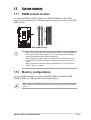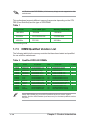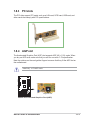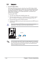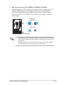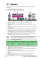
1
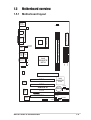
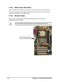
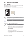
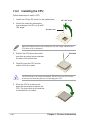
User Guide
Motherboard
P4PE2-X
E1869
Checklist
Revised Edition V2
January 2005
Copyright © 2005 ASUSTeK COMPUTER INC. All Rights Reserved.
No part of this manual, including the products and software described in it, may be
reproduced, transmitted, transcribed, stored in a retrieval system, or translated into any
language in any form or by any means, except documentation kept by the purchaser for
backup purposes, without the express written permission of ASUSTeK COMPUTER INC.
(“ASUS”).
Product warranty or service will not be extended if: (1) the product is repaired, modified or
altered, unless such repair, modification of alteration is authorized in writing by ASUS; or (2)
the serial number of the product is defaced or missing.
ASUS PROVIDES THIS MANUAL “AS IS” WITHOUT WARRANTY OF ANY KIND, EITHER
EXPRESS OR IMPLIED, INCLUDING BUT NOT LIMITED TO THE IMPLIED WARRANTIES
OR CONDITIONS OF MERCHANTABILITY OR FITNESS FOR A PARTICULAR PURPOSE.
IN NO EVENT SHALL ASUS, ITS DIRECTORS, OFFICERS, EMPLOYEES OR AGENTS BE
LIABLE FOR ANY INDIRECT, SPECIAL, INCIDENTAL, OR CONSEQUENTIAL DAMAGES
(INCLUDING DAMAGES FOR LOSS OF PROFITS, LOSS OF BUSINESS, LOSS OF USE
OR DATA, INTERRUPTION OF BUSINESS AND THE LIKE), EVEN IF ASUS HAS BEEN
ADVISED OF THE POSSIBILITY OF SUCH DAMAGES ARISING FROM ANY DEFECT OR
ERROR IN THIS MANUAL OR PRODUCT.
SPECIFICATIONS AND INFORMATION CONTAINED IN THIS MANUAL ARE FURNISHED
FOR INFORMATIONAL USE ONLY, AND ARE SUBJECT TO CHANGE AT ANY TIME
WITHOUT NOTICE, AND SHOULD NOT BE CONSTRUED AS A COMMITMENT BY ASUS.
ASUS ASSUMES NO RESPONSIBILITY OR LIABILITY FOR ANY ERRORS OR
INACCURACIES THAT MAY APPEAR IN THIS MANUAL, INCLUDING THE PRODUCTS
AND SOFTWARE DESCRIBED IN IT.
Products and corporate names appearing in this manual may or may not be registered
trademarks or copyrights of their respective companies, and are used only for identification or
explanation and to the owners’ benefit, without intent to infringe.
ii
Contents
Features
Notices ............................................................................................ v
Safety information .......................................................................... vi
About this guide ............................................................................. vii
P4PE2-X specifications summary ................................................ viii
Chapter 1: Product introduction
1.1
1.2
1.3
Welcome! ........................................................................... 1-2
Package contents ............................................................... 1-2
Special features .................................................................. 1-2
1.3.1 Product Highlights .................................................. 1-2
1.3.2 Unique ASUS features ........................................... 1-3
1.4 Before you proceed ............................................................ 1-4
1.5 Motherboard overview ........................................................ 1-5
1.5.1 Motherboard layout ................................................ 1-5
1.5.2 Placement direction ............................................... 1-6
1.5.3 Screw holes ........................................................... 1-6
1.6 Central Processing Unit (CPU) ........................................... 1-7
1.6.1 Overview ................................................................ 1-7
1.6.2 Installing the CPU .................................................. 1-8
1.7 System memory ................................................................. 1-9
1.7.1 DIMM sockets location ........................................... 1-9
1.7.2 Memory configurations .......................................... 1-9
1.7.3 DIMM Qualified Vendors List ............................... 1-10
1.7.4 Installing a DIMM ..................................................1-11
1.8 Expansion slots ................................................................. 1-11
1.8.1 Standard interrupt assignments ........................... 1-12
1.8.2 IRQ assignments for this motherboard ................ 1-12
1.8.3 PCI slots .............................................................. 1-13
1.8.4 AGP slot ............................................................... 1-13
1.9 Jumpers ............................................................................ 1-14
1.10 Connectors ....................................................................... 1-16
1.10.1 Rear panel connectors ......................................... 1-16
1.10.2 Internal connectors .............................................. 1-17
Chapter 2: BIOS Information
2.1
Managing and updating your BIOS .................................... 2-2
2.1.1 Creating a bootable floppy disk ............................. 2-2
2.1.2 Using AFUDOS to update the BIOS ...................... 2-3
2.1.3 Using AFUDOS to copy BIOS from PC ................. 2-4
iii
Contents
Safeguards
2.2
2.3
2.4
2.5
2.6
2.7
2.1.4 Using ASUS EZ Flash to update the BIOS ............ 2-5
2.1.5 Recovering the BIOS with CrashFree BIOS 2 ....... 2-6
BIOS Setup program .......................................................... 2-8
2.2.1 BIOS menu screen ................................................ 2-9
2.2.2 Menu bar ................................................................ 2-9
2.2.3 Navigation keys ..................................................... 2-9
2.2.4 Menu items .......................................................... 2-10
2.2.5 Sub-menu items ................................................... 2-10
2.2.6 Configuration fields .............................................. 2-10
2.2.7 Pop-up window .................................................... 2-10
2.2.8 Scroll bar .............................................................. 2-10
2.2.9 General help ........................................................ 2-10
Main menu ......................................................................... 2-11
2.3.1 System Time ......................................................... 2-11
2.3.2 System Date ......................................................... 2-11
2.3.3 Legacy Diskette A .................................................2-11
2.3.4 Primary and Secondary IDE Master/Slave .......... 2-12
2.3.6 System Information .............................................. 2-13
Advanced menu ............................................................... 2-14
2.4.1 JumperFree Configuration ................................... 2-14
2.4.2 CPU Configuration ............................................... 2-15
2.4.3 Chipset ................................................................. 2-15
2.4.4 Onboard Devices Configuration ........................... 2-17
2.4.5 PCI PnP ............................................................... 2-19
Power menu ..................................................................... 2-21
2.5.1 Suspend Mode ..................................................... 2-21
2.5.2 Repost Video on S3 Resume ............................... 2-21
2.5.3 ACPI 2.0 Support ................................................. 2-21
2.5.4 ACPI APIC Support .............................................. 2-21
2.5.6 APM Configuration ............................................... 2-22
2.5.7 Hardware Monitor ................................................ 2-23
Boot menu ........................................................................ 2-24
2.6.1 Boot Device Priority ............................................. 2-24
2.6.2 Boot Settings Configuration ................................. 2-24
2.6.3 Security ................................................................ 2-26
Exit menu ......................................................................... 2-28
Chapter 3: Software support
3.1
3.2
iv
Install an operating system ................................................. 3-2
Support CD information ...................................................... 3-2
Notices
Federal Communications Commission Statement
This device complies with Part 15 of the FCC Rules. Operation is subject to
the following two conditions:
•
This device may not cause harmful interference, and
•
This device must accept any interference received including interference that
may cause undesired operation.
The use of shielded cables for connection of the monitor to the graphics card is
required to assure compliance with FCC regulations. Changes or modifications
to this unit not expressly approved by the party responsible for compliance
could void the user’s authority to operate this equipment.
Canadian Department of Communications Statement
This digital apparatus does not exceed the Class B limits for radio noise
emissions from digital apparatus set out in the Radio Interference
Regulations of the Canadian Department of Communications.
This class B digital apparatus complies with Canadian ICES-003.
Where to find more information
Refer to the following sources for additional information and for product and
software updates.
1. ASUS Websites
The ASUS website provides updated information on ASUS hardware and
software products. The ASUS websites are listed in the ASUS Contact
Information on the inside front cover.
2. Optional Documentation
Your product package may include optional documentation, such as warranty
flyers, that may have been added by your dealer. These documents are not
part of the standard package.
v
Safety information
Electrical safety
•
To prevent electrical shock hazard, disconnect the power cable from the
electrical outlet before relocating the system.
•
When adding or removing devices to or from the system, ensure that the power
cables for the devices are unplugged before the signal cables are connected. If
possible, disconnect all power cables from the existing system before you add a
device.
•
Before connecting or removing signal cables from the motherboard, ensure that
all power cables are unplugged.
•
Seek professional assistance before using an adpater or extension cord. These
devices could interrupt the grounding circuit.
•
Make sure that your power supply is set to the correct voltage in your area. If you
are not sure about the voltage of the electrical outlet you are using, contact your
local power company.
•
If the power supply is broken, do not try to fix it by yourself. Contact a qualified
service technician or your retailer.
Operation safety
vi
•
Before installing the motherboard and adding devices on it, carefully read all the
manuals that came with the package.
•
Before using the product, make sure all cables are correctly connected and the
power cables are not damaged. If you detect any damage, contact your dealer
immediately.
•
To avoid short circuits, keep paper clips, screws, and staples away from
connectors, slots, sockets and circuitry.
•
Avoid dust, humidity, and temperature extremes. Do not place the product in any
area where it may become wet.
•
Place the product on a stable surface.
•
If you encounter technical problems with the product, contact a qualified service
technician or your retailer.
About this guide
Conventions used in this guide
To make sure that you perform certain tasks properly, take note of the following
symbols used throughout this manual.
WARNING: Information to prevent injury to yourself when trying to
complete a task.
CAUTION: Information to prevent damage to the components when
trying to complete a task.
IMPORTANT: Information that you MUST follow to complete a task.
NOTE: Tips and additional information to aid in completing a task.
Typography
Bold text
Indicates a menu or an item to select.
Italics
Used to emphasize a word or a phrase.
<Key>
Keys enclosed in the less-than and greater-than sign
indicates that you must press the enclosed key.
Example: <Enter> indicates that you must press the
Enter or Return key.
<Multiple key names>
If you must press two or more keys simultaneously,
the key names are linked with a plus sign (+).
Example: <Ctrl+Alt+D>
Command
Means that you must enter the command exactly as
shown. Example:
At the DOS prompt, type the command line:
FORMAT A:/S
vii
P4PE2-X specifications summary
CPU
Socket 478 for Intel® Pentium® 4 / Celeron processors with
speeds of up to 3.06+ GHz
Intel® Hyper-Threading technology ready
Chipset
Intel 82845PE MCH
Intel 82801DB ICH4
Front Side Bus (FSB)
800*/533/400 MHz
(*Overclocked mode, a CPU with 800MHz FSB requires using a PC3200 DIMM)
Note: • Intel® Prescott CPUs can only support 533MHz FSB on this motherboard.
• 800 MHz FSB works with Intel® Northwood processors only.
Memory
2 x 184-pin DDR DIMM sockets for up to 2GB memory
Supports PC3200*/2700/2100 unbuffered non-ECC DDR
DIMMs (*Overclocked mode, a PC3200 DIMM requires a CPU with
800MHz FSB. Obtain PC3200 DDR DIMMs only from ASUS qualified vendors.)
Expansion slots
1 x AGP 4X (1.5V only)
4 x PCI
IDE
2 x UltraDMA100/66/33 connectors
Audio
ADI AD1888 6-channel audio CODEC
LAN
Realtek® RTL8101L Fast Ethernet controller
Special features
ASUS JumperFree™ mode
ASUS EZ Flash
ASUS CrashFree BIOS2
ASUS CPU Parameter Recall (C.P.R.)
USB 2.0 ready
SFS (Stepless Frequency Selection)
Adjustable CPU Vcore
Rear panel I/O
1 x Parallel port
1 x Serial port
1 x PS/2 keyboard port
1 x PS/2 mouse port
4 x USB 2.0/USB 1.1 ports
1 x RJ-45 port
1 x S/PDIF out port
Line In/Line Out/Microphone ports
Internal I/O
1 x USB 2.0/1.1 connector for 2 additional USB ports
CPU/Chassis fan connectors
20-pin/4-pin ATX 12V power connectors
IDE LED connector
Chassis intrusion connector
GAME/MIDI connector
CD/AUX audio connectors
Front panel audio connector
(continued on the next page)
viii
BIOS features
3Mb Flash EEPROM, AMI BIOS with enhanced ACPI, DMI,
PnP, TCAV, SM BIOS2.3, ASUS C.P.R., ASUS EZ Flash,
ASUS CrashFree BIOS2
Industry standard
PCI 2.2, USB 2.0
Manageability
WOL/WOR by PME
Form Factor
ATX form factor: 12 in x 7.0 in (30.5 cm x 17.8 cm)
Support CD contents
Device drivers
ASUS PC Probe
ASUS LiveUpdate
Anti-virus utility
* Specifications are subject to change without notice.
ix
x
Chapter 1
This chapter describes the features of the
motherboard. It includes brief descriptions of the
motherboard components, and illustrations of the
layout, jumper settings, and connectors.
Product introduction
1.1
Welcome!
Thank you for buying the ASUS® P4PE2-X motherboard!
The motherboard delivers a host of new features and latest technologies making it
another standout in the long line of ASUS quality motherboards!
The motherboard incorporates the Intel® Pentium® 4 Processor in 478-pin package
coupled with the Intel® 845PE chipset to set a new benchmark for a cost-effective
desktop platform solution.
Supporting up to 2GB of system memory with PC3200*/2700/2100 DDR SDRAM,
high-resolution graphics via an AGP 4X slot, USB 2.0, 10/100 Mbps LAN and
6-channel audio features, the P4PE2-X is your affordable vehicle to enter the world
of computing!
Before you start installing the motherboard, and hardware devices on it, check the
items in your package with the list below.
*Overclocking mode
1.2
Package contents
Check your motherboard package for the following items.
ASUS P4PE2-X motherboard
ASUS P4PE2-X series support CD
1 x 80-conductor Ultra DMA cable
1 x floppy drive signal cable
1 x I/O shield
Bag of extra jumper caps
User Guide
If any of the above items is damaged or missing, contact your retailer.
1.3
Special features
1.3.1 Product Highlights
Latest processor technology
The motherboard supports the latest Intel® Pentium® 4 Processor via a 478-pin surface
mount ZIF socket.
1-2
Chapter 1: Product introduction
DDR400 memory support
Employing the Double Data Rate (DDR) memory technology, the P4PE2-X
motherboard supports up to 2GB of system memory using unbuffered non-ECC
PC3200*/2700/2100 DDR DIMMs. Memory support depends on the CPU FSB and
DDR type. See page 1-12 for the CPU and DIMM requirements.
*Overclocking mode
Onboard LAN solution
The motherboard has the Realtek® RTL8101L chipset onboard to support
10BASE-T/100BASE-TX networking protocol.
USB 2.0 technology
The motherboard implements the new Universal Serial Bus (USB) 2.0
specification, extending the connection speed from 12 Mbps on USB 1.1 to a fast
480 Mbps on USB 2.0.
6-channel digital audio
The ADI AD1888 AC ‘97 audio CODEC is onboard to provide 6-channel audio
playback capability. A digital audio connector is present to accommodate the
Sony/Philips Digital Interface (S/PDIF) Out module.
Extreme Overclocking
The motherboard offers robust overclocking options to maximize your system
performance. Overclocking features include: a flexible CPU core voltage
adjustment in 0.025V increments over defaults, the SFS (Stepless Frequency
Selection) feature, an adjustable FSB/DDR ratio and the ASUS C.P.R. (CPU
Parameter Recall).
1.3.2 Unique ASUS features
CrashFree BIOS 2
This feature allows you to restore the original BIOS data from the ASUS support
CD or a floppy with the BIOS image file in case when the BIOS codes and data are
corrupted. This protection eliminates the need to buy a replacement ROM chip.
See page 2-6.
ASUS EZ Flash BIOS
With the ASUS EZ Flash, you can easily update the system BIOS even before
loading the operating system. No need to use a DOS-based utility or boot from a
floppy disk. See page 2-2.
ASUS MyLogo2™
This new feature present in the motherboard allows you to personalize and add
style to your system with customizable boot logos. See pages 2-24.
ASUS P4PE2-X motherboard
1-3
C.P.R. (CPU Parameter Recall)
The C.P.R. feature of the motherboard BIOS allows automatic re-setting to the
BIOS default settings in case the system hangs due to overclocking. When the
system hangs due to overclocking, C.P.R. eliminates the need to open the system
chassis and clear the RTC data. Simply shut down and reboot the system, and
BIOS automatically restores the CPU previous setting for each parameter.
1.4
Before you proceed
Take note of the following precautions before you install motherboard components
or change any motherboard settings.
1.
2.
3.
4.
5.
Unplug the power cord from the wall socket before touching any
component.
Use a grounded wrist strap or touch a safely grounded object or discharge
any static electricity by touching the metal surface of the system chassis.
Hold components by the edges to avoid touching the ICs on them.
Whenever you uninstall any component, place it on a grounded antistatic
pad or in the bag that came with the component.
Before you install or remove any component, ensure that the ATX
power supply is switched off or the power cord is detached from the
power supply. Failure to do so may cause severe damage to the
motherboard, peripherals, and/or components.
Onboard LED
The motherboard comes with a stand-by power LED. When lit, this green LED
indicates that the system is ON, in sleep mode, or in soft-off mode, a reminder that
you should shut down the system and unplug the power cable before removing or
plugging in any motherboard component. The illustration below shows the location
of the onboard LED.
SB_PWR
P4PE2-X
®
ON
Standby
Power
OFF
Powered
Off
P4PE2-X Onboard LED
1-4
Chapter 1: Product introduction
1.5
Motherboard overview
1.5.1 Motherboard layout
PS/2KBMS
T: Mouse
B: Keyboard
CPU_FAN
USB2.0 Top:
T: USB4 RJ-45
B: USB3
Center:Line Out
CD
Below:Mic In
Intel
82845PE
MCH
ATX Power Connector
SEC_IDE
Top:Line In
AUX
PRI_IDE
USBPW34
USBPW12
USB1
USB2
DDR DIMM2 (64 bit,184-pin module)
COM1
DDR DIMM1 (64 bit,184-pin module)
SPDIF_O
Socket 478
PARALLEL PORT
ATX12V
FP_AUDIO
AD1888
Accelerated Graphics Port (AGP)
Intel
82801DB
ICH4
PCI1
RTL
8101L
PCI2
CLRTC
Super
I/O
P4PE2-X
3Mbit
BIOS
CR2032 3V
Lithium Cell
CMOS Power
PCI3
CHA_FAN
®
FLOPPY
PCI4
USBPW56
CHASSIS
GAME
USB56
ASUS P4PE2-X motherboard
SB_PWR
PANEL
1-5
1.5.2 Placement direction
When installing the motherboard, make sure that you place it into the chassis in
the correct orientation. The edge with external ports goes to the rear part of the
chassis as indicated in the image below.
1.5.3 Screw holes
Place seven (7) screws into the holes indicated by circles to secure the
motherboard to the chassis.
Do not overtighten the screws! Doing so may damage the motherboard.
Place this side towards
the rear of the chassis
1-6
Chapter 1: Product introduction
1.6
Central Processing Unit (CPU)
1.6.1 Overview
The motherboard comes with a surface mount 478-pin Zero Insertion Force (ZIF)
socket designed for the Intel® Pentium® 4 processor.
Take note of the marked corner (with gold triangle) on the CPU. This mark should
match a specific corner on the socket to ensure correct installation.
P4PE2-X
®
Gold Arrow
P4PE2-X Socket 478
• Intel® Prescott CPUs can only support 533MHz FSB on this motherboard.
• 800 MHz FSB works with Intel® Northwood processors only.
Incorrect installation of the CPU into the socket may bend the pins and severely
damage the CPU!
Notes on Intel® Hyper-Threading Technology
1.
This motherboard supports Intel® Pentium® 4 CPUs with Hyper-Threading
Technology.
2.
Hyper-Threading Technology is supported under Windows® XP and Linux
2.4.x (kernel) and later versions only. Under Linux, use the Hyper-Threading
compliler to compile the code. If you are using any other operating systems,
disable the Hyper-Threading Technology item in BIOS to ensure system
stability and performance.
3.
It is recommended that you install Windows® XP Service Pack 1.
4.
Make sure to enable the Hyper-Threading Technology item in BIOS before
installing a supported operating system.
5.
For more information on Hyper-Threading Technology, visit www.intel.com/
info/hyperthreading.
ASUS P4PE2-X motherboard
1-7
1.6.2 Installing the CPU
Follow these steps to install a CPU.
1. Locate the 478-pin ZIF socket on the motherboard.
90º~100º angle
2. Unlock the socket by pressing the
lever sideways, then lift it up to a 90°100° angle.
Socket Lever
Make sure that the socket lever is lifted up to 90°-100° angle; otherwise, the
CPU does not fit in completely.
3. Position the CPU above the socket
such that its marked corner matches
the base of the socket lever.
Gold Mark
4. Carefully insert the CPU into the
socket until it fits in place.
The CPU fits only in one correct orientation. DO NOT force the CPU into the
socket to prevent bending the pins and damaging the CPU!
5. When the CPU is in place, push
down the socket lever to secure the
CPU. The lever clicks on the side tab
to indicate that it is locked.
1-8
Chapter 1: Product introduction
1.7
System memory
1.7.1 DIMM sockets location
80 Pins
104 Pins
DIMM2
DIMM1
You can install 64MB, 256MB, 512MB, and 1GB DDR DIMMs into the DIMM
sockets of this motherboard. The following figure illustrates the location of the DDR
DIMM sockets.
P4PE2-X
®
P4PE2-X 184-Pin DDR DIMM Sockets
•
•
•
Make sure to unplug the power supply before adding or removing DIMMs or
other system components. Failure to do so may cause severe damage to
the motherboard and other system components.
When installing long AGP cards, it is recommended to install the memory
modules first. Long AGP cards when installed may interfere with memory
socket.
Make sure that the memory frequency matches the CPU Front Side Bus.
Refer to Table 1 for details.
1.7.2 Memory configurations
You may install double-sided or single-sided DDR DIMMs with 64MB, 128MB,
256MB, 512MB, and 1GB densities into the DIMM sockets.
When using a CPU with 800 MHz FSB, you can only use one DDR 400 DIMM
socket.
ASUS P4PE2-X motherboard
1-9
x16 Double-sided DDR DIMMs (16-bit memory chips) are not supported on this
motherboard.
This motherboard supports different memory frequencies depending on the CPU
FSB (Front Side Bus) and the type of DDR DIMM.
Table 1
CPU FSB
DDR DIMM Type
Memory Frequency
*800 MHz
*PC3200
*400 MHz
533 MHz
PC2700/PC2100
333/266 MHz
400 MHz
PC2100
266 MHz
* Overclocking mode
1.7.3 DIMM Qualified Vendors List
The following table lists the memory modules that have been tested and qualified
for use with this motherboard.
Table 2 Qualified DDR 400 DIMMs
Size
Vendor
256MB
512MB
512MB
256MB
512MB
256MB
256MB
512MB
256MB
512MB
256MB
256MB
256MB
256MB
KINGSTON
KINGSTON
KINGSTON
SAMSUNG
SAMSUNG
SAMSUNG
Hynix
Hynix
MICRON
MICRON
Infineon
Infineon
Hynix
MICRON
Chip Number
HY5DU56822BT-D43
HY5DU56822BT-D43
Heat-Sink Package
K4H560838E-TCCC
K4H560838E-TCCC
K4H560838F-TCCC
HY5DU56822BT-D43
HY5DU56822BT-D43
MT46V32M8TG-5BC
MT46V32M8TG-5BC
HYB25D256800BT-5B
HYB25D256800CE-5C
HY5DU56822BT-D43
MT46V32M8TG-5BC
SS/DS
SS
DS
DS
SS
DS
DS
SS
DS
SS
DS
SS
SS
SS
SS
Part Number
KVR400X64C3A/256
KVR400X64C3A/512
KHX3200A/512
M368L3223ETM-CCC
M368L6423ETM-CCC
M368L6423FTN-CCC
HYMD232646B8J-D43 AA
HYMD264646B8J-D43 AA
MT8VDDT3264AG-40BCB
MT16VDDT6464AG-40BCB
HYS64D32300GU-5-B
HYS64D32300HU-5-C
HYMD232646B8J-D43 AA
MT8VDDT3264AG-40BCB
Max. DIMM
1
1
1
1
1
1
1
1
1
1
1
1
2
2
Obtain DDR DIMMs only from ASUS qualified vendors to ensure system
stability. Visit the ASUS website (www.asus.com) for the latest qualified vendors
list (QVL).
1-10
Chapter 1: Product introduction
1.7.4 Installing a DIMM
DDR DIMM
Follow these steps to install a DIMM.
1. Unlock a DIMM socket by pressing the
retaining clips outward.
2. Align a DIMM on the socket such that the
notch on the DIMM matches the break on
the socket.
3. Firmly insert the DIMM into the socket
until the retaining clips snap back in place
and the DIMM is properly seated.
•
•
1.8
Unlocked
A DDR DIMM is keyed with a notch so that it fits in only one direction. DO
NOT force a DIMM into a socket to avoid damaging the DIMM.
Install only qualified DDR DIMMs on this motherboard. See Table 3.
Expansion slots
To install and configure an expansion card:
1. Install an expansion card following the instructions that came with the chassis.
2. Turn on the system and change the necessary BIOS settings, if any. See
Chapter 2 for BIOS information.
3. Assign an IRQ to the card. Refer to the tables next page.
4. Install the drivers and/or software applications for the expansion card
according to the card documentation.
*ASUS
TheseP4PE2-X
IRQs are usually
available for ISA or PCI devices.
motherboard
1-11
1.8.1 Standard interrupt assignments
IRQ
0
1
2
3*
4*
5*
6
7*
8
9*
10*
11*
12*
13
14*
15*
Priority
Standard Function
1
2
N/A
11
12
13
14
15
3
4
5
6
7
8
9
10
System Timer
Keyboard Controller
Programmable Interrupt
Communications Port (COM2)
Communications Port (COM1)
IRQ holder for PCI steering
Floppy Disk Controller
Printer Port (LPT1)
System CMOS/Real Time Clock
IRQ holder for PCI steering
Advance AC’97 CODEC
Standard PCI Graphics Adapter (VGA)
PS/2 Compatible Mouse Port
Numeric Data Processor
Primary IDE Channel
Secondary IDE Channel
* These IRQs are usually available for ISA or PCI devices.
1.8.2 IRQ assignments for this motherboard
A
PCI slot 1
—
PCI slot 2
—
PCI slot 3
—
PCI slot 4
—
AGP slot
—
Onboard USB controller HC1 shared
Onboard USB controller HC2 —
Onboard USB controller HC3 —
Onboard USB 2.0 controller
—
Onboard LAN
—
B
—
—
—
—
—
—
—
—
—
—
C
D
E
F
G
H
shared —
—
—
—
—
— shared —
—
—
—
—
—
—
— shared —
—
—
— shared —
—
—
— shared —
—
—
—
—
—
—
—
—
— shared —
—
—
—
shared —
—
—
—
—
—
—
—
—
— shared
—
—
—
— shared —
When using PCI cards on shared slots, ensure that the drivers support “Share IRQ”
or that the cards do not need IRQ assignments. Otherwise, conflicts arise between
the two PCI groups making the system unstable and the card inoperable.
1-12
Chapter 1: Product introduction
1.8.3 PCI slots
The PCI slots support PCI cards such as a LAN card, SCSI card, USB card, and
other cards that comply with PCI specifications.
1.8.4 AGP slot
The Accelerated Graphics Port (AGP) slot supports AGP 4X (+1.5V) cards. When
you buy an AGP card, make sure that you ask for one with +1.5V specification.
Note the notches on the card golden fingers to ensure that they fit the AGP slot on
the motherboard.
Install only +1.5V AGP cards.
P4PE2-X
®
Keyed for 1.5v
P4PE2-X Accelerated Graphics Port (AGP)
ASUS P4PE2-X motherboard
1-13
1.9
Jumpers
1. Clear RTC RAM (CLRTC)
This jumper allows you to clear the Real Time Clock (RTC) RAM in CMOS.
You can clear the CMOS memory of date, time, and system setup parameters
by erasing the CMOS RTC RAM data. The RAM data in CMOS, that include
system setup information such as system passwords, is powered by the
onboard button cell battery.
To erase the RTC RAM:
1. Turn OFF the computer and unplug the power cord.
2. Move the jumper cap from pins 1-2 (default) to pins 2-3. Keep the cap on
pins 2-3 for about 5~10 seconds, then move the cap back to pins 1-2.
3. Plug the power cord and turn ON the computer.
4. Hold down the <Del> key during the boot process and enter BIOS setup to
re-enter data.
Except when clearing the RTC RAM, never remove the cap on the jumper
default position. Removing the cap will cause system boot failure!
CLRTC
1 2
P4PE2-X
®
Normal
(Default)
2 3
Clear CMOS
P4PE2-X Clear RTC RAM
You do not need to clear the RTC when the system hangs due to overclocking.
For system failure due to overclocking, use the C.P.R. (CPU Parameter Recall)
feature. Shut down and reboot the system so BIOS can automatically reset
parameter settings to its previous values.
1-14
Chapter 1: Product introduction
2. USB device wake-up (3-pin USBPW12, USBPW34, USBPW56)
Set these jumpers to +5V to wake up the computer from S1 sleep mode (CPU
stopped, DRAM refreshed, system running in low power mode) using the
connected USB devices. Set to +5VSB to wake up from S3 and S4 sleep
modes (no power to CPU, DRAM in slow refresh, power supply in reduced
power mode).
USBPW34
USBPW12
2 3
1 2
+5V
(Default)
+5VSB
USBPW56
1 2
2 3
P4PE2-X
®
+5V
(Default)
+5VSB
P4PE2-X USB Device Wake Up
•
The USB device wake-up feature requires a power supply that can provide
500mA on the +5VSB lead for each USB port. Otherwise, the system would
not power up.
•
The total current consumed must NOT exceed the power supply capability
(+5VSB) whether under normal condition or in sleep mode.
ASUS P4PE2-X motherboard
1-15
1.10 Connectors
This section describes and illustrates the motherboard rear panel and internal
connectors.
1.10.1 Rear panel connectors
1
2
3
4
5
6
10
11
9
8
7
1. PS/2 mouse port. This green 6-pin connector is for a PS/2 mouse.
2. Parallel port. This 25-pin port connects a parallel printer, a scanner, or other
devices.
3. RJ-45 port. This port allows connection to a Local Area Network (LAN) through
a network hub.
4. Line In jack. This Line In (light blue) jack connects a tape player or other audio
sources. In 6-channel mode, the function of this jack becomes Bass/Center.
5. Line Out jack. This Line Out (lime) jack connects a headphone or a speaker.
In 6-channel mode, the function of this jack becomes Front Speaker Out.
6. Microphone jack. This Mic (pink) jack connects a microphone. In 6-channel
mode, the function of this jack becomes Rear Speaker Out.
The functions of the Line Out, Line In, and Microphone jacks change when you
select the 6-channel audio configuration as shown in the following table.
Audio 2, 4 or 6-channel configuration
Light Blue
Lime
Pink
Headphone/
2-Speaker
Line In
Line Out
Mic In
4-Speaker
Line In
Front Speaker Out
Rear Speaker Out
6-Speaker
Bass/Center
Front Speaker Out
Rear Speaker Out
7. USB 2.0 ports 3 and 4. These two 4-pin Universal Serial Bus (USB) ports are
available for connecting USB 2.0 devices.
8. USB 2.0 ports 1 and 2. These two 4-pin Universal Serial Bus (USB) ports are
available for connecting USB 2.0 devices.
9. Serial connector. This port connects to your serial mouse and other serial
devices.
10. S/PDIF out port. This jack connects to external audio output devices.
11. PS/2 keyboard port. This purple connector is for a PS/2 keyboard.
1-16
Chapter 1: Product introduction
1.10.2 Internal connectors
1. IDE connectors (40-1 pin PRI_IDE, SEC_IDE)
This connector supports the provided Ultra DMA 100/66 IDE hard disk ribbon
cable. Connect the cable’s blue connector to the primary (recommended) or
secondary IDE connector, then connect the black connector to the Ultra DMA
100/66 slave device (hard disk drive) and the black connector to the Ultra DMA
100/66 master device.
Follow the hard disk drive documentation when setting the device in master
or slave mode.
•
Pin 20 on each IDE connector is removed to match the covered hole on the
Ultra DMA cable connector. This prevents incorrect orientation when you
connect the cables.
•
The hole near the blue connector on the Ultra DMA cable is intentional.
P4PE2-X
PRI_IDE
SEC_IDE
•
NOTE: Orient the red markings
(usually zigzag) on the IDE
ribbon cable to PIN 1.
®
PIN 1
PIN 1
P4PE2-X IDE Connectors
2. Floppy disk drive connector (34-1 pin FLOPPY)
This connector supports the provided floppy drive ribbon cable. After
connecting one end to the motherboard, connect the other end to the floppy
drive. (Pin 5 is removed to prevent incorrect insertion when using ribbon cables
with pin 5 plug).
FLOPPY
P4PE2-X
®
PIN 1
NOTE: Orient the red markings on
the floppy ribbon cable to PIN 1.
P4PE2-X Floppy Disk Drive Connector
ASUS P4PE2-X motherboard
1-17
3. ATX power connectors (20-pin ATXPWR, 4-pin ATX12V)
These connectors connect to an ATX 12V power supply. The plugs from the
power supply are designed to fit these connectors in only one orientation. Find
the proper orientation and push down firmly until the connectors completely fit.
In addition to the 20-pin ATX power connector, this motherboard requires that
you connect the 4-pin ATX +12V power plug to provide sufficient power to the
CPU.
ATX12V
+12V DC GND
+12V DC GND
P4PE2-X
®
ATXPWR
+12.0VDC
+5VSB
PWR_OK
COM
+5.0VDC
COM
+5.0VDC
COM
+3.3VDC
+3.3VDC
+5.0VDC
+5.0VDC
-5.0VDC
COM
COM
COM
PS_ON#
COM
-12.0VDC
+3.3VDC
Pin 1
P4PE2-X ATX Power Connector
Make sure that your ATX 12V power supply can provide 8A on the +12V lead
and at least 1A on the +5-volt standby lead (+5VSB). The minimum
recommended wattage is 230W, or 300W for a fully configured system. The
system may become unstable and may experience difficulty powering up if the
power supply is inadequate.
4. Internal audio connectors (4-pin CD, AUX)
These connectors allow you to receive stereo audio input from sound sources
such as a CD-ROM, TV tuner, or MPEG card.
CD(Black)
Right Audio Channel
Ground
Ground
Left Audio Channel
AUX(White)
P4PE2-X
®
Right Audio Channel
Ground
Ground
Left Audio Channel
P4PE2-X Internal Audio Connectors
1-18
Chapter 1: Product introduction
5. CPU and chassis fan connectors (3-pin CPU_FAN, CHA_FAN)
The fan connectors support cooling fans of 350mA~740mA (8.88W max.) or a
total of 1A~2.22A (26.64W max.) at +12V. Connect the fan cables to the fan
connectors on the motherboard, making sure that the black wire of each cable
matches the ground pin of the connector.
Rotation
+12V
GND
CPU_FAN
Rotation
+12V
GND
CHA_FAN
P4PE2-X
®
P4PE2-X 12-Volt Fan Connectors
Do not forget to connect the fan cables to the fan connectors. Lack of sufficient
air flow within the system may damage the motherboard components. These
are not jumpers! DO NOT place jumper caps on the fan connectors!
6. USB header (10-1 pin USB56)
USB+5V
USB_P6USB_P6+
GND
NC
If the USB ports on the rear panel are inadequate, a USB header is available
for additional USB ports. Connect the USB cable of the USB 2.0 module to this
header. You may install the USB module in the chassis front panel. The
module has two USB 2.0 ports for connecting next generation USB peripherals
such as high resolution cameras, scanners, and printers.
1
®
P4PE2-X USB 2.0 Header
•
•
USB+5V
USB_P5USB_P5+
GND
USB56
P4PE2-X
The USB 2.0 module is purchased separately.
Install the USB 2.0 driver before using the USB 2.0 feature.
ASUS P4PE2-X motherboard
1-19
7. Front panel audio connector (10-1 pin FP_AUDIO)
This is an interface for the front panel cable that allows convenient connection
and control of audio devices.
BLINE_OUT_L
AGND
+5VA
BLINE_OUT_R
Be default, the pins labeled LINE OUT_R/BLINE_OUT_R and the pins
LINE OUT_L/BLINE_OUT_L are shorted with jumper caps. Remove the caps
only when you are connecting the front panel audio cable.
MIC2
MICPWR
Line out_R
NC
Line out_L
FP_AUDIO
P4PE2-X
®
P4PE2-X Front Panel Audio Connector
8. Chassis intrusion connector (4-1 pin CHASSIS)
This lead is for a chassis designed with intrusion detection feature. This
requires an external detection mechanism such as a chassis intrusion sensor
or microswitch. When you remove any chassis component, the sensor triggers
and sends a high-level signal to this lead to record a chassis intrusion event.
By default, the pins labeled “Chassis Signal” and “Ground” are shorted with a
jumper cap. If you wish to use the chassis intrusion detection feature, remove
the jumper cap from the pins.
Chassis Signal
GND
+5VSB_MB
CHASSIS
P4PE2-X
®
(Default)
P4PE2-X Chassis Alarm Lead
1-20
Chapter 1: Product introduction
9. GAME/MIDI connector (16-1 pin GAME)
+5V
J2B1
J2CX
MIDI_OUT
J2CY
J2B2
MIDI_IN
This connector supports a GAME/MIDI module. If a GAME/MIDI module is
available, connect the GAME/MIDI cable to this connector. The GAME/MIDI
port on the module connects a joystick or a game pad for playing games, and
MIDI devices for playing or editing audio files.
P4PE2-X
GAME
+5V
J1B1
J1CX
GND
GND
J1CY
J1B2
+5V
®
P4PE2-X Game Connector
The GAME/MIDI module is purchased separately.
10. System panel connector (20-1 pin PANEL)
This connector accommodates several system front panel functions.
IDE_LED
P4PE2-X
®
+5V
Ground
Ground
Speaker
Reset
Ground
PWR
Ground
PLED-
IDE_LED+
IDE_LED-
PLED+
Power LED
Speaker
Connector
Reset SW
ATX Power
Switch*
* Requires an ATX power supply.
P4PE2-X System Panel Connector
•
System Power LED Lead (Green 3-1 pin PLED)
This 3-1 pin connector connects to the system power LED. The LED lights up
when you turn on the system power, and blinks when the system is in sleep
mode.
•
System Warning Speaker Lead (Orange 4-pin SPKR)
This 4-pin connector connects to the case-mounted speaker and allows you to
hear system beeps and warnings.
ASUS P4PE2-X motherboard
1-21
•
Reset Switch Lead (Blue 2-pin RESET)
This 2-pin connector connects to the case-mounted reset switch for rebooting
the system without turning off the system power.
• ATX Power Switch / Soft-Off Switch Lead (Yellow 2-pin PWRBTN )
This connector connects a switch that controls the system power. Pressing the
power switch turns the system between ON and SLEEP, or ON and SOFT
OFF, depending on the BIOS or OS settings. Pressing the power switch while
in the ON mode for more than four seconds turns the system OFF.
•
Hard disk activity LED (Red 2-pin IDE_LED)
This connector supplies power to the hard disk activity LED. Any read or write
activity of an IDE device causes this LED to light up.
The System Panel connector is color-coded for easy and foolproof connection.
Take note of the specific connector colors as described.
1-22
Chapter 1: Product introduction