1
UB-R02
Technical Reference
Guide
EPSON
English
Rev. C
404963402
UB-R02 Technical Reference Guide
CAUTIONS
❏
This document shall apply only to the product(s) identified herein.
❏
No part of this document may be reproduced, stored in a retrieval system, or transmitted in any form or by any
means, electronic, mechanical, photocopying, recording, or otherwise, without the prior written permission of
Seiko Epson Corporation.
❏
The contents of this document are subject to change without notice. Please contact us for the latest information.
❏
While every precaution has been taken in the preparation of this document, Seiko Epson Corporation assumes no
responsibility for errors or omissions.
❏
Neither is any liability assumed for damages resulting from the use of the information contained herein.
❏
Neither Seiko Epson Corporation nor its affiliates shall be liable to the purchaser of this product or third parties
for damages, losses, costs, or expenses incurred by the purchaser or third parties as a result of: accident, misuse, or
abuse of this product or unauthorized modifications, repairs, or alterations to this product, or (excluding the U.S.)
failure to strictly comply with Seiko Epson Corporation's operating and maintenance instructions.
❏
Seiko Epson Corporation shall not be liable against any damages or problems arising from the use of any options
or any consumable products other than those designated as Original EPSON Products or EPSON Approved
Products by Seiko Epson Corporation.
TRADEMARKS
®
®
EPSON and ESC/POS are registered trademarks of Seiko Epson Corporation.
Microsoft® Windows® and Windows NT® are registered trademarks of Microsoft Corporation.
General Notice: Other product and company names used herein are for identification purposes only and may be
trademarks of their respective companies.
ESC/POS Proprietary Command System
EPSON took the initiative by introducing ESC/POS, a proprietary POS printer command system including patented
commands and enabling versatile POS system construction with high scalability. Compatible with all types of EPSON
POS printers and displays, this proprietary control system also offers the flexibility to easily make future upgrades. Its
popularity is worldwide.
Rev. C
i
The influence on the environment of radio wave radiation
❏ The Radio Frequency module that can be installed in this product radiates the same high
frequency energy as some other high frequency devices but the level of the energy radiated
from it is suppressed so that it is much lower than the electromagnetic energy radiated from
radio equipment like cell phones.
❏ Under some situations and in certain environments, the use of this equipment is sometimes
limited by the owner of the building or a representative with responsibility for the group.
For example, it may be restricted in the following case:
•
Use in an environment where it may cause interference with other devices and services.
❏ If you do not understand the radio device usage policy in a specific group or environment,
such as an airport, ask permission before turning on the power of this product.
The influence on the human body of radio wave radiation
The output power radiated from the Radio Frequency module that can be installed in this
product is much lower than the radiation limit specified in the safety standard. However, it is
best to avoid allowing this product to contact your body during usual operation. While using, be
especially careful not to touch the cover of the antenna. (See “Chapter 1 Part Names“for the
location of the antenna.)
Note about interference
❏ The Radio Frequency module that can be installed in this product generates, uses, and can
radiate radio frequency energy and, if not installed and used in accordance with the
instruction manual, may cause harmful interference to radio communications.
❏ If this equipment does cause harmful interference to radio or television reception, which can
be determined by turning the equipment off and on, the user is encouraged to try to correct
the interference by one or more of the following measures:
•
-Reorient or relocate the receiving antenna.
•
-Increase the separation between the equipment and receiver.
•
-Connect the equipment into an outlet on a circuit different from that to which the
receiver is connected.
•
-Consult your dealer or an experienced radio/TV technician for help.
❏ Never disassemble or modify this product or the installed Radio Frequency module.
❏ Seiko Epson Corporation shall not be liable for interference to radio/TV resulting from
changes or modifications to this product or the installed Radio Frequency module not
expressly approved by Seiko Epson Corporation.
ii
Rev. C
UB-R02 Technical Reference Guide
❏ Other radio equipment sometimes uses the same frequency band that this unit uses. To
prevent radio wave interference with other radio equipment, pay attention to the following
matters when you use this product:
•
The Radio Frequency module that can be installed in this product uses the Industrial
Scientific and Medical band (2.4 GHz), DS-SS modulation, and the interference distance
is 40 m.
•
Other equipment that uses the same frequency band used by the Radio Frequency
module that can be installed in this product includes equipment for industry, science
and medical treatment, microwave ovens, HomeRF, and radio and other broadcasting
equipment (both ones that require a license and ones that do not require a license).
1. Confirm that radio and other broadcasting equipment are not used nearby before using
this product.
2. When trouble occurs, for example, if the Radio Frequency module causes problems such
as radio wave interference, consult your dealer.
Rev. C
iii
Note about security
This section describes security concerns when using a wireless LAN by using the Radio
Frequency module that can be installed in this product. Please also see the security information
in Appendix A.
Security is important for the protection of the user’s privacy
A wireless LAN has the advantage that information can be exchanged by using radio waves
instead of a cable. However, radio waves are not confined to a cable and can be received in a
fairly wide area and through obstacles such as walls, so if security is not used, the following
problems may occur.
Communication data can be received by stealth.
A third person can receive private communication data by intercepting the radio waves
intentionally. Such a person could receive items such as the following:
Personal information, such a an ID and password or credit card number
The contents of e-mail.
Data which is communicated between the PC and printer.
Illegal access
A third person can access the network and cause damage such as the following:
Personal information and secret information can be removed.
Invalid information can be sent as if it were from a legitimate user of the network.
Intercepted communication contents can be re-written and sent.
Data and the system can be destroyed by an electronic virus.
This product, the wireless LAN card, and the access point have security mechanisms to counter
these problems. If you use the security settings for this product, you can nearly eliminate these
problems.
In some cases, the wireless LAN equipment is not set up before it is sold to the user. Therefore,
to attempt to prevent security problems, always use all the security settings for the wireless
LAN equipment according to the manual.
The security functions, however, cannot guarantee 100% security. Please understand this when
you use this product.
When you cannot set the security by yourself, please ask your dealer.
Seiko Epson Corporation suggests that the security setting is set by the judgment and the
responsibility of user after understanding the possible problems resulting from using this
product without the security settings.
For details about wireless LAN security, see Appendix A “Wireless LAN Security.“
iv
Rev. C
UB-R02 Technical Reference Guide
Revision Information
Revision
Page
Altered Items and Contents
Rev. A
All pages
Newly authorized
1-2
Add the Communication Distance
1-3
Add the Setting Dimension
Chapter 2
Add a procedure
A-3
Security Function Overview
A-4
Add the Q&A
B-7
Add the confirmed access point
ix,1-2,2-7,2-10,2-12,
3-14,3-15,B-1,B-3,B-6
Add the RF module
Rev. B
Rev. C
Rev. C
v
Key to Symbols
The following symbols are used in the documentation for this product. See the specific warnings
and cautions at appropriate points throughout this guide.
WARNING:
Warnings must be followed carefully to avoid serious bodily injury.
CAUTION:
Cautions must be observed to avoid minor injury to yourself or damage to your
equipment.
Note:
Notes have important information and useful tips on the operation of your printer.
Safety Precautions
This section presents important information to ensure safe and effective use of this product.
Please read this section carefully and store it in an accessible location.
CAUTION:
❏ Be careful to avoid dropping conductive objects such as paper clips on the circuit board, as
they could short circuit connections and cause damage from excessive current.
❏ This product should only be connected to the devices specified in this guide. Connecting
other devices could cause damage, fire or explosion.
❏ Never disassemble or modify this product. Tampering with this product may result in
injury, fire, or electric shock.
❏ Be sure to set the product on a firm, stable, horizontal surface. The product may break or
cause injury if it falls.
❏ Do not use in locations subject to high temperature, humidity or dust levels.
Excessive temperature, humidity or dust may cause equipment damage, fire, or shock.
❏ Parts on the circuit board may become hot during operation. Therefore, wait approximately
10 minutes after turning the power off before touching them.
❏ To prevent the possibility of electrical shock, do not perform installation or connect cables
during a thunderstorm.
vi
Rev. C
UB-R02 Technical Reference Guide
Product Servicing
This product cannot be serviced at the component level. If damage occurs, the UB-R02 should be
replaced as a unit.
About This Guide
This guide is intended to provide all information necessary for system planning, design,
installation and application of the UB-R02 for designers and developers of POS systems.
Contents of the Guide
The configuration of the guide is as follows:
Chapter 1, “System Provisions”
Supported operating system, network
protocols, TM printers, and other limitations.
Chapter 2, “Installation”
Gives information on how to install and use the
UB-R02.
Chapter 3, “Utilities”
Gives information on how to use the utilities.
Chapter 4, “Programming Samples”
Includes practical programming information.
Chapter 5, “Specifications”
Gives specifications.
Appendix A, “Wireless LAN Network
Composition”
Gives explanation of the network composition
of the Wireless LAN.
Appendix B, “FAQ”
Gives FAQ.
Related Software and Documents
Software/document name
Description
UB-R02 User’s Manual
Provides instructions for operators of POS systems in which the
UB-R02 is installed so that the operators can use the UB-R02 safely
and correctly.
Rev. C
vii
EMC and Safety Standards Applied
Product Name:
Model Name:
UB-R02
M195A
The following standards are applied only to the interface boards that are so labeled. (EMC is tested using EPSON
power supplies.)
Europe:
CE marking
North America:
EMI:
FCC/ICES-003 Class A
Oceania:
EMC:
AS/NZS 3548/CISPR Class B
WARNING
The connection of a non-shielded interface cable to this board will invalidate the EMC standards of this device.
You are cautioned that changes or modifications not expressly approved by Seiko Epson Corporation could void your
authority to operate the equipment.
CE Marking
The printer conforms to the following Directives and Norms:
Directive 89/336/EEC
EN 55022 Class B
EN 55024
IEC 61000-4-2
IEC 61000-4-3
IEC 61000-4-4
IEC 61000-4-5
IEC 61000-4-6
IEC 61000-4-11
The printer in which this board is installed does not conform to the following:
Directive 90/384/EEC
EN45501
FCC Compliance Statement
For American Users
This equipment has been tested and found to comply with the limits for a Class A digital device, pursuant to Part 15 of
the FCC Rules. These limits are designed to provide reasonable protection against harmful interference when the
equipment is operated in a commercial environment.
This equipment generates, uses, and can radiate radio frequency energy and, if not installed and used in accordance
with the instruction manual, may cause harmful interference to radio communications. Operation of this equipment in
a residential area is likely to cause harmful interference, in which case the user will be required to correct the
interference at his own expense.
For Canadian Users
This Class A digital apparatus complies with Canadian ICES-003.
Cet appareil numérique de la classe A est conforme à la norme NMB-003 du Canada.
viii
Rev. C
UB-R02 Technical Reference Guide
RF Module
This equipment contains the following wireless module.
H/W Version
Ver.1.0
Ver.2.0
Manufacturer
Universal Scientific Industrial Co.Ltd
TOYOTA Industrial Co.Ltd
Model Name
CF114100
6180210
Product Name
USI WLAN CompactFlash Card Type I
WIRELESS CompactFlash Card Type I
USA
This device conforms to Part 15 of the FCC rules.
This device has been tested and found to comply with the limits for a Class B digital device, pursuant to Part 15 of the
FCC Rules. These limits are designed to provide reasonable protection against harmful interference in a residential
installation. This equipment generates, uses, and can radiate radio frequency energy and, if not installed and used in
accordance with the instruction manual, may cause harmful interference to radio communications. However, there is
no guarantee that interference will not occur in a particular installation. If this equipment does cause harmful
interference to radio or television reception, which can be determined by turning the equipment off and on, the user is
encouraged to try to correct the interference by one or more of the following measures:
-Reorient or relocate the receiving antenna.
-Increase the separation between the equipment and receiver.
-Connect the equipment into an outlet on a circuit different from that to which the receiver is connected.
-Consult the dealer or an experienced radio/TV technician for help.
For body worn operation, this CF114100 has been tested and meets the FCC RF exposure guidelines when used with
the Universal Scientific Industrial Co., Ltd. accessories supplied or designated for this product. Use of other accessories
may not ensure compliance with FCC RF exposure guidelines.
CANADA
This device conforms to IC, Low Power License-Exempt Radio Communication Devices (RSS-210).
The information such as Certification No., Model Name, and Manufacturer Name are described on the surface of the
module.
EUROPE
Hereby, Universal Scientific Industrial Co., Ltd., declares that this CF114100 is in compliance with the essential
requirements and other relevant provisions of Directive 1999/5/EC.
The UB-R02 can be used only in the countries listed below:
Austria, Belgium, Germany, Luxembourg, Netherlands, Switzerland, France, Italy, Greece, Spain, Portugal, Denmark,
Finland, Ireland, Sweden, UK, USA, Canada, Australia, and New Zealand.
Rev. C
ix
How to Use this Guide
Installation Overview
Be sure to read Chapter 1 “System Provisions“ before using the product.
Perform the following steps to install and configure the UB-R02. See the indicated chapters for
detailed information.
1. Install the UB-R02 in your printer. See Chapter 2.
2. Install the TCP/IP protocol in your operating system, if necessary. See Chapter 3.
3. Set the functions of the UB-R02. See Chapter 5.
Programming
Chapter 4 provides you with a sample program of printing by using a network.
x
Rev. C
UB-R02 Technical Reference Guide
Contents
The influence on the environment of radio wave radiation . . . . . . . . . . . . . . . . . . . . . . . . . . . . . . . .ii
The influence on the human body of radio wave radiation . . . . . . . . . . . . . . . . . . . . . . . . . . . . . . . .ii
Note about interference . . . . . . . . . . . . . . . . . . . . . . . . . . . . . . . . . . . . . . . . . . . . . . . . . . . . . . . . . . . . .ii
Note about security . . . . . . . . . . . . . . . . . . . . . . . . . . . . . . . . . . . . . . . . . . . . . . . . . . . . . . . . . . . . . . . . . . . . .iv
Revision Information . . . . . . . . . . . . . . . . . . . . . . . . . . . . . . . . . . . . . . . . . . . . . . . . . . . . . . . . . . . . . . . . . . . .v
Key to Symbols . . . . . . . . . . . . . . . . . . . . . . . . . . . . . . . . . . . . . . . . . . . . . . . . . . . . . . . . . . . . . . . . . . . . . . . . .vi
Safety Precautions . . . . . . . . . . . . . . . . . . . . . . . . . . . . . . . . . . . . . . . . . . . . . . . . . . . . . . . . . . . . . . . . . . . . . .vi
Product Servicing . . . . . . . . . . . . . . . . . . . . . . . . . . . . . . . . . . . . . . . . . . . . . . . . . . . . . . . . . . . . . . . . . . .vii
About This Guide . . . . . . . . . . . . . . . . . . . . . . . . . . . . . . . . . . . . . . . . . . . . . . . . . . . . . . . . . . . . . . . . . . . . . . .vii
Contents of the Guide . . . . . . . . . . . . . . . . . . . . . . . . . . . . . . . . . . . . . . . . . . . . . . . . . . . . . . . . . . . . . . .vii
Related Software and Documents . . . . . . . . . . . . . . . . . . . . . . . . . . . . . . . . . . . . . . . . . . . . . . . . . . . . .vii
EMC and Safety Standards Applied . . . . . . . . . . . . . . . . . . . . . . . . . . . . . . . . . . . . . . . . . . . . . . . . . . . . . . .viii
CE Marking . . . . . . . . . . . . . . . . . . . . . . . . . . . . . . . . . . . . . . . . . . . . . . . . . . . . . . . . . . . . . . . . . . . . . . . .viii
FCC Compliance Statement
For American Users . . . . . . . . . . . . . . . . . . . . . . . . . . . . . . . . . . . . . . . . . . . . . . . . . . . . . . . . . . . . . . . . . .viii
For Canadian Users . . . . . . . . . . . . . . . . . . . . . . . . . . . . . . . . . . . . . . . . . . . . . . . . . . . . . . . . . . . . . . . . .viii
RF Module . . . . . . . . . . . . . . . . . . . . . . . . . . . . . . . . . . . . . . . . . . . . . . . . . . . . . . . . . . . . . . . . . . . . . . . . . . . . .ix
USA . . . . . . . . . . . . . . . . . . . . . . . . . . . . . . . . . . . . . . . . . . . . . . . . . . . . . . . . . . . . . . . . . . . . . . . . . . . . . . .ix
CANADA . . . . . . . . . . . . . . . . . . . . . . . . . . . . . . . . . . . . . . . . . . . . . . . . . . . . . . . . . . . . . . . . . . . . . . . . . .ix
EUROPE . . . . . . . . . . . . . . . . . . . . . . . . . . . . . . . . . . . . . . . . . . . . . . . . . . . . . . . . . . . . . . . . . . . . . . . . . . .ix
How to Use this Guide . . . . . . . . . . . . . . . . . . . . . . . . . . . . . . . . . . . . . . . . . . . . . . . . . . . . . . . . . . . . . . . . . . .x
Installation Overview . . . . . . . . . . . . . . . . . . . . . . . . . . . . . . . . . . . . . . . . . . . . . . . . . . . . . . . . . . . . . . . .x
Programming . . . . . . . . . . . . . . . . . . . . . . . . . . . . . . . . . . . . . . . . . . . . . . . . . . . . . . . . . . . . . . . . . . . . . .x
Contents . . . . . . . . . . . . . . . . . . . . . . . . . . . . . . . . . . . . . . . . . . . . . . . . . . . . . . . . . . . . . . . . . . . . . . . . . .xi
Chapter 1 System Provisions
1.1 Introduction . . . . . . . . . . . . . . . . . . . . . . . . . . . . . . . . . . . . . . . . . . . . . . . . . . . . . . . . . . . . . . . . . . . . . . . .1-1
1.2 Limitations . . . . . . . . . . . . . . . . . . . . . . . . . . . . . . . . . . . . . . . . . . . . . . . . . . . . . . . . . . . . . . . . . . . . . . . . . .1-1
1.3 Usable Countries . . . . . . . . . . . . . . . . . . . . . . . . . . . . . . . . . . . . . . . . . . . . . . . . . . . . . . . . . . . . . . . . . . . .1-2
1.4 Supported TM Printers . . . . . . . . . . . . . . . . . . . . . . . . . . . . . . . . . . . . . . . . . . . . . . . . . . . . . . . . . . . . . . . .1-2
1.5 Communication Distance . . . . . . . . . . . . . . . . . . . . . . . . . . . . . . . . . . . . . . . . . . . . . . . . . . . . . . . . . . . .1-2
1.6 Operating Environments . . . . . . . . . . . . . . . . . . . . . . . . . . . . . . . . . . . . . . . . . . . . . . . . . . . . . . . . . . . . . .1-2
1.6.1 Supported Operating Systems . . . . . . . . . . . . . . . . . . . . . . . . . . . . . . . . . . . . . . . . . . . . . . . . . . . .1-2
1.6.2 Supported Protocols . . . . . . . . . . . . . . . . . . . . . . . . . . . . . . . . . . . . . . . . . . . . . . . . . . . . . . . . . . . .1-2
1.6.3 Environments for Setup Utility . . . . . . . . . . . . . . . . . . . . . . . . . . . . . . . . . . . . . . . . . . . . . . . . . . . . .1-3
1.7 Unpacking . . . . . . . . . . . . . . . . . . . . . . . . . . . . . . . . . . . . . . . . . . . . . . . . . . . . . . . . . . . . . . . . . . . . . . . . .1-3
1.8 Space Required for Installation . . . . . . . . . . . . . . . . . . . . . . . . . . . . . . . . . . . . . . . . . . . . . . . . . . . . . . . .1-3
1.9 Part Names . . . . . . . . . . . . . . . . . . . . . . . . . . . . . . . . . . . . . . . . . . . . . . . . . . . . . . . . . . . . . . . . . . . . . . . . .1-4
1.10 UB-R02 Initial Setting . . . . . . . . . . . . . . . . . . . . . . . . . . . . . . . . . . . . . . . . . . . . . . . . . . . . . . . . . . . . . . . . .1-4
Chapter 2 Installation
2.1 Installation Precautions Cautions and Note . . . . . . . . . . . . . . . . . . . . . . . . . . . . . . . . . . . . . . . . . . . . . .2-1
2.2 Network Equipment . . . . . . . . . . . . . . . . . . . . . . . . . . . . . . . . . . . . . . . . . . . . . . . . . . . . . . . . . . . . . . . . . .2-2
2.2.1 Ad-Hoc Mode . . . . . . . . . . . . . . . . . . . . . . . . . . . . . . . . . . . . . . . . . . . . . . . . . . . . . . . . . . . . . . . . .2-2
2.2.2 Infrastructure Mode . . . . . . . . . . . . . . . . . . . . . . . . . . . . . . . . . . . . . . . . . . . . . . . . . . . . . . . . . . . . .2-3
2.2.3 Network Information Needed . . . . . . . . . . . . . . . . . . . . . . . . . . . . . . . . . . . . . . . . . . . . . . . . . . . .2-4
2.3 Outline of the Process . . . . . . . . . . . . . . . . . . . . . . . . . . . . . . . . . . . . . . . . . . . . . . . . . . . . . . . . . . . . . . . .2-5
2.4 Connect the UB-R02 to the TM Printer . . . . . . . . . . . . . . . . . . . . . . . . . . . . . . . . . . . . . . . . . . . . . . . . . . .2-5
2.4.1 Preparation . . . . . . . . . . . . . . . . . . . . . . . . . . . . . . . . . . . . . . . . . . . . . . . . . . . . . . . . . . . . . . . . . . . .2-5
2.4.2 UB-R02 Connection . . . . . . . . . . . . . . . . . . . . . . . . . . . . . . . . . . . . . . . . . . . . . . . . . . . . . . . . . . . . .2-6
2.4.3 Print the status sheet . . . . . . . . . . . . . . . . . . . . . . . . . . . . . . . . . . . . . . . . . . . . . . . . . . . . . . . . . . . .2-7
2.4.4 Default Setting Value . . . . . . . . . . . . . . . . . . . . . . . . . . . . . . . . . . . . . . . . . . . . . . . . . . . . . . . . . . .2-8
Rev. C
xi
2.5 Setting of the Setting PC . . . . . . . . . . . . . . . . . . . . . . . . . . . . . . . . . . . . . . . . . . . . . . . . . . . . . . . . . . . . . . 2-8
2.5.1 Setting of the Setting PC . . . . . . . . . . . . . . . . . . . . . . . . . . . . . . . . . . . . . . . . . . . . . . . . . . . . . . . . . 2-8
2.5.2 Setting the Wireless LAN by the TMNetWinConfig . . . . . . . . . . . . . . . . . . . . . . . . . . . . . . . . . . . . 2-9
2.5.3 Print the status sheet . . . . . . . . . . . . . . . . . . . . . . . . . . . . . . . . . . . . . . . . . . . . . . . . . . . . . . . . . . . . 2-12
2.6 Setting of the Network PC . . . . . . . . . . . . . . . . . . . . . . . . . . . . . . . . . . . . . . . . . . . . . . . . . . . . . . . . . . . . 2-12
2.6.1 Confirmation of the connection . . . . . . . . . . . . . . . . . . . . . . . . . . . . . . . . . . . . . . . . . . . . . . . . . . 2-12
2.6.2 Downloading of the Printer Driver . . . . . . . . . . . . . . . . . . . . . . . . . . . . . . . . . . . . . . . . . . . . . . . . . 2-13
2.6.3 Setting up the Driver . . . . . . . . . . . . . . . . . . . . . . . . . . . . . . . . . . . . . . . . . . . . . . . . . . . . . . . . . . . . 2-13
2.6.4 Printout Test . . . . . . . . . . . . . . . . . . . . . . . . . . . . . . . . . . . . . . . . . . . . . . . . . . . . . . . . . . . . . . . . . . . 2-13
2.7 Initializing the UB-R02 . . . . . . . . . . . . . . . . . . . . . . . . . . . . . . . . . . . . . . . . . . . . . . . . . . . . . . . . . . . . . . . . . 2-14
Chapter 3 Utilities
3.1 Setting the TCP/IP Protocol in Your Operating System . . . . . . . . . . . . . . . . . . . . . . . . . . . . . . . . . . . . . 3-1
3.1.1 Windows 2000 . . . . . . . . . . . . . . . . . . . . . . . . . . . . . . . . . . . . . . . . . . . . . . . . . . . . . . . . . . . . . . . . . 3-1
3.1.2 Windows XP . . . . . . . . . . . . . . . . . . . . . . . . . . . . . . . . . . . . . . . . . . . . . . . . . . . . . . . . . . . . . . . . . . . 3-2
3.2 TMNetWinConfig . . . . . . . . . . . . . . . . . . . . . . . . . . . . . . . . . . . . . . . . . . . . . . . . . . . . . . . . . . . . . . . . . . . . 3-3
3.2.1 Preparation . . . . . . . . . . . . . . . . . . . . . . . . . . . . . . . . . . . . . . . . . . . . . . . . . . . . . . . . . . . . . . . . . . . 3-3
3.2.2 Install . . . . . . . . . . . . . . . . . . . . . . . . . . . . . . . . . . . . . . . . . . . . . . . . . . . . . . . . . . . . . . . . . . . . . . . . . 3-3
3.2.3 Operating . . . . . . . . . . . . . . . . . . . . . . . . . . . . . . . . . . . . . . . . . . . . . . . . . . . . . . . . . . . . . . . . . . . . . 3-6
3.2.4 Functions . . . . . . . . . . . . . . . . . . . . . . . . . . . . . . . . . . . . . . . . . . . . . . . . . . . . . . . . . . . . . . . . . . . . . 3-9
3.2.5 Settings . . . . . . . . . . . . . . . . . . . . . . . . . . . . . . . . . . . . . . . . . . . . . . . . . . . . . . . . . . . . . . . . . . . . . . . 3-13
Chapter 4 Programming Samples
4.1 Method of Printing to the UB-R02 . . . . . . . . . . . . . . . . . . . . . . . . . . . . . . . . . . . . . . . . . . . . . . . . . . . . . . . 4-1
4.2 Direct Printing by PORT 9100 . . . . . . . . . . . . . . . . . . . . . . . . . . . . . . . . . . . . . . . . . . . . . . . . . . . . . . . . . . 4-2
4.2.1 For Windows Console . . . . . . . . . . . . . . . . . . . . . . . . . . . . . . . . . . . . . . . . . . . . . . . . . . . . . . . . . . . 4-2
4.2.2 For Linux . . . . . . . . . . . . . . . . . . . . . . . . . . . . . . . . . . . . . . . . . . . . . . . . . . . . . . . . . . . . . . . . . . . . . . 4-3
4.3 Monitoring of the ASB status . . . . . . . . . . . . . . . . . . . . . . . . . . . . . . . . . . . . . . . . . . . . . . . . . . . . . . . . . . . 4-4
4.4 The Priorities of Printing . . . . . . . . . . . . . . . . . . . . . . . . . . . . . . . . . . . . . . . . . . . . . . . . . . . . . . . . . . . . . . . 4-4
4.5 Time-out for Connection . . . . . . . . . . . . . . . . . . . . . . . . . . . . . . . . . . . . . . . . . . . . . . . . . . . . . . . . . . . . . . 4-4
Chapter 5 Specifications
5.1 Structure . . . . . . . . . . . . . . . . . . . . . . . . . . . . . . . . . . . . . . . . . . . . . . . . . . . . . . . . . . . . . . . . . . . . . . . . . . . 5-1
5.1.1 Printer Connection . . . . . . . . . . . . . . . . . . . . . . . . . . . . . . . . . . . . . . . . . . . . . . . . . . . . . . . . . . . . . 5-1
5.1.2 Line Display Connection . . . . . . . . . . . . . . . . . . . . . . . . . . . . . . . . . . . . . . . . . . . . . . . . . . . . . . . . . 5-1
5.2 Features . . . . . . . . . . . . . . . . . . . . . . . . . . . . . . . . . . . . . . . . . . . . . . . . . . . . . . . . . . . . . . . . . . . . . . . . . . . 5-2
5.2.1 Overview . . . . . . . . . . . . . . . . . . . . . . . . . . . . . . . . . . . . . . . . . . . . . . . . . . . . . . . . . . . . . . . . . . . . . 5-2
5.2.2 Printing Functions . . . . . . . . . . . . . . . . . . . . . . . . . . . . . . . . . . . . . . . . . . . . . . . . . . . . . . . . . . . . . . . 5-2
5.2.3 Functions to Monitor Settings . . . . . . . . . . . . . . . . . . . . . . . . . . . . . . . . . . . . . . . . . . . . . . . . . . . . . 5-2
5.2.4 Maintenance Functions . . . . . . . . . . . . . . . . . . . . . . . . . . . . . . . . . . . . . . . . . . . . . . . . . . . . . . . . . 5-2
5.3 Hardware Specifications . . . . . . . . . . . . . . . . . . . . . . . . . . . . . . . . . . . . . . . . . . . . . . . . . . . . . . . . . . . . . 5-3
5.3.1 Physical communications standard: . . . . . . . . . . . . . . . . . . . . . . . . . . . . . . . . . . . . . . . . . . . . . . . 5-3
5.3.2 External size . . . . . . . . . . . . . . . . . . . . . . . . . . . . . . . . . . . . . . . . . . . . . . . . . . . . . . . . . . . . . . . . . . . 5-3
5.3.3 Mode Button . . . . . . . . . . . . . . . . . . . . . . . . . . . . . . . . . . . . . . . . . . . . . . . . . . . . . . . . . . . . . . . . . . 5-3
5.4 Software Specifications . . . . . . . . . . . . . . . . . . . . . . . . . . . . . . . . . . . . . . . . . . . . . . . . . . . . . . . . . . . . . . 5-4
5.4.1 Basic Communications Protocols . . . . . . . . . . . . . . . . . . . . . . . . . . . . . . . . . . . . . . . . . . . . . . . . . 5-4
5.4.2 Printing Communications Protocols . . . . . . . . . . . . . . . . . . . . . . . . . . . . . . . . . . . . . . . . . . . . . . . 5-4
5.4.3 IP Address Assignment Method . . . . . . . . . . . . . . . . . . . . . . . . . . . . . . . . . . . . . . . . . . . . . . . . . . . 5-4
5.4.4 Internal Settings . . . . . . . . . . . . . . . . . . . . . . . . . . . . . . . . . . . . . . . . . . . . . . . . . . . . . . . . . . . . . . . . 5-5
5.4.5 Start up period . . . . . . . . . . . . . . . . . . . . . . . . . . . . . . . . . . . . . . . . . . . . . . . . . . . . . . . . . . . . . . . . . 5-5
5.4.6 Version Upgrading . . . . . . . . . . . . . . . . . . . . . . . . . . . . . . . . . . . . . . . . . . . . . . . . . . . . . . . . . . . . . 5-5
5.5 Environmental Specifications . . . . . . . . . . . . . . . . . . . . . . . . . . . . . . . . . . . . . . . . . . . . . . . . . . . . . . . . . . 5-6
5.6 Storage Conditions . . . . . . . . . . . . . . . . . . . . . . . . . . . . . . . . . . . . . . . . . . . . . . . . . . . . . . . . . . . . . . . . . . 5-6
xii
Rev. C
UB-R02 Technical Reference Guide
Appendix A Wireless LAN Network Composition
1.1 Network mode . . . . . . . . . . . . . . . . . . . . . . . . . . . . . . . . . . . . . . . . . . . . . . . . . . . . . . . . . . . . . . . . . . . . .
1.1.1 Infrastructure Mode . . . . . . . . . . . . . . . . . . . . . . . . . . . . . . . . . . . . . . . . . . . . . . . . . . . . . . . . . . . .
1.1.2 Ad Hoc Mode . . . . . . . . . . . . . . . . . . . . . . . . . . . . . . . . . . . . . . . . . . . . . . . . . . . . . . . . . . . . . . . .
1.2 Wireless LAN Use . . . . . . . . . . . . . . . . . . . . . . . . . . . . . . . . . . . . . . . . . . . . . . . . . . . . . . . . . . . . . . . . . . . .
2. Wireless LAN Security . . . . . . . . . . . . . . . . . . . . . . . . . . . . . . . . . . . . . . . . . . . . . . . . . . . . . . . . . . . . . . . . .
2.1.1 Security of a wireless LAN . . . . . . . . . . . . . . . . . . . . . . . . . . . . . . . . . . . . . . . . . . . . . . . . . . . . . . .
2.1.2 Security Function Overview . . . . . . . . . . . . . . . . . . . . . . . . . . . . . . . . . . . . . . . . . . . . . . . . . . . . .
3. Q&A . . . . . . . . . . . . . . . . . . . . . . . . . . . . . . . . . . . . . . . . . . . . . . . . . . . . . . . . . . . . . . . . . . . . . . . . . . . . . . .
A-1
A-1
A-1
A-2
A-2
A-2
A-3
A-4
Appendix B FAQ
Appendix B Problems When Using the TMNetWinConfig . . . . . . . . . . . . . . . . . . . . . . . . . . . . . . . . . . . . .
Q 1. “POSPrinter” is not shown in the TreeView of the TMNetWinConfig. . . . . . . . . . . . . . . . . . . . .
Q 2. The Information-Signal Condition of the TMNetWinConfig is “No Connection.” . . . . . . . . . .
A 2.3 Problems When Setting Parameters for the UB-R02 . . . . . . . . . . . . . . . . . . . . . . . . . . . . . . . . . . . . .
Q 3. Setting the wireless LAN parameters for the UB-R02 is not possible. . . . . . . . . . . . . . . . . . . . . .
Q 4. When you want to initialize the UB-R02 . . . . . . . . . . . . . . . . . . . . . . . . . . . . . . . . . . . . . . . . . . . .
A 4.1 Problems When Using the UB-R02 . . . . . . . . . . . . . . . . . . . . . . . . . . . . . . . . . . . . . . . . . . . . . . . . . . . .
Q 5. Connection with network is not possible. . . . . . . . . . . . . . . . . . . . . . . . . . . . . . . . . . . . . . . . . . .
Q 6. Searching on the network takes several minutes. . . . . . . . . . . . . . . . . . . . . . . . . . . . . . . . . . . .
Q 7. Network is disconnected several minutes after it is connected. . . . . . . . . . . . . . . . . . . . . . . .
Q 8. Printing is not possible. . . . . . . . . . . . . . . . . . . . . . . . . . . . . . . . . . . . . . . . . . . . . . . . . . . . . . . . . . .
Q 9. Printing is slow. . . . . . . . . . . . . . . . . . . . . . . . . . . . . . . . . . . . . . . . . . . . . . . . . . . . . . . . . . . . . . . . . .
A 9.2 Others . . . . . . . . . . . . . . . . . . . . . . . . . . . . . . . . . . . . . . . . . . . . . . . . . . . . . . . . . . . . . . . . . . . . . . . . . .
Q 10. APD 2.xx cannot use the STATUS API. . . . . . . . . . . . . . . . . . . . . . . . . . . . . . . . . . . . . . . . . . . . . .
Q 11. Is there an access point for which the operation is confirmed? . . . . . . . . . . . . . . . . . . . . . .
Rev. C
B-1
B-1
B-1
B-2
B-2
B-3
B-3
B-3
B-5
B-6
B-6
B-6
B-7
B-7
B-7
xiii
xiv
Rev. C
UB-R02 Technical Reference Guide
Chapter 1
System Provisions
1.1 Introduction
The UB-R02 is an interface board on which is installed a Radio Frequency module for EPSON
TM printers.
The UB-R02 has the following characteristics.
❏ The interface can be connected to a variety of TM printers with the universal interface ( See
the list below.)
❏ TCP/IP protocol is supported
❏ 64/128-bit WEP is supported
❏ JavaPOS, OPOS, APD compatible
The Radio Frequency module installed on the UB-R02 has the following characteristics.
❏ Wireless Ethernet (Compatible with IEEE 802.11b standards )
❏ ISM band (2.4GHz)
1.2 Limitations
The UB-R02 has following limitations.
❏ It cannot be used with the RP-U420.
❏ From security point of view, the UB-R02 should not be used with TM printers that have the
MICR function.
❏ When the UB-R02 is connected, the DM-D connector on the TM unit cannot be used.
❏ The transmission of the radio waves cannot be stopped. The only way to stop the
transmission of radio waves is to turn the the TM printer off.
❏ The UB-R02 does not support WPA.
❏ AC adapter Connection (Note about TM-U200,210)
When combining and using the TM-U200 orU210 and the UB-R02, the PA, PB series AC
adapter packed with the TM-U200 and U210 cannot be used. Use the PS-180.
Rev. C
System Provisions 1-1
1.3 Usable Countries
The Radio Frequency module that can be installed in the UB-R02 can be used in the following
countries.
H/W Version
Country
Ver.1.0
Australia, Austria, Belgium, Canada, Denmark, France, Finland,
Germany, Greece, Ireland, Italy, Luxemburg, Netherlands,
NewZealand, Portugal, Spain, Sweden, Switzerland, UK, USA
Ver.2.0
Australia, Austria, Belgium, Canada, Czech Republic, Denmark,
Estonia, France, Finland, Germany, Greece, Hungary, Ireland, Italy,
Japan, Latvia, Lithuania, Luxemburg, Netherlands, NewZealand,
Norway, Poland, Portugal, Slovak Republic, Slovenia, Spain, Sweden,
Switzerland, UK, USA
1.4 Supported TM Printers
Any printer with an EPSON UIB interface can be used.
The UB-R02 cannot be used with the RP-U420.
1.5 Communication Distance
❏ The communication distance is 30 meters {98 feet}.
❏ The communication distance depends on the surrounding environment of the electric wave,
any obstacles, the placing and so on. Make a thorough evaluation when setting up.
1.6 Operating Environments
1.6.1 Supported Operating Systems
❏ Windows XP
❏ Windows 2000
1.6.2 Supported Protocols
❏ Complies with TCP/IP protocol (LPR and socket communications)
1-2 System Provisions
Rev. C
UB-R02 Technical Reference Guide
1.6.3 Environments for Setup Utility
❏ Using the TMNetWinConfig (version 2.0 or later)
The setting contents can be confirmed by the TMNetWinConfig Utility. Because this utility is
not bundled with the product, please download it from following URL.
http://pos.epson.com/
(USA/Canada and North America)
http://www.epson-pos.com/
(Europe and other countries)
For details on setup, see Chapter 2.
1.7 Unpacking
❏ UB-R02
❏ UB-R02 User’s Manual
1.8 Space Required for Installation
The position of the UB-R02 is different for different printers. For example, when it is installed in
the back of one model, it increases the depth of by printer by 43 mm {1.7 in.}. Take this into
consideration for your installation.
Rev. C
System Provisions 1-3
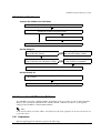
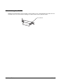
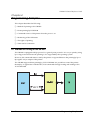
1.9 Part Names
The following view shows the part names of the UB-R02.
Parts side
Antenna
(In the cover)
Cover
Mode Button
Solder side
Connector to Printer
RF module
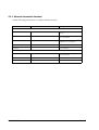
1.10 UB-R02 Initial Setting
The initial setting values of the UB-R02 are as follows.
Parameter
Initial Value
Setting Instructions
Network Mode
AdHoc
Infrastructure/AdHoc
SSID
EpsonNetIBSS
Set this according to the system.
IP-Address
192.168.192.168
Set this according to the system.
Subnet mask
255.255.255.0
Set this according to the system.
Gateway address
0.0.0.0
Set this according to the system.
IP-Address setting
Manual
Auto/Manual
Use WEP key
None
None/64bit/128bit
WEP Key
None
Set this.
Channel
11
1-11 channels. When using Ad-Hoc, set
the channel. When using in the
infrastructure conformation, it is set
automatically.
1-4 System Provisions
Rev. C
UB-R02 Technical Reference Guide
Chapter 2
Installation
This chapter describes the UB-R02 installation. The UB-R02 is an interface board on which is
installed the Radio Frequency module for Epson TM printers. The Radio Frequency module is
installed on the UB-R02 at the factory.
To set up the printer, install the UB-R02 in the Epson TM printer and initialize the UB-R02 to
return it to its default setting. Set the PC to be able to communicate with the UB-R02. Then
change the setting of the UB-R02 using the setting PC. The UB-R02 can be set by using the
dedicated utility TMNetWinConfig.
2.1 Installation Precautions Cautions and Note
CAUTION:
Before installing, disconnect the Power Unit from the TM Printer (as well as turning the
power switch off).
Even when the power switch is off, voltage is still present at some points on the circuit
board. Changing components while the Power Unit is connected can cause damage
to the UB-R02 and the printer.
A grounded wrist strap should be worn during installation to avoid damage from static
electricity.
To avoid damage from static electricity when the unit is removed, place it on an staticsafe surface such as conductive foam.
Protect the unit from vibration and shock that could damage to the unit.
Do not attempt to wire this product other than as described in this document. Improper
wiring could cause damage, fire or explosion.
Never disassemble or modify this product. Tampering with this product may result in
injury, fire, or electric shock.
Note:
Because the default IP address for all the wireless printers is the same, you should power on and configure
only one printer at a time.
Rev. C
Installation 2-1
2.2 Network Equipment
The equipment required depends on the network mode of the wireless LAN. Equipment (except
the printer) for printing only is shown below; prepare the equipment according to the network
mode to be used.
2.2.1 Ad-Hoc Mode
❏ Setting PC
OS: Windows 2000 or XP
A wireless LAN that can connect by the “Ad-Hoc Mode”
The UB-R02 is set to the “Ad-Hoc Mode” by default. So a PC with the wireless LAN
function is needed. When using a PC card for the wireless LAN, install the exclusive
driver for it.
❏ Setting Utility
EPSON TMNetWinConfig Ver.2.00 or later
This utility is an exclusive one to set up the UB-R02. It is compatible with Windows
2000 and XP, and it has no printing function. Download the utility from the Web site
of EPSON and install it in the setting PC. Install it in a PC that manages a network if
necessary.
❏ Network PC
For IEEE 802.11b
Prepare at least one Network PC, which can be the PC for setting.
❏ TM Printer Driver
Advanced Printer Driver(APS) or OPOS
Download the TM Printer Driver from the Epson Web site and install it on the PC on the
network. Also, after connecting the wireless LAN, set the printer port to print by
TCP/IP.
It is possible to connect from devices such as PDAs, but prepare other applications for printing
by users.
2-2 Installation
Rev. C
UB-R02 Technical Reference Guide
2.2.2 Infrastructure Mode
❏ Setting PC
OS: Windows 2000 or XP
A wireless LAN that can connect by the “Ad-Hoc Mode”
The UB-R02 is set to the “Ad-Hoc Mode” by default. So a PC with the wireless LAN
function is needed. When using a PC card for the wireless LAN, install the exclusive
driver to use it.
❏ Setting Utility
EPSON TMNetWinConfig Ver.2.00 or later
This utility is the exclusive one to set the UB-R02. It is compatible with Windows
2000 and XP, and it has no printing function. Download the utility from the Epson
Web site and install it on the setting PC. Install it on the PC that manages a network
if necessary.
❏ Access Point
For IEEE 802.11b Channel:1~11 Prepare at least one
Network PC
An access point is necessary for the “Infrastructure mode.” IEEE 802.11a/b
compatible or IEEE 802.11a/b/g compatible can be used. We recommend an access
point with the SSID function preventing connections from “ANY” and other
equipment, and also an access point that can use several kinds of keys.
❏ Network PC
For Ethernet
Prepare at least one Network PC. The wireless LAN function is not used. It is
possible to use this as the setting PC; however, we recommend the preparation of
another PC for the network because the network setting on the PC must be changed
every time the UBR02A setting is changed.
❏ Network Cable
For Ethernet
Connect the Network PC and the access point.
❏ TM Printer Driver
Advanced printer Driver (APD) or OPOS
Download the TM Printer Driver from the Epson Web site and install it on the PC on
the network. Also, after connecting the wireless LAN, set the printer port to print
with TCP/IP.
Rev. C
Installation 2-3
2.2.3 Network Information Needed
Get the following information to connect with the network.
Item
Intitial Value
Setting Instructions
About the Network
Network Mode
Infrastructure Mode/AdHoc
Mode
SSID
Blank cannot be set. "ANY" is not
recommended
WEP setting
None/64bit/128/bit
128bit is recommended
WEP key
Channel
1-11 Channels
Set to every TM Printer
IP address
Different address is assigned for
each TM printer
Subnet mask
Gateway address
2-4 Installation
Rev. C
UB-R02 Technical Reference Guide
2.3 Outline of the Process
Connect the UB-R02 to the TM Peinter
Unpacking / Preparation
Install the UB-R02 to the TM Printer.
Adjust various settings (If you need)
Print the statatus sheet
Set the setting PC
Set the setting PC and connect with
the UB-R02 by wireless
The setting PC and the UB-R02
are connected by wireless
Set with the wireless LAN setting of
the UB-R02 by the TMNetWinConfig
The wireless LAN setting of
the UB-R02 is changed
Print the statatus sheet
Set the network PC
Confirm that the Network PC and the UB-R02 are connected
by wireless
Test printing
2.4 Connect the UB-R02 to the TM Printer
The UB-R02 is set to the “Ad-Hoc Mode” by default. So if you want to use it in “Infrastructure
Mode,” first connect the UB-R02 in the “Ad-Hoc Mode” and then use the PC to change the
setting of the UB-R02 to “Infrastructure Mode.”
Note:
In the Ad-Hoc Mode, the SSIDs, WEPs, and Channels of all of the equipment on the network must be set
to the same values.
2.4.1 Preparation
Before beginning the installation, prepare the following.
Rev. C
Installation 2-5
•
The TM Printer and Epson power supply
•
The UB-R02
•
A PC that can use a wireless LAN.
•
A network system to which the TM printer will be connected. (For the Ad-Hoc Mode, it
is a PC with a wireless LAN card. For the Infrastructure Mode, it includes the Access
Point or Points and the network.)
Note:
Confirm the SSID, the IP Address, and the network key (WEP) of the LAN environment.
The channels that the UB-R02 can use are 1 through 11. If the channel of the PC or an AP of the LAN
environment is set to 12 or over, it must be changed to 11 or less.
2.4.2 UB-R02 Connection
1. Confirm items in the pack. (See “Unpacking” on page 1-3.)
2. Remove the two screws of the universal interface connector of the TM Printer and connect
the UB-R02, and fix it with two screws.
Connector to the TM Printer
Two fixing screws
3. Set the DIP switch of the TM Printer. The interface of the TM printer must be selected as
“parallel” with the appropriate settings. If a TM printer that can set the reset signal for pin 31
is used, set to “enable.” Refer to the Technical Reference Guide for each TM printer for these
settings for details. Also, set the memory switches according to your needs.
4. Power on the printer. Then, after waiting a little, hold down the mode button on the
interface card for more than 3 seconds. The printer prints the status sheet for the UB-R02.
You can check all setting values necessary for the network connection.
Mode Button
Note:
The printed result (Status sheet) is necessary for later steps.
2-6 Installation
Rev. C
UB-R02 Technical Reference Guide
5. Turn the power switch of the TM Printer on while pressing the Feed button. A status sheet of
the TM Printer is printed.
6. Turn off the TM Printer.
2.4.3 Print the status sheet
Power on the TM Printer, and after waiting 1~2 seconds, hold down the push button of the
UB-R02 for more than 3 seconds by using a clip or penpoint. The parameter sheet of the UB-R02
is printed. The setting value necessary to connect the network can be confirmed.
Push button
❏ An example of a status sheet
**************************************************
MAC:**:**:**:**:**:**
HW/SW:1.00/1.20
WLAN:4.4.1/8.10.1
Necessary item for the network setting
SSID:EpsonNetIBSS
Mode:Ad-hoc
Link:Connect
*1
Channel:11
Tx Rate:Auto
RTS Thresh.:512
AP Density:Low
Auth.:Open System
WEP:OFF
AP:**-**-**-**-**-**
GET IP:Manual
APIPA:OFF
PING:OFF
IP:192.168.192.168
Mask:255.255.255.0
GW:0.0.0.0
Legacy APD:OFF
Factory 1:ON
**************************************************
*1:When the version of H/W is 1.0, Link becomes “Connect” after the UB-R02 can be
connected with the peripheral equipment.
When the version of H/W is 2.0, Link becomes “Connect” automatically after
the AD-Hoc network is built by the UB-R02 even if the UB-R02 cannot be
connected with the peripheral equipment.
Rev. C
Installation 2-7
Note:
The printed parameter sheet is used with the next step.
2.4.4 Default Setting Value
The default setting value of the network relation to the UB-R02 is as follows.
Item
Parameter
Default Value
IP address
xxx.xxx.xxx.xxx
192.168.192.168
Subnet mask
xxx.xxx.xxx.x
255.255.255.0
Gateway address
xxx.xxx.xxx.xxx
0.0.0.0
IP address setting
Auto/Manual
Manual
Comunication mode
Infrastructure/AdHoc
AdHoc
SSID
-
EpsonNetIBSS
UseWEP key
Check/None
None
WEP key
None/64bit/128bit
None
2.5 Setting of the Setting PC
Set the setting PC to be able to connect with the network.
2.5.1 Setting of the Setting PC
Set the LAN setting of the PC to match the parameter sheet printed by following the instructions
in “Print the status sheet” (page 2-7). The items to set are shown below.
Note:
As for the setting method, refer to the manual of the PC or the manual of the wireless LAN card.
❏ Network mode (Ex : AdHoc mode)
❏ SSID (Ex : EpsonNetIBSS)
❏ WEP (Ex : None)
❏ IP address (Ex :192.168.192.2)
(Don’t set an address that is the same as the IP address of the printer.
Example : When the IP address of the printer is 192.168.192.168, set the IP address of the PC
to 192.168.192.2. Never use the same address: 192.168.192.168.)
❏ Channel (Ex : 11ch)
Note:
During this step, the setting PC and the TM printer can communicate. When setting the communication,
power on the TM printers one by one. Otherwise, when plural TM Printers using the default settings are
powered on, the printer being used is not known.
2-8 Installation
Rev. C
UB-R02 Technical Reference Guide
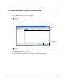
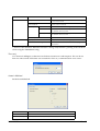
2.5.2 Setting the Wireless LAN by the TMNetWinConfig
1. Turn on your printer.
2. Run “TMNetWinConfig“ on the setting PC.
Note:
If the utility hasn’t been installed on the setting PC, install it now.
3. Confirm that the printer is shown on the list view.
The printer is displayed in the list.
Configuration
button
Note:
If the printer is not shown on the list view, See ““POSPrinter” is not shown in the TreeView of
the TMNetWinConfig.” on page B-1.
4. Select the printer from the list view. Click the “configuration“ button.
Rev. C
Installation 2-9
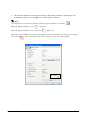
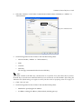
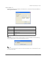
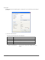
5. The Network Interface Card Properties dialog is displayed. Select the “Information” tab.
Confirm the electric wave strength level of the “Signal Condition.”
Note:
We recommend to use under the condition which the Signal Condition is “Excellent”
When the Signal Condition is “poor”
.
, (page B-1.)
When the Signal Condition is “No Connection”
, (page B-1.)
When the version of H/W is 2.0 and the communication mode is the AD-Hoc, the electric wave strength
level is always
2-10 Installation
. Refer to “Print the status sheet” (page 2-7) as for the version of H/W.
Rev. C
UB-R02 Technical Reference Guide
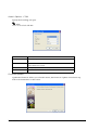
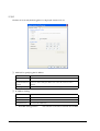
6. Select the “Wireless” tab. Set the Communication Mode (Network Mode) to “AdHoc” or
“Infrastructure.”
Set to Infrastructure
7. Set following items for the wireless LAN installed in the printer.
•
Network mode (“AdHoc” or ”Infrastructure”)
•
SSID
•
Channel
•
WEP Key
We strongly recommend 128 bit for the WEP Key.
Note:
If you make a mistake in the WEP key, communication is not possible. Even if the Status sheet is printed,
the WEP key is not understood. When the WEP key is not understood, reset the UB-R02. After setting the
UB-R02 to the default setting, set it again once more from the section on preparing a host PC on page 2-5.
8. Click “TCP/IP” tab.
9. Set following items for the wireless LAN installed in the printer.
Rev. C
•
Method for specifying the IP address
•
IP address setting (IP address, Subnet Mask, Default gateway)
Installation 2-11
10. Click "OK" and the property of the network I/F is closed. And the setting of the TM printer
is updated. Then the printer that was displayed in the list viewdisappears because the
connection with the setting PC is stopped by changing the network setting of the TM Printer.
2.5.3 Print the status sheet
Print the parameter sheet of the TM Printer and confirm that the setting contents are reflected.
Refer to “Print the status sheet” (page 2-7) for the printing method.
2.6 Setting of the Network PC
2.6.1 Confirmation of the connection
Confirm that the TM Printer can be connected with the network environment by using the
network PC.
Note:
Refer to the manual of the PC or the manual of the wireless LAN card for the setting method of the PC.
When TMNetWinConfig is installed on the PC on the network, confirm the electric wave
condition in the "Information" of the "Network Interface Card Properties.
Note:
We recommend to use it when the electric wave strength level is “Excellent”
.
When the version of H/W is 2.0 and the communication mode is the AD-Hoc, the electric wave strength
level is always
2-12 Installation
. Refer to “Print the status sheet” (page 2-7) as for the version of H/W.
Rev. C
UB-R02 Technical Reference Guide
2.6.2 Downloading of the Printer Driver
Download the printer driver for printing from the web site and install it on the PC for printing
on the network. The Epson Advanced Printer Driver (APD) and OPOS can be downloaded from
the web sites listed on page 1-3. Refer to the Epson Advanced Printer Driver manual for details
on using the APD.
2.6.3 Setting up the Driver
Install a printer driver such as OPOS, JavaPOS, or APD, and confirm that it is possible to print
normally.
Note:
You should be able to obtain the correct driver from an Epson web site (see page 1-3) or your dealer.
2.6.4 Printout Test
The printout test is done from the PC on which the TM printer driver is installed.
2.6.4.1 APD
Refer to the APD manual for the details of installing and using the APD.
1. Confirm that the APD is installed.
2. Confirm that the module and the TCP/IP Driver are installed for the printer being used. If it
is not installed, install the APD.
Note:
Sometimes the TCP/IP Driver is not installed even if the module of the printer is installed. In this
case, reinstall the APD.
3. Open the property of the TM printer on which the UB-R02 is installed in the OS printer
setting.
4. Select "EPSON TM/BA/EU Printer Port Ver3" in the Port-"Printer Port Addition"
5. Set the IP address of the printer. After that, restart according to the message on the screen.
6. Do the APD test print.
2.6.4.2 OPOS Notes
Note:
Set the IP address of the printer by using the Setup utility for OPOS.
Note:
Print by using the CheckHealth function of OPOS.
Rev. C
Installation 2-13
2.7 Initializing the UB-R02
Holding the mode button while turning on the printer power, and continuing to hold it for five
seconds, causes all of the internal settings to return to their factory default values.
Mode Button
2-14 Installation
Rev. C
UB-R02 Technical Reference Guide
Chapter 3
Utilities
3.1 Setting the TCP/IP Protocol in Your Operating System
To set the IP address, you need to install the TCP/IP protocol in your operating system. How to
set the TCP/IP protocol is explained for Windows 2000 and Windows XP.
3.1.1 Windows 2000
1. Double-click the Network and Dial Set Up icon in the Control Panel; then click Local Area
Connection Status.
2. Click Properties and check whether the Internet Protocol (TCP/IP) check box is checked. If
not, click the check box.
Note:
After the TCP/IP is installed, restart your computer and move on to the Installing TMNetWinConfig
section.
Rev. C
Utilities 3-1
3.1.2 Windows XP
1. Click the Network and Internet Connections icon in the Control Panel; then click
Network Connections.
2. Double-click the Local Area Connection icon. The Local Area Connection Status dialog
is displayed.
3. Click Properties and check whether the Internet Protocol (TCP/IP) check box is checked. If
not, click the check box.
Note:
After the TCP/IP is installed, restart your computer and move on to the Installing TMNetWinConfig
section.
3-2 Utilities
Rev. C
UB-R02 Technical Reference Guide
3.2 TMNetWinConfig
3.2.1 Preparation
To find out how to obtain the utility, see “Environments for Setup Utility” on page 1-3.
3.2.2 Install
3.2.2.1 Installation Environment
Your computer should meet the following conditions:
❏ The hard disk must have unused memory of 3 MB or more.
❏ The operating system must be one of the following:
Windows 2000 or Windows XP.
❏ IBM PC/AT compatible with the operating systems mentioned above.
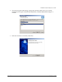
3.2.2.2 Windows 2000 or Windows XP
1. Unzip the file and start Setup.exe.
2. The Welcome dialog is displayed. Click Next.
Rev. C
Utilities 3-3
3. The License Agreement dialog is displayed. After confirming the contents, click Yes.
4. The Choose Destination Location dialog is displayed. Select the folder where you want the
installation to take place and click Next. By default, “C:\Program Files\EPSON\TMNet
WinConfig V2\” is selected.
3-4 Utilities
Rev. C
UB-R02 Technical Reference Guide
5. The Select Program Folder dialog is displayed. Select the folder where you want the
installation to take place and click Next. By default, “EPSON TMNet WinConfig V2” is
selected.
6. When the installation is finished, click Finish.
Rev. C
Utilities 3-5
3.2.3 Operating
CAUTION:
Be sure not to turn off the printer or send printing data to the printer while setting. Do not
use the same IP address as that of any other network device or PC.
3.2.3.1 IP Address Setting
Here, as an example, setting the IP Address in Windows XP is explained.
1. Make sure Windows is running, the UB-R02 is connected to the printer, and the printer is
turned on.
2. Click Start, point to All Programs, point to EPSON TMNetWinConfig V2; then click
TMNetWinConfig.
3. Click the printer where you want to set the IP address, and then click the Configuration
button. (You might wait for 10 seconds or more to view the UB-R02 over the network on
your screen.)
Note:
If you have connected more than one printer to the network and do not know for which printer you want to
set the IP address, you can check the printer by finding out the MAC address of the UB-R02. The MAC
address can be found on the status sheet. For printing the status sheet, refer to 2.4.3.
3-6 Utilities
Rev. C
UB-R02 Technical Reference Guide
4. Click the TCP/IP tab. Under Method for specifying the IP address, select one of the
following: Automatic, DHCP, or Manual.
Note:
The UB-R02 cannot select BOOTP or RARP.
When using DHCP, select Automatic. DHCP is grayed out, but it can be used.
5. Assign the IP address, the Subnet mask, and the Default gateway. If you use DHCP to
acquire an IP address, you cannot assign these items. Ask your administrator for the IP
address and the Default gateway to be set.
CAUTION:
Be sure that the Set using PING box is turned on if a setting by PING or ARP command is
permitted.
When executing setting by ARP/PING, the “Set using PING” checkbox is unchecked
automatically.
Note:
The default IP address is 192.168.192.168. and the default Subnet mask is 255.255.255.0, and the default
gateway is 0.0.0.0.
If a server or router acts as a gateway, type the gateway address.
Rev. C
Utilities 3-7
6. Click the OK button.
7. Click the OK button again to be sure.
8. Click the OK button again.
Note:
The UB-R02 cannot use the Password function.
9. When the message “Transmission is complete” appears, click OK.
CAUTION:
After clicking OK, you must not turn off the printer while the new settings are being sent
to the UB-R02.
Note:
To get the information for the UB-R02 for the other segments, refer to 3.2.4.
3-8 Utilities
Rev. C
UB-R02 Technical Reference Guide
3.2.4 Functions
This section describes the functions, including options of the TMNetWinConfig. The main
dialog box is shown below.
Item
Tree view
List view
.
Item
Explanation
Tree view
The tree structure indicates the printer list.
Item
You can change the order by clicking on an item. You can also adjust
the viewing size of the item by dragging a dividing line between the
items.
List view
Indicates the information for the UB-R02.
Configuration
Select the Model Name and then click this button. The setting window of
the TMNetWinConfig appears.
Note:
The UB-R02 cannot use the Launch Browser button.
3.2.4.1 Menu Bar
The table shows each item and its function.
Menu
Sub Menus
Explanation
Device
Configuration
Start the setting of the UB-R02 selected
Launch Browser
The UB-R02 cannot use this.
Quit
Close the TMNetWinConfig
Refresh
Find the printers and update the list to show the latest
information.
View
Rev. C
Utilities 3-9
Menu
Sub Menus
Explanation
Tool
Timeout
Set the time-out for data transmission and reception
to 2 to 120 seconds.
Search Method
Set the search method.
Search Options
Help
IP
Set the Search Options setting used UDP/IP.
IPX
Set the Search Options setting used IPX.
The UB-R02 cannot use this.
COM (*)
Set the Search Options setting used COM.
The UB-R02 cannot use this.
Firmware Update
Update the firmware.
Help Topics
Indicates the TMNetWinConfig help.
About TMNetWinConfig
Indicates the version information and copyright
information.
Don’t use this function. While this function is being used, Windows printing cannot be done
while using the TMNetWinConfig.
(*)
Time-out
Use Time-out setting to set the time-out for data transmission and reception. This can be set
from 2 to 120 seconds. If the time-out exceeds the value set, a communication error occurs.
Search Method
Set the Search Method.
Item
Explanation
Select All
All selectable Search methods are set.
Select Individually
Selectable Search methods are set individually.
3-10 Utilities
Rev. C
UB-R02 Technical Reference Guide
Search Options - IP
Specify the Searching network address and subnet mask. A maximum of 20 network addresses
can be registered to the list.
Item
Explanation
Search specified
address
The specified address is searched.
Network Address
Set the network address.
Subnet Mask
Set the subnet mask.
Add
Click Add after entry in Network Address and Subnet Mask; the address
is added to the list.
Remove
Select the address from the list and click Remove; the address is
deleted.
Note:
Input 0 as the local Network address. When the address is specified to anything except 0, the following
dialog is displayed. When you click OK, the local address is set to 0.
Note:
“0.0.0.0” and “255.255.255.255” cannot be set as the Network address. Also, “255.255.255.255” cannot
be set as the Subnet mask.
Rev. C
Utilities 3-11
Search Options - COM
Specify the Searching com port.
Note:
Don’t use it with the UB-R02.
Item
Explanation
Port
Set the COM port number.The COM port numbers that can be set are 1256.
Baud (bps)
Set the baud rate.The baud rate that can be set is either of 9600/14400/
19200/38400/57600/115200.
Parity
Set the parity. Set to either of None, ODD or EVEN.
Flow Control
Set the flow control. Set to either of None, RTS/CTS or DTR/DSR.
Firmware Update
Update the Firmware. When you select this menu, the Firmware Update wizard starts up.
Follow the instructions on the screen.
3-12 Utilities
Rev. C
UB-R02 Technical Reference Guide
Help Topics
Help for the TMNetWinConfig is displayed.
About TMNetWinConfig
The version information of the TMNetWinConfig is displayed. When clicking the mouse on the
left in the dialog or pressing [Enter] key or [ESC] key, the dialog is closed.
3.2.5 Settings
Start up the TMNetWinConfig, and click the printer you want to set, and then click the
Configuration button. The settings dialog is displayed. The UB-R02 current setting contents can
be confirmed and be changed.
Setting contents of each head are explained below.
Rev. C
Utilities 3-13
Information
Click the Information tab and dialog below is displayed. You can confirm the present setting of
the UB-R02.
❏ Network-Card Information
Information about the Network-Card is displayed.
Item
Explanation
MAC Address
MAC Address is displayed.
Hardware Version
Hardware Version is displayed.
Software Version
Software Version is displayed.
Model Name
Model Name of the TM printer is displayed.
Location
The UB-R02 cannot use this.
•
Return to Default button
3-14 Utilities
This returns the setting of the UB-R02 to the factory
setting.
Rev. C
UB-R02 Technical Reference Guide
❏ Path Information
Information about Path Information is displayed.
Item
Explanation
Search Path
The protocol used by the Search and the protocol detected by the
Search is displayed.
❏ Wireless Information
Information about Wireless communication is displayed.
Item
Explanation
Communication
Standard
The IEEE communication standard type of the wireless LAN is displayed.
Communication
Mode
Communication Mode (Network Mode) (Infrastructure or Ad Hoc) is
displayed。
SSID
The wireless Service set of the print server is displayed.
Channel
The channel of the wireless LAN is displayed.
Transmission Rate
The transmission rate of the wireless LAN is displayed.
Signal Condition
The signal condition is displayed an the icon.
(The communication speed is a standard and it is not be guaranteed.)
Excellent
This shows that about 11Mbps is possible.
Good
This shows that 5.5 or 2Mbps is possible.
Poor
This shows that 1Mbps is possible.
No Connection: Communication may be impossible.
Unknown
:Confirm the setting once again.
?
:This is displayed when the version of H/W is 2.0
and the communication mode is the AD-Hoc.
Note:
When any of the Wireless Information cannot be acquired, Unknown is displayed.
•
Rev. C
Refresh button
The Wireless Information is updated with the latest
information.
Utilities 3-15
Wireless
Click the Wireless tab and the dialog below is displayed. Set the setting of the Network Mode,
SSID, and WEP.
Note:
The SSID cannot be set to “ “ (blank).
❏ Basic Settings
Set the basic settings of the Wireless communication.
Item
Explanation
Communication
Mode
Set the Communication Mode (Network Mode) of the wireless LAN to
either the infrastructure mode or the Ad-Hoc mode.
SSID
Set the wireless the Service Set (SSID) belonging to the print server. When
clicking the Browse button, the list of SSID confirmed at present is
displayed. You can select the SSID and set it, too.
Channel
If the Network mode is in Ad-hoc mode, sets the channel in the list.
3-16 Utilities
Rev. C
UB-R02 Technical Reference Guide
❏ Use WEP Key
When using the WEP Key, check the checkbox and set the following item
Note:
When clicking the “Use WEP Key” checkbox, WEP becomes on and Authentication Method of
Advanced Settings is set to “Shared Key” automatically.
When the “Use WEP Key” checkbox is not checked, WEP becomes off and Authentication Method of
Advanced Settings is fixed to “Open System.”
Rev. C
Item
Explanation
Use WEP Key
Check
WEP key: ON, Authentication Method of Advanced Settings: “Shared Key”.
Clear
WEP key: OFF, Authentication Method of Advanced Settings: “Open
System”.
WEP Key Length
Set the length of the WEP key to either 64 bits or 128 bits.
WEP Key Input
Method
Set the character of the WEP key to either Hexadecimal or ASCII.
WEP Key 1/2/3/4
Input the WEP key.
When setting the WEP key Input Method to ASCII, the optional character
string can be input. When setting the WEP key Input Method to Hexadecimal,
only the letters of “0”-”9”, “a”-”f”, “A”-”F” can be input.
Also, when setting the WEP Key Length to 64 bits, always input 5 letters by the
ASCII character, or always input 10 digits by the Hexadecimal. When setting
the WEP Key Length to 128 bits, always input 13 letters by the ASCII
character, or always input 26 digits by the Hexadecimal.
Active WEP Key
Select the WEP key for using from 1-4.
Utilities 3-17
•
Advanced Settings button
The Wireless Advanced Settings dialog is displayed; set
the following detailed items.
❏ Advanced Settings
Item
Explanation
Transmission Rate
Set either Automatic/1Mbps/2Mabps/5.5Mbps/11Mbps.
Authentication
Method
Set either Shared key/Open System.
❏ Power Management Setting
Note:
The UB-R02 does not support it.
Item
Explanation
Enable the power
management
function
Set the Disable/Enable of the Power management.
3-18 Utilities
Rev. C
UB-R02 Technical Reference Guide
❏ RTS/CTS Threshold Setting
Item
Explanation
Set RTS/CTS
handshake control
Set the Disable/Enable of the RTS/CTS handshake control.
RTS/CTS Threshold [02347]
Set the value, 0-2347.
❏ Roaming Setting
Item
Explanation
Enable the roaming
function
Set the Disable/Enable of the AP Density.
The UB-R02 cannot use this.
AP Density
Set the access point density to Low, Medium, or High.
❏ Fragment Threshold Setting
Rev. C
Item
Explanation
Set fragment
threshold
Set the Disable/Enable of the Fragment threshold.
The UB-R02 cannot use this.
Fragment Threshold
[256-2346]
Set the value of 256-2346.
The UB-R02 cannot use this.
Utilities 3-19
TCP/IP
Click the TCP/IP tab; the dialog below is displayed. Set the TCP/IP.
❏ Method for specifying the IP address
Item
Explanation
Method
Set either Automatic/Manual.
Set using Automatic
Private IP Addressing
(APIPA)
Set the Disable/Enable of the Automatic Private IP Addressing (APIPA).
function. When setting the Method to Automatic, this item is set to
Enable.
Set using PING
Set the Disable/Enable of the IP address setting by PING.
❏ IP Address Setting
Item
Explanation
IP Address
Set the IP Address.
Subnet Mask
Set the Subnet Mask.
Default Gateway
Set the Default Gateway.
•
Extended Settings button
3-20 Utilities
This function cannot be used with the UB-R02.
Rev. C
UB-R02 Technical Reference Guide
Chapter 4
Programming Samples
This chapter describes the following:
❏ Method of printing to the UB-R02
❏ Direct printing by PORT9100
❏ Commands sent to a TM printer when the power is on
❏ Monitoring of the ASB status
❏ The rights of printing
❏ Time-out for connection
4.1 Method of Printing to the UB-R02
The UB-R02 is equipped with lpr protocols as general print protocols. It is easy to print by using
lpr or ftp protocols because the printing is also supported by the operating system.
However, the command statuses sent by the printer are ignored because the printing by lpr or
ftp applies only to output of the printer.
The UB-R02 supports direct printing by TCP PORT9100. It is possible to control the printer
directly by an application with the ESC/POS commands through writing and reading to the
TCP PORT9100.
Rev. C
Programming Samples 4-1
4.2 Direct Printing by PORT 9100
4.2.1 For Windows Console
The program is a sample of printing “EPSON UB-R02” to a TM printer with the UB-R02 from the
Windows shell, through the ethernet connection.
/* TCP9100 programming sample for Win32
* HOW TO BUILD
* cl tcp9100.c wsock32.lib
*/
#include <stdio.h>
#include <winsock.h>
int main(int argc, char* argv[])
{
WSADATA data;
SOCKET sock;
struct sockaddr_in addr;
if (argc != 2) {
printf("usage: tcp9100 IP_ADDRESS\n");
exit(1);
}
/* Initialize windows sockets */
WSAStartup(0x0101, &data);
/* Create sockets */
if ((sock = socket(AF_INET, SOCK_STREAM, 0)) == INVALID_SOCKET) {
fprintf(stderr, "Error socket(): %d\n", WSAGetLastError());
exit(1);
}
/* initialize the parameter */
memset(&addr, 0, sizeof(addr));
addr.sin_family = AF_INET;
addr.sin_port = htons(9100);
addr.sin_addr.s_addr = inet_addr(argv[1]);
/* connect */
if (connect(sock, (struct sockaddr*)&addr, sizeof(addr)) < 0) {
fprintf(stderr, "Error connect(): %d\n", WSAGetLastError());
exit(1);
}
printf("connected\n");
/* send data */
send(sock, "\x1b@EPSON\x0a", 8, 0);
/* close socket */
closesocket(sock);
return 0;
}
4-2 Programming Samples
Rev. C
UB-R02 Technical Reference Guide
4.2.2 For Linux
The program is a sample of printing “EPSON UB-R02” to a TM printer with the UB-R02 from the
Windows shell, through the ethernet connection.
/* TCP9100 programming sample for linux
* HOW TO BUILD
* cc tcp9100.c
*/
#include <stdio.h>
#include <string.h>
#include <sys/types.h>
#include <sys/socket.h>
#include <netinet/in.h>
#include <netdb.h>
int main(int argc, char* argv[])
{
int sockfd;
struct sockaddr_in addr;
if (argc != 2) {
printf("usage: tcp9100 IP_ADDRESS\n");
exit(1);
}
/* create socket */
sockfd = socket(AF_INET, SOCK_STREAM, 0);
if (sockfd < 0) {
perror("socket()");
exit(1);
}
/* initialize the parameter */
memset(&addr, 0, sizeof(addr));
addr.sin_family = AF_INET;
addr.sin_port = htons(9100);
addr.sin_addr.s_addr = inet_addr(argv[1]);
/* connect */
if (connect(sockfd, (struct sockaddr*)&addr, sizeof(addr)) < 0) {
perror("connect()");
}
printf("connected\n");
/* send data */
send(sockfd, "EPSON UB-R02\x0a", 13, 0);
/* close socket */
close(sockfd);
return 0;
}
Rev. C
Programming Samples 4-3
4.3 Monitoring of the ASB status
The UB-R02 monitors the ASB statuses transmitted from TM printers to control the printer
statuses from host computers. The printer can know the statuses remotely using the
TMNetWinConfig.
If the printing data includes commands that disable the ASB such as ESC @ and GS a 00h, the
ASB status from the TM printer will not be transmitted afterward when the printer status is
changed and the UB-R02 cannot monitor the status of the TM printer.
To monitor the printer status, when there is a command that disables the ASB in a data string
sent by an application to the TM printer, transmit a command that enables the ASB.
4.4 The Priorities of Printing
The UB-R02 permits up to 2 requests of connecting regardless of the lpr/ftp/port9100 protocol.
Printing by the TM printer is given the first priority. Data transmission is blocked for other
requests until the first connection is closed (explicit close or close by time-out).
4.5 Time-out for Connection
If there is no data transmitted from the host for 5 minutes, regardless of the protocol, port9100,
the UB-R02 closes the connection. To continue the connection, the host needs to send the UDP
command explicitly.
4-4 Programming Samples
Rev. C
UB-R02 Technical Reference Guide
Chapter 5
Specifications
5.1 Structure
The UB-R02 can be installed in TM series printers as an interface board to provide Wireless
Ethernet (IEEE802.11b) communications.
Access Point
HOST PC
UB-R02
EPSON PRINTER
5.1.1 Printer Connection
The interface board can be installed in TM series printers that support the universal interface
board system.
5.1.2 Line Display Connection
When the UB-R02 is connected, the DM connector on the TM unit cannot be used. Refer to the
Supported TM Printers section in Chapter 1.
Rev. C
Specifications 5-1
5.2 Features
5.2.1 Overview
❏ Wireless Ethernet (Compatible with IEEE802.11b standards)
❏ Complies with TCP/IP protocol (LPR and socket communications)
❏ The interface board system can be connected to a variety of TM printers with the universal
interface
❏ Dimensions: 95 × 86 × 28 mm {3.74 × 3.38 × 1.10"}
5.2.2 Printing Functions
❏ Printing by standard protocols (printing of network objects through a device driver
Printing Protocol
OS
OS Standard
Additional
Microsoft Windows NT4.0/2000/XP
LPR
-
Printing from Unix
LP, LPR
-
❏ Socket printing by unique socket communications (port 9100 for OPOS)
❏ Supports OPOS/APD/JavaPOS
5.2.3 Functions to Monitor Settings
❏ IP address setting by Using PING
❏ Supports DHCP
❏ PING response
❏ Status printing function
5.2.4 Maintenance Functions
❏ Firmware can be updated through wireless communication.
5-2 Specifications
Rev. C
UB-R02 Technical Reference Guide
5.3 Hardware Specifications
5.3.1 Physical communications standard:
Wireless Ethernet (IEEE 802.11b)
5.3.2 External size
1) Dimensions: 90 × 86 × 28 mm {3.74 × 3.38 × 1.10"}
2) External appearance drawing
95mm
28mm
86mm
5.3.3 Mode Button
Mode button (push switch) is provided which performs following functions
1. Setting initialization
Holding the mode button while turning on the printer power and continuing to hold it for
five seconds causes all of the internal settings to return to their factory default values.
2. Status sheet printing
Holding the mode button for three seconds while the printer is ready to print causes the
module’s internal setting parameters to be printed out.
Rev. C
Specifications 5-3
5.4 Software Specifications
5.4.1 Basic Communications Protocols
Protocol
Application
IP, ARP, ICMP, UDP, TCP
Basic communications protocols for various functions (used by the
following higher-level protocols)
5.4.2 Printing Communications Protocols
Protocol
Application
LP, LPR
Transfer printing data
TCP Socket Port
Transfers printing data and printer status by direct socket
communications (bi-directional)
5.4.2.1 LP, LPR
❏
Job deletion:
not supported
❏
Banner printing:
not supported
5.4.2.2 Socket Communications
❏
Port type:
TCP comm. port for direct printing
❏ Port number:
9100
❏
bi-directional
Port communication direction:
5.4.3 IP Address Assignment Method
The UB-R02 supports the following method for IP address assignment.
Protocol
Application
DHCP
Acquire IP address
manual setting
Uses the internal set parameters
5.4.3.1 IP Address Acquisition by DHCP
❏ Items to acquire:
IP address, subnet mask, gateway address
5.4.3.2 Manual Setting
The UB-R02 interface board operates in accordance with the internal parameter settings.
5-4 Specifications
Rev. C
UB-R02 Technical Reference Guide
5.4.4 Internal Settings
5.4.4.1 Item List
Item
Parameter
Initial value
IP address
xxx.xxx.xxx.xxx
192.168.192.168
Subnet mask
xxx.xxx.xxx.x
255.255.255.0
Gateway address
xxx.xxx.xxx.xxx
0.0.0.0
IP address setting
Auto/Manual
Manual
Network Mode
Infrastructure/
AdHoc
AdHoc
SSID
-
EpsonNetIBSS
WEP setting
None/64bit/128bit
None
WEP Key
-
None
5.4.4.2 Internal Parameter Setting Methods
❏ Using the TMNetWinConfig (Version 2.0 or later)
❏
Using PING commands (only to set IP address)
5.4.4.3 Set the IP Address using PING
This function is available when it has been enabled.
The setting can be made from a host in the same segment as the module.
The host must support both PING commands.
The new IP address takes effect when the module responds to the PING command.
Example: using Windows
arp -s 123.456.789.123 00-00-48-06-00-01
ping 123.456.789.123
5.4.4.4 How to check the Mac Address
The Mac address of the UB-R02 can be checked by printing a status sheet
5.4.5 Start up period
To initialize UB-R02 and network connection, there is start up period after the power ofthe
printer is turned on or UB-R02 is reset. The start up period takes around 10 seconds. During this
period, all network functions do not work.
5.4.6 Version Upgrading
The module can upgrade its own firmware over the network.
5.4.6.1 Supported protocol
❏ TFTP
Rev. C
Specifications 5-5
5.4.6.2 Upgrade Methods
❏ Using TFTP command (Windows NT 4.0/2000/XP)
❏ Using TM NetWinConfig.
5.5 Environmental Specifications
Temperature:0 to 50° C {32 to 122° F}
Humidity:10 to 90% RH (non-condensing)
5.6 Storage Conditions
Temperature:
-10 to 50° C {14 to 122° F}
Humidity:10 to 90% RH (non-condensing)
5-6 Specifications
Rev. C
UB-R02 Technical Reference Guide
Appendix A
Wireless LAN Network Composition
1.1 Network mode
1.1.1 Infrastructure Mode
This is a method for connecting to an existing wired network using an access point. If multiple
access points are in the same proximity, set their channels at least five channels apart. For setting
the access point, see the manual for the access point.
Access Point
1.1.2 Ad Hoc Mode
A network connection between personal computers and printers that have a wireless LAN
function is called an “Ad Hoc Mode.” Each piece of equipment can be connected without using
an access point.
This product supports the IBSS AdHoc mode.
To use the Ad Hoc connection, set the network name [SSID], the network key, and the channel of
each device to the same setting.
Rev. C
Wireless LAN Network Composition A-1
1.2 Wireless LAN Use
The Radio Frequency module that can be installed to this product uses the IEEE 802.11b
standard and cannot communicate with equipment using IEEE 802.11a and IEEE 802.11g.
The distance between the communicating wireless LAN equipment must be 25 meters or less,
but the distance of possible communication depends on the environment. Also, the
communication speed sometimes declines at longer distances.
The wireless LAN can be set to any one of 11 channels, but when another wireless LAN network
is using a channel with a similar number, it sometimes interferes. Therefore, set the two
networks to channels that are at least 5 channels apart.
Place the access point, the built-in wireless LAN system, and the printer separate from other
electronic devices. Specifically, equipment such as microwave ovens that emit high frequency
energy can cause interference. If this happens, move the wireless equipment or the interfering
equipment so that there is no more interference.
Radio and other broadcasting equipment can also interfere with the wireless communication. If
this happens, move the access point and the printer away from the interference.
Because Bluetooth and the wireless LAN use the identical frequency band (2.4GHz), signal
interference sometimes occurs when they are used close together. Separate them by more than
10 meters.
2.Wireless LAN Security
2.1.1 Security of a wireless LAN
Why does a wireless LAN need a security function?
A wireless LAN is designed to be constructed easily without the labor of wiring, In the wired
LAN environment, because the communication flows through a network cable, the cable must
be connected physically to tap or monitor the communication contents and/or tamper with the
data. But with wireless, the communication is broadcast and susceptible to interception.
Communicating on a wireless network without using security is the same as leaving your house
without locking the door. Therefore, we recommend using wireless security options. A wireless
LAN needs better security measures than a wired LAN does.
What kind of security functions does the wireless LAN have?
To prevent above-mentioned problem, the wireless LAN of the IEEE802.11 method is provided
with the security functions described below, which can be set easily by the developer and the
end user.
Not setting security at all with a wireless LAN is the same as going out without locking the door
of your house. These security functions attempt to prevent your data from being monitored or
tampered with by a third party.
For increased wireless security, you can use such methods as a Radius server and Internet
Protocol Security (IPSec).
A-2 Wireless LAN Network Composition
Rev. C
UB-R02 Technical Reference Guide
2.1.2 Security Function Overview
SSID (Service Set Identifier)
The SSID (Service Set ID) is a unique name that is specified to distinguish a network from other
networks, and it is set to the same value for all parts of the network, such as the wireless LAN
terminal of the access point and the UB-R02. Usually, only wireless LAN terminals that are set to
the same SSID can communicate with each other. A wireless LAN terminal set to “ANY” or a
blank SSID can connect even if it has a different SSID. When the access point has a security
function to refuse communication from equipment set to “ANY” or blank, use the security
function to prevent a connection from a third person.
A third person can know the SSID easily because the access point sends information regularly.
Some access point models can prevent sending the information, and using this function
decreases this danger. We recommend using an access point having this security function.
Moreover, we recommend setting an optional SSID character string that can not be guessed by a
third person.
WEP (Wired Equivalent Privacy)
WEP is a function to encrypt wireless data, and it is set for all parts of the network, such as the
wireless LAN terminal of the access point and the UB-R02. The WEP is not automatically turned
on, so be sure to set it to be on. Also, if you have a choice to set the WEP key to 128 bits or 64 bits,
select 128 bits to make it more secure.
MAC (Media Access Control) Address Filtering
MAC is the function that prohibits connections to an access point except by equipment that has
the subscribed MAC address.This helps invasion prevention but has no effect in wiretap
prevention. We recommend using MAC and WEP together because there is always a possibility
that the MAC address has been wiretapped by a dedicated tool.
Note:
Just as you can protect your house better with two locks instead of one, you can protect your network
better by using more than one security feature. We recommend using all three of the above functions.
Rev. C
Wireless LAN Network Composition A-3
3. Q&A
Q1. Why is this security necessary? Why is security discussed only for the wireless LAN?
A1. In the wired LAN environment, because the communication flows through a network cable,
the cable must be connected physically to tap or monitor the communication contents and/or
tamper with the data. But with wireless, the communication is broadcast and susceptible to
interception. Communicating on a wireless network without using security is the same as
leaving your house without locking the door. Therefore, we recommend using wireless security
options.
Q2. Is it necessary to set the security in order to use the network?
A2. You can use a wireless network without using security; however, it is left open for people to
see the information and/or tamper with the servers.
Q3. What happens if security is not used?
A3. Without security, there is a possibility to suffer much damage, such as the following:
Personal information such as ID, passwords, credit card numbers, and the contents of e-mail can
be stolen.
Fake information can be sent from your network.
Your data and system can be destroyed by an electronic virus
Q4. Why isn’t the security function set before the product is shipped from EPSON?
A4. The identical cipher key must be set for the wireless LAN card and the access point.
However, because this equipment is often bought separately by users, the security cannot be set
beforehand. Also setting the same cipher key for all equipment means that the effect of
encryption is lost.
Therefore, we suggest that user sets the security according to the environment used.
Q5. What kind of security functions are available?
A5. For the easy setting of the security function, set the SSID, WEP, and the MAC address. For
increased security, you can use such methods as a Radius server and Internet Protocol Security
(IPSec).
Q6. What kind of access point equipment should be chosen?
A6. IEEE 802.11b, IEEE 802.11a/b, or IEEE 802.11a/b/g specifications are required for the access
point. It can use channels 1 through 11. For security, we recommend the model that has
following functions: (1) the function that can refuse communication from equipment set to
“ANY” or blank, (2) the function that can stop the broadcast of the SSID, (3) the function to use
several kinds of the WEP key.
A-4 Wireless LAN Network Composition
Rev. C
UB-R02 Technical Reference Guide
Q7. Why is 128 bits better than 64 bits?
A7. When the WEP key is set to 64 bits, the encryption is done by a combination of five
characters; therefore, the communication contents can be deciphered easily by trying all of the
combinations of five characters. 128 bits takes more time to decipher than 64 bits, so the security
is raised.
Q8. Does using encryption slow down data transfer?
A8. Yes, however, it is not by a noticeable amount.
Q9. Do these security functions guarantee the safety of the data and the network?
A9. Using the available security functions appropriately makes your network safer just as
locking the door when going out makes your house safer. However, these functions do not
guarantee 100% security. We recommend doing what you can to maintain security, such as
changing the WEP key regularly.
Rev. C
Wireless LAN Network Composition A-5
A-6 Wireless LAN Network Composition
Rev. C
UB-R02 Technical Reference Guide
Appendix B
FAQ
Problems When Using the TMNetWinConfig
Q 1. “POSPrinter” is not shown in the TreeView of the TMNetWinConfig.
The TMNetWinConfig does not recognize the UB-R02.
A 1.1
The UB-R02 is out of the wireless communication range.
Move the UB-R02 near the AP or PC.
A 1.2
The TM printer is turned off.
Turn on the TM printer.
A 1.3
The UB-R02 is not connected correctly.
Confirm that the UB-R02 is connected correctly.
A 1.4
There are problems with the AP or network cable.
Confirm that the AP is on and that the network cable is not unplugged or cut.
A 1.5
The PC or network settings differ from those of the UB-R02.
See “Setting the wireless LAN parameters for the UB-R02 is not possible.” (page B-2) or
“Connection with network is not possible.” (page B-3).
Q 2. The Information-Signal Condition of the TMNetWinConfig is “No Connection.”
Note:
When the version of H/W is 2.0 and the communication mode is the ad-hoc,
electric wave condition is not detected in this mode.
is appears because the
Communication was possible, but communication is impossible after the latest information is
updated.
The Signal Condition displays the strength level of the signal as one of four levels, “Excellent,”
“Good,” “Poor,” and “No connection.” The signal can always change. Press the Refresh button
to confirm the level again.
A 2.1
The UB-R02 is out of the communication range.
Move the UB-R02 near the AP or PC.
A 2.2
The TM printer is turned off.
Turn on the TM printer.
A 2.3
There are problems with the AP or network cable.
Confirm that the AP is turned on and that the network cable is not unplugged or cut. And then
print out the Status Sheet of the TM printer.
Rev. C
FAQ B-1
Problems When Setting Parameters for the UB-R02
Q 3. Setting the wireless LAN parameters for the UB-R02 is not possible.
The network mode of the UB-R02 is the AdHoc mode in the initial settings. Print out the Status
Sheet of the TM printer and match the wireless LAN setting for the PC with those of the UB-R02.
A 3.1
The TCP/IP is not installed on the PC.
Confirm that the TCP/PC is installed on the PC.
A 3.2
The wireless LAN card is not installed on the PC. The wireless LAN function is turned
off.
Install the wireless LAN card on the PC. Confirm the wireless LAN setting for the PC. Turn on
the RF (Radio Frequency). See the manual for the PC or the wireless LAN card for more details.
A 3.3
The TMNetWinConfig is not installed on the PC.
Prepare the TMNetWinConfig. See “Environments for Setup Utility” (page 1-3.) Install the
TMNetWinConfig on the PC.
A 3.4
The UB-R02 is out of the wireless communication range.
Move the UB-R02 near the AP or PC.
A 3.5
The network mode is not correct.
If the PC is in the AdHoc mode, the UB-R02 must be in the AdHoc mode.
If the PC is in the Infrastructure mode, the UB-R02 must be in the Infrastructure mode.
A 3.6
The subnet mask of the PC differs from that of the UB-R02
Match the subnet mask with that of the UB-R02.
A 3.7
The wireless LAN settings of the PC differ from those of the UB-R02.
When setting for the UB-R02, you need to set the settings for the PC such as SSID, WEP, IP
address, and Channel to match the UB-R02 settings. The initial settings for the UB-R02 (Ex: SSID
EPSONNetIBBS, WEP none, Channel 11 ch, IP address 192.168.192.168,) When the printer’s IP
address is 192.168.192.168, set the host PC’s address to 192.168.192.2; do not set it to
192.168.192.168.
A 3.8
The IP address of the PC is same as that of the UB-R02.
Do not set the PC to the same IP address as that of the UB-R02.
A 3.9
The TM printer is turned off.
Turn on the TM printer.
A 3.10
The UB-R02 is not connected correctly.
Confirm that the UB-R02 is connected correctly.
B-2 FAQ
Rev. C
UB-R02 Technical Reference Guide
A 3.11
The UB-R02 is not in the initial settings.
If setting is not possinble, initialize the settings for the UB-R02. Install the UB-R02 in the TM
printer, turn the power on, and press the Mode button of the UB-R02 for more than three
seconds to initialize the UB-R02.
A 3.12
There are problems with the PC.
If you have another PC available for setting, exchange that PC with the current one and retry
setting.
A 3.13
The UB-R02 is out of order.
If you have another UB-R02, exchange that UB-R02 with the current one and check if setting is
possible.
A 3.14
The TM printer is out of order.
If you have another TM printer, install the UB-U02 in it and check if setting is possible.
Q 4. When you want to initialize the UB-R02
When you do not know what settings to use for UB-R02 or the WEP key, initialize the UB-R02.
A 4.1
Press down the Mode button of the UB-R02 for more than five seconds while the
TM printer is on.
Print out the Status Sheet and check it.
Problems When Using the UB-R02
Q 5. Connection with network is not possible.
When connection with network is not possible, there are problems with the environment for
signals, network settings, devices on the network, the TM printer, or the UB-R02.
Problems with the environment for electric waves
A 5.1
The UB-R02 is out of the wireless communication range.
Move the UB-R02 near the AP or PC. When TMNetWinConfig is installed on the network PC,
you can measure the strength of the signal.
A 5.2 The Information-Signal Condition of the TMNetWinConfig on the network PC is “No
Connection.”
See “The Information-Signal Condition of the TMNetWinConfig is “No Connection.”” (page B1)
A 5.3
There is interference with another network.
When there are more than one wireless LAN networks on the same floor and the same channel
is used, interference occurs. When the channels are close to each other, interference may occur.
In this case, the channel setting needs to be changed on one.
Rev. C
FAQ B-3
A 5.4
The UB-R02 is near something that makes noise.
Communication may be difficult near a microwave or motor. Check the Information-Signal
Condition of the TMNetWinConfig.
Problems with the network settings
A 5.5
The network mode is not correct.
If the PC is in the AdHoc mode, the UB-R02 must be in the AdHoc mode.
If the PC is in the Infrastructure mode, the UB-R02 must be in the Infrastructure mode.
A 5.6
The network name (SSID) is not correct.
In the AdHoc mode, set the same value for the names of all PCs in the network and the network
name (SSID) for the UB-R02.
In the Infrastructure mode, set the same value for the network name (SSID) as the name of the
host computer in the network. When the network authentication is set, set it to the same setting
as that of the host computer.
A 5.7
IP address setting is not correct.
Confirm that the IP address assigned by the network is set for the UB-R02.
A 5.8
Subnet mask setting is not correct.
Confirm that the subnet mask assigned by the network is set for the UB-R02.
A 5.9
The IP address is set redundantly.
When the same IP address is set for more than one device in the network, communication is not
possible. Confirm the settings for the devices.
The same IP address is set for all UB-R02 units as the factory setting. Do not use more than one
printer with the UB-R02 in the same network without changing the IP address.
A 5.10
WEP key setting is not correct.
If setting is not possible, initialize the UB-R02. Install the UB-R02 in the TM printer, turn the
power on, and press the Mode button of the UB-R02 for more than three seconds to initialize the
UB-R02.
A 5.11
Channel setting is not correct.
In the AdHoc mode, communication is not possible when different channels are set for the PC
and the UB-R02. Set the same one for both of them.
Problems with the network to connect with or the PC
A 5.12
The AP or PC is turned off.
Confirm that the AP or PC is turned on.
B-4 FAQ
Rev. C
UB-R02 Technical Reference Guide
A 5.13
The wireless LAN function of the AP or PC is turned off.
Confirm the setting for the wireless LAN function of the AP or PC. Confirm that the wireless
LAN function or RF is turned on.
A 5.14
In the AdHoc mode, the connection between the PC and the wireless LAN card
is improper.
Confirm the connection of the PC and the wireless LAN card.
A 5.15
In the AdHoc mode, the channel set for the AP is higher than 11.
Set the channel for the AP to a value that is between 1 and 11 (including 1 and 11.)
A 5.16
In the Infrastructure mode, the cable connected to the AP is not connected.
Confirm that the cable between the network and the AP is not unplugged or cut.
A 5.17
You do not have the authority to access the network.
Login as an Administrator to confirm.
A 5.18
PC’s power management or suspend function is operating.
Turn off the power management or suspend function.
Problems with UB-R02 or TM printer
A 5.19
The TM printer is turned off.
Turn on the TM printer.
A 5.20
The UB-R02 is not connected correctly.
Confirm the connection of the UB-R02.
Q 6. Searching on the network takes several minutes.
A 6.1
Setting for Windows XP
For Windows XP, click [Start], [Computer or person], and [Computer on network]. Enter the IP
address of the UB-R02 for [Computer name].
A 6.2
The IP address is set redundantly.
When the same IP address is set for more than one device connected to the network, searching
takes time and communication may be impossible. Confirm the setting for the devices.
Q 7. Network is disconnected several minutes after it is connected.
A 7.1
The power management function or suspend function of the PC on the network is
operating.
Confirm that the power management and suspend functions are turned off.
Rev. C
FAQ B-5
Q 8. Printing is not possible.
A 8.1
The TM printer is turned off.
Turn on the TM printer. Confirm the connection of the power supply unit or the voltage of the
commercial power.
A 8.2
The TM printer is offline.
Turn the TM printer online.
A 8.3
The ERROR LED of the TM printer is on or flashing.
Remove the error cause.
A 8.4
The printing port of the driver on the PC side is not specified correctly.
Confirm the driver setting on the PC side.
A 8.5
The UB-R02 is out of the wireless communication range.
Move the UB-R02 near the AP or PC.
A 8.6
The wireless LAN setting is not correct.
Confirm that the wireless LAN setting for the UB-R02 and the settings for the AP and PC are
correct.
Q 9. Printing is slow.
A 9.1
The strength of the signal is weak.
Note:
When the version of H/W is 2.0 and the communication mode is the ad-hoc,
electric wave condition is not detected in this mode.
is appears because the
When the strength of the signal is weak, the communication speed goes down. Confirm the
Information-Signal Condition of the TMNetWinConfig. When it is “Poor,” move the UB-R02
closer to the AP or PC. When TMNetWinConfig is not installed on the network PC, you cannot
measure the strength of the signal, so just move the UB-R02 closer to the AP or PC.
A 9.2
There are problems with the system.
Printing speed may go down due to problems with the network system or applications.
B-6 FAQ
Rev. C
UB-R02 Technical Reference Guide
Others
Q 10. APD 2.xx cannot use the STATUS API.
A 10.1
APD 2.xx is not supported. Use PD 3.xx.
Q 11. Is there an access point for which the operation is confirmed?
A 11.1
The operation of the access points listed below has been confirmed. Note the
manufacturers, the models, and the firmware specified in the list. For the latest
information, see the appropriate web site below:
For customers from North America, go to the following web site: http://pos.epson.com/
For customers from other countries, go to the following web site: http://www.epson-pos.com/
Select the product name from the “Select any product” pull down menu.
Vendor
Model
A/P firmware
RF firmware
Symbol
AP-4121-1150-US
0.252-13
V2.51-08
Symbol
AP-4131-1050-WW
3.92-29
3.9-70
Vendor
Model
A/P firmware
RF firmware
Cisco
Air-AP1120B-J-K9
02.51-20
C2.5-13
Rev. C
HTML firmware
3.92-11
FAQ B-7
B-8 FAQ
Rev. C
EPSON
SEIKO EPSON CORPORATION