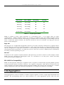
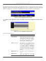
1
D-Link ™ DES-3250TG
Standalone Layer 2 Switch
User’s Guide
____________________
Information in this document is subject to change without notice.
© 2003 D-Link Computer Corporation. All rights reserved.
Reproduction in any manner whatsoever without the written permission of D-Link Computer Corporation is strictly forbidden.
Trademarks used in this text: D-Link and the D-Link logo are trademarks of D-Link Computer Corporation; Microsoft and Windows are registered trademarks
of Microsoft Corporation.
Other trademarks and trade names may be used in this document to refer to either the entities claiming the marks and names or their products. D-Link
Computer Corporation disclaims any proprietary interest in trademarks and trade names other than its own.
FCC Warning
This equipment has been tested and found to comply with the limits for a Class A digital device, pursuant to Part 15 of the FCC Rules. These limits are
designed to provide reasonable protection against harmful interference when the equipment is operated in a commercial environment. This equipment
generates, uses, and can radiate radio frequency energy and, if not installed and used in accordance with this user’s guide, may cause harmful interference to
radio communications. Operation of this equipment in a residential area is likely to cause harmful interference in which case the user will be required to correct
the interference at his own expense.
CE Mark Warning
This is a Class A product. In a domestic environment, this product may cause radio interference in which case the user may be required to take adequate
measures.
Warnung!
Dies ist ein Produkt der Klasse A. Im Wohnbereich kann dieses Produkt Funkstoerungen verursachen. In diesem Fall kann vom
Benutzer verlangt werden, angemessene Massnahmen zu ergreifen.
Precaución!
Este es un producto de Clase A. En un entorno doméstico, puede causar interferencias de radio, en cuyo case, puede requerirse
al usuario para que adopte las medidas adecuadas.
Attention!
Ceci est un produit de classe A. Dans un environnement domestique, ce produit pourrait causer des interférences radio, auquel
cas l`utilisateur devrait prendre les mesures adéquates.
Attenzione!
Il presente prodotto appartiene alla classe A. Se utilizzato in ambiente domestico il prodotto può causare interferenze radio, nel
cui caso è possibile che l`utente debba assumere provvedimenti adeguati.
VCCI Warning
BSMI Warning
October 2003 P/N 651TG3250045
Table of Contents
Introduction .......................................................................................................................................... 1
Features ............................................................................................................................................. 1
Ports ................................................................................................................................................ 1
Performance Features......................................................................................................................... 1
Traffic Classification and Prioritization ............................................................................................. 2
Management .................................................................................................................................... 2
Fast Ethernet Technology ................................................................................................................... 3
Gigabit Ethernet Technology............................................................................................................... 3
Unpacking and Setup............................................................................................................................ 4
Unpacking .......................................................................................................................................... 4
Installation ......................................................................................................................................... 4
Desktop or Shelf Installation ............................................................................................................ 4
Rack Installation .............................................................................................................................. 5
Power on............................................................................................................................................. 6
Power Failure ................................................................................................................................... 6
Identifying External Components .......................................................................................................... 7
Front Panel......................................................................................................................................... 7
Rear Panel .......................................................................................................................................... 7
Side Panels ......................................................................................................................................... 8
Gigabit Combo Ports........................................................................................................................... 8
LED Indicators ................................................................................................................................... 9
Connecting The Switch........................................................................................................................ 10
Switch to End Node .......................................................................................................................... 10
Switch to Hub or Switch ................................................................................................................... 10
10BASE-T Device ........................................................................................................................... 11
100BASE-TX Device ....................................................................................................................... 11
Switch Management and Operating Concepts ..................................................................................... 12
Local Console Management .............................................................................................................. 12
Diagnostic (console) port (RS-232 DCE).......................................................................................... 12
Switch IP Address............................................................................................................................. 13
SNMP ............................................................................................................................................... 14
MIBs................................................................................................................................................. 15
Packet Forwarding ............................................................................................................................ 16
802.1w Rapid Spanning Tree ............................................................................................................ 16
Link Aggregation............................................................................................................................... 17
VLANs .............................................................................................................................................. 18
IP Addresses ..................................................................................................................................... 23
Internet Protocols ............................................................................................................................. 26
Packet Headers................................................................................................................................. 30
Web-Based Switch Management.......................................................................................................... 35
Introduction ..................................................................................................................................... 35
Before You Start ............................................................................................................................... 35
Getting Started ................................................................................................................................. 35
Configuring the Switch ..................................................................................................................... 36
User Accounts Management ........................................................................................................... 36
Save Changes................................................................................................................................. 37
Using Web-Based Management......................................................................................................... 38
iii
Configuration ................................................................................................................................... 40
IP Address...................................................................................................................................... 41
Switch Information......................................................................................................................... 43
Advanced Settings.......................................................................................................................... 44
Port Configuration.......................................................................................................................... 45
Port Mirroring ................................................................................................................................ 47
Link Aggregation ............................................................................................................................ 48
IGMP.............................................................................................................................................. 50
Spanning Tree................................................................................................................................ 53
Forwarding Filtering....................................................................................................................... 58
VLANs ............................................................................................................................................ 60
Port Bandwidth .............................................................................................................................. 65
SNTP Settings ................................................................................................................................ 66
Port Security .................................................................................................................................. 68
QOS (Quality of Service) ................................................................................................................. 70
LACP.............................................................................................................................................. 77
Access Profile Table........................................................................................................................ 79
System Log Servers ........................................................................................................................ 83
PAE Access Entity .......................................................................................................................... 84
Management..................................................................................................................................... 91
Security IP ..................................................................................................................................... 91
User Accounts................................................................................................................................ 91
SNMPV3......................................................................................................................................... 92
Monitoring ...................................................................................................................................... 100
Port Utilization ............................................................................................................................. 100
Packets ........................................................................................................................................ 101
Errors .......................................................................................................................................... 106
Size .............................................................................................................................................. 109
MAC Address ............................................................................................................................... 111
IGMP Snooping Group ................................................................................................................. 113
IGMP Snooping Forwarding.......................................................................................................... 113
VLAN Status ................................................................................................................................ 114
Router Port .................................................................................................................................. 114
Port Access Control ...................................................................................................................... 115
Maintenance................................................................................................................................... 115
TFTP Utilities ............................................................................................................................... 115
Switch History.............................................................................................................................. 117
Ping Test ...................................................................................................................................... 117
Save Changes............................................................................................................................... 118
Reboot Services............................................................................................................................ 118
Logout.......................................................................................................................................... 120
Warranty........................................................................................................................................... 121
All countries and regions except USA ........................................................................................... 121
USA Only ..................................................................................................................................... 122
Technical Specifications .................................................................................................................... 124
Understanding and Troubleshooting the Spanning Tree Protocol....................................................... 126
Index................................................................................................................................................. 135
iv
D-Link DES-3250TG Standalone Layer 2 Switch
Intended Readers
The DES-3250 User’s Guide contains information for setup and management and of the DES-3250TG switch.
This guide is intended for network managers familiar with network management concepts and terminology.
Notes, Notices, and Cautions
NOTE: A NOTE indicates important information that helps you make better use of your
device.
NOTICE: A NOTICE indicates either potential damage to hardware or loss of data and tells
you how to avoid the problem.
CAUTION: A CAUTION indicates a potential for property damage, personal injury, or death.
v
D-Link DES-3250TG Standalone Layer 2 Switch
Safety Instructions
Use the following safety guidelines to ensure your own personal safety and to help protect your system from potential damage.
Throughout this safety section, the caution icon ( ) is used to indicate cautions and precautions that you need to review and
follow.
Safety Cautions
To reduce the risk of bodily injury, electrical shock, fire, and damage to the equipment, observe the following precautions.
Observe and follow service markings. Do not service any product except as explained in your system documentation. Opening
or removing covers that are marked with the triangular symbol with a lightning bolt may expose you to electrical shock. Only
a trained service technician should service components inside these compartments.
If any of the following conditions occur, unplug the product from the electrical outlet and replace the part or contact your
trained service provider:
– The power cable, extension cable, or plug is damaged.
– An object has fallen into the product.
– The product has been exposed to water.
– The product has been dropped or damaged.
– The product does not operate correctly when you follow the operating instructions.
• Keep your system away from radiators and heat sources. Also, do not block cooling vents.
• Do not spill food or liquids on your system components, and never operate the product in a wet environment. If the
system gets wet, see the appropriate section in your troubleshooting guide or contact your trained service provider.
• Do not push any objects into the openings of your system. Doing so can cause fire or electric shock by shorting out
interior components.
• Use the product only with approved equipment.
• Allow the product to cool before removing covers or touching internal components.
• Operate the product only from the type of external power source indicated on the electrical ratings label. If you are
not sure of the type of power source required, consult your service provider or local power company.
• To help avoid damaging your system, be sure the voltage selection switch (if provided) on the power supply is set to
match the power available at your location:
– 115 volts (V)/60 hertz (Hz) in most of North and South America and some Far Eastern countries such as South
Korea and Taiwan
– 100 V/50 Hz in eastern Japan and 100 V/60 Hz in western Japan
– 230 V/50 Hz in most of Europe, the Middle East, and the Far East
• Also be sure that attached devices are electrically rated to operate with the power available in your location.
• Use only approved power cable(s). If you have not been provided with a power cable for your system or for any ACpowered option intended for your system, purchase a power cable that is approved for use in your country. The power
cable must be rated for the product and for the voltage and current marked on the product's electrical ratings label.
The voltage and current rating of the cable should be greater than the ratings marked on the product.
vi
D-Link DES-3250TG Standalone Layer 2 Switch
Safety Instructions (continued)
•
•
•
•
•
•
•
To help prevent electric shock, plug the system and peripheral power cables into properly grounded electrical outlets.
These cables are equipped with three-prong plugs to help ensure proper grounding. Do not use adapter plugs or
remove the grounding prong from a cable. If you must use an extension cable, use a 3-wire cable with properly
grounded plugs.
Observe extension cable and power strip ratings. Make sure that the total ampere rating of all products plugged into
the extension cable or power strip does not exceed 80 percent of the ampere ratings limit for the extension cable or
power strip.
To help protect your system from sudden, transient increases and decreases in electrical power, use a surge
suppressor, line conditioner, or uninterruptible power supply (UPS).
Position system cables and power cables carefully; route cables so that they cannot be stepped on or tripped over. Be
sure that nothing rests on any cables.
Do not modify power cables or plugs. Consult a licensed electrician or your power company for site modifications.
Always follow your local/national wiring rules.
When connecting or disconnecting power to hot-pluggable power supplies, if offered with your system, observe the
following guidelines:
– Install the power supply before connecting the power cable to the power supply.
– Unplug the power cable before removing the power supply.
– If the system has multiple sources of power, disconnect power from the system by
unplugging all power cables from the power supplies.
Move products with care; ensure that all casters and/or stabilizers are firmly connected to the system. Avoid sudden
stops and uneven surfaces.
General Precautions for Rack-Mountable Products
Observe the following precautions for rack stability and safety. Also refer to the rack installation documentation
accompanying the system and the rack for specific caution statements and procedures.
Systems are considered to be components in a rack. Thus, "component" refers to any system as well as to various peripherals
or supporting hardware.
CAUTION: Installing systems in a rack without the front and side stabilizers
installed could cause the rack to tip over, potentially resulting in bodily injury under
certain circumstances. Therefore, always install the stabilizers before installing
components in the rack.
After installing system/components in a rack, never pull more than one component
out of the rack on its slide assemblies at one time. The weight of more than one
extended component could cause the rack to tip over and may result in serious
injury.
•
Before working on the rack, make sure that the stabilizers are secured to the rack, extended to the floor, and that the
full weight of the rack rests on the floor. Install front and side stabilizers on a single rack or front stabilizers for joined
multiple racks before working on the rack.
vii
D-Link DES-3250TG Standalone Layer 2 Switch
Safety Instructions (continued)
Always load the rack from the bottom up, and load the heaviest item in the rack first.
Make sure that the rack is level and stable before extending a component from the rack.
Use caution when pressing the component rail release latches and sliding a component into or out of a rack; the slide rails can
pinch your fingers.
After a component is inserted into the rack, carefully extend the rail into a locking position, and then slide the component into
the rack.
Do not overload the AC supply branch circuit that provides power to the rack. The total rack load should not exceed 80
percent of the branch circuit rating.
Ensure that proper airflow is provided to components in the rack.
Do not step on or stand on any component when servicing other components in a rack.
NOTE: A qualified electrician must perform all connections to DC power and to
safety grounds. All electrical wiring must comply with applicable local or national
codes and practices.
CAUTION: Never defeat the ground conductor or operate the equipment in the
absence of a suitably installed ground conductor. Contact the appropriate electrical
inspection authority or an electrician if you are uncertain that suitable grounding is
available.
CAUTION: The system chassis must be positively grounded to the rack cabinet
frame. Do not attempt to connect power to the system until grounding cables are
connected. Completed power and safety ground wiring must be inspected by a
qualified electrical inspector. An energy hazard will exist if the safety ground cable
is omitted or disconnected.
Protecting Against Electrostatic Discharge
Static electricity can harm delicate components inside your system. To prevent static damage, discharge static electricity from
your body before you touch any of the electronic components, such as the microprocessor. You can do so by periodically
touching an unpainted metal surface on the chassis.
You can also take the following steps to prevent damage from electrostatic discharge (ESD):
1.
2.
3.
When unpacking a static-sensitive component from its shipping carton, do not remove the component from
the antistatic packing material until you are ready to install the component in your system. Just before
unwrapping the antistatic packaging, be sure to discharge static electricity from your body.
When transporting a sensitive component, first place it in an antistatic container or packaging.
Handle all sensitive components in a static-safe area. If possible, use antistatic floor pads and workbench
pads and an antistatic grounding strap.
viii
D-Link DES-3250TG Standalone Layer 2 Switch
1
I NTRODUCTION
This section describes the functionality features of the DES-3250TG.
Features
The DES-3250TG Switch was designed for easy installation and high performance in an environment
where traffic on the network and the number of users increase continuously.
Switch features include:
Ports
•
Forty-eight high-performance NWay ports all operating at 10/100 Mbps for connecting to end
stations, servers and hubs.
•
All 48 10/100 UTP ports can auto-negotiate (NWay) between 10Mbps/100Mbps, half-duplex or
full duplex.
•
One front panel slide-in module interface for a 2-port 1000BASE-T module (provided) and one
front panel slide-in module interface for a 2-port Mini GBIC Gigabit Ethernet module (optional).
Please note that although these two front panel modules can be used simultaneously, the ports
must be different. For example, if port 49x is used on the Mini GBIC module, port 49x is not
available on the 1000BASE-T module, and vice versa.
•
RS-232 DCE Diagnostic port (console port) for setting up and managing the Switch via a
connection to a console terminal or PC using a terminal emulation program.
Performance Features
•
Store and forward switching scheme.
•
Full and half-duplex for both 10Mbps and 100Mbps connections. The front-port Gigabit Ethernet
module operates at full duplex only. Full duplex allows the switch port to simultaneously
transmit and receive data, and only works with connections to full-duplex capable end stations
and switches. Connections to hubs must take place at half-duplex.
•
Auto-polarity detection and correction of incorrect polarity on the transmit and receive twistedpair at each port.
•
IEEE 802.3z compliant for Mini GBIC ports (optional module).
1
D-Link DES-3250TG Standalone Layer 2 Switch
•
IEEE 802.3ab compliant for 1000BASE-T (Copper) Gigabit ports (optional module).
•
Data forwarding rate 14,880 pps per port at 100% of wire-speed for 10Mbps speed.
•
Data forwarding rate 148,800 pps per port at 100% of wire-speed for 100Mbps speed.
•
Data filtering rate eliminates all error packets, runts, etc. at 14,880 pps per port at 100% of wirespeed for 10Mbps speed.
•
Data filtering rate eliminates all error packets, runts, etc. at 148,800 pps per port at 100% of
wire-speed for 100Mbps speed.
•
8K active MAC address entry table per device with automatic learning and aging (10 to 1,000,000
seconds).
•
64 MB packet buffer per device.
•
Supports Port Mirroring.
•
Supports Port Trunking.
•
802.1D Spanning Tree support.
•
802.1Q Tagged VLAN support – up to 255 VLANs per device (one VLAN is reserved for internal
use).
•
GVRP – (GARP VLAN Registration Protocol) support for dynamic VLAN registration.
•
802.1p Priority support with 4 priority queues.
•
IGMP Snooping support.
Traffic Classification and Prioritization
•
Based on 802.1p priority bits.
•
Four priority queues.
Management
•
RS-232 console port for out-of-band network management via a console terminal or PC.
•
Fast Spanning Tree Algorithm Protocol for creation of alternative backup paths and prevention of
network loops.
•
SNMP V1, V2C, and V3 are supported.
•
Fully configurable in-band control for SNMP based software.
•
Flash memory for software upgrades. This can be done in-band via TFTP or out-of-band via the
console.
•
Built-in SNMP management:
SNMP V2-MIB (RFC 1907).
Bridge MIB (RFC 1493).
2
D-Link DES-3250TG Standalone Layer 2 Switch
MIB-II (RFC 1213).
IF MIB (RFC 2233).
Entity MIB (RFC 2737).
RMON MIB (RFC 1757) – 4 groups. The RMON specification defines the Counters for the
Receive function only. However, the DES-3250TG implements counters for both receive
and transmit functions.
802.1p MIB (RFC 2674).
Ether-Like MIB (RFC 2358) – dot3StatsTable.
•
Supports Web-based management.
•
CLI management support.
•
TFTP support.
•
BOOTP support.
•
DHCP Client support.
•
Password enabled.
Fast Ethernet Technology
100Mbps Fast Ethernet (or 100BASE-T) is a standard specified by the IEEE 802.3 LAN committee. It is
an extension of the 10Mbps Ethernet standard with the ability to transmit and receive data at 100Mbps,
while maintaining the Carrier Sense Multiple Access with Collision Detection (CSMA/CD) Ethernet
protocol.
Gigabit Ethernet Technology
Gigabit Ethernet is an extension of IEEE 802.3 Ethernet utilizing the same packet structure, format,
and support for full duplex and management objects, but with a tenfold increase in theoretical
throughput over 100Mbps Fast Ethernet and a one hundred-fold increase over 10Mbps Ethernet. Since
it is compatible with all 10Mbps and 100Mbps Ethernet environments, Gigabit Ethernet provides a
straightforward upgrade without wasting a company’s existing investment in hardware, software, and
trained personnel.
3
D-Link DES-3250TG Standalone Layer 2 Switch
2
U NPACKING AND S ETUP
This chapter provides unpacking and setup information for the Switch.
Unpacking
Open the shipping carton of the Switch and carefully unpack its contents. The carton should contain
the following items:
•
One DES-3250TG Standalone Layer 2 Switch
•
Mounting kit: 2 mounting brackets and screws
•
Four rubber feet with adhesive backing
•
One AC power cord
•
This User’s Guide with Registration Card
If any item is found missing or damaged, please contact your local D-Link reseller for replacement.
Installation
Use the following guidelines when choosing a place to install the Switch:
• The surface must support at least 5 kg
• The power outlet should be within 1.82 meters (6 feet) of the device
• Visually inspect the power cord and see that it is secured to the AC power connector
• Make sure that there is proper heat dissipation from and adequate ventilation around the
switch. Do not place heavy objects on the switch
Desktop or Shelf Installation
When installing the Switch on a desktop or shelf, the rubber feet included with the device should first
be attached. Attach these cushioning feet on the bottom at each corner of the device. Allow adequate
space for ventilation between the device and the objects around it.
4
D-Link DES-3250TG Standalone Layer 2 Switch
Figure 2-1. Installing rubber feet for desktop installation
Rack Installation
The DES-3250TG can be mounted in an EIA standard-sized, 19-inch rack, which can be placed in a
wiring closet with other equipment. To install, attach the mounting brackets on the switch’s side panels
(one on each side) and secure them with the screws provided.
Figure 2- 2. Attaching the mounting brackets to the switch
Then, use the screws provided with the equipment rack to mount the switch on the rack.
Figure 2-3. Installing the switch on an equipment rack
5
D-Link DES-3250TG Standalone Layer 2 Switch
Power on
The DES-3250TG switch can be used with AC power supply 100 - 240 VAC, 50 - 60 Hz. The power
switch is located at the rear of the unit adjacent to the AC power connector and the system fan. The
switch’s power supply will adjust to the local power source automatically and may be turned on without
having any or all LAN segment cables connected.
After the power switch is turned on, the LED indicators should respond as follows:
• All LED indicators will momentarily blink. This blinking of the LED indicators represents a
reset of the system
• The power LED indicator is always on after the power is turned ON
• The console LED indicator will blink while the Switch loads onboard software and performs a
self-test. It will remain ON if there is a connection at the RS-232 port, otherwise this LED
indicator is OFF
Power Failure
As a precaution in the event of a power failure, unplug the switch. When the power supply is restored,
plug the switch back in.
6
D-Link DES-3250TG Standalone Layer 2 Switch
3
I DENTIFYING E XTERNAL C OMPONENTS
This chapter describes the front panel, rear panel, side panels, and optional plug-in module, and LED
indicators of the DES-3250TG.
Front Panel
The front panel of the Switch consists of LED indicators, an RS-232 communication port, 48 (10/100
Mbps) Ethernet/Fast Ethernet ports, and a pair of Gigabit Ethernet Combo ports for 1000BASE-T (plugin module provided) and Mini GBIC connections (optional plug-in module).
Figure 3-1. Front panel view of the Switch
● Comprehensive LED indicators display the status of the switch and the network (see the LED
Indicators section below).
● An RS-232 DCE console port for setting up and managing the switch via a connection to a
console terminal or PC using a terminal emulation program.
● Forty-eight high-performance NWay Ethernet ports, all of which operate at 10/100 Mbps for
connections to end stations, servers and hubs. All ports can auto-negotiate between 10Mbps
or 100Mbps and full or half duplex.
● Two Gigabit Ethernet Combo ports for making 1000BASE-T and Mini GBIC connections.
Rear Panel
The rear panel of the switch consists of two fans and an AC power connector.
Figure 3-2. Rear panel view of the Switch
7
D-Link DES-3250TG Standalone Layer 2 Switch
The system fans are used to dissipate heat. The sides of the system also provide heat vents to serve the
same purpose. Do not block these openings, and leave at least 6 inches of space at the rear and sides of
the switch for proper ventilation. Be reminded that without proper heat dissipation and air circulation,
system components might overheat, which could lead to system failure. The AC power connector is a
standard three-pronged connector that supports the power cord. Plug-in the female connector of the
provided power cord into this socket, and the male side of the cord into a power outlet. Supported input
voltages range from 100 ~ 240 VAC at 50 ~ 60 Hz.
Side Panels
Each side panel contains heat vents to help to dissipate heat.
Figure 3-3. Side panel views of the Switch
The system fans are used to dissipate heat. The sides of the system also provide heat vents to serve the
same purpose. Do not block these openings, and leave at least 6 inches of space at the rear and sides of
the switch for proper ventilation. Be reminded that without proper heat dissipation and air circulation,
system components might overheat, which could lead to system failure.
Gigabit Combo Ports
In addition to the 48 10/100 Mbps ports, the Switch features two Gigabit Ethernet Combo ports. These
two ports are 1000BASE-T copper ports (provided) and Mini-GBIC ports (optional). See the diagram
below to view the two Mini-GBIC port modules being plugged into the Switch. Please note that although
these two front panel modules can be used simultaneously, the ports must be different. The GBIC port
will always have the highest priority.
Figure 3-4. Mini-GBIC modules plug-in to the Switch
8
D-Link DES-3250TG Standalone Layer 2 Switch
LED Indicators
The LED indicators of the Switch include Power, Console, and Link/Act. The following shows the LED
indicators for the Switch along with an explanation of each indicator.
Figure 3-5. The LED Indicators
● Power – This indicator on the front panel should be lit during the Power-On Self Test (POST).
It will light green approximately 2 seconds after the switch is powered on to indicate the ready
state of the device.
● Console – This indicator is lit green when the switch is being managed via local console
management through the RS-232 console port.
● Link/Act – These indicators are located to the left and right of each port. They are lit when
there is a secure connection (or link) to a device at any of the ports. The LEDs blink whenever
there is reception or transmission (i.e. Activity--Act) of data occurring at a port.
9
D-Link DES-3250TG Standalone Layer 2 Switch
4
C ONNECTING T HE S WITCH
This chapter describes how to connect the DES-3250TG to your Ethernet/Fast Ethernet/Gigabit
Ethernet network. The Switch’s auto-detection feature allows all 48 10/100 ports to support both MDIII and MDI-X connections.
Switch to End Node
End nodes include PCs outfitted with a 10, 100, or 10/100 Mbps RJ-45 Ethernet/Fast Ethernet
Network Interface Card (NIC) and most routers.
An end node can be connected to the Switch via a two-pair Category 3, 4, or 5 UTP/STP cable. The end
node should be connected to any of the ports (1x - 48x) on the switch.
Figure 4-1. Switch connected to an End Node
•
The Link/Act LEDs in the top row for each UTP port light green when the link is valid. A
blinking LED in the top row indicates packet activity on that port.
Switch to Hub or Switch
These connections can be accomplished in a number of ways using a normal cable.
● A 10BASE-T hub or switch can be connected to the Switch via a two-pair Category 3, 4 or 5
UTP/STP cable.
● A 100BASE-TX hub or switch can be connected to the Switch via a two-pair Category 5
UTP/STP cable.
10
D-Link DES-3250TG Standalone Layer 2 Switch
Figure 4-2. Switch connected to a port on a hub or switch using a straight or crossover cable
10BASE-T Device
For a 10BASE-T device, the Switch’s LED indicators should display the following:
● Link/Act indicator is ON.
100BASE-TX Device
For a 100BASE-TX device, the Switch’s LED indicators should display the following:
● Link/Act is ON.
11
D-Link DES-3250TG Standalone Layer 2 Switch
5
S WITCH M ANAGEMENT AND O PERATING
C ONCEPTS
This chapter discusses many of the concepts and features used to manage the switch, as well as the
concepts necessary for the user to understand the functioning of the switch. Further, this chapter
explains many important points regarding these features.
Configuring the switch to implement these concepts and make use of its many features is discussed in
detail in the next chapters.
Local Console Management
A local console is a terminal or a workstation running a terminal emulation program that is connected
directly to the switch via the RS-232 serial console port on the front of the switch. A console connection
is referred to as an ‘Out-of-Band’ connection, meaning that console is connected to the switch using a
different circuit than that used for normal network communications. So, the console can be used to set
up and manage the switch even if the network is down.
Local console management uses the terminal connection to operate the console program built-in to the
switch. A network administrator can manage, control, and monitor the switch from the console
program.
The DES-3250TG contains a CPU, memory for data storage, flash memory for configuration data,
operational programs, and SNMP agent firmware. These components allow the switch to be actively
managed and monitored from either the console port or the network itself (out-of-band, or in-band).
Diagnostic (console) port (RS-232 DCE)
Out-of-band management requires connecting a terminal, such as a VT-100 or a PC running a terminal
emulation program (such as HyperTerminal, which is automatically installed with Microsoft Windows) a
to the RS-232 DCE console port of the Switch. Switch management using the RS-232 DCE console port
is called Local Console Management to differentiate it from management performed via management
platforms, such as D-View or HP OpenView. Web-based Management describes management of the
switch performed over the network (in-band) using the switch’s built-in Web-based management
program. The operations to be performed and the facilities provided by these two built-in programs are
identical.
The console port is set at the factory for the following configuration:
•
Baud rate:
9,600
•
Data width:
8 bits
•
Parity:
none
•
Stop bits:
1
12
D-Link DES-3250TG Standalone Layer 2 Switch
•
Flow Control
None
Make sure the terminal or PC you are using to make this connection is configured to match these
settings.
If you are having problems making this connection on a PC, make sure the emulation is set to VT100. If you still don’t see anything, try hitting <Ctrl> + r to refresh the screen.
Switch IP Address
Each Switch must be assigned its own IP Address, which is used for communication with an SNMP
network manager or other TCP/IP application (for example BOOTP, TFTP). The switch’s default IP
address is 10.90.90.90. You can change the default Switch IP Address to meet the specification of your
networking address scheme.
The switch is also assigned a unique MAC address by the factory. This MAC address cannot be
changed, and can be found from the initial boot console screen – shown below.
Figure 5- 1. Console Boot Screen
The switch’s MAC address can also be found from the console program under the Switch Information
menu item.
Setting an IP Address
The IP address for the switch must be set before it can be managed with the web-based manager. The
switch IP address may be automatically set using BOOTP or DHCP protocols, in which case the actual
address assigned to the switch must be known.
The IP address may alternatively be set using the Command Line Interface (CLI) over the console
serial port as follows:
1. Starting at the command line prompt local>, enter the commands config ipif System
ipaddress xxx.xxx.xxx.xxx/yyy.yyy.yyy.yyy. Where the x’s represent the IP address to be
assigned to the IP interface named System and the y’s represent the corresponding subnet
mask.
2. Alternatively, you can enter the commands config ipif System ipaddress
xxx.xxx.xxx.xxx/z. Where the x’s represent the IP address to be assigned to the IP interface
13
D-Link DES-3250TG Standalone Layer 2 Switch
named System and the z represents the corresponding number of subnets in CIDR
notation.
Using this method, the switch can be assigned an IP address and subnet mask that can then be used to
connect a management station to the switch’s Web-based management agent.
SNMP
The Simple Network Management Protocol (SNMP) is an OSI layer 7 (the application layer) protocol for
remotely monitoring and configuring network devices. SNMP enables network management stations to
read and modify the settings of gateways, routers, switches, and other network devices. SNMP can be
used to perform many of the same functions as a directly connected console, or can be used within an
integrated network management software package such as DView or HP OpenView.
SNMP performs the following functions:
•
•
•
Sending and receiving SNMP packets through the IP protocol.
Collecting information about the status and current configuration of network devices.
Modifying the configuration of network devices.
The DES-3250TG has a software program called an ‘agent’ that processes SNMP requests, but the user
program that makes the requests and collects the responses runs on a management station (a
designated computer on the network). The SNMP agent and the user program both use the UDP/IP
protocol to exchange packets.
Authentication
The authentication protocol ensures that both the router SNMP agent and the remote user SNMP
application program discard packets from unauthorized users. Authentication is accomplished using
‘community strings’, which function like passwords. The remote user SNMP application and the router
SNMP must use the same community string.
Traps
Traps are messages that alert network personnel of events that occur on the Switch. The events can be
as serious as a reboot (someone accidentally turned OFF the Switch), or less serious like a port status
change. The Switch generates traps and sends them to the trap recipient (or network manager).
Trap recipients are special users of the network who are given certain rights and access in overseeing
the maintenance of the network. Trap recipients will receive traps sent from the Switch; they must
immediately take certain actions to avoid future failure or breakdown of the network.
You can also specify which network managers may receive traps from the Switch by entering a list of the
IP addresses of authorized network managers. Up to ten trap recipient IP addresses, and ten
corresponding SNMP community strings can be entered.
SNMP community strings function like passwords in that the community string entered for a given IP
address must be used in the management station software, or a trap will be sent.
The following are trap types the switch can send to a trap recipient:
• Cold Start – This trap signifies that the Switch has been powered up and initialized such that
software settings are reconfigured and hardware systems are rebooted. A cold start is different
14
D-Link DES-3250TG Standalone Layer 2 Switch
from a factory reset in that configuration settings saved to non-volatile RAM used to
reconfigure the switch.
• System Restart – This trap contains the reboot information.
• Authentication Failure – This trap signifies that someone has tried to logon to the switch
using an invalid SNMP community string. The switch automatically stores the source IP
address of the unauthorized user.
• Topology Change – A Topology Change trap is sent by the Switch when any of its configured
ports transitions from the Learning state to the Forwarding state, or from the Forwarding
state to the Blocking state. The trap is not sent if a new root trap is sent for the same
transition.
• New Root – This trap is sent by the switch whenever a new root port is elected within an STP
group.
• Link Change Event – This trap is sent whenever the link of a port changes from link up to
link down or from link down to link up.
• Save to NV-RAM – This trap is sent whenever “Save all configuration of device to NV-RAM”
has been processed.
• File Transfer Status Change – This trap is sent for file transfer status change notification.
• Set to Factory Default – The trap is sent whenever the “Set to factory default setting” has
been processed.
MIBs
Management and counter information are stored in the Switch in the Management Information Base
(MIB). The Switch uses the standard MIB-II Management Information Base module. Consequently,
values for MIB objects can be retrieved from any SNMP-based network management software. In
addition to the standard MIB-II, the Switch also supports its own proprietary enterprise MIB as an
extended Management Information Base. These MIBs may also be retrieved by specifying the MIB’s
Object-Identity (OID) at the network manager. MIB values can be either read-only or read-write.
Read-only MIBs variables can be either constants that are programmed into the Switch, or variables
that change while the Switch is in operation. Examples of read-only constants are the number of port
and type of ports. Examples of read-only variables are the statistics counters such as the number of
errors that have occurred, or how many kilobytes of data have been received and forwarded through a
port.
Read-write MIBs are variables usually related to user-customized configurations. Examples of these are
the Switch’s IP Address, Spanning Tree Algorithm parameters, and port status.
If you use a third-party vendors’ SNMP software to manage the Switch, a diskette listing the Switch’s
propriety enterprise MIBs can be obtained by request. If your software provides functions to browse or
modify MIBs, you can also get the MIB values and change them (if the MIBs’ attributes permit the write
operation). This process however can be quite involved, since you must know the MIB OIDs and retrieve
them one by one.
15
D-Link DES-3250TG Standalone Layer 2 Switch
Packet Forwarding
The Switch enters the relationship between destination MAC addresses and the Ethernet port the
destination resides on into its forwarding table. This information is then used to forward packets. This
reduces broadcast storms on the network, because packets, instead of being transmitted to all ports,
are transmitted to the destination port only. Example: if Port 1 receives a packet destined for a station
on Port 2, the Switch transmits that packet through Port 2 only, and transmits nothing through the
other ports. This process is referred to as ‘learning’ the network topology.
MAC Address Aging Time
The Aging Time affects the learning process of the Switch. Dynamic forwarding table entries, which are
made up of the source MAC addresses and their associated port numbers, are deleted from the table if
they are not accessed within the aging time.
The aging time can be from 10 to 1,000,000 seconds with a default value of 300 seconds. A very long
aging time can result in dynamic forwarding table entries that are out-of-date or no longer exist. This
may cause incorrect packet forwarding decisions by the switch.
If the Aging Time is too short however, many entries may be aged out too soon. This will result in a high
percentage of received packets whose destination addresses cannot be found in the forwarding table, in
which case the switch will broadcast the packet to all ports, negating many of the benefits of having a
switch.
Static forwarding entries are not affected by the aging time.
802.1w Rapid Spanning Tree
The Switch implements two versions of the Spanning Tree Protocol, the Rapid Spanning Tree Protocol
(RSTP) as defined by the IEEE 802.1w specification and a version compatible with the IEEE 802.1d STP.
RSTP can operate with legacy equipment implementing IEEE 802.1d, however the advantages of using
RSTP will be lost.
The IEEE 802.1w Rapid Spanning Tree Protocol (RSTP) evolved from the 802.1d STP standard. RSTP
was developed in order to overcome some limitations of STP that impede the function of some recent
switching innovations, in particular, certain Layer 3 function that are increasingly handled by Ethernet
switches. The basic function and much of the terminology is the same as STP. Most of the settings
configured for STP are also used for RSTP. This section introduces some new Spanning Tree concepts
and illustrates the main differences between the two protocols.
Port Transition States
An essential difference between the two protocols is in the way ports transition to a forwarding state and
the in the way this transition relates to the role of the port (forwarding or not forwarding) in the
topology. RSTP combines the transition states disabled, blocking, and listening used in 802.1d and
creates a single state: discarding. In either case, ports do not forward packets; in the STP port transition
states disabled, blocking, or listening, or in the RSTP port state discarding, there is no functional
difference, the port is not active in the network topology. Table 5-1 below compares how the two
protocols differ regarding the port state transition.
16
D-Link DES-3250TG Standalone Layer 2 Switch
802.1d STP
802.1w RSTP
Forwarding
Learning
Disabled
Discarding
No
No
Blocking
Discarding
No
No
Listening
Discarding
No
No
Learning
Learning
No
Yes
Forwarding
Forwarding
Yes
Yes
Table 5- 1. Comparing Port States
RSTP is capable of more rapid transition to a forwarding state – it no longer relies on timer
configurations – RSTP-compliant bridges are sensitive to feedback from other RSTP-compliant bridge
links. Ports do not need to wait for the topology to stabilize before transitioning to a forwarding state. In
order to allow this rapid transition, the protocol introduces two new variables: the edge port and the
point-to-point (P2P) port.
Edge Port
The edge port is a configurable designation used for a port that is directly connected to a segment where
a loop cannot be created. An example would be a port connected directly to a single workstation. Ports
that are designated as edge ports, transition to a forwarding state immediately without going through
the listening and learning states. An edge port loses its status if it receives a BPDU packet, immediately
becoming a normal spanning tree port.
P2P Port
A P2P port is also capable of rapid transition. P2P ports may be used to connect to other bridges. Under
RSTP, all ports operating in full-duplex mode are considered to be P2P ports, unless manually
overridden through configuration.
802.1d/802.1w Compatibility
RSTP can interoperate with legacy equipment and is capable of automatically adjusting BPDU packets
to 802.1d format when necessary. However, any segment using 802.1 STP will not benefit from the
rapid transition and rapid topology change detection of RSTP. The protocol also provides for a variable
used for migration in the event that legacy equipment on a segment is updated to use RSTP.
Link Aggregation
Link aggregation is used to combine a number of ports together to make a single high-bandwidth data
pipeline. The participating parts are called members of a link aggregation group, with one port
17
D-Link DES-3250TG Standalone Layer 2 Switch
designated as the master port of the group. Since all members of the link aggregation group must be
configured to operate in the same manner, the configuration of the master port is applied to all
members of the link aggregation group. Thus, when configuring the ports in a link aggregation group,
you only need to configure the master port.
The DES-3250TG supports link aggregation groups, which may include from two to eight switch ports
each, except for a Gigabit link aggregation group which consists of the two (optional) Gigabit Ethernet
ports of the front panel.
Figure 5- 2. Link Aggregation Group
Data transmitted to a specific host (destination address) will always be transmitted over the same port
in a link aggregation group. This allows packets in a data stream to arrive in the same order they were
sent. An aggregated link connection can be made with any other switch that maintains host-to-host
data streams over a single link aggregate port. Switches that use a load-balancing scheme that sends
the packets of a host-to-host data stream over multiple link aggregation ports cannot have an
aggregated connection with the DES-3250TG switch.
VLANs
A VLAN is a collection of end nodes grouped by logic rather than physical location. End nodes that
frequently communicate with each other are assigned to the same VLAN, regardless of where they are
located physically on the network. Logically, a VLAN can be equated to a broadcast domain, because
broadcast packets are forwarded only to members of the VLAN on which the broadcast was initiated.
18
D-Link DES-3250TG Standalone Layer 2 Switch
Notes About VLANs on the DES-3250TG
1. The DES-3250TG supports IEEE 802.1Q VLANs. The port untagging function can be used to
remove the 802.1Q tag from packet headers to maintain compatibility with devices that are tagunaware (that is, network devices that do not support IEEE 802.1Q VLANs or tagging).
2. The switch’s default is to assign all ports to a single 802.1Q VLAN named “default.”
IEEE 802.1Q VLANs
Some relevant terms:
•
Tagging – The act of putting 802.1Q VLAN information into the header of a packet.
•
Untagging – The act of stripping 802.1Q VLAN information out of the packet header.
•
Ingress port – A port on a switch where packets are flowing into the switch and VLAN decisions
must be made.
•
Egress port – A port on a switch where packets are flowing out of the switch, either to another
switch or to an end station, and tagging decisions must be made.
IEEE 802.1Q (tagged) VLANs are implemented on the DES-3250TG Layer 2 switch. 802.1Q VLANs
require tagging, which enables the VLANs to span an entire network (assuming all switches on the
network are IEEE 802.1Q-compliant).
Any port can be configured as either tagging or untagging. The untagging feature of IEEE 802.1Q VLANs
allow VLANs to work with legacy switches that don’t recognize VLAN tags in packet headers. The tagging
feature allows VLANs to span multiple 802.1Q-compliant switches through a single physical connection
and allows Spanning Tree to be enabled on all ports and work normally.
802.1Q VLAN Packet Forwarding
Packet forwarding decisions are made based upon the following three types of rules:
•
Ingress rules – rules relevant to the classification of received frames belonging to a VLAN.
•
Forwarding rules between ports – decides filter or forward the packet
•
Egress rules – determines if the packet must be sent tagged or untagged.
19
D-Link DES-3250TG Standalone Layer 2 Switch
Figure 5- 3. IEEE 802.1Q Packet Forwarding
802.1Q VLAN Tags
The figure below shows the 802.1Q VLAN tag. There are four additional octets inserted after the source
MAC address. Their presence is indicated by a value of 0x8100 in the EtherType field. When a packet’s
EtherType field is equal to 0x8100, the packet carries the IEEE 802.1Q/802.1p tag. The tag is
contained in the following two octets and consists of 3 bits or user priority, 1 bit of Canonical Format
Identifier (CFI – used for encapsulating Token Ring packets so they can be carried across Ethernet
backbones) and 12 bits of VLAN ID (VID). The 3 bits of user priority are used by 802.1p. The VID is the
VLAN identifier and is used by the 802.1Q standard. Because the VID is 12 bits long, 4094 unique
VLANs can be identified.
The tag is inserted into the packet header making the entire packet longer by four octets. All of the
information contained in the packet originally is retained.
Figure 5- 4. IEEE 802.1Q Tag
20
D-Link DES-3250TG Standalone Layer 2 Switch
The EtherType and VLAN ID are inserted after the MAC source address, but before the original
EtherType/Length or Logical Link Control. Because the packet is now a bit longer than it was originally,
the Cyclic Redundancy Check (CRC) must be recalculated.
Figure 5- 5. Adding an IEEE 802.1Q Tag
Port VLAN ID
Packets that are tagged (are carrying the 802.1Q VID information) can be transmitted from one 802.1Q
compliant network device to another with the VLAN information intact. This allows 802.1Q VLANs to
span network devices (and indeed, the entire network – if all network devices are 802.1Q compliant).
Unfortunately, not all network devices are 802.1Q compliant.
unaware. 802.1Q devices are referred to as tag-aware.
These devices are referred to as tag-
Prior to the adoption 802.1Q VLANs, port-based and MAC-based VLANs were in common use. These
VLANs relied upon a Port VLAN ID (PVID) to forward packets. A packet received on a given port would
be assigned that port’s PVID and then be forwarded to the port that corresponded to the packet’s
destination address (found in the switch’s forwarding table). If the PVID of the port that received the
packet is different from the PVID of the port that is to transmit the packet, the switch will drop the
packet.
Within the switch, different PVIDs mean different VLANs.
(remember that two VLANs cannot
communicate without an external router). So, VLAN identification based upon the PVIDs cannot create
VLANs that extend outside a given switch (or switch stack).
Every physical port on a switch has a PVID. 802.1Q ports are also assigned a PVID, for use within the
switch. If no VLANs are defined on the switch, all ports are then assigned to a default VLAN with a
PVID equal to 1. Untagged packets are assigned the PVID of the port on which they were received.
Forwarding decisions are based upon this PVID, insofar as VLANs are concerned. Tagged packets are
forwarded according to the VID contained within the tag. Tagged packets are also assigned a PVID, but
the PVID is not used to make packet forwarding decisions, the VID is.
Tag-aware switches must keep a table to relate PVIDs within the switch to VIDs on the network. The
switch will compare the VID of a packet to be transmitted to the VID of the port that is to transmit the
packet. If the two VIDs are different, the switch will drop the packet. Because of the existence of the
PVID for untagged packets and the VID for tagged packets, tag-aware and tag-unaware network devices
can coexist on the same network.
A switch port can have only one PVID, but can have as many VIDs as the switch has memory in its
VLAN table to store them.
Because some devices on a network may be tag-unaware, a decision must be made at each port on a
tag-aware device before packets are transmitted – should the packet to be transmitted have a tag or
21
D-Link DES-3250TG Standalone Layer 2 Switch
not? If the transmitting port is connected to a tag-unaware device, the packet should be untagged. If the
transmitting port is connected to a tag-aware device, the packet should be tagged.
Tagging and Untagging
Every port on an 802.1Q compliant switch can be configured as tagging or untagging.
Ports with tagging enabled will put the VID number, priority and other VLAN information into the
header of all packets that flow into and out of it. If a packet has previously been tagged, the port will not
alter the packet, thus keeping the VLAN information intact. The VLAN information in the tag can then
be used by other 802.1Q compliant devices on the network to make packet forwarding decisions.
Ports with untagging enabled will strip the 802.1Q tag from all packets that flow into and out of those
ports. If the packet doesn’t have an 802.1Q VLAN tag, the port will not alter the packet. Thus, all
packets received by and forwarded by an untagging port will have no 802.1Q VLAN information.
(Remember that the PVID is only used internally within the switch). Untagging is used to send packets
from an 802.1Q-compliant network device to a non-compliant network device.
Ingress Checking
A port on a switch where packets are flowing into the switch and VLAN decisions must be made is
referred to as an ingress port. If ingress filtering is enabled for a port, the switch will examine the VLAN
information in the packet header (if present) and decide whether or not to forward the packet.
If the packet is tagged with VLAN information, the ingress port will first determine if the ingress port
itself is a member of the tagged VLAN. If it is not, the packet will be dropped. If the ingress port is a
member of the 802.1Q VLAN, the switch then determines if the destination port is a member of the
802.1Q VLAN. If it is not, the packet is dropped. If the destination port is a member of the 802.1Q
VLAN, the packet is forwarded and the destination port transmits it to its attached network segment.
If the packet is not tagged with VLAN information, the ingress port will tag the packet with its own PVID
as a VID (if the port is a tagging port). The switch then determines if the destination port is a member of
the same VLAN (has the same VID) as the ingress port. If it does not, the packet is dropped. If it has the
same VID, the packet is forwarded and the destination port transmits it on its attached network
segment.
This process is referred to as ingress filtering and is used to conserve bandwidth within the switch by
dropping packets that are not on the same VLAN as the ingress port at the point of reception. This
eliminates the subsequent processing of packets that will just be dropped by the destination port.
The “Default” VLAN
The switch initially configures one VLAN, VID = 1, called the “default” VLAN. The factory default setting
assigns all ports on the switch to the “default” VLAN.
Packets cannot cross VLANs. If a member of one VLAN wants to connect to another VLAN, the link must
be through an external router.
If no VLANs are configured on the switch, then all packets will be forwarded to any destination port.
Packets with unknown destination addresses will be flooded to all ports. Broadcast and multicast
packets will also be flooded to all ports.
VLANs
VLANs use network-layer addresses (subnet address for TCP/IP) to determine VLAN membership. These
VLANs are based on layer 2 information, but this does not constitute a ‘routing’ function.
22
D-Link DES-3250TG Standalone Layer 2 Switch
IP Addresses
The Internet Protocol (IP) was designed for routing data between network sites. Later, it was adapted for
routing between networks (referred to as “subnets”) within a site. The IP defines a way of generating a
unique number that can be assigned each network in the Internet and each of the computers on each of
those networks. This number is called the IP address.
IP addresses use a “dotted decimal” notation. Here are some examples of IP addresses written in this
format:
1.
2.
3.
210.202.204.205
189.21.241.56
125.87.0.1
This allows IP address to be written in a string of four decimal (base 10) numbers. Computers can only
understand binary (base 2) numbers, and these binary numbers are usually grouped together in bytes,
or eight bits. (A bit is a binary digit – either a “1” or a “0”). The dots (periods) simply make the IP
address easier to read. A computer sees an IP address not as four decimal numbers, but as a long string
of binary digits (32 binary digits or 32 bits, IP addresses are 32-bit addresses).
The three IP addresses in the example above, written in binary form are:
1.
2.
3.
11010010.11001010.11001100.11001101
10111101.00010101.11110001.00111000
01111101.01010111.00000000.00000001
The dots are included to make the numbers easier to read.
Eight binary bits are called a ‘byte’ or an ‘octet’. An octet can represent any decimal value between ‘0’
(00000000) and ‘255’ (11111111). IP addresses, represented in decimal form, are four numbers whose
value is between ‘0’ to ‘255’. The total range of IP addresses are then:
Lowest possible IP address Highest possible IP address -
0.0.0.0
255.255.255.255
To convert decimal numbers to 8-bit binary numbers (and vice-versa), you can use the following chart:
7
Binary Octet Digit
2
Decimal Equivalent
Binary Number
128+64+32+16+8+4+2+1=
255
128
1
2
6
64
1
2
5
32
1
2
4
16
1
2
3
8
1
2
2
4
1
2
1
2
1
2
0
1
1
Table 5- 2. Binary to Decimal Conversion
Each digit in an 8-bit binary number (an octet) represents a power of two. The left-most digit represents
2 raised to the 7th power (2x2x2x2x2x2x2=128) while the right-most digit represents 2 raised to the 0th
power (any number raised to the 0th power is equal to one, by definition).
IP addresses actually consist of two parts, one identifying the network and one identifying the
destination (node) within the network.
The IP address discussed above is one part and a second number called the Subnet mask is the other
part. To make this a bit more confusing, the subnet mask has the same numerical form as an IP
address.
23
D-Link DES-3250TG Standalone Layer 2 Switch
Address Classes
Address classes refer to the range of numbers in the subnet mask. Grouping the subnet masks into
classes makes the task of dividing a network into subnets a bit easier.
There are five address classes. The first four bits in the IP address determine which class the IP address
falls in.
•
•
•
•
•
Class
Class
Class
Class
Class
A addresses begin with 0xxx, or 1 to 126 decimal.
B addresses begin with 10xx, or 128 to 191 decimal.
C addresses begin with 110x, or 192 to 223 decimal.
D addresses begin with 1110, or 224 to 239 decimal.
E addresses begin with 1111, or 240 to 254 decimal.
Addresses beginning with 01111111, or 127 decimal, are reserved. They are used for internal testing on
a local machine (called loopback). The address 127.0.0.1 can always be pinged from a local node
because it forms a loopback and points back to the same node.
Class D addresses are reserved for multicasting.
Class E Addresses are reserved for future use. They are not used for node addresses.
The part of the IP address that belongs to the network is the part that is ‘hidden’ by the ‘1’s in the
subnet mask. This can be seen below:
•
•
•
Class A
Class B
Class C
NETWORK.node.node.node
NETWORK.NETWORK.node.node
NETWORK.NETWORK.NETWORK.node
For example, the IP address 10.42.73.210 is a Class A address, so the Network part of the address
(called the Network Address) is the first octet (10.x.x.x). The node part of the address is the last three
octets (x.42.73.210).
To specify the network address for a given IP address, the node part is set to all “0”s. In our example,
10.0.0.0 specifies the network address for 10.42.73.210. When the node part is set to all “1”s, the
address specifies a broadcast address. So, 10.255.255.255 is the broadcast address for the network
10.0.0.0.
Subnet Masking
A subnet mask can be applied to an IP address to identify the network and the node parts of the
address. A bitwise logical AND operation between the IP address and the subnet mask results in the
Network Address.
For example:
00001010.00101010.01001001.11010010
11111111.00000000.00000000.00000000
10.42.73.210 Class A IP address
255.0.0.0
Class A Subnet Mask
00001010.00000000.00000000.00000000
10.0.0.0
Network Address
The Default subnet masks are:
•
•
•
Class A – 11111111.00000000.00000000.00000000
Class B – 11111111.11111111.00000000.00000000
Class C – 1111111.11111111.11111111.00000000
255.0.0.0
255.255.0.0
255.255.255.0
Additional bits can be added to the default subnet mask for a given Class to further subnet a network.
When a bitwise logical AND operation is performed between the subnet mask and the IP address, the
result defines the Subnet Address.
24
D-Link DES-3250TG Standalone Layer 2 Switch
Some restrictions apply to subnet addresses. Addresses of all “0”s and all “1”s are reserved for the local
network (when a host does not know it’s network address) and for all hosts on the network (the
broadcast address). This also applies to subnets. A subnet address cannot be all “0”s or all “1”s. A 1-bit
subnet mask is also not allowed.
Calculating the Number of Subnets and Nodes
To calculate the number of subnets and nodes, use the formula (2n – 2) where n = the number of bits in
either the subnet mask or the node portion of the IP address. Multiplying the number of subnets by the
number of nodes available per subnet gives the total number of nodes for the entire network.
Example
00001010.00101010.01001001.11010010
11111111.11100000.00000000.00000000
10.42.73.210
255.224.0.0
Class A IP address
Subnet Mask
00001010.00100000.00000000.00000000
00001010.00101010.11111111.11111111
10.32.0.0
10.32.255.255
Network Address
Broadcast Address
This example uses an 11-bit subnet mask. (There are three additional bits added to the default Class A
subnet mask). So the number of subnets is:
23 – 2 = 8 – 2 = 6
Subnets of all “0”s and all “1”s are not allowed, so two subnets are subtracted from the total.
The number of bits used in the node part of the address is 24 – 3 = 21 bits, so the total number of
nodes is:
221 – 2 = 2,097,152 – 2 = 2,097,150
Multiplying the number of subnets times the number of nodes gives 12,582,900 possible nodes.
Note that this is less than the 16,777,214 possible nodes that an unsubnetted class A network would
have.
Subnetting reduces the number of possible nodes for a given network, but increases the segmentation
of the network.
Classless InterDomain Routing – CIDR
Under CIDR, the subnet mask notation is reduced to simplified shorthand. Instead of specifying all of
the bits of the subnet mask, it is simply listed as the number of contiguous “1”s (bits) in the network
portion of the address. Look at the subnet mask of the above example in binary 11111111.11100000.00000000.00000000 – and you can see that there are 11 “1”s or 11 bits used to
mask the network address from the node address. Written in CIDR notation this becomes:
10.32.0.0/11
# of
Bits
Subnet Mask
# of
Subnets
# of
Hosts
Total Hosts
255.192.0.0
CID
R
Nota
tion
/10
2
2
8388604
3
255.224.0.0
/11
6
4
255.240.0.0
/12
14
5
6
7
8
255.248.0.0
255.252.0.0
255.254.0.0
255.255.0.0
/13
/14
/15
/16
30
62
126
254
419430
2
209715
0
104857
4
524286
262142
131070
65534
25
12582900
14680036
15728580
16252804
16514820
16645636
D-Link DES-3250TG Standalone Layer 2 Switch
9
10
11
12
13
14
15
16
17
18
19
20
21
22
255.255.128.0
255.255.192.0
255.255.224.0
255.255.240.0
255.255.248.0
255.255.252.0
255.255.254.0
255.255.255.0
255.255.255.1
28
255.255.255.1
92
255.255.255.2
24
255.255.255.2
40
255.255.255.2
48
255.255.255.2
52
/17
/18
/19
/20
/21
/22
/23
/24
/25
510
1022
2046
4094
8190
16382
32766
65534
131070
32766
16382
8190
4094
2046
1022
510
254
126
16710660
16742404
16756740
16760836
16756740
16742404
16710660
16645636
16514820
/26
262142
62
16252804
/27
525286
30
15728580
/28
104857
4
209715
0
419430
2
14
14680036
6
12582900
2
8388604
/29
/30
Table 5- 3. Class A Subnet Masks
# of
Bits
2
3
4
5
6
7
8
9
10
11
12
13
14
Subnet Mask
255.255.192
255.255.224.0
255.255.240.0
255.255.248.0
255.255.252.0
255.255.254.0
255.255.255.0
255.255.255.128
255.255.255.192
255.255.255.224
255.255.255.240
255.255.255.248
255.255.255.252
CIDR
Notation
/18
/19
/20
/21
/22
/23
/24
/25
/26
/27
/28
/29
/30
# of
Subnets
2
6
14
30
62
126
254
510
1022
2046
4094
8190
16382
# of
Hosts
16382
8190
4094
2046
1022
510
254
126
62
30
14
6
2
Total
Hosts
32764
49140
57316
61380
63364
64260
64516
64260
63364
61380
57316
49140
32764
Table 5- 4. Class B Subnet Masks
# of
Bits
2
3
4
5
6
Subnet Mask
255.255.255.192
255.255.255.224
255.255.255.240
255.255.255.248
255.255.255.252
CIDR
Notation
/26
/27
/28
/29
/30
# of
Subnets
2
6
14
30
62
# of
Hosts
62
30
14
6
2
Total
Hosts
124
180
196
180
124
Table 5- 5. Class C Subnet Masks
Internet Protocols
This is a brief introduction to the suite of Internet Protocols frequently referred to as TCP/IP. It is
intended to give the reader a reasonable understanding of the available facilities and some familiarity
with terminology. It is not intended to be a complete description.
26
D-Link DES-3250TG Standalone Layer 2 Switch
Protocol Layering
The Internet Protocol (IP) divides the tasks necessary to route and forward packets across networks by
using a layered approach. Each layer has clearly defined tasks, protocol, and interfaces for
communicating with adjacent layers, but the exact way these tasks are accomplished is left to
individual software designers. The Open Systems Interconnect (OSI) seven-layer model has been
adopted as the reference for the description of modern networking, including the Internet.
A diagram of the OSI model is shown below (note that this is not a complete listing of the protocols
contained within each layer of the model):
Figure 5- 6. OSI Seven Layer Network Model
Each layer is a distinct set of programs executing a distinct set of protocols designed to accomplish
some necessary tasks. They are separated from the other layers within the same system or network,
but must communicate and interoperate. This requires very well defined and well-known methods for
transferring messages and data. This is accomplished through the protocol stack.
Protocol layering as simply a tool for visualizing the organization of the necessary software and
hardware in a network. In this view, Layer 2 represents switching and Layer 3 represents routing.
Protocol layering is actually a set of guidelines used in writing programs and designing hardware that
delegate network functions and allow the layers to communicate. How these layers communicate within
a stack (for example, within a given computer) is left to the operating system programmers.
27
D-Link DES-3250TG Standalone Layer 2 Switch
Figure 5- 7. The Protocol Stack
Between two protocol stacks, members of the same layer are known as peers and communicate by wellknown (open and published) protocols. Within a protocol stack, adjacent layers communicate by an
internal interface. This interface is usually not publicly documented and is frequently proprietary. It has
some of the same characteristics of a protocol and two stacks from the same software vendor may
communicate in the same way. Two stacks from different software vendors (or different products from
the same vendor) may communicate in completely different ways. As long as peers can communicate
and interoperate, this has no impact on the functioning of the network.
The communication between layers within a given protocol stack can be both different from a second
stack and proprietary, but communication between peers on the same OSI layer is open and consistent.
A brief description of the most commonly used functional layers is helpful to understand the scope of
how protocol layering works.
Layer 1
This is referred to as the physical layer. It handles the electrical connections and signaling required to
make a physical link from one point in the network to another. It is on this layer that the unique Media
Access Control (MAC) address is defined.
Layer 2
This layer, commonly called the switching layer, allows end station addressing and the establishment of
connections between them.
Layer 2 switching forwards packets based on the unique MAC address of each end station and offers
high-performance, dedicated-bandwidth of Fast or Gigabit Ethernet within the network.
Layer 2 does not ordinarily extend beyond the intranet. To connect to the Internet usually requires a
router and a modem or other device to connect to an Internet Service Provider’s WAN. These are Layer
3 functions.
28
D-Link DES-3250TG Standalone Layer 2 Switch
Layer 3
Commonly referred to as the routing layer, this layer provides logical partitioning of networks
(subnetting), scalability, security, and Quality of Service (QoS).
The backbone of the Internet is built using Layer 3 functions. IP is the premier Layer 3 protocol.
IP is itself, only one protocol in the IP protocol suite. More extensive capabilities are found in the other
protocols of the IP suite. For example, the Domain Name System (DNS) associates IP addresses with text
names, the Dynamic Host Configuration Protocol (DCHP) eases the administration of IP addresses, and
routing protocols such as the Routing Information Protocol (RIP), the Open Shortest Path First (OSPF),
and the Border Gateway Protocol (BGP) enable Layer 3 devices to direct data traffic to the intended
destination. IP security allows for authentication and encryption. IP not only allows for user-to-user
communication, but also for transmission from point-to-multipoint (known as IP multicasting).
Layer 4
This layer, known as the transport layer, establishes the communication path between user applications
and the network infrastructure and defines the method of communicating. TCP and UDP are wellknown protocols in the transport layer. TCP is a “connection-oriented” protocol, and requires the
establishment of parameters for transmission prior to the exchange of data. Web technology is based on
TCP. UDP is “connectionless” and requires no connection setup. This is important for multicast traffic,
which cannot tolerate the overhead and latency of TCP. TCP and UDP also differ in the amount of error
recovery provided and whether or not it is visible to the user application. Both TCP and UDP are layered
on IP, which has minimal error recovery and detection. TCP forces retransmission of data that was lost
by the lower layers, UDP does not.
Layer 7
This layer, known as the application layer, provides access to either the end user application software
such as a database. Users communicate with the application, which in turn delivers data to the
transport layer. Applications do not usually communicate directly with lower layers. They are written to
use a specific communication library, like the popular WinSock library.
Software developers must decide what type of transport mechanism is necessary. For example, Web
access requires reliable, error-free access, and would demand TCP. Multimedia, on the other hand,
requires low overhead and latency and commonly uses UDP.
TCP/IP
The TCP/IP protocol suite is a set of protocols that allow computers to share resources across a
network. TCP and IP are only two of the Internet suite of protocols, but they are the best known and it
has become common to refer the entire family of Internet protocols as TCP/IP.
TCP/IP is a layered set of protocols. An example, such as sending e-mail, can illustrate this. There is
first a protocol for sending and receiving e-mail. This protocol defines a set of commands to identify the
sender, the recipient, and the content of the e-mail. The e-mail protocol will not handle the actual
communication between the two computers, this is done by TCP/IP. TCP/IP handles the actual sending
and receiving of the packets that make up the e-mail exchange.
TCP makes sure the e-mail commands and messages are received by the appropriate computers. It
keeps track of what is sent and what is received, and retransmits any packets that are lost or dropped.
TCP also handles the division of large messages into several Ethernet packets, and makes sure these
packets are received and reassembled in the correct order.
29
D-Link DES-3250TG Standalone Layer 2 Switch
Because these functions are required by a large number of applications, they are grouped into a single
protocol, rather than being the part of the specifications for just sending e-mail. TCP is then a library of
routines that application software can use when reliable network communications are required.
IP is also a library of routines, but with a more general set of functions. IP handles the routing of
packets from the source to the destination. This may require the packets to traverse many different
networks. IP can route packets through the necessary gateways and provides the functions required for
any user on one network to communicate with any user on another connected network.
The communication interface between TCP and IP is relatively simple. When IP received a packet, it does
not know how this packet is related to others it has sent (or received) or even which connection the
packet is part of. IP only knows the address of the source and the destination of the packet, and it
makes its best effort to deliver the packet to its destination.
The information required for IP to do its job is contained in a series of octets added to the beginning of
the packet called headers. A header contains a few octets of data added to the packet by the protocol in
order to keep track of it.
Other protocols on other network devices can add and extract their own headers to and from packets as
they cross networks. This is analogous to putting data into an envelope and sending the envelope to a
higher-level protocol, and having the higher-level protocol put the entire envelope into its own, larger
envelope. This process is referred to as encapsulation.
Many levels of encapsulation are required for a packet to cross the Internet.
Packet Headers
TCP
Most data transmissions are much longer that a single packet. The data must then be divided up
among a series of packets. These packets must be transmitted, received and then reassembled into the
original data. TCP handles these functions.
TCP must know how large a packet the network can process. To do this, the TCP protocols at each end
of a connection state how large a packet they can handle and the smaller of the two is selected.
The TCP header contains at least 20 octets. The source and destination TCP port numbers are the most
important fields. These specify the connection between two TCP protocols on two network devices.
The header also contains a sequence number that is used to ensure the packets are received in the
correct order. The packets are not numbered, but rather the octets the packets contain are. If there are
100 octets of data in each packet, the first packet is numbered 0, the second 100, the third 200, etc.
To insure that the data in a packet is received uncorrupted, TCP adds the binary value of all the octets
in the packet and writes the sum in the checksum field. The receiving TCP recalculates the checksum
and if the numbers are different, the packet is dropped.
30
D-Link DES-3250TG Standalone Layer 2 Switch
Figure 5- 8. TCP Packet Header
When packets have been successfully received, TCP sends an acknowledgement. This is simply a packet
that has the acknowledgement number field filled in.
An acknowledgement number of 1000 indicates that all of the data up to octet 1000 has been received.
If the transmitting TCP does not receive an acknowledgement in a reasonable amount of time, the data
is resent.
The window field controls the amount of data being sent at any one time. It would require too much
time and overhead to acknowledge each packet received. Each end of the TCP connection declares how
much data it is able to receive at any one time by writing this number of octets in the window field.
The transmitting TCP decrements the number in the window field and when it reaches zero, the
transmitting TCP stops sending data. When the receiving TCP can accept more data, it increases the
number in the window field. In practice, a single packet can acknowledge the receipt of data and give
permission for more data to be sent.
IP
TCP sends its packets to IP with the source and destination IP addresses. IP is only concerned with
these IP addresses. It is not concerned with the contents of the packet or the TCP header.
IP finds a route for the packet to get to the other end of the TCP connection. IP adds its own header to
the packet to accomplish this.
The IP header contains the source and destination addresses, the protocol number, and another
checksum.
The protocol number tells the receiving IP which protocol to give the packet to. Although most IP traffic
uses TCP, other protocols can be used (such as UDP).
The checksum is used by the receiving IP in the same way as the TCP checksum.
31
D-Link DES-3250TG Standalone Layer 2 Switch
Figure 5- 9. IP Packet Header
The flags and fragment offset are used to keep track of packets that must be divided among several
smaller packets to cross networks for which they are too large.
The Time-to-Live (TTL) is the number of gateways the packet is allowed to cross between the source and
destination. This number is decremented by one when the packet crosses a gateway and when the TTL
reaches zero, the packet is dropped. This helps reduce network traffic if a loop develops.
Ethernet
Every active Ethernet device has its own Ethernet address (commonly called the MAC address) assigned
to it by the manufacturer. Ethernet uses 48 bit addresses.
The Ethernet header is 14 octets that include the source and destination MAC address and a type code.
There is no relationship between the MAC address of a network node and its IP address. There must be
a database of Ethernet addresses and their corresponding IP addresses.
Different protocol families can be in use on the same network. The type code field allows each protocol
family to have its own entry.
A checksum is calculated and when the packet is received, the checksum is recalculated. If the two
checksums are different, the packet is dropped.
Figure 5- 10. Ethernet Packet Header
32
D-Link DES-3250TG Standalone Layer 2 Switch
When a packet is received, the headers are removed. The Ethernet Network Interface Card (NIC)
removes the Ethernet header and checks the checksum. It then looks at the type code. If the type code
is for IP, the packet is given to IP. IP then removes the IP header and looks at its protocol field. If the
protocol field is TCP, the packet is sent to TCP. TCP then looks at the sequence number and uses this
number and other data from the headers to reassemble the data into the original file.
TCP and UDP Well-Known Ports
Application protocols run ‘on top of’ TCP/IP. When an application wants to send data or a message, it
gives the data to TCP. Because TCP and IP take care of the networking details, the application can look
at the network connection as a simple data stream.
To transfer a file across a network using the File Transfer Protocol (FTP), a connection must first be
established. The computer requesting the file transfer must connect specifically to the FTP server on the
computer that has the file.
This is accomplished using sockets. A socket is a pair of TCP port numbers used to establish a
connection from one computer to another. TCP uses these port numbers to keep track of connections.
Specific port numbers are assigned to applications that wait for requests. These port numbers are
referred to as ‘well-known’ ports.
TCP will open a connection to the FTP server using some random port number, 1234 for example, on
the local computer. TCP will specify port 21 for the FTP server. Port 21 is the well-known port number
for FTP servers. Note that there are two different FTP programs running in this example – an FTP client
that requests the file to be transferred, and an FTP server that sends the file to the FTP client. The FTP
server accepts commands from the client, so the FTP client must know how to connect to the server
(must know the TCP port number) in order to send commands. The FTP Server can use any TCP port
number to send the file, so long as it is sent as part of the connection setup.
A TCP connection is then described by a set of four numbers – the IP address and TCP port number for
the local computer, and the IP address and TCP port number for the remote computer. The IP address is
in the IP header and the TCP port number is in the TCP header.
No two TCP connection can have the same set of numbers, but only one number needs to be different. It
is possible, for example, for two users to send files to the same destination at the same time. This could
give the following connection numbers:
Internet addresses
TCP ports
Connection 1
10.42.73.23, 10.128.12.1
1234, 21
Connection 2
10.42.73.23, 10.128.12.1
1235, 21
The same computers are making the connections, so the IP addresses are the same. Both computers
are using the same well-known TCP port for the FTP server. The local FTP clients are using different
TCP port numbers.
FTP transfers actually involve two different connections. The connection begins by the FTP sending
commands to send a particular file. Once the commands are sent, a second connection is opened for the
actual data transfer. Although it is possible to send data on the same connection, it is very convenient
for the FTP client to be able to continue to send commands (such as ‘stop sending this file’).
UDP and ICMP
There are many applications that do not require long messages that cannot fit into a single packet.
Looking up computer names is an example. Users wanting to make connections to other computers will
usually use a name rather than the computer’s IP or MAC address. The user’s computer must be able to
determine the remote computer’s address before a connection can be made. A designated computer on
33
D-Link DES-3250TG Standalone Layer 2 Switch
the network will contain a database of computer names and their corresponding IP and MAC addresses.
The user’s computer will send a query to the name database computer, and the database computer will
send a response. Both the query and the response are very short. There is no need to divide the query
or response between multiple packets, so the complexity of TCP is not required. If there is no response
to the query after a period of time, the query can simply be resent.
The User Datagram Protocol (UDP) is designed for communications that do not require division among
multiple packets and subsequent reassembly. UDP does not keep track of what is sent.
UDP uses port numbers in a way that is directly analogous to TCP. There are well-known UDP port
numbers for servers that use UDP.
Figure 5- 11. UDP Packet Header
The UDP header is shorter than a TCP header. UDP also uses a checksum to verify that data is received
uncorrupted.
The Internet Control Message Protocol (ICMP) is also a simplified protocol used for error messages and
messages used by TCP/IP. ICMP, like UDP, processes messages that will fit into a single packet. ICMP
does not, however use ports because its messages are processed by the network software.
Internet Group Management Protocol (IGMP)
End users that want to receive multicast packets must be able to inform nearby routers that they want
to become a multicast group member of the group these packets are being sent to. The Internet Group
Management Protocol (IGMP) is used by multicast routers to maintain multicast group membership.
IGMP is also used to coordinate between multiple multicast routers that may be present on a network
by electing one of the multicast routers as the ‘querier’. This router then keep track of the membership
of multicast groups that have active members on the network. IGMP is used to determine whether the
router should forward multicast packets it receives to the subnetworks it is attached to or not. A
multicast router that has received a multicast packet will check to determine if there is at least one
member of a multicast group that has requested to receive multicast packets from this source. If there
is one member, the packet is forwarded. If there are no members, the packet is dropped.
34
D-Link DES-3250TG Standalone Layer 2 Switch
6
W EB -B ASED S WITCH M ANAGEMENT
Introduction
The DES-3250TG offers an embedded Web-based (HTML) interface allowing users to manage the switch
from anywhere on the network through a standard browser such as Netscape Navigator/Communicator
or Microsoft Internet Explorer. The Web browser acts as a universal access tool and can communicate
directly with the Switch using the HTTP protocol.
The Web-based management module and the Console program (and Telnet) are different ways to access
the same internal switching software and configure it. Thus, all settings encountered in web-based
management are the same as those found in the console program.
Note: This Web-based Management Module does not accept Chinese language input (or other languages
requiring 2 bytes per character).
Before You Start
The DES-3250TG switch supports a wide array of functions and gives great flexibility and increased
network performance by eliminating the routing bottleneck between the WAN or Internet and the
Intranet. Its function in a network can be thought of as a new generation of router that performs routing
functions in hardware, rather than software. It is a router that also has up to 48+2 independent
Ethernet collision domains.
This flexibility and rich feature set requires a bit of thought to arrive at a deployment strategy that will
maximize the potential of the DES-3250TG.
Getting Started
The first step in getting started in using Web-based management for your Switch is to secure a browser.
A Web browser is a program that allows a person to read hypertext, for example, Opera, Netscape
Navigator, or Microsoft Internet Explorer. Follow the installation instructions for your browser.
The second step is to give the switch an IP address. This can be done manually through the console or
automatically using BOOTP/DHCP.
35
D-Link DES-3250TG Standalone Layer 2 Switch
To begin managing your Switch simply run the browser you have installed on your computer and point
it to the IP address you have defined for the device. The URL in the address bar should read something
like: http://123.123.123.123, where the numbers 123 represent the IP address of the switch.
Note: The Factory default IP address for the switch is 10.90.90.90.
In the page that opens, click on the Login to make a setup button:
Figure 6- 1. Login button
This opens the management module’s main page.
The switch management features available in the Web-based manager are explained below.
Configuring the Switch
User Accounts Management
From the Management menu, click User Accounts and then the User Account Management window
appears.
Figure 6- 2. User Account Management window
Click Add to add a user.
Figure 6- 3. User Account Modify Table window
1. Enter the new user name, assign an initial password, and then confirm the new password.
Determine whether the new user should have Admin or User privileges.
2. Click Apply to make the user addition effective.
3. A listing of all user accounts and access levels is shown in the User Account Management
window. This list is updated when Apply is executed. Click Show All User Account Entries to
access this window.
36
D-Link DES-3250TG Standalone Layer 2 Switch
4. Please remember that Apply makes changes to the switch configuration for the current session
only. All changes (including User additions or updates) must be entered into non-volatile ram
using the Save Changes command on the Main Menu - if you want these changes to be
permanent.
Admin and User Privileges
There are two levels of user privileges: Admin and User. Some menu selections available to users with
Admin privileges may not be available to those with User privileges.
The following table summarizes the Admin and User privileges:
Switch Configuration
Management
Privilege
Admin
User
Configuration
Yes
Read Only
Network Monitoring
Yes
Read Only
Trap
Yes
Read Only
Update Firmware and Configuration
Files
Yes
Read Only
System Utilities
Yes
Ping Only
Factory Reset
Yes
No
Reboot Switch
Yes
No
Add/Update/Delete User Accounts
Yes
No
View User Accounts
Yes
No
Community
Stations
Strings
and
User Account Management
Table 6-1. Admin and User Privileges
After establishing a User Account with Admin-level privileges, go to the Maintenance menu and click
Save Changes. Next click Save Configuration. The switch will now save any changes to its non-volatile
ram and reboot. You can logon again and are now ready to continue configuring the Switch.
Save Changes
The DES-3250TG has two levels of memory; normal RAM and non-volatile or NV-RAM. Configuration
changes are made effective by clicking the Apply button. When this is done, the settings will be
immediately applied to the switching software in RAM, and will immediately take effect.
Some settings, though, require you to restart the switch before they will take effect. Restarting the
switch erases all settings in RAM and reloads the stored settings from the NV-RAM. Thus, it is
necessary to save all setting changes to NV-RAM before rebooting the switch.
To retain any configuration changes permanently, click Save Changes from the Maintenance menu.
The following window will appear:
Figure 6- 4. Save Configuration window
37
D-Link DES-3250TG Standalone Layer 2 Switch
Click the Save Configuration button to save the current switch configuration in NV-RAM. The following
dialog box will confirm that the configuration has been saved:
Figure 6- 5. Save Configuration Confirmation dialog box
Click the OK button to continue.
Once the switch configuration settings have been saved to NV-RAM, they become the default settings for
the switch. These settings will be used every time the switch is rebooted.
Using Web-Based Management
Setting up Web Management
Before running Web-based management, some basic configuration of the switch may need to be
performed. The following at a minimum must be configured or known for the switch to be managed:
•
IP Address
•
Subnet Mask
•
Administrator password
In addition, several other parameters may need to be configured or known to properly communicate
with the switch or allow full management capability. These include:
•
Default Gateway
•
Trap Destination and Community Name
Configuration of these items may be made from the User Interface, which is accessible via either the
serial console or Telnet. Refer to the User’s Guide that came with your system for more information
about the subsection describing the required configuration.
Setting an IP Address
The IP address for the switch must be set before it can be managed with the Web-based manager. The
switch IP address may be automatically set using BOOTP or DHCP protocols, in which case the actual
address assigned to the switch must be known.
The IP address may alternatively be set using the Command Line Interface (CLI) over the console
serial port as follows:
1. Starting at the command line prompt, enter the commands config ipif System
ipaddress xxx.xxx.xxx.xxx/yyy.yyy.yyy.yyy. Where the x’s represent the IP address
38
D-Link DES-3250TG Standalone Layer 2 Switch
to be assigned to the IP interface named System and the y’s represent the
corresponding subnet mask.
2. Alternatively, you can enter the commands config ipif System ipaddress
xxx.xxx.xxx.xxx/z at the command line prompt. Where the x’s represent the IP
address to be assigned to the IP interface named System and the z represents the
corresponding number of subnets in CIDR notation.
Using this method, the switch can be assigned an IP address and subnet mask that can then be used to
connect a management station to the switch’s Web-based management agent.
Starting and Stopping the Web-based Manager
Do the following to use the Web-based manager:
1. Start a Java-enabled Web browser from any machine with network access to the switch.
(Preferred browsers include Opera, Internet Explorer 4.0 or above, or Netscape Navigator 4.0
or above.)
2. Enter the IP address for the switch you want to manage in the URL field of the browser.
3. The screen below will appear, prompting you to enter the user name and password for
management access.
Figure 6- 6. Password dialog box
1. There is no default User Name or Password. Click the OK button to continue. The default
user has Admin privileges.
2. The full application will now launch. A three-frame page will display with a switch graphic
located in the upper right hand frame.
3. To stop the Web-based manager, simply close the Web browser application.
Web-based Manager’s User Interface
The user interface provides access to various switch configuration and management screens, allows you
to view performance statistics, and permits you to graphically monitor the system status.
39
D-Link DES-3250TG Standalone Layer 2 Switch
Areas of the User Interface
The figure below shows the user interface. The user interface is divided into 3 distinct areas as
described in the table.
Area 1
Area 2
Area 3
Figure 6- 7. Main Web-Manager window
Area
1
2
3
Function
Presents a graphical near real-time image of the front panel of the switch. This area
displays the switch’s ports and expansion modules, showing port activity, or duplex
mode, depending on the specified mode. Various areas of the graphic can be selected for
performing management functions, including the ports, expansion modules, management
module, or the case.
Allows the selection of commands.
Presents switch information based on your selection and the entry of configuration data.
This section, arranged by topic, describes how to perform common monitoring and configuration tasks
on the DES-3250TG switch using the Web-based Manager, you can perform any of the tasks described
in the following sections.
Configuration
The Configuration menu consists of the following folders and screens: IP Address, Switch
Information, Advanced Settings, Port Configuration, Port Mirroring, Link Aggregation, IGMP,
Spanning Tree, Forwarding Filtering, VLANs, Port Bandwidth, QoS, LACP, Access Profile Table,
System Log Servers, and PAE Access Entity. See below for further description.
40
D-Link DES-3250TG Standalone Layer 2 Switch
IP Address
The Switch needs to have an IP address assigned to it so that an In-Band network management system
(for example, the Web Manager or Telnet) client can find it on the network. The IP Address Settings
window allows you to change the settings for the Ethernet interface used for in-band communication.
To set the switch’s IP address:
Click IP Address on the Configuration menu to open the following window:
Figure 6- 8. IP Address Settings window
Note: The switch’s factory default IP address is 10.90.90.90 with a subnet mask of 255.0.0.0 and a
default gateway of 0.0.0.0.
To manually assign the switch’s IP address, subnet mask, and default gateway address:
Select Manual from the Get IP From drop-down menu.
Enter the appropriate IP address and subnet mask.
If you want to access the switch from a different subnet from the one it is installed on, enter the IP
address of the gateway. If you will manage the switch from the subnet on which it is installed, you can
leave the default address in this field.
If no VLANs have been previously configured on the switch, you can use the default VLAN − named
“default.” The default VLAN contains all of the switch ports as members. If VLANs have been previously
configured on the switch, you will need to enter the VLAN name of the VLAN that contains the port that
the management station will access the switch on.
To use the BOOTP or DHCP protocols to assign the switch an IP address, subnet mask, and
default gateway address:
Use the Get IP From pull-down menu to choose from Manual, BOOTP, or DHCP. This selects how the
switch will be assigned an IP address on the next reboot (or startup).
The following fields can be set:
Parameter
BOOTP
Description
The switch will send out a BOOTP
broadcast request when it is powered
up. The BOOTP protocol allows IP
addresses, network masks, and default
gateways to be assigned by a central
41
D-Link DES-3250TG Standalone Layer 2 Switch
BOOTP server. If this option is set, the
Switch will first look for a BOOTP
server to provide it with this
information before using the default or
previously entered settings.
DHCP
The switch will send out a DHCP
broadcast request when it is powered
up. The DHCP protocol allows IP
addresses, network masks, and default
gateways to be assigned by a DHCP
server. If this option is set, the switch
will first look for a DHCP server to
provide it with this information before
using the default or previously entered
settings.
Manual
Allows the entry of an IP address,
Subnet Mask, and a Default Gateway
for the switch. These fields should be
of the form xxx.xxx.xxx.xxx, where each
xxx is a number (represented in
decimal form) between 0 and 255. This
address should be a unique address
on the network assigned for use by the
network administrator. The fields
which require entries under this option
are as follows:
IP Address
Determines the IP address used by the
switch for receiving SNMP and Telnet
communications. These fields should
be of the form xxx.xxx.xxx.xxx, where
each xxx is a number (represented in
decimal) between 0 and 255. This
address should be a unique address
on a network assigned to you by the
central Internet authorities.
Subnet Mask
A Bitmask that determines the extent
of the subnet that the Switch is on.
Should be of the form xxx.xxx.xxx.xxx,
where each xxx is a number
(represented in decimal) between 0 and
255. The value should be 255.0.0.0 for
a Class A network, 255.255.0.0 for a
Class B network, and 255.255.255.0
for a Class C network, but custom
subnet masks are allowed.
Default Gateway
IP address that determines where
packets with a destination address
outside the current subnet should be
sent. This is usually the address of a
router or a host acting as an IP
gateway. If your network is not part of
an intranet, or you do not want the
42
D-Link DES-3250TG Standalone Layer 2 Switch
Switch to be accessible outside your
local network, you can leave this field
unchanged.
VLAN Name
This allows the entry of a VLAN name
from which a management station (a
computer) will be allowed to manage
the switch using TCP/IP (in-band, or
over
the
network).
Management
stations that are on VLANs other than
the one entered in the VLAN Name
field will not be able to manage the
switch in-band unless their IP
addresses
are
entered
in
the
Management Station IP Addresses
field. The default VLAN is named
default and contains all of the switch’s
ports. There are no entries in the
Management Station IP Addresses
table, by default − so any management
station can access the switch.
Admin. State
This setting allows the IP interface
named “System” to be enabled or
disabled.
Switch Information
Click the Switch Information link in the Configuration menu.
Figure 6- 9. Switch Information (Basic Settings) window
This window shows which (if any) external modules are installed, and the switch’s MAC Address
(assigned by the factory and unchangeable). In addition, the Boot PROM Version and Firmware Version
numbers are shown. This information is helpful to keep track of PROM and firmware updates and to
obtain the switch’s MAC address for entry into another network device’s address table – if necessary.
43
D-Link DES-3250TG Standalone Layer 2 Switch
You can also enter the name of the System, its location, and the name and telephone number of the
System Administrator. It is recommended that the person responsible for the maintenance of the
network system that this switch is installed on be listed here.
Advanced Settings
Click Advanced Settings on the Configuration menu:
Figure 6- 10. Switch Information (Advanced Settings) window
The following fields can be set:
Parameter
Description
serial_port
auto
logout time <10
minutes>
Set the age out timer for the serial port
to 2 minutes, 5 minutes, 10 minutes, 15
minutes, or Never.
MAC
Address
Aging Time <300>
The MAC Address Aging Time specifies
the length of time a learned MAC
Address will remain in the forwarding
table without being accessed (that is,
how long a learned MAC Address is
allowed to remain idle). The Aging Time
can be set to any value between 10
and 1,000,000 seconds.
IGMP
Snooping
<Disabled>
IGMP Snooping allows the switch to
read the Multicast Group IP address
and the corresponding MAC address
from IGMP packets that pass through
the switch. It can be enabled globally
by toggling Disabled to Enabled.
GVRP
<Disabled>
Status
To enable GVRP on the switch globally,
toggle Disabled to Enabled.
Telnet
Status
The Switch can be accessed using
44
D-Link DES-3250TG Standalone Layer 2 Switch
<Disabled>
Web
<Disabled>
Telnet. Toggle Disabled to Enabled.
Status
To enable the Web status, toggle
Disabled to Enabled.
Link Aggregation
Algorithm
<Mac
Source>
The Link Aggregation Algorithm can be
set to one of the following: IP Src &
Dest, IP Destination, IP Source, Mac Src
& Dest, Mac Destination, or Mac Source.
RMON
<Disabled>
To enable RMON capability, toggle
Disabled to Enabled.
Status
802.1x Status
To enable 802.1x port control access
on a global basis, toggle Disabled to
Enabled.
Asymetric
<Disabled>
VLAN
To enable Asymetric VLANs, toggle to
Enabled. Please note that when the
user
sets
Asymetric
VLANs
to
Disabled, then the factory default
VLAN setting is restored.
Syslog Global State
<Disabled>
To enable Syslog Global State, toggle to
Enabled.
Port Configuration
Click the Port Configuration link in the Configuration menu:
45
D-Link DES-3250TG Standalone Layer 2 Switch
Figure 6- 11. Port Configuration window
The From and To drop-down dialog boxes allow different ports to be selected for configuration.
Use the State pull-down menu to either enable or disable the selected port.
Use the Speed/Duplex pull-down menu to select the speed and duplex/half-duplex state of the port.
The Auto setting allows the port to automatically determine the fastest settings the port on the device
connected to the DES-3250TG can handle, and then use those settings. The other options for ports 148 are 100M/Full, 100M/Half, 10M/Full, and 10M/Half. For Combo ports 49 and 50, if the optional
46
D-Link DES-3250TG Standalone Layer 2 Switch
Mini-GBIC plug-in module is used, the options are Auto and 1000/Full. Otherwise, the two 1000BASE-T
Copper ports offer the same five choices for ports 1-48, plus a 1000/Full option.
Please note that although the two front panel modules can be used simultaneously, the ports must be
different. For example, if port 50x is used on the Mini GBIC module, port 50x is not available on the
1000BASE-T module. In addition, the fiber port will always be the highest priority.
The following fields can be set:
Parameter
Description
From and To
Enter the desired range of ports to be
configured in these fields.
State <Enabled>
Toggle the State field to either enable
or disable a given port.
Speed/Duplex
<Auto>
Toggle the Speed/Duplex field to either
select the speed and duplex/halfduplex state of the port. Auto – autonegotiation between 10 and 100 Mbps
devices, full- or half-duplex. The Auto
setting allows the port to automatically
determine the fastest settings the
device the port is connected to can
handle, and then to use those settings.
The other options are 100M/Full,
100M/Half, 10M/Full, and 10M/Half.
There is no automatic adjustment of
port settings with any option other
than Auto.
Port Mirroring
To configure a port for port mirroring:
Click Port Mirroring on the Configuration menu:
47
D-Link DES-3250TG Standalone Layer 2 Switch
Figure 6- 12. Setup Port Mirroring window
The target port is where information will be duplicated and sent for capture and network analysis. This
is the port where a network analyzer would be attached to capture packets duplicated from the source
port.
It should be noted that a faster port (a 1000 Mbps Gigabit Ethernet port, for example) should not be
mirrored to a slower port (one of the 48 100 Mbps Fast Ethernet ports), because many packets will be
dropped.
The following fields can be set:
Parameter
Description
Source Port
Allows multiple ports to be mirrored.
These ports are the sources of the
packets to be duplicated and
forwarded to the Target port.
None
Selecting this option prevents any
packets from either being received or
transmitted.
Ingress
Selecting this option mirrors only
received packets.
Egress
Selecting this option mirrors only
transmitted packets.
Both
Selecting this option mirrors both
received and transmitted packets.
Target Port
This port is where information will be
duplicated and sent for capture and
network analysis.
Status
Toggle
between
Disabled.
Enabled
and
Link Aggregation
Link aggregation allows several ports to be grouped together and to act as a single link. This gives a
bandwidth that is a multiple of a single link’s bandwidth.
Link aggregation is most commonly used to link a bandwidth intensive network device or devices – such
as a server – to the backbone of a network.
The switch allows the creation of up to six link aggregation groups, each group consisting of up to eight
links (ports). All of the ports in the group must be members of the same VLAN. Further, the aggregated
links must all be of the same speed and should be configured as full duplex.
The configuration of the Master Port in the group becomes the configuration for all of the ports in the
aggregation group. All configuration options – including the VLAN configuration – that can be applied to
the Master Port are applied to the entire link aggregation group.
Load balancing is automatically applied to the ports in the aggregated group, and a link failure within
the group causes the network traffic to be directed to the remaining links in the group.
48
D-Link DES-3250TG Standalone Layer 2 Switch
The Spanning Tree Protocol will treat a link aggregation group as a single link. STP will use the port
parameters of the Master Port in the calculation of port cost and in determining the state of the link
aggregation group. If two redundant link aggregation groups are configured on the switch, STP will
block one entire group – in the same way STP will block a single port that has a redundant link.
Figure 6- 13. Port Link Aggregation Group window
To configure a link aggregation group, click Add on the Port Link Aggregation Group window
above:
Figure 6- 14. Port Link Aggregation Settings window
The following fields can be set:
Parameter
Description
Group ID(1-6)
Allows the entry of a number used to
identify the link aggregation group −
when adding a new group. Displays
the Group ID of the currently
selected link aggregation group −
when editing and existing entry.
State <Disabled>
This field can be toggled between
Enabled and Disabled. This is used
to turn a link aggregation group on
or off. This is useful for diagnostics,
to quickly isolate a bandwidth
intensive network device, or to have
an absolute backup link aggregation
group that is not under automatic
control.
Master Port <Port
1>
The Master port of link aggregation
group.
Member Port
Allows the specification of the ports
that will make up the link
49
D-Link DES-3250TG Standalone Layer 2 Switch
aggregation group.
Type <Static>
Select
Static
or
LACP
Aggregation Control Protocol).
(Link
IGMP
IGMP Snooping
To configure IGMP Snooping:
From the Configuration menu, select the IGMP folder, and then click IGMP Snooping to open the
following window:
Figure 6- 15. Current IGMP Snooping Group Entries window
To edit an IGMP Snooping entry on the switch, click the Modify button next to the entry on the
Current IGMP Snooping Group Entries window:
Figure 6- 16. IGMP Snooping Settings window
The following fields can be set:
Parameter
VLAN ID
Description
Allows the entry of the VLAN ID for
which IGMP Snooping is to be
50
D-Link DES-3250TG Standalone Layer 2 Switch
configured.
VLAN Name
Allows the entry of the name of the
VLAN for which IGMP Snooping is to
be configured.
Query Interval
Allows the entry of a value between 1
and 65535 seconds, with a default of
125 seconds. This specifies the
length of time between sending IGMP
queries.
Max
Time
Sets the maximum amount of time
allowed before sending an IGMP
response report. A value between 1
and 25 seconds can be entered, with
a default of 10 seconds.
Response
Robustness Value
A tuning variable to allow for VLANs
that are expected to lose a large
number of packets. A value between
2 and 255 can be entered, with
larger values being specified for
VLANs that are expected to lose
larger numbers of packets.
Last Member
Query Interval
Specifies the maximum amount of
time between group-specific query
messages, including those sent in
response to leave group messages.
The default is 1 second.
Host Timeout (116711450)
Specifies the maximum amount of
time a host can be a member of a
multicast group without the switch
receiving a host membership report.
The default is 260 seconds.
Router Timeout(116711450)
Specifies the maximum amount of
time a route will remain in the
switch’s forwarding table without
receiving a membership report. The
default is 260 seconds.
Leave Timer(116711450)
Specifies the maximum amount of
time between the switch receiving a
leave group message from a host,
and the switch issuing a group
membership query. If the switch
does not receive a response from the
group membership query before the
Leave Timer expires, the forwarding
table entry for the multicast address
is
deleted
from
the
switch’s
forwarding table. The default is 2
seconds.
51
D-Link DES-3250TG Standalone Layer 2 Switch
Querier State
This field can be switched using the
pull-down menu between Disabled
and Enabled.
State
This field can be switched using the
pull-down menu between Disabled
and Enabled. This is used to enable
or disable IGMP Snooping for the
specified VLAN.
Static Router Ports Entry
A static router port is a port that has a multicast router attached to it. Generally, this router would have
a connection to a WAN or to the Internet. Establishing a router port will allow multicast packets coming
from the router to be propagated through the network, as well as allowing multicast messages (IGMP)
coming from the network to be propagated to the router.
A router port has the following behavior:
•
All IGMP Report packets will be forwarded to the router port.
•
IGMP queries (from the router port) will be flooded to all ports.
•
All UDP multicast packets will be forwarded to the router port. Because routers do not send
IGMP reports or implement IGMP snooping, a multicast router connected to the router port of
the Layer 2 switch would not be able to receive UDP data streams unless the UDP multicast
packets were all forwarded to the router port.
To setup a static router port:
Click Static Router Ports Entry under the IGMP folder on the Configuration menu:
Figure 6- 17. Current Static Router Ports Entries window
To add a static router port configuration, click the pointer icon:
Figure 6- 18. Static Router Ports Settings window
52
D-Link DES-3250TG Standalone Layer 2 Switch
The following fields are displayed:
Parameter
Description
VID
Displays the name of the VLAN ID
the static router port belongs to.
VLAN Name
Displays the name of the VLAN the
static router port belongs to.
Member Ports
Each port can be set individually as
a router port by clicking the port’s
click-box entry.
Spanning Tree
The Spanning Tree Protocol (STP) operates on two levels: on the switch level, the settings are globally
implemented. On the port level, the settings are implemented on a user-defined Group of ports basis.
STP Switch Settings
To globally configure STP on the switch, click the Spanning Tree folder, and then the STP
Switch Settings link:
53
D-Link DES-3250TG Standalone Layer 2 Switch
Figure 6- 19. Switch Spanning Tree Settings window
Note: The factory default setting should cover the majority of installations. It is advisable to keep the
default settings as set at the factory unless it is absolutely necessary to change them.
The following fields can be set:
Parameter
Description
Spanning Tree
Protocol
<Disabled>
This field can be toggled between
Enabled and Disabled using the pulldown menu. This will enable or
disable the Spanning Tree Protocol
(STP), globally, for the switch.
Bridge Max Age
(6-40 Sec) <20 >
The Bridge Maximum Age can be set
from 6 to 40 seconds. At the end of
the Max. Age, if a BPDU has still not
been received from the Root Bridge,
your switch will start sending its own
BPDU to all other switches for
permission to become the Root
Bridge. If it turns out that your
switch has the lowest Bridge
54
D-Link DES-3250TG Standalone Layer 2 Switch
Identifier, it will become the Root
Bridge.
Bridge Hello Time
(1-10 Sec) < 2 >
The Bridge Hello Time can be set
from 1 to 10 seconds. This is the
interval between two transmissions
of BPDU packets sent by the Root
Bridge to tell all other switches that
it is indeed the Root Bridge.
Bridge Forward
Delay (4-30 sec)
<15 >
The Bridge Forward Delay can be
from 4 to 30 seconds. This is the
time any port on the switch spends
in the listening state while moving
from the blocking state to the
forwarding state.
Bridge Priority (065535 Sec)
<32768>
A Bridge Priority for the switch can
be set from 0 to 65535. This number
is used in the voting process between
switches
on
the
network
to
determine which switch will be the
root switch. A low number indicates
a high priority, and a high
probability that this switch will be
elected as the root switch.
STP Version
Choose rstp or StpCompatibility. Both
versions use STP parameters in the
same way. RSTP is fully compatible
with IEEE 802.1d STP and will
function with legacy equipment.
TX Hold Count(110)
This is the maximum number of
Hello
packets
transmitted
per
interval. The count can be specified
from 1 to 10. The default value is 3.
Forwarding BPDU
<Enabled>
This allows you to control whether or
not to forward Bridge Protocol Data
Units. Disabling this setting can be
useful if, for example, the present
switch has been designated as the
root bridge and you do not want that
status to change.
Note: The Hello Time cannot be longer than the Max. Age. Otherwise, a configuration error will occur.
Observe the following formulas when setting the above parameters:
Max. Age ≤ 2 x (Forward Delay - 1 second)
Max. Age ≥ 2 x (Hello Time + 1 second)
STP Port Settings
The Spanning Tree Protocol (STP) operates on two levels: on the switch level, the settings are globally
implemented. On the port level, the settings are implemented on a user-defined Group of ports basis.
55
D-Link DES-3250TG Standalone Layer 2 Switch
To configure STP, click the Spanning Tree folder on the Configuration menu and then click on
the STP Port Settings link:
Figure 6- 20. STP Port Settings window
56
D-Link DES-3250TG Standalone Layer 2 Switch
In addition to setting Spanning Tree parameters for use on the switch level, the switch allows for the
configuration of a group of ports. This STP Group will use the switch-level parameters entered above,
with the addition of Port Priority and Port Cost.
The STP Group spanning tree works in the same way as the switch-level spanning tree, but the root
bridge concept is replaced with a root port concept. A root port is a port of the group that is elected on
the basis of port priority and port cost, to be the connection to the network for the group. Redundant
links will be blocked, just as redundant links are blocked on the switch level.
The STP on the switch level blocks redundant links between switches (and similar network devices). The
port level STP will block redundant links within the STP Group.
The following fields can be set:
Parameter
Description
From and To
Consecutive groups of ports may be
configured starting with the selected
port.
State<Disabled>
Toggle to enable STP on the selected
ports.
Cost
A Port Cost can be set from 1 to
200000000. The lower the number,
the greater the probability the port
will be chosen to forward packets.
Default port cost:
100Mbps port = 200000
Gigabit ports = 20000
Priority
A Port Priority can be from 0 to 240.
The lower the number, the greater
the probability the port will be
chosen as the Root Port.
Migration <No>
Select Yes or No. Choosing Yes will
enable the port to migrate from
802.1d STP status to 802.1w RSTP
status. RSTP can coexist with
standard STP, however the benefits
of RSTP are not realized on a port
where an 802.1d network connects
to an 802.1w enabled network.
Migration should be enabled (Yes) on
ports connected to network stations
or segments that will be upgraded to
802.1w RSTP on all or some portion
of the segment.
Edge <No>
Select Yes or No. Choosing Yes
designates the port as an edge port.
Edge ports cannot create loops,
however an edge port can lose edge
port status if a topology change
creates a potential for a loop. An
57
D-Link DES-3250TG Standalone Layer 2 Switch
edge port normally should not
receive BPDU packets. If a BPDU
packet is received it automatically
loses edge port status. No indicates
the port does not have edge port
status.
P2P <No>
Select Yes or No. Choosing Yes
indicates a point-to-point (p2p)
shared link. These are similar to
edge ports, however they are
restricted in that a p2p port must
operate in full duplex. Like edge
ports, p2p ports transition to a
forwarding
state
rapidly
thus
benefiting from RSTP.
Forwarding Filtering
MAC addresses can be statically entered into the switch’s MAC Address Forwarding Table. These
addresses will never age out.
Unicast Forwarding
To enter a MAC address into the switch’s forwarding table, click on the Forwarding Filtering
folder on the Configuration menu and then click Unicast Forwarding:
Figure 6- 21. Setup Static Unicast Forwarding Table window
The following fields can be set:
Parameter
Description
VLAN ID
Allows the entry of the VLAN ID of the
VLAN the MAC address below is a
member of − when editing. Displays
the VLAN ID the currently selected
MAC address is a member of − when
editing an existing entry.
MAC Address
Allows the entry of the MAC address
of an end station that will be entered
into the switch’s static forwarding
table when adding a new entry.
58
D-Link DES-3250TG Standalone Layer 2 Switch
Displays the currently selected MAC
address when editing.
Allowed to Go Port
Allows the selection of the port
number on which the MAC address
entered above resides.
Multicast Forwarding
Multicast MAC addresses can be statically entered into the switch’s MAC Address Forwarding Table.
These addresses will never age out.
To enter a Multicast MAC address into the switch’s forwarding table, click on the Forwarding
Filtering folder on the Configuration menu and then click Multicast Forwarding:
Figure 6- 22. Static Multicast Forwarding Settings window
To add a new multicast MAC address to the switch’s forwarding table, click the Add button:
Figure 6- 23. Setup Static Multicast Forwarding Table window
The following fields can be set:
Parameter
Description
VID
Multicast
Address
Allows the entry of the VLAN ID of
the VLAN the MAC address below is
a member of.
MAC
Allows the entry of the multicast
MAC address of an end station that
will be entered into the switch’s
static forwarding table.
59
D-Link DES-3250TG Standalone Layer 2 Switch
Port
Select the port number on which the
MAC address entered above resides.
None
Specifies the port as being none.
Egress
Specifies the port as being a source
of multicast packets originating from
the MAC address specified above.
VLANs
Static VLAN Entry
To create a new 802.1Q VLAN:
The VLAN menu adds an entry to edit the VLAN definitions and to configure the port settings for IEEE
802.1Q VLAN support. Go to the Configuration menu, select the VLANs folder, and click Static VLAN
Entry to open the following window:
Figure 6- 24. 802.1Q Static VLANs window
To delete an existing 802.1Q VLAN, click the corresponding click-box to the left of the VLAN you want to
delete from the switch and then click the Delete button.
To create a new 802.1Q VLAN, click the Add button:
Figure 6- 25. (Add) 802.1Q Static VLAN window
60
D-Link DES-3250TG Standalone Layer 2 Switch
To edit an existing 802.1Q VLAN, click the corresponding pointer icon in the Modify column on
the 802.1Q Static VLANs window. The following window will open:
Figure 6- 26. (Modify) 802.1Q Static VLAN window
The following fields can then be set in either of the two 802.1Q Static VLAN windows:
Parameter
Description
VLAN ID (VID)
Allows the entry of a VLAN ID in the
Add window, or displays the VLAN ID
of an existing VLAN in the Modify
window. VLANs can be identified by
either the VID or the VLAN name.
VLAN Name
Allows the entry of a name for the
new VLAN in the Add window, or for
editing the VLAN name in the Modify
window.
Advertisement
Advertising can be enabled or
disabled using this pull-down menu.
Advertising allows members to join
this VLAN through GVRP.
Port
Allows an individual port to be
specified as member of a VLAN.
Tagged/None
Allows an individual port to be
specified as Tagging. A check in the
Tagged field specifies the port as a
Tagging member of the VLAN. When
an untagged packet is transmitted by
the port, the packet header is
changed to include the 32-bit tag
associated with the VID (VLAN
Identifier – see below). When a
tagged packet exits the port, the
packet header is unchanged.
None
Allows
an
61
individual port to be
D-Link DES-3250TG Standalone Layer 2 Switch
specified as None. When an untagged
packet is transmitted by the port, the
packet header remains unchanged.
When a tagged packet exits the port,
the tag is stripped and the packet is
changed to an untagged packet.
Egress
Egress Member - specifies the port
as being a static member of the
VLAN. Egress Member Ports are
ports that will be transmitting traffic
for the VLAN. These ports can be
either tagged or untagged.
Forbidden
Forbidden Non-Member - specifies
the port as not being a member of
the VLAN and that the port is
forbidden from becoming a member
of the VLAN dynamically.
The 802.1Q Port Settings window, shown below, allows you to determine whether the switch will share
its VLAN configuration information with other GVRP (GARP VLAN Registration Protocol)-enabled
switches. In addition, Ingress can be used to limit traffic by filtering incoming packets whose PVID does
not match the PVID of the port.
62
D-Link DES-3250TG Standalone Layer 2 Switch
Port VLAN ID(PVID)
63
D-Link DES-3250TG Standalone Layer 2 Switch
Figure 6- 27. 802.1Q Port Settings window
The following fields can be set:
Parameter
Description
From and To
Enter the desired ports in these two
fields.
PVID
A Port VLAN Identifier is a
classification
mechanism
that
associates a port with a specific
VLAN and is used to make
forwarding decisions for untagged
packets received by the port. For
example, if port #2 is assigned a
PVID of 3, then all untagged packets
received on port #2 will be assigned
to VLAN 3. This number is generally
the same as the VID# number
assigned to the port in the Modify
802.1Q VLANs menu above.
GVRP <Disabled>
The
Group
VLAN
Registration
Protocol (GVRP) enables the port to
dynamically become a member of a
VLAN.
Ingress <Disabled>
This field can be toggled using the
space bar between Enabled and
Disabled. Enabled enables the port to
compare the VID tag of an incoming
packet with the PVID number
assigned to the port. If the two are
different, the port filters (drops) the
64
D-Link DES-3250TG Standalone Layer 2 Switch
packet. Disabled
filtering.
disables Ingress
To enable or disable GVRP, globally, on the switch:
Go to the Configuration menu and click Advanced Settings. Toggle the drop-down menu for GVRP
Status between Enabled and Disabled. Click Apply to let your change take effect.
Port Bandwidth
The Bandwidth Settings window allows you to set and display the Ingress bandwidth and Egress
bandwidth of specified ports on the switch.
65
D-Link DES-3250TG Standalone Layer 2 Switch
Figure 6- 28. Bandwidth Settings window
To use the bandwidth feature, enter the port or range of ports in the From and To fields. The third field
allows you to set the type of packets being received and/or transmitted by the Switch. Toggle the
no_limit setting to Enabled in the fourth field, or if you prefer, manually enter a value in the Rate field,
and then click Apply. Please note that if no_limit is Enabled, the Switch will not permit you to set the
bandwidth rate manually.
SNTP Settings
The DES-3250TG supports Simple Network Time Protocol (SNTP), an adaptation of the Network Time
Protocol (NTP). As specified in RFC-1305 [MIL92], NTP is used to synchronize computer clocks in the
global Internet. It provides comprehensive mechanisms to access national time and frequency
dissemination services, organize the time-synchronization subnet, and adjust the local clock in each
participating subnet peer.
The access paradigm is identical to the UDP/TIME Protocol and, in fact, it is usually easy to adapt a
UDP/TIME client implementation to operate using SNTP. Moreover, SNTP is also designed to operate in
a dedicated server configuration including an integrated radio clock. With careful design and control of
the various latencies in the system, it is possible to deliver time accurate to the order of microseconds.
Current Time Settings
To enable SNTP on the Switch, click SNTP Settings in the Configuration folder and then click
Current Time Settings:
66
D-Link DES-3250TG Standalone Layer 2 Switch
Figure 6- 29. Current Time window
To use SNTP, toggle the SNTP State in the Current Time: SNTP Settings section to Enabled and enter the
IP address of the relay the SNTP Primary Server and/or the SNTP Secondary Server. Enter an SNTP
polling interval in the bottom field. The default setting of 720 seconds is usually fine for most network
configurations; a greater polling frequency will draw more network resources. Click Apply to let your
changes take effect.
To complete SNTP configuration, fill in the desired values in the Current Time: Set Current Time section
and then click Apply.
Time Zone and DST
To make time zone and Daylight Savings Time changes to the SNTP configuration, click SNTP
Settings in the Configuration folder and then click Time Zone and DST:
67
D-Link DES-3250TG Standalone Layer 2 Switch
Figure 6- 30. Time Zone and DST Settings window
This window allows you to set the Daily Saving Time repeated and annual settings. Click Apply to let
your changes take effect.
Port Security
A given port’s (or a range of port’s) dynamic MAC address learning can be locked such that the current
source MAC addresses entered into the MAC address forwarding table can not be changed once the port
lock is enabled. The port can be locked by changing the Admin State pull-down menu to Enabled, and
clicking Apply.
This is a security feature that prevents unauthorized computers (with source MAC addresses unknown
to the switch prior to locking the port (or ports) from connecting to the switch’s locked ports and gaining
access to the network.
68
D-Link DES-3250TG Standalone Layer 2 Switch
Figure 6- 31. Port Security Settings window
The following fields can be set:
Parameter
From & To
Description
Use this to specify a consecutively
numbered group of ports on the switch
for configuration.
69
D-Link DES-3250TG Standalone Layer 2 Switch
Admin State
<Disabled>
Allows the selected port(s) dynamic
MAC address learning to be locked
such that new source MAC addresses
cannot be entered into the MAC
address table for the locked port or
group of ports. It can be changed by
toggling
between
Disabled
and
Enabled.
Max Learning
Addr.(0-10) <1 >
Select the maximum number of
addresses that may be learned for the
port. The port can be restricted to 10
or less MAC addresses that are allowed
for
dynamically
learned
MAC
addresses in the forwarding table.
Lock Address
Mode
Select Delete On Timeout to clear
dynamic entries for the ports on
timeout of the Forwarding Data Base
(FDB). Specify Delete On Reset to delete
all FDB entries, including static entries
upon system reset or rebooting.
<Delete On Reset>
QOS (Quality of Service)
The DES-3250TG switch supports 802.1p priority queuing. The switch has four priority queues. These
priority queues are numbered from 0 — the lowest priority queue — to 3 — the highest priority queue.
The eight priority queues specified in IEEE 802.1p (Q0 to Q7) are mapped to the switch’s priority
queues as follows:
Q2 and Q1 are assigned to the switch’s Q0 queue.
Q3 and Q0 are assigned to the switch’s Q1 queue.
Q5 and Q4 are assigned to the switch’s Q2 queue.
Q7 and Q6 are assigned to the switch’s Q3 queue.
The switch’s four priority queues are emptied in a round-robin fashion—beginning with the highest
priority queue, and proceeding to the lowest priority queue before returning to the highest priority
queue.
For strict priority-based scheduling, any packets residing in the higher priority queues are transmitted
first. Only when these queues are empty, are packets of lower priority transmitted.
The weighted-priority based scheduling alleviates the main disadvantage of strict priority-based
scheduling − in that lower priority queues get starved of bandwidth − by providing a minimum
bandwidth to all queues for transmission. This is accomplished by configuring the maximum number of
packets allowed to be transmitted from a given priority queue and the maximum amount of time a given
priority queue will have to wait before being allowed to transmit its accumulated packets. This
establishes a Class of Service (CoS) for each of the switch’s four hardware priority queues.
The possible range for maximum packets is: 0 to 255 packets.
The possible range for maximum latency is: 0 to 255 (in increments of 16 microseconds each).
70
D-Link DES-3250TG Standalone Layer 2 Switch
Remember that the DES-3250TG has four priority queues (and thus four Classes of Service) for each
port on the switch.
Traffic Control
This window allows you to manage traffic control on the switch.
Click Traffic control in the QoS folder on the Configuration menu:
Figure 6- 32. Traffic Control Setting window
The following fields can be set:
Parameter
Description
Select the desired group of ports
from the drop-down menu.
Group <1>
Broadcast
<Disabled>
Storm
This field can be toggled between
Enabled and Disabled using the
drop-down menu. This enables or
disables, globally, the Switch’s
reaction
to
Broadcast
storms,
triggered at the threshold set in the
last field.
Multicast
<Disabled>
Storm
This field can be toggled between
Enabled and Disabled using the
drop-down menu. This enables or
disables, globally, the Switch’s
reaction
to
Multicast
storms,
triggered at the threshold set above.
Destination
Lookup
<Disabled>
Fail
This field can be toggled between
Enabled and Disabled using the
drop-down menu. This enables or
disables, globally, the Switch’s
reaction to Destination Address
Unknown storms, triggered at the
71
D-Link DES-3250TG Standalone Layer 2 Switch
threshold set above.
Threshold <128>
This is the value in units of packets
per second, beyond which the
ingress port for that block discards
packets. Each port contains three
counters, one each for Broadcast,
Multicast, and Destination Lookup
Fail packets. The counters are
cleared every second. If the counter
for a particular type of packet
exceeds this threshold within one
second, then further packets of that
type will be dropped.
802.1p Default Priority
The switch allows the assignment of a default 802.1p priority to each port on the switch.
Click 802.1p default_priority in the QoS folder on the Configuration menu:
72
D-Link DES-3250TG Standalone Layer 2 Switch
73
D-Link DES-3250TG Standalone Layer 2 Switch
Figure 6- 33. 802.1p default_priority Settings window
This window allows you to assign a default 802.1p priority to any given port on the switch. The priority
queues are numbered from 0 − the lowest priority − to 7 − the highest priority.
802.1p User Priority
The DES-3250TG allows the assignment of a Class of Traffic to each of the 802.1p priorities.
Click 802.1p user_priority in the QoS folder on the Configuration menu:
Figure 6- 34. QoS Class of Traffic window
Once you have assigned a maximum number of packets and a maximum latency to a given Class of
Service on the switch, you can then assign this Class to each of the eight levels of 802.1p priorities.
74
D-Link DES-3250TG Standalone Layer 2 Switch
(QOS Output) Scheduling
Click QoS on the Configuration menu, and then click scheduling:
Figure 6- 35. QoS Output Scheduling window
The Max. Packets(O-255) field specifies the number of packets that a queue will transmit before
surrendering the transmit buffer to the next lower priority queue in a round-robin fashion.
The Max. Latency(0-255) field specifies the maximum amount of time that a queue will have to wait
before being given access to the transmit buffer. The Max. Latency(0-255) is a priority queue timer.
When it expires, it overrides the round-robin and gives the priority queue that it was set for access to
the transmit buffer.
There is a small amount of additional latency introduced because the priority queue that is transmitting
at the time the Max. Latency(0-255) time expires will finish transmitting its current packet before giving
up the transmit buffer.
Traffic Segmentation
This window allows you to manage traffic segmentation on the switch.
Click Traffic Segmentation in the QoS folder on the Configuration menu:
75
D-Link DES-3250TG Standalone Layer 2 Switch
Figure 6- 36. Traffic Segmentation Setting window
Enter a source port number in the first field and the range of the ports that you want to segment in the
second field. For example, if you enter “5” in the first field and “5-8” in the second field, packets from
76
D-Link DES-3250TG Standalone Layer 2 Switch
port 5 will only be forwarded to ports 5 to 8. Packets to port 9, then, will be dropped. Click Apply to let
your changes take effect.
LACP
The DES-3250TG supports Link Aggregation Control Protocol. LACP allows you to bundle several
physical ports together to form one logical port. After the LACP negotiation, these candidates for
trunking ports can be trunked as a logical port. If any one of the connected port pairs does not have
LACP capability, these two ports will stand as regular ports until the LACP negotiation is successfully
completed. Like the traditional port trunking explained earlier in this manual, the member ports of an
LACP trunk group can only be from a trunk with a peer LACP trunk group.
Link Aggregation
Figure 6- 37. Port Link Aggregation Group window
Click Add to add an entry to the table in the bottom part of this window.
Figure 6- 38. Link Aggregation Settings window
Enter the desired LACP settings on this window and click Apply to let your changes take effect.
77
D-Link DES-3250TG Standalone Layer 2 Switch
LACP Port
Figure 6- 39. Link Aggregation Settings window
78
D-Link DES-3250TG Standalone Layer 2 Switch
Enter the port range in the From and To fields, select the desired Mode in the next field, and then click
Apply to let your changes take effect.
Access Profile Table
Access profiles allow you to establish criteria to determine whether the switch will forward packets
based on the information contained in each packet’s header. These criteria can be specified on a basis
of VLAN, MAC address, or IP address.
Creating an access profile is divided into two basic parts. The first is to specify which part or parts of a
frame the switch will examine, such as the MAC source address or the IP destination address. The
second part is entering the criteria the switch will use to determine what to do with the frame. The
entire process is described below in two parts.
Click Access Profile Table on the Configuration menu to open the Access Profile Table window:
Figure 6- 40. Access Profile Table window
To create an Access Profile Mask:
Click the Add button in the window above. A new window is displayed. Use this to create an access
profile and specify what criteria are used to examine frames. Once the profile has been created you can
set up the rule applied to the profile as described later in this section.
Figure 6- 41. Access Profile (Ethernet) Configuration window
79
D-Link DES-3250TG Standalone Layer 2 Switch
Figure 6- 42. Access Profile (IP) Configuration window
Configure the following Access Profile settings:
Parameter
Description
Profile ID (1255)
Type in a unique identifier number for
this profile set. This value can be set
from 1 to 255.
Access Profile
Select profile based on Ethernet (MAC
Address) or IP address. This will change
the menu according to the requirements
for the type of profile. Select Ethernet to
instruct the switch to examine the layer 2
part of each packet header. Select IP to
instruct the switch to examine the IP
address in each frame’s header.
Vlan
Selecting this option instructs the switch
to examine the VLAN part of each packet
header and use this as the, or part of the
criterion for forwarding.
Source MAC/IP
Mask
Source MAC Mask - Enter a
address mask for the source
address.
MAC
MAC
Source IP Mask - Enter an IP address
mask for the source IP address.
Destination
MAC/IP Mask
Destination MAC Mask - Enter a MAC
address mask for the destination MAC
address.
Destination IP Mask - Enter an IP
address mask for the destination IP
address.
802.1p
Selecting this option instructs the switch
to examine the 802.1p priority value of
80
D-Link DES-3250TG Standalone Layer 2 Switch
each packet header and use this as the,
or part of the criterion for forwarding.
Dscp
Selecting this option instructs the switch
to examine the DiffServ Code part of each
packet header and use this as the, or
part of the criterion for forwarding.
Ethernet type
Selecting this option instructs the switch
to examine the Ethernet type value in
each frame’s header.
(for Ethernet
Access Profiles
only)
Protocol
(for IP address
Access Profiles
only)
Selecting this option instructs the switch
to examine the protocol type value in
each frame’s header. You must then
specify what protocol(s) to include
according to the following guidelines:
Select Icmp to instruct the switch to
examine the Internet Control Message
Protocol (ICMP) field in each frame’s
header.
Select type to further specify that the
access profile will apply an ICMP type
value, or specify code to further specify
that the access profile will apply an
ICMP cod value.
Select Igmp to instruct the switch to
examine the Internet Group Management
Protocol (IGMP) field in each frame’s
header.
Select type to further specify that the
access profile will apply an IGMP type
value
Select Tcp to use the TCP port number
contained in an incoming packet as the
forwarding criterion. Selecting TCP
requires that you specify a source port
mask and/or a destination port mask.
src port mask - Specify a TCP port
mask for the source port in hex form
(hex 0x0-0xffff).
dest port mask - Specify a TCP port
mask for the destination port in hex
form (hex 0x0-0xffff).
Select Udp to use the UDP port number
contained in an incoming packet as the
forwarding criterion. Selecting UDP
requires that you specify a source port
mask and/or a destination port mask.
src port mask - Specify a TCP port
mask for the source port in hex form
(hex 0x0-0xffff).
dest port mask - Specify a TCP port
mask for the destination port in hex
81
D-Link DES-3250TG Standalone Layer 2 Switch
form (hex 0x0-0xffff).
Select protocol id to instruct the switch to
examine each frame’s Protocol ID field.
user mask − Specify that the rule
applies to the IP protocol ID and the
mask options behind the IP header.
Mode
Select permit to specify that the packets
that match the access profile are
forwarded by the switch according to any
additional rule added (see below).
Select deny to specify that packets that
do not match the access profile are not
forwarded by the switch and will be
filtered.
To establish the rule for a previously created Access Profile:
Select the Access Profile entry from the Access Profile Table window and then click the Modify button
for that individual entry.
Figure 6- 43. Access Rule Table window
To create a new rule set for the access profile click the Add button. A new window is displayed. To
remove a previously created rule, select it and click the Delete button.
Figure 6- 44. Access Rule Configuration window
82
D-Link DES-3250TG Standalone Layer 2 Switch
Configure the following Access Rule Configuration settings (additional parameters are described in
earlier sections):
Parameter
Description
Profile ID
This is the identifier number for this profile
set.
Access ID
Type in a unique identifier number for this
access. This value can be set from 1 to 255.
Priority
Select this option to instruct the switch to
use the 802.1p priority value entered in the
adjacent field for packets that meet the
criteria. A number between 0 − lowest
priority, and 7 − highest priority, can be
entered.
replace
priority
Select this option to instruct the switch to
replace the 802.1p value (in a packet that
meets the selected criteria). In this way,
packets meeting the criteria can have their
priority handling modified for use within the
switch, and then have a different priority
value assigned when they leave the switch.
Replace Dscp
Select this option to instruct the switch to
replace the DSCP value (in a packet that
meets the selected criteria) with the value
entered in the adjacent field.
System Log Servers
Figure 6- 45. System Log Servers window
Click Add to add an entry to the table in the window above.
83
D-Link DES-3250TG Standalone Layer 2 Switch
Figure 6- 46. System Log Server window
Enter the desired system log server information and then click Apply to let your changes take effect.
PAE Access Entity
The DES-3250TG implements the server-side of the IEEE 802.1x Port-based Network Access Control.
This mechanism is intended to allow only authorized users, or other network devices, access to network
resources by establishing criteria for each port on the switch that a user or network device must meet
before allowing that port to forward or receive frames.
IEEE 802.1x operation must be enabled on the switch before it will function. This is done using the
802.1x Status control on the Switch Information (Advanced Settings) window. 802.1x settings can be
configured before it is enabled switch-wide.
Configure Authenticator
Existing 802.1x port settings are displayed and can be configured using the window below.
Click Configure Authenticator on the PAE Access Entity folder on the Configuration menu to
open the 802.1X Authenticator Settings window:
84
D-Link DES-3250TG Standalone Layer 2 Switch
Figure 6- 47. First 802.1X Authenticator Settings window
Click the selection button on the far left that corresponds to the port you want to configure
.
Figure 6- 48. Second 802.1X Authenticator Settings window
Configure the following 802.1x port settings:
Parameter
Description
Port
Port being configured for 802.1x
settings.
AdmDir
From the pull-down menu, select
whether a controlled Port that is
85
D-Link DES-3250TG Standalone Layer 2 Switch
unauthorized will exert control over
communication in both receiving and
transmitting directions, or just the
receiving direction.
Ctl Stat
This displays whether a controlled
Port that is unauthorized will exert
control over communication in both
receiving
and
transmitting
directions, or just the receiving
direction.
PortControl
From the pull-down menu, select
forceAuthorized, forceUnauthorized or
auto − Force Authorized forces the
Authenticator of the port to become
Authorized.
Force
Unauthorized
forces
the
port
to
become
Unauthorized.
TxPeriod
Select the time to wait for a response
from a supplicant (user) to send EAP
Request/Identity packets.
QuietPeriod
Select the time interval between
authentication failure and the start
of a new authentication attempt.
SuppTimeout
Select the time to wait for a response
from a supplicant (user) for all EAP
packets,
except
for
the
Request/Identity packets.
ServerTimeout
Select the length of time to wait for a
response from a Radius server.
MaxReq
Select the maximum number of
times to retry sending packets to the
supplicant.
ReAuthPeriod
Select the time interval between
successive re-authentications.
ReAuth/
ReAuth Enabled
Enable or disable re-authentication.
Port Capability Settings
Existing 802.1x port settings are displayed and can be configured using the window below.
Click Port Capability Settings on the PAE Access Entity folder on the Configuration menu to
open the 802.1X Capability Settings window:
86
D-Link DES-3250TG Standalone Layer 2 Switch
Figure 6- 49. 802.1X Capability Settings window
87
D-Link DES-3250TG Standalone Layer 2 Switch
To set up the switch’s 802.1x port-based authentication, select which ports are to be configured in the
From and To fields. Next, enable the ports by selecting Authenticator from the drop-down menu under
Capability. Click Apply to let your change take effect.
Configure the following 802.1x port settings:
Parameter
Description
From and To
Ports being configured for 802.1x
settings.
Capability
Two role choices can be selected:
Authenticator − A user must pass the
authentication process to gain
access to the network.
None − The port is not controlled by
the 802.1x functions.
Initialize Port(s)
Existing 802.1x port settings are displayed and can be configured using the window below.
Click Initialize Port(s) on the PAE Access Entity folder on the Configuration menu to open the
Initialize Port window:
Figure 6- 50. Initialize Port window
This window allows you to initialize a port or group of ports. The Initialize Port Table in the bottom half
of the window displays the current status of the port(s) once you have clicked Apply.
This window displays the following information:
Parameter
Description
Port
The port number.
MAC Address
The MAC address of the switch
where the port resides.
Auth PAE State
The Authenticator PAE State will
display one of the following: Initialize,
Disconnected,
Connecting,
Authenticating,
Authenticated,
Aborting,
Held,
ForceAuth,
ForceUnauth, and N/A.
Backend_State
The Backend Authentication State
will display one of the following:
88
D-Link DES-3250TG Standalone Layer 2 Switch
Request, Response, Success, Fail,
Timeout, Idle, Initialize, and N/A.
Oper Dir
The
Operational
Controlled
Directions are both and in.
PortStatus
The status of the controlled port can
be authorized, unauthorized, or N/A.
Reauthenticate Port(s)
This window allows you to reauthenticate a port or group of ports. The Reauthenticate Port Table
displays the current status of the port(s) once you have clicked Apply.
Click Reauthenticate Port(s) on the PAE Access Entity folder on the Configuration menu to open
the Reauthenticate Port(s) window:
Figure 6- 51. Reauthenticate Port window
This window displays the following information:
Parameter
Description
Port
The port number.
MAC Address
The MAC address of the switch
where the port resides.
Auth State
The Authenticator State will display
one of the following: Initialize,
Disconnected,
Connecting,
Authenticating,
Authenticated,
Aborting,
Held,
ForceAuth,
ForceUnauth, and N/A.
BackendState
The Backend State will display one of
the following: Request, Response,
Success, Fail, Timeout, Idle, Initialize,
and N/A.
Oper Dir
The
Operational
Controlled
Directions are both and in.
PortStatus
The status of the controlled port can
be authorized, unauthorized, or N/A.
89
D-Link DES-3250TG Standalone Layer 2 Switch
RADIUS Server
The RADIUS feature of the switch allows you to facilitate centralized user administration as well as
providing protection against a sniffing, active hacker. The Web Manager offers three windows.
Click Radius Server on the PAE Access Entity folder on the Configuration menu to open the
Radius Server Authentication Setting window:
Figure 6- 52. Radius Server Authentication Setting window
This window displays the following information:
Parameter
Description
Succession <First>
Choose the desired RADIUS server to
configure: First, Second or Third.
Radius Server
<0.0.0.0>
Set the RADIUS server IP.
Authentic Port <0>
Set the RADIUS authentic server(s)
UDP port. The default is 1812.
Accounting Port
<0>
Set the RADIUS account server(s)
UDP port. The default is 1813.
Key
Set the key the same as that of the
RADIUS server.
Confirm Key
Confirm the shared key is the same
as that of the RADIUS server.
Accounting
Method
This allows you to either Add/Modify
or Delete an entry on the table in the
bottom half of this window.
90
D-Link DES-3250TG Standalone Layer 2 Switch
Management
The DES-3250TG allows you to manage the switch via the Management menu. The menu consists of
the following folders and screens: Security IP, User Accounts, and SNMPV3. See below for further
description.
Security IP
Some settings must be entered to allow the switch to be managed from an SNMP-based Network
Management System such as SNMP v1 or to be able to access the Switch using the Telnet protocol or
the Web Manager.
To setup the switch for remote management:
Click the Security IP link in the Management menu:
Figure 6- 53. Security IP Management window
Management stations are computers on the network that will be used to manage the switch. You can
limit the number of possible management stations by entering up to eight IP addresses. If the eight IP
Address fields contain all zeros (“0”), then any station with any IP address can access the switch to
manage and configure it. If there is one or more IP addresses entered in the IP Address fields, then only
stations with the IP addresses entered will be allowed to access the switch to manage or configure it.
User Accounts
From the Management menu, click User Accounts and then the User Account Management window
appears.
Figure 6- 54. User Account Management window
Click Add to add a user.
91
D-Link DES-3250TG Standalone Layer 2 Switch
Figure 6- 55. User Account Modify Table window
1. Enter the new user name, assign an initial password, and then confirm the new password.
Determine whether the new user should have Admin or User privileges.
2. Click Apply to make the user addition effective.
3. A listing of all user accounts and access levels is shown in the User Account Management
window. This list is updated when Apply is executed. Click Show All User Account Entries to
access this window.
Please remember that Apply makes changes to the switch configuration for the current session only.
All changes (including User additions or updates) must be entered into non-volatile ram using the Save
Changes command on the Maintenance menu - if you want these changes to be permanent.
SNMPV3
The DES-3250TG supports the Simple Network Management Protocol (SNMP) versions 1, 2c, and 3. The
SNMP version used to monitor and control the switch can be specified by the administrator. The three
versions of SNMP vary in the level of security provided between the management station and the
network device.
SNMP settings are configured using the menus located on the SNMP V3 folder of the Web manager.
Workstations on the network that are allowed SNMP privileged access to the switch can be restricted
with the Management Station IP Address window.
SNMP User Table
Use the SNMP User Table to create a new SNMP user and add the user to an existing SNMP group or to
a newly created group.
Figure 6- 56. SNMP User Table window
To delete an existing entry, click the selection button in the Delete column on the far right that
corresponds to the port you want to configure. To create a new entry, click the Add button, a separate
window will appear.
92
D-Link DES-3250TG Standalone Layer 2 Switch
Figure 6- 57. SNMP User Table Configuration window
To display the current SNMP User Table Configuration, click the User Name in the first column of the
SNMP User Table window.
Figure 6- 58. SNMP User Table Display window
The following parameters are used in the SNMP User Table windows:
Parameter
Description
User Name
Type in the new SNMP V3 user name
or community string for V1 or V2.
This can be any alphanumeric name
of up to 32 characters that will
identify the new SNMP user.
Group Name
Type in the new SNMP V3 group
name. Again, this can be any
alphanumeric name of up to 32
characters that will identify the
SNMP group the new SNMP user will
be associated with.
SNMP Version
From the pull-down menu select:
V1 – To specifies that SNMP version
1 will be used.
V2 – To specify that SNMP version 2
will be used.
V3 – To specify that the SNMP
version 3 will be used.
If Encryption (V3 only) is
93
D-Link DES-3250TG Standalone Layer 2 Switch
checked configure also:
Auth-Protocol
In the Space provided, type an
alphanumeric sting of between 8 and
20 characters that will be used to
authorize the agent to receive
packets for the host.
From the pull-down menu select:
MD5 − To specify that the HMACMD5-96 authentication level will be
used.
SHA − To specify that the HMACSHA-96 authentication level will be
used.
If Encryption (V3 only) is
checked configure also:
Priv-Protocol
In the Space provided, type an
alphanumeric string of between 8
and 16 characters that will be used
to encrypt the contents of messages
the host sends to the agent.
SNMP View Table
The SNMP View Table is used to assign views to community strings that define which MIB objects can
be accessed by an SNMP manager.
Figure 6- 59. SNMP View Table window
To delete an existing SNMP View Table entry, click the selection button in the Delete column on the far
right that corresponds to the port you want to configure. To create a new entry, click the Add button, a
separate window will appear.
94
D-Link DES-3250TG Standalone Layer 2 Switch
Figure 6- 60. SNMP View Table Configuration window
Parameter
Description
View Name
Type an alphanumeric string of up to
32 characters. This is used to
identify the new SNMP view being
created.
Subtree OID
Type the Object Identifier (OID)
Subtree for the view. The OID
identifies an object tree (MIB tree)
that will be included or excluded
from access by an SNMP manager.
View Type
Select Included to include this object
in the list of objects that an SNMP
manager can access. Select Excluded
to exclude this object from the list of
objects that an SNMP manager can
access.
SNMP Group Table
The SNMP Group created with this table maps SNMP users (identified in the SNMP User Table) to the
views created in the previous menu.
Figure 6- 61. SNMP Group Table window
To delete an existing entry, click the selection button in the Delete column on the far right that
corresponds to the port you want to remove. To create a new entry, click the Add button, a separate
window will appear.
95
D-Link DES-3250TG Standalone Layer 2 Switch
Figure 6- 62. SNMP Group Table Configuration window
To display the current SNMP Group Table Configuration, click the Group Name in the first column of
the SNMP Group Table window.
Figure 6- 63. SNMP Group Table Display window
The following parameters are used in the SNMP Group Table windows:
Parameter
Description
Group Name
Type an alphanumeric string of up to
32 characters. This is used to
identify the new SNMP group of
SNMP users.
Read View Name
This name is used to specify the
SNMP group created can request
SNMP messages.
Write View Name
Specify a SNMP group name for
users that are allowed SNMP write
privileges to the switch’s SNMP
agent.
Notify View Name
Specify a SNMP group name for
users that can receive SNMP trap
messages generated by the switch’s
SNMP agent.
Security Model
Use the pull-down menu to select the
SNMP version. Select one of the
following:
SNMPv1 – Specifies that SNMP
96
D-Link DES-3250TG Standalone Layer 2 Switch
version 1 will be used.
SNMPv2 – Specifies that SNMP
version 2c will be used. The SNMP
v2c supports both centralized and
distributed network management
strategies. It includes improvements
in the Structure of Management
Information (SMI) and adds some
security features.
USM – Specifies that the SNMP
version 3 will be used. SNMP v3
provides secure access to devices
through
a
combination
of
authentication
and
encrypting
packets over the network.
Security Level
Use the pull-down menu to select the
SNMP version:
NoAuthNoPriv − Specifies that there
will be no authorization and no
encryption of packets sent between
the switch and a remote SNMP
manager.
AuthNoPriv − Specifies that
authorization will be required, but
there will be no encryption of packets
sent between the switch and a
remote SNMP manager.
AuthPriv − Specifies that
authorization will be required, and
that packets sent between the switch
and a remote SNMP manger will be
encrypted.
SNMP Community Table
Use this table to create an SNMP community string to define the relationship between the SNMP
manager and an agent. The community string acts like a password to permit access to the agent on the
switch. One or more of the following characteristics can be associated with the community string:
•
An Access List of IP addresses of SNMP managers that are permitted to use the community
string to gain access to the switch’s SNMP agent.
•
An MIB view that defines the subset of all MIB objects that will be accessible to the SNMP
community.
•
Read/write or read-only level permission for the MIB objects accessible to the SNMP community.
97
D-Link DES-3250TG Standalone Layer 2 Switch
Figure 6- 64. SNMP Community Table Configuration window
To delete an existing entry, click the selection button in the Delete column on the far right that
corresponds to the port you want to configure. To create a new entry, configure the parameters as
desired in the top part of the window above and click the Apply button. This will add the new string to
the SNMP Community Table.
Configure the following for the new SNMP Community entry:
Parameter
Description
Community Name
Type an alphanumeric string of up to
32 characters that is used to identify
members of an SNMP community.
This string is used like a password to
give remote SNMP managers access
to MIB objects in the switch’s SNMP
agent.
View Name
Type an alphanumeric string of up to
32 characters that is used to identify
the group of MIB objects that a
remote SNMP manager is allowed to
access on the switch. The view name
must exist in the SNMP View Table.
Access Right
Use the pull-down menu to select the
access right:
Read_Only − Specifies that SNMP
community members using the
community string created with this
command can only read the contents
of the MIBs on the switch.
Read_Write − Specifies that SNMP
community members using the
community string created with this
command can read from and write to
the contents of the MIBs on the
switch.
98
D-Link DES-3250TG Standalone Layer 2 Switch
SNMP Host Table
Use the SNMP Host Table to set up trap recipients.
Figure 6- 65. SNMP Host Table window
To delete an existing entry, click the selection button in the Delete column on the far right that
corresponds to the port you want to remove. To create a new entry, click the Add button, a separate
window will appear.
Figure 6- 66. SNMP Host Table Configuration window
Parameter
Description
Host IP Address
Type the IP address of the remote
management station that will serve
as the SNMP host for the switch.
SNMP Version
From the pull-down menu select:
V1 – To specifies that SNMP version
1 will be used.
V2c – To specify that SNMP version 2
will be used.
V3 – To specify that the SNMP
version 3 will be used.
Community
String/SNMPv3
User Name
Type in the community string or
SNMP V3 user name as appropriate.
SNMP Engine ID
The Engine ID is a unique identifier used for SNMP V3 implementations. This is an alphanumeric string
used to identify the SNMP engine on the switch.
99
D-Link DES-3250TG Standalone Layer 2 Switch
Figure 6- 67. SNMP Engine ID Configuration window
To change the Engine ID, type the new Engine ID in the space provided and click the Apply button.
Monitoring
The DES-3250TG provides extensive network monitoring capabilities that can be viewed under the
Monitoring menu. The menu consists of the following folders and screens: Port Utilization, Packets,
Errors, Size, MAC Address, IGMP Snooping Group, IGMP Snooping Forwarding, VLAN Status,
Router Port, and Port Access Control. See below for further description.
Port Utilization
The Utilization window shows the percentage of the total available bandwidth being used on the port.
To view port utilization, click on the Monitoring folder and then the Port Utilization link:
Figure 6- 68. Utilization window
Click the port on the front panel display that you want to display port utilization.
The following fields can be set:
Parameter
Time Interval [1s ]
Description
Select the desired setting between 1s
and 60s, where “s” stands for
100
D-Link DES-3250TG Standalone Layer 2 Switch
seconds. The default value is one
second.
Record
[200]
Number
Select number of times the Switch
will be polled between 20 and 200.
The default value is 20.
Show/Hide
Check to display Utilization.
Clear
Clicking this button clears all
statistics counters on this window.
Packets
The Web Manager allows various packet statistics to be viewed as either a line graph or a table. Six
windows are offered.
Received (RX)
Figure 6- 69. Rx Packets Analysis window (line graph for Bytes and Packets)
101
D-Link DES-3250TG Standalone Layer 2 Switch
Figure 6- 70. Rx Packets Analysis window (table for Bytes and Packets)
The following fields can be set:
Parameter
Description
Time Interval [1s ]
Select the desired setting between 1s
and 60s, where “s” stands for
seconds. The default value is one
second.
Record
[200]
Select number of times the Switch
will be polled between 20 and 200.
The default value is 20.
Number
Bytes
Counts the number of bytes received
on the port.
Packets
Counts the number
received on the port.
Show/Hide
Check whether to display Bytes and
Packets.
Clear
Clicking this button clears all
statistics counters on this window.
View Table
Clicking this button instructs the
Switch to display a table rather than
a line graph.
View Line Chart
Clicking this button instructs the
Switch to display a line graph rather
than a table.
102
of
packets
D-Link DES-3250TG Standalone Layer 2 Switch
UMB-cast (RX)
Figure 6- 71. Rx Packets Analysis window (line graph for Unicast, Multicast, and Broadcast Packets)
Figure 6- 72. Rx Packets Analysis window (table for Unicast, Multicast, and Broadcast Packets)
The following fields can be set:
Parameter
Time Interval [1s ]
Description
Select the desired setting between 1s
and 60s, where “s” stands for
seconds. The default value is one
second.
103
D-Link DES-3250TG Standalone Layer 2 Switch
Record
[200]
Number
Select number of times the Switch
will be polled between 20 and 200.
The default value is 20.
Unicast
Counts the total number of good
packets that were received by a
unicast address.
Multicast
Counts the total number of good
packets that were received by a
multicast address.
Broadcast
Counts the total number of good
packets that were received by a
broadcast address.
Show/Hide
Check whether or not to display
Multicast, Broadcast, and Unicast
Packets.
Clear
Clicking this button clears all
statistics counters on this window.
View Table
Clicking this button instructs the
Switch to display a table rather than
a line graph.
View Line Chart
Clicking this button instructs the
Switch to display a line graph rather
than a table.
Transmitted (TX)
Figure 6- 73. Tx Packets Analysis window (line graph for Bytes and Packets)
104
D-Link DES-3250TG Standalone Layer 2 Switch
Figure 6- 74. Tx Packets Analysis window (table for Bytes and Packets)
The following fields can be set:
Parameter
Description
Time Interval [1s ]
Select the desired setting between 1s
and 60s, where “s” stands for
seconds. The default value is one
second.
Record
[200]
Select number of times the Switch
will be polled between 20 and 200.
The default value is 20.
Number
Bytes
Counts the number of bytes
successfully sent from the port.
Packets
Counts the number of packets
successfully sent on the port.
Show/Hide
Check whether or not to display
Bytes and Packets.
Clear
Clicking this button clears all
statistics counters on this window.
View Table
Clicking this button instructs the
Switch to display a table rather than
a line graph.
View Line Chart
Clicking this button instructs the
Switch to display a line graph rather
than a table.
105
D-Link DES-3250TG Standalone Layer 2 Switch
Errors
The Web Manager allows port error statistics compiled by the Switch’s management agent to be viewed
as either a line graph or a table. Four windows are offered.
Received (RX)
Figure 6- 75. Rx Error Analysis window (line graph)
Figure 6- 76. Rx Error Analysis window (table)
The following fields can be set:
Parameter
Description
106
D-Link DES-3250TG Standalone Layer 2 Switch
Time Interval [1s ]
Select the desired setting between 1s
and 60s, where “s” stands for
seconds. The default value is one
second.
Record
[200]
Select number of times the Switch
will be polled between 20 and 200.
The default value is 20.
Number
CrcError
Counts otherwise valid frames that
did not end on a byte (octet)
boundary.
UnderSize
The number of frames detected that
are less than the minimum permitted
frame size of 64 bytes and have a
good CRC. Undersize frames usually
indicate
collision
fragments,
a
normal network occurrence.
OverSize
Counts packets received that were
longer than 1518 octets, or if a VLAN
frame 1522 octets, and less than the
MAX_PKT_LEN.
Internally,
MAX_PKT_LEN is equal to 1522.
Fragment
The number of packets less than 64
bytes with either bad framing or an
invalid CRC. These are normally the
result of collisions.
Jabber
The number of frames with lengths
more than the MAX_PKT_LEN bytes.
Internally, MAX_PKT_LEN is equal to
1522.
Drop
The number of frames that are
dropped by this port since the last
Switch reboot.
Show/Hide
Check whether or not to display
CrcError,
UnderSize,
OverSize,
Fragment, Jabber, and Drop errors.
Clear
Clicking this button clears all
statistics counters on this window.
View Table
Clicking this button instructs the
Switch to display a table rather than
a line graph.
View Line Chart
Clicking this button instructs the
Switch to display a line graph rather
than a table.
107
D-Link DES-3250TG Standalone Layer 2 Switch
Transmitted (TX)
Figure 6- 77. Tx Error Analysis window (line graph)
Figure 6- 78. Tx Error Analysis window (table)
The following fields can be set:
Parameter
Description
Time Interval [1s ]
Select the desired setting between 1s
and 60s, where “s” stands for
seconds. The default value is one
second.
Record
[200]
Select number of times the Switch
will be polled between 20 and 200.
The default value is 20.
Number
108
D-Link DES-3250TG Standalone Layer 2 Switch
ExDefer
Counts the number of frames for
which the first transmission attempt
on a particular interface was delayed
because the medium was busy.
LateColl
Counts the number of times that a
collision is detected later than 512
bit-times into the transmission of a
packet.
Show/Hide
Check whether or not to display
ExDefer, LateColl, ExColl, SingColl,
and Coll errors.
Clear
Clicking this button clears all
statistics counters on this window.
View Table
Clicking this button instructs the
Switch to display a table rather than
a line graph.
View Line Chart
Clicking this button instructs the
Switch to display a line graph rather
than a table.
Size
The Web Manager allows packets received by the Switch, arranged in six groups, to be viewed as either
a line graph or a table. Two windows are offered.
Figure 6- 79. Rx Size Analysis window (line graph)
109
D-Link DES-3250TG Standalone Layer 2 Switch
Figure 6- 80. Rx Size Analysis window (table)
The following fields can be set:
Parameter
Description
Time Interval [1s ]
Select the desired setting between 1s
and 60s, where “s” stands for
seconds. The default value is one
second.
Record
[200]
Select number of times the Switch
will be polled between 20 and 200.
The default value is 20.
Number
64
The total number of packets
(including bad packets) received that
were 64 octets in length (excluding
framing bits but including FCS
octets).
65-127
The total number of packets
(including bad packets) received that
were between 65 and 127 octets in
length inclusive (excluding framing
bits but including FCS octets).
128-255
The total number of packets
(including bad packets) received that
were between 128 and 255 octets in
length inclusive (excluding framing
bits but including FCS octets).
256-511
The total number of packets
(including bad packets) received that
were between 256 and 511 octets in
length inclusive (excluding framing
bits but including FCS octets).
110
D-Link DES-3250TG Standalone Layer 2 Switch
512-1023
The total number of packets
(including bad packets) received that
were between 512 and 1023 octets in
length inclusive (excluding framing
bits but including FCS octets).
1024-1518
The total number of packets
(including bad packets) received that
were between 1024 and 1518 octets
in
length
inclusive
(excluding
framing bits but including FCS
octets).
Show/Hide
Check whether or not to display 64,
65-127, 128-255, 256-511, 5121023,
and
1024-1518
packets
received.
Clear
Clicking this button clears all
statistics counters on this window.
View Table
Clicking this button instructs the
switch to display a table rather than
a line graph.
View Line Chart
Clicking this button instructs the
Switch to display a line graph rather
than a table.
MAC Address
This allows the switch’s dynamic MAC address forwarding table to be viewed. When the switch learns an
association between a MAC address and a port number, it makes an entry into its forwarding table.
These entries are then used to forward packets through the switch.
To view the MAC address forwarding table, from the Monitoring menu, click the MAC Address
link:
111
D-Link DES-3250TG Standalone Layer 2 Switch
Figure 6- 81. MAC Address Table window
The following fields can be set:
Parameter
Description
VLAN ID
Enter a VLAN ID for the forwarding
table to be browsed by.
MAC Address
Enter a MAC address for the
forwarding table to be browsed by.
Port
Enter a port number for the
forwarding table to be browsed by.
Find
Allows the user to move to a sector of
the database corresponding to a user
defined port, VLAN, or MAC address.
VID
The VLAN ID of the VLAN the port is
a member of.
MAC Address
The MAC address entered into the
112
D-Link DES-3250TG Standalone Layer 2 Switch
address table.
Port
The port that the MAC address above
corresponds to.
Learned
How the switch discovered the MAC
address. The possible entries are
Dynamic, Self, and Static.
Next
Click this button to view the next
page of the address table.
IGMP Snooping Group
This allows the switch’s IGMP Snooping table to be viewed. IGMP Snooping allows the switch to read the
Multicast Group IP address and the corresponding MAC address from IGMP packets that pass through
the switch. The number of IGMP reports that were snooped is displayed in the Reports field.
To view the IGMP Snooping table, click IGMP Snooping Group on the Monitoring menu:
Figure 6- 82. IGMP Snooping Table window
The following fields can be set or are displayed.
Parameter
Description
Multicast
Group
The IP address of the multicast group.
MAC Address
The MAC address of the multicast group.
Reports
The total number of reports received for
this group.
IGMP Snooping Forwarding
To view the IGMP Snooping Forwarding Table, click IGMP Snooping Forwarding on the
Monitoring menu:
113
D-Link DES-3250TG Standalone Layer 2 Switch
Figure 6- 83. IGMP Snooping Forwarding Table window
Enter the VLAN ID for the desired IGMP Snooping Forwarding Table and click Search.
VLAN Status
Figure 6- 84. VLAN Status window
This read-only window displays information about the switch’s current VLAN configuration.
Router Port
This displays which of the switch’s ports are currently configured as router ports. A router port
configured by a user (using the console or Web-based management interfaces) is displayed as a static
router port in the first two rows of the Router Port window. A router port that is dynamically configured
by the switch is located in the third and fourth rows.
To view the Router Port table, click on the Router Port link on the Monitoring menu:
114
D-Link DES-3250TG Standalone Layer 2 Switch
Figure 6- 85. Router Port window
Static router ports are configured by the user and dynamically assigned router ports are configured by
the switch.
Port Access Control
To view the Authenticator Status for Auth PAE State, Backend State, and Port Status, click on
the Authenticator State link on the Port Access Control folder on the Monitoring menu:
Figure 6- 86. Authenticator Status window
Maintenance
The Maintenance menu consists of the following folders and screens: TFTP Services, Switch History,
Ping Test, Save Changes, Reboot Services, and Logout. See below for further description.
TFTP Utilities
Trivial File Transfer Protocol (TFTP) services allow the switch firmware to be upgraded by transferring a
new firmware file from a TFTP server to the switch. A configuration file can also be loaded into the
switch from a TFTP server, switch settings can be saved to the TFTP server, and a history log can be
uploaded from the switch to the TFTP server.
Download Firmware from Server
To update the switch’s firmware, click on the Maintenance folder and then the TFTP Services
folder and finally click on the Download Firmware from TFTP Server link:
115
D-Link DES-3250TG Standalone Layer 2 Switch
Figure 6- 87. Download Firmware from Server window
Enter the IP address of the TFTP server in the Server IP Address field.
The TFTP server must be on the same IP subnet as the switch.
Enter the path and the filename to the firmware file on the TFTP server.
The TFTP server must be running TFTP server software to perform the file transfer. TFTP server software
is a part of many network management software packages – such as NetSight, or can be obtained as a
separate program.
Use the Save Changes from the Maintenance menu to enter the address into NV-RAM.
Click Start to initiate the file transfer.
Download Settings from TFTP Server
To download a configuration file for the switch’s, click on the Maintenance folder and then the
TFTP Services folder and finally click on the Download Settings from TFTP Server link:
Figure 6- 88. Download Settings from TFTP Server window
Enter the IP address of the TFTP server and specify the location of the switch configuration file on the
TFTP server and click Start to initiate the file transfer.
Upload Settings to TFTP Server
To download a configuration file for the switch, click on the Maintenance menu and then the
TFTP Services folder and finally click on the Upload Settings to TFTP Server link:
Figure 6- 89. Upload Settings to TFTP Server window
Enter the IP address of the TFTP server and the path and filename of the settings file on the TFTP server
and click Start to initiate the file transfer.
116
D-Link DES-3250TG Standalone Layer 2 Switch
Upload Log to TFTP Server
To upload the history log for the switch, click on the Maintenance folder, the TFTP Services
folder, and then click on the Upload log to TFTP Server link:
Figure 6- 90. Upload log to TFTP Server window
Enter the IP address of the TFTP server and the path and filename for the history log on the TFTP
server. Click Start to initiate the file transfer.
Switch History
This allows the Switch History log to be viewed. The switch records all traps, in sequence, that identify
events on the switch. The time since the last cold start of the switch is also recorded.
To view the switch history log, click the Switch History link on the Maintenance menu:
Figure 6- 91. Switch History window
Ping Test
Ping is a small program that sends data packets to the IP address you specify. The destination node
then returns the packets to the switch. This is very useful to verify connectivity between the switch and
other nodes on the network.
117
D-Link DES-3250TG Standalone Layer 2 Switch
Figure 6- 92. Ping Test window
The Infinite times checkbox, in the Repeat Pinging for section, tells PING to keep sending data
packets to the specified IP address until the program is stopped.
Save Changes
The DES-3250TG has two levels of memory, normal RAM and non-volatile or NV-RAM.
To retain any configuration changes permanently, highlight Save Changes on the Maintenance menu.
The following screen will appear to verify that your new settings have been saved to NV-RAM.
Figure 6- 93. Save Configuration window
Once the switch configuration settings have been saved to NV-RAM, they become the default settings for
the switch. These settings will be used every time the switch is rebooted.
Reboot Services
The following folder contains windows that allow you to either Reboot, Reset, Reset System, or Reset
Config. See the on-screen instructions for the differences among each option.
Note that all changes are kept in normal memory. If a user does not save the result into NV-RAM with
the Save Changes function, the switch will recover all the settings the last user configured after the
switch is rebooted.
118
D-Link DES-3250TG Standalone Layer 2 Switch
Reboot
Figure 6- 94. Reboot window
Reset
Figure 6- 95. Reset window
Reset System
Figure 6- 96. Reset System window
Reset Config
Figure 6- 97. Reset Config window
119
D-Link DES-3250TG Standalone Layer 2 Switch
Logout
Figure 6- 98. Logout Web Setup window
Click Apply if you want to logout of the Web configuration program and return to the main page.
120
D-Link DES-3250TG Standalone Layer 2 Switch
7
WARRANTY
All countries and regions except USA
Wichtige Sicherheitshinweise
1.
Bitte lesen Sie sich diese Hinweise sorgfältig durch.
2.
Heben Sie diese Anleitung für den spätern Gebrauch auf.
3.
Vor jedem Reinigen ist das Gerät vom Stromnetz zu trennen. Vervenden Sie keine Flüssig- oder Aerosolreiniger. Am besten dient ein
angefeuchtetes Tuch zur Reinigung.
4.
Um eine Beschädigung des Gerätes zu vermeiden sollten Sie nur Zubehörteile verwenden, die vom Hersteller zugelassen sind.
5.
Das Gerät is vor Feuchtigkeit zu schützen.
6.
Bei der Aufstellung des Gerätes ist auf sichern Stand zu achten. Ein Kippen oder Fallen könnte Verletzungen hervorrufen. Verwenden Sie nur
sichere Standorte und beachten Sie die Aufstellhinweise des Herstellers.
7.
Die Belüftungsöffnungen dienen zur Luftzirkulation die das Gerät vor Überhitzung schützt. Sorgen Sie dafür, daß diese Öffnungen nicht
abgedeckt werden.
8.
Beachten Sie beim Anschluß an das Stromnetz die Anschlußwerte.
9.
Die Netzanschlußsteckdose muß aus Gründen der elektrischen Sicherheit einen Schutzleiterkontakt haben.
10. Verlegen Sie die Netzanschlußleitung so, daß niemand darüber fallen kann. Es sollete auch nichts auf der Leitung abgestellt werden.
11. Alle Hinweise und Warnungen die sich am Geräten befinden sind zu beachten.
12. Wird das Gerät über einen längeren Zeitraum nicht benutzt, sollten Sie es vom Stromnetz trennen. Somit wird im Falle einer Überspannung
eine Beschädigung vermieden.
13. Durch die Lüftungsöffnungen dürfen niemals Gegenstände oder Flüssigkeiten in das Gerät gelangen. Dies könnte einen Brand bzw.
Elektrischen Schlag auslösen.
14. Öffnen Sie niemals das Gerät. Das Gerät darf aus Gründen der elektrischen Sicherheit nur von authorisiertem Servicepersonal geöffnet
werden.
15. Wenn folgende Situationen auftreten ist das Gerät vom Stromnetz zu trennen und von einer qualifizierten Servicestelle zu überprüfen:
a.
Netzkabel oder Netzstecker sint beschädigt.
b.
Flüssigkeit ist in das Gerät eingedrungen.
c.
Das Gerät war Feuchtigkeit ausgesetzt.
d.
Wenn das Gerät nicht der Bedienungsanleitung ensprechend funktioniert oder Sie mit Hilfe dieser Anleitung keine
Verbesserung erzielen.
e.
Das Gerät ist gefallen und/oder das Gehäuse ist beschädigt.
f.
Wenn das Gerät deutliche Anzeichen eines Defektes aufweist.
16. Bei Reparaturen dürfen nur Orginalersatzteile bzw. den Orginalteilen entsprechende Teile verwendet werden. Der Einsatz von ungeeigneten
Ersatzteilen kann eine weitere Beschädigung hervorrufen.
17. Wenden Sie sich mit allen Fragen die Service und Repartur betreffen an Ihren Servicepartner. Somit stellen Sie die Betriebssicherheit des
Gerätes sicher.
18. Zum Netzanschluß dieses Gerätes ist eine geprüfte Leitung zu verwenden, Für einen Nennstrom bis 6A und einem Gerätegewicht grőßer 3kg ist
eine Leitung nicht leichter als H05VV-F, 3G, 0.75mm2 einzusetzen.
WARRANTIES EXCLUSIVE
IF THE D-LINK PRODUCT DOES NOT OPERATE AS WARRANTED ABOVE, THE CUSTOMER'S SOLE REMEDY SHALL BE, AT D-LINK'S OPTION,
REPAIR OR REPLACEMENT. THE FOREGOING WARRANTIES AND REMEDIES ARE EXCLUSIVE AND ARE IN LIEU OF ALL OTHER WARRANTIES,
EXPRESSED OR IMPLIED, EITHER IN FACT OR BY OPERATION OF LAW, STATUTORY OR OTHERWISE, INCLUDING WARRANTIES OF
MERCHANTABILITY AND FITNESS FOR A PARTICULAR PURPOSE. D-LINK NEITHER ASSUMES NOR AUTHORIZES ANY OTHER PERSON TO
ASSUME FOR IT ANY OTHER LIABILITY IN CONNECTION WITH THE SALE, INSTALLATION MAINTENANCE OR USE OF D-LINK'S PRODUCTS.
D-LINK SHALL NOT BE LIABLE UNDER THIS WARRANTY IF ITS TESTING AND EXAMINATION DISCLOSE THAT THE ALLEGED DEFECT IN THE
PRODUCT DOES NOT EXIST OR WAS CAUSED BY THE CUSTOMER'S OR ANY THIRD PERSON'S MISUSE, NEGLECT, IMPROPER INSTALLATION
OR TESTING, UNAUTHORIZED ATTEMPTS TO REPAIR, OR ANY OTHER CAUSE BEYOND THE RANGE OF THE INTENDED USE, OR BY
ACCIDENT, FIRE, LIGHTNING OR OTHER HAZARD.
LIMITATION OF LIABILITY
IN NO EVENT WILL D-LINK BE LIABLE FOR ANY DAMAGES, INCLUDING LOSS OF DATA, LOSS OF PROFITS, COST OF COVER OR OTHER
INCIDENTAL, CONSEQUENTIAL OR INDIRECT DAMAGES ARISING OUT THE INSTALLATION, MAINTENANCE, USE, PERFORMANCE, FAILURE OR
121
D-Link DES-3250TG Standalone Layer 2 Switch
INTERRUPTION OF A D- LINK PRODUCT, HOWEVER CAUSED AND ON ANY THEORY OF LIABILITY. THIS LIMITATION WILL APPLY EVEN IF DLINK HAS BEEN ADVISED OF THE POSSIBILITY OF SUCH DAMAGE.
IF YOU PURCHASED A D-LINK PRODUCT IN THE UNITED STATES, SOME STATES DO NOT ALLOW THE LIMITATION OR EXCLUSION OF
LIABILITY FOR INCIDENTAL OR CONSEQUENTIAL DAMAGES, SO THE ABOVE LIMITATION MAY NOT APPLY TO YOU.
Limited Warranty
Hardware:
D-Link warrants each of its hardware products to be free from defects in workmanship and materials under normal use and service for a period
commencing on the date of purchase from D-Link or its Authorized Reseller and extending for the length of time stipulated by the Authorized
Reseller or D-Link Branch Office nearest to the place of purchase.
If the product proves defective within the applicable warranty period, D-Link will provide repair or replacement of the product. D-Link shall have the
sole discretion whether to repair or replace, and replacement product may be new or reconditioned. Replacement product shall be of equivalent or
better specifications, relative to the defective product, but need not be identical. Any product or part repaired by D-Link pursuant to this warranty
shall have a warranty period of not less than 90 days, from date of such repair, irrespective of any earlier expiration of original warranty period.
When D-Link provides replacement, then the defective product becomes the property of D-Link.
After an RMA number is issued, the defective product must be packaged securely in the original or other suitable shipping package to ensure that it
will not be damaged in transit, and the RMA number must be prominently marked on the outside of the package. The package must be mailed or
otherwise shipped to D-Link with all costs of mailing/shipping/insurance prepaid. D-Link shall never be responsible for any software, firmware,
information, or memory data of Purchaser contained in, stored on, or integrated with any product returned to D-Link pursuant to this warranty.
Any package returned to D-Link without an RMA number will be rejected and shipped back to Purchaser at Purchaser's expense, and D-Link
reserves the right in such a case to levy a reasonable handling charge in addition mailing or shipping costs.
Software:
D-Link warrants that its software products will perform in substantial conformance with the applicable product documentation provided by D-Link
with such software product, for a period of ninety (90) days from the date of purchase from D-Link or its Authorized Reseller. D-Link warrants the
magnetic media, on which D-Link provides its software product, against failure during the same warranty period. This warranty applies to
purchased software, and to replacement software provided by D-Link pursuant to this warranty, but shall not apply to any update or replacement
which may be provided for download via the Internet, or to any update which may otherwise be provided free of charge.
D-Link's sole obligation under this software warranty shall be to replace any defective software product with product which substantially conforms
to D-Link's applicable product documentation. Purchaser assumes responsibility for the selection of appropriate application and system/platform
software and associated reference materials. D-Link makes no warranty that its software products will work in combination with any hardware, or
any application or system/platform software product provided by any third party, excepting only such products as are expressly represented, in
D-Link's applicable product documentation as being compatible. D-Link's obligation under this warranty shall be a reasonable effort to provide
compatibility, but D-Link shall have no obligation to provide compatibility when there is fault in the third-party hardware or software. D-Link makes
no warranty that operation of its software products will be uninterrupted or absolutely error-free, and no warranty that all defects in the software
product, within or without the scope of D-Link's applicable product documentation, will be corrected.
USA Only
Subject to the terms and conditions set forth herein, D-Link Systems, Inc. (“D-Link”) provides this Limited warranty for its product only to the
person or entity that originally purchased the product from:
D-Link or its authorized reseller or distributor and
Products purchased and delivered within the fifty states of the United States, the District of Columbia, U.S. Possessions or Protectorates,
and U.S. Military Installations, addresses with an APO or FPO.
Limited Warranty: D-Link warrants that the hardware portion of the D-Link products described below will be free from material defects in
workmanship and materials from the date of original retail purchase of the product, for the period set forth below applicable to the product type
(“Warranty Period”), except as otherwise stated herein.
5-Year Limited Warranty for the Product(s) is defined as follows:
Hardware (excluding power supplies and fans) Five (5) Years
Power Supplies and Fans Three (3) Year
Spare parts and spare kits Ninety (90) days
D-Link’s sole obligation shall be to repair or replace the defective Hardware during the Warranty Period at no charge to the original owner or to
refund at D-Link’s sole discretion. Such repair or replacement will be rendered by D-Link at an Authorized D-Link Service Office. The replacement
Hardware need not be new or have an identical make, model or part. D-Link may in its sole discretion replace the defective Hardware (or any part
thereof) with any reconditioned product that D-Link reasonably determines is substantially equivalent (or superior) in all material respects to the
defective Hardware. Repaired or replacement Hardware will be warranted for the remainder of the original Warranty Period from the date of original
retail purchase. If a material defect is incapable of correction, or if D-Link determines in its sole discretion that it is not practical to repair or replace
the defective Hardware, the price paid by the original purchaser for the defective Hardware will be refunded by D-Link upon return to D-Link of the
defective Hardware. All Hardware (or part thereof) that is replaced by D-Link, or for which the purchase price is refunded, shall become the property
of D-Link upon replacement or refund.
Limited Software Warranty: D-Link warrants that the software portion of the product (“Software”) will substantially conform to D-Link’s then
current functional specifications for the Software, as set forth in the applicable documentation, from the date of original retail purchase of the
Software for a period of ninety (90) days (“Warranty Period”), provided that the Software is properly installed on approved hardware and operated as
contemplated in its documentation. D-Link further warrants that, during the Warranty Period, the magnetic media on which D-Link delivers the
122
D-Link DES-3250TG Standalone Layer 2 Switch
Software will be free of physical defects. D-Link’s sole obligation shall be to replace the non-conforming Software (or defective media) with software
that substantially conforms to D-Link’s functional specifications for the Software or to refund at D-Link’s sole discretion. Except as otherwise
agreed by D-Link in writing, the replacement Software is provided only to the original licensee, and is subject to the terms and conditions of the
license granted by D-Link for the Software. Software will be warranted for the remainder of the original Warranty Period from the date or original
retail purchase. If a material non-conformance is incapable of correction, or if D-Link determines in its sole discretion that it is not practical to
replace the non-conforming Software, the price paid by the original licensee for the non-conforming Software will be refunded by D-Link; provided
that the non-conforming Software (and all copies thereof) is first returned to D-Link. The license granted respecting any Software for which a refund
is given automatically terminates.
Non-Applicability of Warranty: The Limited Warranty provided hereunder for hardware and software of D-Link's products, will not be applied to
and does not cover any product purchased through the inventory clearance or liquidation sale or other sales in which D-Link, the sellers, or the
liquidators expressly disclaim their warranty obligation pertaining to the product and in that case, the product is being sold "As-Is" without any
warranty whatsoever including, without limitation, the Limited Warranty as described herein, notwithstanding anything stated herein to the
contrary.
Submitting A Claim: Any claim under this limited warranty must be submitted in writing before the end of the Warranty Period to an Authorized
D-Link Service Office.
The customer must submit as part of the claim a written description of the Hardware defect or Software nonconformance in sufficient
detail to allow D-Link to confirm the same.
The original product owner must obtain a Return Material Authorization (“RMA”) number from the Authorized D-Link Service Office and, if
requested, provide written proof of purchase of the product (such as a copy of the dated purchase invoice for the product) before the
warranty service is provided.
After an RMA number is issued, the defective product must be packaged securely in the original or other suitable shipping package to
ensure that it will not be damaged in transit, and the RMA number must be prominently marked on the outside of the package. Do not
include any manuals or accessories in the shipping package. D-Link will only replace the defective portion of the Product and will not
ship back any accessories.
The customer is responsible for all shipping charges to D-Link. No Charge on Delivery (“COD”) is allowed. Products sent COD will either
be rejected by D-Link or become the property of D-Link. Products should be fully insured by the customer and shipped to D-Link
Systems, Inc., 53 Discovery Drive, Irvine, CA 92618. D-Link will not be held responsible for any packages that are lost in transit to DLink. The repaired or replaced packages will be shipped via UPS Ground or any common carrier selected by D-Link, with shipping
charges prepaid. Expedited shipping is available if shipping charges are prepaid by the customer.
D-Link may reject or return any product that is not packaged and shipped in strict compliance with the foregoing requirements, or for which an
RMA number is not visible from the outside of the package. The product owner agrees to pay D-Link’s reasonable handling and return shipping
charges for any product that is not packaged and shipped in accordance with the foregoing requirements, or that is determined by D-Link not to be
defective or non-conforming.
What Is Not Covered: This limited warranty provided by D-Link does not cover: Products, if in D-Link’s judgment, have been subjected to abuse,
accident, alteration, modification, tampering, negligence, misuse, faulty installation, lack of reasonable care, repair or service in any way that is not
contemplated in the documentation for the product, or if the model or serial number has been altered, tampered with, defaced or removed; Initial
installation, installation and removal of the product for repair, and shipping costs; Operational adjustments covered in the operating manual for the
product, and normal maintenance; Damage that occurs in shipment, due to act of God, failures due to power surge, and cosmetic damage; Any
hardware, software, firmware or other products or services provided by anyone other than D-Link; Products that have been purchased from
inventory clearance or liquidation sales or other sales in which D-Link, the sellers, or the liquidators expressly disclaim their warranty obligation
pertaining to the product. Repair by anyone other than D-Link or an Authorized D-Link Service Office will void this Warranty.
Disclaimer of Other Warranties: EXCEPT FOR THE LIMITED WARRANTY SPECIFIED HEREIN, THE PRODUCT IS PROVIDED “AS-IS” WITHOUT
ANY WARRANTY OF ANY KIND WHATSOEVER INCLUDING, WITHOUT LIMITATION, ANY WARRANTY OF MERCHANTABILITY, FITNESS FOR A
PARTICULAR PURPOSE AND NON-INFRINGEMENT. IF ANY IMPLIED WARRANTY CANNOT BE DISCLAIMED IN ANY TERRITORY WHERE A
PRODUCT IS SOLD, THE DURATION OF SUCH IMPLIED WARRANTY SHALL BE LIMITED TO NINETY (90) DAYS. EXCEPT AS EXPRESSLY
COVERED UNDER THE LIMITED WARRANTY PROVIDED HEREIN, THE ENTIRE RISK AS TO THE QUALITY, SELECTION AND PERFORMANCE OF
THE PRODUCT IS WITH THE PURCHASER OF THE PRODUCT.
Limitation of Liability: TO THE MAXIMUM EXTENT PERMITTED BY LAW, D-LINK IS NOT LIABLE UNDER ANY CONTRACT, NEGLIGENCE,
STRICT LIABILITY OR OTHER LEGAL OR EQUITABLE THEORY FOR ANY LOSS OF USE OF THE PRODUCT, INCONVENIENCE OR DAMAGES OF
ANY CHARACTER, WHETHER DIRECT, SPECIAL, INCIDENTAL OR CONSEQUENTIAL (INCLUDING, BUT NOT LIMITED TO, DAMAGES FOR LOSS
OF GOODWILL, LOSS OF REVENUE OR PROFIT, WORK STOPPAGE, COMPUTER FAILURE OR MALFUNCTION, FAILURE OF OTHER EQUIPMENT
OR COMPUTER PROGRAMS TO WHICH D-LINK’S PRODUCT IS CONNECTED WITH, LOSS OF INFORMATION OR DATA CONTAINED IN, STORED
ON, OR INTEGRATED WITH ANY PRODUCT RETURNED TO D-LINK FOR WARRANTY SERVICE) RESULTING FROM THE USE OF THE PRODUCT,
RELATING TO WARRANTY SERVICE, OR ARISING OUT OF ANY BREACH OF THIS LIMITED WARRANTY, EVEN IF D-LINK HAS BEEN ADVISED OF
THE POSSIBILITY OF SUCH DAMAGES. THE SOLE REMEDY FOR A BREACH OF THE FOREGOING LIMITED WARRANTY IS REPAIR,
REPLACEMENT OR REFUND OF THE DEFECTIVE OR NON-CONFORMING PRODUCT. THE MAXIMUM LIABILITY OF D-LINK UNDER THIS
WARRANTY IS LIMITED TO THE PURCHASE PRICE OF THE PRODUCT COVERED BY THE WARRANTY. THE FOREGOING EXPRESS WRITTEN
WARRANTIES AND REMEDIES ARE EXCLUSIVE AND ARE IN LIEU OF ANY OTHER WARRANTIES OR REMEDIES, EXPRESS, IMPLIED OR
STATUTORY.
Governing Law: This Limited Warranty shall be governed by the laws of the state of California. Some states do not allow exclusion or limitation of
incidental or consequential damages, or limitations on how long an implied warranty lasts, so the foregoing limitations and exclusions may not
apply. This limited warranty provides specific legal rights and the product owner may also have other rights which vary from state to state.
123
D-Link DES-3250TG Standalone Layer 2 Switch
A
T ECHNICAL S PECIFICATIONS
General
Standards:
IEEE 802.3 10BASE-T Ethernet
IEEE 802.3u 100BASE-TX Fast Ethernet
IEEE 802.3z 1000BASE-SX Gigabit Ethernet
IEEE 802.3ab 1000BASE-T Gigabit Ethernet
IEEE 802.1 P/Q VLAN
IEEE 802.3x Full-duplex Flow Control
ANSI/IEEE 802.3 Nway auto-negotiation
Protocols:
CSMA/CD
Data Transfer
Rates:
Half-duplex
Full-duplex
Ethernet
10 Mbps
20Mbps
Fast Ethernet
100Mbps
200Mbps
Gigabit Ethernet
n/a
2000Mbps
Topology:
Star
Network Cables:
10BASE-T:
2-pair UTP Cat. 3,4,5 (100 m)
EIA/TIA- 568 100-ohm STP (100 m)
100BASE-TX:
2-pair UTP Cat. 5 (100 m)
EIA/TIA-568 100-ohm STP (100 m)
Mini GBIC:
IEC 793-2:1992
Type A1a - 50/125um multimode
Type A1b - 62.5/125um multimode
(SC optical connector)
48x 10/100 Mbps NWay ports
2 Gigabit Ethernet ports – 1000BASE-T (included) or
Mini GBIC (optional)
Number of Ports:
Physical and Environmental
AC
input
&
External
Redundant
Power Supply:
100 – 120; 200 - 240 VAC, 50/60 Hz (internal
universal power supply)
124
D-Link DES-3250TG Standalone Layer 2 Switch
Physical and Environmental
Power
Consumption:
30 watts maximum
DC fans:
2 built-in 40 x 40 x10 mm fans
Operating
Temperature:
0 to 40 degrees Celsius
Storage
Temperature:
-40 to 70 degrees Celsius
Humidity:
Operating: 5% to 95% RH non-condensing;
Storage: 0% to 95% RH non-condensing
Dimensions:
441 mm x 309 mm x 44 mm (1U), 19 inch rackmount width
Weight:
4.4 kg
EMI:
FCC Class A, CE Class A, C-Tick, VCCI Class A
Safety:
CSA International
Performance
Transmission
Method:
Store-and-forward
RAM Buffer:
64M Bytes per device
Filtering
Address
Table:
8K MAC address per device
Packet
Filtering/
Forwarding
Rate:
Full-wire speed for all connections. 148,800
pps per port (for 100Mbps)
MAC Address
Learning:
Automatic update
Forwarding
Table Age
Time:
Max age: 10–1,000,000 seconds.
Default = 300.
Priority
Queues:
4 Priority Queues per port
1,488,000 pps per port (for 1000Mbps)
125
D-Link DES-3250TG Standalone Layer 2 Switch
B
U NDERSTANDING AND
T ROUBLESHOOTING THE S PANNING
T REE P ROTOCOL
When the spanning-tree algorithm determines a port should be transitioned to the forwarding state, the
following occurs:
•
The port is put into the listening state where it receives BPDUs and passes them to the switch’s
CPU. BPDU packets from the CPU are processed. If no BPDUs that suggest the port should go
to the blocking state are received:
•
The port waits for the expiration of the forward delay timer. It then moves to the learning state.
•
In the learning state, the port learns station location information from the source address of
packets and adds this information to its forwarding database.
•
The expiration of the forwarding delay timer moves the port to the forwarding state, where both
learning and forwarding are enabled. At this point, packets are forwarded by the port.
Blocking State
A port in the blocking state does not forward packets. When the switch is booted, a BPDU is sent to
each port in the switch putting these ports into the blocking state. A switch initially assumes it is the
root, and then begins the exchange of BPDUs with other switches. This will determine which switch in
the network is the best choice for the root switch. If there is only one switch on the network, no BPDU
exchange occurs, the forward delay timer expires, and the ports move to the listening state. All STP
enabled ports enter the blocking state following switch boot.
A port in the blocking state does the following:
•
Discards packets received from the network segment to which it is attached.
•
Discards packets sent from another port on the switch for forwarding.
•
Does not add addresses to its forwarding database
•
Receives BPDUs and directs them to the CPU.
•
Does not transmit BPDUs received from the CPU.
•
Receives and responds to network management messages.
126
D-Link DES-3250TG Standalone Layer 2 Switch
Listening State
The listening state is the first transition for a port from the blocking state. Listening is an opportunity
for the switch to receive BPDUs that may tell the switch that the port should not continue to transition
to the forwarding state, but should return to the blocking state (that is, a different port is a better
choice).
There is no address learning or packet forwarding from a port in the listening state.
A port in the listening state does the following:
•
Discards frames received from the network segment to which it is attached.
•
Discards packets sent from another port on the switch for forwarding.
•
Does not add addresses to its forwarding database
•
Receives BPDUs and directs them to the CPU.
•
Processes BPDUs received from the CPU.
•
Receives and responds to network management messages.
127
D-Link DES-3250TG Standalone Layer 2 Switch
Learning State
A port in the learning state prepares to participate in frame forwarding. The port enters the learning
state from the listening state.
A port in the learning state does the following:
•
Discards frames received from the network segment to which it is attached.
•
Discards packets sent from another port on the switch for forwarding.
•
Adds addresses to its forwarding database.
•
Receives BPDUs and directs them to the CPU.
•
Processes and transmits BPDUs received from the CPU.
•
Receives and responds to network management messages.
128
D-Link DES-3250TG Standalone Layer 2 Switch
Forwarding State
A port in the forwarding state forwards packets. The port enters the forwarding state from the learning
state when the forward delay timer expires.
A port in the forwarding state does the following:
•
Forwards packets received from the network segment to which it is attached.
•
Forwards packets sent from another port on the switch for forwarding.
•
Incorporates station location information into its address database.
•
Receives BPDUs and directs them to the system CPU.
•
Receives and responds to network management messages.
129
D-Link DES-3250TG Standalone Layer 2 Switch
Disabled State
A port in the disabled state does not participate in frame forwarding or STP. A port in the disabled state
is virtually non-operational.
A disabled port does the following:
•
Discards packets received from the network segment to which it is attached.
•
Discards packets sent from another port on the switch for forwarding.
•
Does not add addresses to its forwarding database.
•
Receives BPDUs, but does not direct them to the system CPU.
•
Does not receive BPDUs for transmission from the system CPU.
•
Receives and responds to network management messages.
130
D-Link DES-3250TG Standalone Layer 2 Switch
Troubleshooting STP
Spanning Tree Protocol Failure
A failure in the STA generally leads to a bridging loop. A bridging loop in an STP environment comes
from a port that should be in the blocking state, but is forwarding packets.
131
D-Link DES-3250TG Standalone Layer 2 Switch
In this example, B has been elected as the designated bridge and port 2 on C is in the blocking state.
The election of B as the designated bridge is determined by the exchange of BPDUs between B and C. B
had a better BPDU than C. B continues sending BPDUs advertising its superiority over the other
bridges on this LAN. Should C fail to receive these BPDUs for longer than the MAX AGE (default of 20
seconds), it could start to transition its port 2 from the blocking state to the forwarding state.
It should be noted: A port must continue to receive BPDUs advertising superior paths to remain in the
blocking state.
There are a number of circumstances in which the STA can fail – mostly related to the loss of a large
number of BPDUs. These situations will cause a port in the blocking state to transition to the
forwarding state.
Full/Half Duplex Mismatch
A mismatch in the duplex state of two ports is a very common configuration error for a point-to-point
link. If one port is configured as a full duplex, and the other port is left in auto-negotiation mode, the
second port will end up in half-duplex because ports configured as half- or full-duplex do not negotiate.
In the above example, port 1 on B is configured as a full-duplex port and port 1 on A is either
configured as a half-duplex port, or left in auto-negotiation mode. Because port 1 on B is configured as
a full-duplex port, it does not do the carrier sense when accessing the link. B will then start sending
packets even if A is using the link. A will then detect collisions and begin to run the flow control
algorithm. If there is enough traffic between B and A, all packets (including BPDUs) will be dropped. If
the BPDUs sent from A to B are dropped for longer than the MAX AGE, B will lose its connection to the
root (A) and will unblock its connection to C. This will lead to a data loop.
Unidirectional Link
Unidirectional links can be caused by an undetected failure in one side of a fiber cable, or a problem
with a ports transceiver. Any failure that allows a link to remain up while providing one-way
communication is very dangerous for STP.
132
D-Link DES-3250TG Standalone Layer 2 Switch
In this example, port 2 on B can receive but not transmit packets. Port 2 on C should be in the
blocking state, but since it can no longer receive BPDUs from port 2 on B, it will transition to the
forwarding state. If the failure exists at boot, STP will not converge and rebooting the bridges will have
no effect. (Note: Rebooting would help temporarily in the previous example).
This type of failure is difficult to detect because the Link-state LEDs for Ethernet links rely on the
transmit side of the cable to detect a link. If a unidirectional failure on a link is suspected, it is usually
required to go to the console or other management software and look at the packets received and
transmitted for the port. A unidirectional port will have many packets transmitted but none received, or
vice versa, for example.
Packet Corruption
Packet corruption can lead to the same type of failure. If a link is experiencing a high rate of physical
errors, a large number of consecutive BPDUs can be dropped and a port in the blocking state would
transition to the forwarding state. The blocking port would have to have the BPDUs dropped for 50
seconds (at the default settings) and a single BPDU would reset the timer. If the MAX AGE is set too
low, this time is reduced.
Resource Errors
The DES-3250TG Layer 2 switch performs its switching and routing functions primarily in hardware,
using specialized ASICs. STP is implemented in software and is thus reliant upon the speed of the CPU
and other factors to converge. If the CPU is over-utilized, it is possible that BPDUs may not be sent in a
timely fashion. STP is generally not very CPU intensive and is given priority over other processes, so
this type of error is rare.
It can be seen that very low values for the MAX AGE and the FORWARD DELAY can result in an
unstable spanning tree. The loss of BPDUs can lead to data loops. The diameter of the network can
also cause problems. The default values for STP give a maximum network diameter of about seven. This
means that two switches in the network cannot be more than seven hops apart. Part of this diameter
restriction is the BPDU age field. As BPDUs are propagated from the root bridge to the leaves of the
spanning tree, each bridge increments the age field. When this field is beyond the maximum age, the
packet is discarded. For large diameter networks, STP convergence can be very slow.
Identifying a Data Loop
Broadcast storms have a very similar effect on the network to data loops, but broadcast storm controls
in modern switches have (along with subnetting and other network practices) have been very effective
133
D-Link DES-3250TG Standalone Layer 2 Switch
in controlling broadcast storms. The best way to determine if a data loop exists is to capture traffic on a
saturated link and check if similar packets are seen multiple times.
Generally, if all the users of a given domain are having trouble connecting to the network at the same
time, a data loop can be suspected. The port utilization data in the switch’s console will give unusually
high values in this case.
The priority for most cases is to restore connectivity as soon as possible. The simplest remedy is to
manually disable all of the ports that provide redundant links. Disabling ports one at a time, and then
checking for a restoration of the user’s connectivity will identify the link that is causing the problem, if
time allows. Connectivity will be restored immediately after disabling a data loop.
134
D-Link DES-3250TG Standalone Layer 2 Switch
I NDEX
100BASE-TX Device ..................................................... 11
10BASE-T Device .......................................................... 11
802.1w............................................................................. 16
AC inputs ...................................................................... 122
AC power cord.................................................................. 4
Accessory pack ................................................................. 4
Admin ............................................................................. 37
Aging Time, definition of ............................................... 16
Aging Time, range of ...................................................... 16
Auto polarity detection...................................................... 1
auto-negotiate.................................................................... 1
BOOTP protocol ............................................................. 41
BOOTP server................................................................. 41
Bridge Hello Time .......................................................... 54
Bridge Max. Age............................................................. 53
Configuration .................................................................. 43
Connections
Switch to End Node ..................................................... 10
Switch to Hub or Switch.............................................. 10
console port................................................................... 1, 7
Console port (RS-232 DCE) ........................................... 12
Console port settings....................................................... 12
Data filtering ..................................................................... 2
Data filtering rate .............................................................. 2
Data forwarding ................................................................ 2
Data forwarding rate ......................................................... 2
Default Gateway ............................................................. 42
Diagnostic port.................................................................. 1
Dimensions ................................................................... 123
Egress port ...................................................................... 19
End Node ........................................................................ 10
Ethernet protocol............................................................... 3
Flash memory.................................................................... 2
Forwarding...................................................................... 15
Front Panel ........................................................................ 7
Gigabit Ethernet ................................................................ 3
Humidity ....................................................................... 123
IEEE 802.1Q tagging ...................................................... 19
IEEE 802.1Q VLANs ..................................................... 19
Ingress port ............................................................... 19, 22
IP address ........................................................................ 42
IP Address....................................................................... 13
IP Addresses and SNMP Community Names ................. 13
IP Configuration.............................................................. 40
LED Indicators.................................................................. 9
load-balancing................................................................. 18
MAC Address Learning ................................................ 123
MAC-based VLANs ....................................................... 19
Management...................................................................... 2
Management Information Base (MIB)............................ 15
master port ...................................................................... 17
Max. Age .................................................................. 53, 54
MIB................................................................................. 15
MIB objects .................................................................... 15
MIB-II............................................................................. 15
MIB-II (RFC 1213)........................................................... 2
MIBs ............................................................................... 15
Network Classes
Class A, B, C for Subnet Mask.................................... 42
NV-RAM ........................................................................ 37
NWay................................................................................ 1
Operating Temperature ................................................. 123
password ......................................................................... 38
port-based VLANs.......................................................... 19
Power ................................................................................ 9
Power Consumption...................................................... 123
RAM ............................................................................... 37
RAM Buffer.................................................................. 123
Rear Panel..................................................................... 7, 8
RS-232 .............................................................................. 1
RSTP............................................................................... 16
compatibility with 802.1d STP .................................... 17
Saving Changes .............................................................. 37
Setting an IP Address................................................ 13, 38
Setting Up The Switch.................................................... 40
Setting Up Web Management......................................... 38
Spanning Tree Algorithm ................................................. 2
Storage Temperature..................................................... 123
Store and forward switching ............................................. 1
Subnet Mask ................................................................... 42
Tagging ........................................................................... 19
TCP/IP Settings............................................................... 40
Third-party vendors’ SNMP software ............................ 15
Transmission Methods .................................................. 123
Trap managers................................................................. 14
Trap Type
File Transfer Status Change......................................... 15
Save to NV-RAM ........................................................ 15
Set to Factory Default.................................................. 15
Trap Type
Authentication Failure ................................................. 15
Cold Start..................................................................... 14
Link Change Event ...................................................... 15
New Root..................................................................... 15
System Restart ............................................................. 14
Topology Change ........................................................ 15
Traps ............................................................................... 14
trunk group ..................................................................... 17
Unpacking......................................................................... 4
Untagging ....................................................................... 19
User................................................................................. 37
Web-based management module .................................... 35
Weight........................................................................... 123
135
Offices
Australia
D-Link Australasia
1 Giffnock Avenue, North Ryde, NSW 2113,
Sydney, Australia
TEL: 61-2-8899-1800 FAX: 61-2-8899-1868
TOLL FREE (Australia): 1800-177100
TOLL FREE (New Zealand): 0800-900900
URL: www.dlink.com.au
E-MAIL: [email protected] & [email protected]
Level 1, 434 St. Kilda Road, Melbourne,
Victoria 3004 Australia
TEL: 61-3-9281-3232 FAX: 61-3-9281-3229
MOBILE: 0412-660-064
Canada
D-Link Canada
2180 Winston Park Drive, Oakville,
Ontario, L6H 5W1 Canada
TEL: 1-905-829-5033 FAX: 1-905-829-5095
BBS: 1-965-279-8732
TOLL FREE: 1-800-354-6522 URL: www.dlink.ca
FTP: ftp.dlinknet.com E-MAIL: [email protected]
Chile
D-Link South America
Isidora Goyenechea 2934 Of. 702, Las Condes Fono,
2323185, Santiago, Chile, S. A.
TEL: 56-2-232-3185 FAX: 56-2-232-0923
URL: www.dlink.cl
E-MAIL: [email protected] & [email protected]
China
D-Link China
15th Floor, Science & Technology Tower, No.11,
Baishiqiao Road, Haidan District, 100081 Beijing, China
TEL: 86-10-68467106 FAX: 86-10-68467110
URL: www.dlink.com.cn
E-MAIL: [email protected]
Denmark
D-Link Denmark
Naverland 2, DK-2600 Glostrup, Copenhagen, Denmark
TEL: 45-43-969040 FAX:45-43-424347
URL: www.dlink.dk E-MAIL: [email protected]
Egypt
D-Link Middle East
7 Assem Ebn Sabet Street, Heliopolis, Cairo, Egypt
TEL: 20-2-635-6176 FAX: 20-2-635-6192
URL: www.dlink-me.com
E-MAIL: [email protected] & [email protected]
Finland
D-Link Finland
Pakkalankuja 7A, FIN– 0150 VANTAA, Finland
TEL: 358-9-2707-5080 FAX: 358-9-2702-5081
URL: www.dlink-fi.com
France
D-Link France
Le Florilege, No. 2, Allea de la Fresnerie,
78330 Fontenay Le Fleury, France
TEL: 33-1-3023-8688 FAX: 33-1-3023-8689
URL: www.dlink-france.fr
E-MAIL: [email protected]
Germany
D-Link Central Europe/D-Link Deutschland GmbH
Schwalbacher Strasse 74, D-65760 Eschborn, Germany
TEL: 49-6196-77990 FAX: 49-6196-7799300
URL: www.dlink.de
BBS: 49-(0) 6192-971199 (analog)
BBS: 49-(0) 6192-971198 (ISDN)
INFO: 00800-7250-0000 (toll free)
HELP: 00800-7250-4000 (toll free)
REPAIR: 00800-7250-8000 E-MAIL: [email protected]
India
D-Link India
Plot No.5, Bandra-Kurla Complex Rd., Off Cst Rd.,
Santacruz (East), Mumbai, 400 098 India
TEL: 91-022-652-6696/6578/6623
FAX: 91-022-652-8914/8476
URL: www.dlink-india.com, www.dlink.co.in &
[email protected] E-MAIL: [email protected]
Italy
D-Link Mediterraneo Srl/D-Link Italia
Via Nino Bonnet n. 6/B, 20154, Milano, Italy
TEL: 39-02-2900-0676 FAX: 39-02-2900-1723
URL: www.dlink.it E-MAIL: [email protected]
Japan
D-Link Japan
10F, 8-8-15 Nishigotahda, Shinagawa, Tokyo 141, Japan
TEL: 81-3-5434-9678 FAX: 81-3-5434-9868
URL: www.d-link.co.jp E-MAIL: [email protected]
Netherlands
D-Link Benelux
Fellenoord 1305611 ZB, Eindhoven, the Netherlands
TEL: 31-40-2668713 FAX: 31-40-2668666
URL: www.d-link-benelux.nl
Norway
D-Link Norway
Waldemar Thranesgate 77, 0175 Oslo, Norway
TEL: 47-22-991890 FAX: 47-22-207039
URL: www.dlink.no
Russia
D-Link Russia
Michurinski Prospekt 49, 117607 Moscow, Russia
TEL: 7-095-737-3389 & 7-095-737-3492
FAX: 7-095-737-3390 URL: www.dlink.ru
E-MAIL: [email protected]
Singapore
D-Link International
1
International Business Park, #03-12 The Synergy,
Singapore 609917
TEL: 65-774-6233 FAX: 65-774-6322
E-MAIL: [email protected] URL: www.dlink-intl.com
South Africa
D-Link South Africa
Unit 2, Parkside, 86 Oak Avenue, Highveld Technopark,
Centurion, Gauteng, South Africa
TEL: 27 (0) 12-665-2165 FAX: 27 (0) 12-665-2186
URL: www.d-link.co.za E-MAIL: [email protected]
Spain
D-Link Iberia
C/Sabino De Arana, 56 Bajos, 08028 Barcelona, Spain
TEL: 34 93 4090770 FAX: 34 93 4910795
URL: www.dlinkiberia.es E-MAIL: [email protected]
Sweden
D-Link Sweden
P. O. Box 15036, S-167 15 Bromma, Sweden
TEL: 46-(0) 8-564-61900 FAX: 46-(0) 8-564-61901
E-MAIL: [email protected] URL: www.dlink.se
Taiwan
D-Link Taiwan
2F, No. 233-2 Pao-chiao Rd, Hsin-tien, Taipei, Taiwan
TEL: 886-2-2916-1600 FAX: 886-2-2914-6299
URL: www.dlink.com.tw E-MAIL: [email protected]
Turkey
D-Link Middle East
Deniz Bilgisayar, Buyukdere Cad. Naci Kasim Sk., No. 5
Mecidiyekoy, Istanbul, Turkey
TEL: 90-212-213-3400 FAX: 90-212-213-3420
E-MAIL: [email protected]
U.A.E.
D-Link Middle East
CHS Aptec (Dubai), P.O. Box 33550 Dubai U.A.E.
TEL: 971-4-366-885 FAX: 971-4-355-941
E-MAIL: [email protected]
U.K.
D-Link Europe
4th Floor, Merit House, Edgware Road, Colindale, London
NW9 5AB United Kingdom
TEL: 44 (0) 20-8731-5555 FAX: 44 (0) 20-8731-5511
BBS: 44 (0) 181-235-5511
URL: www.dlink.co.uk E-MAIL: [email protected]
U.S.A.
D-Link U.S.A.
53 Discovery Drive, Irvine, CA 92618, USA
TEL: 1-949-788-0805 FAX: 1-949-753-7033
BBS: 1-949-455-1779 & 1-949-455-9616
INFO: 1-800-326-1688 URL: www.dlink.com
E-MAIL: [email protected] & [email protected]
R EGISTRATION
Register your product on-line at:
http://support.dlink.com/register
Product registration is entirely voluntary and failure to complete or return this form will not
diminish your warranty rights.
Registration Card
Print, type or use block letters.
Your name: Mr./Ms_____________________________________________________________________________
Organization: ________________________________________________ Dept. ____________________________
Your title at organization: ________________________________________________________________________
Telephone: _______________________________________ Fax:________________________________________
Organization's full address: ______________________________________________________________________
____________________________________________________________________________________________
Country: _____________________________________________________________________________________
Date of purchase (Month/Day/Year): _______________________________________________________________
Product Model
Product Serial
No.
* Product installed in type of
computer (e.g., Compaq 486)
* Product installed in
computer serial No.
(* Applies to adapters only)
Product was purchased from:
Reseller's name: ______________________________________________________________________________
Telephone: _______________________________________ Fax:________________________________________
Reseller's full address: _________________________________________________________________________
_________________________________________________________________________
_________________________________________________________________________
Answers to the following questions help us to support your product:
1. Where and how will the product primarily be used?
Home
Office
Travel
Company Business
Home Business
Personal Use
2. How many employees work at installation site?
1 employee
2-9
10-49
50-99
100-499
500-999
1000 or more
3. What network protocol(s) does your organization use ?
XNS/IPX
TCP/IP
DECnet
Others_____________________________
4. What network operating system(s) does your organization use ?
D-Link LANsmart Novell NetWare NetWare Lite SCO Unix/Xenix PC NFS 3Com 3+Open
Banyan Vines DECnet Pathwork Windows NT Windows 2000 Windows 'XP
Others__________________________________________
5. What network management program does your organization use ?
D-View HP OpenView/Windows HP OpenView/Unix SunNet Manager
NetView 6000 Others________________________________________
Novell NMS
6. What network medium/media does your organization use ?
Fiber-optics Thick coax Ethernet Thin coax Ethernet 10BASE-T UTP/STP
100BASE-TX 100BASE-T4 100VGAnyLAN Others_________________
7. What applications are used on your network?
Desktop publishing Spreadsheet Word processing CAD/CAM
Database management Accounting Others_____________________
8. What category best describes your company?
Aerospace Engineering Education Finance Hospital Legal Insurance/Real Estate
Retail/Chainstore/Wholesale Government Transportation/Utilities/Communication VAR
System house/company Other________________________________
Manufacturing
9. Would you recommend your D-Link product to a friend?
Yes
No
Don't know yet
10.Your comments on this product?
__________________________________________________________________________________________