1
DES-3326S
Layer 3 Switch
User’s Guide
First Edition (June, 2001)
651E3326S015
Printed In Taiwan
RECYCLABLE
Wichtige Sicherheitshinweise
1.
Bitte lesen Sie sich diese Hinweise sorgfältig durch.
2.
Heben Sie diese Anleitung für den spätern Gebrauch auf.
3.
Vor jedem Reinigen ist das Gerät vom Stromnetz zu trennen. Vervenden Sie keine
Flüssig- oder Aerosolreiniger. Am besten dient ein angefeuchtetes Tuch zur Reinigung.
4.
Um eine Beschädigung des Gerätes zu vermeiden sollten Sie nur Zubehörteile
verwenden, die vom Hersteller zugelassen sind.
5.
Das Gerät is vor Feuchtigkeit zu schützen.
6.
Bei der Aufstellung des Gerätes ist auf sichern Stand zu achten. Ein Kippen oder
Fallen könnte Verletzungen hervorrufen. Verwenden Sie nur sichere Standorte und
beachten Sie die Aufstellhinweise des Herstellers.
7.
Die Belüftungsöffnungen dienen zur Luftzirkulation die das Gerät vor Überhitzung
schützt. Sorgen Sie dafür, daß diese Öffnungen nicht abgedeckt werden.
8.
Beachten Sie beim Anschluß an das Stromnetz die Anschlußwerte.
9.
Die Netzanschlußsteckdose muß aus Gründen der elektrischen Sicherheit einen
Schutzleiterkontakt haben.
10. Verlegen Sie die Netzanschlußleitung so, daß niemand darüber fallen kann. Es sollete
auch nichts auf der Leitung abgestellt werden.
11. Alle Hinweise und Warnungen die sich am Geräten befinden sind zu beachten.
12. Wird das Gerät über einen längeren Zeitraum nicht benutzt, sollten Sie es vom
Stromnetz trennen. Somit wird im Falle einer Überspannung eine Beschädigung
vermieden.
13. Durch die Lüftungsöffnungen dürfen niemals Gegenstände oder Flüssigkeiten in das
Gerät gelangen. Dies könnte einen Brand bzw. Elektrischen Schlag auslösen.
14. Öffnen Sie niemals das Gerät. Das Gerät darf aus Gründen der elektrischen
Sicherheit nur von authorisiertem Servicepersonal geöffnet werden.
15. Wenn folgende Situationen auftreten ist das Gerät vom Stromnetz zu trennen und von
einer qualifizierten Servicestelle zu überprüfen:
a – Netzkabel oder Netzstecker sint beschädigt.
b – Flüssigkeit ist in das Gerät eingedrungen.
c – Das Gerät war Feuchtigkeit ausgesetzt.
d – Wenn das Gerät nicht der Bedienungsanleitung ensprechend funktioniert oder Sie
mit Hilfe dieser Anleitung keine Verbesserung erzielen.
e – Das Gerät ist gefallen und/oder das Gehäuse ist beschädigt.
f – Wenn das Gerät deutliche Anzeichen eines Defektes aufweist.
16. Bei Reparaturen dürfen nur Orginalersatzteile bzw. den Orginalteilen entsprechende
Teile verwendet werden. Der Einsatz von ungeeigneten Ersatzteilen kann eine weitere
Beschädigung hervorrufen.
17. Wenden Sie sich mit allen Fragen die Service und Repartur betreffen an Ihren
Servicepartner. Somit stellen Sie die Betriebssicherheit des Gerätes sicher.
ii
18. Zum Netzanschluß dieses Gerätes ist eine geprüfte Leitung zu verwenden, Für einen
Nennstrom bis 6A und einem Gerätegewicht grőßer 3kg ist eine Leitung nicht leichter
als H05VV-F, 3G, 0.75mm2 einzusetzen.
WARRANTIES EXCLUSIVE
IF THE D-LINK PRODUCT DOES NOT OPERATE AS WARRANTED ABOVE, THE
CUSTOMER'S SOLE REMEDY SHALL BE, AT D-LINK'S OPTION, REPAIR OR
REPLACEMENT. THE FOREGOING WARRANTIES AND REMEDIES ARE EXCLUSIVE AND
ARE IN LIEU OF ALL OTHER WARRANTIES, EXPRESSED OR IMPLIED, EITHER IN FACT
OR BY OPERATION OF LAW, STATUTORY OR OTHERWISE, INCLUDING WARRANTIES
OF MERCHANTABILITY AND FITNESS FOR A PARTICULAR PURPOSE. D-LINK NEITHER
ASSUMES NOR AUTHORIZES ANY OTHER PERSON TO ASSUME FOR IT ANY OTHER
LIABILITY IN CONNECTION WITH THE SALE, INSTALLATION MAINTENANCE OR USE OF
D-LINK'S PRODUCTS
D-LINK SHALL NOT BE LIABLE UNDER THIS WARRANTY IF ITS TESTING AND
EXAMINATION DISCLOSE THAT THE ALLEGED DEFECT IN THE PRODUCT DOES NOT
EXIST OR WAS CAUSED BY THE CUSTOMER'S OR ANY THIRD PERSON'S MISUSE,
NEGLECT, IMPROPER INSTALLATION OR TESTING, UNAUTHORIZED ATTEMPTS TO
REPAIR, OR ANY OTHER CAUSE BEYOND THE RANGE OF THE INTENDED USE, OR BY
ACCIDENT, FIRE, LIGHTNING OR OTHER HAZARD.
LIMITATION OF LIABILITY
IN NO EVENT WILL D-LINK BE LIABLE FOR ANY DAMAGES, INCLUDING LOSS OF DATA,
LOSS OF PROFITS, COST OF COVER OR OTHER INCIDENTAL, CONSEQUENTIAL OR
INDIRECT DAMAGES ARISING OUT THE INSTALLATION, MAINTENANCE, USE,
PERFORMANCE, FAILURE OR INTERRUPTION OF A D- LINK PRODUCT, HOWEVER
CAUSED AND ON ANY THEORY OF LIABILITY. THIS LIMITATION WILL APPLY EVEN IF
D-LINK HAS BEEN ADVISED OF THE POSSIBILITY OF SUCH DAMAGE.
IF YOU PURCHASED A D-LINK PRODUCT IN THE UNITED STATES, SOME STATES DO
NOT ALLOW THE LIMITATION OR EXCLUSION OF LIABILITY FOR INCIDENTAL OR
CONSEQUENTIAL DAMAGES, SO THE ABOVE LIMITATION MAY NOT APPLY TO YOU.
Limited Warranty
Hardware:
D-Link warrants each of its hardware products to be free from defects in workmanship
and materials under normal use and service for a period commencing on the date of
purchase from D-Link or its Authorized Reseller and extending for the length of time
stipulated by the Authorized Reseller or D-Link Branch Office nearest to the place of
purchase.
This Warranty applies on the condition that the product Registration Card is filled out and
returned to a D-Link office within ninety (90) days of purchase. A list of D-Link offices is
provided at the back of this manual, together with a copy of the Registration Card.
If the product proves defective within the applicable warranty period, D-Link will provide
repair or replacement of the product. D-Link shall have the sole discretion whether to
repair or replace, and replacement product may be new or reconditioned. Replacement
product shall be of equivalent or better specifications, relative to the defective product, but
need not be identical. Any product or part repaired by D-Link pursuant to this warranty
shall have a warranty period of not less than 90 days, from date of such repair,
iv
irrespective of any earlier expiration of original warranty period. When D-Link provides
replacement, then the defective product becomes the property of D-Link.
Warranty service may be obtained by contacting a D-Link office within the applicable
warranty period, and requesting a Return Material Authorization (RMA) number. If a
Registration Card for the product in question has not been returned to D-Link, then a
proof of purchase (such as a copy of the dated purchase invoice) must be provided. If
Purchaser's circumstances require special handling of warranty correction, then at the
time of requesting RMA number, Purchaser may also propose special procedure as may be
suitable to the case.
After an RMA number is issued, the defective product must be packaged securely in the
original or other suitable shipping package to ensure that it will not be damaged in transit,
and the RMA number must be prominently marked on the outside of the package. The
package must be mailed or otherwise shipped to D-Link with all costs of
mailing/shipping/insurance prepaid. D-Link shall never be responsible for any software,
firmware, information, or memory data of Purchaser contained in, stored on, or integrated
with any product returned to D-Link pursuant to this warranty.
Any package returned to D-Link without an RMA number will be rejected and shipped
back to Purchaser at Purchaser's expense, and D-Link reserves the right in such a case to
levy a reasonable handling charge in addition mailing or shipping costs.
Software:
Warranty service for software products may be obtained by contacting a D-Link office
within the applicable warranty period. A list of D-Link offices is provided at the back of
this manual, together with a copy of the Registration Card. If a Registration Card for the
product in question has not been returned to a D-Link office, then a proof of purchase
(such as a copy of the dated purchase invoice) must be provided when requesting
warranty service. The term "purchase" in this software warranty refers to the purchase
transaction and resulting license to use such software.
D-Link warrants that its software products will perform in substantial conformance with
the applicable product documentation provided by D-Link with such software product, for
a period of ninety (90) days from the date of purchase from D-Link or its Authorized
Reseller. D-Link warrants the magnetic media, on which D-Link provides its software
product, against failure during the same warranty period. This warranty applies to
purchased software, and to replacement software provided by D-Link pursuant to this
warranty, but shall not apply to any update or replacement which may be provided for
download via the Internet, or to any update which may otherwise be provided free of
charge.
D-Link's sole obligation under this software warranty shall be to replace any defective
software product with product which substantially conforms to D-Link's applicable
product documentation. Purchaser assumes responsibility for the selection of appropriate
application and system/platform software and associated reference materials. D-Link
makes no warranty that its software products will work in combination with any hardware,
or any application or system/platform software product provided by any third party,
excepting only such products as are expressly represented, in D-Link's applicable product
documentation as being compatible. D-Link's obligation under this warranty shall be a
reasonable effort to provide compatibility, but D-Link shall have no obligation to provide
compatibility when there is fault in the third-party hardware or software. D-Link makes
no warranty that operation of its software products will be uninterrupted or absolutely
error-free, and no warranty that all defects in the software product, within or without the
scope of D-Link's applicable product documentation, will be corrected.
vi
D-Link Offices for Registration and Warranty Service
The product's Registration Card, provided at the back of this manual, must be sent to a
D-Link office. To obtain an RMA number for warranty service as to a hardware product,
or to obtain warranty service as to a software product, contact the D-Link office nearest
you. An address/telephone/fax/e-mail/Web site list of D-Link offices is provided in the
back of this manual.
Trademarks
Copyright 2001 D-Link Corporation.
Contents subject to change without prior notice.
D-Link is a registered trademark of D-Link Corporation/D-Link
Systems, Inc. All other trademarks belong to their respective
proprietors.
Copyright Statement
No part of this publication may be reproduced in any form or by any
means or used to make any derivative such as translation,
transformation, or adaptation without permission from D-Link
Corporation/D-Link Systems Inc., as stipulated by the United States
Copyright Act of 1976.
FCC Warning
This equipment has been tested and found to comply with the limits
for a Class A digital device, pursuant to Part 15 of the FCC Rules.
These limits are designed to provide reasonable protection against
harmful interference when the equipment is operated in a commercial
environment. This equipment generates, uses, and can radiate radio
frequency energy and, if not installed and used in accordance with
this user’s guide, may cause harmful interference to radio
communications. Operation of this equipment in a residential area is
likely to cause harmful interference in which case the user will be
required to correct the interference at his own expense.
CE Mark Warning
This is a Class A product. In a domestic environment, this product
may cause radio interference in which case the user may be required
to take adequate measures.
VCCI Warning
BSMI Warning
viii
Table of Contents
Introduction .......................................................................... 13
Layer 3 Switching ............................................................... 13
The Functions of a Layer 3 Switch.................................... 15
Features ............................................................................. 16
Ports ................................................................................ 16
Performance Features......................................................... 16
Layer 2 Features .............................................................. 16
Layer 3 Switch Features................................................... 18
Traffic Classification and Prioritization ............................. 19
Management .................................................................... 19
Switch Stacking .................................................................. 21
Fast Ethernet Technology ................................................... 21
Gigabit Ethernet Technology............................................... 22
Unpacking and Setup............................................................ 23
Unpacking .......................................................................... 23
Installation ......................................................................... 24
Desktop or Shelf Installation ............................................ 24
Rack Installation .............................................................. 25
Power on............................................................................. 26
Power Failure ................................................................... 27
Identifying External Components .......................................... 28
Front Panel......................................................................... 28
Rear Panel .......................................................................... 29
Side Panels ......................................................................... 30
Optional Plug-in Modules ................................................... 30
100BASE-FX Fiber Module (2Km/15Km) ......................... 31
1000BASE-T Module ........................................................ 31
1000BASE-SX Fiber Module ............................................ 32
1000BASE-LX Fiber Module............................................. 33
GBIC Two-Port Module..................................................... 34
Stacking Module with GBIC Port ...................................... 34
ix
Switch LED Indicators ........................................................ 37
Stacking Module LED Indicators......................................... 37
Connecting The Switch.......................................................... 39
Switch to End Node ............................................................ 39
Switch to Hub or Switch ..................................................... 40
Switch Stack Connections .................................................. 41
10BASE-T Device ............................................................. 42
100BASE-TX Device ......................................................... 43
Switch Management and Operating Concepts ....................... 44
Local Console Management ................................................ 44
Diagnostic (console) port (RS-232 DCE)............................ 45
Managing Switch Stacks ..................................................... 46
Switch IP Address............................................................... 49
Traps .................................................................................. 50
SNMP ................................................................................. 52
MIBs................................................................................... 55
Packet Forwarding .............................................................. 56
Filtering.............................................................................. 57
Spanning Tree .................................................................... 59
Link Aggregation................................................................. 70
VLANs ................................................................................ 72
IP Addresses ....................................................................... 81
Internet Protocols ............................................................... 90
Packet Headers................................................................... 97
The Domain Name System ................................................ 105
DHCP Servers ................................................................... 106
IP Routing ........................................................................ 107
ARP .................................................................................. 109
Multicasting ..................................................................... 110
Multicast Routing Protocols .............................................. 119
Routing Protocols ............................................................. 120
Web-Based Switch Management.......................................... 167
Introduction ..................................................................... 167
Before You Start ............................................................... 168
General Deployment Strategy ......................................... 168
x
VLAN Layout .................................................................. 169
Assigning IP Network Addresses and Subnet Masks to
VLANs ............................................................................ 170
Defining Static Routes.................................................... 171
Getting Started ................................................................. 171
Management..................................................................... 171
Configuring the Switch ..................................................... 172
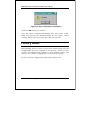
User Accounts Management........................................... 172
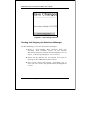
Saving Changes ................................................................ 175
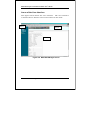
Factory Reset.................................................................... 177
USING WEB-BASED MANAGEMENT ................................ 178
Advanced Setup................................................................ 208
Layer 3 IP Networking....................................................... 215
IP Multicasting ................................................................. 237
Port Mirroring ................................................................... 251
Priority ............................................................................. 253
Filtering............................................................................ 256
Forwarding ....................................................................... 259
Spanning Tree .................................................................. 268
Link Aggregation............................................................... 274
Utilities............................................................................. 277
Network Monitoring .......................................................... 287
Technical Specifications ...................................................... 316
Understanding and Troubleshooting the Spanning Tree
Protocol............................................................................... 319
Blocking State................................................................ 320
Listening State ............................................................... 322
Learning State................................................................ 324
Forwarding State............................................................ 326
Disabled State................................................................ 328
Troubleshooting STP......................................................... 330
Spanning Tree Protocol Failure ...................................... 330
Full/Half Duplex Mismatch............................................ 331
Unidirectional Link ........................................................ 332
Packet Corruption .......................................................... 334
Resource Errors ............................................................. 334
xi
Identifying a Data Loop .................................................. 335
Avoiding Trouble ............................................................ 335
Brief Review of Bitwise Logical Operations........................... 342
Index................................................................................... 344
xii
DES-3326S Layer 3 Fast Ethernet Switch User’s Guide
1
I NTRODUCTION
This section describes the Layer 3 functionality and Layer 2
and Layer 3 features of the DES-3326S. Some background
information about Ethernet/Fast Ethernet, Gigabit Ethernet,
and switching technology is presented. This is intended for
readers who may not be familiar with the concepts of layered
switching and routing but is not intended to be a complete or
in-depth discussion.
Layer 3 Switching
Layer 3 switching is the integration of two proven technologies:
switching and routing. In fact, Layer 3 switches are running
the same routing routines and protocols as traditional routers.
The main difference between traditional routing and Layer 3
switching is the addition of a group of Layer 2 switching
domains and the execution of routing routines for most
packets via an ASIC – in hardware instead of software.
Where a traditional router would have one, or at best a few,
Fast Ethernet ports, the DES-3326S Layer 3 switch has 24
Fast Ethernet ports and optionally, 2 Gigabit Ethernet ports.
Where a traditional router would have one or two high-speed
serial WAN connections, the DES-3326S relies upon a Fast
13
DES-3326S Layer 3 Fast Ethernet Switch User’s Guide
Ethernet port to connect to a separate device, which in turn,
connects the network to a WAN or the Internet.
The DES-3326S can be thought of as 24 Fast Ethernet Layer 2
switching domains with a wire-speed router between each
domain. It can be deployed in a network between a traditional
router and the intranetwork. The traditional router and its
associated WAN interface would then handle routing between
the intranetwork and the WAN (the Internet, for example) while
the Layer 3 switch would handle routing within the LAN
(between the Fast Ethernet Layer 2 domains). Any installed
Layer 2 switches, and indeed the entire subnetting scheme,
would remain in place.
The DES-3326S can also replace key traditional routers for
data centers and server farms, routing between these locations
and the rest of the network, and providing 24 ports of Layer 2
switching performance combined with wire-speed routing.
Backbone routers can also be replaced with DES-3326S and a
series of DES-3326S could be linked via the optional Gigabit
Ethernet ports. Routers that service WAN connections would
remain in place, but would now be removed from the backbone
and connected to the DES-3326S via an Ethernet/Fast
Ethernet port. The backbone itself could be migrated to
Gigabit Ethernet, or faster technologies as they become
available.
The DES-3326S accomplishes two objectives. First as a tool to
provide high-performance access to enterprise data servers and
infrastructure, and second, to enhance the performance of
network equipment already installed. Many network segments
display poor performance, but the Ethernet wire is only
carrying a fraction of its total traffic capacity. The problem is
not necessarily the network, but the ability of the connected
devices utilize the full capacity of the network. The DES3326S can eliminate network bottlenecks to high-traffic areas,
14
Introduction
DES-3326S Layer 3 Fast Ethernet Switch User’s Guide
and improve the utilization of the network’s installed
bandwidth.
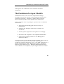
The Functions of a Layer 3 Switch
Traditional routers, once the core components of large
networks, became an obstacle to the migration toward nextgeneration networks. Attempts to make software-based
routers forward packets more quickly were inadequate.
A layer 3 switch does everything to a packet that a traditional
router does:
•
Determines forwarding path based on Layer 3
information
•
Validates the integrity of the Layer 3 header via
checksum
•
Verifies packet expiration and updates accordingly
•
Processes and responds to any optional information
•
Updates forwarding statistics in the Management
Information Base
A Layer 3 switch can be placed anywhere within a network core
or backbone, easily and cost-effectively replacing the
traditional collapsed backbone router. The DES-3326S Layer 3
switch communicates with a WAN router using a standard
Ethernet/Fast Ethernet port. Multiple DES-3326S switches
can be linked via the optional, 2-port Gigabit Ethernet module.
15
DES-3326S Layer 3 Fast Ethernet Switch User’s Guide
Features
The DES-3326S Switch was designed for easy installation and
high performance in an environment where traffic on the
network and the number of users increase continuously.
Switch features include:
Ports
•
24 high performance NWay ports all operating at 10/100
Mbps with Auto-MDIX function for connecting to end
stations, servers and hubs.
•
All ports can auto-negotiate (NWay) between 10Mbps/
100Mbps, half-duplex or full duplex and flow control for
half-duplex ports.
•
One front panel slide-in module interface for a 2-port
1000BASE-SX, 1000BASE-LX, 1000BASE-T, 100BASEFX, GBIC or 1-port GBIC & Stack module.
•
RS-232 DCE Diagnostic port (console port) for setting up
and managing the Switch via a connection to a console
terminal or PC using a terminal emulation program.
Performance Features
Layer 2 Features
•
16
8.8 Gbps switching fabric capacity
Introduction
DES-3326S Layer 3 Fast Ethernet Switch User’s Guide
•
Store and forward switching scheme.
•
Full and half-duplex for both 10Mbps and 100Mbps
connections. The front-port Gigabit Ethernet module
operates at full-duplex only. Full-duplex allows the
switch port to simultaneously transmit and receive data,
and only works with connections to full-duplex capable
end stations and switches. Connections to hubs must
take place at half-duplex.
•
Supports IEEE 802.3x flow control for full-duplex mode
ports.
•
Supports Back-pressure flow control for half-duplex
mode ports.
•
Auto-polarity detection and correction of incorrect
polarity on the transmit and receive twisted-pair at each
port.
•
IEEE 802.3z compliant for all Gigabit ports (optional
module).
•
IEEE 802.3x compliant Flow Control support for all
Gigabit ports (optional module).
•
IEEE 802.3ab compliant for 1000BASE-T (Copper)
Gigabit ports (optional module).
•
Data forwarding rate 14,880 pps per port at 100% of
wire-speed for 10Mbps speed.
•
Data forwarding rate 148,800 pps per port at 100% of
wire-speed for 100Mbps speed.
•
Data filtering rate eliminates all error packets, runts, etc.
at 14,880 pps per port at 100% of wire-speed for
10Mbps speed.
17
DES-3326S Layer 3 Fast Ethernet Switch User’s Guide
•
Data filtering rate eliminates all error packets, runts, etc.
at 148,800 pps per port at 100% of wire-speed for
100Mbps speed.
•
8K active MAC address entry table per device with
automatic learning and aging (10 to 9999 seconds).
•
8 MB packet buffer per device.
•
Broadcast and Multicast storm filtering.
•
Supports Port Mirroring.
•
Supports Port Trunking – up to six trunk groups (each
consisting of up to eight ports) may be set up.
•
802.1D Spanning Tree support.
•
802.1Q Tagged VLAN support – up to 63 User-defined
VLANs per device (one VLAN is reserved for internal use).
•
GVRP – (GARP VLAN Registration Protocol) support for
dynamic VLAN registration.
•
802.1p Priority support with 4 priority queues.
•
IGMP Snooping support.
Layer 3 Switch Features
•
Wire speed IP forwarding.
•
Hardware-based Layer 3 IP switching.
•
IP packet forwarding rate of 6.6 Mpps.
•
2K active IP address entry table per device.
18
Introduction
DES-3326S Layer 3 Fast Ethernet Switch User’s Guide
•
Supports RIP – (Routing Information Protocol) version I
and II.
•
Supports OSPF − (Open Shortest Path First)
•
Supports MD5 and Password OSPF Packet
Authentication
•
Supports IP version 4.
•
IGMP version 1 and 2 support (RFC 1112 and RFC
2236).
•
Supports PIM Dense Mode.
•
Supports DVMRP.
•
Supports IP multi-netting.
•
Supports IP packet de-fragmentation.
•
Supports 802.1D frame support.
Traffic Classification and Prioritization
•
Based on 802.1p priority bits
•
4 priority queues
Management
•
RS-232
console
port
for
out-of-band
management via a console terminal or PC.
•
Spanning Tree Algorithm Protocol for creation of
alternative backup paths and prevention of network
loops.
network
19
DES-3326S Layer 3 Fast Ethernet Switch User’s Guide
•
SNMP v.1 Agent.
•
Fully configurable either in-band or out-of-band control
via SNMP based software.
•
Flash memory for software upgrades. This can be done
in-band via TFTP or out-of-band via the console.
•
Built-in SNMP management:
Bridge MIB (RFC 1493)
MIB-II (RFC 1213)
Mini-RMON MIB (RFC 1757) – 4 groups
CIDR MIB (RFC 2096), except IP Forwarding Table.
802.1p MIB (RFC 2674).
RIP MIB v2 (RFC 1724).
IF MIB (RFC 2233)
Ether-Like MIB (RFC 1643)
OSPF MIB (RFC 1850)
•
Supports Web-based management.
•
CLI management support
•
TFTP support.
•
BOOTP support.
•
BOOTP Relay Agent.
•
IP filtering on the management interface.
20
Introduction
DES-3326S Layer 3 Fast Ethernet Switch User’s Guide
•
DCHP Client support.
•
DCHP Relay Agent.
•
DNS Relay Agent.
•
Password enabled.
Switch Stacking
The DES-3326 can be used as a standalone or stacked switch
− using the optional stacking module. Up to 6 Switches may be
stacked and managed as a unit with a single IP address.
Management for the entire stack is done through the Master
Switch.
You may add Switches later as needed.
Fast Ethernet Technology
100Mbps Fast Ethernet (or 100BASE-T) is a standard specified
by the IEEE 802.3 LAN committee. It is an extension of the
10Mbps Ethernet standard with the ability to transmit and
receive data at 100Mbps, while maintaining the Carrier Sense
Multiple Access with Collision Detection (CSMA/CD) Ethernet
protocol.
21
DES-3326S Layer 3 Fast Ethernet Switch User’s Guide
Gigabit Ethernet Technology
Gigabit Ethernet is an extension of IEEE 802.3 Ethernet
utilizing the same packet structure, format, and support for
CSMA/CD protocol, full duplex, flow control, and management
objects, but with a tenfold increase in theoretical throughput
over 100Mbps Fast Ethernet and a one hundred-fold increase
over 10Mbps Ethernet. Since it is compatible with all 10Mbps
and 100Mbps Ethernet environments, Gigabit Ethernet
provides a straightforward upgrade without wasting a
company’s existing investment in hardware, software, and
trained personnel.
Gigabit Ethernet enables fast optical fiber connections and
Unshielded Twisted Pair connections to support video
conferencing, complex imaging, and similar data-intensive
applications. Likewise, since data transfers occur 10 times
faster than Fast Ethernet, servers outfitted with Gigabit
Ethernet NIC’s are able to perform 10 times the number of
operations in the same amount of time.
22
Introduction
DES-3326S Layer 3 Fast Ethernet Switch User’s Guide
2
U NPACKING AND S ETUP
This chapter provides unpacking and setup information for the
Switch.
Unpacking
Open the shipping carton of the Switch and carefully unpack
its contents. The carton should contain the following items:
♦ One DES-3226 24-port Fast Ethernet Layer 3 Switch
♦ Mounting kit: 2 mounting brackets and screws
♦ Four rubber feet with adhesive backing
♦ One AC power cord
♦ This User’s Guide with Registration Card
If any item is found missing or damaged, please contact your
local D-Link reseller for replacement.
23
DES-3326S Layer 3 Fast Ethernet Switch User’s Guide
Installation
Use the following guidelines when choosing a place to install
the Switch:
♦ The surface must support at least 3 kg.
♦ The power outlet should be within 1.82 meters (6 feet) of
the device.
♦ Visually inspect the power cord and see that it is secured
to the AC power connector.
♦ Make sure that there is proper heat dissipation from and
adequate ventilation around the switch. Do not place
heavy objects on the switch.
Desktop or Shelf Installation
When installing the Switch on a desktop or shelf, the rubber
feet included with the device should first be attached. Attach
these cushioning feet on the bottom at each corner of the
device. Allow adequate space for ventilation between the device
and the objects around it.
24
Unpacking and Setup
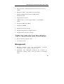
DES-3326S Layer 3 Fast Ethernet Switch User’s Guide
Figure 2-1. Installing rubber feet for desktop installation
Rack Installation
The DES-3326S can be mounted in an EIA standard-sized, 19inch rack, which can be placed in a wiring closet with other
equipment. To install, attach the mounting brackets on the
switch’s side panels (one on each side) and secure them with
the screws provided.
Figure 2- 2A. Attaching the mounting brackets to the switch
25
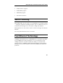
DES-3326S Layer 3 Fast Ethernet Switch User’s Guide
Then, use the screws provided with the equipment rack to
mount the switch on the rack.
Figure 2-2B. Installing the switch on an equipment rack
Power on
The DES-3326S switch can be used with AC power supply
100-240 VAC, 50 - 60 Hz. The power switch is located at the
rear of the unit adjacent to the AC power connector and the
system fan. The switch’s power supply will adjust to the local
power source automatically and may be turned on without
having any or all LAN segment cables connected.
After the power switch is turned on, the LED indicators should
respond as follows:
26
Unpacking and Setup
DES-3326S Layer 3 Fast Ethernet Switch User’s Guide
♦ All LED indicators will momentarily blink. This blinking
of the LED indicators represents a reset of the system.
♦ The power LED indicator is always on after the power is
turned ON.
♦ The console LED indicator will blink while the Switch
loads onboard software and performs a self-test. will
remain ON if there is a connection at the RS-232 port,
otherwise this LED indicator is OFF.
♦ The 100M LED indicator may remain ON or OFF
depending on the transmission speed.
Power Failure
As a precaution in the event of a power failure, unplug the
switch. When power is resumed, plug the switch back in.
27
DES-3326S Layer 3 Fast Ethernet Switch User’s Guide
3
I DENTIFYING E XTERNAL
C OMPONENTS
This chapter describes the front panel, rear panel, optional
plug-in modules, and LED indicators of the DES-3326S.
Front Panel
The front panel of the Switch consists of LED indicators, an
RS-232 communication port, a slide-in module slot, and 24
(10/100 Mbps) Ethernet/Fast Ethernet ports.
Figure 3-1. Front panel view of the Switch
♦ Comprehensive LED indicators display the status of the
switch and the network (see the LED Indicators section
below).
♦ An RS-232 DCE console port for setting up and managing
the switch via a connection to a console terminal or PC
using a terminal emulation program.
28
Identifying External Components
DES-3326S Layer 3 Fast Ethernet Switch User’s Guide
♦ A front-panel slide-in module slot for Gigabit Ethernet
ports can accommodate a 2-port 1000BASE-T Gigabit
Ethernet module, a 2-port 1000BASE-SX Gigabit
Ethernet module, a 2-port 1000BASE-LX Gigabit
Ethernet module, or a 2-port GBIC-based Gigabit
Ethernet module.
♦ Twenty-four high-performance, NWay Ethernet ports all
of which operate at 10/100 Mbps with Auto-MDIX
function for connections to end stations, servers and
hubs. All ports can auto-negotiate between 10Mbps or
100Mbps, full or half duplex, and flow control.
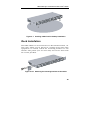
Rear Panel
The rear panel of the switch contains an AC power connector.
Figure 3-2. Rear panel view of the Switch
♦ The AC power connector is a standard three-pronged
connector that supports the power cord. Plug-in the
female connector of the provided power cord into this
socket, and the male side of the cord into a power outlet.
Supported input voltages range from 100 ~ 240 VAC at
50 ~ 60 Hz.
Identifying External Components
29
DES-3326S Layer 3 Fast Ethernet Switch User’s Guide
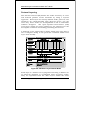
Side Panels
The right side panel of the Switch contains two system fans
(see the top part of the diagram below). The left side panel
contains heat vents.
Figure 3-4. Side panel views of the Switch
♦ The system fans are used to dissipate heat. The sides of
the system also provide heat vents to serve the same
purpose. Do not block these openings, and leave at least
6 inches of space at the rear and sides of the switch for
proper ventilation. Be reminded that without proper heat
dissipation and air circulation, system components might
overheat, which could lead to system failure.
Optional Plug-in Modules
The DES-3326S 24-port Fast Ethernet Layer 3 Switch is able to
accommodate a range of optional plug-in modules in order to
increase functionality and performance. These modules must
be purchased separately.
30
Identifying External Components
DES-3326S Layer 3 Fast Ethernet Switch User’s Guide
100BASE-FX Fiber Module (2Km/15Km)
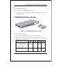
Figure 3-5. 100BASE-FX two-port module
♦
Front-panel module.
♦
Two 100BASE-FX (with SC type connector) Fiber ports.
♦
Fully compliant with IEEE802.3u.
♦
Support Full-duplex operation only.
♦
IEEE 802.3x compliant Flow Control support for full-duplex.
1000BASE-T Module
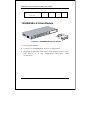
Figure 3-6. 1000BASE-TX two-port module
Identifying External Components
31
DES-3326S Layer 3 Fast Ethernet Switch User’s Guide
♦
Front-panel module.
♦
Connects to 1000BASE-T devices.
♦
Supports Category 5e UTP or STP cable connections of up
to 100 meters.
1000BASE-SX Fiber Module
Figure 3-7. 1000BASE-SX two-port module
♦ Front-panel module.
♦ Connects to 1000BASE-SX devices at full-duplex.
♦ Allows connections using multi-mode fiber optic cable in the
following configurations:
Modal bandwidth
62.5µm
62.5µm
50µm
50µm
160
200
400
500
220
275
500
550
(min. overfilled launch)
Unit: MHz*km
Operating distance
Unit: meters
32
Identifying External Components
DES-3326S Layer 3 Fast Ethernet Switch User’s Guide
Channel insertion loss
2.33
2.53
3.25
3.43
Unit: dB
1000BASE-LX Fiber Module
Figure 3-8. 1000BASE-LX two-port module
♦ Front-panel module.
♦ Connects to 1000BASE-LX devices at full-duplex.
♦ Supports multi-mode fiber-optic cable connections of up to
550 meters or 5 km single-mode fiber-optic cable
connections.
Identifying External Components
33
DES-3326S Layer 3 Fast Ethernet Switch User’s Guide
GBIC Two-Port Module
Figure 3-9. GBIC two-port module
♦ Front-panel module.
♦ Connects to GBIC devices at full duplex only.
♦ Allows multi-mode fiber optic connections of up to 550 m
(SX and LX) and single-mode fiber optic connections of up to
5 km (LX only). GBIC modules are available in –SX and –LX
fiber optic media.
♦ IEEE 802.3x compliant Flow Control for full-duplex.
Stacking Module with GBIC Port
Figure 3-10. Stacking Module with one GBIC port
34
Identifying External Components
DES-3326S Layer 3 Fast Ethernet Switch User’s Guide
GBIC Port
♦ Front-panel module.
♦ One Stacking port and one GBIC fiber port
♦ Connects to GBIC devices at full duplex only.
♦ Allows multi-mode fiber optic connections of up to 550 m
(SX and LX) and single-mode fiber optic connections of up to
5 km (LX only). GBIC modules are available in –SX and –LX
fiber optic media.
♦ IEEE 802.3x compliant Flow Control for full-duplex.
Stacking Port
♦ One transmitting port and one receiving port.
♦ Use the connector of IEEE 1394b.
♦ Data rate up to 1250 Mbps
♦ 7-segment LED display to indicate switch ID number within
the switch stack.
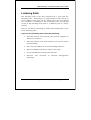
The optional Stacking Module allows up to 6 DES-3326S
Switches to be interconnected via their individual Stacking
Modules. This forms a 6 switch stack that can then be
managed and configured as thought the entire stack were a
single switch. The switch stack is then accessed through a
single IP address or alternatively, through the master switch’s
serial port (via the management station’s console and the
switch’s Command Line Interface).
Identifying External Components
35
DES-3326S Layer 3 Fast Ethernet Switch User’s Guide
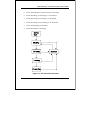
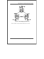
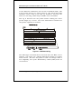
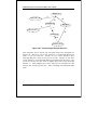
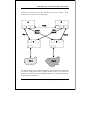
Figure 3-11. Up to 6 Switches in a Switch Stack
The stacking ports are marked IN and OUT. The IEEE 1394
compliant cable must be connected from an IN port on one
switch to an OUT port on the next switch in the stack. The last
two switches (at the top and bottom of the stack) must also be
connected from the IN port on one switch to the OUT port on
the other switch. In this way, a loop is made such that all of
the switches in the switch stack have the IN stacking port
connected to another switch’s OUT stacking port.
The Stacking Module’s LED indicators are described below.
36
Identifying External Components
DES-3326S Layer 3 Fast Ethernet Switch User’s Guide
Switch LED Indicators
The LED indicators of the Switch include Power, Console, and
Link/Act. The following shows the LED indicators for the
Switch along with an explanation of each indicator.
Figure 3-12. The LED Indicators
♦ Power This indicator on the front panel should be lit
during the Power-On Self Test (POST). It will light green
approximately 2 seconds after the switch is powered on to
indicate the ready state of the device.
♦ Console This indicator is lit green when the switch is
being
managed
via
out-of-band/local
console
management through the RS-232 console port using a
straight-through serial cable.
♦ Act/Link These indicators are located to the left and right of each
port. They are lit when there is a secure connection (or link) to a
device at any of the ports. The LEDs blink whenever there is reception
or transmission (i.e. Activity--Act) of data occurring at a port.
Stacking Module LED Indicators
The switch’s current order in the switch stack is also displayed
on the Stacking Module’s front panel − under the STACK NO.
heading:
Identifying External Components
37
DES-3326S Layer 3 Fast Ethernet Switch User’s Guide
Figure 3-13. Stacking Module LED Indicators
The Link and Act LEDs have the same function as the
corresponding LEDs for the switch’s Ethernet ports. The Link
LED lights to confirm a valid link, while the ACT LED blinks to
indicate activity on the link.
The Stack No. seven-segment LED displays the Unit number
assigned to the switch. A 0 (a zero) in the display indicates
that the stacking module is in the process of determining the
stack status and has not yet resolved the switch’s Unit number.
The stacking order can be automatically configured using the
switch’s MAC address − the lower the numerical value of a
given switch’s MAC address, the lower the number in the
stacking order the switch will be assigned. The switch with the
lowest MAC address, will then become the Master Switch. This
is the Stacking Module’s default mode.
Alternatively, the stacking order can be manually assigned
using the console’s Command Line Interface (CLI).
38
Identifying External Components
DES-3326S Layer 3 Fast Ethernet Switch User’s Guide
4
C ONNECTING T HE
S WITCH
This chapter describes how to connect the DES 3226 to your
Fast Ethernet network.
Switch to End Node
End nodes include PCs outfitted with a 10, 100 or 10/100
Mbps RJ-45 Ethernet/Fast Ethernet Network Interface Card
(NIC) and most routers. The RJ-45 UTP ports on NICs and most
routers are MDI-II. When using a normal straight-through
cable, an MDI-II port must connect to an MDI-X port.
An end node can be connected to the Switch via a two-pair
Category 3, 4, 5 UTP/STP straight cable (be sure to use
Category 5e UTP or STP cabling for 100 Mbps Fast Ethernet
connections). The end node should be connected to any of the
twenty-four ports (2x - 24x) of the DES-3226 or to either of the
two 100BASE-TX ports on the front-panel module that came
preinstalled on the switch.
Connecting The Switch
39
DES-3326S Layer 3 Fast Ethernet Switch User’s Guide
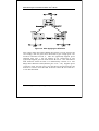
Figure 4-1. Switch connected to an End Node
The LED indicators for the port the end node is connected to
are lit according to the capabilities of the NIC. If LED indicators
are not illuminated after making a proper connection, check
the PC’s LAN card, the cable, switch conditions, and
connections.
The following LED indicator states are possible for an end node
to switch connection:
1. The 100 LED indicator comes ON for a 100 Mbps and
stays OFF for 10 Mbps.
2. The Link/Act LED indicator lights up upon hooking up a
PC that is powered on.
Switch to Hub or Switch
These connections can be accomplished at any port in either
straight-through cable or a crossover cable because the switch
supports Auto-MDIX function.
♦ A 10BASE-T hub or switch can be connected to the
Switch via a two-pair Category 3, 4 or 5 UTP/STP cable.
♦ A 100BASE-TX hub or switch can be connected to the
Switch via a two-pair Category 5e UTP/STP cable.
40
Connecting The Switch
DES-3326S Layer 3 Fast Ethernet Switch User’s Guide
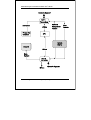
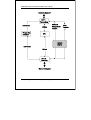
Switch Stack Connections
Up to 6 DES-3326S switches can be stacked, using the
optional stacking module, into a switch stack that can then be
configured and managed as a single unit. The Web-based
Management agent of the Master Switch can configure and
manage all of the switches in a switch stack − using a single IP
address (the IP address of the Master Switch).
The Command Line Interface (CLI) can be also be used to
manage and configure all of the switches in a switch stack −
from the serial port on the master switch.
The CLI can also be used to configure and manage the switch
stack via the TELNET protocol − using a single IP address (the
IP address of the Master Switch).
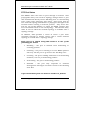
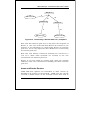
The stacking ports are marked IN and OUT. The IEEE 1394
compliant cable must be connected from an IN port on one
switch to an OUT port on the next switch in the stack. The last
two switches (at the top and bottom of the stack) must also be
connected from the IN port on one switch to the OUT port on
the other switch. In this way, a loop is made such that all of
the switches in the switch stack have the IN stacking port
connected to another switch’s OUT stacking port.
An example stacking port interconnection is shown below:
Connecting The Switch
41
DES-3326S Layer 3 Fast Ethernet Switch User’s Guide
Figure 4-. Switch Stack connections between optional stacking
modules
10BASE-T Device
For a 10BASE-T device, the Switch’s LED indicators should
display the following:
♦ 100 LED speed indicator is OFF.
♦ Link/Act indicator is ON.
42
Connecting The Switch
DES-3326S Layer 3 Fast Ethernet Switch User’s Guide
100BASE-TX Device
For a 100BASE-TX device, the Switch’s LED indicators should
display the following:
♦
100 LED speed indicator is ON.
♦
Link/Act is ON.
Connecting The Switch
43
DES-3326S Layer 3 Fast Ethernet Switch User’s Guide
5
S WITCH M ANAGEMENT
AND O PERATING
C ONCEPTS
This chapter discusses many of the concepts and features used
to manage the switch, as well as the concepts necessary for the
user to understand the functioning of the switch. Further, this
chapter
explains many important points regarding these
features.
Configuring the switch to implement these concepts and make
use of its many features is discussed in detail in the next
chapters.
Local Console Management
A local console is a terminal or a workstation running a
terminal emulation program that is connected directly to the
switch via the RS-232 console port on the front of the switch.
A console connection is referred to as an ‘Out-of-Band’
connection, meaning that console is connected to the switch
using a different circuit than that used for normal network
communications. So, the console can be used to set up and
manage the switch even if the network is down.
44
Switch Management and Operating Concepts
DES-3326S Layer 3 Fast Ethernet Switch User’s Guide
Local console management uses the terminal connection to
operate the console program built-in to the switch (see Chapter
6 – Using the Console Interface). A network administrator can
manage, control and monitor the switch from the console
program.
The DES-3326S contains a CPU, memory for data storage,
flash memory for configuration data, operational programs, and
SNMP agent firmware. These components allow the switch to
be actively managed and monitored from either the console
port or the network itself (out-of-band, or in-band).
Diagnostic (console) port (RS-232 DCE)
Out-of-band management requires connecting a terminal, such
as a VT-100 or a PC running a terminal emulation program
(such as HyperTerminal, which is automatically installed with
Microsoft Windows) a to the RS-232 DCE console port of the
Switch. Switch management using the RS-232 DCE console
port is called Local Console Management to differentiate it from
management performed via management platforms, such as DView, HP OpenView, etc. Web-based Management describes
management of the switch performed over the network (in-band)
using the switch’s built-in Web-based management program
(see Chapter 7 – Web-based Network Management).
The
operations to be performed and the facilities provided by these
two built-in programs are identical.
The console port is set at the factory for the following
configuration:
•
Baud rate:
9,600
•
Data width:
8 bits
•
Parity:
none
•
Stop bits:
1
•
Flow Control
None
Switch Management and Operating Concepts
45
DES-3326S Layer 3 Fast Ethernet Switch User’s Guide
Make sure the terminal or PC you are using to make this
connection is configured to match these settings.
If you are having problems making this connection on a PC,
make sure the emulation is set to VT-100. If you still don’t
see anything, try hitting <Ctrl> + r to refresh the screen.
Managing Switch Stacks
The Switch is designed to be stacked in stacks of up to six
Switches, all managed as a single unit with a single IP address.
The stack order is hardware-determined, that is, the unique
MAC address of each Switch determines where the Switch
stands in the stack order. This fact can be taken into account
when you are placing the Switches in the equipment rack.
Administrators may find it convenient to place the Switches in
the rack in the same order they appear logically in the Switch
stack. However, you also may prefer to override the auto-detect
stack order feature if for example, you add Switches to a stack
that is already in place. Regardless of the method used to
determine Switch stack order, remember some important
points:
46
•
All management of all the Switches in the stack is done
through the Master Switch.
•
It is recommended that the Master Switch be used to
uplink to the Ethernet backbone.
•
If any Switch in the stack fails, all Switches will need to
be rebooted upon correcting the failure.
•
If a new Master is elected, all Switches in the stack
must rebooted. This includes situations where the new
Master is determined by MAC address, for example, if
the original Master is removed from the stack.
Switch Management and Operating Concepts
DES-3326S Layer 3 Fast Ethernet Switch User’s Guide
•
The Master Switch can be chosen automatically. Switch
software auto-detects the MAC address of each Switch
in the stack. The Switch with the lowest value MAC
address is elected to function as the Master. The
remaining Switches are ordered according to the relative
value of their respective MAC addresses (see the
following example).
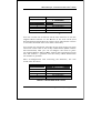
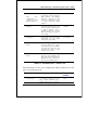
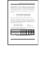
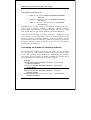
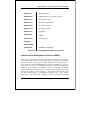
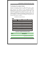
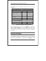
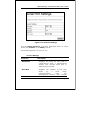
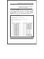
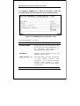
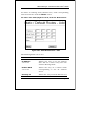
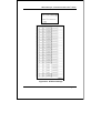
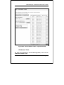
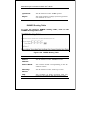
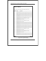
Determining the Switch Stack Order
Using the auto stacking mode, five MAC addresses appear in
the order listed in the table below:
Stack Order
1(Master)
2
3
4
5
6
MAC Address
001122334451
001122334452
001122334453
001122334454
001122334455
Not in use
Table 5-1. Switch Stack Order − First
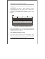
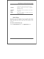
Now let us suppose you wish to add another Switch to this
stack. The new Switch has a MAC address 001122334450.
After rebooting all the Switches in the stack, the newly added
Switch becomes the Master Switch. The new automatically
determined stack order becomes:
Switch Management and Operating Concepts
47
DES-3326S Layer 3 Fast Ethernet Switch User’s Guide
Stack Order
1(added Switch)
2(original Master)
3
4
5
6
MAC Address
001122334450
001122334451
001122334452
001122334453
001122334454
001122334455
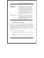
Table 5-2. Switch Stack Order − Second
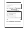
You can override the automatic stack order selection to use the
original Master Switch as the Master of the new stack (read
Switch Stacking Information in Chapter 6 for information on how
to override the stack order auto-detect function).
To override the automatic selection of the stack order you must
attach the serial cable to the newly added Switch (MAC address
001122334450). Now you can reconfigure the stack to place
the original Master Switch (MAC address 001122334451) again
into the number 1 position and the newly added Switch into
the number 6 position.
After reconfiguration and restarting the Switches, the new
stack order becomes:
Stack Order
1(original Master)
2
3
4
5
6 (added Switch)
MAC Address
001122334451
001122334452
001122334453
001122334454
001122334455
001122334450
Table 5-3. Switch Stack Order − Final
48
Switch Management and Operating Concepts
DES-3326S Layer 3 Fast Ethernet Switch User’s Guide
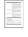
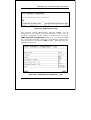
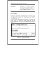
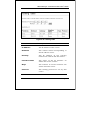
Switch IP Address
Each Switch must be assigned its own IP Address, which is
used for communication with an SNMP network manager or
other TCP/IP application (for example BOOTP, TFTP). The
switch’s default IP address is 10.90.90.90. You can change the
default Switch IP Address to meet the specification of your
networking address scheme.
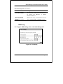
The switch is also assigned a unique MAC address by the
factory. This MAC address cannot be changed, and can be
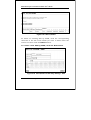
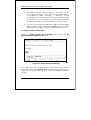
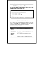
found from the initial boot console screen – shown below.
Figure 5-1. Console Boot Screen
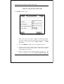
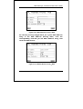
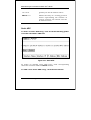
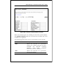
The switch’s MAC address can also be found from the console
program under the Switch Information menu item, as shown
below.
Switch Management and Operating Concepts
49
DES-3326S Layer 3 Fast Ethernet Switch User’s Guide
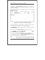
Setting an IP Address
The IP address for the switch must be set before it can be
managed with the web-based manager. The switch IP address
may be automatically set using BOOTP or DHCP protocols, in
which case the actual address assigned to the switch must be
known.
The IP address may alternatively be set using the
Command Line Interface (CLI) over the console serial port
as follows:
1. Starting at the command line prompt DES3326S4#
− enter the commands config ipif System
ipaddress
xxx.xxx.xxx.xxx/yyy.yyy.yyy.yyy.
Where the x’s represent the IP address to be
assigned to the IP interface named System and the
y’s represent the corresponding subnet mask.
2. Alternatively, you can enter DES3326S4# − enter
the commands config ipif system ipaddress
xxx.xxx.xxx.xxx/z. Where the x’s represent the IP
address to be assigned to the IP interface named
System and the z represents the corresponding
number of subnets in CIDR notation.
Using this method, the switch can be assigned an IP address
and subnet mask which can then be used to connect a
management station to the switch’s web-based management
agent.
Traps
Traps are messages that alert you of events that occur on the
Switch. The events can be as serious as a reboot (someone
50
Switch Management and Operating Concepts
DES-3326S Layer 3 Fast Ethernet Switch User’s Guide
accidentally turned OFF the Switch), or less serious like a port
status change. The Switch generates traps and sends them to
the network manager (trap recipient).
Trap recipients are special users of the network who are given
certain rights and access in overseeing the maintenance of the
network. Trap recipients will receive traps sent from the Switch;
they must immediately take certain actions to avoid future
failure or breakdown of the network.
You can also specify which network managers may receive
traps from the Switch by entering a list of the IP addresses of
authorized network managers. Up to four trap recipient IP
addresses, and four corresponding SNMP community strings
can be entered.
SNMP community strings function like passwords in that the
community string entered for a given IP address must be used
in the management station software, or a trap will be sent.
The following are trap types the switch can send to a trap
recipient:
•
Cold Start This trap signifies that the Switch has
been powered up and initialized such that software
settings are reconfigured and hardware systems are
rebooted. A cold start is different from a factory reset
in that configuration settings saved to non-volatile
RAM used to reconfigure the switch.
•
Warm Start This trap signifies that the Switch has
been rebooted, however the POST (Power On Self-Test)
is skipped.
•
Authentication Failure
This trap signifies that
someone has tried to logon to the switch using an
invalid SNMP community string. The switch
automatically stores the source IP address of the
unauthorized user.
Switch Management and Operating Concepts
51
DES-3326S Layer 3 Fast Ethernet Switch User’s Guide
•
New Root This trap indicates that the Switch has
become the new root of the Spanning Tree, the trap is
sent by the switch soon after its election as the new
root. This implies that upon expiration of the Topology
Change Timer the new root trap is sent out
immediately after the Switch’s election as the new
root.
•
Topology Change (STP) A Topology Change trap is
sent by the Switch when any of its configured ports
transitions from the Learning state to the Forwarding
state, or from the Forwarding state to the Blocking
state. The trap is not sent if a new root trap is sent for
the same transition.
•
Link Up This trap is sent whenever the link of a port
changes from link down to link up.
•
Link Down This trap is sent whenever the link of a
port changes from link up to link down.
SNMP
The Simple Network Management Protocol (SNMP) is an OSI
layer 7 (the application layer) protocol for remotely monitoring
and configuring network devices.
SNMP enables network
management stations to read and modify the settings of
gateways, routers, switches, and other network devices. SNMP
can be used to perform many of the same functions as a
directly connected console, or can be used within an integrated
network management software package such as DView.
SNMP performs the following functions:
52
Switch Management and Operating Concepts
DES-3326S Layer 3 Fast Ethernet Switch User’s Guide
•
•
•
Sending and receiving SNMP packets through the IP
protocol.
Collecting information about the status and current
configuration of network devices.
Modifying the configuration of network devices.
The DES-3326S has a software program called an ‘agent’ that
processes SNMP requests, but the user program that makes
the requests and collects the responses runs on a management
station (a designated computer on the network). The SNMP
agent and the user program both use the UDP/IP protocol to
exchange packets.
Authentication
The authentication protocol ensures that both the router SNMP
agent and the remote user SNMP application program discard
packets from unauthorized users.
Authentication is
accomplished using ‘community strings’, which function like
passwords. The remote user SNMP application and the router
SNMP must use the same community string.
SNMP
community strings of up to 20 characters may be entered
under the Remote Management Setup menu of the console
program.
Traps
Traps are messages that alert network personnel of events that
occur on the Switch. The events can be as serious as a reboot
(someone accidentally turned OFF the Switch), or less serious
like a port status change. The Switch generates traps and
sends them to the trap recipient (or network manager).
Trap recipients are special users of the network who are given
certain rights and access in overseeing the maintenance of the
network. Trap recipients will receive traps sent from the Switch;
Switch Management and Operating Concepts
53
DES-3326S Layer 3 Fast Ethernet Switch User’s Guide
they must immediately take certain actions to avoid future
failure or breakdown of the network.
You can also specify which network managers may receive
traps from the Switch by entering a list of the IP addresses of
authorized network managers. Up to four trap recipient IP
addresses, and four corresponding SNMP community strings
can be entered.
SNMP community strings function like passwords in that the
community string entered for a given IP address must be used
in the management station software, or a trap will be sent.
The following are trap types the switch can send to a trap
recipient:
54
•
Cold Start This trap signifies that the Switch
has been powered up and initialized such
that software settings are reconfigured and
hardware systems are rebooted. A cold start
is different from a factory reset in that
configuration settings saved to non-volatile
RAM used to reconfigure the switch.
•
Warm Start
This trap signifies that the
Switch has been rebooted, however the POST
(Power On Self-Test) is skipped.
•
Authentication Failure This trap signifies
that someone has tried to logon to the switch
using an invalid SNMP community string. The
switch automatically stores the source IP
address of the unauthorized user.
•
Topology Change A Topology Change trap is
sent by the Switch when any of its configured
ports transitions from the Learning state to
the Forwarding state, or from the Forwarding
state to the Blocking state. The trap is not
Switch Management and Operating Concepts
DES-3326S Layer 3 Fast Ethernet Switch User’s Guide
sent if a new root trap is sent for the same
transition.
•
Link Change Event
This trap is sent
whenever the link of a port changes from link
up to link down or from link down to link up.
•
Port Partition This trap is sent whenever the
port state enters the partition mode (or
automatic partitioning, port disable) when
more than thirty-two collisions occur while
transmitting at 10Mbps or more than sixtyfour collisions occur while transmitting at
100Mbps.
•
Broadcast\Multicast Storm
This trap is
sent whenever the port reaches the threshold
(in packets per second) set globally for the
switch. Counters are maintained for each
port, and separate counters are maintained
for broadcast and multicast packets. The
switch’s default setting is 128 kpps for both
broadcast and multicast packets.
MIBs
Management and counter information are stored in the Switch
in the Management Information Base (MIB). The Switch uses
the standard MIB-II Management Information Base module.
Consequently, values for MIB objects can be retrieved from any
SNMP-based network management software. In addition to the
standard MIB-II, the Switch also supports its own proprietary
enterprise MIB as an extended Management Information Base.
These MIBs may also be retrieved by specifying the MIB’s
Switch Management and Operating Concepts
55
DES-3326S Layer 3 Fast Ethernet Switch User’s Guide
Object-Identity (OID) at the network manager. MIB values can
be either read-only or read-write.
Read-only MIBs variables can be either constants that are
programmed into the Switch, or variables that change while the
Switch is in operation. Examples of read-only constants are
the number of port and type of ports. Examples of read-only
variables are the statistics counters such as the number of
errors that have occurred, or how many kilobytes of data have
been received and forwarded through a port.
Read-write MIBs are variables usually related to usercustomized configurations. Examples of these are the Switch’s
IP Address, Spanning Tree Algorithm parameters, and port
status.
If you use a third-party vendors’ SNMP software to manage the
Switch, a diskette listing the Switch’s propriety enterprise MIBs
can be obtained by request. If your software provides functions
to browse or modify MIBs, you can also get the MIB values and
change them (if the MIBs’ attributes permit the write operation).
This process however can be quite involved, since you must
know the MIB OIDs and retrieve them one by one.
Packet Forwarding
The Switch enters the relationship between destination MAC or
IP addresses and the Ethernet port or gateway router the
destination resides on into its forwarding table.
This
information is then used to forward packets. This reduces the
traffic congestion on the network, because packets, instead of
being transmitted to all ports, are transmitted to the
destination port only. Example: if Port 1 receives a packet
destined for a station on Port 2, the Switch transmits that
packet through Port 2 only, and transmits nothing through the
56
Switch Management and Operating Concepts
DES-3326S Layer 3 Fast Ethernet Switch User’s Guide
other ports. This process is referred to as ‘learning’ the
network topology.
MAC Address Aging Time
The Aging Time affects the learning process of the Switch.
Dynamic forwarding table entries, which are made up of the
source MAC addresses and their associated port numbers, are
deleted from the table if they are not accessed within the aging
time.
The aging time can be from 10 to 1,000,000 seconds with a
default value of 300 seconds. A very long aging time can result
in dynamic forwarding table entries that are out-of-date or no
longer exist. This may cause incorrect packet forwarding
decisions by the switch.
If the Aging Time is too short however, many entries may be
aged out too soon. This will result in a high percentage of
received packets whose source addresses cannot be found in
the forwarding table, in which case the switch will broadcast
the packet to all ports, negating many of the benefits of having
a switch.
Static forwarding entries are not affected by the aging time.
Filtering
The switch uses a filtering database to segment the network
and control communication between segments. It can also filter
packets off the network for intrusion control. Static filtering
entries can be made by MAC Address or IP Address filtering.
Each port on the switch is a unique collision domain and the
switch filters (discards) packets whose destination lies on the
Switch Management and Operating Concepts
57
DES-3326S Layer 3 Fast Ethernet Switch User’s Guide
same port as where it originated. This keeps local packets from
disrupting communications on other parts of the network.
For intrusion control, whenever a switch encounters a packet
originating from or destined to a MAC address or an IP Address
entered into the filter table, the switch will discard the packet.
Some filtering is done automatically by the switch:
•
Dynamic filtering – automatic learning and aging of MAC
addresses and their location on the network. Filtering
occurs to keep local traffic confined to its segment.
•
Filtering done by the Spanning Tree Protocol, which can
filter packets based on topology, making sure that signal
loops don’t occur.
•
Filtering done for VLAN integrity. Packets from a member
of a VLAN (VLAN 2, for example) destined for a device on
another VLAN (VLAN 3) will be filtered.
Some filtering requires the manual entry of information
into a filtering table:
58
•
MAC address filtering – the manual entry of specific MAC
addresses to be filtered from the network. Packets sent
from one manually entered MAC address can be filtered
from the network. The entry may be specified as either a
source, a destination, or both.
•
IP address filtering – the manual entry of specific IP
addresses to be filtered from the network (switch must be
in IP Routing mode). Packets sent from one manually
entered IP address to another can be filtered from the
network. The entry may specified as either a source, a
destination, or both (switch must be in IP Routing mode).
Switch Management and Operating Concepts
DES-3326S Layer 3 Fast Ethernet Switch User’s Guide
Spanning Tree
The IEEE 802.1D Spanning Tree Protocol allows for the
blocking of links between switches that form loops within the
network. When multiple links between switches are detected, a
primary link is established. Duplicated links are blocked from
use and become standby links. The protocol allows for the
duplicate links to be used in the event of a failure of the
primary link. Once the Spanning Tree Protocol is configured
and enabled, primary links are established and duplicated
links are blocked automatically.
The reactivation of the
blocked links (at the time of a primary link failure) is also
accomplished automatically – without operator intervention.
The DES-3326S STP allows two levels of spanning trees to be
configured. The first level constructs a spanning tree on the
links between switches. This is referred to as the Switch or
Global level. The second level is on a port group basis.
Groups of ports are configured as being members of a spanning
tree and the algorithm and protocol are applied to the group of
ports. This is referred to as the Port or VLAN level.
On the switch level, STP calculates the Bridge Identifier for
each switch and then sets the Root Bridge and the Designated
Bridges.
On the port level, STP sets the Root Port and the Designated
Ports.
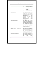
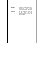
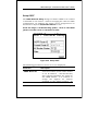
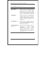
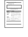
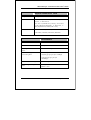
The following are the user-configurable STP parameters for the
switch level:
Parameter
Description
Switch Management and Operating Concepts
Default
Value
59
DES-3326S Layer 3 Fast Ethernet Switch User’s Guide
Bridge Identifier
A combination of the Userset priority and the switch’s
MAC address. The Bridge
Identifier consists of two
parts: a 16-bit priority and
a 48-bit Ethernet MAC
address
32768 + MAC
Priority
A relative priority for each
switch – lower numbers give
a higher priority and a
greater chance of a given
switch being elected as the
root bridge
32768
Hello Time
The length of time between
broadcasts of the hello
message by the switch
2 seconds
Age
Measures the age of a
received BPDU for a port
and ensures that the BPDU
is discarded when its age
exceeds the value of the
maximum age timer.
20 seconds
Delay
The amount time spent by a
port in the learning and
listening states waiting for a
BPDU that may return the
port to the blocking state.
15 seconds
(Not
userconfigurable
except by setting
priority below)
Maximum
Timer
Forward
Timer
Table 5-4. STP Parameters – Switch Level
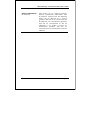
The following are the user-configurable STP parameters for the
port or port group level:
60
Variable
Description
Default
Value
Port Priority
A relative priority for each
port – lower numbers give a
higher priority and a greater
128
Switch Management and Operating Concepts
DES-3326S Layer 3 Fast Ethernet Switch User’s Guide
chance of a given port being
elected as the root port
Port Cost
A value used by STP to
evaluate
paths
–
STP
calculates path costs and
selects the path with the
minimum cost as the active
path.
19 – 100Mbps
Fast Ethernet
ports
10
1000Mbps
Gigabit
Ethernet
ports
–
Table 5-5. STP Parameters – Port Group Level
Bridge Protocol Data Units
For STP to arrive at a stable network topology, the following
information is used:
•
The unique switch identifier
•
The path cost to the root associated with each switch
port
•
The port identifier
STP communicates between switches on the network using
Bridge Protocol Data Units (BPDUs). Each BPDU contains the
following information:
•
The unique identifier of the switch that the transmitting
switch currently believes is the root switch
•
The path cost to the root from the transmitting port
•
The port identifier of the transmitting port
The switch sends BPDUs to communicate and construct the
spanning-tree topology. All switches connected to the LAN on
Switch Management and Operating Concepts
61
DES-3326S Layer 3 Fast Ethernet Switch User’s Guide
which the packet is transmitted will receive the BPDU. BPDUs
are not directly forwarded by the switch, but the receiving
switch uses the information in the frame to calculate a BPDU,
and, if the topology changes, initiates a BPDU transmission.
The communication between switches via BPDUs results in the
following:
•
One switch is elected as the root switch
•
The shortest distance to the root switch is calculated for
each switch
•
A designated switch is selected. This is the switch
closest to the root switch through which packets will be
forwarded to the root.
•
A port for each switch is selected. This is the port
providing the best path from the switch to the root
switch.
•
Ports included in the STP are selected.
Creating a Stable STP Topology
If all switches have STP enabled with default settings, the
switch with the lowest MAC address in the network will become
the root switch. By increasing the priority (lowering the priority
number) of the best switch, STP can be forced to select the best
switch as the root switch.
When STP is enabled using the default parameters, the path
between source and destination stations in a switched network
might not be ideal. For instance, connecting higher-speed links
to a port that has a higher number than the current root port
can cause a root-port change. The goal is to make the fastest
link the root port.
62
Switch Management and Operating Concepts
DES-3326S Layer 3 Fast Ethernet Switch User’s Guide
STP Port States
The BPDUs take some time to pass through a network. This
propagation delay can result in topology changes where a port
that transitioned directly from a Blocking state to a Forwarding
state could create temporary data loops. Ports must wait for
new network topology information to propagate throughout the
network before starting to forward packets. They must also
wait for the packet lifetime to expire for BPDU packets that
were forwarded based on the old topology. The forward delay
timer is used to allow the network topology to stabilize after a
topology change.
In addition, STP specifies a series of states a port must
transition through to further ensure that a stable network
topology is created after a topology change.
Each port on a switch using STP exists is in one of the
following five states:
•
Blocking – the port is blocked from forwarding or
receiving packets
•
Listening – the port is waiting to receive BPDU packets
that may tell the port to go back to the blocking state
•
Learning – the port is adding addresses to its forwarding
database, but not yet forwarding packets
•
Forwarding – the port is forwarding packets
•
Disabled – the port only responds to network
management messages and must return to the blocking
state first
A port transitions from one state to another as follows:
Switch Management and Operating Concepts
63
DES-3326S Layer 3 Fast Ethernet Switch User’s Guide
•
From initialization (switch boot) to blocking
•
From blocking to listening or to disabled
•
From listening to learning or to disabled
•
From learning to forwarding or to disabled
•
From forwarding to disabled
•
From disabled to blocking
Figure 5-2. STP Port State Transitions
64
Switch Management and Operating Concepts
DES-3326S Layer 3 Fast Ethernet Switch User’s Guide
When STP is enabled, every port on every switch in the network
goes through the blocking state and then transitions through
the states of listening and learning at power up. If properly
configured, each port stabilizes to the forwarding or blocking
state.
No packets (except BPDUs) are forwarded from, or received by,
STP enabled ports until the forwarding state is enabled for that
port.
Default Spanning-Tree Configuration
Feature
Default Value
Enable state
STP enabled for all ports
Port priority
128
Port cost
19
Bridge Priority
32,768
Table 5-7. Default STP Parameters
User-Changeable STA Parameters
The factory default setting should cover the majority of
installations. However, it is advisable to keep the default
settings as set at the factory; unless, it is absolutely necessary.
The user changeable parameters in the Switch are as follows:
•
Priority A Priority for the switch can be set from 0
to 65535. 0 is equal to the highest Priority.
•
Hello Time The Hello Time can be from 1 to 10
seconds.
This is the interval between two
Switch Management and Operating Concepts
65
DES-3326S Layer 3 Fast Ethernet Switch User’s Guide
transmissions of BPDU packets sent by the Root
Bridge to tell all other Switches that it is indeed the
Root Bridge. If you set a Hello Time for your Switch,
and it is not the Root Bridge, the set Hello Time will
be used if and when your Switch becomes the Root
Bridge.
Note: The Hello Time cannot be longer than the Max. Age.
Otherwise, a configuration error will occur.
•
Max. Age The Max. Age can be from 6 to 40 seconds.
At the end of the Max. Age, if a BPDU has still not
been received from the Root Bridge, your Switch will
start sending its own BPDU to all other Switches for
permission to become the Root Bridge. If it turns out
that your Switch has the lowest Bridge Identifier, it
will become the Root Bridge.
•
Forward Delay Timer The Forward Delay can be
from 4 to 30 seconds. This is the time any port on
the Switch spends in the listening state while moving
from the blocking state to the forwarding state.
Note: Observe the following formulas when setting the above
parameters:
Max. Age ≤ 2 x (Forward Delay - 1 second)
Max. Age ≥ 2 x (Hello Time + 1 second)
66
•
Port Priority A Port Priority can be from 0 to 255.
The lower the number, the greater the probability the
port will be chosen as the Root Port.
•
Port Cost A Port Cost can be set from 1 to 65535.
The lower the number, the greater the probability the
port will be chosen to forward packets.
Switch Management and Operating Concepts
DES-3326S Layer 3 Fast Ethernet Switch User’s Guide
Illustration of STP
A simple illustration of three Bridges (or three switches)
connected in a loop is depicted below. In this example, you can
anticipate some major network problems if the STP assistance
is not applied. If Bridge A broadcasts a packet to Bridge B,
Bridge B will broadcast it to Bridge C, and Bridge C will
broadcast it to back to Bridge A ... and so on. The broadcast
packet will be passed indefinitely in a loop, potentially causing
a network failure.
STP can be applied as shown in Figure 2-4. In this example,
STP breaks the loop by blocking the connection between Bridge
B and C. The decision to block a particular connection is based
on the STP calculation of the most current Bridge and Port
settings. Now, if Bridge A broadcasts a packet to Bridge C,
then Bridge C will drop the packet at port 2 and the broadcast
will end there.
Setting-up STP using values other than the defaults, can be
complex. Therefore, you are advised to keep the default factory
settings and STP will automatically assign root bridges/ports
and block loop connections. Influencing STP to choose a
particular switch as the root bridge using the Priority setting,
or influencing STP to choose a particular port to block using
the Port Priority and Port Cost settings is, however, relatively
straight forward.
Switch Management and Operating Concepts
67
DES-3326S Layer 3 Fast Ethernet Switch User’s Guide
Figure 5-3. Before Applying the STA Rules
In this example, only the default STP values are used.
68
Switch Management and Operating Concepts
DES-3326S Layer 3 Fast Ethernet Switch User’s Guide
Figure 5-4. After Applying the STA Rules
The switch with the lowest Bridge ID (switch C) was elected the
root bridge, and the ports were selected to give a high port cost
between switches B and C. The two (optional) Gigabit ports
(default port cost = 10) on switch A are connected to one
(optional) Gigabit port on both switch B and C. The redundant
link between switch B and C is deliberately chosen as a 100
Mbps Fast Ethernet link (default port cost = 19). Gigabit ports
could be used, but the port cost should be increased from the
default to ensure that the link between switch B and switch C
is the blocked link.
Switch Management and Operating Concepts
69
DES-3326S Layer 3 Fast Ethernet Switch User’s Guide
Link Aggregation
Link aggregation is used to combine a number of ports together
to make a single high-bandwidth data pipeline. The
participating parts are called members of a link aggregation
group, with one port designated as the master port of the
group. Since all members of the link aggregation group must be
configured to operate in the same manner, the configuration of
the master port is applied to all members of the link
aggregation group. Thus, when configuring the ports in a link
aggregation group, you only need to configure the master port.
The DES-3326S supports link aggregation groups, which may
include from 2 to 8 switch ports each, except for a Gigabit link
aggregation group which consists of the 2 (optional) Gigabit
Ethernet ports of the front panel. These ports are the two
1000BASE-SX, -LX –TX or GBIC ports contained in a frontpanel mounted module.
70
Switch Management and Operating Concepts
DES-3326S Layer 3 Fast Ethernet Switch User’s Guide
Figure 5-5. Link Aggregation Group
Data transmitted to a specific host (destination address) will
always be transmitted over the same port in a link aggregation
group. This allows packets in a data stream to arrive in the
same order they were sent. A aggregated link connection can be
made with any other switch that maintains host-to-host data
streams over a single link aggregate port. Switches that use a
load-balancing scheme that sends the packets of a host-to-host
data stream over multiple link aggregation ports cannot have a
aggregated connection with the DES-3326S switch.
Switch Management and Operating Concepts
71
DES-3326S Layer 3 Fast Ethernet Switch User’s Guide
VLANs
A VLAN is a collection of end nodes grouped by logic rather
than physical location.
End nodes that frequently
communicate with each other are assigned to the same VLAN,
regardless of where they are located physically on the network.
Logically, a VLAN can be equated to a broadcast domain,
because broadcast packets are forwarded only to members of
the VLAN on which the broadcast was initiated.
Notes About VLANs on the DES-3326S
1. The DES-3326S supports IEEE 802.1Q VLANs.
The port untagging function can be used to
remove the 802.1Q tag from packet headers to
maintain compatibility with devices that are tagunaware (that is, network devices that do not
support IEEE 802.1Q VLANs or tagging).
2. The switch’s default - in both Layer 2 Only
mode and IP Routing mode - is to assign all
ports to a single 802.1Q VLAN named
DEFAULT_VLAN.
3. The switch allows the assignment of an IP
interface to each VLAN, in IP Routing mode.
The VLANs must be configured before setting up
the IP interfaces
4. A VLAN that is not assigned an IP interface will
behave as a layer 2 VLAN – and IP routing, by
the switch, will not be possible to this VLAN
regardless of the switch’s operating mode.
72
Switch Management and Operating Concepts
DES-3326S Layer 3 Fast Ethernet Switch User’s Guide
IEEE 802.1Q VLANs
Some relevant terms:
Tagging - The act of putting 802.1Q VLAN information into the
header of a packet.
Untagging - The act of stripping 802.1Q VLAN information out
of the packet header.
Ingress port - A port on a switch where packets are flowing
into the switch and VLAN decisions must be made.
Egress port - A port on a switch where packets are flowing out
of the switch, either to another switch or to an end station, and
tagging decisions must be made.
IEEE 802.1Q (tagged) VLANs are implemented on the DES3326S Layer 3 switch. 802.1Q VLANs require tagging, which
enables the VLANs to span an entire network (assuming all
switches on the network are IEEE 802.1Q-compliant).
Any port can be configured as either tagging or untagging. The
untagging feature of IEEE 802.1Q VLANs allow VLANs to work
with legacy switches that don’t recognize VLAN tags in packet
headers. The tagging feature allows VLANs to span multiple
802.1Q-compliant switches through a single physical
connection and allows Spanning Tree to be enabled on all ports
and work normally.
802.1Q VLAN Packet Forwarding
Packet forwarding decisions are made based upon the following
three types of rules:
•
Ingress rules – rules relevant to the classification of
received frames belonging to a VLAN.
Switch Management and Operating Concepts
73
DES-3326S Layer 3 Fast Ethernet Switch User’s Guide
•
Forwarding rules between ports – decides filter or
forward the packet
•
Egress rules – determines if the packet must be sent
tagged or untagged.
Figure 5-6. IEEE 802.1Q Packet Forwarding
802.1Q VLAN Tags
The figure below shows the 802.1Q VLAN tag. There are four
additional octets inserted after the source MAC address. Their
presence is indicated by a value of 0x8100 in the EtherType
field. When a packet’s EtherType field is equal to 0x8100, the
packet carries the IEEE 802.1Q/802.1p tag.
The tag is
contained in the following two octets and consists of 3 bits or
user priority, 1 bit of Canonical Format Identifier (CFI – used
for encapsulating Token Ring packets so they can be carried
74
Switch Management and Operating Concepts
DES-3326S Layer 3 Fast Ethernet Switch User’s Guide
across Ethernet backbones) and 12 bits of VLAN ID (VID). The
3 bits of user priority are used by 802.1p. The VID is the VLAN
identifier and is used by the 802.1Q standard. Because the
VID is 12 bits long, 4094 unique VLANs can be identified.
The tag is inserted into the packet header making the entire
packet longer by 4 octets. All of the information contained in
the packet originally is retained.
Figure 5-7. IEEE 802.1Q Tag
The EtherType and VLAN ID are inserted after the MAC source
address, but before the original EtherType/Length or Logical
Link Control. Because the packet is now a bit longer than it
was originally, the Cyclic Redundancy Check (CRC) must be
recalculated.
Switch Management and Operating Concepts
75
DES-3326S Layer 3 Fast Ethernet Switch User’s Guide
Figure 5-8. Adding an IEEE 802.1Q Tag
Port VLAN ID
Packets that are tagged (are carrying the 802.1Q VID
information) can be transmitted from one 802.1Q compliant
network device to another with the VLAN information intact.
This allows 802.1Q VLANs to span network devices (and indeed,
the entire network – if all network devices are 802.1Q
compliant).
Unfortunately, not all network devices are 802.1Q compliant.
These devices are referred to as tag-unaware. 802.1Q devices
are referred to as tag-aware.
Prior to the adoption 802.1Q VLANs, port-based and MACbased VLANs were in common use. These VLANs relied upon a
Port VLAN ID (PVID) to forward packets. A packet received on
a given port would be assigned that port’s PVID and then be
forwarded to the port that corresponded to the packet’s
destination address (found in the switch’s forwarding table). If
the PVID of the port that received the packet is different from
the PVID of the port that is to transmit the packet, the switch
will drop the packet.
76
Switch Management and Operating Concepts
DES-3326S Layer 3 Fast Ethernet Switch User’s Guide
Within the switch, different PVIDs mean different VLANs.
(remember that two VLANs cannot communicate without an
external router). So, VLAN identification based upon the PVIDs
cannot create VLANs that extend outside a given switch (or
switch stack).
Every physical port on a switch has a PVID. 802.1Q ports are
also assigned a PVID, for use within the switch. If no VLANs
are defined on the switch, all ports are then assigned to a
default VLAN with a PVID equal to 1. Untagged packets are
assigned the PVID of the port on which they were received.
Forwarding decisions are based upon this PVID, in so far as
VLANs are concerned. Tagged packets are forwarded according
to the VID contained within the tag. Tagged packets are also
assigned a PVID, but the PVID is not used to make packet
forwarding decisions, the VID is.
Tag-aware switches must keep a table to relate PVIDs within
the switch to VIDs on the network. The switch will compare
the VID of a packet to be transmitted to the VID of the port that
is to transmit the packet. If the two VIDs are different, the
switch will drop the packet. Because of the existence of the
PVID for untagged packets and the VID for tagged packets, tagaware and tag-unaware network devices can coexist on the
same network.
A switch port can have only one PVID, but can have as many
VIDs as the switch has memory in its VLAN table to store them.
Because some devices on a network may be tag-unaware, a
decision must be made at each port on a tag-aware device
before packets are transmitted – should the packet to be
transmitted have a tag or not? If the transmitting port is
connected to a tag-unaware device, the packet should be
untagged. If the transmitting port is connected to a tag-aware
device, the packet should be tagged.
Switch Management and Operating Concepts
77
DES-3326S Layer 3 Fast Ethernet Switch User’s Guide
Tagging and Untagging
Every port on an 802.1Q compliant switch can be configured as
tagging or untagging.
Ports with tagging enabled will put the VID number, priority
and other VLAN information into the header of all packets that
flow into and out of it. If a packet has previously been tagged,
the port will not alter the packet, thus keeping the VLAN
information intact. The VLAN information in the tag can then
be used by other 802.1Q compliant devices on the network to
make packet forwarding decisions.
Ports with untagging enabled will strip the 802.1Q tag from all
packets that flow into and out of those ports. If the packet
doesn’t have an 802.1Q VLAN tag, the port will not alter the
packet. Thus, all packets received by and forwarded by an
untagging port will have no 802.1Q VLAN information.
(Remember that the PVID is only used internally within the
switch). Untagging is used to send packets from an 802.1Qcompliant network device to a non-compliant network device.
Ingress Filtering
A port on a switch where packets are flowing into the switch
and VLAN decisions must be made is referred to as an ingress
port. If ingress filtering is enabled for a port, the switch will
examine the VLAN information in the packet header (if present)
and decide whether or not to forward the packet.
If the packet is tagged with VLAN information, the ingress port
will first determine if the ingress port itself is a member of the
tagged VLAN. If it is not, the packet will be dropped. If the
ingress port is a member of the 802.1Q VLAN, the switch then
determines if the destination port is a member of the 802.1Q
VLAN. If it is not, the packet is dropped. If the destination
port is a member of the 802.1Q VLAN, the packet is forwarded
78
Switch Management and Operating Concepts
DES-3326S Layer 3 Fast Ethernet Switch User’s Guide
and the destination port transmits it to its attached network
segment.
If the packet is not tagged with VLAN information, the ingress
port will tag the packet with its own PVID as a VID (if the port
is a tagging port).
The switch then determines if the
destination port is a member of the same VLAN (has the same
VID) as the ingress port. If it does not, the packet is dropped.
If it has the same VID, the packet is forwarded and the
destination port transmits it on its attached network segment.
This process is referred to as ingress filtering and is used to
conserve bandwidth within the switch by dropping packets that
are not on the same VLAN as the ingress port at the point of
reception.
This eliminates the subsequent processing of
packets that will just be dropped by the destination port.
VLANs in Layer 2 Only Mode
The switch initially configures one VLAN, VID = 1, called the
DEFAULT_VLAN. The factory default setting assigns all ports
on the switch to the DEFAULT_VLAN.
Packets cannot cross VLANs if the switch is in Layer 2 Only
mode. If a member of one VLAN wants to connect to another
VLAN, the link must be through an external router.
When the switch is in Layer 2 Only mode, 802.1Q VLANs are
supported.
If no VLANs are configured on the switch and the switch is in
Layer 2 Only mode, then all packets will be forwarded to any
destination port. Packets with unknown source addresses will
be flooded to all ports. Broadcast and multicast packets will
also be flooded to all ports.
Switch Management and Operating Concepts
79
DES-3326S Layer 3 Fast Ethernet Switch User’s Guide
A VLAN that does not have a corresponding IP interface defined
for it, will function as a Layer 2 Only VLAN – regardless of the
Switch Operation mode.
Layer 3-Based VLANs
Layer 3-based VLANs use network-layer addresses (subnet
address for TCP/IP) to determine VLAN membership. These
VLANs are based on layer 3 information, but this does not
constitute a ‘routing’ function.
The DES-3326S allows an IP subnet to be configured for each
802.1Q VLAN that exists on the switch.
Even though a switch inspects a packet’s IP address to
determine VLAN membership, no route calculation is
performed, the RIP protocol is not employed, and packets
traversing the switch are bridged using the Spanning Tree
algorithm.
A switch that implements layer 3 (or ‘subnet’) VLANs without
performing any routing function between these VLANs is
referred to as performing ‘IP Switching’.
IP Addressing and Subnetting
This section gives basic information needed to configure your
Layer 3 switch for IP routing. The information includes how IP
addresses are broken down and how subnetting works. You
will learn how to assign each interface on the router an IP
address with a unique subnet.
Definitions
•
80
IP Address – the unique number ID assigned to each host or
interface on a network. IP addresses have the form
xxx.xxx.xxx.xxx.
Switch Management and Operating Concepts
DES-3326S Layer 3 Fast Ethernet Switch User’s Guide
•
•
•
•
•
•
Subnet – a portion of a network sharing a particular network
address.
Subnet mask – a 32-bit number used to describe which
portion of a Network Address refers to the subnet and which
portion refers to the host. Subnet masks have the form
xxx.xxx.xxx.xxx.
Interface – a network connection
IP Interface – another name for subnet.
Network Address – the resulting 32-bit number from a
bitwise logical AND operation performed between an IP
address and a subnet mask.
Subnet Address – another name for network address.
IP Addresses
The Internet Protocol (IP) was designed for routing data
between network sites.
Later, it was adapted for routing
between networks (referred to as “subnets”) within a site. The
IP defines a way of generating a unique number that can be
assigned each network in the internet and each of the
computers on each of those networks. This number is called
the IP address.
IP addresses use a “dotted decimal” notation. Here are some
examples of IP addresses written in this format:
1.
2.
3.
210.202.204.205
189.21.241.56
125.87.0.1
This allows IP address to be written in a string of 4 decimal
(base 10) numbers. Computers can only understand binary
(base 2) numbers, and these binary numbers are usually
Switch Management and Operating Concepts
81
DES-3326S Layer 3 Fast Ethernet Switch User’s Guide
grouped together in bytes, or eight bits. (A bit is a binary
digit – either a “1” or a “0”). The dots (periods) simply make the
IP address easier to read. A computer sees an IP address not
as four decimal numbers, but as a long string of binary digits
(32 binary digits or 32 bits, IP addresses are 32-bit addresses).
The three IP addresses in the example above, written in binary
form are:
1.
2.
3.
11010010.11001010.11001100.11001101
10111101.00010101.11110001.00111000
01111101.01010111.00000000.00000001
The dots are included to make the numbers easier to read.
Eight binary bits are called a ‘byte’ or an ‘octet’. An octet can
represent any decimal value between ‘0’ (00000000) and ‘255’
(11111111). IP addresses, represented in decimal form, are
four numbers whose value is between ‘0’ to ‘255’. The total
range of IP addresses are then:
Lowest possible IP address Highest possible IP address -
0.0.0.0
255.255.255.255
To convert decimal numbers to 8-bit binary numbers (and viceversa), you can use the following chart:
Binary Octet Digit
27
26
25
24
23
22
21
Decimal Equivalent
Binary Number
128+64+32+16+8+4+2+1=
255
128
1
64
1
32
1
16
1
8
1
4
1
2
1
2
0
1
1
Table 5-8. Binary to Decimal Conversion
82
Switch Management and Operating Concepts
DES-3326S Layer 3 Fast Ethernet Switch User’s Guide
Each digit in an 8-bit binary number (an octet) represents a
power of two. The left-most digit represents 2 raised to the 7th
power (2x2x2x2x2x2x2=128) while the right-most digit
represents 2 raised to the 0th power (any number raised to the
0th power is equal to one, by definition).
IP addresses actually consist of two parts, one identifying the
network and one identifying the destination (node) within the
network.
The IP address discussed above is one part and a second
number called the Subnet mask is the other part. To make
this a bit more confusing, the subnet mask has the same
numerical form as an IP address.
Address Classes
Address classes refer to the range of numbers in the subnet
mask. Grouping the subnet masks into classes makes the task
of dividing a network into subnets a bit easier.
There are 5 address classes. The first 4 bits in the IP address
determine which class the IP address falls in.
•
•
•
•
•
Class A addresses begin with 0xxx, or 1 to 126 decimal.
Class B addresses begin with 10xx, or 128 to 191 decimal.
Class C addresses begin with 110x, or 192 to 223 decimal.
Class D addresses begin with 1110, or 224 to 239 decimal.
Class E addresses begin with 1111, or 240 to 254 decimal.
Addresses beginning with 01111111, or 127 decimal, are
reserved. They are used for internal testing on a local machine
(called loopback). The address 127.0.0.1 can always be pinged
from a local node because it forms a loopback and points back
to the same node.
Class D addresses are reserved for multicasting.
Switch Management and Operating Concepts
83
DES-3326S Layer 3 Fast Ethernet Switch User’s Guide
Class E Addresses are reserved for future use. They are not
used for node addresses.
The part of the IP address that belongs to the network is the
part that is ‘hidden’ by the ‘1’s in the subnet mask. This can
be seen below:
•
•
•
Class A
Class B
Class C
NETWORK.node.node.node
NETWORK.NETWORK.node.node
NETWORK.NETWORK.NETWORK.node
For example, the IP address 10.42.73.210 is a Class A address,
so the Network part of the address (called the Network Address)
is the first octet (10.x.x.x). The node part of the address is the
last three octets (x.42.73.210).
To specify the network address for a given IP address, the node
part is set to all “0”s. In our example, 10.0.0.0 specifies the
network address for 10.42.73.210. When the node part is set
to all “1”s, the address specifies a broadcast address. So,
10.255.255.255 is the broadcast address for the network
10.0.0.0.
Subnet Masking
A subnet mask can be applied to an IP address to identify the
network and the node parts of the address. A bitwise logical
AND operation between the IP address and the subnet mask
results in the Network Address.
For example:
00001010.00101010.01001001.11010010
Class A IP address
11111111.00000000.00000000.00000000
Class A Subnet Mask
10.42.73.210
00001010.00000000.00000000.00000000
Network Address
10.0.0.0
84
255.0.0.0
Switch Management and Operating Concepts
DES-3326S Layer 3 Fast Ethernet Switch User’s Guide
The Default subnet masks are:
•
•
•
Class A – 11111111.00000000.00000000.00000000
255.0.0.0
Class B – 11111111.11111111.00000000.00000000
255.255.0.0
Class C – 1111111.11111111.11111111.00000000
255.255.255.0
Additional bits can be added to the default subnet mask for a
given Class to further subnet a network. When a bitwise
logical AND operation is performed between the subnet mask
and the IP address, the result defines the Subnet Address.
Some restrictions apply to subnet addresses. Addresses of all
“0”s and all “1”s are reserved for the local network (when a host
does not know it’s network address) and for all hosts on the
network (the broadcast address). This also applies to subnets.
A subnet address cannot be all “0”s or all “1”s. A 1-bit subnet
mask is also not allowed.
Calculating the Number of Subnets and Nodes
To calculate the number of subnets and nodes, use the formula
(2n – 2) where n = the number of bits in either the subnet mask
or the node portion of the IP address. Multiplying the number
of subnets by the number of nodes available per subnet gives
the total number of nodes for the entire network.
Example
00001010.00101010.01001001.11010010
Class A IP address
11111111.11100000.00000000.00000000
Subnet Mask
00001010.00100000.00000000.00000000
Network Address
00001010.00101010.11111111.11111111
Broadcast Address
Switch Management and Operating Concepts
10.42.73.210
255.224.0.0
10.32.0.0
10.32.255.255
85
DES-3326S Layer 3 Fast Ethernet Switch User’s Guide
This example uses an 11-bit subnet mask. (There are 3
additional bits added to the default Class A subnet mask). So
the number of subnets is:
23 – 2 = 8 – 2 = 6
Subnets of all “0”s and all “1”s are not allowed, so 2 subnets
are subtracted from the total.
The number of bits used in the node part of the address is 24 –
3 = 21 bits, so the total number of nodes is:
221 – 2 = 2,097,152 – 2 = 2,097,150
Multiplying the number of subnets times the number of nodes
gives 12,582,900 possible nodes.
Note that this is less than the 16,777,214 possible nodes that
an unsubnetted class A network would have.
Subnetting reduces the number of possible nodes for a given
network, but increases the segmentation of the network.
Classless InterDomain Routing – CIDR
Under CIDR, the subnet mask notation is reduced to a
simplified shorthand. Instead of specifying all of the bits of the
subnet mask, it is simply listed as the number of contiguous
“1”s (bits) in the network portion of the address. Look at the
subnet mask of the above example in binary 11111111.11100000.00000000.00000000 – and you can see
that there are 11 “1”s or 11 bits used to mask the network
address from the node address. Written in CIDR notation this
becomes:
10.32.0.0/11
86
Switch Management and Operating Concepts
DES-3326S Layer 3 Fast Ethernet Switch User’s Guide
# of
Bits
Subnet Mask
# of
Subnets
# of
Hosts
Total Hosts
255.192.0.0
CID
R
Nota
tion
/10
2
2
8388604
3
255.224.0.0
/11
6
4
255.240.0.0
/12
14
5
6
7
8
9
10
11
12
13
14
15
16
17
255.248.0.0
255.252.0.0
255.254.0.0
255.255.0.0
255.255.128.0
255.255.192.0
255.255.224.0
255.255.240.0
255.255.248.0
255.255.252.0
255.255.254.0
255.255.255.0
255.255.255.1
28
255.255.255.1
92
255.255.255.2
24
255.255.255.2
40
255.255.255.2
48
255.255.255.2
52
/13
/14
/15
/16
/17
/18
/19
/20
/21
/22
/23
/24
/25
30
62
126
254
510
1022
2046
4094
8190
16382
32766
65534
131070
419430
2
209715
0
104857
4
524286
262142
131070
65534
32766
16382
8190
4094
2046
1022
510
254
126
15728580
16252804
16514820
16645636
16710660
16742404
16756740
16760836
16756740
16742404
16710660
16645636
16514820
/26
262142
62
16252804
/27
525286
30
15728580
/28
104857
4
209715
0
419430
2
14
14680036
6
12582900
2
8388604
18
19
20
21
22
/29
/30
12582900
14680036
Table 5-9. Class A Subnet Masks
# of
Bits
2
3
4
5
6
7
Subnet Mask
255.255.192
255.255.224.0
255.255.240.0
255.255.248.0
255.255.252.0
255.255.254.0
CIDR
Notation
/18
/19
/20
/21
/22
/23
# of
Subnets
2
6
14
30
62
126
Switch Management and Operating Concepts
# of
Hosts
16382
8190
4094
2046
1022
510
Total
Hosts
32764
49140
57316
61380
63364
64260
87
DES-3326S Layer 3 Fast Ethernet Switch User’s Guide
8
9
10
11
12
13
14
255.255.255.0
255.255.255.128
255.255.255.192
255.255.255.224
255.255.255.240
255.255.255.248
255.255.255.252
/24
/25
/26
/27
/28
/29
/30
254
510
1022
2046
4094
8190
16382
254
126
62
30
14
6
2
64516
64260
63364
61380
57316
49140
32764
Table 5-10. Class B Subnet Masks
# of
Bits
2
3
4
5
6
Subnet Mask
255.255.255.192
255.255.255.224
255.255.255.240
255.255.255.248
255.255.255.252
CIDR
Notation
/26
/27
/28
/29
/30
# of
Subnets
2
6
14
30
62
# of
Hosts
62
30
14
6
2
Total
Hosts
124
180
196
180
124
Table 5-11. Class C Subnet Masks
Setting up IP Interfaces
The Layer 3 switch allows ranges of IP addresses (OSI layer 3)
to be assigned to VLANs (OSI layer 2). Each VLAN must be
configured prior to setting up the corresponding IP interface.
An IP addressing scheme must then be established, and
implemented when the IP interfaces are set up on the switch.
An example is presented below:
VLAN Name
88
VID
Switch Ports
System (default)
1
5, 6, 7, 8, 21, 22, 23, 24
Engineering
2
9, 10, 11, 12
Marketing
3
13, 14, 15, 16
Finance
4
17, 18, 19, 20
Sales
5
1, 2, 3, 4
Switch Management and Operating Concepts
DES-3326S Layer 3 Fast Ethernet Switch User’s Guide
Backbone
6
25, 26
Table 5-12. VLAN Example – Assigned Ports
In this case, 6 IP interfaces are required, so a CIDR notation of
10.32.0.0/11 (or a 11-bit) addressing scheme will work. This
addressing
scheme
will
give
a
subnet
mask
of
11111111.11100000.00000000.00000000
(binary)
or
255.224.0.0 (decimal).
Using a 10.xxx.xxx.xxx IP address notation, the above example
would give 6 network addresses and 6 subnets.
Any IP address from the allowed range of IP addresses for each
subnet can be chosen as an IP address for an IP interface on
the switch.
For this example, we have chosen the next IP address above
the network address:
VLAN Name
VID
Network Address
IP Address
System (default)
1
10.32.0.0
10.32.0.1
Engineering
2
10.64.0.0
10.64.0.1
Marketing
3
10.96.0.0
10.96.0.1
Finance
4
10.128.0.0
10.128.0.1
Sales
5
10.160.0.0
10.160.0.1
Backbone
6
10.192.0.0
10.192.0.1
Table 5-13. VLAN Example – Assigned IP Addresses
Switch Management and Operating Concepts
89
DES-3326S Layer 3 Fast Ethernet Switch User’s Guide
The 6 IP interfaces, each with an IP address (listed in the table
above), and a subnet mask of 255.224.0.0 can be entered into
the Setup IP Interface menu.
Layer 3-Based VLANs
Layer 3-based VLANs use network-layer addresses (subnet
address for TCP/IP) to determine VLAN membership. These
VLANs are based on layer 3 information, but this does not
constitute a ‘routing’ function.
The DES-3326S allows an IP subnet to be configured for each
802.1Q VLAN that exists on the switch.
Even though a switch inspects a packet’s IP address to
determine VLAN membership, no route calculation is
performed, the RIP protocol is not employed, and packets
traversing the switch are bridged using the Spanning Tree
algorithm.
A switch that implements layer 3 (or ‘subnet’) VLANs without
performing any routing function between these VLANs is
referred to as performing ‘IP Switching’.
Internet Protocols
This is a brief introduction to the suite of Internet Protocols
frequently referred to as TCP/IP. It is intended to give the
reader a reasonable understanding of the available facilities
and some familiarity with terminology. It is not intended to be
a complete description.
90
Switch Management and Operating Concepts
DES-3326S Layer 3 Fast Ethernet Switch User’s Guide
Protocol Layering
The Internet Protocol (IP) divides the tasks necessary to route
and forward packets across networks by using a layered
approach. Each layer has clearly defined tasks, protocol, and
interfaces for communicating with adjacent layers, but the
exact way these tasks are accomplished is left to individual
software designers. The Open Systems Interconnect (OSI)
seven-layer model has been adopted as the reference for the
description of modern networking, including the Internet.
A diagram of the OSI model is shown below (note that this is
not a complete listing of the protocols contained within each
layer of the model):
Figure 5-8. OSI Seven Layer Network Model
Each layer is a distinct set of programs executing a distinct set
of protocols designed to accomplish some necessary tasks.
They are separated from the other layers within the same
Switch Management and Operating Concepts
91
DES-3326S Layer 3 Fast Ethernet Switch User’s Guide
system or network, but must communicate and interoperate.
This requires very well-defined and well-known methods for
transferring messages and data. This is accomplished through
the protocol stack.
Protocol layering as simply a tool for visualizing the
organization of the necessary software and hardware in a
network. In this view, Layer 2 represents switching and Layer
3 represents routing. Protocol layering is actually a set of
guidelines used in writing programs and designing hardware
that delegate network functions and allow the layers to
communicate. How these layers communicate within a stack
(for example, within a given computer) is left to the operating
system programmers.
Figure 5-9. The Protocol Stack
92
Switch Management and Operating Concepts
DES-3326S Layer 3 Fast Ethernet Switch User’s Guide
Between two protocol stacks, members of the same layer are
known as peers and communicate by well-known (open and
published) protocols. Within a protocol stack, adjacent
layers communicate by an internal interface. This interface is
usually not publicly documented and is frequently proprietary.
It has some of the same characteristics of a protocol and two
stacks from the same software vendor may communicate in the
same way. Two stacks from different software vendors (or
different products from the same vendor) may communicate in
completely different ways. As long as peers can communicate
and interoperate, this has no impact on the functioning of the
network.
The communication between layers within a given protocol
stack can be both different from a second stack and proprietary,
but communication between peers on the same OSI layer is
open and consistent.
A brief description of the most commonly used functional
layers is helpful to understand the scope of how protocol
layering works.
Layer 1
This is referred to as the physical layer. It handles the
electrical connections and signaling required to make a
physical link from one point in the network to another. It is on
this layer that the unique Media Access Control (MAC) address
is defined.
Layer 2
This layer, commonly called the switching layer, allows end
station addressing and the establishment of connections
between them.
Switch Management and Operating Concepts
93
DES-3326S Layer 3 Fast Ethernet Switch User’s Guide
Layer 2 switching forwards packets based on the unique MAC
address of each end station and offers high-performance,
dedicated-bandwidth of Fast or Gigibit Ethernet within the
network.
Layer 2 does not ordinarily extend beyond the intranet. To
connect to the Internet usually requires a router and a modem
or other device to connect to an Internet Service Provider’s
WAN. These are Layer 3 functions.
Layer 3
Commonly referred to as the routing layer, this layer provides
logical partitioning of networks (subnetting), scalability,
security, and Quality of Service (QoS).
The backbone of the Internet is built using Layer 3 functions.
IP is the premier Layer 3 protocol.
IP is itself, only one protocol in the IP protocol suite. More
extensive capabilities are found in the other protocols of the IP
suite. For example; the Domain Name System (DNS) associates
IP addresses with text names, the Dynamic Host Configuration
Protocol (DCHP) eases the administration of IP addresses, and
routing protocols such as the Routing Information Protocol
(RIP), the Open Shortest Path First (OSPF), and the Border
Gateway Protocol (BGP) enable Layer 3 devices to direct data
traffic to the intended destination. IP security allows for
authentication and encryption. IP not only allows for user-touser communication, but also for transmission from point-tomultipoint (known as IP multicasting).
Layer 4
This layer, known as the transport layer, establishes the
communication path between user applications and the
network infrastructure and defines the method of
94
Switch Management and Operating Concepts
DES-3326S Layer 3 Fast Ethernet Switch User’s Guide
communicating. TCP and UDP are well-known protocols in the
transport layer. TCP is a “connection-oriented” protocol, and
requires the establishment of parameters for transmission prior
to the exchange of data. Web technology is based on TCP.
UDP is “connectionless” and requires no connection setup.
This is important for multicast traffic, which cannot tolerate the
overhead and latency of TCP. TCP and UDP also differ in the
amount of error recovery provided and whether or not it is
visible to the user application. Both TCP and UDP are layered
on IP, which has minimal error recovery and detection. TCP
forces retransmission of data that was lost by the lower layers,
UDP does not.
Layer 7
This layer, known as the application layer, provides access to
either the end user application software such as a database.
Users communicate with the application, which in turn delivers
data to the transport layer.
Applications do not usually
communicate directly with lower layers They are written to use
a specific communication library, like the popular WinSock
library.
Software developers must decide what type of transport
mechanism is necessary. For example, Web access requires
reliable, error-free access and would demand TCP, Multimedia,
on the other hand, requires low overhead and latency and
commonly uses UDP.
TCP/IP
The TCP/IP protocol suite is a set of protocols that allow
computers to share resources across a network. TCP and IP
are only two of the Internet suite of protocols, but they are the
best known and it has become common to refer the entire
family of Internet protocols as TCP/IP.
Switch Management and Operating Concepts
95
DES-3326S Layer 3 Fast Ethernet Switch User’s Guide
TCP/IP is a layered set of protocols. An example, such as
sending e-mail, can illustrate this. There is first a protocol for
sending and receiving e-mail. This protocol defines a set of
commands to identify the sender, the recipient, and the content
of the e-mail. The e-mail protocol will not handle the actual
communication between the two computers, this is done by
TCP/IP. TCP/IP handles the actual sending and receiving of
the packets that make up the e-mail exchange.
TCP makes sure the e-mail commands and messages are
received by the appropriate computers. It keeps track of what
is sent and what is received, and retransmits any packets that
are lost or dropped. TCP also handles the division of large
messages into several Ethernet packets, and makes sure these
packets are received and reassembled in the correct order.
Because these functions are required by a large number of
applications, they are grouped into a single protocol, rather
than being the part of the specifications for just sending e-mail.
TCP is then a library of routines that application software can
use when reliable network communications are required.
IP is also a library of routines, but with a more general set of
functions. IP handles the routing of packets from the source to
the destination. This may require the packets to traverse many
different networks. IP can route packets through the necessary
gateways and provides the functions required for any user on
one network to communicate with any user on another
connected network.
The communication interface between TCP and IP is relatively
simple. When IP received a packet, it does not know how this
packet is related to others it has sent (or received) or even
which connection the packet is part of. IP only knows the
address of the source and the destination of the packet, and it
makes its best effort to deliver the packet to its destination.
96
Switch Management and Operating Concepts
DES-3326S Layer 3 Fast Ethernet Switch User’s Guide
The information required for IP to do its job is contained in a
series of octets added to the beginning of the packet called
headers. A header contains a few octets of data added to the
packet by the protocol in order to keep track of it.
Other protocols on other network devices can add and extract
their own headers to and from packets as they cross networks.
This is analogous to putting data into an envelope and sending
the envelope to a higher-level protocol, and having the higherlevel protocol put the entire envelope into it’s own, larger
envelope. This process is referred to as encapsulation.
Many levels of encapsulation are required for a packet to cross
the Internet.
Packet Headers
TCP
Most data transmissions are much longer that a single packet.
The data must then be divided up among a series of packets.
These packets must be transmitted, received and then
reassembled into the original data.
TCP handles these
functions.
TCP must know how large a packet the network can process.
To do this, the TCP protocols at each end of a connection state
how large a packet they can handle and the smaller of the two
is selected.
The TCP header contains at least 20 octets. The source and
destination TCP port numbers are the most important fields.
These specify the connection between two TCP protocols on two
network devices.
Switch Management and Operating Concepts
97
DES-3326S Layer 3 Fast Ethernet Switch User’s Guide
The header also contains a sequence number that is used to
ensure the packets are received in the correct order. The
packets are not numbered, but rather the octets the packets
contain are. If there are 100 octets of data in each packet, the
first packet is numbered 0, the second 100, the third 200, etc.
To insure that the data in a packet is received uncorrupted,
TCP adds the binary value of all the octets in the packet and
writes the sum in the checksum field. The receiving TCP
recalculates the checksum and if the numbers are different, the
packet is dropped.
Figure 5-10. TCP Packet Header
When packets have been successfully received, TCP sends an
acknowledgement.
This is simply a packet that has the
acknowledgement number field filled in.
An acknowledgement number of 1000 indicates that all of the
data up to octet 1000 has been received. If the transmitting
TCP does not receive an acknowledgement in a reasonable
amount of time, the data is resent.
98
Switch Management and Operating Concepts
DES-3326S Layer 3 Fast Ethernet Switch User’s Guide
The window field controls the amount of data being sent at any
one time. It would require too much time and overhead to
acknowledge each packet received. Each end of the TCP
connection declares how much data it is able to receive at any
one time by writing this number of octets in the window field.
The transmitting TCP decrements the number in the window
field and when it reaches zero, the transmitting TCP stops
sending data. When the receiving TCP can accept more data, it
increases the number in the window field. In practice, a single
packet can acknowledge the receipt of data and give permission
for more data to be sent.
IP
TCP sends its packets to IP with the source and destination IP
addresses. IP is only concerned with these IP addresses. It is
not concerned with the contents of the packet or the TCP
header.
IP finds a route for the packet to get to the other end of the TCP
connection.
IP adds its own header to the packet to
accomplish this.
The IP header contains the source and destination addresses,
the protocol number, and another checksum.
The protocol number tells the receiving IP which protocol to
give the packet to. Although most IP traffic uses TCP, other
protocols can be used (such as UDP).
The checksum is used by the receiving IP in the same way as
the TCP checksum.
Switch Management and Operating Concepts
99
DES-3326S Layer 3 Fast Ethernet Switch User’s Guide
Figure 5-11. IP Packet Header
The flags and fragment offset are used to keep track of packets
that must be divided among several smaller packets to cross
networks for which they are too large.
The Time-to-Live (TTL) is the number of gateways the packet is
allowed to cross between the source and destination. This
number is decremented by one when the packet crosses a
gateway and when the TTL reaches zero, the packet is dropped.
This helps reduce network traffic if a loop develops.
Ethernet
Every active Ethernet device has its own Ethernet address
(commonly called the MAC address) assigned to it by the
manufacturer. Ethernet uses 48 bit addresses.
The Ethernet header is 14 octets that include the source and
destination MAC address and a type code.
100
Switch Management and Operating Concepts
DES-3326S Layer 3 Fast Ethernet Switch User’s Guide
There is no relationship between the MAC address of a network
node and its IP address. There must be a database of Ethernet
addresses and their corresponding IP addresses.
Different protocol families can be in use on the same network.
The type code field allows each protocol family to have its own
entry.
A checksum is calculated and when the packet is received, the
checksum is recalculated. If the two checksums are different,
the packet is dropped.
Figure 5-12. Ethernet Packet Header
When a packet is received, the headers are removed. The
Ethernet Network Interface Card (NIC) removes the Ethernet
header and checks the checksum. It then looks at the type
code. If the type code is for IP, the packet is given to IP. IP
then removes the IP header and looks at its protocol field. If
the protocol field is TCP, the packet is sent to TCP. TCP then
looks at the sequence number and uses this number and other
data from the headers to reassemble the data into the original
file.
Switch Management and Operating Concepts
101
DES-3326S Layer 3 Fast Ethernet Switch User’s Guide
TCP and UDP Well-Known Ports
Application protocols run ‘on top of’ TCP/IP.
When an
application wants to send data or a message, it gives the data
to TCP. Because TCP and IP take care of the networking
details, the application can look at the network connection as a
simple data stream.
To transfer a file across a network using the File Transfer
Protocol (FTP), a connection must first be established. The
computer requesting the file transfer must connect specifically
to the FTP server on the computer that has the file.
This is accomplished using sockets. A socket is a pair of TCP
port numbers used to establish a connection from one
computer to another. TCP uses these port numbers to keep
track of connections. Specific port numbers are assigned to
applications that wait for requests. These port numbers are
referred to as ‘well-known’ ports.
TCP will open a connection to the FTP server using some
random port number, 1234 for example, on the local computer.
TCP will specify port 21 for the FTP server. Port 21 is the wellknown port number for FTP servers. Note that there are two
different FTP programs running in this example – an FTP client
that requests the file to be transferred, and an FTP server that
sends the file to the FTP client. The FTP server accepts
commands from the client, so the FTP client must know how to
connect to the server (must know the TCP port number) in
order to send commands. The FTP Server can use any TCP
port number to send the file, so long as it is sent as part of the
connection setup.
A TCP connection is then described by a set of four numbers –
the IP address and TCP port number for the local computer,
and the IP address and TCP port number for the remote
computer. The IP address is in the IP header and the TCP port
number is in the TCP header.
102
Switch Management and Operating Concepts
DES-3326S Layer 3 Fast Ethernet Switch User’s Guide
No two TCP connection can have the same set of numbers, but
only one number needs to be different. It is possible, for
example, for two users to send files to the same destination at
the same time. This could give the following connection
numbers:
Internet addresses
TCP ports
Connection 1 10.42.73.23, 10.128.12.1
1234, 21
Connection 2 10.42.73.23, 10.128.12.1
1235, 21
The same computers are making the connections, so the IP
addresses are the same. Both computers are using the same
well-known TCP port for the FTP server. The local FTP clients
are using different TCP port numbers.
FTP transfers actually involve two different connections. The
connection begins by the FTP sending commands to send a
particular file.
Once the commands are sent, a second
connection is opened for the actual data transfer. Although it
is possible to send data on the same connection, it is very
convenient for the FTP client to be able to continue to send
commands (such as ‘stop sending this file’).
UDP and ICMP
There are many applications that do not require long messages
that cannot fit into a single packet. Looking up computer
names is an example. Users wanting to make connections to
other computers will usually use a name rather than the
computer’s IP or MAC address. The user’s computer must be
able to determine the remote computer’s address before a
connection can be made. A designated computer on the
network will contain a database of computer names and their
corresponding IP and MAC addresses. The user’s computer
will send a query to the name database computer, and the
database computer will send a response. Both the query and
Switch Management and Operating Concepts
103
DES-3326S Layer 3 Fast Ethernet Switch User’s Guide
the response are very short. There is no need to divide the
query or response between multiple packets, so the complexity
of TCP is not required. If there is no response to the query
after a period of time, the query can simply be resent.
The User Datagram Protocol (UDP) is designed for
communications that do not require division among multiple
packets and subsequent reassembly. UDP does not keep track
of what is sent.
UDP uses port numbers in a way that is directly analogous to
TCP. There are well-known UDP port numbers for servers that
use UDP.
Figure 5-13. Ethernet Packet Header
The UDP header is shorter than a TCP header. UDP also uses
a checksum to verify that data is received uncorrupted.
The Internet Control Message Protocol (ICMP) is also a
simplified protocol used for error messages and messages used
by TCP/IP. ICMP, like UDP, processes messages that will fit
into a single packet. ICMP does not, however use ports
because its messages are processed by the network software.
104
Switch Management and Operating Concepts
DES-3326S Layer 3 Fast Ethernet Switch User’s Guide
The Domain Name System
Computer users usually prefer to use text names for computers
they may want to open a connection with.
Computers
themselves, require 32 bit IP addresses.
Somewhere, a
database of network devices’ text names and their
corresponding IP addresses must be maintained.
The Domain Name System (DNS) is used to map names to IP
addresses throughout the Internet and has been adapted for
use within intranets.
For two DNS servers to communicate across different subnets,
the DNS Relay of the DES-3326S must be used. The DNS
servers are identified by IP addresses.
Mapping Domain Names to Addresses
Name-to-address translation is performed by a program called
a Name server. The client program is called a Name resolver.
A Name resolver may need to contact several Name servers to
translate a name to an address.
The Domain Name System (DNS) servers are organized in a
somewhat hierarchical fashion. A single server often holds
names for a single network, which is connected to a root DNS
server – usually maintained by an ISP.
Domain Name Resolution
The domain name system can be used by contacting the name
servers one at a time, or by asking the domain name system to
do the complete name translation. The client makes a query
containing the name, the type of answer required, and a code
specifying whether the domain name system should do the
Switch Management and Operating Concepts
105
DES-3326S Layer 3 Fast Ethernet Switch User’s Guide
entire name translation, or simply return the address of the
next DNS server if the server receiving the query cannot resolve
the name.
When a DNS server receives a query, it checks to see if the
name is in its subdomain. If it is, the server translates the
name and appends the answer to the query, and sends it back
to the client. If the DNS server cannot translate the name, it
determines what type of name resolution the client requested.
A complete translation is called recursive resolution and
requires the server to contact other DNS servers until the name
is resolved. Iterative resolution specifies that if the DNS server
cannot supply an answer, it returns the address of the next
DNS server the client should contact.
Each client must be able to contact at least one DNS server,
and each DNS server must be able to contact at least one root
server.
The address of the machine that supplies domain name service
is often supplied by a DCHP or BOOTP server, or can be
entered manually and configured into the operating system at
startup.
DHCP Servers
The Dynamic Host Configuration Protocol (DHCP) is used to
dynamically assign a TCP/IP network configuration to network
devices and computers on the network. It also ensures that IP
address conflicts do not occur.
IP addresses are assigned from a pool of free addresses. Each
IP address assigned has a ‘lease’ and a ‘lease expiration period’.
The lease must be periodically renewed. If the lease is expires,
the IP address is returned to the pool of available IP addresses.
106
Switch Management and Operating Concepts
DES-3326S Layer 3 Fast Ethernet Switch User’s Guide
Usually, it is a network policy to assign the same IP address to
a given network device or computer each time.
If the IP address lease expires, the network device sends a
message to the DHCP server requesting a lease renewal. The
DHCP server can send an acknowledgement containing a new
lease and updated configuration information.
If an IP address lease cannot be renewed, the network device or
computer sends a request to all local DHCP servers attempting
to renew the lease.
If the DHCP returns a negative
acknowledgement, the network device must release its TCP/IP
configuration and reinitialize.
When a new TCP/IP configuration is received from a DHCP
server, the network device checks for a possible IP address
conflict by sending an Address Resolution Protocol (ARP)
request that contains its new IP address.
For two DHCP servers to communicate across different subnets,
the BOOTP/DHCP Relay of the DES-3326S must be used.
The DHCP servers are identified by IP addresses.
IP Routing
IP handles the task of determining how packets will get from
their source to their destination. This process is referred to as
routing.
For IP to work, the local system must be attached to a network.
It is safe to assume that any system on this network can send
packets to any other system, but when packets must cross
other networks to reach a destination on a remote network,
these packets must be handled by gateways (also called
routers).
Switch Management and Operating Concepts
107
DES-3326S Layer 3 Fast Ethernet Switch User’s Guide
Gateways connect a network with one or more other networks.
Gateways can be a computer with two network interfaces or a
specialized device with multiple network interfaces. The device
is designed to forward packets from one network to another.
IP routing is based on the network address of the destination IP
address. Each computer has a table of network addresses. For
each network address, a corresponding gateway is listed. This
is the gateway to use to communicate with that network. The
gateway does not have to be directly connected to the remote
network, it simply needs to be the first place to go on the way
to the remote network.
Before a local computer sends a packet, it first determines
whether the destination address is on the local network. If it is,
the packet can be sent directly to the remote device. If it is not,
the local computer looks for the network address of the
destination and the corresponding gateway address.
The
packet is then sent to the gateway leading to the remote
network. There is often only one gateway on a network.
A single gateway is usually defined as a default gateway, if that
gateway connects the local network to a backbone network or
to the Internet. This default gateway is also used whenever no
specific route is found for a packet, or when there are several
gateways on a network.
Local computers can use default gateways, but the gateways
themselves need a more complete routing table to be able to
forward packets correctly. A protocol is required for the
gateways to be able to communicate between themselves and to
keep their routing tables updated.
Packet Fragmentation and Reassembly
TCP/IP can be used with many different types of networks, but
not all network types can handle the same length packets.
108
Switch Management and Operating Concepts
DES-3326S Layer 3 Fast Ethernet Switch User’s Guide
When IP is transmitting large files, large packets are much
more efficient than small ones. It is preferable to use the
largest possible packet size, but still be able to cross networks
that require smaller packets.
To do this, IP can ‘negotiate’ packet size between the local and
remote ends of a connection. When an IP connection is first
made, the IPs at both ends of the connection state the largest
packet they can handle. The smaller of the two is selected.
When a IP connection crosses multiple networks, it is possible
that one of the intermediate networks has a smaller packet size
limit than the local or remote network. IP is not able to
determine the maximum packet size across all of the networks
that may make up the route for a connection. IP has, therefore,
a method to divide packets into multiple, smaller packets to
cross such networks. This division of large packets into
smaller packets is referred to as fragmentation.
A field in the TCP header indicates that a packet has been
fragmented, and other information aids in the reassembly of
the packets into the original data.
Gateways that connect networks of different packet size limits
split the large packets into smaller ones and forward the
smaller packets on their attached networks.
ARP
The Address Resolution Protocol (ARP) determines the MAC
address and IP address correspondence for a network device.
A local computer will maintain an ARP cache which is a table of
MAC addresses and the corresponding IP addresses. Before a
connection with another computer is made, the local computer
first checks its ARP cache to determine whether the remote
Switch Management and Operating Concepts
109
DES-3326S Layer 3 Fast Ethernet Switch User’s Guide
computer has an entry. If it does, the local computer reads the
remote computer’s MAC address and writes it into the
destination field of the packets to be sent.
If the remote computer does not have an ARP cache entry, the
local computer must send an ARP request and wait for a reply.
When the local computer receives the ARP reply packet, the
local ARP reads the IP MAC address pair, and then checks the
ARP cache for this entry. If there is an entry, it is updated with
the new information. If there is no entry, a new entry is made.
There are two possible cases when an ARP packet is received
by a local computer. First, the local computer is the target of
the request. If it is, the local ARP replies by sending its MAC IP
address pair back to the requesting system. Second, if the
local computer is not the target of the request, the packet is
dropped.
Multicasting
Multicasting is a group of protocols and tools that enable a
single source point to send packets to groups of multiple
destination points with persistent connections that last for
some amount of time. The main advantage to multicasting is a
decrease in the network load compared to broadcasting.
Multicast Groups
Class D IP addresses are assigned to a group of network
devices that comprise a multicast group. The four most
significant four bits of a Class D address are set to “1110”. The
following 28 bits is referred to as the ‘multicast group ID’.
Some of the range of Class D addresses are registered with the
110
Switch Management and Operating Concepts
DES-3326S Layer 3 Fast Ethernet Switch User’s Guide
Internet Assigned Numbers Authority (IANA) for special
purposes. For example, the block of multicast addresses
ranging from 224.0.0.1 to 224.0.0.225 is reserved for use by
routing protocols and some other low-level topology discovery
and maintenance protocols.
Figure 5-14. Class D Multicast Address
Some of the reserved IP multicast addresses are as follows:
Address
Assignment
224.0.0.0
Base Address (reserved)
224.0.0.1
All Systems on this subnet
224.0.0.2
All Routers on this subnet
224.0.0.3
Unassigned
224.0.0.4
DVMRP Routers
224.0.0.5
OSPF IGP Routers
224.0.0.6
OSPF IGP Designated Routers
224.0.0.7
ST Routers
224.0.0.8
ST Hosts
224.0.0.9
All RIP2 Routers
224.0.0.10
All IGRP Routers
Switch Management and Operating Concepts
111
DES-3326S Layer 3 Fast Ethernet Switch User’s Guide
224.0.0.11
Mobile Agents
224.0.0.12
DHCP Servers and Relay Agents
224.0.0.13
All PIM Routers
224.0.0.14
RSVP Encapsulation
224.0.0.15
All CBT Routers
224.0.0.16
Designated Sbm
224.0.0.17
All Sbms
224.0.0.18
VRRP
224.0.0.19
Unassigned
through
224.0.0.225
224.0.0.21
DVMRP on MOSPF
Table 5-13. Reserved Multicast Address Assignment
Internet Group Management Protocol (IGMP)
End users that want to receive multicast packets must be able
to inform nearby routers that they want to become a multicast
group member of the group these packets are being sent to.
The Internet Group Management Protocol (IGMP) is used by
multicast routers to maintain multicast group membership.
IGMP is also used to coordinate between multiple multicast
routers that may be present on a network by electing one of the
multicast routers as the ‘querier’. This router then keep track
of the membership of multicast groups that have active
members on the network. IGMP is used to determine whether
112
Switch Management and Operating Concepts
DES-3326S Layer 3 Fast Ethernet Switch User’s Guide
the router should forward multicast packets it receives to the
subnetworks it is attached to or not. A multicast router that
has received a multicast packet will check to determine if there
is at least one member of a multicast group that has requested
to receive multicast packets from this source. If there is one
member, the packet is forwarded. If there are no members, the
packet is dropped.
IGMP Versions 1 and 2
Users that want to receive multicast packets need to be able to
join and leave multicast groups. This is accomplished using
IGMP.
Figure 5-15. IGMP Message Format
The IGMP Type codes are shown below:
Type
0x11
0x1
1
0x1
6
0x1
7
0x1
Meaning
Membership Query (if Group Address is 0.0.0.0)
Specific Group Membership Query (if Group Address
is Present)
Membership Report (version 2)
Leave a Group (version 2)
Membership Report (version 1)
Switch Management and Operating Concepts
113
DES-3326S Layer 3 Fast Ethernet Switch User’s Guide
2
Table 5-14. IGMP Type Codes
Multicast routers use IGMP to manage multicast group
memberships:
•
An IGMP “report” is sent by a user’s computer to join a
group
•
IGMP version 1 does not have an explicit ‘leave’ message.
Group members have an expiration timer, and if this
timer expires before a query response is returned, the
member is dropped from the group.
•
IGMP version 2 introduces an explicit “leave” report.
When a user wants to leave a group, this report is sent
to the multicast router (for IGMP version 2).
•
Multicast routers send IGMP queries (to the all-hosts
group address: 224.0.0.1) periodically to see whether
any group members exist on their subnetworks. If there
is no response from a particular group, the router
assumes that there are no group members on the
network, and multicast packets are not forwarded.
The TTL field of query messages is set to 1 so that the queries
do not get forwarded to other subnetworks.
IGMP version 2 introduces a few extensions to IGMP version 1
such as, the election of a single multicast querier for each
network, explicit ‘leave’ reports, and queries that are specific to
a particular multicast group.
The router with the lowest IP address is elected as the querier.
The explicit group leave message is added to decrease latency,
and routers can ask for membership reports from a particular
multicast group ID.
114
Switch Management and Operating Concepts
DES-3326S Layer 3 Fast Ethernet Switch User’s Guide
The transition states a host will go through to join or leave a multicast
group are shown in the diagram below.
Figure 5-16. IGMP State Transitions
Multicast Routing Algorithms
An algorithm is not a program. An algorithm is a statement of
how a problem can be solved. A program is written to implement
an algorithm.
Multicast packets are delivered by constructing multicast trees
where the multicast router is the trunk, the branches are the
various subnetworks that may be present, and the leaves are
end recipients of the multicast packets. Several algorithms
have been developed to construct these trees and to prune
branches that have no active mulitcast group members
Switch Management and Operating Concepts
115
DES-3326S Layer 3 Fast Ethernet Switch User’s Guide
Flooding
The simplest algorithm for the delivery of multicast packets is
for the multicast router to forward a multicast packet to all
interfaces. This is referred to as flooding. An equally simple
refinement of flooding is to have the router check to determine
if a given multicast packet has been received before (in a
certain amount of time). If it has, then the packet does not
need to be forwarded at all and can be dropped. If the packet
is being received for the first time, it should be flooded to all
interface, except the interface on which it was received. This
will ensure that all routers on the network will receive at least
one copy of the multicast packet.
There are some obvious disadvantages to this simple algorithm.
Flooding duplicates a lot of packets and uses a lot of network
bandwidth. A multicast router must also keep a record of the
multicast packets it has received (for a period of time) to
determine if a given packet has been previously received. So
flooding uses a lot of router memory.
Multicast Spanning Trees
A multicast delivery tree that spans the entire network with a
single active link between routers (or subnetwork) is called a
multicast spanning tree. Links (or branches) are chosen such
that there is only one active path between any two routers.
When a router receives a multicast packet, it forwards the
packet on all links except the one on which it was received.
This guarantees that all routers in the network will receive a
copy of the packet. The only information the router needs to
store is whether a link is a part of the spanning tree (leads to a
router) or not.
Multicast spanning trees do not use group membership
information when deciding to forward or drop a given multicast
packet.
116
Switch Management and Operating Concepts
DES-3326S Layer 3 Fast Ethernet Switch User’s Guide
Reverse Path Broadcasting (RPB)
The Reverse Path Broadcasting (RPB) algorithm is an
enhancement of the multicast spanning tree algorithm. RPB
constructs a spanning tree for each multicast source. When
the router receives a multicast packet, it then checks to
determine if the packet was received on the shortest path back
from the router to the source. If the packet was received on the
shortest path back to the source, the packet is forwarded on all
links except the link on which the packet was received. If the
packet was not received on the shortest link back to the source,
the packet is dropped.
If a link-state routing protocol is in use, RPB on a local router
can determine if the path from the source through the local
router to an immediately neighboring router. If it is not, the
packet will be dropped at the next router and the packet
should not be forwarded.
If a distance-vector routing protocol is in use, a neighboring
router can either advertise its previous hop for the source as
part of its routing update messages. This will ‘poison-reverse’
the route (or have the local router prune the branch from the
multicast source to the neighboring router because the
neighboring router has a better route from the source to the
next router or subnetwork).
Since multicast packets are forwarded through the shortest
route between source and destination, RPB is fast. A given
router also does not need information about the entire
spanning tree, nor does it need a mechanism to stop the
forwarding of packets.
RPB does not use multicast group membership information in
its forwarding decisions.
Switch Management and Operating Concepts
117
DES-3326S Layer 3 Fast Ethernet Switch User’s Guide
Reverse Path Multicasting (RPM)
Reverse Path Multicasting (RPM) introduces an enhancement to
RPB – an explicit method to prune branches of the spanning
tree that have on active multicast group members for the
source. RPM constructs a tree that spans only subnetworks
with multicast group member and routers along the shortest
path between the source and the destinations.
When a multicast router receives a multicast packet, it is
forwarded using the RPB constructed spanning tree.
Subsequent routers in the tree that have no active path to
another router are referred to as leaf routers. If the multicast
packet if forwarded to a leaf router that has no active multicast
group members for the source, the leaf router will send a prune
message to the previous router. This will remove the leaf
router’s branch from the spanning tree, and no more multicast
packets (from that source) will be forwarded to it. Prune
messages have a TTL equal to one, so they can be sent only one
hop (one router) back toward the source. If the previous router
receives prune messages from all of its branch and leaf routers,
the previous router will then send it’s own prune message back
one router toward the multicast source, and the process will
repeat. In this way, multicast group membership information
can be used to prune the spanning tree between a given
multicast source and the corresponding multicast group.
Since the membership of any given multicast group can change
and the network topology can also change, RPM periodically
removes all of the prune information it has gathered from it’s
memory, and the entire process repeats.
This gives all
subsequent routers on the network a chance to receive
multicast packets from all multicast sources on the network. It
also gives all user’s a chance to join a given multicast group.
118
Switch Management and Operating Concepts
DES-3326S Layer 3 Fast Ethernet Switch User’s Guide
Multicast Routing Protocols
This section contains an overview of two multicast routing
protocols – Distance Vector Multicast Routing Protocol
(DVMRP), and Protocol Independent Multicast-Dense Mode
(PIM-DM). The most commonly used routing protocol (not a
multicast routing protocol), the Routing Information Protocol, is
discussed in a later section.
Distance Vector Multicast Routing Protocol (DVMRP)
The Distance Vector Multicast Routing Protocol (DVMRP) was
derived from the Routing Information Protocol (RIP) with the
introduction of multicast delivery trees constructed from
information about the ‘distance’ from the local router back
toward the multicast source. DVMRP uses an RPM algorithm
to construct its multicast delivery trees.
The first multicast packet received by a multicast router using
DVMRP is flooded to all interfaces except the one on which the
packet was received. Subsequent prune messages are used to
prune branches of the delivery tree that are either not on the
shortest path back to the multicast source, or that have no
active multicast group members. A ‘graft’ message is added
that allows a previously pruned branch of the multicast
delivery tree to be reactivated. This allows for lower latency
when a leaf router adds a new member to a multicast
membership group. Graft messages are forwarded one hop
(one router) back at a time toward a multicast source until they
reach a router that is on an active branch of the multicast
delivery tree.
If there is more than one multicast router on a network, the
one that has the shortest path back to the multicast source is
elected to forward multicast packets from that source. All
Switch Management and Operating Concepts
119
DES-3326S Layer 3 Fast Ethernet Switch User’s Guide
other routers will discard multicast packets from that source.
If two multicast routers on a network have the same distance
back to a multicast source, the router with the lowest IP
address is elected.
DVMRP also supports tunnel interfaces, where two multicast
routers are connected through a router that cannot process
multicast packets. This allows multicast packets to cross
networks with routers that are not multicast-aware.
Protocol-Independent Multicast – Dense Mode
There are two protocols in Protocol Independent Multicast (PIM),
Protocol Independent Multicast-Dense Mode (PIM-DM) which is
used when the multicast destinations are closely spaced, and
Protocol Independent Multicast-Sparse Mode (PIM-SM) which is
used when the multicast destinations are spaced further apart.
PIM-DM is most commonly implemented in an intranetwork
(LAN) where the distance between users is minimal.
Routing Protocols
Routing Information Protocol (RIP)
The Routing Information Protocol is a distance-vector routing
protocol. There are two types of network devices running RIP –
active and passive. Active devices advertise their routes to
others through RIP messages, while passive devices listen to
these messages. Both active and passive routers update their
routing tables based upon RIP messages that active routers
exchange. Only routers can run RIP in the active mode.
Every 30 seconds, a router running RIP broadcasts a routing
update containing a set of pairs of network addresses and a
120
Switch Management and Operating Concepts
DES-3326S Layer 3 Fast Ethernet Switch User’s Guide
distance (represented by the number of hops or routers
between the advertising router and the remote network). So,
the vector is the network address and the distance is measured
by the number of routers between the local router and the
remote network.
RIP measures distance by an integer count of the number of
hops from one network to another. A router is one hop from a
directly connected network, two hops from a network that can
be reached through a router, etc. The more routers between a
source and a destination, the greater the RIP distance (or hop
count).
There are a few rules to the routing table update process that
help to improve performance and stability. A router will not
replace a route with a newly learned one if the new route has
the same hop count (sometimes referred to as ‘cost’). So
learned routes are retained until a new route with a lower hop
count is learned.
When learned routes are entered into the routing table, a timer
is started. This timer is restarted every time this route is
advertised. If the route is not advertised for a period of time
(usually 180 seconds), the route is removed from the routing
table.
RIP does not have an explicit method to detect routing loops.
Many RIP implementations include an authorization
mechanism (a password) to prevent a router from learning
erroneous routes from unauthorized routers.
To maximize stability, the hop count RIP uses to measure
distance must have a low maximum value. Infinity (that is, the
network is unreachable) is defined as 16 hops. In other words,
if a network is more than 16 routers from the source, the local
router will consider the network unreachable.
Switch Management and Operating Concepts
121
DES-3326S Layer 3 Fast Ethernet Switch User’s Guide
RIP can also be slow to converge (to remove inconsistent,
unreachable or looped routes from the routing table) because
RIP messages propagate relatively slowly through a network.
Slow convergence can be solved by using split horizon update,
where a router does not propagate information about a route
back to the interface on which it was received. This reduces
the probability of forming transient routing loops.
Hold down can be used to force a router to ignore new route
updates for a period of time (usually 60 seconds) after a new
route update has been received. This allows all routers on the
network to receive the message.
A router can ‘poison reverse’ a route by adding an infinite (16)
hop count to a route’s advertisement. This is usually used in
conjunction with triggered updates, which force a router to
send an immediate broadcast when an update of an
unreachable network is received.
RIP Version 1 Message Format
There are two types of RIP messages: routing information
messages and information requests. The same format is used
by both types.
122
Switch Management and Operating Concepts
DES-3326S Layer 3 Fast Ethernet Switch User’s Guide
Figure 5-17. RIP v.1 Message Format
Switch Management and Operating Concepts
123
DES-3326S Layer 3 Fast Ethernet Switch User’s Guide
The COMMAND field specifies an operation according the
following table:
Command
Meaning
1
Request for partial or full routing information
2
Response containing network-distance pairs from
sender’s routing table
3
Turn on trace mode (obsolete)
4
Turn off trace mode (obsolete)
5
Reserved for Sun Microsystem’s internal use
9
Update Request
10
Update Response
11
Update Acknowledgement
Table 5-15. RIP Command Codes
The field VERSION contains the protocol version number (1 in
this case), and is used by the receiver to verify which version of
RIP the packet was sent from.
RIP 1 Message
RIP is not limited to TCP/IP. Its address format can support
up to 14 octets (when using IP, the remaining 10 octets must
be zeros). Other network protocol suites can be specified in the
Family of Source Network field (IP has a value of 2). This will
determine how the address field is interpreted.
RIP specifies that the IP address 0.0.0.0 denotes a default route.
124
Switch Management and Operating Concepts
DES-3326S Layer 3 Fast Ethernet Switch User’s Guide
The distances, measured in router hops are entered in the
Distance to Source Network, and Distance to Destination
Network fields.
RIP 1 Route Interpretation
RIP was designed to be used with classed address schemes,
and does not include an explicit subnet mask. An extension to
version 1 does allow routers to exchange subnetted addresses,
but only if the subnet mask used by the network is the same as
the subnet mask used by the address. This means the RIP
version 1 cannot be used to propagate classless addresses.
Routers running RIP version 1 must send different update
messages for each IP interface to which it is connected.
Interfaces that use the same subnet mask as the router’s
network can contain subnetted routes, other interfaces cannot.
The router will then advertise only a single route to the network.
RIP Version 2 Extensions
RIP version 2 includes an explicit subnet mask entry, so RIP
version 2 can be used to propagate variable length subnet
addresses or CIDR classless addresses. RIP version 2 also
adds an explicit next hop entry, which speeds convergence and
helps prevent the formation of routing loops.
RIP2 Message Format
The message format used with RIP2 is an extension of the RIP1
format:
Switch Management and Operating Concepts
125
DES-3326S Layer 3 Fast Ethernet Switch User’s Guide
Figure 5-18. RIP Message Format
RIP version 2 also adds a 16-bit route tag that is retained and
sent with router updates. It can be used to identify the origin
of the route.
Because the version number in RIP2 occupies the same octet
as in RIP1, both versions of the protocols can be used on a
given router simultaneously without interference.
Open Shortest Path First (OSPF)
The Open Shortest Path First (OSPF) routing protocol that uses
a link-state algorithm to determine routes to network
destinations. A “link” is an interface on a router and the
126
Switch Management and Operating Concepts
DES-3326S Layer 3 Fast Ethernet Switch User’s Guide
“state” is a description of that interface and its relationship to
neighboring routers. The state contains information such as
the IP address, subnet mask, type of network the interface is
attached to, other routers attached to the network, etc. The
collection of link-states are then collected in a link-state
database that is maintained by routers running OSPF.
OSPF specifies how routers will communicate to maintain their
link-state database and defines several concepts about the
topology of networks that use OSPF.
To limit the extent of link-state update traffic between routers,
OSPF defines the concept of Area. All routers within an area
share the exact same link-state database, and a change to this
database on one router triggers an update to the link-state
database of all other routers in that area. Routers that have
interfaces connected to more than one area are called Border
Routers and take the responsibility of distributing routing
information between areas.
One area is defined as Area 0 or the Backbone. This area is
central to the rest of the network in that all other areas have a
connection (through a router) to the backbone. Only routers
have connections to the backbone and OSPF is structured such
that routing information changes in other areas will be
introduced into the backbone, and then propagated to the rest
of the network.
When constructing a network to use OSPF, it is generally
advisable to begin with the backbone (area 0) and work
outward.
The Link-State Algorithm
An OSPF router uses a link-state algorithm to build a shortest
path tree to all destinations known to the router. The following
is a simplified description of the algorithm’s steps:
Switch Management and Operating Concepts
127
DES-3326S Layer 3 Fast Ethernet Switch User’s Guide
1. When OSPF is started, or when a change in the
routing information changes, the router
generates a link-state advertisement.
This
advertisement is a specially formatted packet
that contains information about all the linkstates on the router.
2. This link-state advertisement is flooded to all
router in the area. Each router that receives the
link-state
advertisement
will
store
the
advertisement and then forward a copy to other
routers.
3. When the link-state database of each router is
updated, the individual routers will calculate a
Shortest Path Tree to all destinations − with the
individual router as the root. The IP routing
table will then be made up of the destination
address, associated cost, and the address of the
next hop to reach each destination.
4. Once the link-state databases are updated,
Shortest Path Trees calculated, and the IP
routing tables written − if there are no
subsequent changes in the OSPF network (such
as a network link going down) there is very little
OSPF traffic.
The Shortest Path Algorithm
The Shortest Path to a destination is calculated using the
Dijkstra algorithm. Each router is places at the root of a tree
and then calculates the shortest path to each destination based
on the cumulative cost to reach that destination over multiple
possible routes. Each router will then have its own Shortest
Path Tree (from the perspective of its location in the network
128
Switch Management and Operating Concepts
DES-3326S Layer 3 Fast Ethernet Switch User’s Guide
area) even though every router in the area will have and use
the exact same link-state database.
The following sections describe the information used to build
the Shortest Path Tree.
OSPF Cost
Each OSPF interface has an associated cost (also called
“metric”) that is representative of the overhead required to send
packets over that interface. This cost is inversely proportional
to the bandwidth of the interface (i.e. a higher bandwidth
interface has a lower cost). There is then a higher cost (and
longer time delays) in sending packets over a 56 Kbps dial-up
connection than over a 10 Mbps Ethernet connection. The
formula used to calculate the OSPF cost is as follows:
Cost = 100,000,000 / bandwidth in bps
As an example, the cost of a 10 Mbps Ethernet line will be 10
and the cost to cross a 1.544 Mbps T1 line will be 64.
Shortest Path Tree
To build Router A’s shortest path tree for the network
diagramed below, Router A is put at the root of the tree and the
smallest cost link to each destination network is calculated.
Switch Management and Operating Concepts
129
DES-3326S Layer 3 Fast Ethernet Switch User’s Guide
Figure 5-19. Constructing a Shortest Path Tree
130
Switch Management and Operating Concepts
DES-3326S Layer 3 Fast Ethernet Switch User’s Guide
Router A
0
128.213.0.0
10
10
Router B
5
Router C
5
192.213.11.0
10
Router D
10
222.211.10.0
Figure 5-20. Constructing a Shortest Path Tree
The diagram above shows the network from the viewpoint of
Router A. Router A can reach 192.213.11.0 through Router B
with a cost of 10+5=15. Router A can reach 222.211.10.0
through Router C with a cost of 10+10=20. Router A can also
reach 222.211.10.0 through Router B and Router D with a cost
of 10+5+10=25, but the cost is higher than the route through
Router C. This higher-cost route will not be included in the
Router A’s shortest path tree. The resulting tree will look like
this:
Switch Management and Operating Concepts
131
DES-3326S Layer 3 Fast Ethernet Switch User’s Guide
Router A
0
128.213.0.0
10
Router B
5
192.213.11.0
10
Router C
10
222.211.10.0
Figure 5-21. Constructing a Shortest Path Tree - Completed
Note that this shortest path tree is only from the viewpoint of
Router A. The cost of the link from Router B to Router A, for
instance is not important to constructing Router A’s shortest
path tree, but is very important when Router B is constructing
its shortest path tree.
Note also that directly connected networks are reached at a
cost of 0, while other networks are reached at the cost
calculated in the shortest path tree.
Router A can now build its routing table using the network
addresses and costs calculated in building the above shortest
path tree.
Areas and Border Routers
OSPF link-state updates are forwarded to other routers by
flooding to all routers on the network. OSPF uses the concept
of areas to define where on the network routers that need to
132
Switch Management and Operating Concepts
DES-3326S Layer 3 Fast Ethernet Switch User’s Guide
receive particular link-state updates are located. This helps
ensure that routing updates are not flooded throughout the
entire network and to reduce the amount of bandwidth
consumed by updating the various router’s routing tables.
Areas establish boundaries beyond which link-state updates do
not need to be flooded. So the exchange of link-state updates
and the calculation of the shortest path tree are limited to the
area that the router is connected to.
Routers that have connections to more than one area are called
Border Routers (BR).
The Border Routers have the
responsibility of distributing necessary routing information and
changes between areas.
Areas are specific to the router interface. A router that has all
of its interfaces in the same area is called an Internal Router.
A router that has interfaces in multiple areas is called a Border
Router.
Routers that act as gateways to other networks
(possibly using other routing protocols) are called Autonomous
System Border Routers (ASBRs).
Link-State Packets
There are different types of link-state packets, four are
illustrated below:
•
Router Link-State Updates − these describe a
router’s links to destinations within an area.
•
Summary Link-State Updates – issued by Border
Routers and describe links to networks outside
the area but within the Autonomous System (AS).
•
Network Link-State Updates – issued by multiaccess areas that have more than one attached
router. One router is elected as the Designated
Router (DR) and this router issues the network
Switch Management and Operating Concepts
133
DES-3326S Layer 3 Fast Ethernet Switch User’s Guide
link-state updates describing every router on the
segment.
•
External Link-State Updates – issued by an
Autonomous System Border Router and
describes routes to destinations outside the AS
or a default route to the outside AS.
The format of these link-state updates are described in more
detail below.
Router link-state updates are flooded to all routers in the
current area.
These updates describe the destinations
reachable through all of the router’s interfaces.
Summary link-state updates are generated by Border Routers
to distribute routing information about other networks within
the AS.
Normally, all Summary link-state updates are
forwarded to the backbone (area 0) and are then forwarded to
all other areas in the network. Border Routers also have the
responsibility of distributing routing information from the
Autonomous System Border Router in order for routers in the
network to get and maintain routes to other Autonomous
Systems.
Network link-state updates are generated by a router elected as
the Designated Router on a multi-access segment (with more
than one attached router). These updates describe all of the
routers on the segment and their network connections.
External link-state updates carry routing information to
networks outside the Autonomous System. The Autonomous
System Border Router is responsible for generating and
distributing these updates.
134
Switch Management and Operating Concepts
DES-3326S Layer 3 Fast Ethernet Switch User’s Guide
OSPF Authentication
OSPF packets can be authenticated as coming from trusted
routers by the use of predefined passwords. The default for
routers is to use not authentication.
There are two other authentication methods − simple password
authentication (key) and Message Digest authentication (MD-5).
Simple Password Authentication
A password (or key) can be configured on a per-area basis.
Routers in the same area that participate in the routing domain
must be configured with the same key. This method is possibly
vulnerable to passive attacks where a link analyzer is used to
obtain the password.
Message Digest Authentication (MD-5)
MD-5 authentication is a cryptographic method. A key and a
key-ID are configured on each router. The router then uses an
algorithm to generate a mathematical “message digest” that is
derived from the OSPF packet, the key and the key-ID. This
message digest (a number) is then appended to the packet.
The key is not exchanged over the wire and a non-decreasing
sequence number is included to prevent replay attacks.
The Backbone and Area 0
OSPF limits the number of link-state updates required between
routers by defining areas within which a given router operates.
When more than one area is configured, one area is designated
as area 0 − also called the backbone.
The backbone is at the center of all other areas − all areas of
the network have a physical (or virtual) connection to the
Switch Management and Operating Concepts
135
DES-3326S Layer 3 Fast Ethernet Switch User’s Guide
backbone through a router. OSPF allows routing information
to be distributed by forwarding it into area 0, from which the
information can be forwarded to all other areas (and all other
routers) on the network.
In situations where an area is required, but is not possible to
provide a physical connection to the backbone, a virtual link
can be configured.
Virtual Links
Virtual links accomplish two purposes:
1. Linking an area that does not have a physical
connection to the backbone.
2. Patching the backbone in case there is a
discontinuity in area 0.
Areas Not Physically Connected to Area 0
All areas of an OSPF network should have a physical
connection to the backbone, but is some cases it is not possible
to physically connect a remote area to the backbone. In these
cases, a virtual link is configured to connect the remote area to
the backbone. A virtual path is a logical path between two
border routers that have a common area, with one border
router connected to the backbone.
Partitioning the Backbone
OSPF also allows virtual links to be configured to connect the
parts of the backbone that are discontinuous. This is the
equivalent to linking different area 0s together using a logical
path between each area 0. Virtual links can also be added for
redundancy to protect against a router failure. A virtual link is
136
Switch Management and Operating Concepts
DES-3326S Layer 3 Fast Ethernet Switch User’s Guide
configured between two border routers that both have a
connection to their respective area 0s.
Neighbors
Routers that are connected to the same area or segment
become neighbors in that area. Neighbors are elected via the
Hello protocol. IP multicast is used to send out Hello packets
to other routers on the segment. Routers become neighbors
when they see themselves listed in a Hello packet sent by
another router on the same segment. In this way, two-way
communication is guaranteed to be possible between any two
neighbor routers.
Any two routers must meet the following conditions before the
become neighbors:
•
Area ID − two routers having a common segment
− their interfaces have to belong to the same
area on that segment. Of course, the interfaces
should belong to the same subnet and have the
same subnet mask.
•
Authentication − OSPF allows for the
configuration of a password for a specific area.
Two routers on the same segment and belonging
to the same area must also have the same OSPF
password before they can become neighbors.
•
Hello and Dead Intervals − The Hello interval
specifies the length of time, in seconds, between
the hello packets that a router sends on an
OSPF interface. The dead interval is the number
of seconds that a router’s Hello packets have not
been seen before its neighbors declare the OSPF
router down.
OSPF routers exchange Hello
packets on each segment in order to
acknowledge each other’s existence on a
Switch Management and Operating Concepts
137
DES-3326S Layer 3 Fast Ethernet Switch User’s Guide
segment and to elect a Designated Router on
multi-access segments. OSPF requires these
intervals to be exactly the same between any two
neighbors. If any of these intervals are different,
these routers will not become neighbors on a
particular segment.
•
Stub Area Flag − any two routers also have to
have the same stub area flag in their Hello
packets in order to become neighbors.
Adjacencies
Adjacent routers go beyond the simple Hello exchange and
participate in the link-state database exchange process. OSPF
elects one router as the Designated Router (DR) and a second
router as the Backup Designated Router (BDR) on each multiaccess segment (the BDR is a backup in case of a DR failure).
All other routers on the segment will then contact the DR for
link-state database updates and exchanges. This limits the
bandwidth required for link-state database updates.
Designated Router Election
The election of the DR and BDR is accomplished using the
Hello protocol. The router with the highest OSPF priority on a
given multi-access segment will be com the DR for that
segment. In case of a tie, the router with the highest Router ID
wins. The default OSPF priority is 1. A priority of zero
indicates a router that can not be elected as the DR.
Building Adjacency
Two routers undergo a multi-step process in building the
adjacency relationship.
The following is a simplified
description of the steps required:
138
Switch Management and Operating Concepts
DES-3326S Layer 3 Fast Ethernet Switch User’s Guide
•
Down − No information has been received from
any router on the segment.
•
Attempt − On non-broadcast multi-access
networks (such as Frame Relay or X.25), this
state indicates that no recent information has
been received from the neighbor.
An effort
should be made to contact the neighbor by
sending Hello packets at the reduced rate set by
the Poll Interval.
•
Init − The interface has detected a Hello packet
coming from a neighbor but bi-directional
communication has not yet been established.
•
Two-way − Bi-directional communication with a
neighbor has been established. The router has
seen its address in the Hello packets coming
from a neighbor. At the end of this stage the DR
and BDR election would have been done. At the
end of the Two-way stage, routers will decide
whether to proceed in building an adjacency or
not. The decision is based on whether one of the
routers is a DR or a BDR or the link is a pointto-point or virtual link.
•
Exstart − (Exchange Start) Routers establish the
initial sequence number that is going to be used
in the information exchange packets.
The
sequence number insures that routers always
get the most recent information. One router will
become the primary and the other will become
secondary. The primary router will poll the
secondary for information.
•
Exchange − Routers will describe their entire
link-state database by sending database
description packets.
Switch Management and Operating Concepts
139
DES-3326S Layer 3 Fast Ethernet Switch User’s Guide
•
Loading − The routers are finalizing the
information exchange. Routers have link-state
request list and a link-state retransmission list.
Any information that looks incomplete or
outdated will be put on the request list. Any
update that is sent will be put on the
retransmission list until it gets acknowledged.
•
Full − The adjacency is now complete. The
neighboring routers are fully adjacent. Adjacent
routers will have the same link-state database.
Adjacencies on Point-to-Point Interfaces
OSPF Routers that are linked using point-to-point interfaces
(such as serial links) will always form adjacencies.
The
concepts of DR and BDR are unnecessary.
OSPF Packet Formats
All OSPF packet types begin with a standard 24 byte header
and there are five packet types. The header is described first,
and each packet type is described in a subsequent section.
All OSPF packets (except for Hello packets) forward link-state
advertisements. Link-State Update packets, for example, flood
advertisements throughout the OSPF routing domain.
140
•
OSPF packet header
•
Hello packet
•
Database Description packet
•
Link-State Request packet
•
The Link-State Update packet
•
Link-State Acknowledgment packet
Switch Management and Operating Concepts
DES-3326S Layer 3 Fast Ethernet Switch User’s Guide
The OSPF Packet Header
Every OSPF packet is preceded by a common 24 byte header.
This header contains the information necessary for a receiving
router to determine if the packet should be accepted for further
processing.
The format of the OSPP packet header is shown below:
OSPF Packet Header
Type
Version No.
Packet Length
Router ID
Area ID
Checksum
Au thentication Type
Authentication
Authentication
Figure 5-22. OSPF Packet Header
Field
Description
Version No.
The
OSPF
number
Type
The OSPF packet type.
The OSPF packet types
are as follows:
Switch Management and Operating Concepts
version
Type
Description
1
Hello
2
Database
141
DES-3326S Layer 3 Fast Ethernet Switch User’s Guide
Description
3
Link-State
Request
4
Link-State Update
5
Link-State
Acknowledgment
Packet Length
The length of the packet
in bytes.
This length
includes the 24 byte
header.
Router ID
The Router ID
packet’s source.
Area ID
A
32-bit
number
identifying the area that
this packet belongs to.
All OSPF packets are
associated with a single
area. Packets traversing
a virtual link are assigned
the backbone Area ID of
0.0.0.0
Checksum
A standard IP checksum
that includes all of the
packet’s contents except
for
the
64-bit
authentication field.
Authentication Type
The type of authentication
to be used for the packet.
Authentication
A 64-bit field used by the
authentication scheme
142
of
the
Switch Management and Operating Concepts
DES-3326S Layer 3 Fast Ethernet Switch User’s Guide
authentication scheme.
Table 5-16. OSPF Packet Header
The Hello Packet
Hello packets are OSPF packet type 1.
They are sent
periodically on all interfaces, including virtual links, in order to
establish and maintain neighbor relationships. In addition,
Hello Packets are multicast on those physical networks having
a multicast or broadcast capability, enabling dynamic discovery
of neighboring routers.
All routers connected to a common network must agree on
certain parameters such as the Network Mask, the Hello
Interval, and the Router Dead Interval. These parameters are
included in hello packets, so that differences can inhibit the
forming of neighbor relationships. A detailed explanation of the
receive processing for Hello packets, so that differences can
inhibit the forming of neighbor relationships.
The format of the Hello packet is shown below:
Switch Management and Operating Concepts
143
DES-3326S Layer 3 Fast Ethernet Switch User’s Guide
Hello Packet
Version No.
1
Packet Length
Router ID
Area ID
Checksum
Auth entication Type
Authentication
Authentication
Network Mask
Hello Interval
Optio ns
Router Priority
Router Dead Interval
Designated Router
Backup Designated Router
Neighbor
Figure 5-23. Hello Packet
Field
Description
Network Mask
The
network
associated
with
interface.
Options
The optional capabilities
supported by the router.
Hello Interval
The number of seconds
between
this
router’s
Hello packets.
Router Priority
This
router’s
Priority
The
144
mask
this
Router
Router
Switch Management and Operating Concepts
DES-3326S Layer 3 Fast Ethernet Switch User’s Guide
Priority.
The Router
Priority is used in the
election of the DR and
BDR. If this field is set to
0, the router is ineligible
become the DR or the
BDR.
Router Dead Interval
The number of seconds
that must pass before
declaring a silent router
as down.
Designated Router
The identity of the DR for
this network, in the view
of the advertising router.
The DR is identified here
by its IP interface address
on the network.
Backup Designated Router
The
identity
of
the
Backup
Designated
Router (BDR) for this
network.
The BDR is
identified here by its IP
interface address on the
network. This field is set
to 0.0.0.0 if there is no
BDR.
Neighbor
The Router Ids of each
router from whom valid
Hello packets have been
seen within the Router
Dead Interval on the
network.
Table 5-17. Hello Packet
Switch Management and Operating Concepts
145
DES-3326S Layer 3 Fast Ethernet Switch User’s Guide
The Database Description Packet
Database Description packets are OSPF packet type 2. These
packets are exchanged when an adjacency is being initialized.
They describe the contents of the topological database.
Multiple packets may be used to describe the database. For
this purpose a poll-response procedure is used. One of the
routers is designated to be master, the other a slave. The
master seconds Database Description packets (polls) which are
acknowledged by Database Description packets sent by the
slave (responses). The responses are linked to the polls via the
packets’ DD sequence numbers.
Database Description Packet
2
Version No.
Packet Length
Router ID
Area ID
Checksum
Au thentication Type
Authentication
Authentication
Reserved
I M MS
Reserved
Options
DD Sequence No.
Link-State Advertisement Header ...
Figure 5-24. Database Description Packet
Field
Options
146
Description
The optional capabilities
supported by the router.
Switch Management and Operating Concepts
DES-3326S Layer 3 Fast Ethernet Switch User’s Guide
I – bit
The Initial bit. When set
to 1, this packet is the
first in the sequence of
Database
Description
packets.
M – bit
The More bit. When set
to 1, this indicates that
more
Database
Description packets will
follow.
MS – bit
The Master Slave bit.
When set to 1, this
indicates that the router
is the master during the
Database
Exchange
process. A zero indicates
the opposite.
DD Sequence Number
User to sequence the
collection of Database
Description Packets. The
initial value (indicated by
the Initial bit being set)
should be unique. The
DD sequence number
then increments until the
complete
database
description
has
been
sent.
Table 5-18. Database Description Packet
The rest of the packet consists of a list of the topological
database’s pieces.
Each link state advertisement in the
database is described by its link state advertisement header.
Switch Management and Operating Concepts
147
DES-3326S Layer 3 Fast Ethernet Switch User’s Guide
The Link-State Request Packet
Link-State Request packets are OSPF packet type 3. After
exchanging Database Description packets with a neighboring
router, a router may find that parts of its topological database
are out of date. The Link-State Request packet is used to
request the pieces of the neighbor’s database that are more up
to date. Multiple Link-State Request packets may need to be
used. The sending of Link-State Request packets is the last
step in bringing up an adjacency.
A router that sends a Link-State Request packet has in mind
the precise instance of the database pieces it is requesting,
defined by LS sequence number, LS checksum, and LS age,
although these fields are not specified in the Link-State
Request packet itself. The router may receive even more recent
instances in response.
The format of the Link-State Request packet is shown below:
Link-State Request Packet
3
Version No.
Packet Length
Router ID
Area ID
Checksum
Au thentication Type
Authentication
Authentication
Link-State Type
Link-State ID
Advertising Router
148
Switch Management and Operating Concepts
DES-3326S Layer 3 Fast Ethernet Switch User’s Guide
Figure 5-25. Link-State Request Packet
Each advertisement requested is specified by its Link-State
Type, Link-State ID, and Advertising Router. This uniquely
identifies the advertisement, but not its instance. Link-State
Request packets are understood to be requests for the most
recent instance.
The Link-State Update Packet
Link-State Update packets are OSPF packet type 4. These
packets implement the flooding of link-state advertisements.
Each Link-State Update packet carries a collection of link-state
advertisements one hop further from its origin. Several linkstate advertisements may be included in a single packet.
Link-State Update packets are multicast on those physical
networks that support multicast/broadcast. In order to make
the flooding procedure reliable, flooded advertisements are
acknowledged in Link-State Acknowledgment packets.
If
retransmission of certain advertisements is necessary, the
retransmitted advertisements are always carried by unicast
Link-State Update packets.
The format of the Link-State Update packet is shown below:
Switch Management and Operating Concepts
149
DES-3326S Layer 3 Fast Ethernet Switch User’s Guide
Link-State Update Packet
4
Version No.
Packet Length
Router ID
Area ID
Checksum
Au thentication Type
Authentication
Authentication
Number of Advertisements
Link-State Advertisements ...
Figure 5-26. Link-State Update Packet
The body of the Link-State Update packet consists of a list of
link-state advertisements. Each advertisement begins with a
common 20-byte header, the link-state advertisement header.
Otherwise, the format of each of the five types of link-state
advertisements is different.
The Link-State Acknowledgment Packet
Link-State Acknowledgment packets are OSPF packet type 5.
To make the folding of link-state advertisements reliable,
flooded advertisements are explicitly acknowledged.
This
acknowledgment is accomplished through the sending and
receiving of Link-State Acknowledgment packets. Multiple
link-state advertisements can be acknowledged in a single
Link-State Acknowledgment packet.
Depending on the state of the sending interface and the source
of the advertisements being acknowledged, a Link-State
Acknowledgment packet is sent either to the multicast address
150
Switch Management and Operating Concepts
DES-3326S Layer 3 Fast Ethernet Switch User’s Guide
AllSPFRouters, to the multicast address AllDRouters, or as a
unicast packet.
The format of this packet is similar to that of the Data
Description packet. The body of both packets is simply a list of
link-state advertisement headers.
The format of the Link-State Acknowledgment packet is shown
below:
Link-State Acknowledgment Packet
Version No.
Packet Length
5
Router ID
Area ID
Checksum
Au thentication Type
Authentication
Authentication
Link-State Advertisement Header ...
Figure 5-27. Link-State Acknowledgement Packet
Each acknowledged link-state advertisement is described by its
link-state advertisement header. It contains all the information
required to uniquely identify both the advertisement and the
advertisement’s current instance.
Link-State Advertisement Formats
There are five distinct types of link-state advertisements. Each
link-state advertisement begins with a standard 20-byte linkstate advertisement header. Succeeding sections then diagram
the separate link-state advertisement types.
Switch Management and Operating Concepts
151
DES-3326S Layer 3 Fast Ethernet Switch User’s Guide
Each link-state advertisement describes a piece of the OSPF
routing domain.
Every router originates a router links
advertisement. In addition, whenever the router is elected as
the Designated Router, it originates a network links
advertisement. Other types of link-state advertisements may
also be originated. The flooding algorithm is reliable, ensuring
that all routers have the same collection of link-state
advertisements. The collection of advertisements is called the
link-state (or topological) database.
From the link-state database, each router constructs a shortest
path tree with itself as root. This yields a routing table.
There are four types of link state advertisements, each using a
common link state header. These are:
•
Router Links Advertisements
•
Network Links Advertisements
•
Summary Link Advertisements
•
Autonomous System Link Advertisements
The Link State Advertisement Header
All link state advertisements begin with a common 20-byte
header. This header contains enough information to uniquely
identify the advertisements (Link State Type, Link State ID, and
Advertising Router).
Multiple instances of the link state
advertisement may exist in the routing domain at the same
time. It is then necessary to determine which instance is more
recent. This is accomplished by examining the link state age,
link state sequence number and link state checksum fields that
are also contained in the link state advertisement header.
The format of the Link State Advertisement Header is shown
below:
152
Switch Management and Operating Concepts
DES-3326S Layer 3 Fast Ethernet Switch User’s Guide
Link-State Advertisement Header
Link-State Age
Optio ns
Link-State Type
Link-State ID
Advertising Router
Link-State Sequence Numb er
Link-State Checksum
Length
Figure 5-28. Link-State Advertisement Header
Field
Description
Link State Age
The time is seconds since
the
link
state
advertisement
was
originated.
Options
The optional capabilities
supported
by
the
described portion of the
routing domain.
Link State Type
The type of the link state
advertisement. Each link
state type has a separate
advertisement
format.
The link state type are as
follows:
Switch Management and Operating Concepts
Type
Description
1
Router Links
2
Network Links
153
DES-3326S Layer 3 Fast Ethernet Switch User’s Guide
3
Summary Link (IP
Network)
4
Summary
(ASBR)
5
AS External Link
Link
Link State ID
This field identifies the
portion of the internet
environment that is being
described
by
the
advertisement.
The
contents of this field
depend
on
the
advertisement’s
Link
State Type.
Advertising Router
The Router ID of the
router that originated the
Link State Advertisement.
For example, in network
links advertisements this
field is set to the Router
ID
of
the
network’s
Designated Router.
Link
State
Number
Detects old or duplicate
link state advertisements.
Successive instances of a
link state advertisement
are given successive Link
State Sequence numbers.
Sequence
Link State Checksum
154
The Fletcher checksum of
the complete contents of
the
link
state
advertisement, including
Switch Management and Operating Concepts
DES-3326S Layer 3 Fast Ethernet Switch User’s Guide
the
link
state
advertisement header by
excepting the Link State
Age field.
Length
The length in bytes of the
link state advertisement.
This includes the 20-byte
link state advertisement
header.
Table 5-19. Link-State Advertisement Header
Router Links Advertisements
Router links advertisements are type 1 link state
advertisements. Each router in an area originates a routers
links advertisement. The advertisement describes the state
and cost of the router’s links to the area. All of the router’s
links to the area must be described in a single router links
advertisement.
The format of the Router Links Advertisement is shown below:
Switch Management and Operating Concepts
155
DES-3326S Layer 3 Fast Ethernet Switch User’s Guide
Routers Links Advertisements
Link-State Age
Optio ns
Link-State Type
Link-State ID
Advertising Router
Link-State Sequence Num ber
Link-State Checksum
Reserved
V E B
Length
Reserved
N umber of Links
Link ID
Link Data
Type
TOS
No. Of TOS
0
TOS 0 Metric
Metric
...
TOS
0
Metric
...
Link ID
Link Data
Figure 5-29. Routers Links Advertisement
In router links advertisements, the Link State ID field is set to
the router’s OSPF Router ID. The T – bit is set in the
advertisement’s Option field if and only if the router is able to
calculate a separate set of routes for each IP Type of Service
(TOS). Router links advertisements are flooded throughout a
single area only.
156
Switch Management and Operating Concepts
DES-3326S Layer 3 Fast Ethernet Switch User’s Guide
Field
Description
V – bit
When set, the router is an
endpoint of an active
virtual link that is using
the described area as a
Transit area (V is for
Virtual link endpoint).
E – bit
When set, the router is an
Autonomous System (AS)
boundary router (E is for
External).
B – bit
When set, the router is an
area border router (B is
for Border).
Number of Links
The number of router
links described by this
advertisement. This must
be the total collection of
router links to the area.
Table 5-20. Routers Links Advertisement
The following fields are used to describe each router link. Each
router link is typed. The Type field indicates the kind of link
being described. It may be a link to a transit network, to
another router or to a stub network. The values of all the other
fields describing a router link depend on the link’s Type. For
example, each link has an associated 32-bit data field. For
links to stub networks this field specifies the network’s IP
address mask. For other link types the Link Data specifies the
router’s associated IP interface address.
Field
Description
Switch Management and Operating Concepts
157
DES-3326S Layer 3 Fast Ethernet Switch User’s Guide
Type
Link ID
158
A quick classification of
the router link. One of
the following:
Type
Description
1
Point-to-point
connection
to
another router.
2
Connection to a
transit network.
3
Connection to
stub network.
4
Virtual link.
a
Identifies the object that
this router link connects
to. Value depends on the
link’s
Type.
When
connecting to an object
that also originates a link
state advertisement (i.e.
another router or a
transit network) the Link
ID is equal to the
neighboring
advertisement’s
Link
State ID. This provides
the key for looking up an
advertisement in the link
state database.
Type
Link ID
1
Neighboring
Switch Management and Operating Concepts
DES-3326S Layer 3 Fast Ethernet Switch User’s Guide
router’s Router ID.
2
IP
address
Designated
Router.
of
3
IP
network/subnet
number.
4
Neighboring
router’s Router ID
Link Data
Contents again depend on
the link’s Type field. For
connections
to
stub
networks, it specifies the
network’s
IP
address
mask. For unnumbered
point-to-point connection,
it specifies the interface’s
MIB-II ifIndex value. For
other
link
types
it
specifies
the
router’s
associated IP interface
address. This latter piece
of information is needed
during the routing table
build
process,
when
calculating the IP address
of the next hop.
No. of TOS
The number of different
Type of Service (TOS)
metrics given for this link,
not counting the required
metric for TOS 0. If no
additional TOS metrics
Switch Management and Operating Concepts
159
DES-3326S Layer 3 Fast Ethernet Switch User’s Guide
are
given,
this
should be set to 0.
TOS 0 Metric
field
The cost of using this
router link for TOS 0.
Table 5-21. Routers Links Advertisements − Continued
For each link, separate metrics may be specified for each Type
of Service (TOS). The metric for TOS 0 must always be
included, and was discussed above. Metrics for non-zero TOS
are described below. Note that the cost for non-zero TOS
values that are not specified defaults to the TOS 0 cost.
Metrics must be listed in order of increasing TOS encoding.
For example, the metric for TOS 16 must always follow the
metric for TOS 8 when both are specified.
Field
Description
TOS
IP Type of Service that
this metric refers to.
Metric
The cost of using this
outbound router link, for
traffic of the specified
TOS.
Table 5-22. Routers Links Advertisement − Continued
Network Links Advertisements
Network links advertisements are Type 2 link state
advertisements. A network links advertisement is originated
for each transit network in the area. A transit network is a
multi-access network that has more than one attached router.
The network links advertisement is originated by the network’s
Designated router. The advertisement describes all routers
160
Switch Management and Operating Concepts
DES-3326S Layer 3 Fast Ethernet Switch User’s Guide
attached to the network, including the Designated Router itself.
The advertisement’s Link State ID field lists the IP interface
address of the Designated Router.
The distance form the network to all attached routers is zero,
for all TOS. This is why the TOS and metric fields need not be
specified in the network links advertisement.
The format of the Network Links Advertisement is shown below:
Network Link Advertisements
Link-State Age
2
Optio ns
Link-State ID
Advertising Router
Link-State Sequence Number
Link-State Checksum
Length
Network Mask
Attached Router
Figure 5-30. Network Link Advertisement
Field
Description
Network Mask
The IP address mask for
the network.
Attached Router
The Router Ids of each of
the routers attached to
the network. Only those
routers that are fully
Switch Management and Operating Concepts
161
DES-3326S Layer 3 Fast Ethernet Switch User’s Guide
adjacent
to
the
Designated Router (DR)
are listed.
The DR
includes itself in this list.
Table 5-23. Network Link Advertisement
Summary Link Advertisements
Summary link advertisements are Type 3 and 4 link state
advertisements. These advertisements are originated by Area
Border routers. A separate summary link advertisement is
made for each destination known to the router, that belongs to
the Autonomous System (AS), yet is outside the area.
Type 3 link state advertisements are used when the destination
is an IP network. In this case the advertisement’s Link State ID
field is an IP network number. When the destination is an AS
boundary router, a Type 4 advertisement is used, and the Link
State ID field is the AS boundary router’s OSPF Router ID.
Other that the difference in the Link State ID field, the format
of Type 3 and 4 link state advertisements is identical.
Summary Link Advertisements
Link-State Age
2
Optio ns
Link-State ID
Advertising Router
Link-State Sequence Number
Link-State Checksum
Length
Network Mask
TOS
162
Metric
Switch Management and Operating Concepts
DES-3326S Layer 3 Fast Ethernet Switch User’s Guide
Figure 5-31. Summary Link Advertisement
For stub area, Type 3 summary link advertisements can also be
used to describe a default route on a per-area basis. Default
summary routes are used in stub area instead of flooding a
complete set of external routes. When describing a default
summary route, the advertisement’s Link State ID is always set
to the Default Destination − 0.0.0.0, and the Network Mask is
set to 0.0.0.0.
Separate costs may be advertised for each IP Type of Service.
Note that the cost for TOS 0 must be included, and is always
listed first. If the T-bit is reset in the advertisement’s Option
field, only a route for TOS 0 is described by the advertisement.
Otherwise, routes for the other TOS values are also described.
If a cost for a certain TOS is not included, its cost defaults to
that specified for TOS 0.
Field
Description
Network Mask
For Type 3 link state
advertisements,
this
indicates the destination
network’s
IP
address
mask.
For example,
when
advertising
the
location of a class A
network
the
value
0xff000000
TOS
The Type of Service that
the following cost is
relevant to.
Metric
The cost of this route.
Expressed in the same
units as the interface
costs in the router links
Switch Management and Operating Concepts
163
DES-3326S Layer 3 Fast Ethernet Switch User’s Guide
advertisements.
Table 5-24. Summary Link Advertisement
Autonomous Systems External Link Advertisements
Autonomous Systems (AS) link advertisements are Type 5 link
state advertisements. These advertisements are originated by
AS boundary routers. A separate advertisement is made for
each destination known to the router, that is external to the AS.
AS external link advertisements usually describe a particular
external destination. For these advertisements the Link State
ID field specifies an IP network number. AS external link
advertisements are also used to describe a default route.
Default routes are used when no specific route exists to the
destination. When describing a default route, the Link Stat ID
is always set the Default Destination address (0.0.0.0) and the
Network Mask is set to 0.0.0.0.
The format of the AS External Link Advertisement is shown
below:
164
Switch Management and Operating Concepts
DES-3326S Layer 3 Fast Ethernet Switch User’s Guide
AS External Link Advertisements
Link-State Age
5
Optio ns
Link-State ID
Advertising Router
Link-State Sequence Num ber
Link-State Checksum
Length
Network Mask
E
TOS
Metric
Forwarding Address
External Route Tag
Figure 5-32. AS External Link Advertisement
Field
Description
Network Mask
The IP address mask for
the
advertised
destination.
E – bit
The type of external
metric. If the E – bit is
set, the metric specified is
a Type 2 external metric.
This means the metric is
considered larger than
any link state path. If the
E – bit is zero, the
specified metric is a Type
1 external metric. This
means that is comparable
directly to the link state
Switch Management and Operating Concepts
165
DES-3326S Layer 3 Fast Ethernet Switch User’s Guide
metric.
Forwarding Address
Data
traffic
for
the
advertised destination will
be forwarded to this
address.
If
the
Forwarding Address is set
to 0.0.0.0, data traffic will
be forwarded instead to
the
advertisement’s
originator.
TOS
The Type of Service that
the following cost is
relevant to.
Metric
The cost of this route.
The interpretation of this
metric depends on the
external type indication
(the E – bit above).
External Route Tag
A 32-bit field attached to
each external route. This
is not used by the OSPF
protocol itself.
Table 5-25. AS External System Advertisement
166
Switch Management and Operating Concepts
DES-3326S Layer 3 Fast Ethernet Switch User’s Guide
6
W EB -B ASED S WITCH
M ANAGEMENT
Introduction
The DES-3226 offers an embedded Web-based (HTML) interface
allowing users to manage the switch from anywhere on the
network through a standard browser such as Netscape
Navigator/Communicator or Microsoft Internet Explorer. The
Web browser acts as a universal access tool and can
communicate directly with the Switch using the HTTP protocol.
The Web-based management module and the Console
(and Telnet) are different ways to access the same
switching software and configure it. Thus, all
encountered in web-based management are the same
found in the console program.
program
internal
settings
as those
This Web-based Management Module does
not accept Chinese language input (or
other languages requiring 2 bytes per
character).
Web-Based Switch Management
167
DES-3326S Layer 3 Fast Ethernet Switch User’s Guide
Before You Start
The DES-3326S Layer 3 Switch supports a wide array of
functions and gives great flexibility and increased network
performance by eliminating the routing bottleneck between the
WAN or Internet and the Intranet. Its function in a network
can be thought of as a new generation of router that performs
routing functions in hardware, rather than software. It is a
router that also has up to 24+2 independent Ethernet collision
domains – each of which can be assigned an IP subnet.
This flexibility and rich feature set requires a bit of thought to
arrive at a deployment strategy that will maximize the potential
of the DES-3326S Layer 3 switch.
General Deployment Strategy
1. Determine how the network would be best segmented.
This is probably done using VLANs in an existing layer
2 switched network.
2. Develop an IP addressing scheme.
This involves
allocating a block of IP addresses to each network
segment. Each network subnet is then assigned a
network address and a subnet mask. See Chapter 5,
Switch Management Concepts section titled IP
Addressing and Subnetting for more information.
3. Determine which network resources must be shared by
the subnets.
Shared resources may be connected
directly to the Layer 3 switch, if need be. Static routes
to each of the shared resources should be determined.
168
Web-Based Switch Management
DES-3326S Layer 3 Fast Ethernet Switch User’s Guide
4. Determine how each subnet will communicate with the
WAN or Internet.
Again, static routes should be
determined and default gateways identified.
5. Develop a security scheme. Some subnets on the
network need more security or should be isolated from
the other subnets. IP or MAC filtering can be used.
Also, one or more VLANs on the Layer 3 switch can be
configured without an IP subnet – in which case, these
VLANs will function as a layer 2 VLAN and would
require an external router to connect to the rest of the
network.
6. Develop a policy scheme. Some subnets will have a
greater need for multicasting bandwidth, for example. A
policy is a mechanism to alter the normal packet
forwarding in a network device, and can be used to
intelligently
allocate
bandwidth
to
time-critical
applications such as the integration of voice, video, and
data on the network.
7. Develop a redundancy scheme. Planning redundant
links and routes to network critical resources can save
valuable time in case of a link or device failure. The
DES-3326S Spanning Tree function can be used to
block the redundant link until it is needed.
VLAN Layout
VLANs on the DES-3326S have rather more functions than on
a traditional layer 2 switch, and must therefore be laid-out and
configured with a bit more care. Layer 3 VLANs (VLANs with
an IP interface assigned to them) could be thought of as
network links – not just as a collection of associated end users.
Further, Layer 3 VLANs are assigned an IP network address
and subnet mask to enable IP routing between them.
Web-Based Switch Management
169
DES-3326S Layer 3 Fast Ethernet Switch User’s Guide
Layer 3 VLANs must be configured on the switch before they
can be assigned IP subnets.
Further, the static VLAN
configuration is specified on a per port basis. On the DES3326S, a VLAN can consist of end-nodes – just like a
traditional layer 2 switch, but a VLAN can also consist of one or
more layer 2 switches – each of which is connected to multiple
end-nodes or network resources.
So, a Layer 3 VLAN, consisting of 4 ports, could be connected
to 4 layer 2 switches. If these layer 2 switches each have 24
ports, then the Layer 3 VLAN would contain 4 x 24 = 96 end
nodes. Assigning an IP subnet to the Layer 3 VLAN would
allow wire-speed IP routing from the WAN to each end node
and between end nodes.
So, the IP subnets for a network must be determined first, and
the VLANs configured on the switch to accommodate the IP
subnets. Finally, the IP subnets can be assigned to the VLANs.
Assigning IP Network Addresses and
Subnet Masks to VLANs
The DES-3326S allows the assignment of IP subnets to
individual VLANs. Any VLAN configured on the switch that is
not assigned an IP subnet, will behave as a layer 2 VLAN and
will not be capable of IP routing – even if the switch is in IP
Routing mode.
Developing an IP addressing scheme is a complex subject, but
it is sufficient here to mention that the total number of
anticipated end nodes – for each Layer 3 VLAN – must be
accommodated with an unique IP address. It should be noted
that the switch regards a VLAN with an IP network address and
corresponding subnet mask assigned as an IP interface in IP
Routing mode.
170
Web-Based Switch Management
DES-3326S Layer 3 Fast Ethernet Switch User’s Guide
Defining Static Routes
Routes between the IP interfaces and a default gateway or other
router with a WAN connection should be determined
beforehand and entered into the static/default routing table on
the DES-3326S.
Getting Started
The first step in getting started in using web-based
management for your Switch is to secure a browser. A Web
browser is a program which allows a person to read hypertext,
for example, Netscape Navigator or Microsoft Internet Explorer.
Follow the installation instructions for the browser.
The second and last step is to configure the IP interface of the
Switch. This can be done manually through the console or
automatically using BOOTP/DHCP.
Management
To begin managing your Switch simply run the browser you
have installed on your computer and point it to the IP address
you have defined for the device. The URL in the address bar
should read something like: http://123.123.123.123, where
the numbers 123 represent the IP address of the switch.
Note: The Factory default IP address for the switch is
10.90.90.90.
In the page that opens, click on the Login to DES-3326S
Manager button:
Web-Based Switch Management
171
DES-3326S Layer 3 Fast Ethernet Switch User’s Guide
Figure 6-1. Login Button
This opens the management module’s main page.
The switch management features available in the web-based
are explained below.
Configuring the Switch
User Accounts Management
From the Main Menu, highlight Setup User Accounts and
press Enter, then the User Account Management menu
appears.
172
Web-Based Switch Management
DES-3326S Layer 3 Fast Ethernet Switch User’s Guide
Figure 6-2. User Accounts Control Table
Click New to add a user.
Figure 6-3. User Accounts Control Table - Edit
1. Enter the new user name, assign an initial password,
and then confirm the new password. Determine whether
the new user should have Root, User+, or User
privileges.
2. Click on APPLY to make the user addition effective.
3. A listing of all user accounts and access levels is shown
on the user accounts control table. This list is updated
when Apply is executed.
4. Please remember that Apply makes changes to the
switch configuration for the current session only. All
Web-Based Switch Management
173
DES-3326S Layer 3 Fast Ethernet Switch User’s Guide
changes (including User additions or updates) must be
entered into non-volatile ram using the Save Changes
command on the Main Menu - if you want these
changes to be permanent.
Admin and User Privileges
There are two levels of user privileges: Admin and User. Some
menu selections available to users with Admin privileges may
not be available to those with User privileges.
174
Web-Based Switch Management
DES-3326S Layer 3 Fast Ethernet Switch User’s Guide
The following table summarizes the Root, User+ and User
privileges:
Switch Configuration
Management
Privilege
Admin
User
Configuration
Yes
Read Only
Network Monitoring
Yes
Read Only
Trap
Yes
Read Only
Update Firmware and Configuration
Files
Yes
No
System Utilities
Yes
Ping Only
Factory Reset
Yes
No
Reboot Switch
Yes
No
Add/Update/Delete User Accounts
Yes
No
View User Accounts
Yes
No
Community
Stations
Strings
and
User Account Management
Table 6-1. Root, User+, and User Privileges
After establishing a User Account with Admin-level privileges,
highlight Save Changes and press Enter (see below). The
switch will save any changes to its non-volatile ram and reboot.
You can logon again and are now ready to continue configuring
the Switch.
Saving Changes
The DES-3326Ss has two levels of memory; normal RAM and
non-volatile or NV-RAM. Configuration changes are made
effective by highlighting Apply and pressing the Apply button.
Web-Based Switch Management
175
DES-3326S Layer 3 Fast Ethernet Switch User’s Guide
When this is done, the settings will be immediately applied to
the switching software in RAM, and will immediately take effect.
Some settings, though, require you to restart the switch before
they will take effect. Restarting the switch erases all settings in
RAM and reloads the stored settings from the NV-RAM. Thus, it
is necessary to save all setting changes to NV-RAM before
rebooting the switch.
To retain any configuration changes permanently, highlight
Save Changes from the Main Menu. The following screen will
appear:
Figure 6-4. Save Changes Screen
Click the Save Configuration button to save the current
switch configuration in NV-RAM. The following dialog box will
confirm that the configuration has been saved:
176
Web-Based Switch Management
DES-3326S Layer 3 Fast Ethernet Switch User’s Guide
Figure 6-5. Save Configuration Confirmation
Click the OK button to continue.
Once the switch configuration settings have been saved to NVRAM, they become the default settings for the switch. These
settings will be used every time the switch is rebooted.
Factory Reset
The following menu is used to restart the switch using only the
configuration that was supplied by the factory. A factory reset
returns all configuration options to their default values and
restores the switch’s configuration to the factory settings.
All user-entered configuration information will be lost.
Web-Based Switch Management
177
DES-3326S Layer 3 Fast Ethernet Switch User’s Guide
Figure 6-6. Factory Reset Screen
Click Yes if you want the switch to retain its current IP address.
Click No to reset the switch’s IP address to the factory default,
10.90.90.90 (with a Subnet Mask of 255.0.0.0 and Default
Gateway 0.0.0.0)
Click the Apply button to restart the switch.
USING WEB-BASED MANAGEMENT
Setting Up Web Management
Before running Web-based management, some basic
configuration of the switch may need to be performed. The
178
Web-Based Switch Management
DES-3326S Layer 3 Fast Ethernet Switch User’s Guide
following at a minimum must be configured or known for the
switch to be managed:
•
IP Address
•
Subnet Mask
•
Administrator password
In addition, several other parameters may need to be
configured or known to properly communicate with the switch
or allow full management capability. These include:
•
Default Gateway
•
Trap Destination and Community Name
Configuration of these items may be made from the User
Interface, which is accessible via either the serial console or
Telnet. Refer to the User Guide that came with your system for
more
information
subsection
describe
the
required
configuration.
Setting an IP Address
The IP address for the switch must be set before it can be
managed with the web-based manager. The switch IP address
may be automatically set using BOOTP or DHCP protocols, in
which case the actual address assigned to the switch must be
known.
The IP address may alternatively be set using the
Command Line Interface (CLI) over the console serial port
as follows:
3. Starting at the command line prompt DES3326S4#
− enter the commands config ipif System
ipaddress
xxx.xxx.xxx.xxx/yyy.yyy.yyy.yyy.
Web-Based Switch Management
179
DES-3326S Layer 3 Fast Ethernet Switch User’s Guide
Where the x’s represent the IP address to be
assigned to the IP interface named System and the
y’s represent the corresponding subnet mask.
4. Alternatively, you can enter DES3326S4# − enter
the commands config ipif System ipaddress
xxx.xxx.xxx.xxx/z. Where the x’s represent the IP
address to be assigned to the IP interface named
System and the z represents the corresponding
number of subnets in CIDR notation.
Using this method, the switch can be assigned an IP address
and subnet mask which can then be used to connect a
management station to the switch’s web-based management
agent.
Saving Configuration Changes
Clicking the Apply button makes any configuration change
active, but only for the current session. If the switch is
restarted (rebooted) without entering the configuration changes
into the non-volatile RAM (NV-RAM), the configuration changes
will be lost.
To enter configuration changes into the switch’s non-volatile
RAM, select Save Changes from the main screen. Click on the
Save Configuration button to enter the current configuration
into NV-RAM. The configuration will then be loaded into the
switch’s memory when it is restarted.
180
Web-Based Switch Management
DES-3326S Layer 3 Fast Ethernet Switch User’s Guide
Figure 6-7. Save Changes Screen
Starting and Stopping the Web-based Manager
Do the following to use the web-based manager:
1. Start a Java-enabled Web browser from any
machine with network access to the switch.
(Preferred browsers include Internet Explorer 4.0 or
above, or Netscape Navigator 4.0 or above.)
2. Enter the IP address for the switch you want to
manage in the URL field of the browser.
3. The screen below will appear, prompting you to
enter the user name and password for management
access.
Web-Based Switch Management
181
DES-3326S Layer 3 Fast Ethernet Switch User’s Guide
Figure 6-8. Password Dialog Box
1. Thers is no default User Name or Password. Click
the OK button to continue. The default user has
Admin privileges.
2. The full application will now launch. A three-frame
page will display with a switch graphic located in
the upper right hand frame.
3. To stop the web-based manager, simply close the
Web browser application.
Web-based Manager’s User Interface
The user interface provides access to various switch
configuration and management screens, allows you to view
performance statistics, and permits you to graphically monitor
the system status.
182
Web-Based Switch Management
DES-3326S Layer 3 Fast Ethernet Switch User’s Guide
Areas of the User Interface
The figure below shows the user interface. The user interface
is divided into 3 distinct areas as described in the table.
Area 1
Area 2
Area 3
Figure 6-9. Main Web-Manager Screen
Web-Based Switch Management
183
DES-3326S Layer 3 Fast Ethernet Switch User’s Guide
Area
1
2
3
184
Function
Presents a graphical near real-time image of the
front panel of the switch. This area displays the
switch’s ports and expansion modules, showing
port activity, duplex mode, or flow control,
depending on the specified mode.
Various areas of the graphic can be selected for
performing management functions, including the
ports, expansion modules, management module,
or the case.
Allows the selection of commands.
Presents switch information based on your
selection and the entry of configuration data.
Web-Based Switch Management
DES-3326S Layer 3 Fast Ethernet Switch User’s Guide
This section, arranged by topic, describes how to perform
common monitoring and configuration tasks on the DES3326Ss switch using the Web-based Manager, you can perform
any of the tasks described in the following sections.
Setting Up The Switch
Basic Setup
This section will help prepare the Switch user by describing the
Switch Information – Basic Settings, IP Address, Configure Port,
and Switch Settings windows.
Switch Information
Click the Switch Information link in the Configuration menu.
Web-Based Switch Management
185
DES-3326S Layer 3 Fast Ethernet Switch User’s Guide
Figure 6-10. Switch Information – Basic Settings
186
Web-Based Switch Management
DES-3326S Layer 3 Fast Ethernet Switch User’s Guide
The Switch Information window shows which (if any) external
modules are installed, and the switch’s MAC Address (assigned
by the factory and unchangeable). In addition, the Boot PROM
and Firmware Version numbers are shown. This information
is helpful to keep track of PROM and Firmware updates and to
obtain the switch’s MAC address for entry into another network
device’s address table – if necessary.
You can also enter the name of the System, its location, and
the name and telephone number of the System Administrator.
It is recommended that the person responsible for the
maintenance of the network system that this Layer 3 switch is
installed on be listed here.
IP Address
Configuring the Switch’s IP Address
The Switch needs to have an IP address assigned to it so that
an In-Band network management system (for example, the Web
Manager or Telnet) client can find it on the network. The Basic
Switch Setup window allows you to change the settings for the
Ethernet interface used for in-band communication.
The fields listed under the Current IP Settings heading are
those that are currently being used by the switch. Those fields
listed under the New Switch IP Setting heading are those that
will be used after clicking on the Apply button.
To set the switch’s IP address:
Click the Basic Switch Setup link from the Main Menu to
open the following dialog box.
Web-Based Switch Management
187
DES-3326S Layer 3 Fast Ethernet Switch User’s Guide
Figure 6-11. Basic Switch Setup
188
Web-Based Switch Management
DES-3326S Layer 3 Fast Ethernet Switch User’s Guide
The switch’s factory default IP address is
10.90.90.90 with a subnet mask of 255.0.0.0 and
a default gateway of 0.0.0.0.
To manually assign the switch’s IP address, subnet mask,
and default gateway address:
Select Manual from the Get IP From drop-down menu.
Enter the appropriate IP address and subnet mask.
If you want to access the switch from a different subnet from
the one it is installed on, enter the IP address of the gateway. If
you will manage the switch from the subnet on which it is
installed, you can leave the default address in this field.
If no VLANs have been previously configured on the switch, you
can use the default VLAN − named default. The default VLAN
contains all of the switch ports as members. If VLANs have
been previously configured on the switch, you will need to enter
the VLAN name of the VLAN that contains the port that the
management station will access the switch on.
To use the BOOTP or DHCP protocols to assign the switch
an IP address, subnet mask, and default gateway address:
Use the Get IP From: <Manual> pull-down menu to choose
from Manual, BOOTP, or DHCP. This selects how the switch will
be assigned an IP address on the next reboot (or startup).
The New Switch IP Settings options are:
Parameter
BOOTP
Description
The switch will send out a BOOTP
broadcast request when it is powered
up. The BOOTP protocol allows IP
Web-Based Switch Management
189
DES-3326S Layer 3 Fast Ethernet Switch User’s Guide
addresses, network masks, and default
gateways to be assigned by a central
BOOTP server. If this option is set, the
Switch will first look for a BOOTP
server to provide it with this
information before using the default or
previously entered settings.
DHCP
The switch will send out a DHCP
broadcast request when it is powered
up. The DHCP protocol allows IP
addresses, network masks, and default
gateways to be assigned by a DHCP
server. If this option is set, the switch
will first look for a DHCP server to
provide it with this information before
using the default or previously entered
settings.
Manual
Allows the entry of an IP address,
Subnet Mask, and a Default Gateway
for the switch. These fields should be
of the form xxx.xxx.xxx.xxx, where each
xxx is a number (represented in
decimal form) between 0 and 255. This
address should be a unique address
on the network assigned for use by the
network administrator. The fields
which require entries under this option
are as follows:
Subnet Mask
A Bitmask that determines the extent
of the subnet that the Switch is on.
Should be of the form xxx.xxx.xxx.xxx,
where each xxx is a number
(represented in decimal) between 0 and
255. The value should be 255.0.0.0 for
a Class A network, 255.255.0.0 for a
190
Web-Based Switch Management
DES-3326S Layer 3 Fast Ethernet Switch User’s Guide
Class B network, and 255.255.255.0
for a Class C network, but custom
subnet masks are allowed.
Default Gateway
IP address that determines where
packets with a destination address
outside the current subnet should be
sent. This is usually the address of a
router or a host acting as an IP
gateway. If your network is not part of
an intranet, or you do not want the
Switch to be accessible outside your
local network, you can leave this field
unchanged.
VLAN Name
This allows the entry of a VLAN name
from which a management station (a
computer) will be allowed to manage
the switch using TCP/IP (in-band, or
over the network).
Management
stations that are on VLANs other than
the one entered in the VLAN Name
field will not be able to manage the
switch in-band unless their IP
addresses
are
entered
in
the
Management Station IP Addresses
field.
The default VLAN is named
default and contains all of the switch’s
ports. There are no entries in the
Management Station IP Addresses
table, by default − so any management
station can access the switch.
Web-Based Switch Management
191
DES-3326S Layer 3 Fast Ethernet Switch User’s Guide
SNMP Settings
Some settings
managed from
such as SNMP
Telnet protocol
must be entered to allow the switch to be
an SNMP-based Network Management System
v1 or to be able to access the Switch using the
or the Web Manager.
To setup the switch for remote management:
Click the Management Station IP link in the Management
menu. The following screen appears:
Figure 6-12. Management Station IP Settings
Management stations are computers on the network that will
be used to manage the switch. You can limit the number of
possible management stations by entering up to three IP
addresses. If the three IP Address fields contain all zeros (“0”),
then any station with any IP address can access the switch to
manage and configure it. If there is one or more IP addresses
entered in the IP Address fields, then only stations with the IP
192
Web-Based Switch Management
DES-3326S Layer 3 Fast Ethernet Switch User’s Guide
addresses entered will be allowed to access the switch to
manage or configure it.
Configuring Community Strings
To configure SNMP Community strings, click on the SNMP
Community Setup link.
This window is used to create an SNMP community string and
to specify the string as having read only or read-write privileges
for the SNMP management host.
A community sting is an alphanumeric string of up to 32
characters used to authentication of users wanting access to
the switch’s SNMP agent.
Read
−
read only − allows the user using the above
community string to have read only access to the switch’s
SNMP agent. The default read only community string is public.
R/W − read/write − allows the user using the above
community string to have read and write access to the switch’s
SNMP agent. The default read write community string is
private.
Only administrator-level users can configure community
strings. A maximum of 4 community strings can be specified.
Web-Based Switch Management
193
DES-3326S Layer 3 Fast Ethernet Switch User’s Guide
Figure 6-13. SNMP Community Setup
Setting Up Trap Receivers
This allows the switch to send traps (messages about errors,
etc.) to management stations on the network. Click the SNMP
Trap Recipients link in the Network Management folder. The
trap recipients can be setup from the following window:
194
Web-Based Switch Management
DES-3326S Layer 3 Fast Ethernet Switch User’s Guide
Figure 6-14. Trap Receivers
The IP Address field is the IP address of a management station
(a computer) that is configured to receive the SNMP traps from
the switch.
The SNMP Community String is similar to a password in that
stations that do not know the correct string cannot receive or
request SNMP information from the switch.
The Status field can be toggled between Enabled and Disabled
to enable or disable the receipt of SNMP traps by the listed
management stations.
Stacking Information
As of the firmware release current at the time of the writing of
this manual (1.00-B09,) a switch stack configuration cannot be
changed from the default configuration using the Web-based
Web-Based Switch Management
195
DES-3326S Layer 3 Fast Ethernet Switch User’s Guide
management agent. To change a switch’s order in the stack,
you must use the console Command Line Interface.
The number of switches in the switch stack (up to 6 − total) are
displayed in the upper right-hand corner of you web-browser.
The icons are in the same order as their respective Unit
numbers, with the Unit 1 switch corresponding to the icon in
the upper left-most corner of the icon group.
Figure 6-15. Switch Stack Display
In this case, there are two switches in the switch stack. The
Unit 1 (master) switch is on top and highlighted in blue. The
Unit 2 (slave) switch is below and not highlighted. To select a
switch in the switch stack to configure, simply click on the
corresponding switch’s icon.
Figure 6-16. Switch Stack Icons
Here, the switch Unit 2 (slave) has been selected.
When the up to 6 DES-3326S switches are properly
interconnected through their optional Stacking Modules,
information about the resulting switch stack is displayed under
the Stack Information link. This link is visible only when a
switch stack has been connected and the optional Stacking
Modules are active.
196
Web-Based Switch Management
DES-3326S Layer 3 Fast Ethernet Switch User’s Guide
To view the stacking information, click on the Stacking
Information link from the Basic Setup folder:
Figure 6-17. Stacking Information
The Unit ID field displays the switch’s order in the stack. The
switch with a Unit ID of 1 is the Master Switch.
The MAC Address field displays the unique address of the
switch assigned by the factory.
The Start Port field displays the first port assigned to the
corresponding switch in the switch stack.
The Port Range field displays the total number of ports on the
switch. Note that the stacking port is included in the total
count.
Mode displays the method used to determine the stacking
order of the switches in the switch stack.
The Version field displays the version number of the stacking
firmware.
The switch’s current order in the switch stack is also displayed
on the Stacking Module’s front panel − under the STACK NO.
heading:
Web-Based Switch Management
197
DES-3326S Layer 3 Fast Ethernet Switch User’s Guide
Figure 6-18. The Stacking Module’s Front Panel
Notice the Link and Act LEDs. These LEDs have the same
function as the corresponding LEDs for the switch’s Ethernet
ports. The Link LED lights to confirm a valid link, while the
ACT LED blinks to indicate activity on the link.
The Stack No. seven-segment LED displays the Unit number
assigned to the switch. A 0 (a zero) in the display indicates
that the stacking module is in the process of determining the
stack status and has not yet resolved the switch’s Unit number.
The stacking order can be automatically configured using the
switch’s MAC address − the lower the numerical value of a
given switch’s MAC address, the lower the number in the
stacking order the switch will be assigned. The switch with the
lowest MAC address, will then become the Master Switch.
Alternatively, the stacking order can be manually assigned
using the console’s Command Line Interface (CLI).
You can use the show stacking command to display the
current switch stack information. The syntax of the show
stacking command is as follows:
show stacking {mode/version}
Using the optional parameter mode displays only the stacking
mode of the switches in the switch stack.
Using the optional parameter version displays only the
stacking firmware version of the switches in the switch stack.
198
Web-Based Switch Management
DES-3326S Layer 3 Fast Ethernet Switch User’s Guide
Entering the show stacking command with no parameters
returns all of the relevant stacking information for all of the
switches in the stack:
Figure 6-19. Console CLI show stack Command
The same switch stack information is displayed in the console
as is displayed in the Web-based management agent.
The config stack command allows you to configure the switch
stack manually.
The syntax of the config stacking command is as follows:
config
stacking
[auto/master/slave/standalone]
mode
One of the parameters auto/master/slave/standalone must
be entered along with the config stacking mode command.
These parameters have the following effects:
auto
Switches in the stack will be assigned a unit ID
sing a comparison of the numerical value of the
Web-Based Switch Management
199
DES-3326S Layer 3 Fast Ethernet Switch User’s Guide
switch’s MAC address. The lowest MAC address
in the switch stack will become Unit 1 (the
Master Switch), the next highest MAC address
will become Unit 2, and so on. This is the
switch’s default mode.
master
The switch that the management station is
connected to (via the switch’s serial port) will
become Unit 1 − the master switch. This switch
will then be used to configure the switch stack.
slave
The switch that the management station is
connected to (via the switch’s serial port) will
never become the Master Switch and will always
be Unit 2 or higher. If multiple switches in the
stack are configured as slave switches, their
unit numbers are determined by the numerical
value of their respective MAC addresses.
standalone
This command effectively removes the switch
connected to the management station (via the
switch’s serial port) from the switch stack. The
switch will be assigned a Unit number of 1 and
cannot be managed as part of the switch stack.
When a switch in a switch stack is configured as
standalone, stacking information is still passed
over the stacking link to other switches in the
stack.
The following example configures the two switches in a twoswitch stack to give the switch with the lowest MAC address a
Unit number greater than 1 (configured as a slave). The
second switch is configured to always have a Unit number of 1
(configured as the master):
With the management station’s console connected to the serial
port of the switch with the lowest MAC address, enter the
following command at the prompt:
200
Web-Based Switch Management
DES-3326S Layer 3 Fast Ethernet Switch User’s Guide
config stacking mode slave
This will configure the switch with MAC address 00-00-00-2222-00 to always have a Unit number greater than 1 (as a slave).
Now you will have to move the management stations’s console
connection (via the serial port) to the switch with MAC address
00-11-33-44-55-60, and enter the following command:
config stacking mode master
This will configure the switch with MAC address 00-11-33-4455-60 to always have a Unit number of 1 (as the master).
You can then use the show stacking command to verify the
stacking configuration, as shown below:
Figure 6-20. Config Stacking Command
Web-Based Switch Management
201
DES-3326S Layer 3 Fast Ethernet Switch User’s Guide
Configure Ports
Click the Port Configurations link from the Basic Setup folder:
Figure 6-21. Port Configurations
202
Web-Based Switch Management
DES-3326S Layer 3 Fast Ethernet Switch User’s Guide
Click on the port you want to configure on the Port
Configurations menu and then click the Edit button. This will
open the following dialog box:
Figure 6-22. Port Configurations − Edit
The Unit drop-down dialog box allows you to select different
switches in a switch stack, if you have the optional stacking
module installed and the switches in the stack are properly
interconnected.
The Port drop-down dialog box allows different ports (on the
currently selected Unit) to be selected for configuration.
Web-Based Switch Management
203
DES-3326S Layer 3 Fast Ethernet Switch User’s Guide
Use the State<Enabled> pull-down menu to either enable or
disable a given port.
Use the Speed/Duplex<Auto> pull-down menu to either select
the speed and duplex/half-duplex state of the port. Auto –
auto-negotiation between 10 and 100 Mbps devices, full- or
half-duplex. The Auto setting allows the port to automatically
determine the fastest settings the device the port is connected
to can handle, and then to use those settings. The other
options are 100M/Full, 100M/Half, 10M/Full, and 10M/Half.
There is no automatic adjustment of port settings with any
option other than Auto.
Locking a Port’s MAC Address Learning
A given port’s (or a range of port’s) dynamic MAC address
learning can be locked such that the current source MAC
addresses entered into the MAC address forwarding table can
not be changed once the port lock is enabled. The port can be
locked by using the Learn <Disabled> pull-down menu to
Enabled, and clicking Apply.
This is a security feature that prevents unauthorized
computers (with source MAC addresses unknown to the switch
prior to locking the port (or ports) from connecting to the
switch’s locked ports and gaining access to the network.
The following fields can be set:
Parameter
Description
State <Enabled>
Toggle the State <Enabled> field to
either enable or disable a given port.
Speed/Duplex
<Auto>
Toggle the Speed/Duplex
to either select the
duplex/half-duplex state
Auto – auto-negotiation
204
<Auto> field
speed and
of the port.
between 10
Web-Based Switch Management
DES-3326S Layer 3 Fast Ethernet Switch User’s Guide
and 100 Mbps devices, full- or halfduplex. The Auto setting allows the
port to automatically determine the
fastest settings the device the port is
connected to can handle, and then to
use those settings. The other options
are 100M/Full, 100M/Half, 10M/Full,
and 10M/Half. There is no automatic
adjustment of port settings with any
option other than Auto.
Flow Control: Auto
Displays the flow control scheme used
for the various port configurations.
Ports configured for full-duplex use
802.3x flow control, half-duplex ports
use backpressure flow control, and
Auto ports use an automatic selection
of the two.
Lock <Disabled>
Allows the selected port (or port’s)
dynamic MAC address learning to be
locked such that new source MAC
addresses can not be entered into the
MAC address table for the locked port.
It can be changed by toggling between
Disabled and Enabled.
Serial Port Settings
The Serial Port Settings window allows the configuration of
the
switch’s
serial
port
and
out-of-band
TCP/IP
communications using SLIP.
Click on the Serial Port Settings link from the Basic Setup
folder.
Web-Based Switch Management
205
DES-3326S Layer 3 Fast Ethernet Switch User’s Guide
Figure 6-23. Serial Port Settings
Use the Select Protocol <Console> pull-down menu to select
either the Console or the SLIP protocol.
The following fields can then be set:
Console Settings
Parameter
Description
Baud Rate
Displays the serial bit rate used to
communicate with a management
station. The console baud rate is
9600 bits per second.
Data Bits
Displays the number of bits that
make
up
a
word
when
communicating
with
the
management station. The console
206
Web-Based Switch Management
DES-3326S Layer 3 Fast Ethernet Switch User’s Guide
interface uses 8 data bits.
Stop Bits
Displays the number of bits used to
indicate that a word has been
completely transmitted. The console
interface uses 1 stop bit.
Auto-Logout
This sets the time the interface can
be
idle
before
the
switch
automatically logs-out the user. The
options are 2 mins, 5 mins, 10 mins,
15 mins, or Never.
Web-Based Switch Management
207
DES-3326S Layer 3 Fast Ethernet Switch User’s Guide
Advanced Setup
Changing switch operation mode setting changes some of the
menus and configuration options for the Advanced Setup of the
switch. The configuration data for each mode is, however,
saved when the switch’s operating mode is changed.
Configuring VLANs
The switch allows the assignment
an IP interface to each VLAN, in
Routing mode. The VLANs must
configured prior to setting up the
interfaces.
of
IP
be
IP
To create a new 802.1Q VLAN:
The VLAN menu adds an entry to edit the VLAN definitions and
to configure the port settings for IEEE 802.1Q VLAN support.
Go to the Advanced Setup folder, select VLAN Configurations,
and click the 802.1Q VLANs link to open the following dialog
box:
208
Web-Based Switch Management
DES-3326S Layer 3 Fast Ethernet Switch User’s Guide
Figure 6-24. 802.1Q VLANs
To delete an existing 802.1Q VLAN, click the corresponding
click-box to the left of the VLAN you want to delete from the
switch and then click the Delete button.
To create a new 802.1Q VLAN, click the New button:
Figure 6-25. 802.1Q Static VLANs Entry Settings – Add
Web-Based Switch Management
209
DES-3326S Layer 3 Fast Ethernet Switch User’s Guide
To edit an existing 802.1Q VLAN, click the corresponding
click-box and then click the Edit icon to open the
following dialog box:
Figure 6-26. 802.1Q Static VLANs Entry Settings – Edit
The following fields can then be set in either the Add or Edit
dialog boxes:
Parameter
VLAN ID (VID)
210
Description
Allows the entry of a VLAN ID in the
Add dialog box, or displays the VLAN
ID of an existing VLAN in the Edit
dialog box. VLANs can be identified
by either the VID or the VLAN name.
The Auto Assign click box will
instruct the switch to assign VLAN
IDs − in ascending numerical order
starting with 1 − to each VLAN as it
is created.
Web-Based Switch Management
DES-3326S Layer 3 Fast Ethernet Switch User’s Guide
VLAN Name
Allows the entry of a name for the
new VLAN in the Add dialog box, or
for editing the VLAN name in the
Edit dialog box.
Port
Allows an individual port to be
specified as member of a VLAN.
Tagged/Untagged
Allows an individual port to be
specified as Tagging. A Check in the
Tagged field specifies the port as a
Tagging member of the VLAN. When
an untagged packet is transmitted by
the port, the packet header is
changed to include the 32-bit tag
associated with the VID (VLAN
Identifier – see below). When a
tagged packet exits the port, the
packet header is unchanged.
Untagged
Allows an individual port to be
specified as Untagged. When an
untagged packet is transmitted by
the port, the packet header remains
unchanged. When a tagged packet
exits the port, the tag is stripped and
the packet is changed to an
untagged packet.
Egress
Egress Member - specifies the port
as being a static member of the
VLAN. Egress Member Ports are
ports that will be transmitting traffic
for the VLAN. These ports can be
either tagged or untagged.
Forbidden
Forbidden Non-Member - specifies
the port as not being a member of
Web-Based Switch Management
211
DES-3326S Layer 3 Fast Ethernet Switch User’s Guide
the VLAN and that the port is
forbidden from becoming a member
of the VLAN dynamically.
The Port VLAN ID (PVID) dialog box, shown below, allows you
to determine whether the switch will share its VLAN
configuration information with other Group VLAN Registration
Protocol (GVRP) enabled switches.
In addition, Ingress
Checking can be used to limit traffic by filtering incoming
packets whose PVID does not match the PVID of the port.
212
Web-Based Switch Management
DES-3326S Layer 3 Fast Ethernet Switch User’s Guide
Figure 6-27. Port VLAN ID (PVID)
The following field can be set:
Parameter
Description
PVID
A Port VLAN Identifier is a
classification
mechanism
that
associates a port with a specific
VLAN and is used to make
forwarding decisions for untagged
packets received by the port. For
example, if port #2 is assigned a
PVID of 3, then all untagged packets
received on port #2 will be assigned
to VLAN 3. This number is generally
the same as the VID# number
assigned to the port in the Edit
802.1Q VLANs menu above.
GVRP <Disabled>
The
Group
VLAN
Registration
Protocol (GVRP) enables the port to
dynamically become a member of a
VLAN.
Ingress Filter
<Disabled>
This field can be toggled using the
space bar between Enabled and
Disabled. Enabled enables the port
to compare the VID tag of an
incoming packet with the PVID
number assigned to the port. If the
two are different, the port filters
(drops) the packet. Disabled disables
Web-Based Switch Management
213
DES-3326S Layer 3 Fast Ethernet Switch User’s Guide
Ingress filtering.
To enable or disable GVRP, globally, on the switch:
Go to the VLAN Configurations link and click on the Switch
GVRP link:
Figure 6-28. – Switch GVRP
Parameter
GVRP <disabled>
214
Description
Group VLAN Registration Protocol
(GVRP) – this enables and disables
GVRP on the switch without
changing the port GVRP settings.
Web-Based Switch Management
DES-3326S Layer 3 Fast Ethernet Switch User’s Guide
Layer 3 IP Networking
To access the Layer 3 IP Networking links, select Configure
Layer 3 - IP Networking from the Advanced Setup folder.
Setting Up IP Interfaces
Each VLAN must be configured prior to setting up the VLAN’s
corresponding IP interface.
An example is presented below:
VLAN Name
VID
Switch Ports
System (default)
1
5, 6, 7, 8, 21, 22, 23, 24
Engineer
2
9, 10, 11, 12
Marketing
3
13, 14, 15, 16
Finance
4
17, 18, 19, 20
Sales
5
1, 2, 3, 4
Backbone
6
25, 26
Table 6-3. VLAN Example – Assigned Ports
In this case, 6 IP interfaces are required, so a CIDR notation of
10.32.0.0/11 (or a 11-bit) addressing scheme will work. This
addressing
scheme
will
give
a
subnet
mask
of
11111111.11100000.00000000.00000000
(binary)
or
255.224.0.0 (decimal).
Web-Based Switch Management
215
DES-3326S Layer 3 Fast Ethernet Switch User’s Guide
Using a 10.xxx.xxx.xxx IP address notation, the above example
would give 6 network addresses and 6 subnets.
Any IP address from the allowed range of IP addresses for each
subnet can be chosen as an IP address for an IP interface on
the switch.
For this example, we have chosen the next IP address above
the network address for the IP interface’s IP Address:
VLAN Name
VID
Network Number
IP Address
System (default)
1
10.32.0.0
10.32.0.1
Engineer
2
10.64.0.0
10.64.0.1
Marketing
3
10.96.0.0
10.96.0.1
Finance
4
10.128.0.0
10.128.0.1
Sales
5
10.160.0.0
10.160.0.1
Backbone
6
10.192.0.0
10.192.0.1
Table 6-4. VLAN Example – Assigned IP Interfaces
The 6 IP interfaces, each with an IP address (listed in the table
above), and a subnet mask of 255.224.0.0 can be entered into
the Setup IP Interface window.
To setup IP Interfaces on the switch:
Go to the Advanced Setup folder, and click on the Layer 3 IP
Networking link, and then click on the Setup IP Interfaces
link to open the following dialog box:
216
Web-Based Switch Management
DES-3326S Layer 3 Fast Ethernet Switch User’s Guide
Figure 6-29. Setup IP Interface
To setup an new IP interface, click the New button:
Figure 6-30. Setup IP Interface – Add
To edit an existing IP interface, click on the Edit button:
Web-Based Switch Management
217
DES-3326S Layer 3 Fast Ethernet Switch User’s Guide
Figure 6-31. Setup IP Interface – Edit
Choose a name for the interface to be added and enter it in the
Interface Name field (if you are editing an IP Interface, the
Interface Name will already be in the top field as seen in the
window above). Enter the interface’s IP address and subnet
mask in the corresponding fields. Pull the Active pull-down
menu to Yes and click Apply to enter to make the IP interface
effective. Use the Save Changes dialog box from the Basic
Setup folder to enter the changes into NV-RAM.
The following fields can be set:
Parameter
Description
Interface Name
This field displays the name for the
IP interface. The default IP interface
is named “System”.
IP Address
This field allows the entry of an IP
address to be assigned to this IP
218
Web-Based Switch Management
DES-3326S Layer 3 Fast Ethernet Switch User’s Guide
interface.
Subnet Mask
This field allows the entry of a
subnet mask to be applied to this IP
interface.
VLAN Name
This field allows the entry of the
VLAN Name for the VLAN the IP
interface belongs to.
Active <Yes>
This field is toggled between Yes and
No using the space bar. This entry
determines whether the interface will
be active or not.
Switch
This drop-down menu allows the
selection of an individual switch from
a switch stack, if you have the
optional stacking module and have
properly interconnected the switches
in the stack.
Port/Member
Allows you to specify which of the
ports on the switch will be a member
of this VLAN.
Setup the Routing Information Protocol (RIP)
Click on the Setup IP Interfaces link and then click on the
RIP Settings folder. Then click on the RIP State link to open
the following dialog box:
Web-Based Switch Management
219
DES-3326S Layer 3 Fast Ethernet Switch User’s Guide
Figure 6-32. RIP Status
This window allows RIP to be globally enabled and disabled on
the switch without changing the RIP configuration.
To configure RIP on the switch, highlight Setup RIP from the
RIP Settings folder (under the Layer 3 IP Networking folder).
This will open the following dialog box:
Figure 6-33. RIP Interface Settings
220
Web-Based Switch Management
DES-3326S Layer 3 Fast Ethernet Switch User’s Guide
To edit a RIP configuration, click the corresponding
Interface Name click-box and then click the Edit button:
Figure 6-34. Setup RIP – Edit
The following fields can be set:
Parameter
Description
Interface Name
The name of the IP interface on
which RIP is to be setup. This
interface
must
be
previously
configured on the Switch.
TX Mode
<Disabled>
Toggle among Disabled, V1 Only, V1
Compatible, and V2 Only. This entry
specifies which version of the RIP
protocol will be used to transmit RIP
packets. Disabled prevents the
transmission of RIP packets.
RX Mode
Toggle among Disabled, V1 Only, V2
Web-Based Switch Management
221
DES-3326S Layer 3 Fast Ethernet Switch User’s Guide
<Disabled>
Only, and V1 and V2. This entry
specifies which version of the RIP
protocol will be used to interpret
received RIP packets. Disabled
prevents the reception of RIP
packets.
Password
A
password
to
be
used
to
authenticate
communication
between routers on the network.
Authentication
Toggle
between
Disabled
and
Enabled to specify that routers on
the network should us the Password
above to authenticate router table
exchanges.
OSPF
MD5 Key Table Configuration
The MD5 Key Table Configuration menu allows the entry of a
16 character Message Digest − version 5 (MD5) key which can
be used to authenticate every packet exchanged between OSPF
routers. It is used as a security mechanism to limit the
exchange of network topology information to the OSPF routing
domain.
MD5 Keys created here can be used in the OSPF Interface
Configuration menu below.
To configure an MD5 Key, click the MD5 Key Table
Configuration link to open the following dialog box:
222
Web-Based Switch Management
DES-3326S Layer 3 Fast Ethernet Switch User’s Guide
Figure 6-35. MD5 Key Table
The following fields can be set:
Parameter
Description
Key ID
A number from 1 to 255 used to
identify the MD5 Key.
Key
A alphanumeric string of between 1
and 16 case-sensitive characters
used to generate the Message Digest
which
is
in
turn,
used
to
authenticate OSPF packets within
the OSPF routing domain.
Web-Based Switch Management
223
DES-3326S Layer 3 Fast Ethernet Switch User’s Guide
Setup OSPF
The OSPF General Setup dialog box allows OSPF to be enabled
or disabled on the switch − without changing the switch’s OSPF
configuration. In addition, the switch can be designated as an
Autonomous System (AS) Border Router or not.
From the Layer 3 IP Networking folder, click on the OSPF
folder and then click on the General link:
Figure 6-36. Setup OSPF
The following parameters can be set or are displayed:
Parameter
OSPF Route ID
224
Description
A 32-bit number (in the same format
as an IP address − xxx.xxx.xxx.xxx)
that uniquely identifies the switch in
the OSPF domain. It is common to
assign the highest IP address
assigned to the switch (router). In
Web-Based Switch Management
DES-3326S Layer 3 Fast Ethernet Switch User’s Guide
this
case,
it
would
be
10.255.255.255, but any unique 32bit number will do. If 0.0.0.0 is
entered, the highest IP address
assigned to the switch will become
the OSPF Route ID.
Current Route ID
Displays the OSPF Route ID
currently in use by the switch. This
Route ID is displayed as a
convenience to the user when
changing the switch’s OSPF Route
ID.
AS Border Router
Autonomous System Border Router −
determines whether or not the switch
is configured as an AS Border
Router.
State
Allows OSPF to be enabled or
disabled globally on the switch
without
changing
the
OSPF
configuration.
OSPF Area Setting
This menu allows the configuration of OSPF Area IDs and to
designate these areas as either Normal or Stub. Normal OSPF
areas allow Link-State Database (LSDB) advertisements of
routes to networks that are external to the area, Stub areas do
not allow the LSDB advertisement of external routes. Stub
areas use a default summary external route (0.0.0.0 or Area 0)
to reach external destination.
Web-Based Switch Management
225
DES-3326S Layer 3 Fast Ethernet Switch User’s Guide
Figure 6-37. OSPF Area Setting
The following fields can be set or are displayed:
Parameter
Description
Area ID
A 32-bit number in the form of an IP
address
(xxx.xxx.xxx.xxx)
that
uniquely identifies the OSPF area in
the OSPF domain.
Type
This field can be
Normal and Stub
bar. When it is
additional fields
Import Summary
Default Cost.
Stub Import
Summary LSA
Displays whether or not the selected
Area will allow Summary Link-State
Advertisements (Summary LSAs) to
be imported into the area from other
areas.
Stub Default Cost
Displays the default cost for the
route to the stub of between 0 and
226
toggled between
using the space
toggled to Stub,
appear − Stub
LSA, and Stub
Web-Based Switch Management
DES-3326S Layer 3 Fast Ethernet Switch User’s Guide
65,535. The default is None (0).
Remove
Allows for the removal of the selected
OSPF Area from the list.
OSPF Interface Configuration
To configure an OSPF Interface, click on the OSPF
Interface Configuration link:
Figure 6-38. OSPF Interface Configuration
All of the IP Interfaces currently configured on the switch will
be displayed. Select the IP interface you want to configure
OSPF for, and then click the Edit button. This will open the
following dialog box:
Web-Based Switch Management
227
DES-3326S Layer 3 Fast Ethernet Switch User’s Guide
Figure 6-39. OSPF Interface Configuration
The following fields can be set:
Parameter
Description
Interface Name
Displays the of an IP interface
previously configured on the switch.
Area ID
Allows the entry of an OSPF Area ID
configured above.
Router Priority
Allows the entry of a number
between 0 and 255 representing the
OSPF priority of the selected area. If
a Router Priority of 0 is selected, the
switch cannot be elected as the
Designated Router for the network.
Hello Interval
Allows the specification of the
interval between the transmission of
228
Web-Based Switch Management
DES-3326S Layer 3 Fast Ethernet Switch User’s Guide
OSPF Hello packets, in seconds.
Between 5 and 65535 seconds can
be specified.
The Hello Interval,
Dead Interval, Authorization Type,
and Authorization Key should be the
same for all routers on the same
network.
Dead Interval
Allows the specification of the length
of time between the receipt of Hello
packets from a neighbor router
before the selected area declares that
router down. An interval between 5
and 65535 seconds can be specified.
The Dead Interval must be evenly
divisable by the Hello Interval.
State
Allows the OSPF interface to be
disabled for the selected area
without changing the configuration
for that area.
Auth Type
This field can be toggled between
None, Simple, and MD5 using the
space bar. This allows a choice of
authorization schemes for OSPF
packets that may be exchanged over
the OSPF routing domain.
None
specifies no authorization. Simple
uses a simple password to determine
if the packets are from an authorized
OSPF router.
When Simple is
selected, the Auth Key:[
] field
allows the entry of a 8 character
password that must be the same as
a password configured on a neighbor
OSPF router.
MD5 uses a
cryptographic key entered in the
Web-Based Switch Management
229
DES-3326S Layer 3 Fast Ethernet Switch User’s Guide
MD5 Key Table Configuration
menu. When MD5 is selected, the
Auth Key ID:[
] field allows the
specification of the Key ID as defined
in the MD5 configuration above.
This must be the same MD5 Key as
used by the neighboring router.
Metric
This field allows the entry of a
number between 1 and 65,535 that
is representative of the OSPF cost of
reaching the selected OSPF interface.
The default metric is 1.
OSPF Interface Configuration − Monitor
To view the current configuration of any OSPF Interface
on the switch, click the corresponding Interface’s clickbox and then click the Monitor button to open the
following dialog box:
230
Web-Based Switch Management
DES-3326S Layer 3 Fast Ethernet Switch User’s Guide
Figure 6-40. OSPF Interface Configuration − Monitor
Virtual Interface Configuration
Virtual Interfaces are used by OSPF to link areas that do not
have a physical connection to the backbone (also called Area 0)
or to link areas of the backbone itself that are discontinuous.
This allows routing information to flow from an area that is
physically disconnected from area 0 into area 0 by configuring
an interface across one of the areas previously defined above.
To setup an OSPF Virtual Interface on the switch, click
the Virtual Interface Configuration link under the OSPF
folder:
Web-Based Switch Management
231
DES-3326S Layer 3 Fast Ethernet Switch User’s Guide
Figure 6-41. Virtual Interface Configuration
The following fields can be set or are displayed:
Parameter
Description
Transit Area ID
Allows the entry of an OSPF Area ID
− previously defined on the switch −
that allows a remote area to
communicate with the
backbone
(area 0). A Transit Area cannot be a
Stub Area or a Backbone Area.
Neighbor Router
The OSPF router ID for the remote
router. This is a 32-bit number in
the
form
of
an
IP
address
(xxx.xxx.xxx.xxx)
that
uniquely
identifies the remote area’s Area
Border Router.
Status
Displays the current status (UP or
DOWN) of the corresponding OSPF
Virtual Interface.
232
Web-Based Switch Management
DES-3326S Layer 3 Fast Ethernet Switch User’s Guide
Area Aggregation Configuration
Area Aggregation allows all of the routing information that may
be contained within an area to be aggregated into a summary
LSDB advertisement of just the network address and subnet
mask. This allows for a reduction in the volume of LSDB
advertisement traffic as well as a reduction in the memory
overhead in the switch used to maintain routing tables.
To configure OSPF Area Aggregation on the switch, click
the Area Aggregation Configuration link under the OSPF
folder:
Figure 6-42. OSPF Area Aggregation Configuration
The following fields can be set or are displayed:
Parameter
Area ID
Description
Allows the entry the OSPF Area ID
for which the routing information will
be aggregated. This Area ID must be
previously defined on the switch.
Web-Based Switch Management
233
DES-3326S Layer 3 Fast Ethernet Switch User’s Guide
Network Number
Sometimes
called
the
Network
Address. The 32-bit number in the
form of an IP address that uniquely
identifies
the
network
that
corresponds to the OSPF Area above.
Advertisement
This field can be toggled between Yes
and No using the space bar.
It
determines whether or not the
selected OSPF Area will advertise it’s
summary LSDB (Network-Number
and Network-Mask) or not.
Route Redistribution Settings
Route redistribution allows routers on the network − that are
running different routing protocols − to exchange routing
information. This is accomplished by comparing the routes
stored in the various router’s routing tables and assigning
appropriate metrics.
This information is then exchanged
among the various routers according to the individual routers
current routing protocol. The DES-3326Ss can redistribute
routing information between the OSPF and RIP routing
protocols to all routers on the network that are running OSPF
or RIP. Routing information entered into the Static Routing
Table on the local DES-3326Ss switch is also redistributed.
To configure Route Redistribution on the switch, click on
the Route Redistribution link under the Layer 3 IP
Network folder.
234
Web-Based Switch Management
DES-3326S Layer 3 Fast Ethernet Switch User’s Guide
Figure 6-43. Route Redistribution Settings
The following fields can be set or are displayed:
Parameter
Description
Source Protocol
Allows the selection of the protocol of
the source device. Available choices
are RIP, OSPF, or Static.
Destination
Protocol
Allows the selection of the protocol of
the destination device.
Available
choices are RIP and OSPF.
Metric Type
Allows the selection of one of two
methods for calculating the metric
value. Type-1 calculates the metric
(for RIP to OSPF) by adding the
destination’s interface cost to the
metric entered in the Metric field.
Type-2 uses the metric entered in the
Metric field without change. This
field
applies
only
when
the
destination field is OSPF.
Metric
Allows the entry of an OSPF interface
cost. This is analogous to a Hop
Web-Based Switch Management
235
DES-3326S Layer 3 Fast Ethernet Switch User’s Guide
Count in the RIP routing protocol.
236
Web-Based Switch Management
DES-3326S Layer 3 Fast Ethernet Switch User’s Guide
IP Multicasting
The functions supporting IP multicasting are added found
under the IP Multicast Routing Protocols folder, from the
Layer 3 IP Networking folder.
IGMP Snooping, DVMRP, and PIM-DM can be enabled or
disabled on the switch without changing the individual
protocol’s configuration.
To enable or disable IGMP Snooping, DVMRP, and PIM-DM
globally on the switch:
From the Layer 3 IP Networking folder, click on the IP
Mulitcast Routing Protocols link and then click on the
Multicast Global Configurations link to open the following
dialog box:
Figure 6-44. Multicast Global Configurations
Web-Based Switch Management
237
DES-3326S Layer 3 Fast Ethernet Switch User’s Guide
IGMP Snooping, DVMRP, and PIM-DM routing protocols can
be individually enabled or disabled, globally on the switch −
without changing the individual protocol’s configuration from
the above window.
IGMP Snooping Settings
To configure IGMP Snooping:
From the Layer 3 IP Networking folder, select the IP
Multicast Routing Protocols folder, and click IGMP Snooping
Configurations to open the following dialog box:
Figure 6-45. IGMP Control Setup
The following fields can be set:
Parameter
Description
VID
Allows the entry of the VLAN ID (VID)
for which IGMP Snooping is to be
configured.
State <Disabled>
This field can be switched using the
pull-down menu between Disabled
238
Web-Based Switch Management
DES-3326S Layer 3 Fast Ethernet Switch User’s Guide
and Enabled. This is used to enable
or disable IGMP Snooping for the
specified VID.
Query
Allows the entry of a value between 1
and 65500 seconds, with a default of
125 seconds. This specifies the
length of time between sending IGMP
queries.
Max Response
Sets the maximum amount of time
allowed before sending an IGMP
response report. A value between 1
and 25 seconds can be entered, with
a default of 10 seconds.
Robustness Var
A tuning variable to allow for subnetworks that are expected to lose a
large number of packets. A value
between 2 and 255 can be entered,
with larger values being specified for
sub-networks that are expected to
lose larger numbers of packets.
IGMP Interface Configuration
To configure an IGMP Interface on the switch, click on the
IGMP Interface Configuration link under the IP Multicast
Routing Protocols folder:
Web-Based Switch Management
239
DES-3326S Layer 3 Fast Ethernet Switch User’s Guide
Figure 6-46. IGMP Interface Setup
The Internet Group Multicasting Protocol (IGMP) can be
configured on the switch on a per-IP interface basis. Each IP
interface configured on the switch is displayed in the above
IGMP Interface Configuration dialog box. To configure IGMP
for a particular interface, click the corresponding click-box for
that IP interface and click the Edit button. This will open the
following dialog box:
Figure 6-47. IGMP Interface Configuration − Edit
240
Web-Based Switch Management
DES-3326S Layer 3 Fast Ethernet Switch User’s Guide
This dialog box allows the configuration of IGMP for each IP
interface configured on the switch. IGMP can be configured as
Version 1 or 2 by toggling the Version field using the pull-down
menu. The length of time between queries can be varied by
entering a value between 1 and 65,500 seconds in the Query
Interval field. The maximum length of time between the
receipt of a query and the sending of an IGMP response report
can be varied by entering a value in the Max Response Time
field.
The Robustness Variable field allows IGMP to be ‘tuned’ for
sub-networks that are expected to lose a lot of packets. A high
value (max. 255) for the robustness variable will help
compensate for ‘lossy’ sub-networks. A low value (min. 2)
should be used for less ‘lossy’ sub-networks.
The following fields can be set:
Parameter
Description
Interface Name
<System>
Displays the name of the IP interface
that is to be configured for IGMP.
This must be a previously configured
IP interface.
IP Address
Displays
the
IP
address
corresponding to the IP interface
name above.
Version <2>
Enter the IGMP version (1 or 2) that
will be used to interpret IGMP
queries on the interface.
Query Interval
<125>
Allows the entry of a value between 1
and 65535 seconds, with a default of
Web-Based Switch Management
241
DES-3326S Layer 3 Fast Ethernet Switch User’s Guide
<125>
125 seconds. This specifies the
length of time between sending IGMP
queries.
Max Response
Time <10>
Sets the maximum amount of time
allowed before sending an IGMP
response report. A value between 1
and 25 seconds can be entered, with
a default of 10 seconds.
Robustness
Variable <2>
A tuning variable to allow for
subnetworks that are expected to
lose a large number of packets. A
value between 2 and 255 can be
entered, with larger values being
specified for subnetworks that are
expected to lose larger numbers of
packets.
DVMRP Interface Configuration
To configure DVMRP for an IP interface, Click the DVMRP
Interface Configurations link from the
IP Multicast
Routing Protocols folder:
Figure 6-48. DVMRP Interface Configuration
242
Web-Based Switch Management
DES-3326S Layer 3 Fast Ethernet Switch User’s Guide
Figure 6-49. DVMRP Interface Configuration − Edit
This menu allows the Distance-Vector Multicast Routing
Protocol to be configured for each IP interface defined on the
switch.
The Distance Vector Multicast Routing Protocol (DVMRP) is a
hop-based method of building multicast delivery trees from
multicast sources to all nodes of a network. Because the
delivery trees are ‘pruned’ and ‘shortest path’, DVMRP is
relatively efficient. Because multicast group membership
information is forwarded by a distance-vector algorithm,
propagation is slow. DVMRP is optimized for high delay (high
latency) relatively low bandwidth networks, and can be
considered as a ‘best-effort’ multicasting protocol.
DVMRP resembles the Routing Information Protocol (RIP), but
is extended for multicast delivery. It relies upon RIP hop counts
to calculate ‘shortest paths’ back to the source of a multicast
message, but defines a ‘route cost’ to calculate which branches
of a multicast delivery tree should be ‘pruned’ – once the
delivery tree is established.
Web-Based Switch Management
243
DES-3326S Layer 3 Fast Ethernet Switch User’s Guide
When a sender initiates a multicast, DVMRP initially assumes
that all users on the network will want to receive the multicast
message. When an adjacent router receives the message, it
checks its unicast routing table to determine the interface that
gives the shortest path (lowest cost) back to the source. If the
multicast was received over the shortest path, then the
adjacent router enters the information into its tables and
forwards the message. If the message is not received on the
shortest path back to the source, the message is dropped.
Route cost is a relative number that is used by DVMRP to
calculate which branches of a multicast delivery tree should be
‘pruned’. The ‘cost’ is relative to other costs assigned to other
DVMRP routes throughout the network.
The higher the route cost, the lower the probability that the
current route will be chosen to be an active branch of the
multicast delivery tree (not ‘pruned’) – if there is an alternative
route.
The following fields can be set:
Parameter
Description
Interface
Name<System>
Displays the name of the IP interface
for which DVMRP is to be configured.
This must be a previously defined IP
interface.
IP Address
Displays
the
IP
address
corresponding to the IP Interface
name entered above.
Probe Interval
<10>
This field allows an entry between 0
and 65,535 seconds and defines the
interval between ‘probes’. The default
is 10.
244
Web-Based Switch Management
DES-3326S Layer 3 Fast Ethernet Switch User’s Guide
Neighbor Timeout
Interval <35>
This field allows an entry between 1
and 65,535 seconds and defines the
time period for DVMRP will hold
Neighbor Router reports before
issuing poison route messages. The
default is 35 seconds.
Metric <1>
This field allows an entry between 1
and 31 and defines the route cost for
the IP interface. The DVMRP route
cost is a relative number that
represents the real cost of using this
route in the construction of a
multicast delivery tree. It is similar
to, but not defined as, the hop count
in RIP. The default cost is 1.
State <Disabled>
This field can be toggled between
Enabled and Disabled and enables or
disables DVMRP for the IP interface.
The default is Disabled.
PIM-DM Settings
The Protocol Independent Multicast – Dense Mode (PIM-DM)
protocol should be used in networks with a low delay (low
latency) and high bandwidth as PIM-DM is optimized to
guarantee delivery of multicast packets, not to reduce overhead.
The PIM-DM multicast routing protocol is assumes that all
downstream routers want to receive multicast messages and
relies upon explicit prune messages from downstream routers
to remove branches from the multicast delivery tree that do not
contain multicast group members.
Web-Based Switch Management
245
DES-3326S Layer 3 Fast Ethernet Switch User’s Guide
PIM-DM has no explicit ‘join’ messages. It relies upon periodic
flooding of multicast messages to all interfaces and then either
waiting for a timer to expire (the Join/Prune Interval) or for
the downstream routers to transmit explicit ‘prune’ messages
indicating that there are no multicast members on their
respective branches. PIM-DM then removes these branches
(‘prunes’ them) from the multicast delivery tree.
Because a member of a pruned branch of a multicast delivery
tree may want to join a multicast delivery group (at some point
in the future), the protocol periodically removes the ‘prune’
information from its database and floods multicast messages to
all interfaces on that branch. The interval for removing ‘prune’
information is the Join/Prune Interval.
To configure PIMDM for an IP interface, click the PIMDM
Interface Configuration link under the IP Multicast
Routing Protocols folder:
Figure 6-50. PIM-DM Interface Configuration
The Protocol Independent Multicast − Dense Mode (PIM-DM)
protocol can be individually configured for each IP interface on
the switch. The PIM-DM Interface Configurations dialog box
will display all of the IP interfaces currently configured on the
switch.
246
Web-Based Switch Management
DES-3326S Layer 3 Fast Ethernet Switch User’s Guide
To configure PIM-DM for a given IP Interface, click the
corresponding click-box and then click the Edit button:
Figure 6-51. PIM-DM Interface Configuration − Edit
The following fields can be set:
Parameter
Description
Interface Name
Allows the entry of the name of the
IP interface for which PIM-DM is to
be configured.
This must be a
previously defined IP interface.
IP Address
Displays the IP address for the IP
interface named above.
Hello Interval <30>
This field allows an entry of between
0
and
18724
seconds
and
determines the interval between
sending Hello packets to other
routers on the network. The default
is 30 seconds.
Web-Based Switch Management
247
DES-3326S Layer 3 Fast Ethernet Switch User’s Guide
Join/Prune
Interval <60 >
This field allows an entry of between
0 and 18724 seconds. This interval
also determines the time interval the
router uses to automatically remove
prune information from a branch of a
multicast delivery tree and begin to
flood multicast messages to all
branches of that delivery tree. These
two actions are equivalent. The
default is 60 seconds.
State <Disabled>
This field can be toggled between
Enabled and Disabled using the pulldown menu, and is used to enable or
disable PIM-DM for the IP interface.
The default is Disabled.
Static Router Port Settings
A static router port is a port that has a multicast router
attached to it. Generally, this router would have a connection
to a WAN or to the Internet. Establishing a router port will
allow multicast packets coming from the router to be
propagated through the network, as well as allowing multicast
messages (IGMP) coming from the network to be propagated to
the router.
A router port has the following behavior:
248
•
All IGMP Report packets will be forwarded to the router
port.
•
IGMP queries (from the router port) will be flooded to all
ports.
Web-Based Switch Management
DES-3326S Layer 3 Fast Ethernet Switch User’s Guide
•
All UDP multicast packets will be forwarded to the
router port. Because routers do not send IGMP reports
or implement IGMP snooping, a multicast router
connected to the router port of the Layer 3 switch would
not be able to receive UDP data streams unless the UDP
multicast packets were all forwarded to the router port.
•
A router port will be dynamically configured when IGMP
query packets, RIPv2 multicast, DVMRP multicast, PIMDM multicast packets are detected flowing into a port.
To setup a static router port:
Click the Static Router Port Settings link under the IP
Multicast Routing Protocols folder:
Figure 6-52. Static Router Port Settings
Ports that have been configured as a Static Router Port will be
displayed under the Router Port heading and signified by a
capital M, as shown above (port 8 − M is for Multicast enabled
router).
Web-Based Switch Management
249
DES-3326S Layer 3 Fast Ethernet Switch User’s Guide
To add a static router port configuration, click the Edit button
to open the following dialog box:
Figure 6-53. Static Router Port Settings − Add
The following fields can be set:
Parameter
Description
VLAN Name
Displays the name of the VLAN the
static router port belongs to.
Port
Each port can be set individually as
a router port by clicking the port’s
click-box entry.
250
Web-Based Switch Management
DES-3326S Layer 3 Fast Ethernet Switch User’s Guide
Port Mirroring
To configure a port for port mirroring:
Click the Mirroring link and then the Target Port Selection
link:
Figure 6-54. Target Port Selection
The target port is the port where information will be duplicated
and sent for capture and network analysis. This is the port
where a network analyzer would be attached to capture packets
duplicated from the source port.
Up to 25 entries can be made to the port mirroring table, but it
should be noted that a faster port (a 1000 Mbps Gigabit
Ethernet port, for example) should not be mirrored to a slower
port (one of the 24 100 Mbps Fast Ethernet port), because
many packets will be dropped.
Web-Based Switch Management
251
DES-3326S Layer 3 Fast Ethernet Switch User’s Guide
The following fields can be set:
Parameter
Description
Source Port
Allows the entry of the port number
of the port to be mirrored. This port
is the source of the packets to be
duplicated and forwarded to the
Target port.
Direction <Ingress>
This field can be toggled between
Either, Ingress and Egress. Ingress
mirrors only received packets, while
Egress mirrors only transmitted
packets.
252
Web-Based Switch Management
DES-3326S Layer 3 Fast Ethernet Switch User’s Guide
Priority
To configure a forwarding priority for a given MAC
address:
Click the Priority link on the Configuration menu:
Figure 6-55. Setup MAC Address Priority
To add a MAC Address to the MAC Address Priority table,
click the New button:
Web-Based Switch Management
253
DES-3326S Layer 3 Fast Ethernet Switch User’s Guide
Figure 6-56. MAC Address Priority − Add
To edit the priority configuration for a given MAC Address
entry to the MAC Address Priority table, click the
corresponding click-box for the MAC Address entry, and
click the Edit button:
Figure 6-57. MAC Address Priority − Edit
254
Web-Based Switch Management
DES-3326S Layer 3 Fast Ethernet Switch User’s Guide
The following fields can be set:
Parameter
Description
MAC Address
Allows the entry of the MAC address
of the station for which priority
queuing is to be specified when
adding a MAC address to the priority
table.
When editing an existing
entry, the MAC Address is displayed.
VLAN Name
Allows the entry of the VLAN Name
the MAC address above is a member
of. When editing and existing entry,
displays the name of the VLAN to
which the MAC address above is a
member of.
User Priority <0>
This field can be toggled using the
pull-down menu between 0 and 7,
where 0 is the highest priority and 7
is the lowest priority.
Source/Destinatio
n <Source>
This field can be toggled using the
pull-down menu between Source,
Destination,
and
Either,
corresponding to whether the MAC
address entered above will be
transmitting packets (a source),
receiving packets (a destination) or
both (either).
Web-Based Switch Management
255
DES-3326S Layer 3 Fast Ethernet Switch User’s Guide
Filtering
IP Address Filtering
With the switch configured to Layer 3 Operation mode, both
MAC and IP addresses can be entered into the filtering table,
using their respective entry menus. To enter an address, open
Configuration, select Filtering, choose MAC Filtering, and
then click MAC Address Filtering:
Figure 6-58. Filter Address Setup
To add a new IP address to the filtering table, click the
New button:
256
Web-Based Switch Management
DES-3326S Layer 3 Fast Ethernet Switch User’s Guide
Figure 6-59. IP Address Filtering − Add
To edit an existing IP address entry in the filtering table,
click the Edit button.
Figure 6-60. IP Address Filtering − Edit
The following fields can be set:
Parameter
IP Address
<0.0.0.0>
Description
Allows the entry of an IP address to
be filtered from the switch when
adding − displays the corresponding
IP address when editing and entry.
Web-Based Switch Management
257
DES-3326S Layer 3 Fast Ethernet Switch User’s Guide
Source/Destinatio
n <Source>
258
This field can be toggled between
Source, Destination, and Either. The
IP address entered into the filtering
table can be filtered as a source
(packets will not be received from the
IP address), as a destination (packets
will not be transmitted to the IP
address), or as either a source or
destination (packets will not be
received from or transmitted to the IP
address.
Web-Based Switch Management
DES-3326S Layer 3 Fast Ethernet Switch User’s Guide
Forwarding
MAC Address Aging Time
The MAC Address Aging Time specifies the length of time a
learned MAC Address will remain in the forwarding table
without being accessed (that is, how long a learned MAC
Address is allowed to remain idle). The Aging Time can be set
to any value between 10 and 1,000,000 seconds.
To configure the MAC Address Aging Time, click on the
Forwarding folder and then the MAC Forwarding folder,
then click on the MAC Address Aging Time link:
Figure 6-61. MAC Address Aging Time
Web-Based Switch Management
259
DES-3326S Layer 3 Fast Ethernet Switch User’s Guide
Unicast MAC Address Forwarding
MAC addresses can be statically entered into the switch’s MAC
Address Forwarding Table. These addresses will never age out.
To enter a MAC address into the switch’s forwarding table,
click on the Forwarding folder and then the MAC
Forwarding folder and then click the Unicast MAC
Address Setting:
Figure 6-62. Unicast MAC Address Settings
To add a new MAC address to the
Forwarding Table, click the New button:
260
MAC
Address
Web-Based Switch Management
DES-3326S Layer 3 Fast Ethernet Switch User’s Guide
Figure 6-63. Unicast MAC Address Settings − Add
To edit an existing entry in the MAC address in the MAC
Address Forwarding Table, click the Edit button:
Figure 6-64. Unicast MAC Address Settings − Edit
The following fields can be set:
Parameter
MAC Address
Description
Allows the entry of the MAC address
of an end station that will be entered
Web-Based Switch Management
261
DES-3326S Layer 3 Fast Ethernet Switch User’s Guide
of an end station that will be entered
into the switch’s static forwarding
table when adding a new entry.
Displays the currently selected MAC
address when editing.
VLAN Name
Allows the entry of the VLAN Name of
the VLAN the MAC address below is
a member of − when editing.
Displays the VLAN the currently
selected MAC address is a member of
− when editing an existing entry.
Unit
Allows the selection of a given switch
from a switch stack − if you have the
optional stacking module installed
and have properly interconnected the
switches in a switch stack.
Port
Allows the entry of the port number
on which the MAC address entered
above resides.
Multicast MAC Address Forwarding
Multicast MAC addresses can be statically entered into the
switch’s MAC Address Forwarding Table. These addresses will
never age out.
To enter a Multicast MAC address into the switch’s
forwarding table, click on the Forwarding folder and then
the MAC Forwarding folder and then click on the
Multicast MAC Address Settings link:
262
Web-Based Switch Management
DES-3326S Layer 3 Fast Ethernet Switch User’s Guide
Figure 6-65. Multicast MAC Address Settings
To add a new multicast MAC address to the switch’s
forwarding table, click the New button:
Figure 6-66. Multicast MAC Address Settings − Add
To edit an existing entry to the switch’s forwarding table,
click the entry’s corresponding click-box and then click
the edit button:
Web-Based Switch Management
263
DES-3326S Layer 3 Fast Ethernet Switch User’s Guide
Figure 6-67. Multicast MAC Address Settings − Edit
The following fields can be set:
Parameter
Description
MAC Address:[
]
Allows the entry of the MAC address
of an end station that will be entered
into the switch’s static forwarding
table.
VLAN Name
Allows the entry of the VLAN name of
the VLAN the MAC address below is
a member of − when adding a new
entry to the table.
Displays the
VLAN name of the VLAN the MAC
address is a member of − when
editing an existing entry.
Port: [
Allows the entry of the port number
on which the MAC address entered
above resides.
]
None
Specifies the port as being none.
Egress
Specifies the port as being a source
of multicast packets originating from
the MAC address specified above.
264
Web-Based Switch Management
DES-3326S Layer 3 Fast Ethernet Switch User’s Guide
Forbidden
Forbidden Non-Member - specifies
the port as not being a member of
the VLAN and that the port is
forbidden from becoming a member
of the VLAN dynamically.
IP Forwarding
Entries into the switch’s forwarding table can be made using
both MAC addresses and IP addresses. Static IP forwarding is
accomplished by the entry of an IP address into the switch’s
Static IP Routing table.
To enter an IP address into the switch’s IP Forwarding
Table, click the Forwarding Folder and then the IP
Forwarding folder, and the click the Static/Default Routes
link:
Figure 6-68. Static/Default Routes
Web-Based Switch Management
265
DES-3326S Layer 3 Fast Ethernet Switch User’s Guide
To delete an existing static/default route, click corresponding
click-box and the click the Delete button.
To add a new static/default route, click the New button:
Figure 6-69. Static/Default Routes – Add
The following fields can be set:
Parameter
Description
IP Address
<0.0.0.0>
Allows the entry of an IP address
that will be a static entry into the
switch’s Routing Table.
Subnet Mask
<0.0.0.0>
Allows the entry of a subnet mask
corresponding to the IP address
above.
Gateway IP
Allows the entry of an IP address of a
266
Web-Based Switch Management
DES-3326S Layer 3 Fast Ethernet Switch User’s Guide
<0.0.0.0>
gateway for the IP address above.
Metric <1 >
Allows the entry of a routing protocol
metric representing the number of
routers between the switch and the
IP address above.
Static ARP
To make a static ARP entry, click the IP Forwarding folder
and then the Static ARP link:
Figure 6-70. Static ARP
To delete an existing static ARP entry, click corresponding
click-box and then click the Delete button.
To add a new static ARP entry, click the New button:
Web-Based Switch Management
267
DES-3326S Layer 3 Fast Ethernet Switch User’s Guide
Figure 6-71. Static ARP – Add
The following fields can be set:
Parameter
Description
IP Address
The IP address of the ARP entry.
MAC Address
The MAC address of the ARP entry.
Spanning Tree
STP Switch Settings
The Spanning Tree Protocol (STP) operates on two levels: on the
switch level, the settings are globally implemented. On the port
level, the settings are implemented on a per user-defined
Group of ports basis.
268
Web-Based Switch Management
DES-3326S Layer 3 Fast Ethernet Switch User’s Guide
To globally configure STP on the switch, click the
Spanning Tree folder, and then the STP Switch Settings
link:
Figure 6-72. STP Switch Settings
The factory default setting should
cover the majority of installations. It
is advisable to keep the default
settings as set at the factory unless it
is absolutely necessary to change them.
The following fields can be set:
Parameter
Status <Enabled>
Description
This field can be toggled between
Enabled and Disabled using the pull-
Web-Based Switch Management
269
DES-3326S Layer 3 Fast Ethernet Switch User’s Guide
down menu.
This will enable or
disable the Spanning Tree Protocol
(STP), globally, for the switch.
Max Age: (6 .. 40
sec) <20 >
The Max. Age can be set from 6 to 40
seconds. At the end of the Max. Age,
if a BPDU has still not been received
from the Root Bridge, your Switch
will start sending its own BPDU to all
other Switches for permission to
become the Root Bridge. If it turns
out that your Switch has the lowest
Bridge Identifier, it will become the
Root Bridge.
Hello Time: (1 .. 10
sec) < 2 >
The Hello Time can be set from 1 to
10 seconds. This is the interval
between two transmissions of BPDU
packets sent by the Root Bridge to
tell all other Switches that it is
indeed the Root Bridge.
Forward Delay:
(4 .. 30 sec) <15 >
The Forward Delay can be from 4 to
30 seconds. This is the time any port
on the Switch spends in the listening
state while moving from the blocking
state to the forwarding state.
Priority: (0 ..
65535) <32768>
A Priority for the switch can be set
from 0 to 65535. This number is
used in the voting process between
switches
on
the
network
to
determine which switch will be the
root switch. A low number indicates
a high priority, and a high
probability that this switch will be
elected as the root switch.
270
Web-Based Switch Management
DES-3326S Layer 3 Fast Ethernet Switch User’s Guide
The Hello Time cannot be longer than the Max.
Age. Otherwise, a configuration error will occur.
Observe the following formulas when setting the
above parameters:
Max. Age ≤ 2 x (Forward Delay - 1 second)
Max. Age ≥ 2 x (Hello Time + 1 second)
STP Port Settings
The Spanning Tree Protocol (STP) operates on two levels: on the
switch level, the settings are globally implemented. On the port
level, the settings are implemented on a per user-defined
Group of ports basis.
To configure STP on a per user-defined group of ports
basis, click on the Spanning Tree folder and then click on
the STP Port Settings link:
Web-Based Switch Management
271
DES-3326S Layer 3 Fast Ethernet Switch User’s Guide
Figure 6-73. STP Port Settings
272
Web-Based Switch Management
DES-3326S Layer 3 Fast Ethernet Switch User’s Guide
In addition to setting Spanning Tree parameters for use on the
switch level, the switch allows for the configuration of groups of
ports, each port-group of which will have its own spanning tree,
and will require some of its own configuration settings. An STP
Group will use the switch-level parameters entered above, with
the addition of Port Priority and Port Cost.
An STP Group spanning tree works in the same way as the
switch-level spanning tree, but the root bridge concept is
replaced with a root port concept. A root port is a port of the
group that is elected on the basis of port priority and port cost,
to be the connection to the network for the group. Redundant
links will be blocked, just as redundant links are blocked on
the switch level.
The STP on the switch level blocks redundant links between
switches (and similar network devices). The port level STP will
block redundant links within an STP Group.
It is advisable to define an STP Group to correspond to a VLAN
group of ports.
The following fields can be set:
Parameter
Description
Cost
A Port Cost can be set from 1 to
65535. The lower the number, the
greater the probability the port will
be chosen to forward packets.
Priority
A Port Priority can be from 0 to 255.
The lower the number, the greater
the probability the port will be
chosen as the Root Port.
Web-Based Switch Management
273
DES-3326S Layer 3 Fast Ethernet Switch User’s Guide
Link Aggregation
Link aggregation allows several ports to be grouped together
and to act as a single link. This gives a bandwidth that is a
multiple of a single link’s bandwidth.
Link aggregation is most commonly used to link a bandwidth
intensive network device or devices – such as a server – to the
backbone of a network.
The switch allows the creation of up to 6 link aggregation
groups, each group consisting of up of up to 8 links (ports). The
aggregated links must be contiguous (they must have
sequential port numbers) except the two (optional) Gigabit
ports – which can only belong to a single link aggregation group.
A link aggregation group may not cross an 8-port boundary,
starting with port 1 (a group may not contain ports 8 and 9, for
example) and all of the ports in the group must be members of
the same VLAN. Further, the aggregated links must all be of
the same speed and should be configured as full-duplex.
The configuration of the lowest numbered port in the group
becomes the configuration for all of the ports in the aggregation
group. This port is called the Master Port of the group, and all
configuration options – including the VLAN configuration – that
can be applied to the Master Port are applied to the entire link
aggregation group.
Load balancing is automatically applied to the ports in the
aggregated group, and a link failure within the group causes
the network traffic to be directed to the remaining links in the
group.
The Spanning Tree Protocol will treat a link aggregation group
as a single link, on the switch level. On the port level, the STP
will use the port parameters of the Master Port in the
calculation of port cost and in determining the state of the link
274
Web-Based Switch Management
DES-3326S Layer 3 Fast Ethernet Switch User’s Guide
aggregation group. If two redundant link aggregation groups
are configured on the switch, STP will block one entire group –
in the same way STP will block a single port that has a
redundant link.
To configure a link aggregation group, click on the Link
Aggregation link from the Advanced Setup folder:
Figure 6-74. Link Aggregation
To add a new multicast MAC address to the switch’s
forwarding table, click the New button:
Figure 6-75. Link Aggregation − New
Web-Based Switch Management
275
DES-3326S Layer 3 Fast Ethernet Switch User’s Guide
To edit an existing entry to the switch’s forwarding table,
click the entry’s corresponding click-box and then click
the edit button:
Figure 6-76. Link Aggregation − Edit
The following fields can be set:
Parameter
Description
Group ID
Allows the entry of a number used to
identify the link aggregation group −
when adding a new group. Displays
the Group ID of the currently
selected link aggregation group −
when editing and existing entry.
Master Port <1>
The Master port of link aggregation
group.
Unit
Allows the selection of a particular
switch in a switch stack, if you have
the
optional
stacking
module
installed
and
have
properly
276
Web-Based Switch Management
DES-3326S Layer 3 Fast Ethernet Switch User’s Guide
interconnected the switches in the
switch stack.
Port Member
Allows the specification of the ports
that will make up the link
aggregation group.
State <Disabled>
This field can be toggled between
Enabled and Disabled. This is used
to turn a link aggregation group on
or off. This is useful for diagnostics,
to quickly isolate a bandwidth
intensive network device or to have
an absolute backup link aggregation
group that is not under automatic
control.
Utilities
TFTP Utilities
Trivial File Transfer Protocol (TFTP) services allow the switch
firmware to be upgraded by transferring a new firmware file
from a TFTP server to the switch. A configuration file can also
be loaded into the switch from a TFTP server, switch settings
can be saved to the TFTP server, and a history log can be
uploaded from the switch to the TFTP server.
Update Firmware from Server
To update the switch’s firmware, click on the Basic Setup
folder and then the Switch Utilities folder and then the
Web-Based Switch Management
277
DES-3326S Layer 3 Fast Ethernet Switch User’s Guide
TFTP Services folder and finally click on the Download
Firmware from TFTP Server link:
Figure 6-77. Download Firmware from Server
Select which switch of a switch stack you want to update the
firmware on. This allows the selection of a particular switch
from a switch stack if you have installed the optional stacking
module and have properly interconnected the switches.
Enter the IP address of the TFTP server in the Server IP
Address field.
The TFTP server must be on the same IP subnet as the switch.
Enter the path and the filename to the firmware file on the
TFTP server. Note that in the above example, the firmware file
is in the root directory of the D drive of the TFTP server.
The TFTP server must be running TFTP server software to
perform the file transfer. TFTP server software is a part of many
network management software packages – such as NetSight, or
can be obtained as a separate program.
278
Web-Based Switch Management
DES-3326S Layer 3 Fast Ethernet Switch User’s Guide
Click Download to record the IP address of the TFTP server.
Use the Save Settings to enter the address into NV-RAM.
Click Start to initiate the file transfer.
Use Configuration File on Server
To download a configuration file for the switch’s, click on
the Basic Setup folder and then the Switch Utilities folder
and then the TFTP Services folder and finally click on the
Download Configuration from TFTP Server link:
Figure 6-78. Use Configuration File on Server
Enter the IP address of the TFTP server and specify the location
of the switch configuration file on the TFTP server.
Click Apply to record the IP address of the TFTP server. Use
Save Changes from the Maintenance menu to enter the
address into NV-RAM
Click Start to initiate the file transfer.
Web-Based Switch Management
279
DES-3326S Layer 3 Fast Ethernet Switch User’s Guide
Save Settings To Server
To download a configuration file for the switch’s, click on
the Basic Setup folder and then the Switch Utilities folder
and then the TFTP Services folder and finally click on the
Upload Settings to TFTP Server link:
Figure 6-79. Save Settings To TFTP Server
Enter the IP address of the TFTP server and the path and
filename of the settings file on the TFTP server and click Apply.
Highlight Start to initiate the file transfer.
Save History Log to Server
To download a configuration file for the switch’s, click on
the Basic Setup folder and then the Switch Utilities folder
and then the TFTP Services folder and finally click on the
Upload history Log to TFTP Server link:
280
Web-Based Switch Management
DES-3326S Layer 3 Fast Ethernet Switch User’s Guide
Figure 6-80. Save Switch History To TFTP Server
Enter the IP address of the TFTP server and the path and
filename for the history log on the TFTP server. Click Apply to
make the changes current. Click Start to initiate the file
transfer.
Utilities
BOOTP/DHCP Relay
BOOTP/DHCP Relay can be configured on both the switch level,
or on a per-IP interface level. The BOOTP/DHCP Relay link
allows for switch-level configuration, and the BOOTP/DHCP
Relay Interface Configurations link allows for configuration
on a per-IP interface basis.
To enable and configure BOOTP or DHCP on the switch,
click on the Others folder from the Switch Utilities folder
and then click on the BOOTP/DHCP Relay link:
Web-Based Switch Management
281
DES-3326S Layer 3 Fast Ethernet Switch User’s Guide
Figure 6-81. BOOTP/DHCP Relay
The following fields can be set:
Parameter
Description
BOOTP/DHCP
Relay Status
<Disabled>
This field can be toggled between
Enabled and Disabled using the pulldown menu. It is used to enable or
disable the BOOTP/DHCP Relay
service on the switch. The default is
Disabled
BOOTP HOPS
Count Limit [4 ]
This field allows an entry between 1
and 16 to define the maximum
number of router hops BOOTP
messages can be forwarded across.
The default hop count is 4.
BOOTP/DHCP
Relay Time
Threshold [0 ]
Allows an entry between 0 and
65535 seconds, and defines the
maximum time limit for routing a
BOOTP/DHCP packet. If a value of 0
is entered, the switch will not
282
Web-Based Switch Management
DES-3326S Layer 3 Fast Ethernet Switch User’s Guide
process the value in the seconds field
of the BOOTP or DHCP packet. If a
non-zero value is entered, the switch
will use that value, along with the
hop count to determine whether to
forward a given BOOTP or DHCP
packet.
To configure the BOOTP/DHCP Relay interface, click on
the BOOTP/DHCP Relay Interface Configuration link:
Figure 6-82. BOOTP/DHCP Relay Interface Configuration
To add a new entry, click the New button:
Figure 6-83. BOOT/DHCP Relay Interface Configuration − Add
Web-Based Switch Management
283
DES-3326S Layer 3 Fast Ethernet Switch User’s Guide
The following fields can be set:
Parameter
Description
Interface Name
The interface name of the IP interface
on which the BOOTP or DHCP
servers reside on.
BOOTP/DHCP
Server <0.0.0.0>
Allows the entry of IP addresses for
up to four BOOTP or DHCP servers.
DNS Relay
To configure DNS Relay, click on the DNS Relay link:
Figure 6-84. DNS Relay
284
Web-Based Switch Management
DES-3326S Layer 3 Fast Ethernet Switch User’s Guide
The following fields can be set:
Parameter
Description
DNS Relay State
<Disabled>
This field can be toggled between
Disabled and Enabled using the pulldown menu, and is used to enable or
disable the DNS Relay service on the
switch.
Name Server (1)
<0.0.0.0>
Allows the entry of the IP address of
a primary domain name server
(DNS).
Name Server (2)
<0.0.0.0>
Allows the entry of the IP address of
a secondary domain name server
(DNS).
DNSR Relay Cache
Server Status
<Disabled>
This can be toggled between Disabled
and Enabled. This determines if a
DNS cache will be enabled on the
switch.
DNS Relay Static
Table Lookup
Status <Disabled>
This field can be toggled using the
pull-down menu between Disabled
and Enabled. This determines if the
static DNS table will be used or not.
To make a static DNS table entry, click on the DNS Relay
− Static Table Configurations link:
Web-Based Switch Management
285
DES-3326S Layer 3 Fast Ethernet Switch User’s Guide
Figure 6-85. DNS Relay Static Table Configuration
To add a new entry to the table, click on the New button:
Figure 6-86. DNS Relay Static Table Configuration − Add
The following fields can be set:
Parameter
Description
Domain Name
The domain name of the static DNS
table entry.
IP
<0.0.0.0>
The IP address of the domain name
above.
286
Address
Web-Based Switch Management
DES-3326S Layer 3 Fast Ethernet Switch User’s Guide
Network Monitoring
The SR24i provides extensive network monitoring capabilities
that can be viewed from the under Network Monitoring menu.
Network monitoring on the switch is divided into Layer 2 and
Layer 3 functions, depending upon which operating mode the
switch is in. Layer 2 network monitoring functions are visible
on the console when the switch is in Layer 2 Only operating
mode. Layer 3 network monitoring functions are added to the
console when the switch is in IP Routing operating mode.
Port Utilization
The Port Utilization window shows the percentage of the total
available bandwidth being used on the port.
To view the port utilization, click on the Network
Monitoring folder and then the Statistics folder and then
the Port Utilization link:
Web-Based Switch Management
287
DES-3326S Layer 3 Fast Ethernet Switch User’s Guide
Figure 6-87. Port Utilization window
Select the desired port by clicking on the front panel display.
The Update Interval field sets the interval at which the error
statistics are updated.
288
Web-Based Switch Management
DES-3326S Layer 3 Fast Ethernet Switch User’s Guide
The following field can be set:
Parameter
Update
Interval
<Suspend>
Description
The time between updates received
from the switch, in seconds. Suspend
stops the updates. The default is
Suspend.
Port Error Statistics
The Port Error Packet Statistics window displays the packet
errors that the switch can detect and displays the results on a
per port basis.
To view the error statistics for a port, click on the Port
Error Packets link:
Web-Based Switch Management
289
DES-3326S Layer 3 Fast Ethernet Switch User’s Guide
Figure 6-88. Port Error Packet Statistics window
Select the desired port by clicking on the front panel display.
The Update Interval field sets the interval at which the error
statistics are updated.
The following fields from above are described in more detail:
Parameter
Description
Unit
Allows the selection of a particular
switch in a switch stack if you have
installed
the
optional
stacking
module
and
have
properly
interconnected the switches.
Port
Allows the selection of a particular
port on the switch
290
Web-Based Switch Management
DES-3326S Layer 3 Fast Ethernet Switch User’s Guide
port on the switch.
Update Interval
<Suspend>
The interval (in seconds) that the
table is updated. The default is
Suspend.
RX Frames
Received packets.
CRC Error
For 10 Mbps ports, the counter
records
CRC
errors
(FCS
or
alignment errors). For 100 Mbps
ports, the counter records the sum of
CRC errors and code errors (frames
received with rxerror signal).
Undersize
The total number of frames received
that were less than 64 octets long
(excluding
framing
bits,
but
including FCS octets) and were
otherwise well formed.
Oversize
The total number of frames received
that were longer than 1518 octets
(excluding
framing
bits,
but
including FCS octets) and were
otherwise well formed.
Fragment
The total number of frames received
that were less that 64 octets in
length (excluding framing bits, but
including FCS octets) and had either
an FCS or an alignment error.
Jabber
The total number of frames received
that were longer than 1518 octets
(excluding
framing
bits,
but
including FCS octets), and had either
an FCS or an alignment error.
Web-Based Switch Management
291
DES-3326S Layer 3 Fast Ethernet Switch User’s Guide
Drop Packets
The total number of events in which
packets were dropped due to a lack
of resources.
TX Frames
Transmitted packets.
Excessive Deferral
The number of frames for which the
first transmission attempt on a
particular interface was delayed
because the medium was busy.
CRC Error
For 10 Mbps ports, the counter
records
CRC
errors
(FCS
or
alignment errors). For 100 Mbps
ports, the counter records the sum of
CRC errors and code errors (frames
received with rxerror signal).
Late Collision
Late Collisions. The number of times
that a collision is detected later than
512 bit-times into the transmission
of a packet.
Excessive Collision
Excessive Collisions. The number of
frames for which transmission failed
due to excessive collisions.
Single Collision
Single Collision Frames. The number
of successfully transmitted frames
for which transmission is inhibited
by more than one collision.
Collision
An estimate of the total number of
collisions on this network segment.
292
Web-Based Switch Management
DES-3326S Layer 3 Fast Ethernet Switch User’s Guide
Port Packet Analysis
The Port Packet Analysis window displays the size of packets
received or transmitted by a given switch port. In addition,
statistics on the number and rate of unicast, multicast, and
broadcast packets received by the switch are displayed.
To view an analysis of packets received or transmitted by
a port, click on the Port Packet Analysis link:
Figure 6-89. Port Packet Analysis window
The following fields from above are described in more detail:
Web-Based Switch Management
293
DES-3326S Layer 3 Fast Ethernet Switch User’s Guide
Parameter
Description
Update Interval
<Suspend>
The interval (in seconds) that the
table is updated. The default is 2
seconds.
Frames
The number of packets (or frames)
received or transmitted by the switch
with the size, in octets, given by the
column on the right.
Frames/sec
The number of packets (or frames)
transmitted or received, per second,
by the switch.
Unicast RX
Displays the number of unicast
packets received by the switch in
total number (Frames) and the rate
(Frames/sec).
Multicast RX
Displays the number of multicast
packets received by the switch in
total number (Frames) and the rate
(Frames/sec).
Broadcast RX
Displays the number of broadcast
packets received by the switch in
total number (Frames) and the rate
(Frames/sec).
RX Bytes
Displays the number of bytes (octets)
received by the switch in total
number
(Total),
and
rate
(Total/sec).
RX Frames
Displays the number of packets
(frames) received by the switch in
total number (Total), and rate
294
Web-Based Switch Management
DES-3326S Layer 3 Fast Ethernet Switch User’s Guide
(Total/sec).
TX Bytes
Displays the number of bytes (octets)
transmitted by the switch in total
number
(Total),
and
rate
(Total/sec).
TX Frames
Displays the number of packets
(frames) transmitted by the switch in
total number (Total), and rate
(Total/sec).
MAC Address Table
This allows the switch’s dynamic MAC address forwarding table
to be viewed. When the switch learns an association between a
MAC address and a port number, it makes an entry into its
forwarding table. These entries are then used to forward
packets through the switch.
To view the MAC address forwarding table, from the
Address Tables folder, click the MAC Address Table link:
Web-Based Switch Management
295
DES-3326S Layer 3 Fast Ethernet Switch User’s Guide
Figure 6-90. Browse Address Table – sequential window
IP Address Table
To view the contents of the IP Routing table, click on the
IP Address Table link:
296
Web-Based Switch Management
DES-3326S Layer 3 Fast Ethernet Switch User’s Guide
Web-Based Switch Management
297
DES-3326S Layer 3 Fast Ethernet Switch User’s Guide
Figure 6-91. IP Address Table
298
Web-Based Switch Management
DES-3326S Layer 3 Fast Ethernet Switch User’s Guide
The following fields are displayed:
Parameter
Description
Destination
Address
IP address of a learned or statically
entered destionation.
Mask
Displays
the
subnet
corresponding
to
the
destination IP address.
Gateway
Displays the default or next hop
gateway to reach the destination.
Jump
Click the Jump button to go to a
particular combination of destination
IP address, subnet mask, and
gateway address.
Interface Name
Displays the IP interface name the
destination resides on.
Hops
Displays the number of hops
(routers) between the switch and the
destination.
Protocol
Displays the routing protocol in use
by the link to the destination.
mask
above
Routing Table
To view the switch’s routing table, click the Routing Table
link:
Web-Based Switch Management
299
DES-3326S Layer 3 Fast Ethernet Switch User’s Guide
Figure 6-92. Routing Table
Parameter
Description
IP Address
The IP address of the router.
Netmask
The subnet mask corresponding to
the IP address above.
Gateway
The IP address of the gateway
between the switch and this router.
Interface Name
The name of the IP interface on
which this router resides.
Hops
The number of routers between the
switch and this router.
Protocol
The routing protocol in use by this
router.
300
Web-Based Switch Management
DES-3326S Layer 3 Fast Ethernet Switch User’s Guide
ARP Table
To view the switch’s ARP table, click on the ARP Table
link:
Web-Based Switch Management
301
DES-3326S Layer 3 Fast Ethernet Switch User’s Guide
Figure 6-93. ARP Table
302
Web-Based Switch Management
DES-3326S Layer 3 Fast Ethernet Switch User’s Guide
OSPF Link State Database Table
The switch maintains two OSPF Link State Databases (LSDB) −
Internal and External. The Internal LSDB describes the Link
State Advertisements (LSA) for OSPF Antonymous Systems (AS).
The External LSDB describes the LSAa for those ASs not
belonging to OSPF.
The internal OSPF Link State Database (LSDB) table can be
viewed using the Web-based manager.
To view the switch’s OSPF LSDB table, from the Network
Monitoring folder, click on the OSPF folder and then click
on the OSPF LSDB Table link:
Figure 6-94. Monitor LSDB Table
The following fields can be set or are displayed:
Parameter
Area ID
Description
Displays the OSPF Area ID.
Web-Based Switch Management
303
DES-3326S Layer 3 Fast Ethernet Switch User’s Guide
LSDB Type
Displays which one of four types of link
advertisements by which the current link
was discovered by the switch − Router
link (RTRLink), Network link (NETLink),
Summary link (Summary), Autonomous
System link (ASSummary).
Adv Router ID
Displays the Advertising Router’s ID.
Link State ID
This field identifies the portion of the
internet environment that is being
described by the advertisement. The
contents of this field depend on the
advertisement's LS type.
LS Type Link State ID
_________________________________________
5
The
destination
address.
network’s
IP
Mask
Displays
the
network
mask
in
hexadecimal format.
For example,
255.0.0.0 is displayed as FF000000.
Cost
Displays the routing metric associated
with the link.
Sequence
Displays
a
sequence
number
corresponding to number of times the
current link has been advertised as
changed.
304
Web-Based Switch Management
DES-3326S Layer 3 Fast Ethernet Switch User’s Guide
OSPF Neighbor Table
Figure 6-95. OSPF Neighbor Table
The following fields are displayed.
Parameter
Description
Neighbor ID
The router ID of a neighboring router.
IP Address
The IP address of the neighboring router.
Neighbor
Options
This field indicates whether the neighbor
router can accept OSPF optional operation
within its OSPF domain. For example,
TOS routing.
Neighbor
Priority
The priority value of the neighboring
router.
Neighbor State
Indicates the relationship between the
switch and the neighbor router.
State Changes
The number of times the neighbor router
has changed state.
Web-Based Switch Management
305
DES-3326S Layer 3 Fast Ethernet Switch User’s Guide
OSPF Virtual Neighbor Table
Figure 6-96. OSPF Virtual Neighbor Table
The following fields can be set or are displayed.
Parameter
Description
Transit Area
ID
The area ID of the transit area that the
virtual link resides on.
Virtual
Neighbor ID
The router ID of the neighboring router via
the virtual link.
IP Address
The IP address of the neighboring router.
Virtual
Neighbor
Options
This field indicates whether the neighbor
router can accept OSPF optional operation
within its OSPF domain. For example,
TOS routing.
Virtual
Neighbor State
Indicates the relationship between the
switch and the neighbor router.
State Changes
The number of times the neighbor router
has changed state.
306
Web-Based Switch Management
DES-3326S Layer 3 Fast Ethernet Switch User’s Guide
DVMRP Neighbor Address Table
To view the DVMRP neighbor address table, click on the
DVMRP Neighbor Address Table link:
Figure 6-97. DVMRP Routing Table
The Source Address and Source Mask fields allow the entry of
an IP address and corresponding subnet mask to search the
table for. Click Jump and the DVMRP Routing table will be
searched for the IP address and subnet mask above.
The following fields are displayed.
Parameter
Description
Source
Address
The IP address of the DVMRP router.
Source Mask
The subnet mask corresponding to the IP
address above.
Next Hop
Router
The IP address of the next hop router.
Hop
The number of hops (routers) that are
between the switch and the listed router
Web-Based Switch Management
307
DES-3326S Layer 3 Fast Ethernet Switch User’s Guide
between the switch and the listed router.
Learned
Indicates whether this entry is dynamic
(learned) or not.
Interface
Name
The name of the IP interface the router
resides on.
Expire
The total number of routers that the
packets can cross.
GVRP Status
This allows the GVRP status for each of the switch’s ports to be
viewed by VLAN. The GVRP status screen displays the ports on
the switch that are currently Egress or Untagged ports.
To view the GVRP status table, click on the GVRP Status
link:
Figure 6-98. GVRP Status
308
Web-Based Switch Management
DES-3326S Layer 3 Fast Ethernet Switch User’s Guide
Router Ports
This displays which of the switch’s ports are currently
configured as router ports. A router port configured by a user
(using the console or Web-based management interfaces) is
displayed as a static router port, designated by S. A router port
that is dynamically configured by the switch is designated by D.
To view the Router Port table, click on the Router Ports
link:
Figure 6-99. Browse Router Port
S signifies a static router port, configured by the user.
D signifies a dynamically assigned router port, configured by
the switch.
IGMP Snooping Status
This allows the switch’s IGMP Snooping table to be viewed.
IGMP Snooping allows the switch to read the Multicast Group
Web-Based Switch Management
309
DES-3326S Layer 3 Fast Ethernet Switch User’s Guide
IP address and the corresponding MAC address from IGMP
packets that pass through the switch. The ports where the
IGMP packets were snooped are displayed, signified with an M.
The number of IGMP reports that were snooped is also
displayed in the Reports field.
To view the IGMP Snooping table, click on the IGMP
Snooping Status link:
Figure 6-100. IGMP Snooping Table
The following fields can be set or are displayed.
Parameter
Description
Multicast
Group
The IP address of the multicast group.
MAC Address
The MAC address of the multicast group.
Reports
The total number of reports received for
this group.
310
Web-Based Switch Management
DES-3326S Layer 3 Fast Ethernet Switch User’s Guide
IP Multicast Forwarding Table
To view the switch’s IP multicast forwarding table, click
on the IP Multicast Forwarding Table link:
Figure 6-101. IP Multicast Forwarding Table
Parameter
Description
Multicast
Group
The IP address of the multicast group.
Source IP
Address
The IP address of the multicast source.
Source Mask
The subnet mask corresponding to the IP
address above.
Upstream
Neighbor
The IP address of the next router on the
path from the switch to the multicast
source.
Expire Time
The number of hops (routers) the packets
are allowed to cross.
Web-Based Switch Management
311
DES-3326S Layer 3 Fast Ethernet Switch User’s Guide
Protocol
The routing protocol in use.
IGMP Group Table
To view the switch’s IGMP group table, click on the IGMP
Group Table link:
Figure 6-102. IGMP Group Table
Parameter
Description
Interface
Name
The name of the IP interface the IGMP
Group resides on.
Multicast
Group
The IP address of the multicast group.
Last Reporter
IP
The IP address of the last IGMP report
sender.
312
Web-Based Switch Management
DES-3326S Layer 3 Fast Ethernet Switch User’s Guide
Querier IP
The IP address of the IGMP querier.
Expire
The total number of hops (routers) packets
are allowed to cross.
DVMRP Routing Table
To view the switch’s DVMRP routing table, click on the
DVMRP Routing Table link:
Figure 6-103. DVMRP Routing Table
Parameter
Description
Source
Address
The IP address of the DVMRP router.
Source Mask
The subnet mask corresponding to the IP
address above.
Next Hop
Router
The IP address of the next hop router.
Hop
The number of hops (routers) that are
between the switch and the listed router
Web-Based Switch Management
313
DES-3326S Layer 3 Fast Ethernet Switch User’s Guide
between the switch and the listed router.
Learned
Indicates whether this entry is dynamic
(learned) or not.
Interface
Name
The name of the IP interface the router
resides on.
Expire
The total number of routers that the
packets can cross.
Switch History
This allows the Switch History Log to be viewed. The switch
records all traps, in sequence, that identify events on the
switch. The time since the last cold start of the switch is also
recorded.
To view the switch history log:
Click the Switch History link on the Applications menu:
314
Web-Based Switch Management
DES-3326S Layer 3 Fast Ethernet Switch User’s Guide
Figure 6-104. Switch History
Web-Based Switch Management
315
DES-3326S Layer 3 Fast Ethernet Switch User’s Guide
A
T ECHNICAL
S PECIFICATIONS
General
Standards:
IEEE 802.3 10BASE-T Ethernet
IEEE 802.3u 100BASE-TX Fast Ethernet
IEEE 802.3z 1000BASE-SX Gigabit Ethernet
IEEE 802.3ab 1000BASE-T Gigabit Ethernet
IEEE 802.1 P/Q VLAN
IEEE 802.3x Full-duplex Flow Control
ANSI/IEEE 802.3 Nway auto-negotiation
Protocols:
CSMA/CD
Data Transfer
Rates:
Half-duplex
Full-duplex
Ethernet
10 Mbps
20Mbps
Fast Ethernet
100Mbps
200Mbps
Gigabit Ethernet
n/a
2000Mbps
Topology:
Star
316
Technical Specifications
DES-3326S Layer 3 Fast Ethernet Switch User’s Guide
General
Network Cables:
10BASE-T:
2-pair UTP Cat. 3,4,5 (100 m)
EIA/TIA- 568 100-ohm STP (100 m)
100BASE-TX:
2-pair UTP Cat. 5 (100 m)
EIA/TIA-568 100-ohm STP (100 m)
Fiber Optic:
IEC 793-2:1992
Type A1a - 50/125um multimode
Type A1b - 62.5/125um multimode
Both types use MTRJ or SC optical connector
24 x 10/100 Mbps NWay ports
2 Gigabit Ethernet (optional)
Number of Ports:
Physical and Environmental
AC inputs:
100 - 240 VAC, 50/60 Hz (internal universal
power supply)
Power
Consumptio
n:
29 watts maximum
DC fans:
2 built-in 40 x 40 x10 mm fan
Operating
Temperatur
e:
0 to 50 degrees Celsius
Storage
Temperatur
e:
-25 to 55 degrees Celsius
Humidity:
Operating: 5% to 95% RH non-condensing;
Storage: 0% to 95% RH non-condensing
Dimensions:
441 mm x 207 mm x 44 mm (1U), 19 inch rackmount width
Technical Specifications
317
DES-3326S Layer 3 Fast Ethernet Switch User’s Guide
Physical and Environmental
Weight:
2.5 kg
EMI:
FCC Class A, CE Class A, VCCI Class A, BSMI
Class A, C-Tick Class A
FCC Part 15/IECES-003 (Canada), VCCI Class
A ITE, EN55022/EN50082-1 or EN%%o24, CTick (AS/NZS3548, BSMI (CNS 13438)
Safety:
CSA International, CE Mark,
CSA 60950, UL60950, IEC60950, EN60950
Performance
Transmission Method:
Store-and-forward
RAM Buffer:
8 MB per device
Filtering Address
Table:
8K MAC address per device
Packet Filtering/
Forwarding Rate:
Full-wire speed for all connections.
148,800 pps per port (for 100Mbps)
1,488,000 pps per port (for
1000Mbps)
MAC Address Learning:
Automatic update.
Forwarding Table Age
Time:
Max age:10–9999 seconds.
Default = 300.
318
Technical Specifications
DES-3326S Layer 3 Fast Ethernet Switch User’s Guide
B
U NDERSTANDING AND
T ROUBLESHOOTING THE
S PANNING T REE
P ROTOCOL
When the spanning-tree algorithm determines a port should be
transitioned to the forwarding state, the following occurs:
•
The port is put into the listening state where it receives
BPDUs and passes them to the switch’s CPU. BPDU
packets from the CPU are processed. If no BPDUs that
suggest the port should go to the blocking state are
received:
•
The port waits for the expiration of the forward delay
timer. It then moves to the learning state.
•
In the learning state, the port learns station location
information from the source address of packets and
adds this information to its forwarding database.
•
The expiration of forwarding delay timer moves the port
to the forwarding state, where both learning and
forwarding are enabled. At this point, packets are
forwarded by the port.
Understanding and Troubleshooting the Spanning Tree Protocol
319
DES-3326S Layer 3 Fast Ethernet Switch User’s Guide
Blocking State
A port in the blocking state does not forward packets. When
the switch is booted, a BPDU is sent to each port in the switch
putting these ports into the blocking state. A switch initially
assumes it is the root, and then begins the exchange of BPDUs
with other switches. This will determine which switch in the
network is the best choice for the root switch. If there is only
one switch on the network, no BPDU exchange occurs, the
forward delay timer expires, and the ports move to the
listening state. All STP enabled ports enter the blocking state
following switch boot.
A port in the blocking state does the following:
320
•
Discards packets received from the network segment to
which it is attached.
•
Discards packets sent from another port on the switch
for forwarding.
•
Does not add addresses to its forwarding database
•
Receives BPDUs and directs them to the CPU.
•
Does not transmit BPDUs received from the CPU.
•
Receives and
messages.
responds
to
network
management
Understanding and Troubleshooting the Spanning Tree Protocol
DES-3326S Layer 3 Fast Ethernet Switch User’s Guide
Understanding and Troubleshooting the Spanning Tree Protocol
321
DES-3326S Layer 3 Fast Ethernet Switch User’s Guide
Listening State
The listening state is the first transition for a port from the
blocking state. Listening is an opportunity for the switch to
receive BPDUs that may tell the switch that the port should
not continue to transition to the forwarding state, but should
return to the blocking state (that is, a different port is a better
choice).
There is no address learning or packet forwarding from a port
in the listening state.
A port in the listening state does the following:
322
•
Discards frames received from the network segment to
which it is attached.
•
Discards packets sent from another port on the switch
for forwarding.
•
Does not add addresses to its forwarding database
•
Receives BPDUs and directs them to the CPU.
•
Processes BPDUs received from the CPU.
•
Receives and
messages.
responds
to
network
management
Understanding and Troubleshooting the Spanning Tree Protocol
DES-3326S Layer 3 Fast Ethernet Switch User’s Guide
Understanding and Troubleshooting the Spanning Tree Protocol
323
DES-3326S Layer 3 Fast Ethernet Switch User’s Guide
Learning State
A port in the learning state prepares to participate in frame
forwarding.
The port enters the learning state from the
listening state.
A port in the learning state does the following:
324
•
Discards frames received from the network segment to
which it is attached.
•
Discards packets sent from another port on the switch
for forwarding.
•
Adds addresses to its forwarding database.
•
Receives BPDUs and directs them to the CPU.
•
Processes and transmits BPDUs received from the CPU.
•
Receives and
messages.
responds
to
network
management
Understanding and Troubleshooting the Spanning Tree Protocol
DES-3326S Layer 3 Fast Ethernet Switch User’s Guide
Understanding and Troubleshooting the Spanning Tree Protocol
325
DES-3326S Layer 3 Fast Ethernet Switch User’s Guide
Forwarding State
A port in the forwarding state forwards packets. The port
enters the forwarding state from the learning state when the
forward delay timer expires.
A port in the forwarding state does the following:
326
•
Forwards packets received from the network segment to
which it is attached.
•
Forwards packets sent from another port on the switch
for forwarding.
•
Incorporates station
address database.
•
Receives BPDUs and directs them to the system CPU.
•
Receives and
messages.
location
responds
to
information
network
into
its
management
Understanding and Troubleshooting the Spanning Tree Protocol
DES-3326S Layer 3 Fast Ethernet Switch User’s Guide
Understanding and Troubleshooting the Spanning Tree Protocol
327
DES-3326S Layer 3 Fast Ethernet Switch User’s Guide
Disabled State
A port in the disabled state does not participate in frame
forwarding or STP. A port in the disabled state is virtually
non-operational.
A disabled port does the following:
328
•
Discards packets received from the network segment to
which it is attached.
•
Discards packets sent from another port on the switch
for forwarding.
•
Does not add addresses to its forwarding database.
•
Receives BPDUs, but does not direct them to the
system CPU.
•
Does not receive BPDUs for transmission from the
system CPU.
•
Receives and
messages.
responds
to
network
management
Understanding and Troubleshooting the Spanning Tree Protocol
DES-3326S Layer 3 Fast Ethernet Switch User’s Guide
Understanding and Troubleshooting the Spanning Tree Protocol
329
DES-3326S Layer 3 Fast Ethernet Switch User’s Guide
Troubleshooting STP
Spanning Tree Protocol Failure
A failure in the STA generally leads to a bridging loop. A
bridging loop in an STP environment comes from a port that
should be in the blocking state, but is forwarding packets.
In this example, B has been elected as the designated bridge
and port 2 on C is in the blocking state. The election of B as
the designated bridge is determined by the exchange of BPDUs
between B and C. B had a better BPDU than C. B continues
sending BPDUs advertising its superiority over the other
bridges on this LAN. Should C fail to receive these BPDUs for
longer than the MAX AGE (default of 20 seconds), it could start
330
Understanding and Troubleshooting the Spanning Tree Protocol
DES-3326S Layer 3 Fast Ethernet Switch User’s Guide
to transition its port 2 from the blocking state to the
forwarding state.
It should be noted: A port must continue to receive BPDUs
advertising superior paths to remain in the blocking state.
There are a number of circumstances in which the STA can
fail – mostly related to the loss of a large number of BPDUs.
These situations will cause a port in the blocking state to
transition to the forwarding state.
Full/Half Duplex Mismatch
A mismatch in the duplex state of two ports is a very common
configuration error for a point-to-point link. If one port is
configured as a full duplex, and the other port is left in autonegotiation mode, the second port will end up in half-duplex
because ports configured as half- or full-duplex do not
negotiate.
Understanding and Troubleshooting the Spanning Tree Protocol
331
DES-3326S Layer 3 Fast Ethernet Switch User’s Guide
In the above example, port 1 on B is configured as a fullduplex port and port 1 on A is either configured as a halfduplex port, or left in auto-negotiation mode. Because port 1
on B is configured as a full-duplex port, it does not do the
carrier sense when accessing the link. B will then start
sending packets even if A is using the link. A will then detect
collisions and begin to run the flow control algorithm. If there
is enough traffic between B and A, all packets (including
BPDUs) will be dropped. If the BPDUs sent from A to B are
dropped for longer than the MAX AGE, B will lose its
connection to the root (A) and will unblock its connection to C.
This will lead to a data loop.
Unidirectional Link
Unidirectional links can be caused by an undetected failure in
one side of a fiber cable, or a problem with a ports transceiver.
332
Understanding and Troubleshooting the Spanning Tree Protocol
DES-3326S Layer 3 Fast Ethernet Switch User’s Guide
Any failure that allows a link to remain up while providing oneway communication is very dangerous for STP.
In this example, port 2 on B can receive but not transmit
packets. Port 2 on C should be in the blocking state, but since
it can no longer receive BPDUs from port 2 on B, it will
transition to the forwarding state. If the failure exists at boot,
STP will not converge and rebooting the bridges will have no
effect.
(Note:
Rebooting would help temporarily in the
previous example).
This type of failure is difficult to detect because the Link-state
LEDs for Ethernet links rely on the transmit side of the cable
to detect a link. If a unidirectional failure on a link is
suspected, it is usually required to go to the console or other
management software and look at the packets received and
transmitted for the port. A unidirectional port will have many
Understanding and Troubleshooting the Spanning Tree Protocol
333
DES-3326S Layer 3 Fast Ethernet Switch User’s Guide
packets transmitted but none received, or vice versa, for
example.
Packet Corruption
Packet corruption can lead to the same type of failure. If a link
is experiencing a high rate of physical errors, a large number of
consecutive BPDUs can be dropped and a port in the blocking
state would transition to the forwarding state. The blocking
port would have to have the BPDUs dropped for 50 seconds (at
the default settings) and a single BPDU would reset the timer.
If the MAX AGE is set too low, this time is reduced.
Resource Errors
The DES-3326S Layer 3 switch performs its switching and
routing functions primarily in hardware, using specialized
ASICs. STP is implemented in software and is thus reliant
upon the speed of the CPU and other factors to converge. If
the CPU is over-utilized, it is possible that BPDUs may not be
sent in a timely fashion. STP is generally not very CPU
intensive and is given priority over other processes, so this
type of error is rare.
It can be seen that very low values for the MAX AGE and the
FORWARD DELAY can result in an unstable spanning tree.
The loss of BPDUs can lead to data loops. The diameter of the
network can also cause problems. The default values for STP
give a maximum network diameter of about seven. This means
that two switches in the network cannot be more than seven
hops apart. Part of this diameter restriction is the BPDU age
field. As BPDUs are propagated from the root bridge to the
leaves of the spanning tree, each bridge increments the age
field. When this field is beyond the maximum age, the packet
is discarded. For large diameter networks, STP convergence
can be very slow.
334
Understanding and Troubleshooting the Spanning Tree Protocol
DES-3326S Layer 3 Fast Ethernet Switch User’s Guide
Identifying a Data Loop
Broadcast storms have a very similar effect on the network to
data loops, but broadcast storm controls in modern switches
have (along with subnetting and other network practices) have
been very effective in controlling broadcast storms. The best
way to determine if a data loop exists is to capture traffic on a
saturated link and check if similar packets are seen multiple
times.
Generally, if all the users of a given domain are having trouble
connecting to the network at the same time, a data loop can be
suspected. The port utilization data in the switch’s console will
give unusually high values in this case.
The priority for most cases is to restore connectivity as soon as
possible. The simplest remedy is to manually disable all of the
ports that provide redundant links. Disabling ports one at a
time, and then checking for a restoration of the user’s
connectivity will identify the link that is causing the problem, if
time allows. Connectivity will be restored immediately after
disabling a data loop.
Avoiding Trouble
Know where the root is located.
Although the STP can elect a root bridge, a well-designed
network will have an identifiable root for each VLAN. Careful
setup of the STP parameters will lead to the selection of this
best switch as the root for each VLAN. Redundant links can
then be built into the network.
STP is well suited to
maintaining connectivity in the event of a device failure or
removal, but is poorly suited to designing networks.
Know which links are redundant.
Understanding and Troubleshooting the Spanning Tree Protocol
335
DES-3326S Layer 3 Fast Ethernet Switch User’s Guide
Organize the redundant links and tune the port cost parameter
of STP to force those ports to be in the blocking state.
For each VLAN, know which ports should be blocking in a
stable network. A network diagram that shows each physical
loop in the network and which ports break which loops is
extremely helpful.
Minimize the number of ports in the blocking state.
A single blocking port transitioning to the forwarding state at
an inappropriate time can cause a large part of a network to
fail. Limiting the number of blocked ports help to limit the risk
of an inappropriate transition.
336
Understanding and Troubleshooting the Spanning Tree Protocol
DES-3326S Layer 3 Fast Ethernet Switch User’s Guide
This is a common network design. The switches C and D have
redundant links to the backbone switches A and B using
trunks. Trunks, by default, carry all the VLAN traffic from
VLAN 1 and VLAN 2. So switch C is not only receiving traffic
for VLAN 1, but it is also receiving unnecessary broadcast and
multicast traffic for VLAN 2. It is also blocking one port for
VLAN 2. Thus, there are three redundant paths between
Understanding and Troubleshooting the Spanning Tree Protocol
337
DES-3326S Layer 3 Fast Ethernet Switch User’s Guide
switches A and B and two blocked ports per VLAN.
increases the chance of a data loop.
This
In this example, the VLAN definitions are extended to switches
A and B. This gives only a single blocked port per VLAN and
allows the removal of all redundant links by removing switch A
or B from the network.
338
Understanding and Troubleshooting the Spanning Tree Protocol
DES-3326S Layer 3 Fast Ethernet Switch User’s Guide
Impact of Layer 3 Switching.
The IP routing operational mode of the DES-3326S Layer 3
switch can accomplish the following:
•
Building a forwarding table, and exchanging
information with its peers using routing protocols.
•
Receiving packets and forwarding them to the correct
interface based upon their destination address
With layer 3 switching, there is no performance penalty to
introducing a routing hop and creating an additional segment
of the network.
Understanding and Troubleshooting the Spanning Tree Protocol
339
DES-3326S Layer 3 Fast Ethernet Switch User’s Guide
Using layer 3 switches and IP routing eliminates the need for
STP port blocking because the packets are routed by
destination addresses. The link redundancy remains, and
relying on the routing protocols gives a faster convergence than
with STP.
The drawback is that the introduction of layer 3 switching
usually requires a new addressing scheme.
340
Understanding and Troubleshooting the Spanning Tree Protocol
DES-3326S Layer 3 Fast Ethernet Switch User’s Guide
Understanding and Troubleshooting the Spanning Tree Protocol
341
C
B RIEF R EVIEW OF
B ITWISE L OGICAL
O PERATIONS
AND
The logical AND operation compares 2 bits and if they are both
“1”, then the result is “1”, otherwise, the result is “0”.
0
1
0
1
0
0
0
1
OR
The logical OR operation compares 2 bits and if either or both
bits are “1”, then the result is “1”, otherwise, the result is “0”.
0
1
0
1
0
1
1
1
XOR
The logical XOR (exclusive OR) operation compares 2 bits and if
exactly one of them is a “1”, then the result is “1”, otherwise the
result is “0”.
0
1
0
1
0
1
1
0
NOT
The logical NOT operation simply changes the value of a single
bit. If it is a “1”, the result is “0”, if it is a “0”, the result is “1”. This
operation is carried out on a single bit.
0
1
1
0
I NDEX
1
1000BASE-SX Gigabit Module
..............................................31
100BASE-FX Fiber (MTRJ Type)
Module..................................30
100BASE-FX Fiber Module ...28,
29
100BASE-TX Device ..............40
100BASE-TX Module .............28
10BASE-T Device ...................39
A
AC inputs ..................................308
AC power cord.........................20
Accessory pack ........................20
Aging Time, definition of ........53
Aging Time, range of ...............53
Auto polarity detection.............15
Automatic learning ................54
auto-negotiate...........................14
console port ....................... 14, 25
Console port (RS-232 DCE).... 42
Console port settings............... 42
Console Timeout ................... 199
D
Data filtering ........................... 15
Data filtering rate..................... 15
Data forwarding....................... 15
Data forwarding rate................ 15
Default Gateway.................... 184
Diagnostic port ........................ 14
Dimensions ................................ 308
Dynamic filtering ................... 54
E
Egress port ............................. 68
End Node................................. 36
Enterasys WebView User
Interface ............................. 175
Ethernet protocol ..................... 19
B
F
BOOTP protocol ....................182
BOOTP server........................182
Bridge Forward Delay ...........63
Bridge Hello Time ..........62, 261
Bridge Max. Age.............62, 261
Bridge Priority .......................62
Browse the Routing Table......288
Filtering ................................... 54
Flash memory .......................... 17
Forwarding .............................. 53
Front Panel .............................. 25
Full-duplex .............................. 14
C
Configuration .......................178
Connections
Switch to End Node ..............36
Switch to Hub or Switch.......37
Console ....................................34
G
General User.......................... 167
Gigabit Ethernet ...................... 19
H
half-duplex .............................. 14
Humidity ................................... 308
I
P
IEEE 802.1Q tagging ...............68
IEEE 802.1Q VLANs ..............68
Illustration of STA ...................63
Ingress port.......................68, 73
IP Address................................46
IP Addresses and SNMP
Community Names ...............46
IP Configuration ..................180
password................................ 172
Port Priority........................... 63
port-based VLANs .................. 68
ports......................................... 14
Power ...................................... 34
Power Consumption ..................... 308
R
LED Indicators.........................34
load-balancing..........................67
RAM...................................... 168
RAM Buffer .............................. 309
Rear Panel ............................... 26
RS-232..................................... 14
M
S
MAC address filtering ...........55
MAC Address Learning .................309
MAC-based VLANs ................68
Management.............................17
Management Information Base
(MIB) ....................................52
master port ...............................66
Max. Age ..................62, 261, 262
MIB..........................................52
MIB objects..............................52
MIB-II ......................................52
MIB-II (RFC 1213)..................17
MIBs ........................................52
module................................14, 26
Modules ...................................27
Saving Changes ..................... 168
Setting an IP Address ...... 46, 172
Setting Up The Switch .......... 178
Setting Up Web Management 171
Setup........................................ 21
Single Coll ............................ 283
Spanning Tree Algorithm........ 17
Spanning Tree Algorithm (STA)
.............................................. 55
Spanning Tree Protocol ....... 54
Storage Temperature .................... 308
Store and forward switching.... 14
Subnet Mask.......................... 183
Super User ............................. 167
Switch Stacking
determining stack order........ 44
managing Switch stacks ....... 43
placing in equipment rack .... 18
L
N
Network Classes
Class A, B, C for Subnet Mask
.........................................183
NV-RAM ...............................169
NWay .......................................14
O
Operating Temperature ..................308
Out-of-Band/Console Setting
menu ...................................197
T
tagging..................................... 68
Tagging................................... 68
TCP/IP Settings ..................... 180
Third-party vendors’ SNMP
software ................................ 53
Transmission Methods .................. 309
Trap managers ................... 47, 50
Trap Type
Authentication Failure ....48, 51
Broadcast Storm....................52
Cold Start ........................48, 51
Link Change Event .........49, 51
New Root ..............................48
Port Partition .........................51
Topology Change............48, 51
Warm Start......................48, 51
Traps ..................................47, 50
trunk group...............................66
U
Unpacking ................................20
untagging................................. 68
Untagging ............................... 68
V
VLAN ...................................... 55
W
web-based management......... 160
Web-based management module
............................................ 160
Weight ..................................... 309
Offices
AUSTRALIA
D-LINK AUSTRALASIA
CANADA
D-LINK CANADA
CHILE
D-LINK SOUTH AMERICA
CHINA
DENMARK
EGYPT
FRANCE
GERMANY
INDIA
ITALY
JAPAN
SINGAPORE
SWEDEN
TAIWAN
U.K.
U.S.A.
Unit 16, 390 Eastern Valley Way, Roseville, NSW 2069, Australia
TEL: 61-2-9417-7100 FAX: 61-2-9417-1077
TOLL FREE: 1800-177-100 (Australia), 0800-900900 (New Zealand)
WEB: www.dlink.com.au E-MAIL: [email protected]
2180 Winston Park Drive, Oakville, Ontario L6H 5W1 Canada
TEL: 1-905-829-5033 FAX: 1-905-829-5223
WEB: www.dlink.ca FTP: ftp.dlinknet.com E-MAIL: [email protected]
Isidora Goyenechea #2934 of.702, Las Condes, Santiago, Chile
TEL: 56-2-2323185 FAX: 56-2-2320923 WEB: www.dlink.cl
D-LINK CHINA
15th Floor, Science & Technology Tower,
No. 11, Baishiqiao Road, Haidian District, Beijing 100081 China
TEL: 86-10-68467106-9 FAX: 86-10-68467110 WEB: www.dlink.co.cn
D-LINK DENMARK
Naverland 2, DK-2600 Glostrup, Copenhagen, Denmark
TEL:45-43-969-040 FAX:45-43-424-347 WEB: www.dlink.dk
D-LINK MIDDLE EAST
7 Assem Ebn Sabet Street, Heliopolis Cairo, Egypt
TEL: 202-2456176 FAX: 202-2456192 WEB: www.dlink-me.com
D-LINK FRANCE
Le FLORILEGE #2, Allee de la Fresnerie
78330 Fontenay Le Fleury France
TEL: 33-1-3023-8688 FAX: 33-1-3023-8689
WEB: www.dlink-france.fr E-MAIL: [email protected]
D-LINK GERMANY
Bachstr. 22, D/65830 Kriftel Germany
TEL: 49-(0)6192-97110 FAX: 49-(0)6192-971111
WEB: www.dlink.de BBS: 49-(0)6192-971199 (Analog) 49-(0)6192-9711 98 (ISDN)
INFO: 00800-7250-0000 (toll free) HELP: 00800-7250-4000 (toll free)
D-LINK INDIA
Plot No.5, Kurla-Bandra Complex Road,
Off Cst Road, Santacruz (E), Bombay - 400 098 India
TEL: 91-22-6526578 FAX: 91-22-6528476 WEB: www.dlink.india.com
D-LINK ITALY
Via Nino Bonnet No. 6, 20154 Milano, Italy
TEL: 39-2-2900-0676 FAX: 39-2-2900-1723 E-Mail: [email protected]
D-LINK JAPAN
10F, 8-8-15 Nishi-Gotanda, Shinagawa-ku, Tokyo 141 Japan
TEL: 81-3-5434-9678 FAX: 81-3-5434-9868 WEB: www.d-link.co.jp
D-LINK INTERNATIONAL
1 International Business Park, #03-12 The Synergy, Singapore 609917
TEL: 65-774-6233 FAX: 65-774-6322
WEB: www.dlink.intl.com E-MAIL: [email protected]
D-LINK SWEDEN
World Trade Centre P. O. Box 70396, 107 24 Stockholm Sweden
TEL: 46-8-700-6211 FAX: 46-8-219-640 E-MAIL: [email protected]
D-LINK TAIWAN
2F, No. 119 Pao-Chung Road, Hsin-Tien, Taipei, Taiwan
TEL: 886-2-2910-2626 FAX: 886-2-2910-1515 WEB: www.dlinktw.com.tw
D-LINK EUROPE
D-Link House, 6 Garland Road, Stanmore, London HA7 1DP U.K.
TEL: 44-181-235-5555 FAX: 44-181-235-5500
WEB: www.dlink.co.uk E-MAIL: [email protected]
D-LINK U.S.A.
53 Discovery Drive, Irvine, CA 92618 USA
TEL: 1-949-788-0805 FAX: 1-949-753-7033
WEB: www.dlink.com E-MAIL: [email protected]
Registration Card
Print, type or use block letters.
Your name: Mr./Ms_____________________________________________________________________________
Organization: ________________________________________________ Dept. ____________________________
Your title at organization: ________________________________________________________________________
Telephone: _______________________________________ Fax:________________________________________
Organization's full address: ______________________________________________________________________
____________________________________________________________________________________________
Country: _____________________________________________________________________________________
Date of purchase (Month/Day/Year): _______________________________________________________________
Product Model
Product Serial
No.
* Product installed in type of
computer (e.g., Compaq 486)
* Product installed in
computer serial No.
(* Applies to adapters only)
Product was purchased from:
Reseller's name: ______________________________________________________________________________
Telephone: _______________________________________ Fax:________________________________________
Reseller's full address: _________________________________________________________________________
_________________________________________________________________________
_________________________________________________________________________
Answers to the following questions help us to support your product:
1. Where and how will the product primarily be used?
Home
Office
Travel
Company Business
Home Business
Personal Use
2. How many employees work at installation site?
1 employee
2-9
10-49
50-99
100-499
500-999
1000 or more
3. What network protocol(s) does your organization use ?
XNS/IPX
TCP/IP
DECnet
Others_____________________________
4. What network operating system(s) does your organization use ?
D-Link LANsmart Novell NetWare NetWare Lite SCO Unix/Xenix PC NFS 3Com 3+Open
Banyan Vines DECnet Pathwork Windows NT Windows NTAS Windows '95
Others__________________________________________
5. What network management program does your organization use ?
D-View HP OpenView/Windows HP OpenView/Unix SunNet Manager
NetView 6000 Others________________________________________
Novell NMS
6. What network medium/media does your organization use ?
Fiber-optics Thick coax Ethernet Thin coax Ethernet 10BASE-T UTP/STP
100BASE-TX 100BASE-T4 100VGAnyLAN Others_________________
7. What applications are used on your network?
Desktop publishing Spreadsheet Word processing CAD/CAM
Database management Accounting Others_____________________
8. What category best describes your company?
Aerospace Engineering Education Finance Hospital Legal Insurance/Real Estate
Retail/Chainstore/Wholesale Government Transportation/Utilities/Communication VAR
System house/company Other________________________________
Manufacturing
9. Would you recommend your D-Link product to a friend?
Yes
No
Don't know yet
10.Your comments on this product?
__________________________________________________________________________________________
__________________________________________________________________________________________