1
User’s Manual
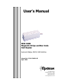
MCR 1000
Magnetic Stripe and Bar Code
Slot Reader
Keyboard Wedge, RS232, USB Interface
Manual No. 25-ULC1MU01-02
April, 2004
8 Olympic Drive
Orangeburg, NY 10962
Tel 845.365.0090
Fax 845.365.1251
www.OpticonUSA.com
Manual No. 25-ULC1MU01-01
MCR-1000 Bar Code / Magnetic Stripe Reader
Contents
Section 1 Introduction and Getting Started
Product Overview
Installing & Setting Up
3
3
3
Section 2 Technical Specifications
Physical Specifications
Symbologies Supported
Optical Specification
Magnetic Stripe Support
Electrical Specification
Environmental Specifications
5
5
5
5
5
5
5
Section 3 Programming the Slot Reader
Using Bar Codes to Program
Using Keyboard to Program
6
6
6
Section 4 General Programming Commands
8
Page 2
Manual No. 25-ULC1MU01-01
MCR-1000 Bar Code / Magnetic Stripe Reader
Section 1
Introduction and Getting Started
Product Overview
The MCR-1000 is a slot reader that is capable of reading either a bar code or (if equipped) magnetic
stripes on cards that are passed through the slot.
The MCR-1000 is available with several different interface configurations:
Keyboard Wedge Interface
RS232 Interface
USB Interface
Installation and Getting Starting
Determine which type of interface you have and follow the steps indicated under the appropriate section
A) RS232 Interface
The standard slot reader is terminated with a DB25 female connector. In many instances, an external
power supply will be needed to provide power for the slot reader unless the RS232 port on the receiving
device has +5 V DC on pin #25.
1. Plug the slot reader into an RS232 serial port (such as COM1) of the host PC. If external power is
required, utilize the patch cable available from Opticon.
2. Turn on the PC. Make sure the serial communications settings of the PC match those of the bar code
reader. The default communications settings are: 9600 baud, 8 bits, 1 stop bit, no parity, no
handshaking.
3. Connect the power supply into an electrical outlet (110V AC) and plug it into the jack on the patch
cable.
4. Be sure the PC is in a program (such as Hyperterminal or Listen 32) that will accept data input from
the serial port.
B) Keyboard Wedge interface
A “Y”cable is provided for installation. Connect the DB9 connector to the slot reader. Connect one leg of
cable into the keyboard port of your PC. (Be sure not to plug it into the mouse port.) Connect the
remaining leg to your keyboard.
C) USB Interface
1. Plug the slot reader into a USB port on your PC. There is no needed to turn off power to the PC
during installation. PC must be running Windows 98 or higher or Mac OS8.6 or higher.
2. Macintosh PC will automatically detect the slot reader and load the required drivers.
3. A Windows PC will recognize the presence of a new hardware device and prompt you through the
installation. Windows 98, for example, will open the dialog box: “Add New Hardware Wizard” which
will guide you through installation. Click NEXT
4. At the prompt “ What do you want Windows to do?”, select “Search for best driver” then click NEXT
5. At the prompt “Windows will search its driver database on your hard drive, click NEXT
6. At the prompt “Windows located a USB Human Interface Device”, click NEXT
7. At the prompt indicating that Windows has installed a specific driver, click FINISH
Page 3
Manual No. 25-ULC1MU01-01
MCR-1000 Bar Code / Magnetic Stripe Reader
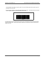
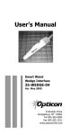
Your slot reader is now ready to scan bar codes! Cut out the following bar code (or make a copy of it)
and paste it onto a 3x5 card.
Be sure that there is about ¼ inch of white space below the bar code. And make sure there is at least
½ inch of space on both the right and left sides of the bar code.
+23!567+
+23!567+
123456
Try scanning the bar code. Insert the card so that it rests on the bottom of the slot, with the bar code
facing the indicator light. Swipe the card quickly, taking care to ensure that it doesn’t raise up off the
bottom of the slot.
Page 4
Manual No. 25-ULC1MU01-01
MCR-1000 Bar Code / Magnetic Stripe Reader
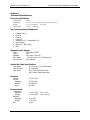
Section 2
Technical Specifications
Physical Specifications
Case Material
Dimensions
Weight
Cable Length
Plastic
4.9” x 1.9” x 1.6” (LxWxH) (125 x 47 x 40.5 mm)
4.6 oz (130 grams ) w/o cable
5 Feet (1500 mm)
Bar Code Symbologies Supported
♦
♦
♦
♦
♦
♦
♦
♦
Codabar (NW-7)
Code 39
Code 93
Code 128
Industrial 2 of 5 Interleaved 2 of 5
MSI / Plessey
WPC (UPC / EAN / JAN)
IATA
Magnetic Stripe Support
Type I
Type II
Standard
Scan Speed
Scan Direction
IATA, ABA, THRIFT
NTT
JIS x 6301 –Type I/II
3.9 to 59 in/sec (100 - 1500mm/sec)
Bi -Directional
Optical Bar Code Specifications
Scan Speed
Scan Direction
Light source
6 to 79 in/sec (150 - 940mm/sec)
Bi -Directional
660 ±10nm visible laser diode
940 ±10nm infrared laser diode
Electrical
Voltage
Current
Operating
Standby
Surge
5 V DC ±10%
100 mA max
60 mA max
3 A max
Environmental
Temperature
Operating
Storage
Humidity
Operating
Storage
ESD
+32 to +104 F (0 to +40 C)
+14 to +140 F (-10 to +60 C)
20 to 80%
20 to 90%
10 KV
Page 5
Manual No. 25-ULC1MU01-01
MCR-1000 Bar Code / Magnetic Stripe Reader
Section 3
Programming the Slot Reader
The slot reader is ready to use. It has been preprogrammed at the factory with the most common
settings. These factory default settings are ideal for most situations.
If you do wish to change certain parameters, this section of the manual contains the information that
allows you to easily change certain programmable parameters of the slot.
There are two different ways to change parameters in the slot reader. The method you choose may
depend on the type of interface in your reader.
A. All interface types (USB, RS232 and Wedge) can be changed or modified by swiping Programming
Command Bar Codes through the slot reader in a particular sequence.
B. For those slot readesr with Wedge or RS232 interface, the keyboard can be used to enter
Programming Commands that are transmitted to the slot reader to change parameters.
A. Using Bar Codes To Program
Programming using bar codes is easy is an easy way of changing parameters. There is a specific
bar code associated with each parameter. Reading that bar code changes the settings within the
slot reader.
To select menu options:
1) Scan the bar code for “Start/End Program Menu”. The slot reader will beep continuously
to indicate that it is ready to be programmed.
2) Select the bar code associated with the parameter selection from menu. Scan that bar code
by swiping it through the slot (a beep and a green light indicate that the parameter has
been scanned).
3) Scan the bar code for “Start/End Program Menu”. This completes the operation and the
new parameter is saved in memory.
B. Using the Keyboard to Program
To program an RS-232 slot reader from the keyboard, open a Terminal Program such as Hyperterminal.
Initially, set communication parameters to default: 9600 Baud, no parity, 8 data bits, 1 stop bit, no
handshaking.
The command format is as follows:
<ESC><command><CR>
To program a Wedge slot reader from the keyboard, open a Text Program such as Notepad or a similar
text editing or word processing program, such as Word.
Page 6
Manual No. 25-ULC1MU01-01
MCR-1000 Bar Code / Magnetic Stripe Reader
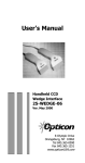
1) Slide the “ZK” bar code through the slot reader to enable keyboard programming. The
reader will beep to indicate it’s ready for keyboard commands.
ZK
[L
2) Set the CAPS LOCK.
3) Select the 2 characters representing the desired function from the left hand column of the
programming menu. Type the 2 characters and ENTER for each command. The scanner
will beep to indicate the command was accepted.
4) When all commands have been entered, type ZK and ENTER to finish programming.
NOTE: If any mistakes are made in programming, scanning or entering the U1 command will
return the slot reader to Default settings.
Most of the parameters, except those related to RS-232 communication (e.g. baud rate, data
bits) can be changed by sending a command to the slot reader from the host. The parameters
chosen this way are only effective while the power is supplied to the slot reader, and will be lost
as soon as the power is switched off. To make the new setting permanent, the save settings
command “Z2” can be sent to the slot reader after all changes have been made.
Technical Support
Opticon’s experienced technical staff is available during regular business hours to answer questions
and assist you in every way possible in support of our products, at (800) 636-0090.
When calling Opticon Technical Support, please have the unit model number and several bar code
labels readily at hand. The model number is located near the connector end of the cable.
Page 7
Manual No. 25-ULC1MU01-01
MCR-1000 Bar Code / Magnetic Stripe Reader
Section 4
General Programming Commands
The following tables contain a menu of various parameters or functions that can be changed or modified.
The description of the function is contained in the center column. The Programming Command bar code
is in the right hand column and the Computer Keyboard Command is in the left hand column.
To utilize the Programming Command, some users find it easier to cut out the programming bar code (or
make a copy) and paste it to a 3x5 card. Be sure the bar code itself is only ¼ inch from the bottom of
the card. Swipe these programming bar code(s) through the slot reader in the correct sequence to
change or modify the desired parameters.
1. Scan the bar code for “Start/End Program Menu”. The slot reader will beep continuously to
indicate that it is ready to be programmed.
2. Select the bar code associated with the parameter selection from the menu. Scan that bar code by
swiping it through the slot (a beep and a green light indicates that the parameter has been
scanned).
3. Scan the bar code for “Start/End Program Menu”. This completes the operation and the new
parameter(s) is saved in memory.
!
Factory Defaults
Page 8
Manual No. 25-ULC1MU01-01
MCR-1000 Bar Code / Magnetic Stripe Reader
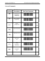
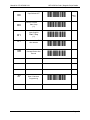
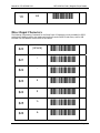
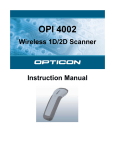
General Commands
Computer
Command
ZK
Function /
Description
Bar Code Command
Start Keyboard
Programming
(Wedge Only)
[L
Start / End Menu
Programming
[8
Defaults
No Mag Tracks
V2
American Keyboard
LV
Mag Track 1 Only
8C
Mag Tracks
1&2
8J
P1
USB
Power 100 mA
(USB Only)
Q2
WC
Caps Default
ON
XD
Z7
U1
KU
7B
7I
!
Page 9
Manual No. 25-ULC1MU01-01
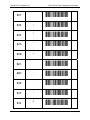
XC
D0
D1
MCR-1000 Bar Code / Magnetic Stripe Reader
Caps Default OFF
Remove Code39
Start / Stop
(*/ *)
Insert Code39
Start / Stop
(*/ *)
XT
Do not transmit a TAB
after decode
XR
Do not transmit a
Carriage Return after
decode
Z7
Start / End Menu
Programming
YD
!
E1
E2
YU
YS
[8
Page 10
Manual No. 25-ULC1MU01-01
MCR-1000 Bar Code / Magnetic Stripe Reader
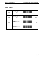
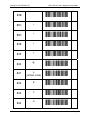
Code Enable
B6
Enable Code
128
C7
4N
Disable Code
128
5O
!
B4
Enable I –2 of 5
C5
!
4J
Disable I –2 of 5
5K
Page 11
Manual No. 25-ULC1MU01-01
MCR-1000 Bar Code / Magnetic Stripe Reader
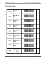
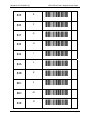
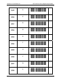
Prefixes & Suffixes
M4
Set Code 39
Prefix
N5
O4
Set Code 39
Suffix
P5
N1
Set UPC-A
Prefix
O2
N6
Set UPC-A
Suffix
O7
M9
Set Code 128
Prefix
N:
O9
Set Code 128
Suffix
P:
MA
Set Mag IATA
Prefix
NB
OA
Set Mag IATA
Suffix
MB
Set Mag ABA
Prefix
PB
NC
Page 12
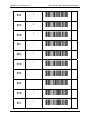
Manual No. 25-ULC1MU01-01
MCR-1000 Bar Code / Magnetic Stripe Reader
OB
Set Mag ABA
Suffix
PC
1Y
Clear All
Prefixes
2Z
1Z
Clear All
Suffixes
2[
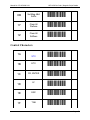
Control Characters
1A
STX
1B
ETX
1C
CR, ENTER
1D
LF
1E
ESC
1F
TAB
2B
2C
2D
2E
2F
2G
Page 13
Manual No. 25-ULC1MU01-01
1H
MCR-1000 Bar Code / Magnetic Stripe Reader
BS
2I
Direct Input Characters
The following Programming Commands for the Direct Input of Characters are only available for RS232
and Keyboard Wedge interface slot readers with software version DM05J13 and above, and for USB
interface unit with software version DU01J05 and above
$20
[SPACE]
$21
!
$22
“
$23
#
$24
$
$25
%
$26
&
%31
%32
%33
%3!
%35
%36
%37
Page 14
Manual No. 25-ULC1MU01-01
MCR-1000 Bar Code / Magnetic Stripe Reader
$27
‘
$28
(
$29
)
$2A
*
$2B
+
$2C
,
$2D
-
$2E
.
$2F
/
$30
0
%38
%39
%3:
%3B
%3C
%3D
%3E
%3F
%3G
%!1
Page 15
Manual No. 25-ULC1MU01-01
MCR-1000 Bar Code / Magnetic Stripe Reader
$31
1
$32
2
$33
3
$34
4
$35
5
$36
6
$37
7
$38
8
$39
9
$3A
:
%!2
%!3
%!!
%!5
%!6
%!7
%!8
%!9
%!:
%!B
Page 16
Manual No. 25-ULC1MU01-01
MCR-1000 Bar Code / Magnetic Stripe Reader
$3B
;
$3C
<
$3D
=
$3E
>
$3F
?
$40
@
$41
A
(UPPER CASE)
$42
B
$43
C
$44
D
%!C
%!D
%!E
%!F
%!G
%51
%52
%53
%5!
%55
Page 17
Manual No. 25-ULC1MU01-01
MCR-1000 Bar Code / Magnetic Stripe Reader
$45
E
$46
F
$47
G
$48
H
$49
I
$4A
J
$4B
K
$4C
L
$4D
M
$4E
N
%56
%57
%58
%59
%5:
%5B
%5C
%5D
%5E
%5F
Page 18
Manual No. 25-ULC1MU01-01
MCR-1000 Bar Code / Magnetic Stripe Reader
$4F
O
$50
P
$51
Q
$52
R
$53
S
$54
T
$55
U
$56
V
$57
W
$58
X
%5G
%61
%62
%63
%6!
%65
%66
%67
%68
%69
Page 19
Manual No. 25-ULC1MU01-01
MCR-1000 Bar Code / Magnetic Stripe Reader
$59
Y
$5A
Z
$5B
[
$5C
\
$5D
]
$5E
^
$5F
_
$60
`
$7B
{
$7C
|
%6:
%6B
%6C
%6D
%6E
%6F
%6G
%71
%8C
%8D
Page 20
Manual No. 25-ULC1MU01-01
MCR-1000 Bar Code / Magnetic Stripe Reader
$7D
}
$7E
~
$7F
[DEL]
%8E
%8F
%8G
Page 21
Manual No. 25-ULC1MU01-01
MCR-1000 Bar Code / Magnetic Stripe Reader
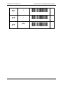
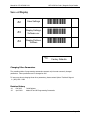
Save or Display
[3
Z2
Save Settings
Z3
Display Settings,
Software ver.
[!
Z4
Display Prefixes,
Suffixes
[5
!
Factory Defaults
Changing Other Parameters
The preceding tables of programming commands represent only the most commonly changed
parameters. Other parameters can be changed as well.
To learn more about changing these other parameters, please contact Opticon Technical Support:
1 – (800) 636 – 0090
Revision History
-01
-02
Feb 2003
April 2004
Initial Release
Added XT and XR Programming Commands
Page 22