1
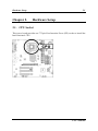
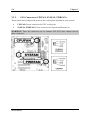
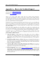
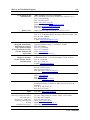
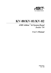
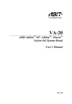
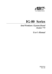
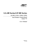
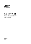
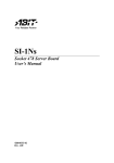
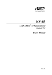
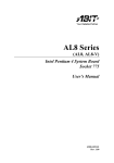
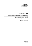
SG-80 Series
(SG-80, SG-81)
Intel Pentium 4 System Board
Socket 775
User’s Manual
Rev. 1.00
Copyright and Warranty Notice
The information in this document is subject to change without notice and does not
represent a commitment on part of the vendor, who assumes no liability or
responsibility for any errors that may appear in this manual.
No warranty or representation, either expressed or implied, is made with respect to the
quality, accuracy or fitness for any particular part of this document. In no event shall
the manufacturer be liable for direct, indirect, special, incidental or consequential
damages arising from any defect or error in this manual or product.
Product names appearing in this manual are for identification purpose only and
trademarks and product names or brand names appearing in this document are
property of their respective owners.
This document contains materials protected under International Copyright Laws. All
rights reserved. No part of this manual may be reproduced, transmitted or transcribed
without the expressed written permission of the manufacturer and authors of this
manual.
SG-80 Series
Table of Contents
Chapter 1.
1.1.
1.2.
1.3.
1.4.
Chapter 2.
2.1.
2.2.
2.3.
Chapter 3.
3.1.
Introduction .................................................... 1-1
Features & Specifications....................................................... 1-1
Layout Diagram (SG-80)........................................................ 1-3
Layout Diagram (SG-81)........................................................ 1-4
Jumpers & Connectors Description........................................ 1-5
Hardware Setup.............................................. 2-1
CPU Socket ............................................................................ 2-1
System Memory ..................................................................... 2-2
Connectors, Headers, and Switches ....................................... 2-3
2.3.1. ATX Power Connectors (ATX_POWER, ATX12V) 2-3
2.3.2. FAN Connectors (CPUFAN, SYSFAN, PWRFAN). 2-4
2.3.3. CMOS Memory Clearing Header (CCMOS) ........... 2-5
2.3.4. Front Panel Switches & Indicators Connection
Headers (PANEL1) ................................................... 2-6
2.3.5. Additional USB Port Connection Header (USB3,
USB4) ....................................................................... 2-7
2.3.6. Front Panel Audio Connection Header
(FPIO-AUDIO1)....................................................... 2-8
2.3.7. Accelerated Graphics Port Slot (AGP1)................... 2-9
2.3.8. Internal Audio Source Connectors (CD1, AUX1) .. 2-10
2.3.9. Floppy Disk Drive Connector (FDC) ..................... 2-11
2.3.10. IDE Disk Drive Connectors (IDE1, IDE2)............. 2-12
2.3.11. Serial ATA connectors (SATA1, SATA2) ............... 2-13
2.3.12. External I/O Panel................................................... 2-14
BIOS Setup...................................................... 3-1
About the Setup Utility........................................................... 3-1
3.1.1. The Standard Configuration ..................................... 3-1
3.1.2. Entering the Setup Utility ......................................... 3-2
3.1.3. Updating the BIOS ................................................... 3-3
User’s Manual
3.2.
Chapter 4.
4.1.
Using BIOS ............................................................................ 3-4
3.2.1. Standard CMOS Features ......................................... 3-4
3.2.2. Advanced BIOS Features ......................................... 3-7
3.2.3. Advanced Chipset Features .................................... 3-10
3.2.4. Integrated Peripherals ............................................. 3-14
3.2.5. Power Management Setup ...................................... 3-18
3.2.6. PnP/PCI Configurations.......................................... 3-20
3.2.7. PC Health Status ..................................................... 3-22
3.2.8. Frequency Control .................................................. 3-23
3.2.9. Load Fail-Safe Defaults Option.............................. 3-23
3.2.10. Load Optimized Defaults Option ........................... 3-24
3.2.11. Set Password ........................................................... 3-24
3.2.12. Save & Exit Setup Option....................................... 3-25
3.2.13. Exit Without Saving................................................ 3-25
Driver Installation .......................................... 4-1
Setup Items ............................................................................. 4-2
Appendix A. How to Get Technical Support ..................... A-1
SG-80 Series
Introduction
1-1
Chapter 1.
Introduction
1.1. Features & Specifications
CPU
•
•
Designed for Intel® 90nm Pentium 4/Celeron D LGA775 Processors
with 800/533 MHz FSB
Supports Intel Hyper-Threading Technology
Chipset
•
SIS 661FX/ 964 (L)
Memory
•
•
•
Two 184-pin DIMM sockets
Supports DDR400 non-ECC un-buffered memory
Supports maximum memory capacity up to 2GB
Graphic
•
Integrated SIS Mirage Graphics GPU high performance 256-bit 3D
engine and 2D Accelerator
SATA 150 (Option)
•
•
Serial ATA 1.5Gbps data transfer rate
Support SW RAID 0/ 1/ JBOD
LAN
•
Onboard 10/100 PHY
Audio
•
On board 5.1 channels Audio CODEC
Internal I/O Connectors
•
•
•
•
•
•
1x AGP 8X/4X slot. 3x PCI slots
1x Floppy Port supports up to 2.88MB
2x Ultra DMA 133/100/66/33 Connectors
2x Serial ATA 1.5Gbps Connectors (Option)
2x USB 2.0 headers (Each header support two USB 2.0 devices)
1x FP-Audio header, 1 x CD-IN, 1 x AUX-IN
User’s Manual
1-2
Chapter 1
Back Panel I/O
•
•
•
•
1x PS/2 Keyboard, 1x PS/2 Mouse
1x Serial Port, 1x Parallel Port, 1x VGA connector
4x USB 2.0, 1x RJ-45 LAN Connector
1x Audio connectors (Line-out, Line-in, MIC-in)
Miscellaneous
•
Micro ATX form factor (244mm x 244mm)
Product List
Model
Chipset
Features
SG-80
SIS 661FX + 964
10/100 LAN + SATA
SG-81
SIS 661FX + 964L
10/100 LAN
All brand names and trademarks are the property of their respective
owners.
This motherboard is customized for certain system configurations; and
may not fit system integration in all DIY ways. Before integrating this
product, please check ABIT web site for recommended device listings, or
contact sales/tech. support people.
Specifications and information contained herein are subject to change
without notice.
SG-80 Series
Introduction
1-3
1.2. Layout Diagram (SG-80)
User’s Manual
1-4
1.3. Layout Diagram (SG-81)
SG-80 Series
Chapter 1
Introduction
1-5
1.4. Jumpers & Connectors Description
Jumpers
Description
Default Setting
CCMOS
CMOS Memory Clearing Header
Pins 2-3 Closed (Normal)
Connectors
Description
AGP1
Accelerated Graphics Port Slot
ATX_POWER
ATX12V
ATX Power Connectors
CD1/AUX1
Internal Audio Connectors
CPUFAN
SYSFAN/PWRFAN
CPU Fan Power Connector
System/Power Fan Power Connectors
DIMM1/DIMM2
DDR DIMM Slots
FDC1
Floppy Disk Drive Connector
FPIO_AUDIO1
Front Panel Audio Connection Header
IDE1/IDE2
Hard Disk Drive Connectors
PANEL1
Front Panel Switch Connection Headers
PCI1/PCI2/PCI3
32bit/33MHz PCI Slots
SATA1/SATA2
Serial ATA connectors
USB3/USB4
Additional USB Port Connection Headers
User’s Manual
1-6
SG-80 Series
Chapter 1
Hardware Setup
Chapter 2.
2-1
Hardware Setup
2.1. CPU Socket
This server board provides one 775-pin Zero Insertion Force (ZIF) socket to install the
Intel Pentium 4 CPU.
User’s Manual
2-2
Chapter 2
2.2. System Memory
This system board provides two 184-pin DDR DIMM slots for un-buffered and
non-ECC modules with memory size expansible up to 2GB (DDR400).
DIMM
DIMM Module
Total Memory
1
256MB, 512MB, 1GB
256MB ~ 1GB
2
256MB, 512MB, 1GB
256MB ~ 1GB
Total System Memory
SG-80 Series
256MB ~ 2GB
Hardware Setup
2-3
2.3. Connectors, Headers, and Switches
All the connectors, headers and switches mentioned here are depending on your
system configuration. Some features you may (or may not) have to connect or to
configure depending on the peripherals you have connected.
WARNING: Always power off the computer and unplug the AC power cord before
adding or removing any peripheral or component. Failing to so may cause severe
damage to your system board and/or peripherals. Plug in the AC power cord only after
you have carefully checked everything.
2.3.1.
ATX Power Connectors (ATX_POWER, ATX12V)
This connector provides the connection to ATX12V power supply.
User’s Manual
2-4
2.3.2.
Chapter 2
FAN Connectors (CPUFAN, SYSFAN, PWRFAN)
These connectors each provide power to the cooling fans installed in your system.
•
CPUFAN: Power connector for CPU cooling fan
•
SYSFAN, PWRFAN: Power connector for System and Power Fan
WARNING: These fan connectors are not jumpers. DO NOT place jumper caps on
these connectors.
SG-80 Series
Hardware Setup
2.3.3.
2-5
CMOS Memory Clearing Header (CCMOS)
This header uses a jumper cap to clear the CMOS memory.
•
Pin 2-3 shorted (default): Normal operation.
•
Pin 1-2 shorted: Clear CMOS memory.
ATTENTION: Turn the system power off first (including the +5V standby power)
before clearing the CMOS memory. Failing to do so may cause your system to work
abnormally or malfunction.
User’s Manual
2-6
2.3.4.
Chapter 2
Front Panel Switches & Indicators Connection Headers
(PANEL1)
These headers are used for connecting switches and LED indicators on the chassis
front panel. The mark “+” align to the pin in the figure below stands for positive
polarity for the LED connection.
SG-80 Series
Pin
Definition
Pin
Definition
1
HD LED +
2
Message LED +
3
HD LED -
4
Message LED -
5
RESET
6
Power Switch
7
RESET
8
Power Switch
9
Reserved
10
NC
Hardware Setup
2.3.5.
2-7
Additional USB Port Connection Header (USB3, USB4)
These headers each provide 2 additional USB 2.0 ports connection through an USB
cable designed for USB 2.0 specifications.
Pin Signal Name
Function
1
USBPWR
Front Panel USB Power
2
USBPWR
Front Panel USB Power
3
USB_FP_P0-
USB Port 0 Negative Signal
4
USB_FP_P1-
USB Port 1 Negative Signal
5
USB_FP_P0+
USB Port 0 Positive Signal
6
USB_FP_P1+
USB Port 1 Positive Signal
7
GND
Ground
8
GND
Ground
9
Key
No pin
10 NC
NC
User’s Manual
2-8
2.3.6.
Chapter 2
Front Panel Audio Connection Header (FPIO-AUDIO1)
This header provides the connection to audio connector at front panel.
•
To use the audio connector at front panel, remove all the jumpers on this
header, and then connect to front panel by the extension cable provided with
the chassis.
•
To use the audio connector at rear panel, disconnect the extension cable,
attach the jumpers back at pin 5-6, and pin 9-10 (default setting).
Pin
1
2
3
4
5
Signal Name
AUD_MIC
AUD_GND
AUD_MIC_BIAS
AUD_VCC Filtered
AUD_F_R
6
AUD_RET_R
7
8
9
REVD
Key
AUD_F_L
10
AUD_RET_L
SG-80 Series
Function
Front Panel Microphone input signal
Ground used by Analog Audio Circuits
Microphone Power
+5V used by Analog Audio Circuits
Right Channel audio signal to Front Panel
Right Channel Audio signal to Return from
Front Panel
Reserved
No Pin
Left Channel Audio signal to Front Panel
Left Channel Audio signal to Return from Front
Panel
Hardware Setup
2.3.7.
2-9
Accelerated Graphics Port Slot (AGP1)
This slot supports an optional AGP graphics card up to AGP 8X/4X mode.
ATTENTION: This motherboard does not support 3.3V AGP cards. Use only 1.5V
or 0.8V AGP cards.
User’s Manual
2-10
2.3.8.
Chapter 2
Internal Audio Source Connectors (CD1, AUX1)
These connectors connect to the audio output of internal CD-ROM drive or add-on
card.
SG-80 Series
Hardware Setup
2.3.9.
2-11
Floppy Disk Drive Connector (FDC)
This connector supports two standard floppy disk drives via a 34-pin 34-conductor
ribbon cable.
Connecting the Floppy Disk Drive Cable:
1. Install one end of the ribbon cable into the FDC connector. The colored edge of
the ribbon cable should be aligned with pin-1 of FDC connector.
2. Install the other end(s) of ribbon cable into the disk drive connector(s). The
colored edge of the ribbon cable should be also aligned with pin-1 of disk drive
connector. The endmost connector should be attached to the drive designated as
Drive A.
User’s Manual
2-12
2.3.10.
Chapter 2
IDE Disk Drive Connectors (IDE1, IDE2)
These IDE ports each connects up to two
IDE drives at Ultra ATA/100 mode by one
40-pin, 80-conductor, and 3-connector Ultra
ATA/66 ribbon cables. Connect the single
end (blue connector) at the longer length of
ribbon cable to the IDE port on system
board, and the other two ends (gray and
black connector) at the shorter length of the
ribbon cable to the connectors on hard
drives.
NOTE: The red line on the ribbon cable should be aligned with pin-1 on this
connector.
SG-80 Series
Hardware Setup
2.3.11.
2-13
Serial ATA connectors (SATA1, SATA2)
These connectors are provided to attach one Serial ATA device at each channel via
Serial ATA cable.
User’s Manual
2-14
2.3.12.
Chapter 2
External I/O Panel
•
Mouse: PS/2 mouse connector.
•
Keyboard: PS/2 keyboard connector.
•
LPT1: Parallel port connector.
•
COM1: Serial port connector.
•
VGA1: Monitor signal connector.
•
USB1/USB2: USB 2.0 connectors.
•
LAN1:10/100Mbps LAN connectors.
•
AUDIO:
Mic In: Connects to the plug from external microphone.
Line In: Connects to the line out from external audio sources.
Line Out: Connects to the front left and front right channel in the 5.1-channel
or regular 2-channel audio system.
SG-80 Series
BIOS Setup
Chapter 3.
3-1
BIOS Setup
3.1. About the Setup Utility
The computer uses the latest Award BIOS with support for Windows Plug and Play.
The CMOS chip on the motherboard contains the ROM setup instructions for
configuring the motherboard BIOS.
The BIOS (Basic Input and Output System) Setup Utility displays the system’s
configuration status and provides you with options to set system parameters. The
parameters are stored in battery-backed-up CMOS RAM that saves this information
when the power is turned off. When the system is turned back on, the system is
configured with the values you stored in CMOS.
The BIOS Setup Utility enables you to configure:
•
Hard drives, diskette drives and peripherals
•
Video display type and display options
•
Password protection from unauthorized use
•
Power Management features
The settings made in the Setup Utility affect how the computer performs. Before
using the Setup Utility, ensure that you understand the Setup Utility options.
This chapter provides explanations for Setup Utility options.
3.1.1.
The Standard Configuration
A standard configuration has already been set in the Setup Utility. However, we
recommend that you read this chapter in case you need to make any changes in the
future.
This Setup Utility should be used:
•
when changing the system configuration
•
when a configuration error is detected and you are prompted to make changes
to the Setup Utility
•
when trying to resolve IRQ conflicts
•
when making changes to the Power Management configuration
•
when changing the password or making other changes to the Security Setup
User’s Manual
3-2
Chapter 3
3.1.2.
Entering the Setup Utility
When you power on the system, BIOS enters the Power-On Self Test (POST) routines.
POST is a series of built-in diagnostics performed by the BIOS. After the POST
routines are completed, the following message appears:
Press <DEL> to enter SETUP
Pressing the <Delete> key accesses the BIOS Setup Utility:
BIOS Navigation Keys
The BIOS navigation keys are listed below:
KEY
FUNCTION
ESC
Exits the current menu
←↑↓→
Scrolls through the items on a menu
+/-/PU/PD
Modifies the selected field’s values
F10
Saves the current configuration and exits setup
F1
Displays a screen that describes all key functions
F5
Loads previously saved values to CMOS
F6
Loads a minimum configuration for troubleshooting
F7
Loads an optimum set of values for peak performance
SG-80 Series
BIOS Setup
3.1.3.
3-3
Updating the BIOS
You can download and install updated BIOS for this motherboard from the
manufacturer’s Web site. New BIOS provides support for new peripherals,
improvements in performance, or fixes for known bugs.
Install new BIOS as follows:
1. If your motherboard has a BIOS protection jumper, change the setting to allow
BIOS flashing.
2. If your motherboard has an item called Firmware Write Protect in Advanced
BIOS features, disable it. (Firmware Write Protect prevents BIOS from being
overwritten.)
3. Create a bootable system disk. (Refer to Windows online help for information
on creating a bootable system disk.)
4. Download the Flash Utility and new BIOS file from the manufacturer’s Web
site. Copy these files to the system diskette you created in Step 3.
5. Turn off your computer and insert the system diskette in your computer’s
diskette drive. (You might need to run the Setup Utility and change the boot
priority items on the Advanced BIOS Features Setup page, to force your
computer to boot from the floppy diskette drive first.)
6. At the A:\ prompt, type the Flash Utility program name and press <Enter>.
7. Type the filename of the new BIOS in the “File Name to Program” text box.
Follow the onscreen directions to update the motherboard BIOS.
8. When the installation is complete, remove the floppy diskette from the diskette
drive and restart your computer. If your motherboard has a Flash BIOS jumper,
reset the jumper to protect the newly installed BIOS from being overwritten.
User’s Manual
3-4
Chapter 3
3.2. Using BIOS
When you start the Setup Utility, the main menu appears. The main menu of the Setup
Utility displays a list of the options that are available. A highlight indicates which
option is currently selected. Use the cursor arrow keys to move the highlight to other
options. When an option is highlighted, execute the option by pressing <Enter>.
Some options lead to pop-up dialog boxes that prompt you to verify that you wish to
execute that option. Other options lead to dialog boxes that prompt you for
information.
Some options (marked with a triangle ►) lead to submenus that enable you to change
the values for the option. Use the cursor arrow keys to scroll through the items in the
submenu.
In this manual, default values are enclosed in parenthesis. Submenu items are denoted
by a triangle ►.
3.2.1.
Standard CMOS Features
This option displays basic information about your system.
Date and Time
The Date and Time items show the current date and time on the computer. If you are
running a Windows OS, these items are automatically updated whenever you make
changes to the Windows Date and Time Properties utility.
SG-80 Series
BIOS Setup
3-5
IDE Devices (None)
Your computer has two IDE channels (Primary and Secondary) and each channel can
be installed with one or two devices (Master and Slave). Use these items to configure
each device on the IDE channel.
This motherboard features two SATA connectors supporting two SATA drives.
SATA refers to Serial ATA (Advanced Technology Attachment), the standard
interface for the IDE hard drives which are currently used in most PCs.
Press <Enter> to display the IDE submenu:
IDE HDD Auto-Detection
Press <Enter> while this item is highlighted to prompt the Setup Utility to
automatically detect and configure an IDE device on the IDE channel.
NOTE: If you are setting up a new hard disk drive that supports LBA mode, more
than one line will appear in the parameter box. Choose the line that lists LBA for an
LBA drive.
IDE Channel 1/2 Master/Slave/ IDE Drive(Auto)
Leave this item at Auto to enable the system to automatically detect and configure
IDE devices on the channel. If it fails to find a device, change the value to Manual and
then manually configure the drive by entering the characteristics of the drive in the
items described below.
User’s Manual
3-6
Chapter 3
Refer to your drive’s documentation or look on the drive casing if you need to obtain
this information. If no device is installed, change the value to None.
NOTE: Before attempting to configure a hard disk drive, ensure that you have the
configuration information supplied by the manufacturer of your hard drive. Incorrect
settings can result in your system not recognizing the installed hard disk.
Access Mode (Auto)
This item defines ways that can be used to access IDE hard disks such as LBA (Large
Block Addressing). Leave this value at Auto and the system will automatically decide
the fastest way to access the hard disk drive.
Press <Esc> to return to the Standard CMOS Features page.
Drive A/Drive B (1.44M, 3.5 in./None)
These items define the characteristics of any diskette drive attached to the system.
You can connect one or two diskette drives.
Floppy 3 Mode Support (Disabled)
Floppy 3 Mode refers to a 3.5-inch diskette with a capacity of 1.2 MB. Floppy 3
Mode is sometimes used in Japan.
Video (EGA/VGA)
This item defines the video mode of the system. This motherboard has a built-in VGA
graphics system; you must leave this item at the default value.
Halt On (All, But Keyboard)
This item defines the operation of the system POST (Power On Self Test) routine.
You can use this item to select which types of errors in the POST are sufficient to halt
the system.
Base Memory, Extended Memory, and Total Memory
These items are automatically detected by the system at start up time. These are
display-only fields. You cannot make changes to these fields.
SG-80 Series
BIOS Setup
3.2.2.
3-7
Advanced BIOS Features
This option defines advanced information about your system.
CPU Feature
Scroll to this item and press <Enter> to view the following screen:
Users please note that this function is only available for Prescott CPUs.
User’s Manual
3-8
Chapter 3
Thermal Management
This item displays CPU’s temperature and enables you to set a safe temperature to
Prescott CPU.
TM2 Bus Ratio
This item represents the frequency (bus ratio) of the throttled performance state that
will be initiated when the on-die sensor goes from not hot to hot).
TM2 Bus VID
This item represents the voltage of the throttled performance state that will be initiated
when the on-die sensor goes from not hot to hot.
Limit CPUID MaxVal
This item can support Prescott CPUs for old OS. Users please note that under NT 4.0,
it must be set “Enabled”, while under WinXP, it must be set “Disabled”.
NX BIOS Control
When disabled, forces the NX feature flag to always return to 0.
Hard Disk Boot Priority
Scroll to this item and press <Enter> to view the following screen:
SG-80 Series
BIOS Setup
3-9
CPU L3 Cache (Enabled)
This item is only available when processors support L3. Some high-end processors
support L3. If the CPU do support L3, you may set this item to enable or disable.
Leave this item at the default value for better performance.
Hyper-Threading Technology (Enabled)
This item is only available when the chipset supports Hyper-Threading and you are
using a Hyper-Threading CPU.
Quick Power On Self Test (Enabled)
Enable this item to shorten the power on testing (POST) and have your system start up
faster. You might like to enable this item after you are confident that your system
hardware is operating smoothly.
First/Second/Third Boot Device (Floppy/Hard Disk/CDROM)
Use these three items to select the priority and order of the devices that your system
searches for an operating system at start-up time.
Boot Other Device (Enabled)
When enabled, the system searches all other possible locations for an operating
system if it fails to find one in the devices specified under the First, Second, and Third
boot devices.
Swap Floppy Drive [Disabled]
If you have two floppy diskette drives in your system, this item allows you to swap
the assigned drive letters so that drive A becomes drive B, and drive B becomes drive
A.
Boot Up Floppy Seek (Disabled)
If this item is enabled, it checks the size of the floppy disk drives at start-up time. You
don’t need to enable this item unless you have a legacy diskette drive with 360K
capacity.
Boot Up NumLock Status (On)
This item defines if the keyboard Num Lock key is active when your system is
started.
User’s Manual
3-10
Chapter 3
ATA 66/100 IDE Cable Msg. (Enabled)
This item enables or disables the display of the ATA 66/100 Cable MSG.
Security Option (Setup)
If you have installed password protection, this item defines if the password is required
at system start up, or if it is only required when a user tries to enter the Setup Utility.
Small Logo(EPA) Show
This item determines to show the EPA logo when booting.
3.2.3.
Advanced Chipset Features
These items define critical timing parameters of the motherboard. You should leave
the items on this page at their default values unless you are very familiar with the
technical specifications of your system hardware. If you change the values incorrectly,
you may introduce fatal errors or recurring instability into your system.
SG-80 Series
BIOS Setup
3-11
DRAM Clock/Timing Control:
Scroll to this item and press <Enter> to view the following screen:
DRAM Timing Control
Enables you to select the CAS latency time in HCLKs of 2, 2.5, or 3. The value is set
at the factory depending on the DRAM installed. Do not change the values in this
field unless you change specifications of the installed DRAM or the installed CPU.
DRAM CAS Latency:
This item controls the timing delay (in clock cycles) before the DRAM starts a read
command after receiving it.
RAS Active Time (tRAS):
This item allows you to set the amount of time a RAS can be kept open for multiple
accesses. High figures will improve performance.
RAS Precharge Time (tRP):
This is the duration of the time interval during which the Row Address Strobe signal
to a DRAM is held low during normal Read and Write Cycles. This is the minimum
interval between completing one read or write and starting another from the same
(non-page mode) DRAM. Techniques such as memory interleaving, or use of Page
Mode DRAM are often used to avoid this delay. Some chipsets require this parameter
in order to set up the memory configuration properly. The RAS Precharge value is
typically about the same as the RAM Access (data read/write) time.
User’s Manual
3-12
Chapter 3
RAS to CAS Delay (tRCD):
This is the amount of time a CAS is performed after a RAS. The lower the better, but
some DRAM does not support low figures.
Press <Esc> to return to the Advanced Chipset Features page.
AGP & P2P Bridge Control
Scroll to this item and press <Enter> to view the following screen:
AGP Aperture Size
This setting controls just how much system RAM can be allocated to AGP for video
purposes. The aperture is a portion of the PCI memory address range dedicated to
graphics memory address space. Host cycles that hit the aperture range are forwarded
to the AGP without any translation.
Graphic Window WR Combin (Enabled)
Use this item to enable or disable CPU support for WR Combin feature.
AGP Fast Write Support (Disabled)
This item lets you enable or disable the caching of display data for the video memory
of the processor.
SG-80 Series
BIOS Setup
3-13
AGP Data Rate (Auto)
This item allows users to set the AGP Data Rate by, Auto, 1X, 2X, 4X, or 8X,
depending on what speed the AGP card supports.
Press <Esc> to return to the Advanced Chipset Features page.
OnChip AGP Control
Scroll to this item and press <Enter> to view the following screen:
VGA Share Memory Size (32M)
This item allows you to select the shared memory size for VGA usage.
Press <Esc> to return to the Advanced Chipset Features screen.
System BIOS Cacheable (Disabled)
This feature is only valid when the system BIOS is shadowed. It enables or disables
the caching of the system BIOS ROM at F0000h-FFFFFh via the L2 cache. This
greatly speeds up accesses to the system BIOS.
Video RAM Cacheable (Disabled)
This feature enables or disables the caching of the video RAM at A0000h-AFFFFh
via the L2 cache.
User’s Manual
3-14
Chapter 3
3.2.4.
Integrated Peripherals
These options display items that define the operation of peripheral components on the
system’s input/output ports.
OnChip IDE Device
Scroll to this item and press <Enter> to view the following screen:
SG-80 Series
BIOS Setup
3-15
Internal PCI/IDE (Both)
Use these items to enable or disable the internal PCI IDE channels that are integrated
on the mainboard.
IDE DMA Transfer Access (Enabled)
This item allows you to enabled the transfer access of the IDE DMA.
IDE Burst Mode (Enabled)
This option, when enabled will instruct the system to send every write transaction to
the write buffer. Burstable transactions then burst onto the PCI bus and nonburstable
transactions do not.
OnChip SATA Controller (Enabled)
Enables or disables the onboard Serial ATA controller. Enable this item if you are to
install SATA devices onboard.
Serial ATA Mode (IDE)
Use this item to define the onboard SATA mode. Set this item to RAID if you are to
activate the RAID function of the SATA devices.
Press <Esc> to return to the Integrated Peripherals screen.
User’s Manual
3-16
Chapter 3
OnChip PCI Device
Scroll to this item and press <Enter> to view the following screen:
OnChip USB Controller (Enabled)
Enable this item if you plan to use the Universal Serial Bus ports on this mainboard.
OnChip AC97 Controller (Enabled)
Enables or disables the onboard AC97 audio function. Disable this item if you are
going to install a PCI audio add-on card.
OnChip LAN Controller (Enabled)
Enables and disables the onboard LAN chip.
LAN Boot ROM (Disabled)
Use this item to enable and disable the booting from the onboard LAN or a network
add-in card with a remote boot ROM installed.
SG-80 Series
BIOS Setup
3-17
Press <Esc> to return to the Integrated Peripherals screen.
Onboard SuperIO Device:
Scroll to this item and press <Enter> to view the following screen:
Onboard FDC Controller (Enabled)
This option enables the onboard floppy disk drive controller.
Onboard Serial Port 1 (3F8/IRQ4)
This option is used to assign the I/O address and interrupt request (IRQ) for onboard
serial port1 (COM1).
Onboard Parallel Port (378/IRQ7)
This option is used to assign the I/O address and interrupt request (IRQ) for the
onboard parallel port.
Parallel Port Mode (ECP)
Enables you to set the data transfer protocol for your parallel port. There are four
options: SPP (Standard Parallel Port), EPP (Enhanced Parallel Port), ECP (Extended
Capabilities Port), and ECP+EPP.
SPP allows data output only. Extended Capabilities Port (ECP) and Enhanced Parallel
Port (EPP) are bi-directional modes, allowing both data input and output. ECP and
EPP modes are only supported with EPP- and ECP-aware peripherals.
User’s Manual
3-18
Chapter 3
ECP Mode Use DMA (3)
When the onboard parallel port is set to ECP mode, the parallel port can use DMA3 or
DMA1.
Press <Esc> to return to the Integrated Peripherals screen.
Onboard 1394 Device (Enabled)
Enables and disables the onboard IEEE 1394 controller.
Init Display First (PCI Slot)
Use this item to specify whether your graphics adapter is installed in one of the PCI
slots or is integrated on the motherboard.
3.2.5.
Power Management Setup
This option lets you control system power management. The system has various
power-saving modes including powering down the hard disk, turning off the video,
suspending to RAM, and software power down that allows the system to be
automatically resumed by certain events.
ACPI Suspend Type (S3(STR))
Use this item to define how your system suspends. In the default, S1(POS), the
suspend mode is equivalent to a software power down. If you select S3 (STR), the
suspend mode is a suspend to RAM, i.e., the system shuts down with the exception of
a refresh current to the system memory.
SG-80 Series
BIOS Setup
3-19
Resume by USB from S3 (Disabled)
When set to Enabled, the system power will resume the system from a power saving
mode if there is any USB port activity.
Power On by PS2 Keyboard (Hot Key)
This option enables you to allow the keyboard activity to awaken the system from
power saving mode.
Power On by PS2 Mouse (Disabled)
This option enables you to allow the mouse activity to awaken the system from power
saving mode.
Wakeup By Ring (Disabled)
Use this item to enable LAN or modem activity to wakeup the system from a power
saving mode.
Wakeup By PME# of PCI (Enabled)
This item allows users to enable or disable PCI activity to wakeup the system from a
power saving mode.
Power Up by Alarm (Disabled)
When set to Enabled, the following three fields become available: Month Alarm, Day
of Month Alarm, and Time Alarm Upon arrival of the alarm time, it will instruct the
system to wake up.
When set to 0 (zero) for the day of the month, the alarm will power on your system
every day at the specified time.
Power Button Override:
Under ACPI (Advanced Configuration and Power management Interface) you can
create a software power down. In a software power down, the system can be resumed
by Wake Up Alarms. This item lets you install a software power down that is
controlled by the power button on your system. If the item is set to Instant-Off, then
the power button causes a software power down. If the item is set to Delay 4 Sec. then
you have to hold the power button down for four seconds to cause a software power
down.
Restore On AC Power Loss:
This item selects the system action after an AC power failure.
User’s Manual
3-20
Chapter 3
[Power Off]: When power returns after an AC power failure, the system’s power
remains off. You must press the Power button to power-on the system.
[Power On]: When power returns after an AC power failure, the system’s power will
be powered on automatically.
[Last State]: When power returns after an AC power failure, the system will return to
the state where you left off before power failure occurs. If the system’s power is off
when AC power failure occurs, it will remain off when power returns. If the system’s
power is on when AC power failure occurs, the system will power-on when power
returns.
3.2.6.
PnP/PCI Configurations
These options configure how PnP (Plug and Play) and PCI expansion cards operate in
your system. Both the ISA and PCI buses on the motherboard use system IRQs
(Interrupt ReQuests) and DMAs (Direct Memory Access). You must set up the IRQ
and DMA assignments correctly through the PnP/PCI Configurations Setup utility for
the motherboard to work properly. Selecting PnP/PCI Configurations on the main
program screen displays this menu:
Resources Controlled By (Auto(ESCD))
You should leave this item at the default Auto(ESCD). Under this setting, the system
dynamically allocates resources to Plug and Play devices as they are required.
SG-80 Series
BIOS Setup
3-21
If you cannot get a legacy ISA (Industry Standard Architecture) expansion card to
work properly, you might be able to solve the problem by changing this item to
Manual, and then opening up the IRQ Resources submenu.
In the IRQ Resources submenu, if you assign an IRQ to Legacy ISA, then that
Interrupt Request Line is reserved for a legacy ISA expansion card. Press <Esc> to
close the IRQ Resources submenu.
IRQ Resources
The submenu allows you to individually assign an interrupt type for interrupts IRQ-3
to IRQ-15.
In the IRQ Resources submenu, if you assign an IRQ to Legacy ISA, then that
Interrupt Request Line is reserved for a legacy ISA expansion card. Press <Esc> to
close the IRQ Resources submenu.
In the Memory Resources submenu, use the first item Reserved Memory Base to set
the start address of the memory you want to reserve for the ISA expansion card. Use
the section item Reserved Memory Length to set the amount of reserved memory.
Press <Esc> to close the Memory Resources submenu.
PCI/VGA Palette Snoop [Disabled]
This item is designed to overcome problems that can be caused by some non-standard
VGA cards. This board includes a built-in VGA system that does not require palette
snooping so you must leave this item disabled.
User’s Manual
3-22
Chapter 3
PIRQ_0 Use IRQ No. ~ PIRQ_7 Use IRQ No. [Auto]
This item specifies the IRQ number manually or automatically for the devices
installed on PCI slots.
3.2.7.
PC Health Status
On motherboards that support hardware monitoring, this item lets you monitor the
parameters for critical voltages, critical temperatures, and fan speeds.
CPU Shutdown Temperature (Disabled)
This item sets the temperature that would shutdown the system automatically in order
to prevent system overheats.
NOTE: This item only works for the OS with ACPI activated.
System Component Characteristics
These items allow end users and technicians to monitor data provided by the BIOS on
this motherboard. You cannot make changes to these fields.
SG-80 Series
BIOS Setup
3.2.8.
3-23
Frequency Control
This item enables you to set the clock speed and system bus for your system. The
clock speed and system bus are determined by the kind of processor you have
installed in your system.
Auto Detect DIMM/PCI Clk (Enabled)
When this item is enabled, BIOS will disable the clock signal of free DIMM/PCI
slots.
Spread Spectrum (Enabled)
If you enable spread spectrum, it can significantly reduce the EMI (Electro-Magnetic
Interference) generated by the system.
Clock Control By (Auto)
Use this item to set the CPU Host Clock frequency to Auto or by manual setting.
Select “Manual” to activate the following items and set each item manually.
3.2.9.
Load Fail-Safe Defaults Option
This option opens a dialog box that lets you install fail-safe defaults for all appropriate
items in the Setup Utility:
User’s Manual
3-24
Chapter 3
Press <Y> and then <Enter> to install the defaults. Press <N> and then <Enter> to not
install the defaults. The fail-safe defaults place no great demands on the system and
are generally stable. If your system is not functioning correctly, try installing the
fail-safe defaults as a first step in getting your system working properly again. If you
only want to install fail-safe defaults for a specific option, select and display that
option, and then press <F6>.
3.2.10.
Load Optimized Defaults Option
This option opens a dialog box that lets you install optimized defaults for all
appropriate items in the Setup Utility. Press <Y> and then <Enter> to install the
defaults. Press <N> and then <Enter> to not install the defaults. The optimized
defaults place demands on the system that may be greater than the performance level
of the components, such as the CPU and the memory. You can cause fatal errors or
instability if you install the optimized defaults when your hardware does not support
them. If you only want to install setup defaults for a specific option, select and display
that option, and then press <F7>.
3.2.11.
Set Password
When this function is selected, the following message appears at the center of the
screen to assist you in creating a password.
ENTER PASSWORD
Type the password, up to eight characters, and press <Enter>. The password typed
now will clear any previously entered password from CMOS memory. You will be
asked to confirm the password. Type the password again and press <Enter>. You may
also press <Esc> to abort the selection.
To disable password, just press <Enter> when you are prompted to enter password. A
message will confirm the password being disabled. Once the password is disabled, the
system will boot and you can enter BIOS Setup freely.
PASSWORD DISABLED
If you have selected “System” in “Security Option” of “BIOS Features Setup” menu,
you will be prompted for the password every time the system reboots or any time you
try to enter BIOS Setup.
If you have selected “Setup” at “Security Option” from “BIOS Features Setup” menu,
you will be prompted for the password only when you enter BIOS Setup.
Supervisor Password has higher priority than User Password. You can use Supervisor
Password when booting the system or entering BIOS Setup to modify all settings.
Also you can use User Password when booting the system or entering BIOS Setup but
can not modify any setting if Supervisor Password is enabled.
SG-80 Series
BIOS Setup
3.2.12.
3-25
Save & Exit Setup Option
Highlight this item and press <Enter> to save the changes that you have made in the
Setup Utility and exit the Setup Utility. When the Save and Exit dialog box appears,
press <Y> to save and exit, or press <N> to return to the main menu:
3.2.13.
Exit Without Saving
Highlight this item and press <Enter> to discard any changes that you have made in
the Setup Utility and exit the Setup Utility. When the Exit Without Saving dialog box
appears, press <Y> to discard changes and exit, or press <N> to return to the main
menu.
NOTE: If you have made settings that you do not want to save, use the “Exit Without
Saving” item and press <Y> to discard any changes you have made.
User’s Manual
3-26
SG-80 Series
Chapter 3
Driver Installation
Chapter 4.
4-1
Driver Installation
All the necessary drivers are included within the Drivers & Utilities CD that came
packaged with your board. The display shown in the following figure should appear
after inserting this CD into your CD-ROM drive, if not, enter [My Computer] [CD-ROM] Drive double click [autorun.exe]. Please follow the on-screen
instruction.
User’s Manual
4-2
Chapter 4
4.1. Setup Items
•
Drivers
Install the drivers for Windows Operating System.
•
Manual
View the user’s manual in PDF file.
•
Utility
Click to enter the sub-screen for installing software like Acrobat Reader,
Award Flash, DirectX, and LoFormat utility.
•
Browse CD
Browse the contents of this CD-ROM.
•
Close
Exit the CD setup Items Menu.
SG-80 Series
How to Get Technical Support
A-1
Appendix A. How to Get Technical Support
(From our website) http://www.abit.com.tw
(In North America) http://www.abit-usa.com
(In Europe) http://www.abit.nl
Thank you for choosing ABIT products. ABIT sells all our products through distributors,
resellers and system integrators; we have no direct sales to end-users. Before sending email for
tech support please check with your resellers or integrators if you need any services, they are the
ones who sold you your system and they should know best as to what can be done, how they
serve you is a good reference for future purchases.
We appreciate every customer and would like to provide the best service to you. Providing fast
service to our customers is our top priority. However we receive many phone calls and a huge
amount of email from all over the world. At the present time it is impossible for us to respond to
every single inquiry. Therefore it is quite possible that if you send an email to us that you may
not receive a response.
We have done many compatibility tests and reliability tests to make sure our products have the
best quality and compatibility. In case you need service or technical support, please understand
the constraint we have and always check with the reseller who sold the product to you first.
To expedite service, we recommend that you follow the procedures outlined below before
contacting us. With your help, we can meet our commitment to provide the best service to the
greatest number of ABIT customers:
1.
Check the Manual. It sounds simple but we have taken a lot of care in making a
well-written and thorough manual. It is full of information that doesn't only pertain to
motherboards. The CD-ROM included with your board will have the manual as well as
drivers. If you don't have either one, go to our Program Download Area of the Website or
FTP server.
2.
Download latest BIOS, software or drivers. Please go to our Program Download area on
our Website to check to see if you have the latest BIOS. They are developed over periods of
time to fixes bugs or incompatibilities. Also please make sure you have the latest drivers
from your peripheral cards makers!
3.
Check the ABIT Technical Terms Guide and FAQ on our Website. We are trying to
expand and make the FAQs more helpful and information rich. Let us know if you have any
suggestions. For hot topics check out our HOT FAQ!
4.
Internet Newsgroups. They are a great source of information and many people there can
offer help. ABIT's Internet News group, alt.comp.periphs.mainboard.abit, is an ideal forum
for the public to exchange information and discuss experiences they have had with ABIT
products. Many times you will see that your question has already been asked before. This is
a public Internet news group and it is reserved for free discussions. Here is a list of some of
the more popular ones:
User’s Manual
A-2
Appendix A
alt.comp.periphs.mainboard.abit
comp.sys.ibm.pc.hardware.chips
alt.comp.hardware.overclocking
alt.comp.hardware.homebuilt
alt.comp.hardware.pc-homebuilt
5.
Ask your reseller. Your ABIT authorized distributor should be able to provide the fastest
solution to your technical problem. We sell our products through distributors who sell to
resellers and stores. Your reseller should be very familiar with your system configuration
and should be able to solve your problem much more efficiently than we could. After all,
your reseller regards you as an important customer who may purchase more products and
who can urge your friends to buy from him or her as well. They integrated and sold the
system to you. They should know best what your system configuration is and your problem.
They should have reasonable return or refund policies. How they serve you is also a good
reference for your next purchase.
6.
Contacting ABIT. If you feel that you need to contact ABIT directly you can send email to
the ABIT technical support department. First, please contact the support team for the branch
office closest to you. They will be more familiar with local conditions and problems and will
have better insight as to which resellers offer what products and services. Due to the huge
number of emails coming in every day and other reasons, such as the time required for
problem reproduction, we will not be able to reply to every email. Please understand that we
are selling through distribution channels and don't have the resources to serve every end-user.
However, we will try to do our best to help every customer. Please also remember that for
many of our technical support team English is a second language, you will have a better
chance of getting a helpful answer if your question can be understood in the first place. Be
sure to use very, simple, concise language that clearly states the problem, avoid rambling or
flowery language and always list your system components. Here is the contact information
for our branch offices:
7. RMA Service. If your system has been working but it just stopped, but you have
not installed any new software or hardware recently, it is likely that you have a
defective component. Please contact the reseller from whom you bought the
product. You should be able to get RMA service there.
8. Reporting Compatibility Problems to ABIT. Because of tremendous number of
email messages we receive every day, we are forced to give greater weight to
certain types of messages than to others. For this reason, any compatibility
problem that is reported to us, giving detailed system configuration information
and error symptoms will receive the highest priority. For the other questions, we
regret that we may not be able to reply directly. But your questions may be posted
to the Internet news group in order that a larger number of users can have the
benefit of the information. Please check the news group from time to time.
SG-80 Series
How to Get Technical Support
North America and
South America
RMA Center
UK and Ireland
Germany and Benelux
(Belgium, Netherlands,
Luxembourg), France,
Italy, Spain, Portugal,
Greece, Denmark, Norway,
Sweden, Finland, and
Switzerland
Austria, Czech, Romania,
Bulgaria, Slovakia,
Croatia, Bosnia, Serbia,
and Macedonia
Shanghai
Russia and CIS
Poland
Japan
Taiwan Head Office
(Serving all other territories
not listed above.
Taiwan is 8+ GMT time,
and may have different
holiday
calendar from yours.)
A-3
ABIT Computer (U.S.A.) Corporation
45531 Northport Loop West, Fremont CA, 94538, U.S.A.
Tel: 1-510-623-0500
Fax: 1-510-623-1092
Sales: [email protected]
Latin America Sales: [email protected]
Marketing: [email protected]
Web Site: http://www.abit-usa.com
46808 Lakeview Blvd. Fremont, CA 94538, U.S.A.
ABIT Computer (U.K.) Corporation Ltd.
Unit 3, 24-26 Boulton Road, Stevenage, Herts SG1 4QX, UK
Tel: 44-1438-228888
Fax: 44-1438-226333
E-mail: [email protected]
AMOR Computer B.V. (ABIT's European Office)
Jan van Riebeeckweg 15, 5928LG, Venlo,
The Netherlands
Tel: 31-77-3204428
Fax: 31-77-3204420
Sales: [email protected]
Web Site: http://www.abit.nl
Asguard Computer Ges.m.b.H
Schmalbachstrasse 5, A-2201 Gerasdorf / Wien, Austria
Tel: 43-1-7346709
Fax: 43-1-7346713
E-mail: [email protected]
ABIT Computer (Shanghai) Co. Ltd.
Tel: 86-21-6235-1829
Fax: 86-21-6235-1832
Web Site: http://www.abit.com.cn
ABIT Computer (Russia) Co. Ltd.
Sales: [email protected]
Info: [email protected]
Web Site: http://www.abit.ru
ABIT Computer (Poland) Co. Ltd.
Przedstawicielstwo w Polsce ul. Wita Stwosza 28, 50-149
Wrocław
Tel: 48 71 780 78 65 / 66
Fax: 48 71 372 30 87
Web Site: http://www.abit4u.jp
ABIT Computer Corporation
No. 323, Yang Guang St., Neihu, Taipei, 114, Taiwan
Tel: 886-2-8751-8888
Fax: 886-2-8751-3382
Sales: [email protected]
Marketing: [email protected]
Web Site: http://www.abit.com.tw
User’s Manual
A-4
Appendix A
Technical Support Form
Company Name:
Phone Number:
Contact Person:
Fax Number:
E-mail Address:
Model
*
Motherboard Model No.
DRIVER REV
OS/Application
*
Hardware Name
Brand
CPU
HDD
CD-ROM-Drive
System Memory
ADD-ON CARD
Problem Description:
SG-80 Series
*
IDE1
IDE2
IDE1
IDE2
BIOS ID #
Specifications
*