1
Page: 1
Service Guide OL830
Chapter 0 About This Manual
OL830
LED Page Printer
Adobe Acrobat printable reference
copy of the OKIDATA Service Training Manual.
09/17/97
Note: This Adobe Acrobat version of the Okidata Service Training Manual was built with the
pictures rendered at 300 dpi, which is ideal for printing, but does not view on most
displays well.
Copyright 1997, Okidata, Division of OKI America, Inc. All rights reserved. See the OKIDATA Business
Partner Exchange (BPX) for any updates to this material. (http://bpx.okidata.com)
Table of Contents
Page
Service Guide OL830
0 About This Manual
Front Cover
Copyright
Manual Part Number & Revision
1 Product Specifications
1.1 Overview
1.2 Print Specifications
1.3 Paper Specifications
1.4 Physical Specifications
1.5 Power Requirements
1.6 Environmental Conditions
1.7 Agency Approvals
1.8 Consumables
1.9 Options
1.10 Reliability Data
2 Principles of Operation
2.1 Overview
........Block Diagram of PrinterTitle of Section
........Block Diagram of Main Control Board
2.2 Printer Overview
....2.2.02 Main Control Unit
....2.2.03 Main Controller Board (APSM)
....2.2.04 Emulation Board (APSH)
....2.2.05 Expansion RAM Board (REXM)
....2.2.06 Font Card
2.3 Printer Control Unit
....2.3.02 Engine Controller Board (LLAB-2)
........Block Diagram of Printer Unit
....2.3.03 Power Supply Unit
....2.3.04 Fuser Unit
....2.3.05 Main Motor (Drum Motor)
....2.3.06 LED Array
....2.3.07 Resist Motor
....2.3.08 DC Fan
....2.3.09 Operation Panel
....2.3.10 Sensor Functions
3 Maintenance & Disassembly
3.1 Maintenance
....3.1.02 Maintenance Tools
....3.1.03 Maintenance Precautions
3.2 Disassembly/Assembly Procedures
........Sequence of Procedures
1
2
3
4
5
6
7
8
9
10
11
12
13
14
15
16
17
18
19
20
21
22
23
24
25
26
27
28
29
30
31
32
33
34
35
36
37
38
Table of Contents
........Board Layout
....3.2.01 Upper Cover
....3.2.02 AppleTalk/Serial Interface Board (APSR) (Option)
....3.2.03 RAM Board (REXM) Option
....3.2.04 Emulation Board (APSH)
....3.2.05 Main Controller Board (APSM)
....3.2.06 Second Paper Feed Unit
3.3 Adjustments And Service Checks
....3.3.01 Actual Page Count
....3.3.02 Modified Page Count
....3.3.03 Vertical Print Start Position Adjustment
....3.3.04 Setting the LED Head Drive Time
....3.3.05 Resetting the Fuser Counter
....3.3.06 DC Voltage Adjustment (+5vdc)
3.4 Cleaning
....3.4.02 Static Charger
....3.4.03 Transfer Charger
....3.4.04 LED Lens Array
3.5 Lubrication
4 Failure & Repair Analysis
4.1 Overview
....4.1.02 Types of Problems
4.2 Troubleshooting Updates
4.3 Reporting Problems
4.4 Troubleshooting Tips
4.5 Fault Alarms
....4.5.02 Error Messages Table - SERVICE is Lit
........SERVICE is NOT Lit
........Jam Errors
........Tray Requests
........Manual Feed Requests
........Buffer Overflow / Reset Operation (Emulation Mode)
........Daily Status (Emulation Mode)
........Daily Status (PostScript Mode)
....4.5.03 Output Samples
4.6 Repair Analysis Procedures
....4.6.02 RAP Index
........RAP 01: Printer Does Not Initialize
........RAP 02: Paper Feed Jam 1 Alarm
........RAP 03: Paper Jam Alarm
........RAP 04: Paper Size Error (Size Tray 1 Error)
........RAP 05: Engine Error - Fusing Problem Alarm
........RAP 06: Engine Error Alarm
........RAP 07: Error Operator Panel Interface Timeout
Page
39
40
41
42
43
44
45
46
47
48
49
50
51
52
53
54
55
56
57
58
59
60
61
62
63
64
65
66
67
68
69
70
71
72
73
74
75
76
77
78
79
80
81
Table of Contents
........RAP 08: Communications Error PU and CU
........RAP 09: Loop Test Failure (RS232-C) - Emulation Mode
........RAP 10: Error Resident / Optional RAM Check
........RAP 11: Program ROM Failure
........RAP 12: No Operation Panel Display
........RAP 13: Light or Blurred Images
........RAP 14: Dark Background
........RAP 15: Blank Output
........RAP 16: Vertical Black Stripes
........RAP 17: Repeating Marks
........RAP 18: Blank Spots
........RAP 19: Vertical White Stripes
........RAP 20: Black Output
........RAP 21: Poor Fusing
4.7 Self-Tests
A Reference Charts
A.1 Overview
A.2 Charts - Index To Charts
........Board Layout
....A.2.01 Main Controller Board (APSM)
....A.2.02 Second Tray Connection Board (LLIF) Option
....A.2.03 AppleTalk/Serial Interface Board (APSR) Option
....A.2.04 Operation Panel Board (LLJA)
....A.2.05 Emulation Board (APSH)
B Illustrated Parts Listing
B.1 Overview
....B.1.02 Definitions of Terms
....B.1.03 Parts Ordering Information
B.2 Charts
....B.2.01 Printer Unit
....B.2.02 Upper Unit
....B.2.03 Fusing Unit
....B.2.04 Lower Unit (1 of 2)
....B.2.05 Lower Unit (2 of 2)
....B.2.06 Paper Eject Roller Assembly
....B.2.07 Paper Supply Unit
....B.2.08 Second Paper Tray Unit
....B.2.09 Packaging
Page
82
83
84
85
86
87
88
89
90
91
92
93
94
95
96
97
98
99
100
101
102
103
104
105
106
107
108
109
110
111
112
113
114
115
116
117
Page: 2
Service Guide OL830
Chapter 0 About This Manual
This document may not be reproduced without written permission of the Okidata® Technical
Training Group. Every effort has been made to ensure the accuracy of the information contained
in this training course. Okidata is not responsible for errors beyond its control.
© 1994 by Okidata All rights reserved.
First Edition, March 1992
Second Edition May, 1994
Written and produced by the Okidata Technical Training Group
Please address any comments on this publication to:
Technical Training Group
Okidata
532 Fellowship Road
Mount Laurel, NJ 08054-3499
Fax Number: (609) 235-2600, ext. 7034
Okilink Login Name: Technical Training
OKIDATA is a registered trademark of Oki Electric Industry Company, Ltd.; Marque deposee de
Oki Electric Industry Company, Ltd.; Marca Registrada, Oki Electric Industry Company, Ltd.
BAR CODES PLUS, MICRO DOCS and OKIPRO 65 are trademarks of OKIDATA, Division of OKI
America, Inc.
Adobe, Adobe Illustrator, and PostScript are registered trademarks of Adobe Systems
Incorporated.
Apple, AppleTalk, LaserWriter, LaserWriter II, LocalTalk, and Macintosh, are registered
trademarks of Apple Computer, Incorporated.
Bitstream is a registered trademark and Dutch, Fontware, and Swiss are trademarks of Bitstream,
Inc. Fontware is licensed to Bitstream, Inc., in West Germany, France, and the United Kingdom by
Electronic Printing Systems, Ltd.
Diablo 630 is a registered trademark of Xerox Corporation.
Helvetica, Optima, Palatino, Present and Times are registered trademarks of Linotype AG and/or
its subsidiaries.
Hewlett-Packard, HP, LaserJet, and LaserJet Series II are registered trademarks of
Hewlett-Packard Company.
IBM, PC, PC-DOS, and Proprinter XL are registered trademarks of International Business
Machines Corporation.
Copyright 1997, Okidata, Division of OKI America, Inc. All rights reserved. See the OKIDATA Business
Partner Exchange (BPX) for any updates to this material. (http://bpx.okidata.com)
Page: 3
Service Guide OL830
Chapter 0 About This Manual
© 1994 by Okidata All rights reserved.
First Edition, March 1992
Second Edition May, 1994
P/N 59252702
Part of the Service Kit P/N 58226902
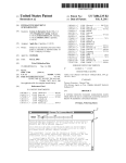
THE OL400/800/820/830/840 VIDEO TRAINING KIT covers the following
products:
o OL400
o OL800
o OL820
o OL830
o OL840
The following items are included in the kit:
o OL400 Service Handbook
o OL800/820 Service Handbook
o OL830 Service Handbook
o OL840 Service Handbook
o Service Training Video
o OL400/800/820 User's Documentation
o OL830 User's Documentation
o OL840 User's Documentation
Price: $95.00
($124.00 Canadian)
P/N 58226902
Copyright 1997, Okidata, Division of OKI America, Inc. All rights reserved. See the OKIDATA Business
Partner Exchange (BPX) for any updates to this material. (http://bpx.okidata.com)
Page: 4
Service Guide OL830
Chapter 1 Product Specifications
1.1 OVERVIEW
1.1.01 General Information
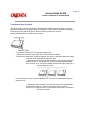
The OL830 is an 8 page per minute page printer, with Adobe Postscript capability. The OL830
uses a stationary LED head and dry electrophotography as its exposure and development
methods.
In addition to supporting Adobe Postscript (17 Fonts), the OL830 provides the HP LaserJet Series
II emulation, which has 36 resident fonts and the Diablo 630 emulation, which has 6 resident
fonts. The OL830 is shipped with the emulation board already installed.
An optional font card can be installed with either the PostScript or HP mode. Four cards are
available for use in PostScript Mode: Futura and More, Garamond and More, Optima and More,
and PostScript Essentials. Seven cards are available for use in the HP mode. Six of the seven
cards are available from Okidata: Barcodes Plus, Letter Gothic, MICRO DOCS, OKIPRO 65,
Prestige Elite, and Tax. The seventh card, the Custom Font Card, is available from Architext. The
OL830 also accepts downloadable fonts.
A 2 Mbyte page memory is standard on the OL830. This can be expanded to 4 Mbyte with an
optional RAM printed circuit board.
A Centronics parallel interface is standard. An optional interface board may be installed. This
board contains three interfaces: AppleTalk, RS232-C Serial, and RS422-A Serial.
Two consumables are used in the printer. The toner cartridge kit contains a toner cartridge, a
fuser cleaner pad, and an LED lens cleaner. The other consumable, the image drum cartridge kit,
includes an image drum cartridge and an ozone filter. Toner and drum life depend on printer use.
Based on a 5% print density and 10 pages per job, a toner cartridge should last approximately
2,500 pages; a drum should last approximately 15,000 pages.
A 200 sheet letter-size paper tray is included with the printer, and a second tray can be added, (if
the optional second paper feed unit is installed), providing an additional 200 pages. Legal,
Envelope, Executive and A4 paper trays are also available. Paper feeding can be done
automatically or manually. Pages can be printed face-down or face-up. The face-up stacker
assembly located at the back of the printer must be used for items such as card stock, envelopes,
labels or overhead transparencies.
The OL830 Printer is a member of the family of OL Series Printers which includes the OL400,
OL800, OL820, and OL840. Okidatas own proprietary engine assures built-in quality and
reliability.
Copyright 1997, Okidata, Division of OKI America, Inc. All rights reserved. See the OKIDATA Business
Partner Exchange (BPX) for any updates to this material. (http://bpx.okidata.com)
Page: 5
Service Guide OL830
Chapter 1 Product Specifications
1.2 PRINT SPECIFICATIONS
1.2.01 Print Specifications
Development method: Dry electrophotography
Exposure method: Stationary LED head
1.2.02 Print Speed
First print: 28 seconds maximum (letter size)
Continuous print: 8 sheets/minute (letter size)
Warm-up time: 50 seconds maximum [at room temperature 77 o F (25 o C) and rated voltage
(120 VAC)]
Postscript Initialization time: 120 seconds maximum [with 4 megabytes memory installed and "Do
Start Page" deselected]
1.2.03 Symbol Sets
HP Emulation
Thirty-nine symbol sets are available through the OL830.
1.2.04 Available Resident Fonts
PostScript
17 Adobe Fonts
HP Emulation
36 resident fonts and (HP A,B,C,F,L,Y,S1 and S2 Cartridge Fonts)
Diablo 630
6 resident fonts
1.2.05 Paper Feed Method
Automatic feed
Manual Feed
1.2.06 Paper Delivery Method
Face down
Face up
1.2.07 Print Resolution
300 x 300 dots/inch
NOTE:
The OL830 PostScript Mode produces only 300 x 300 dots/inch resolution.
150 x 150 dots/inch
100 x 100 dots/inch
75 x 75 dots/inch
1.2.08 Memory
RAM
Resident: 2 Mbyte
Optional: 2 Mbyte
ROM
Program: 1 Mbyte (Emulation PCB)
Resident: 512 Kbyte (Controller PCB)
1.2.09 Interfaces
Standard
Centronics Parallel
Options
One interface board which contains three interfaces
AppleTalk, RS232-C Serial, RS422-A Serial (uses AppleTalk connector)
1.2.10 Emulation Board
Provides the HP LaserJet II Emulation
Provides the Diablo 630 Emulation
Copyright 1997, Okidata, Division of OKI America, Inc. All rights reserved. See the OKIDATA Business
Partner Exchange (BPX) for any updates to this material. (http://bpx.okidata.com)
Page: 6
Service Guide OL830
Chapter 1 Product Specifications
1.3 PAPER SPECIFICATIONS
1.3.01 Paper Types
Letter
Size: 8.5" x 11"
Feed: Automatic or Manual
Weight: Minimum 16 lbs
Maximum 24 lbs
Recommended 20 lbs
Legal (option)
Size: 8.5" x 14"
Feed: Automatic (with optional paper tray) or Manual
Weight: Minimum 16 lbs
Maximum 24 lbs
Recommended 20 lbs
Executive (option)
Size: 7.25" x 10.5"
Feed: Automatic (with optional paper tray) or Manual
Weight: Minimum 16 lbs
Maximum 24 lbs
Recommended 20 lbs
A4 (option)
Size: 8.27" x 11.69" (210 mm x 297 mm)
Feed: Automatic (with optional paper tray) or Manual
Weight: Minimum 16 lbs
Maximum 24 lbs
Recommended 20 lbs
Envelopes (option)
Size: Minimum 3.5" x 7.5"
Maximum 7.2" x 10.1"
Feed: Automatic (with optional paper tray) or Manual
Weight: Minimum 16 lbs
Maximum 24 lbs
Recommended 20 lbs
Types
Business
4.12" x 9.5"
C5
6.4" x 9.12"
DL
4.36" x 8.77"
Monarch
3.87" x 7.5"
Labels
Manual feed
Face up delivery only
Use labels designed specifically for laser printers.
Transparencies
Manual feed
Face up delivery only
Must be able to withstand the heat (150° C) of the fusing process.
CAUTION:
Envelopes, labels, and transparencies should only be fed from the top paper tray.
Copyright 1997, Okidata, Division of OKI America, Inc. All rights reserved. See the OKIDATA Business
Partner Exchange (BPX) for any updates to this material. (http://bpx.okidata.com)
Page: 7
Service Guide OL830
Chapter 1 Product Specifications
1.4 PHYSICAL SPECIFICATIONS
1.4.01 Outside Dimensions
Width: 17.72"
Height: 6.02" (does not include optional second paper tray)
Length: 17.72" (does not include paper tray)
1.4.02 Printer Weight
24 lbs. (does not include options)
1.4.03 LED Array
Number of LED Elements - 2560
Copyright 1997, Okidata, Division of OKI America, Inc. All rights reserved. See the OKIDATA Business
Partner Exchange (BPX) for any updates to this material. (http://bpx.okidata.com)
Page: 8
Service Guide OL830
Chapter 1 Product Specifications
1.5 POWER REQUIREMENTS
1.5.01 Input Power
120 VAC +5.5%, -15%
220/240 VAC +/-10%
1.5.02 Power Consumption
Approximately 800 W maximum during operation
Approximately 22 W maximum during stand-by (fuser is off)
Copyright 1997, Okidata, Division of OKI America, Inc. All rights reserved. See the OKIDATA Business
Partner Exchange (BPX) for any updates to this material. (http://bpx.okidata.com)
Page: 9
Service Guide OL830
Chapter 1 Product Specifications
1.6 ENVIRONMENTAL CONDITIONS
1.6.01 Ambient Temperature and Relative Humidity
While operating:
50° to 90° F
10° to 32° C
20 to 80% Relative Humidity
While in storage:
-4° to 110° F
-20° to 43° C
10 to 90% Relative Humidity
1.6.02 Printer Noise Level
At standby: 43 decibels maximum
Copyright 1997, Okidata, Division of OKI America, Inc. All rights reserved. See the OKIDATA Business
Partner Exchange (BPX) for any updates to this material. (http://bpx.okidata.com)
Page: 10
Service Guide OL830
Chapter 1 Product Specifications
1.7 AGENCY APPROVALS
FCC Class B
UL 478 Version 5
CSA 22.2 220
Copyright 1997, Okidata, Division of OKI America, Inc. All rights reserved. See the OKIDATA Business
Partner Exchange (BPX) for any updates to this material. (http://bpx.okidata.com)
Page: 11
Service Guide OL830
Chapter 1 Product Specifications
1.8 CONSUMABLES
1.8.01 Toner Cartridge Kit
Toner Cartridge
Fuser Cleaner Pad
LED Lens Cleaning Pad
1.8.02 Image Drum Cartridge
Image Drum Cartridge
Ozone Filter
Copyright 1997, Okidata, Division of OKI America, Inc. All rights reserved. See the OKIDATA Business
Partner Exchange (BPX) for any updates to this material. (http://bpx.okidata.com)
Page: 12
Service Guide OL830
Chapter 1 Product Specifications
1.9 OPTIONS
1.9.01 RAM Expansion Board
2 Mbyte (expands printer memory to 4 Mbyte)
User installable
1.9.02 RS232C/AppleTalk/RS422 Interface Board
User installable
1.9.03 Font Cards
HP Emulation Mode
Available from Okidata
Barcodes Plus
Letter Gothic
MICRO DOCS
OKIPRO 65
Prestige Elite
Tax Fonts
Available from Architext
Custom Font Card
PostScript Mode
Futura and More
Garamond and More
Optima and More
PostScript Essentials
1.9.04 Paper Trays
A4
Envelope
Executive
Legal
Letter
1.9.05 Second Paper Feed Unit
Copyright 1997, Okidata, Division of OKI America, Inc. All rights reserved. See the OKIDATA Business
Partner Exchange (BPX) for any updates to this material. (http://bpx.okidata.com)
Page: 13
Service Guide OL830
Chapter 1 Product Specifications
1.10 RELIABILITY DATA
1.10.01 Printer Mean Page Between Failure (MPBF)
Approximately 32,000 pages
1.10.02 Printer Mean Time to Repair (MTTR)
Approximately 20 minutes
1.10.03 Estimated Printer Life
Approximately 360,000 pages
1.10.04 Estimated Fuser Life
Approximately 180,000 pages
1.10.05 Printer Duty Cycle
Approximately 5,000 pages per month @ 5% print density
Copyright 1997, Okidata, Division of OKI America, Inc. All rights reserved. See the OKIDATA Business
Partner Exchange (BPX) for any updates to this material. (http://bpx.okidata.com)
Page: 14
Service Guide OL830
Chapter 2 Principles of Operation
2.1 OVERVIEW
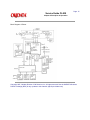
2.1.01 Outline of Printer Operation
The primary control boards of the printer are the Engine Controller Board (LLAB-2) and the Main
Controller Board (APSM). The Engine Controller Board controls the printer mechanism and drives
the LED head. The Main Controller Board receives data from the host device, analyzes
commands, and processes the data for printing.
The APSM PCB is connected to the host system through a Centronics parallel interface, RS-232C
serial interface or an AppleTalk/RS422 interface. Interface selection is accomplished through
menu settings. The Main Controller Board receives print data and command strings from the host
system, and generates bit image data. When one page of print data is ready, the Main Controller
Board turns on the PRINT-N signal which is one of the video interface signals. Upon receipt of the
PRINT-N signal, the Engine Controller Board turns ON the main motor, resist motor, and fuser in
preparation for printing. The Engine Controller Board then sends the FSYNC-N and LSYNC-N
signals to the Main Controller Board.
Once the Main Controller Board receives the FSYNC-N and LSYNC-N signals, the WDATA-N
signal (image data signal) is sent to the Engine Controller Board in synchronization with the
WCLK-N signal. The Engine Controller Board turns ON the appropriate LEDs in conformance with
the WDATA-N signal.
In addition to the above, the Engine Controller Board controls the paper feed, paper transport, and
electrostatic processing actions necessary for printing.
The Operation Panel is connected to the Main Controller Board via the LLCC PCB and the Engine
Controller Board. The Operation Panel is controlled by the Main Controller Board.
The Main Controller Board contains 2 Mbytes of dynamic RAM. The Expansion Memory Board
(REXM) provides an additional 2 Mbytes of dynamic RAM.
An optional font card can also be installed. Each font card contains ROM which provides
additional fonts. The font card connects directly to the Main Controller Board.
Copyright 1997, Okidata, Division of OKI America, Inc. All rights reserved. See the OKIDATA Business
Partner Exchange (BPX) for any updates to this material. (http://bpx.okidata.com)
Page: 15
Service Guide OL830
Chapter 2 Principles of Operation
Block Diagram of Printer
Copyright 1997, Okidata, Division of OKI America, Inc. All rights reserved. See the OKIDATA Business
Partner Exchange (BPX) for any updates to this material. (http://bpx.okidata.com)
Page: 16
Service Guide OL830
Chapter 2 Principles of Operation
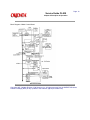
Block Diagram of Main Control Board
Copyright 1997, Okidata, Division of OKI America, Inc. All rights reserved. See the OKIDATA Business
Partner Exchange (BPX) for any updates to this material. (http://bpx.okidata.com)
Page: 17
Service Guide OL830
Chapter 2 Principles of Operation
2.2 PRINTER OVERVIEW
2.2.01 General Information
This section describes the operation of the OL830 Printer in the following order:
Main Control Function
Printer Control Function
Mechanical Operation
Sensors and Switches
Copyright 1997, Okidata, Division of OKI America, Inc. All rights reserved. See the OKIDATA Business
Partner Exchange (BPX) for any updates to this material. (http://bpx.okidata.com)
Page: 18
Service Guide OL830
Chapter 2 Principles of Operation
2.2.02 Main Control Unit
The control unit controls reception of the data from the host through the interface, processes
command analysis, bit image development, and raster buffer read. It also controls signal flow with
the Engine Controller Board and the Operator Panel.
Reception Control
The control unit has three interface ports: centronics parallel and optional RS-232C serial, and
Appletalk/RS-422 serial ports. Through the menu, one of the I/F ports can be selected at a time.
The other ports output BUSY in emulation mode, but not in PostScript mode. The Centronics
Parallel port is the default port for the OL830.
Command Analysis Processing
The OL830 contains the PostScript Interpreter and the following emulation modes (which are
selected through the printer MENU.)
LaserJet Series II: Hewlett Packard
Diablo 630 : Xerox
In the PostScript mode, each typeface style is stored as a series of outlines, one for each
character, comprised of lines and Bezier curves. The shape of each character in a typeface style
is actually determined by a mathematical formula. When the document is to be printed, the host
sends information to the printer in the form of the PostScript page description language. The
printer then reads the file it receives, sizes and orients each character outline as required, and
prints the page.
In the HP and Diablo modes, the OL830 prints fonts as bit-mapped outlines. The outline of each
character is determined by placing dots in a grid. A complete set of these grids, one for each
character in the font, is stored in ROM. Since no special calculations are used in the HP mode,
each typeface, style, weight, orientation and size is stored separately.
Down-line-loaded (DLL) fonts and macro registration are stored in the DLL and macro areas of
memory (RAM). Emulation and PostScript interpretation are performed under program control by
the CPU.
Font Processing
In the emulation mode, the bit image in the font ROM is loaded by the CPU into the raster buffer
(RAM). The raster buffer has a band buffer structure; new data is written to the raster buffer once
the buffer has been read and becomes empty.
In PostScript mode, the outline data stored in the programmed ROM is loaded into the RAM area
called the font cache. The required font pattern is then transferred to the raster buffer. The buffer
has a full-page buffer structure. One page of data is written at a time. After a page is written,
another raster buffer read operation starts.
Raster Buffer Read Operation
The bit image written to the raster buffer by the CPU is converted to serial dot data to be read in
response to the VIDEO SYNCH signal.
The first-in, first-out (FIFO) buffer is between the raster buffer and the serial dot data of the video
interface (WDATA).
The CPU can transfer data from the raster buffer to the FIFO automatically when the CPU reads
the "OR-ING" memory area of the raster buffer. The CPU reads a line of data from the raster
buffer before the LSYNC signal is received from the Engine Controller Board.
Once LSYNC is received, reading starts. Then, in response to WCLK, parallel to serial conversion
and data transfer take place.
The amount of data that is read from the FIFO is sensed by the 64NC22VIA counter. The CPU
writes another line of data to the FIFO, immediately after a line of data is read from the FIFO.
Engine I/F Processing
The engine I/F is divided into the engine control signal and the command interface. The engine
control signal is allocated to a signal line through bits of the TTL register. The CPU can obtain the
engine status by sensing each bit, or run the engine by manipulating each bit.
The command I/F is a bidirectional serial signal. The TTL register is used for serial-parallel or
parallel-serial conversion.
Operation Panel Control
The operation panel I/F is a bidirectional serial signal. Each signal line is allocated to the IOA port.
The CPU then sends the shift clock and executes serial or serial-parallel conversion.
Copyright 1997, Okidata, Division of OKI America, Inc. All rights reserved. See the OKIDATA Business
Partner Exchange (BPX) for any updates to this material. (http://bpx.okidata.com)
Page: 19
Service Guide OL830
Chapter 2 Principles of Operation
2.2.03 Main Controller Board (APSM)
The Main Controller Board (APSM) consists of the CPU, RAM, ROM, Serial Communications
Controller (SCC), FIFO, EEPROM and Gate Array.
The CPU is a MC68000 with a clock frequency of 12.5MHz.
Sixteen 1 Mbit (1 bit x 1 Mbit) dynamic RAM chips are mounted as resident RAM (total 2Mbytes).
Two 4 Mbit EPROMs store program data for PostScript operation. Two 4 Mbit EPROMs are
located on the optional emulation PCB.
The IOA (Input/Output Adapter) IC12 (MSM75V036) controls the Operation Panel interface,
Printer Unit interface, read/write operations of FIFO (IC13) and the EEPROM IC1 (X2404).
The FIFO (First in-First out Buffer) connects the CPU to the video interface. The FIFO has a
capacity of over 2 lines (2 rasters). The data written to the FIFO by the CPU is sequentially read
according to the VIDEO I/F synchronous signal.
The Serial Communications Controller - SCC - (Z8530H8) controls the RS-232C interface,
RS-422 interface, and the AppleTalk interface. The RS-422 and AppleTalk interfaces use the
same connector. Although the RS-422 and AppleTalk interfaces are physically the same, they use
different protocols and are usable only in the PostScript mode.
Copyright 1997, Okidata, Division of OKI America, Inc. All rights reserved. See the OKIDATA Business
Partner Exchange (BPX) for any updates to this material. (http://bpx.okidata.com)
Page: 20
Service Guide OL830
Chapter 2 Principles of Operation
2.2.04 Emulation Board (APSH)
The Emulation Board (APSH) is connected to the Main Controller Board. The APSH board
consists of:
Two 1 Mbit EPROM for Emulation Mode
Two 4 Mbit MASK ROMs which store the bit-map fonts used in HP Laserjet and Diablo
emulations
One TTL IC, which function as an address decoder.
Copyright 1997, Okidata, Division of OKI America, Inc. All rights reserved. See the OKIDATA Business
Partner Exchange (BPX) for any updates to this material. (http://bpx.okidata.com)
Page: 21
Service Guide OL830
Chapter 2 Principles of Operation
2.2.05 Expansion RAM Board (REXM)
Sixteen 1Mbit (1bit x 1Mbit) dynamic RAM (total 2 Mbytes) are mounted to the Expansion RAM
Board. The RAM capacity is detected during the power-on sequence. The RAM capacity is printed
during MENU PRINT in the Emulation Mode or START PAGE in Postscript mode.
Copyright 1997, Okidata, Division of OKI America, Inc. All rights reserved. See the OKIDATA Business
Partner Exchange (BPX) for any updates to this material. (http://bpx.okidata.com)
Page: 22
Service Guide OL830
Chapter 2 Principles of Operation
2.2.06 Font Card
An optional font card for additional fonts can be installed. If the printer is in the off-line state (the
READY lamp is off), the card can be inserted and removed without removing power. When the
font card is inserted and removed in the on-line state (the READY lamp is on), the message,
CARD REMOVED ONLINE, will be displayed on the Operation Panel.
Copyright 1997, Okidata, Division of OKI America, Inc. All rights reserved. See the OKIDATA Business
Partner Exchange (BPX) for any updates to this material. (http://bpx.okidata.com)
Page: 23
Service Guide OL830
Chapter 2 Principles of Operation
2.3 PRINTER CONTROL UNIT
2.3.01 General Information
Below are the principal hardware components of the printer control unit.
Engine Board
Power Supply Unit
Fuser Unit
Main Motor
LED Head
Sensors and Switches
Resist Motor
Fan
Operation Panel
Copyright 1997, Okidata, Division of OKI America, Inc. All rights reserved. See the OKIDATA Business
Partner Exchange (BPX) for any updates to this material. (http://bpx.okidata.com)
Page: 24
Service Guide OL830
Chapter 2 Principles of Operation
2.3.02 Engine Controller Board (LLAB-2)
The Engine Controller Board contains an 80C51 Microprocessor (8-bit), an EPROM which stores
the Engine Control Program and an EEPROM.
The Engine Controller Board turns the LED array diodes ON to place an electrostatic image on
the photosensitive drum. The Engine Controller Board also controls the paper feed, paper
transport, and electrophotographic processing actions so the electrostatic image can be printed by
fusing toner on the paper.
The 1 Kbit Electrically Erasable PROM (EEPROM) is loaded with the following data:
Total number of sheets printed after installation
Modified page count
Total number of sheets printed with the current drum
Total number of sheets printed with the current fuser
Setting of time required from the completion of printing to Quiet Mode
Feed time needed to feed the paper to a printable position
Vertical Registration (Top margin)
LED head drive time.
NOTE:
The EEPROM preserves the data while the supply voltage is off.
The counters stored in the EEPROM can be accessed by using SW1 on the Engine Controller
Board to set the printer in the Maintenance Mode. (See Section 3 of the OL400 Service
Handbook){ }
The count of the total number of sheets printed after installation cannot be reset.
The count of the total number of sheets printed with the drum currently in use should be taken as
a rough measure of the useful life of the drum: It is reset to zero when the drum is replaced by
holding down the RESET button and applying power to the printer.
Copyright 1997, Okidata, Division of OKI America, Inc. All rights reserved. See the OKIDATA Business
Partner Exchange (BPX) for any updates to this material. (http://bpx.okidata.com)
Page: 25
Service Guide OL830
Chapter 2 Principles of Operation
Block Diagram of Printer Unit
Copyright 1997, Okidata, Division of OKI America, Inc. All rights reserved. See the OKIDATA Business
Partner Exchange (BPX) for any updates to this material. (http://bpx.okidata.com)
Page: 26
Service Guide OL830
Chapter 2 Principles of Operation
2.3.03 Power Supply Unit
The power supply unit generates the following voltages from the AC input voltage:
High Voltage Drive
The high voltage circuit provides the charge voltage (about -6 Kvdc), transfer voltage (about +5
Kvdc), grid voltage (about -600vdc), and developer bias voltages (about -550vdc and -400vdc). Of
these voltages, the charge voltage and the transfer voltage are generated by a high-voltage power
supply. The grid connects to ground via a varistor on the medium-voltage generation circuit. This
keeps the grid at about -680vdc during charging.
Low Voltage Circuit
This circuitry produces the following voltages:
+5 vdc: Printer Logic
+/- 12 vdc: Interface Signal Levels
+38 vdc: Resist/Main Motor Drive, Fan Drive
Copyright 1997, Okidata, Division of OKI America, Inc. All rights reserved. See the OKIDATA Business
Partner Exchange (BPX) for any updates to this material. (http://bpx.okidata.com)
Page: 27
Service Guide OL830
Chapter 2 Principles of Operation
2.3.04 Fuser Unit
The Fuser Unit is controlled by a thermistor, a comparator, an LSI, and the CPU to keep the heat
roller surface temperature within a predetermined range (about 150 degrees Celsius). A thermal
fuse within the Fuser Unit prevents abnormal temperature rises in case the thermistor fails.
NOTE:
The CPU checks for an open circuit in the thermistor at POWER -ON, setting a fuser alarm if this
error is detected.
The CPU also sets a fuser alarm if the proper temperature is not attained within a specified period
of time after POWER-ON.
Upon detecting a fuser alarm, the CPU will halt (after printing the current page.)
Copyright 1997, Okidata, Division of OKI America, Inc. All rights reserved. See the OKIDATA Business
Partner Exchange (BPX) for any updates to this material. (http://bpx.okidata.com)
Page: 28
Service Guide OL830
Chapter 2 Principles of Operation
2.3.05 Main Motor (Drum Motor)
The Main Motor is controlled by the motor control LSIs, IC5 (M54646) and IC8 (M54646). The
motor used is a four-phase motor, driven by the DM-PHL 1, 2, 3 and 4 signals generated by the
LSI.
Copyright 1997, Okidata, Division of OKI America, Inc. All rights reserved. See the OKIDATA Business
Partner Exchange (BPX) for any updates to this material. (http://bpx.okidata.com)
Page: 29
Service Guide OL830
Chapter 2 Principles of Operation
2.3.06 LED Array
Data for the 2,560 LEDs in the LED Array is placed in the shift register by the HD CLK signal. The
data is loaded in the latch circuit by the HD LD signal.
Copyright 1997, Okidata, Division of OKI America, Inc. All rights reserved. See the OKIDATA Business
Partner Exchange (BPX) for any updates to this material. (http://bpx.okidata.com)
Page: 30
Service Guide OL830
Chapter 2 Principles of Operation
2.3.07 Resist Motor
The Resist Motor is driven clockwise for hopping, then counterclockwise for Paper Feeding by the
motor drive IC (LB1731).
Copyright 1997, Okidata, Division of OKI America, Inc. All rights reserved. See the OKIDATA Business
Partner Exchange (BPX) for any updates to this material. (http://bpx.okidata.com)
Page: 31
Service Guide OL830
Chapter 2 Principles of Operation
2.3.08 DC Fan
The fan is controlled by the FAN ON-P signal from the LSI (MSM73H019). In order for the printer
to operate, the signal FAN SENSE-N must be active.
NOTE:
The fuser and the fan are not enabled when the cover is open. If the fan fails to run, the fuser will
turn off and FAN ALARM is set. Printing is disabled.
In accordance with the TIME TO QUIET setting of the Level 2 Menu, the Fuser will maintain the
proper fusing temperature for 1 or 8 minutes after the last page has been printed. If printing is not
requested within the selected time frame, the fuser will turn OFF and the fan speed will be
reduced 50%. Selecting DISABLE allows the FUSER to maintain the proper fusing temperature
continuously.
Copyright 1997, Okidata, Division of OKI America, Inc. All rights reserved. See the OKIDATA Business
Partner Exchange (BPX) for any updates to this material. (http://bpx.okidata.com)
Page: 32
Service Guide OL830
Chapter 2 Principles of Operation
2.3.09 Operation Panel
The following components make up the operation panel:
4-bit MPU (LC6543C)
LCD control driver (MSM6222B or HD44780)
LCD display (16 characters per line)
Operation panel sheet
LEDs (for Online Mode indication)
Operation Buttons
The Operation Panel is connected to the Main Controller Board via the Engine Connection Board
and the Engine Controller Board.
The LCD control driver (MSM622B or HD44780) converts 4-bit character codes received from the
MPU into 8-bit character codes and retrieves the character pattern data (font) from the internal
character generator for display on the LCD.
Copyright 1997, Okidata, Division of OKI America, Inc. All rights reserved. See the OKIDATA Business
Partner Exchange (BPX) for any updates to this material. (http://bpx.okidata.com)
Page: 33
Service Guide OL830
Chapter 2 Principles of Operation
2.3.10 Sensor Functions
Power On
The inlet and outlet sensors are checked for their on and off states at POWER ON time.
Inlet sensor on: Inlet jam error (paper supply jam)
Outlet sensor on: Outlet jam error (paper eject jam)
The thermistor sensor detects if the fuser temperature reaches the desired temperature within the
specified time. If the desired temperature is not reached, the fuser is turned OFF.
The fan sensor circuitry checks for the rotation of the fan. If fan motion is not detected, the fuser is
turned OFF, and power is removed from the fan.
When an empty paper cassette has been detected, the Paper-End Sensor sends the PAPER
END signal to the Control Unit.
When the power supply is turned ON, the number of printed pages of the fusing unit and drum
cartridge is checked. If the Fuser or Drum life has been exceeded, this information is transmitted
to the Control Unit.
Hopping
Whenever the inlet sensor fails to detect paper within a predetermined time after a feed command
has been issued to the paper supply system, the failure is counted. The hopping operation is then
attempted up to three times. If the hopping operation still fails, an INLET JAM ERROR is displayed
on the Operation Panel.
Feeding
If the leading part of the paper does not reach the outlet sensor within a predetermined time after
the start of feeding by the resist motor, a FEED JAM ERROR will be displayed on the Operation
Panel.
Copyright 1997, Okidata, Division of OKI America, Inc. All rights reserved. See the OKIDATA Business
Partner Exchange (BPX) for any updates to this material. (http://bpx.okidata.com)
Page: 34
Service Guide OL830
Chapter 3 Maintenance & Disassembly
3.1 MAINTENANCE
3.1.01 General Information
This section lists the parts replacement, adjustment, cleaning, and lubrication procedures.
Disassembly should not be performed unless absolutely necessary. NEVER perform disassembly
on a malfunctioning unit until you have followed the failure analysis procedures in Section Four of
this Service Handbook.
Follow the procedures listed in Adjustments and Service Settings. Adjustments may be required
when either consumables or parts are replaced. Failure to perform these procedures could result
in unnecessary service calls.
Cleaning procedures must be performed correctly if high print quality is to be achieved.
Copyright 1997, Okidata, Division of OKI America, Inc. All rights reserved. See the OKIDATA Business
Partner Exchange (BPX) for any updates to this material. (http://bpx.okidata.com)
Page: 35
Service Guide OL830
Chapter 3 Maintenance & Disassembly
3.1.02 Maintenance Tools
The following tools are required to service the unit.
#2 Phillips Screwdriver (with magnetic tip)
Straight-slot Screwdriver
Needle Nose Pliers (4 Inch)
Digital Multimeter
Shop Vacuum (with filter for toner)
Cloth (soft and lint-free)
All-purpose Cleaner
Grease (Dow Corning BR2 or equivalent)
Copyright 1997, Okidata, Division of OKI America, Inc. All rights reserved. See the OKIDATA Business
Partner Exchange (BPX) for any updates to this material. (http://bpx.okidata.com)
Page: 36
Service Guide OL830
Chapter 3 Maintenance & Disassembly
3.1.03 Maintenance Precautions
DO NOT disassemble the unit if it is operating normally.
Before starting disassembly and assembly, always power OFF the unit and detach the power cord.
Detach the interface cable, if installed.
Do not remove parts unnecessarily. Try to keep disassembly to a minimum.
Use the recommended maintenance tools.
When disassembling, follow the listed sequence. Failure to follow the correct sequence may result in
damaged parts.
Screws, collars and other small parts are easily lost. Temporarily attach these parts to their original
positions.
When handling circuit boards use extreme care. Integrated circuits (microprocessors, ROM, and RAM)
can be destroyed by static electricity.
Do not place printed circuit boards directly on conductive surfaces.
Follow the recommended procedures when replacing assemblies and units.
Clear the drum counter when a new drum cartridge is installed.
1. Power OFF the unit.
2. Press and hold RESET while powering ON the unit.
3. The drum counter will reset.
Clear the fuser counter when a new fusing unit is installed. Refer to Section 3.3{
Service Handbook.
}, Adjustments in this
Copyright 1997, Okidata, Division of OKI America, Inc. All rights reserved. See the OKIDATA Business
Partner Exchange (BPX) for any updates to this material. (http://bpx.okidata.com)
Page: 37
Service Guide OL830
Chapter 3 Maintenance & Disassembly
3.2 DISASSEMBLY/ASSEMBLY PROCEDURES
General Information
This section contains the printer disassembly procedures. Only the removal procedures are
explained. Reverse the procedure for the installation.
This Service Handbook lists the disassembly procedures for major components of the unit.
Okidata does NOT recommend disassembling a unit which is operating normally. If you decide to
perform disassembly during this training, Okidata recommends that you perform only the
disassembly procedures for RSPL items. All other procedures are provided to assist you in
identifying parts. It is not likely that you will perform these procedures while servicing the product.
Read all notes, cautions, and warnings. They contain important information regarding
assembly/disassembly.
Copyright 1997, Okidata, Division of OKI America, Inc. All rights reserved. See the OKIDATA Business
Partner Exchange (BPX) for any updates to this material. (http://bpx.okidata.com)
Page: 38
Service Guide OL830
Chapter 3 Maintenance & Disassembly
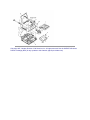
Sequence of Procedures
NOTE:
The procedures listed in this manual are for the OL830 Upper Cover, the Optional Interface Board
(APSR), the Optional RAM Board (REXM), the Emulation Board (APSH), and the Main Controller
Board (APSM).
Refer to the OL400 Service Handbook for the remaining procedures{ }.
The printer will be disassembled in the order listed below.
1. Upper Cover
2. LED Head
3. AppleTalk/Serial Interface Board (option)
4. RAM Board (option) (REXM)
5. Emulation Board (APSH)
6. Main Controller Board with parallel interface (APSM)
7. Engine Controller Board (LLAB-2)
8. Main Motor Assembly
9. DC Fan Assembly
10. Idle Gears "A" and "B", and the Reduction Gear
11. Power Supply Unit
12. Upper Unit
13. Fusing Unit
14. Backup Roller
15. Transfer Charger Assembly
16. Resist Roller Assembly
17. Idle Gear C
18. Paper Supply Unit
19. Resist Motor
20. Engine Connection Board
21. Ozone Filter
Copyright 1997, Okidata, Division of OKI America, Inc. All rights reserved. See the OKIDATA Business
Partner Exchange (BPX) for any updates to this material. (http://bpx.okidata.com)
Page: 39
Service Guide OL830
Chapter 3 Maintenance & Disassembly
Board Layout
Copyright 1997, Okidata, Division of OKI America, Inc. All rights reserved. See the OKIDATA Business
Partner Exchange (BPX) for any updates to this material. (http://bpx.okidata.com)
Page: 40
Service Guide OL830
Chapter 3 Maintenance & Disassembly
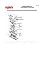
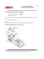
3.2.01 Upper Cover
on
1. Power OFF the printer and unplug the AC power cord from the outlet.
2. Remove the paper cassette (1), interface cable (2), and font card (option) (3).
3. Lift the operator panel assembly (4) at its bottom and remove it.
4. Remove connecting cable (5) from the connector J1 (6) of the LLJA Board (7).
5. Press the "OPEN" button (8) and open the stacker cover (9).
6. Remove the two screws (10).
7. Lift the front side of the upper cover, and disconnect its engagement with the two tabs
the rear of the lower unit (11), by pivoting the upper cover upward and back.
P/N 53338201 OL830 Upper Cover
NOTES:
When installing the upper cover, first set the square holes on the back of the upper cover
over the two tabs on the rear of the lower unit , then lower the cover.
Option Cover
The Emulation Board (APSH) which adds Hewlett-Packard Laser Jet II ,and Diablo emulation, is a
standard feature and is present in the printer when shipped. The optional RAM (REXM) and
Interface (APSR) Boards, are operator installable by removing the Option Cover (A). To remove
the Option Cover, first make sure the printer is turned off and unplugged, then press the release
button (B) and open the top cover (C). Remove the Option Cover by pulling up gently on its inside
edge. Close the top cover, then install the boards. Remember, the components on the boards are
sensitive to static electricity--handle them carefully.
Copyright 1997, Okidata, Division of OKI America, Inc. All rights reserved. See the OKIDATA Business
Partner Exchange (BPX) for any updates to this material. (http://bpx.okidata.com)
Page: 41
Service Guide OL830
Chapter 3 Maintenance & Disassembly
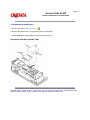
3.2.02 AppleTalk/Serial Interface Board (APSR) (Option)
1. Remove the upper cover. (See 3.2.01){
}
2. Remove the two screws (1).
3. Pull outward slightly on the two flanges (2) on shield plate B (3), releasing the two small
tabs (4).
4. Lift out the interface board.
NOTE:
When installing the interface board, make sure that the board is under the tabs (4).
P/N 55058001 OL830 AppleTalk/Serial Interface Board
Copyright 1997, Okidata, Division of OKI America, Inc. All rights reserved. See the OKIDATA Business
Partner Exchange (BPX) for any updates to this material. (http://bpx.okidata.com)
Page: 42
Service Guide OL830
Chapter 3 Maintenance & Disassembly
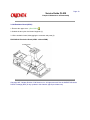
3.2.03 RAM Board (REXM) Option
1. Remove the upper cover. (See 3.2.01){
}
2. Remove the shield cover (1) by squeezing sides (2) then lifting.
3. Lift the RAM board, disengaging the connectors and posts (3).
P/N 55051601 RAM Board (REXM) (2 MB)
Copyright 1997, Okidata, Division of OKI America, Inc. All rights reserved. See the OKIDATA Business
Partner Exchange (BPX) for any updates to this material. (http://bpx.okidata.com)
Page: 43
Service Guide OL830
Chapter 3 Maintenance & Disassembly
3.2.04 Emulation Board (APSH)
1. Remove the upper cover. (See 3.2.01){
}
2. Unlatch the two nylon circuit board supports (1).
3. Lift the emulation board, disengaging the connector and posts (2).
P/N 55058101 Emulation Board (APSH - without ROM)
Copyright 1997, Okidata, Division of OKI America, Inc. All rights reserved. See the OKIDATA Business
Partner Exchange (BPX) for any updates to this material. (http://bpx.okidata.com)
Page: 44
Service Guide OL830
Chapter 3 Maintenance & Disassembly
3.2.05 Main Controller Board (APSM)
1. Remove the upper cover. (See 3.2.01){
}
2. Remove the interface board (APSR) if installed. (See 3.2.02){
3. Remove the RAM board (REXM) if installed. (See 3.2.03){
4. Remove the emulation board (APSH) (See 3.2.04){
}
}
}
5. Remove the four screws (1) and remove shield plate B (2).
6. Remove the four screws (3),
7. Lift the main controller board, disengaging it from the connector (4).
P/N 55057901 Main Controller without ROM (APSM)
Copyright 1997, Okidata, Division of OKI America, Inc. All rights reserved. See the OKIDATA Business
Partner Exchange (BPX) for any updates to this material. (http://bpx.okidata.com)
Page: 45
Service Guide OL830
Chapter 3 Maintenance & Disassembly
3.2.06 Second Paper Feed Unit
The Second Paper Feed Unit doubles the OL830s paper handling capacity by adding a second
paper feed mechanism. The paper tray is sold separately. Here are the procedures for adding the
Second Paper Feed Unit to the printer. Reverse these procedures for removal.
Before installation/removal, perform this procedure.
1. Set power switch to OFF and unplug the power cord.
2. Remove the interface cable, paper tray, and font cards, if installed.
3. Remove the image drum and toner cartridge. Put them in a safe place where the image
drum will not be scratched or exposed to light.
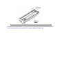
1. Remove the connector cover from the bottom of the printer using a flat
blade screwdriver. This will expose an edge connector. Do not discard
the connector cover. It must be installed if the Second Paper Feed Unit is
removed from the printer.
It is not necessary to turn the printer upside down. The printer is shown upside down for
illustration only.
2. Unpack the Second Paper Feed Unit. Notice the two metal guide pins
and the black connector. The two metal guide pins are used for
alignment. The edge connector, on the bottom of the printer, will attach to
the black connector.
3. Set the printer next to the Second Paper Feed Unit with fronts facing the same direction.
4. Place the printer on the Second Paper Feed Unit aligning the corners of the printer to those of
the Second Paper Feed Unit.
5. Lower the printer onto the Second Paper Feed Unit. The metal guide pins will help make
alignment easier.
6. To activate the Second Paper Feed Unit, the TRAY SWITCH option in the Printer Menu must
be set to ON. ( See the Printer Handbook, Chapter 3--Controlling Your Printer.)
Copyright 1997, Okidata, Division of OKI America, Inc. All rights reserved. See the OKIDATA Business
Partner Exchange (BPX) for any updates to this material. (http://bpx.okidata.com)
Page: 46
Service Guide OL830
Chapter 3 Maintenance & Disassembly
3.3 ADJUSTMENTS AND SERVICE CHECKS
The first five adjustments (Actual Page Count, Modified Page Count, Vertical Print Start Position,
LED Head Drive Time and Resetting the Fuser Counter) are performed by changing addresses on
the EEPROM located on the engine controller printed circuit board.
Before performing these adjustments, setup the printer as listed below.
1. Raise the upper unit.
2. Remove the image drum cartridge.
3. Override the cover open interlock switch.
Copyright 1997, Okidata, Division of OKI America, Inc. All rights reserved. See the OKIDATA Business
Partner Exchange (BPX) for any updates to this material. (http://bpx.okidata.com)
Page: 47
Service Guide OL830
Chapter 3 Maintenance & Disassembly
3.3.01 Actual Page Count
The actual page counter counts the number of sheets printed by the printer. The value of the
actual page counter will be displayed as listed below.
1. Power ON the printer while pressing Switch 1 on the engine controller board. The LED (located on the
engine controller board) will flash once - then pause (the LED will continuously flash once - then
pause) indicating that the printer is in Parameter 1 of the maintenance mode.
2. Press Switch 1 for five seconds. The LED will display the contents of the Parameter 1 register (Actual
Page Counter) as listed below.
The long flash indicates start of count.
Short flashes indicate counter contents (most significant digit first).
(There will be a pause between digits)
Upon completion of the count, a long flash will indicate start of count. This process will loop until you
press Switch 1 for five seconds (this will cause the modified page count to be displayed (refer to
3.3.02){ }
Example
Actual Page Counter = 235 pages
Switch 1 Action
LED Display
Description
Press at Power
ON
Flashes ON/OFF
Parameter #1 Selected
Press for five
seconds
Long Flash
Start of Count
None
On-Off-On-Pause
1st Digit = 2
None
On-Off-On-Off-On-Pause
2nd Digit = 3
None
On-Off-On-Off-On-Off-On
-Off-On-Pause<P11.5M>
3rd Digit = 5
None
Long Flash
Start of Count
Press for five
seconds
Long Flash
Start of Modified Page
Count
NOTE:
The number "0" is represented by 10 flashes
Copyright 1997, Okidata, Division of OKI America, Inc. All rights reserved. See the OKIDATA Business
Partner Exchange (BPX) for any updates to this material. (http://bpx.okidata.com)
Page: 48
Service Guide OL830
Chapter 3 Maintenance & Disassembly
3.3.02 Modified Page Count
The modified page counter combines the main motor revolution time and the number of printed
sheets. Drum replacement is determined by the modified page count. Follow these steps to check
the modified page count.
NOTE:
To access the Modified Page Count, you must first view the Actual Page Count.
1. After viewing the Actual Page Count, press Switch 1 for five seconds. The LED will display the
contents of the Parameter 1 (Modified Page Count) register.
2. To end this procedure, press Switch 1 for one second. The LED will perform one short flash to
indicate Parameter 1 is selected.
Example
Modified Page Counter = 142
Switch 1 Action
LED Display
Description
Press for five
seconds
Long Flash
Start of Modified Page
Count
None
On-Off-Pause
1st Digit = 1
None
On-Off-On-Off-On-Off-On
-Pause
2nd Digit = 4
None
On-Off-On-Off-Pause
3rd Digit = 2
None
Long Flash
Start of Count
Press for 1
second
Flashes ON/OFF
Parameter #1 Selected
NOTE:
The number "0" is represented by 10 flashes
The Actual and Modified Page Counters cannot be changed.
Copyright 1997, Okidata, Division of OKI America, Inc. All rights reserved. See the OKIDATA Business
Partner Exchange (BPX) for any updates to this material. (http://bpx.okidata.com)
Page: 49
Service Guide OL830
Chapter 3 Maintenance & Disassembly
3.3.03 Vertical Print Start Position Adjustment
The Vertical Print Start Position Adjustment is used to set the top of form position. Use this
adjustment to correct print start variations between different OL printers, or to achieve 4.6 mm
vertical start position, the default value.
A chart of the EEPROM addresses and print start positions is shown below.
The Vertical Print Start Position is Parameter 9. To change the Vertical Print Start Position:
1. Power ON the printer while pressing Switch 1 on the Engine Control board. The LED
will
flash continuously, indicating that the printer is in Parameter 1 of the
maintenance mode.
2. Press Switch 1 eight times to access Parameter 9. The LED will flash nine times,
indicating Parameter 9 has been selected.
3. Press Switch 1 once for five seconds. The contents of the Parameter 9 register will be
displayed.
step
4. To modify the contents of the Parameter 9 register, press Switch 1 (momentarily) to
through the addresses (in accordance with the chart shown below).
To end the adjustment, press Switch 1 once for five seconds. The LED will flash nine times,
indicating Parameter 9.
NOTE:
Ten flashes represent the number zero.
On the table below, Address 0 comes after Address 15
EEPROM Address
Print Start
Position
EEPROM Address
Print Start
Position
0 DEFAULT
0 (mm)
8
-4.0 (mm)
1
+.5
9
-3.5
2
+1.0
10
-3.0
3
+1.5
11
-2.5
4
+2.0
12
-2.0
5
+2.5
13
-1.5
6
+3.0
14
-1.0
7
+3.5
15
-0.5
Copyright 1997, Okidata, Division of OKI America, Inc. All rights reserved. See the OKIDATA Business
Partner Exchange (BPX) for any updates to this material. (http://bpx.okidata.com)
Page: 50
Service Guide OL830
Chapter 3 Maintenance & Disassembly
3.3.04 Setting the LED Head Drive Time
This adjustment is necessary only when replacing the LED head. However, if the luminous energy
ratings of the new and original LED heads are the same, adjustment is not necessary. The
luminous energy rating is on the label on the LED head. Digits three and two, reading from the
right, are the drive time rating.
The LED Head Drive Time is Parameter 13. To change the LED Head Drive Time:
1. Power ON the printer while pressing Switch 1 on the Engine Control board. The LED
will
flash continuously, indicating that the printer is in Parameter 1 of the
maintenance mode.
2. Press Switch 1, twelve times to access Parameter 13. The LED will flash thirteen times,
indicating Parameter 13 has been selected.
3. Press Switch 1 once for five seconds. The contents of the Parameter 13 register will be
displayed.
4. To modify the contents of the Parameter 13 register, press Switch 1 (momentarily) to
step through the addresses (in accordance with the chart shown below).
To end the adjustment, press Switch 1 once for five seconds. The LED will flash thirteen
times, indicating Parameter 13. To end the adjustment, press Switch 1 once for five
seconds. Parameter 13 will be displayed.
Drive Time Rating displayed on
LED Head
Drive Time Setting Value
(Address)
08
5
09
4
10
3
11 12
2
13 14
1
15 16 17
0
18 19 20
15
21 22 23 24
14
25 26 27 28 29
13
30 31 32 33 34 35 36
12
Copyright 1997, Okidata, Division of OKI America, Inc. All rights reserved. See the OKIDATA Business
Partner Exchange (BPX) for any updates to this material. (http://bpx.okidata.com)
Page: 51
Service Guide OL830
Chapter 3 Maintenance & Disassembly
3.3.05 Resetting the Fuser Counter
After replacing the Fuser Unit, reset the fuser counter. Follow the procedure listed below.
1. Power ON the printer while pressing Switch 1 on the Engine Control board. The LED
will
flash continuously, indicating that the printer is in Parameter 1 of the
maintenance mode.
The Fuser Counter value is found in Parameter 3.
2. Press Switch 1 two times to access Parameter 3. The LED will flash three times,
indicating Parameter 3 has been selected.
3. Press Switch 1 once for five seconds. The contents of the Parameter 3 register will be
displayed.
4. Press Switch 1 once for five seconds to reset the fuser counter to zero.
5. To end the adjustment, press Switch 1 once for five seconds. The LED will flash three
times, indicating Parameter 3.
Copyright 1997, Okidata, Division of OKI America, Inc. All rights reserved. See the OKIDATA Business
Partner Exchange (BPX) for any updates to this material. (http://bpx.okidata.com)
Page: 52
Service Guide OL830
Chapter 3 Maintenance & Disassembly
3.3.06 DC Voltage Adjustment (+5vdc)
1. Use a digital voltmeter which has an input impedance of 10M Ohms and is capable of
displaying to the second decimal place or greater.
2. Check the voltage at CN1 of the interconnect board (1) between Pin 31, +5vdc and Pin 27,
ground. The value should be +5.1vdc (+/-0.1vdc)
3. Change the output voltage by adjusting potentiometer RV3 on the power supply board.
Copyright 1997, Okidata, Division of OKI America, Inc. All rights reserved. See the OKIDATA Business
Partner Exchange (BPX) for any updates to this material. (http://bpx.okidata.com)
Page: 53
Service Guide OL830
Chapter 3 Maintenance & Disassembly
3.4 CLEANING
3.4.01 General Information
Remove any dropped toner and dust. Clean inside and around the printer with a vacuum cleaner
(designed to pick-up toner) when necessary.
CAUTION:
Do not touch the image drum, the LED lens array, or the LED head connector block.
Copyright 1997, Okidata, Division of OKI America, Inc. All rights reserved. See the OKIDATA Business
Partner Exchange (BPX) for any updates to this material. (http://bpx.okidata.com)
Page: 54
Service Guide OL830
Chapter 3 Maintenance & Disassembly
3.4.02 Static Charger
Clean the static charger wire when black lines or stripes and toner blotching are present on the
paper or whenever replacing the image drum or toner cartridge.
1. Turn OFF the power supply switch, and press the "OPEN" button, which is on the top right of
the printer, and raise the stacker cover.
2. Lift the LED assembly. Locate the wire cleaner tab on the image drum cartridge.
3. Clean the static charge wire by moving the wire cleaner tab to the left and right.
NOTE:
After cleaning, be sure to return the wire cleaner to its original position.
Copyright 1997, Okidata, Division of OKI America, Inc. All rights reserved. See the OKIDATA Business
Partner Exchange (BPX) for any updates to this material. (http://bpx.okidata.com)
Page: 55
Service Guide OL830
Chapter 3 Maintenance & Disassembly
3.4.03 Transfer Charger
Clean the transfer charger wire when white lines or stripes (printed lightly) are printed, or
whenever you replace the image drum.
1. Push the lock lever backward to lift the LED holder, and take out the transfer charger wire
cleaner tool.
2. Clean the transfer charger wire by gently running the cleaning tool along the wire. Slide it
several times to the left and right to clean the transfer wire.
NOTE:
The transfer charger must be cleaned with the wire cleaner. Do not press strongly when
wiping or you will break the wire.
3. Return the wire cleaner to its storage clip.
Copyright 1997, Okidata, Division of OKI America, Inc. All rights reserved. See the OKIDATA Business
Partner Exchange (BPX) for any updates to this material. (http://bpx.okidata.com)
Page: 56
Service Guide OL830
Chapter 3 Maintenance & Disassembly
3.4.04 LED Lens Array
Clean the LED lens array when vertical white lines or stripes (void and/or light printing) are
generated on the printing face. The cleaning pad is included with each toner cartridge.
1. Locate the LED array strip on the back of the LED holder.
2. Place the LED head cleaner pad against the LED lens array, then slide the cleaner horizontally
several times to clean the head.
NOTE:
Be sure to use a clean area of the cleaner pad on each pass.
Copyright 1997, Okidata, Division of OKI America, Inc. All rights reserved. See the OKIDATA Business
Partner Exchange (BPX) for any updates to this material. (http://bpx.okidata.com)
Page: 57
Service Guide OL830
Chapter 3 Maintenance & Disassembly
3.5 LUBRICATION
3.5.01 General Information
Lubrication should be performed once a year or as needed.
Use lithium grease.
When applying the grease, do not over-lubricate.
DO NOT allow lubricant to contact the surface of any rollers or paper guides.
Apply to grease to gears as necessary.
Copyright 1997, Okidata, Division of OKI America, Inc. All rights reserved. See the OKIDATA Business
Partner Exchange (BPX) for any updates to this material. (http://bpx.okidata.com)
Page: 58
Service Guide OL830
Chapter 4 Failure & Repair Analysis
4.1 OVERVIEW
4.1.01 Introduction
This section is used to isolate problems to the assembly level. Application problems and detection
of faulty components on the printed circuit boards are not addressed.
When troubleshooting a defective unit, refer first to Section 4.4 { } of this Service Handbook.
This section contains tips on preventing problems as well as a list of common problems.
Next, refer to Section 4.5{
problems.
}. This section lists the operator panel messages and sample output
Finally, refer to Section 4.6{ }. Repair Analysis Procedures (RAPs) will ask you questions or
require you to make observations. The answers to these questions and the results of your
observations determine your next course of action. Use the RAP Index to identify which RAP
should be used to resolve the problem with the machine.
If you encounter a situation that is not addressed by the documentation in this kit, please report
the problem to Okidata. Refer to the Service Center Reference Guide for information on
contacting Okidata.
The following information is provided to detect and analyze failures.
Okilink II, Faxable Facts, Technical Service Bulletins
Troubleshooting Tips / Common Problems
Fault Alarms
Output Samples
Repair Analysis Procedures
Tests
Continuous Print
Print Fonts
Menu Print
Serial Interface Loop
Engine
Copyright 1997, Okidata, Division of OKI America, Inc. All rights reserved. See the OKIDATA Business
Partner Exchange (BPX) for any updates to this material. (http://bpx.okidata.com)
Page: 59
Service Guide OL830
Chapter 4 Failure & Repair Analysis
4.1.02 Types of Problems
Failure To Initialize At Power-On
If the printer fails to go ON-LINE at Power-On, refer to RAP 01.{
}
LCD Error Message
The failure status of this printer is displayed on the liquid crystal display (LCD) in the operator
panel. The Error Messages Table lists the problems that may be indicated by messages on the
LCD. The first and the second lines of each LCD message are displayed alternately at 1 second
intervals. The messages are displayed until the associated error(s) is removed.
Image Problems
If the printer output is faulty, refer to the Output Samples and determine which example resembles
the problem. Proceed to the Repair Analysis Procedure (RAP) referred to by the example.
Copyright 1997, Okidata, Division of OKI America, Inc. All rights reserved. See the OKIDATA Business
Partner Exchange (BPX) for any updates to this material. (http://bpx.okidata.com)
Page: 60
Service Guide OL830
Chapter 4 Failure & Repair Analysis
4.2 TROUBLESHOOTING UPDATES
4.2.01 General Information
Okidata distributes updated troubleshooting information in three ways.
Okilink II
Faxable Facts
Technical Service Bulletins
4.2.02 Okilink II
Okilink II is Okidatas Bulletin Board Service. This service is available to all Okidata Certified
Service Technicians. Okilink II provides troubleshooting and service information. Technicians can
download files, ask questions of Okidatas technical support personnel, and participate in round
table discussions about Okidata products and services. Technical Service Bulletins,
Recommended Spare Parts Lists, Printer Drivers, Product Specifications, and Service Training
Information are also available.
Refer to the Service Center Reference Guide for information on accessing Okilink II.
4.2.03 Faxable Facts
Okidatas Faxable Facts is an automated fax document retrieval system. It is maintained by
Okidatas Customer Information Center. Answers to common questions about Okidata products
are available through Faxable Facts.
Refer to the Service Center Reference Guide for information on accessing Faxable Facts.
4.2.04 Technical Service Bulletins
Okidatas Technical Service Bulletins (TSBs) contain technical information developed after product
release. Firmware updates, part number changes, and procedural changes are some of the
subjects covered by these bulletins. The TSBs are distributed through Okilink II.
Refer to the Service Center Reference Guide for information on accessing Okilink II.
Copyright 1997, Okidata, Division of OKI America, Inc. All rights reserved. See the OKIDATA Business
Partner Exchange (BPX) for any updates to this material. (http://bpx.okidata.com)
Page: 61
Service Guide OL830
Chapter 4 Failure & Repair Analysis
4.3 REPORTING PROBLEMS
4.3.01 General Information
Okidata strives to provide accurate and detailed service information through its training materials.
The Technical Training Group realizes that service technicians have valuable experience,
knowledge, and opinions. Okidata strongly encourages you to report any problems you may
encounter when using the materials of this training kit. Please be as specific and detailed as
possible. Your comments, suggestions, and criticisms are used to update and revise training kits.
You should reference the training materials when servicing Okidata products. Most problems can
be solved by using the information provided in the training materials. If you encounter a situation
that cannot be solved, please let Okidata know.
Refer to the Service Center Reference Guide for information on contacting Okidata.
4.3.02 Problem Lists
Technicians frequently request a list of common problems specific to a product. Technical
Training Kits are written before a product is shipped to customers. Therefore, such information is
not available when a product is first released.
However, Okidata wants to respond to these requests. Okilink II provides round-table discussions
on technical problems. Errors and corrections in the training materials are listed in the Training
Section of Okilink II. The Technical Service Bulletins (also known as Okidatas Monthly Mail) are
available via Okilink II. Situations that are not addressed in the reference documentation, technical
service bulletins, or round tables may be reported to the Dealer Service and Support Engineers
(DSSEs) or the Technical Training Group. You will receive a response to your message within one
business day.
The information on Okilink II is the most accurate and up-to-date technical information available
from Okidata. This is only possible with your assistance. By reporting your suggestions, concerns,
and problems, Okidata can provide the best possible information.
Your cooperation is greatly appreciated. Thank you for your help!
4.3.03 Reporting Methods
Okilink II
You may use Okilink II to report your findings. Refer to the Service Center Reference Guide for
information on using Okilink II.
Course Critique
Use the Course Critique to report any problems you find as you are completing the self-paced
training.
Fax Number
If you wish to fax your response, please use the numbers listed in the Service Center Reference
Guide.
Mailing Address
If you respond by mail, please use the appropriate address listed in the Service Center Reference
Guide.
Information Provided
Please provide the following information when reporting problems.
Okidata Dealer Number
Technicians Name
Company Name
Companys Address (Street, City, State/Province, ZIP / Postal Code, Country)
Telephone and Fax Numbers (with area / country access codes)
Product Name
Units Serial Number
Firmware Revision Level
Description of Problem
Document Name (with page number or procedure) with error or problem.
Copyright 1997, Okidata, Division of OKI America, Inc. All rights reserved. See the OKIDATA Business
Partner Exchange (BPX) for any updates to this material. (http://bpx.okidata.com)
Page: 62
Service Guide OL830
Chapter 4 Failure & Repair Analysis
4.4 TROUBLESHOOTING TIPS
4.4.01 Preliminary Checks
Is the product being operated under the proper ambient conditions?
Does the paper being used meet the specifications for this product?
Have the consumables been replaced as recommended?
Have the consumables been installed properly?
Are Okidata consumables being used?
Is the LED Head Drive Time correctly set?
Check the contacts and connections of the power supply board. If good contact is not
made at
all connections and ground points, false diagnosis will occur.
Examine the basic check points as directed in the Solutions manual.
Gather as much information on the problem from the customer as possible.
Perform inspections in conditions which resemble those in which the problem occurred.
4.4.02 Tips For Preventing Image Problems
Do not let anything touch the surface of the image drum.
NEVER expose the image drum to direct sunlight.
Do not touch the fuser unit. It is heated during operation. Oil from your skin may cause
uneven fusing temperature.
Do not expose the image drum to light for more than 5 minutes.
Copyright 1997, Okidata, Division of OKI America, Inc. All rights reserved. See the OKIDATA Business
Partner Exchange (BPX) for any updates to this material. (http://bpx.okidata.com)
Page: 63
Service Guide OL830
Chapter 4 Failure & Repair Analysis
4.5 FAULT ALARMS
4.5.01 General Information
The operator panel is used to display printer modes and error conditions. The following tables
show the operator panel display and the mode or condition it matches.
Two types of errors will be displayed.
1. SERVICE is lit. An error message is displayed on the operator panel.
2. SERVICE is NOT lit. An error message is displayed on the operator panel.
Copyright 1997, Okidata, Division of OKI America, Inc. All rights reserved. See the OKIDATA Business
Partner Exchange (BPX) for any updates to this material. (http://bpx.okidata.com)