1
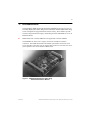
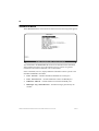
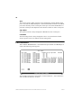
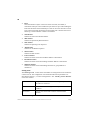
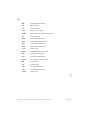
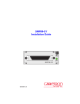
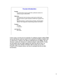
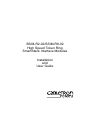
SSIM-R2-02/SSIM-R8-02
High Speed Token Ring
SmartStack Interface Modules
Installation
and
User Guide
i
Notice
Cabletron Systems reserves the right to make changes in specifications and other
information contained in this document without prior notice. The reader should in all
cases consult Cabletron Systems to determine whether any such changes have been made.
The hardware, firmware, or software described in this manual is subject to change
without notice.
IN NO EVENT SHALL CABLETRON SYSTEMS BE LIABLE FOR ANY
INCIDENTAL, INDIRECT, SPECIAL, OR CONSEQUENTIAL DAMAGES
WHATSOEVER (INCLUDING BUT NOT LIMITED TO LOST PROFITS) ARISING
OUT OF OR RELATED TO THIS MANUAL OR THE INFORMATION CONTAINED
IN IT, EVEN IF CABLETRON SYSTEMS HAS BEEN ADVISED OF, KNOWN, OR
SHOULD HAVE KNOWN, THE POSSIBILITY OF SUCH DAMAGES.
© October 1999 by:
Cabletron Systems, Inc.
35 Industrial Way
Rochester, NH 03867
All Rights Reserved.
Order Number: 9032961-01
(DOC-7059 v. 1.1, 710001813)
SmartStack is a trademark of Cabletron Systems, Inc.
CompuServe is a registered trademark of CompuServe, Inc.
i960 microprocessor is a registered trademark of Intel Corp.
Ethernet is a trademark of Xerox Corporation.
Notice
ii
FCC Notice
This device complies with Part 15 of the FCC rules. Operation is subject to the following
two conditions: (1) this device may not cause harmful interference, and (2) this device
must accept any interference received, including interference that may cause undesired
operation.
NOTE: This equipment has been tested and found to comply with the limits for a Class A
digital device, pursuant to Part 15 of the FCC rules. These limits are designed to provide
reasonable protection against harmful interference when the equipment is operated in a
commercial environment. This equipment uses, generates, and can radiate radio
frequency energy and if not installed in accordance with the operator’s manual, may cause
harmful interference to radio communications. Operation of this equipment in a
residential area is likely to cause interference in which case the user will be required to
correct the interference at his own expense.
WARNING: Changes or modifications made to this device which are not expressly
approved by the party responsible for compliance could void the user’s authority to
operate the equipment.
VCCI Notice
This is a Class A product based on the standard of the Voluntary Control Council for
Interference by Information Technology Equipment (VCCI). If this equipment is used in a
domestic environment, radio disturbance may arise. When such trouble occurs, the user
may be required to take corrective actions.
Industry Canada Notice
This digital apparatus does not exceed the Class A limits for radio noise emissions from
digital apparatus set out in the Radio Interference Regulations of the Canadian
Department of Communications.
Le présent appareil numérique n'émet pas de bruits radioélectriques dépassant les limites
applicables aux appareils numériques de la class A prescrites dans le Règlement sur le
brouillage radioélectrique édicté par le ministère des Communications du Canada.
Notice
iii
Declaration of Conformity
Addendum
Application of Council Directive(s): 89/336/EEC
73/23/EEC
Manufacturer’s Name: Cabletron Systems, Inc.
Manufacturer’s Address: 35 Industrial Way
PO Box 5005
Rochester, NH 03867
European Representative Name: Mr. J. Solari
European Representative Address: Cabletron Systems Limited
Nexus House,
Newbury Business Park
London Road, Newbury
Berkshire RG13 2PZ, England
Conformance to Directive(s)/Product Standards: EC Directive 89/336/EEC
EC Directive 73/23/EEC
EN 55022
EN 50082-1
EN 60950
Equipment Type/Environment: Networking Equipment, for use
in a Commercial or Light
Industrial Environment.
We the undersigned, hereby declare, under our sole responsibility, that the equipment
packaged with this notice conforms to the above directives.
Manufacturer
Legal Representative in Europe
Mr. Ronald Fotino
Full Name
Mr. J. Solari
Full Name
Principal Compliance Engineer
Title
Managing Director - E.M.E.A.
Title
Rochester, NH, USA
Location
Newbury, Berkshire, England
Location
Notice
iv
Notice
v
Table of Contents
1. Introduction
1
2. Installation
3
Package Contents . . . .
Installation Procedure . .
Hardware Installation . .
Software Installation . . .
TFTP Download . . .
Serial Download . . .
Cabling . . . . . . . . . .
LEDs . . . . . . . . . . .
Power-On Self Test . . .
Configuration . . . . . .
Default Configuration
.
.
.
.
.
.
.
.
.
.
.
.
.
.
.
.
.
.
.
.
.
.
.
.
.
.
.
.
.
.
.
.
.
.
.
.
.
.
.
.
.
.
.
.
.
.
.
.
.
.
.
.
.
.
.
.
.
.
.
.
.
.
.
.
.
.
.
.
.
.
.
.
.
.
.
.
.
.
.
.
.
.
.
.
.
.
.
.
.
.
.
.
.
.
.
.
.
.
.
.
.
.
.
.
.
.
.
.
.
.
.
.
.
.
.
.
.
.
.
.
.
.
.
.
.
.
.
.
.
.
.
.
.
.
.
.
.
.
.
.
.
.
.
.
.
.
.
.
.
.
.
.
.
.
.
.
.
.
.
.
.
.
.
.
.
.
.
.
.
.
.
.
.
.
.
.
.
.
.
.
.
.
.
.
.
.
.
.
.
.
.
.
.
.
.
.
.
.
.
.
.
.
.
.
.
.
.
.
.
.
.
.
.
.
.
.
.
.
.
.
Introduction . . . . . . . . . . . . . . . .
Ports, Port Groups and VLANs . . . .
HSTR Virtual Ports and VLAN Tagging
Virtual Port Restriction . . . . . . . . .
Ring Number Restriction . . . . . . . .
General Guidelines . . . . . . . . . . . .
Navigating within the Menus . . . . . .
Configuration Overview . . . . . . . . . .
Port Configuration - HSTR Ports . . . . .
Virtual Port Configuration . . . . . . . . .
.
.
.
.
.
.
.
.
.
.
.
.
.
.
.
.
.
.
.
.
.
.
.
.
.
.
.
.
.
.
.
.
.
.
.
.
.
.
.
.
.
.
.
.
.
.
.
.
.
.
.
.
.
.
.
.
.
.
.
.
.
.
.
.
.
.
.
.
.
.
.
.
.
.
.
.
.
.
.
.
.
.
.
.
.
.
.
.
.
.
.
.
.
.
.
.
.
.
.
.
.
.
.
.
.
.
.
.
.
.
3. Console Configuration
. 3
. 3
. 4
. 6
. 6
. 7
. 7
. 8
. 9
. 9
10
11
4. Statistics
12
12
13
13
14
14
15
15
16
18
21
Statistics Menu . . . . .
Port Status . . . . . . . .
Port Statistics . . . . . .
General Statistics . .
Virtual Port Statistics .
802.5 Statistics . . .
.
.
.
.
.
.
.
.
.
.
.
.
.
.
.
.
.
.
.
.
.
.
.
.
.
.
.
.
.
.
.
.
.
.
.
.
.
.
.
.
.
.
.
.
.
.
.
.
.
.
.
.
.
.
.
.
.
.
.
.
.
.
.
.
.
.
.
.
.
.
.
.
5. Getting in Touch with Technical Support
.
.
.
.
.
.
.
.
.
.
.
.
.
.
.
.
.
.
.
.
.
.
.
.
.
.
.
.
.
.
.
.
.
.
.
.
.
.
.
.
.
.
.
.
.
.
.
.
22
23
24
25
30
31
33
Problem Report Form . . . . . . . . . . . . . . . . . . . . . . 34
Appendix A. Abbreviations
37
SSIM-R2-02/SSIM-R8-02 HSTR SmartStack Interface Modules Installation and User Guide
vi
List of Figures
Figure 1. SSIM-R2-02 High-Speed Token Ring
SmartStack Interface Module . . . . . . . . . . . . . . . . . 1
Figure 2. Removing the Expansion Slot Cover . . . . . . . . . . . . . 5
Figure 3. Inserting the Module . . . . . . . . . . . . . . . . . . . . . . 5
List of Tables
Table 1.
Table 2.
Table 3.
Table 4.
Table 5.
Table 6.
LEDs at the Left on the Front Panel . . . . . . .
LEDs at the Right of Every Port . . . . . . . . .
HSTR Port Configuration: Status Values . . . . .
Virtual Port Configuration: Status Values. . . . .
Virtual Port Configuration: Maximum Frame Size
Config Loss Values . . . . . . . . . . . . . . . .
SSIM-R2-02/SSIM-R8-02 HSTR SmartStack Interface Modules Installation and User Guide
.
.
.
.
.
.
.
.
.
.
.
.
.
.
.
.
.
.
.
.
.
.
.
.
.
.
.
.
.
.
.
.
.
.
.
.
. 8
. 9
. 16
. 18
. 19
. 26
1
1. Introduction
The SmartStack SSIM-R2-02 and SmartStack SSIM-R8-02 provide two ports of
100 Mbps High-Speed Token Ring for the SmartStack STS16-20RM Token Ring
switch. Designed for high performance and low latency, these modules provide
seamless integration between legacy Token Ring networks and HSTR servers or an
HSTR backbone.
➽
Note: References to STS16-20RM are also applicable to STS16-20FRM.
The SSIM-R2-02 offers UTP-5 copper connections with RJ-45 interface
connectors. The SSIM-R8-02 offers multimode optical fiber connections with
VF-45 interface connectors.You can mount either of them in one of the two frontpanel expansion slots on the STS16-20RM switch.
Figure 1. SSIM-R2-02 High-Speed Token Ring
SmartStack Interface Module
Introduction
SSIM-R2-02/SSIM-R8-02 HSTR SmartStack Interface Modules Installation and User Guide
2
The SSIM-R2-02 and SSIM-R8-02 conform to the IEEE 802.5t standard for 100
Mbps High-Speed Token Ring, and implement the standard DTR MAC protocol.
An HSTR port can connect to a standard HSTR adapter or it can act as a trunk port
and carry traffic from up to 63 VLANs configured in the switch. This is achieved
using standard IEEE 802.1Q VLAN frame tagging. For each VLAN a virtual port
is created that behaves much like an ordinary Token Ring port.
The module enables standard Token Ring source routing and supports all the
switching modes implemented in the switch.
Six LEDs on the front panel indicate the overall operational state of the module and
the two ports. Configuration and detailed status information is available from the
switch console or from the graphical management application.
❏
SSIM-R2-02/SSIM-R8-02 HSTR SmartStack Interface Modules Installation and User Guide
Introduction
3
2. Installation
This chapter describes how to install, connect, and start using the SSIM-R2-02 or
SSIM-R8-02. The following main topics are covered:
•
•
•
•
•
•
•
•
Package Contents
Installation Procedure
Hardware Installation
Software Installation
Cabling
LEDs
Power-On Self Test
Configuration
Package Contents
Your SSIM-Rx-02 package contains the following items:
•
One SmartStack SSIM-R2-02 High-Speed Token Ring SSIM (UTP)
OR
one SmartStack SSIM-R8-02 High-Speed Token Ring SSIM (MMF).
•
One SSIM-R2-02/SSIM-R8-02 High-Speed Token Ring SmartStack Interface
Module Guide to Operations (this manual).
Installation Procedure
The SSIM-R2-02 and SSIM-R8-02 are packaged with software for both the module
itself and the SmartStack Token Ring switch. The switch is also supplied with both
software images. To ensure compatibility between the module and the switch,
install the latest of the software versions.
The software for the switch and the module is also available via Cabletron’s online
services (Internet, FTP).
Install the module, as follows:
1. Install the software in the SmartStack Token Ring switch. See the switch
manual for instructions on downloading the software.
2. Optional: Clear the NVRAM in the base switch. This will erase all
configuration in the switch.
Installation
SSIM-R2-02/SSIM-R8-02 HSTR SmartStack Interface Modules Installation and User Guide
4
3. Reset the switch to activate the new software.
4. If you cleared NVRAM in step 2, re-establish the switch configuration. Verify
that the switch is operating correctly.
5. Power off the switch
➽
Warning: Be sure to install a version of the base switch software that supports the
SSIM-Rx-02 (version 3.00 or later) before physically inserting the SSIM-Rx-02.
Otherwise, the switch will not recognize it and this may in some cases corrupt the
configuration.
6. Physically install the SSIM-Rx-02 in one of the two expansion slots. See section
“Hardware Installation” on page 4 for detailed instructions.
7. Power on the switch.
8. Download the software for the SSIM-Rx-02. See section “Software
Installation” on page 6 for detailed instructions.
9. If you plan to use the graphical switch manager application, install it now.
10. If necessary, configure the module. For details, see the section “Configuration”
on page 9 as well as Chapter 3, “Console Configuration”.
Hardware Installation
To install the SSIM-R2-02 and SSIM-R8-02 in a SmartStack STS16-20RM or
STS16-20FRM switch:
1. Power off the base switch by unplugging the power cord from the power outlet.
If the switch uses the optional SmartStack STS-PSU Redundant Power Supply
Unit, unplug the connector from the base switch as well.
2. Select an empty expansion module slot in which to install the SSIM-Rx-02. You
can install the module in either or both of the slots.
3. Loosen the two screws on the expansion slot cover plate and remove the cover
See Figure 2. Keep the plate for use in the event that the expansion module is
later removed.
SSIM-R2-02/SSIM-R8-02 HSTR SmartStack Interface Modules Installation and User Guide
Installation
5
Figure 2. Removing the Expansion Slot Cover
➽
Warning: Expansion modules are not hot-swappable. If you install or remove
expansion modules while the power to the switch is on, damage may occur to the
switch and to the module.
4. Carefully insert the SSIM-Rx-02 into the rails on each side of the expansion
slot, and slide the module back until the connector on the module is seated into
the connector at the back of the slot. See Figure 3. When the module is fully
seated, the module faceplate will be flush with the front of the base switch.
Figure 3. Inserting the Module
5. Secure the SSIM-Rx-02 with the two attached thumb screws.
6. Reapply power to the switch.
Installation
SSIM-R2-02/SSIM-R8-02 HSTR SmartStack Interface Modules Installation and User Guide
6
Software Installation
Before you can use your SSIM-Rx-02, you must install the SSIM-Rx-02 software
image which you can download to the SSIM-Rx-02 via TFTP or via a serial line.
TFTP Download
1. On the disks supplied with the module, find the image file. The file name is of
the form HSTRyyzz.BIN where yyzz is the version number of the software. For
example HSTR400.BIN is version 4.00 of the software image.
2. Copy the software image file to a directory on the TFTP server.
3. On the main menu in the console, select Download/Upload to display the
Download/Upload menu.
4. Select TFTP Download/Upload to display the TFTP Download/
Upload menu:
5. On this menu, set the IP address of the TFTP server. Also, set the download
VLAN (the BRF on which the TFTP server is located).
6. Select HSTR Firmware Download to display the HSTR Firmware
TFTP Download screen.
7. Select HSTR Firmware Download Filename and type the filename of
the software image to download.
8. Select Execute HSTR Image Network Download to start the
download.
While the software is transferred over the network, the console will display
SSIM-R2-02/SSIM-R8-02 HSTR SmartStack Interface Modules Installation and User Guide
Installation
7
messages describing download activity. When the software has been transferred,
you will see the following messages:
Network download complete.
Module(s), please wait...
Now transferring to HSTR
Download of HSTR firmware complete – HSTR module(s)
being reinitialized...
The software image is then programmed into the nonvolatile memory on the SSIMRx-02. When software installation is complete, the module starts for normal
operation, and the following message is displayed:
Press <RETURN> to continue...
Serial Download
1. On the discs supplied with the module, find the software image file. The file
name is of the form HSTRyyzz.BIN where yyzz is the version number of the
software. For example HSTR0310.BIN is version 3.10 of the software image.
Copy the software image file to a directory on the TFTP server.
2. From the main menu, select Download/Upload to display the Download/
Upload menu.
3. Select Serial Link Download. The Serial Link Download screen
is displayed.
4. Select HSTR Firmware Download.
5. Using your terminal software, transfer the software image to the module with
the X-Modem protocol. The transfer will take some minutes depending on your
terminal emulator baud rate.
The software image is then programmed into the FLASH memory of the module,
and will remain there until it is replaced. When the software installation is
complete, the module is started for normal operation, and the following message is
displayed:
Press <RETURN> to continue...
Cabling
The cabling required depends on the version of the SSIM-Rx-02 you are installing.
SmartStack SSIM-R2-02 2-port High-Speed Token Ring SSIM (UTP5)
The UTP module uses standard UTP Category 5 copper cables. The maximum
cable length is 100 m (328 feet).
Installation
SSIM-R2-02/SSIM-R8-02 HSTR SmartStack Interface Modules Installation and User Guide
8
1. Insert the modular RJ-45 jack from either end of a standard UTP-5 cable inton
one of the connectors on the SSIM-R2-02 front panel.
2. Connect the other end of the cable to either another HSTR switch port (for
example, another module) or an HSTR adapter.
3. If the default Auto port mode is in effect, the port will automatically open in the
appropriate Port or Station mode. Refer to Chapter 3, “Console Configuration”
for details on port mode configuration.
The SSIM-R2-02 also supports IBM type 1 STP copper cables (150 Ohm), which
have a maximum length of 100m (328 feet). To use an STP cable, then balluns with
an RJ-45 connector are required.
SmartStack SSIM-R8-02 2-port High-Speed Token Ring SSIM (MMF)
The MMF module uses multimode 62.5/125 micron fiber cables with a maximum
cable length of 2000 m (6560 feet).
1. Connect a VF-45 optic fiber to the VF-45 connector on the front panel of the
SSIM-R2-02. To ensure a proper connection, it may be necessary to clean the
fiber connectors with a soft tissue dipped in alcohol.
2. Connect the other end of the cable to either another HSTR switch port (for
example, another SSIM-Rx-02) or an HSTR adapter.
3. If the default Auto port mode is in effect, the port will automatically open in the
appropriate Port or Station mode. Refer to Chapter 3, “Console Configuration”
for details on port mode configuration.
LEDs
There are six LEDs on the front panel of the SSIM-Rx-02. During normal
operation, the two LEDs on the left side of the front panel indicate the module
status:
LED
DIAG (green)
ERR (yellow)
Position
Top
Bottom
State
Meaning
On
Diagnostics are in process.
Off
No diagnostics are in process.
On
A module failure has occurred.
Off
The module is working correctly.
Table 1. LEDs at the Left on the Front Panel
SSIM-R2-02/SSIM-R8-02 HSTR SmartStack Interface Modules Installation and User Guide
Installation
9
The two LEDs on the right of every port indicate the port status:
LED
LINK (green)
ACTIVITY
(green)
Position
Top
Bottom
State
Meaning
On
The port has link and is inserted.
Flashing
The port is disabled.
Off
The port is not inserted.
Flashing
The port is receiving and/or
transmitting LLC frames.
Off
Currently no LLC traffic on the
port.
Table 2. LEDs at the Right of Every Port
Power-On Self Test
When the switch is powered on, it will run a self test to ensure that all devices are
working correctly. During this test, the switch will detect and start any
SSIM-Rx-02s in its expansion slot.
The module will then perform an internal power-on self-test. The test takes a few
minutes. During this time, the DIAG and ERR LEDs will remain lit and the other
LEDs may turn on and off.
If the test reveals no problems, at the end of the test the DIAG and ERR LEDs will
turn off and the module will enter its normal operation state.
If the test reveals a problem, at the end of the test the DIAG LED will turn off.
Messages in the message log or on the console will describe the problem.
Configuration
The are two ways to manage SSIM-R2-02 and SSIM-R8-02:
•
From the switch console, via Telnet or directly with a VT100 terminal
emulator on the RS-232 port
•
Through the SNMP-based graphical management application SmartStack
Manager.
•
Installation
SSIM-R2-02/SSIM-R8-02 HSTR SmartStack Interface Modules Installation and User Guide
10
Chapter 3, “Console Configuration”, describes console comfiguration. The
management application is described its online help.
All configuration parameters are stored by the switch and not by the module. This
means that modules can be exchanged without reconfiguring the switch.
Note, however, that the SSIM-Rx-02 software image is stored on the module itself
and will follow the module if you move it to another switch.
Default Configuration
When a SSIM-Rx-02 is inserted into an expansion slot for the first time, the switch
will assume the default configuration. Each HSTR port:
•
•
•
is enabled.
is set to Auto mode.
has one virtual port in the default CRF.
This configuration is suitable for connecting both HSTR adapters and other HSTR
switch ports to the default CRF. If more advanced configurations are required, refer
to Chapter 3, “Console Configuration” for details.
❏
SSIM-R2-02/SSIM-R8-02 HSTR SmartStack Interface Modules Installation and User Guide
Installation
11
3. Console Configuration
This chapter explains how to view and edit the configuration of the SSIM-R2-02
and SSIM-R8-02 using a VT100 terminal emulator attached directly to a
SmartStack STS16-20RM switch. The SSIM-Rx-02 configuration can also be
modified from a remote VT100 console via a Telnet session. Connecting a network
management console is explained in the manual supplied with the SmartStack
STS16-20RM switch.
The following topics are explained in this chapter:
•
•
•
•
•
Introduction
General Guidelines
Configuration Overview
Port Configuration—HSTR Ports
Virtual Port Configuration
For more information on configuration, please see the SmartStack STS16-20RM/
STS16-20FRM Token Ring Switch Installation and User Guide.
Console Configuration
SSIM-R2-02/SSIM-R8-02 HSTR SmartStack Interface Modules Installation and User Guide
12
Introduction
The SSIM-Rx-02 has two 100 Mbit HSTR ports. In the console configuration, port
numbers are used to refer to ports, with the ordinary Token Ring ports being
numbered 1 to 20. If the module is inserted into the left expansion slot, the HSTR
ports are number 21 and 22. If the module is inserted into the right expansion slot,
the HSTR ports are number 25 and 26. Any number of SSIM-Rx-02s may be
inserted into a stack of Token Ring switches.
The HSTR ports are configured much like ordinary Token Ring ports, and
generally appear in all tables where ordinary Token Ring ports appear.
Ports, Port Groups and VLANs
This section briefly describes the VLAN concept and switching modes of the
SmartStack STS16-20RM Token Ring switch. For more information about these
subjects, refer to the SmartStack STS16-20RM Token Ring Switch Installation and
User Guide.
The SmartStack STS16-20RM Token Ring switch supports up to 63 VLANs. A
VLAN forms a single bridged domain. The visibility of MAC addresses, bridge and
ring numbers as well as the scope of broadcast frames are limited to the VLAN in
which they origin. Frames must be routed to move between VLANs.
A VLAN consists of a number of port groups called a Concentrator Relay Function
(CRFs). A CRF is conceptually equal to a ring. If a VLAN contains two or more
CRFs they are conceptually connected by a multiport bridge called a Bridge Relay
Function (BRF).
The BRF performs either Source-route bridging (SRB) or Source-route transparent
(SRT) switching between the CRFs depending on the CRF configuration. The
CRFs configured for SRT switching form a SRT domain, in which source-routed
frames are source routed and non-source-routed frames are transparently switched.
Each ordinary Token Ring port is assigned to a specific CRF, which also
determines which VLAN it belongs to.
SSIM-R2-02/SSIM-R8-02 HSTR SmartStack Interface Modules Installation and User Guide
Console Configuration
13
HSTR Virtual Ports and VLAN Tagging
The HSTR ports behave much like ordinary Token Ring ports. They implement the
DTR TXI MAC layer protocol as specified in the IEEE 802.5t specification and can
be configured for Port, Station or Auto sensing modes. Also, before a port is
inserted, the MAC layer protocol must complete the lobe test, which verifies the
cable connection.
HSTR ports differ significantly from ordinary Token Ring ports, however, in that
HSTR ports can function as trunk ports, which means that they can carry traffic
belonging to all possible 63 VLANs over the same physical cable connection.
Frames from different VLANs are distinguished by means of standard IEEE
802.1Q frame tags. A frame tag consists of an 8-byte SNAP protocol header
followed by a 2-byte Tag Control Information (TCI) field. It is inserted in the
Token Ring frame after the route information field before transmission on HSTR
and subsequently recognized and removed when the frame is received.
The TCI field identifies which VLAN the frame belongs to by means of a 12-bit
VLAN identifier. This VLAN identifier uniquely identifies the BRF. It also
contains a 3-bit priority field, which is described in section “Virtual Port
Configuration” under subsection “FC Modification”.
Each HSTR port can be assigned to several CRFs, but there can only be one HSTR
port per BRF/VLAN. A virtual port is created for each CRF to which the HSTR port
is assigned. All virtual ports but one must be tagged. In other words, a single virtual
port can be left untagged. Also see section “Virtual Port Configuration” on page 18.
Note that a HSTR port with a single untagged virtual port is functionally equivalent
to an ordinary Token Ring port. This is also the default configuration, with the
virtual port in trcrf-default.
Virtual Port Restriction
➽
Note: A HSTR port can only have one virtual port in each VLAN.
This follows from the nature of VLAN tagging. It would not be possible to
distinguish frames from two virtual ports in the same VLAN, since they would have
the same VLAN identifier.
Console Configuration
SSIM-R2-02/SSIM-R8-02 HSTR SmartStack Interface Modules Installation and User Guide
14
Ring Number Restriction
➽
Note: All CRFs that a HSTR port has virtual ports in must have the same ring
number.
Thus, the ring number is a per-port parameter and not a per-virtual port parameter.
This convention will also be implemented by HSTR switches and is expected to be
adopted by the IEEE. To see the importance of this, consider the implication of not
having this restriction. If it was not in effect, the meaning of the RIF would be
ambiguous and depend on to which VLAN the frame was sent. It would thus be
incomprehensible to equipment that does not understand VLAN tags.
When a virtual port is created in a VLAN this restriction might in some cases
require that a new CRF be created to avoid changing existing ring numbers.
General Guidelines
To work within the console menus, follow these guidelines:
•
To select a menu item, use the arrow keys to move the “highlight” over the
selection, then press Enter.
•
If you need to specify additional information for any item—for example,
selecting Yes or No or supplying a value—a prompt appears on the screen. If
you want to exit the prompt without changing the value, press Esc.
•
•
In most cases, new values are saved when you select Return.
The term “More” means there is more information than what is displayed on
that screen. Selecting More and pressing Enter displays the next screen of
information. If the screen is a one-screen display, selecting More will update
the screen.
•
The term “Port” refers to the number of a specific port on a SmartStack STS1620RM.
•
•
“Index” refers to the numerical order of a list.
•
•
To refresh the console panel at any time, press Ctrl-L.
To return to the main menu from any screen within the menus, press Ctrl-P.
Note that any changes made to the screen you were in are not saved. To return
to the greeting screen, press Ctrl-B from any screen.
If you are administering switches in a stack, many of the console screens will
prompt for a box number. Enter the number of the box you want to administer
to continue. The box that you are physically connected to is highlighted.
SSIM-R2-02/SSIM-R8-02 HSTR SmartStack Interface Modules Installation and User Guide
Console Configuration
15
•
The console automatically returns to the greeting screen after five minutes of
inactivity. Five minutes is the default value. The time can be changed at the
Console Configuration menu. The Console Configuration
menu is within the Configuration menu, under the main menu.
•
For protection against inadvertent or unauthorized access to configuration
screens, you can set a password that users must enter at the Greeting screen. If
no password is configured, just press Enter and the main menu is presented.
Navigating within the Menus
Use the arrow keys (also referred to as cursor keys) to move the highlight over a
selection. If the selection is a menu, pressing the Enter key displays a new screen of
information; if the selection is a command, such as Reset, pressing the Enter key
initiates that function.
A heading with three “dots” after it means that when that heading is selected, a
submenu or screen is displayed. Unless specified differently, all the screens or
menus are accessed in the same way.
Configuration Overview
Execute the following general steps to configure a SSIM-Rx-02:
•
•
•
•
Determine which VLANs the HSTR ports should connect.
•
Assign CRFs to the HSTR port, thereby creating one virtual port in each
VLAN. You can create new CRFs to make sure that the CRFs do not have
conflicting ring numbers, as discussed in “Ring Number Restriction” on
page 14.
•
•
Configure the HSTR port, in particular the operation mode.
Determine which VLAN, if any, should be untagged.
Configure the 802.1Q VLAN ID for all the BRFs that should be tagged.
Make sure that each 802.1Q VLAN ID matches that of the HSTR equipment
on the other end.
Configure the virtual ports, in particular the tagging mode. The relevant
configuration menus are described in the port configuration sections.
Console Configuration
SSIM-R2-02/SSIM-R8-02 HSTR SmartStack Interface Modules Installation and User Guide
16
Port Configuration - HSTR Ports
To configure an HSTR port on the SSIM-Rx-02, select Port Configuration
from the Configuration menu and enter the port number of the HSTR port (21,
22, 25, or 26). The following menu appears:
The following items are shown:
Enabled
Detemines whether the port is enabled, Yes or No. When the port is disabled, the
LINK LED will blink. This is also the case, if the port has been auto-disabled, see
“Cfg Loss Threshold” and “Cfg Loss Sampling Interval” on page 17” .
Default: Yes.
Status
Display only. Shows the current status of the port. Can be one of the following:
Value
Meaning
Auto Disabled
The port has been auto disabled.
Down
The port has been disabled and the MAC protocol is
disconnected.
Table 3. HSTR Port Configuration: Status Values
SSIM-R2-02/SSIM-R8-02 HSTR SmartStack Interface Modules Installation and User Guide
Console Configuration
17
Value
Meaning
Going Up
The port is enabled and the MAC protocol is trying to
connect.
Up
The port is up and the MAC protocol has connected.
Going Down
The port has been disabled and the MAC protocol is
disconnecting.
Temporary Down
The MAC protocol has disconnected, but is actively
trying to connect again. The disconnect reason might be
a wire fault or configuration change.
Table 3. HSTR Port Configuration: Status Values
Operation Mode
Sets the operation mode of the port. Possible configured values are FDX port, FDX
station and Auto. On an HSTR connection, one end must be a FDX port and the
other a FDX station. An HSTR adapter is always a FDX station, where a switch port
can be both. The Auto mode will attempt to detect the port mode automatically by
switching between the two modes with a period of a few seconds.
When the port connects in the Auto mode, the detected mode is shown as A-FDX
port or A-FDX station.
Default: Auto.
Cfg Loss Threshold
Sets the number of configuration losses before the port auto-disables. Possible
values are 1 to 100 or Disabled. The MAC protocol generates a configuration loss
in case of lobe test failure, heartbeat failure, address change or other MAC protocol
error.
Default: 8.
Cfg Loss Sampling Interval
Sets the sampling interval in which the Cfg Loss threshold must be exceeded for
the port to auto disable. Possible values are 1 to 60 minutes.
Default: 1.
Address Demand Aging Level
Sets the threshold on the number of entries in the address table on which entries are
aged faster. Possible values are 50, 60, 70, 80 and 90 percent and Disabled.
Default: 90 percent.
Console Configuration
SSIM-R2-02/SSIM-R8-02 HSTR SmartStack Interface Modules Installation and User Guide
18
Virtual Port Configuration
To configure a virtual port on an HSTR port select Virtual Port
Configuration on the HSTR Port Configuration menu. If the HSTR
port has more than one virtual port, a list of the corresponding CRFs appears from
which the virtual port must be selected. The following menu appears:
Enabled
Sets the administrative state of the virtual port, possible values are Yes and No.
Default: Yes.
Status
Display only. Shows the current status of the virtual port. Can be one of the
following:
Value
Meaning
Admin down
The port or virtual port is disabled.
Waiting for port up
The virtual port is waiting for the port to come up.
Up
The virtual port is up but not forwarding.
Forwarding
The virtual port is up and forwarding.
Table 4. Virtual Port Configuration: Status Values
SSIM-R2-02/SSIM-R8-02 HSTR SmartStack Interface Modules Installation and User Guide
Console Configuration
19
Value
Temporary down
Meaning
The virtual port is currently down because the port is
temporary down.
Table 4. Virtual Port Configuration: Status Values
MTU
Sets the maximum frame size for the virtual port, possible values are 1500, 4472,
8144, 17800, and Use BRF. These values correspond to the standard values used
on the ordinary Token Ring ports. Actually, slightly larger frame sizes are allowed
to accommodate the frame sizes defined by the ATM Forum LAN Emulation
standard and implemented by the SmartStack SSIM-Ax-01 module. Also, the IEEE
802.1Q frame tag adds another 10 bytes to each frame.
Table 5 shows the configured and actual frame size, as well as the corresponding
Largest Frame Size bits that are used in explorer RIF expansion:
MTU configured
Actual HSTR frame size
LF bits
1500
1558
001
4472
4556
011
8144
9246
100
17800
18202
110
Table 5. Virtual Port Configuration: Maximum Frame Size
Also shown is the actual MTU for the BRF. If Use BRF is selected, the BRF value
will be used. Otherwise, the lowest of the BRF MTU and port MTU values will be
used. Thus, a port will never have a higher MTU than its BRF.
Range: 1500, 4472, 8144, 17800, and Use BRF
Default: Use BRF.
Max Explorer Rate
Sets the maximum explorer frame rate. If enabled, this will limit the amount of
explorer frames being forwarded from the HSTR side of the virtual port to the
switch.
Range: 0 to 5000 frame/sec or Disabled
Default: Disabled.
Console Configuration
SSIM-R2-02/SSIM-R8-02 HSTR SmartStack Interface Modules Installation and User Guide
20
VLAN Tagging Mode
Sets the VLAN tagging mode of the virtual port. As explained previously, one
virtual port on each HSTR port can be untagged. All other ports must be tagged and
each of these virtual ports must use a unique 802.1Q VLAN ID with the same
physical port. The 802.1Q VLAN ID can be configured for the TrBRE
configuration. Refer to the SmartStack STS16-20RM Token Ring Installation and
User Guide. When configuring the Tagging mode and the 802.1Q VLAN ID, make
sure that the same Tagging mode and 802.1Q VLANs are used at both ends.
Preferably, the VLAN which is expected to have the largest amount of traffic
should be untagged, since VLAN tagging does impose a small overhead.
Default: Untagged (first virtual port)
Default: Tagged (following ports)
FC Modification
Enables or disables FC modification when a frame tag is removed, possible values
are Enabled and Disabled. As discussed earlier a VLAN frame tag also contains a
3 bit priority field. If FC modification is enabled, the Token Ring frame priority in
the FC byte is overwritten with the frame tag priority, if the frame tag priority is not
equal to zero. If FC modification is disabled, the FC priority is left as it is, and the
frame tag priority is discarded.
When the SSIM-Rx-02 inserts a frame tag in a frame, it always uses the FC priority
as the frame tag priority, so for frames received from another module, this option
makes no difference. Other devices, however, might require that the frame tag
priority should take precedence, in which case FC modification should be enabled.
Default: Disabled.
Address Aging Time
Sets the aging time for addresses learned on an HSTR port. When there has been
no activity on an address for the specified period of time it is deleted from the
address tables.
Range 1 to 9999 minutes or 0 (for disabled).
Default: 5 minutes.
❏
SSIM-R2-02/SSIM-R8-02 HSTR SmartStack Interface Modules Installation and User Guide
Console Configuration
21
4. Statistics
A wide range of statistics is available for the SmartStack STS16-20RM Token Ring
switch. The following topics are discussed in this chapter:
•
•
•
•
•
•
Statistics
Statistics Menu
Port Status
Port Statistics
General Statistics
Virtual Port Statistics
802.5 MAC Information
SSIM-R2-02/SSIM-R8-02 HSTR SmartStack Interface Modules Installation and User Guide
22
Statistics Menu
When Statistics is selected from the main menu, the following menu appears:
The commands in the Statistics menu are all described in the SmartStack
STS16-20RM Token Ring Switch Installation and User Guide. For general
information about these commands, refer to that manual.
Some commands, however, display additional information that is specific to the
SmartStack SSIM-Rx-02 module:
•
•
•
•
Port Status—includes SmartStack SSIM-Rx-02 virtual ports.
Port Statistics—includes additional counters for HSTR ports.
Address Tables—includes addresses learned from HSTR ports.
Message Log Information—includes messages generated by the
module.
SSIM-R2-02/SSIM-R8-02 HSTR SmartStack Interface Modules Installation and User Guide
Statistics
23
Port Status
When Port Status is selected on the Statistics menu, a table similar to
the following appears:
Besides the ordinary Token Ring ports, the table contains an entry for each HSTR
virtual port, along with its current status. The following items are displayed:
Port
The HSTR port for which the virtual port is defined.
Range: 21, 22, 25, or 26.
TrCRF
The name of the CRF in which the virtual port is defined.
TrBRF
The name of the BRF in which the virtual port is defined.
Enabled/Ins
For ordinary Token Ring ports, this is the enabled and inserted status. This does not
apply to virtual ports on an HSTR port. Instead the current state of the virtual port
is displayed. Refer to the description of virtual port configuration for details.
Statistics
SSIM-R2-02/SSIM-R8-02 HSTR SmartStack Interface Modules Installation and User Guide
24
Spd
The connect speed in Mbps, which is always displayed as 100 for HSTR virtual
ports. Note that 100 Mbps full-duplex is the total bandwidth available on an HSTR
port and is shared by all the virtual ports on that port. The actual bandwidth on a
particular virtual port thus depends on the amount of traffic on other virtual ports.
Oper Mode
The operation mode is always displayed as HSTR VLAN for virtual ports.
Fwd Mode
The forwarding mode is always displayed as Store-Fwd, because the module
always operates in the store-and-forward switching mode.
Port Statistics
When Port Statistics is selected and the port number of an HSTR port is
entered, the following menu appears:
The available information is discussed in “General Statistics”, “802.5 Statistics”,
and “Virtual Port Statistics” sections.
SSIM-R2-02/SSIM-R8-02 HSTR SmartStack Interface Modules Installation and User Guide
Statistics
25
General Statistics
When General Statistics is selected on the HSTR Port Statistics
menu the following screen appears:
The screen shows the number of frames and bytes received, forwarded, and
transmitted on the HSTR port. These numbers include traffic for all virtual ports.
The screen is automatically updated every 5 seconds.
Frame and Byte Counters
The following frame and byte counters are defined:
Statistics
•
Received
Frames received from HSTR, but not necessarily forwarded.
•
Forwarded
Frames received from HSTR and forwarded to other ports in the switch.
•
Transmitted
Frames transmitted to HSTR.
•
Frames
The number of LLC frames received, forwarded, or transmitted. The number
is subdivided into the NSR, SRF, STE, and ARE frames. For received frames
it is also subdivided into unicast, broadcast and multicast frames. All are
explained later in this table.
SSIM-R2-02/SSIM-R8-02 HSTR SmartStack Interface Modules Installation and User Guide
26
•
Bytes
The total number of bytes in the LLC frames received, forwarded, or
transmitted. The byte count includes all bytes from AC up to and including the
FCS field. Note that the forwarded byte count can be lower than the received
byte count even though all frames are forwarded. This is because the VLAN
frame tag is removed before a frame is forwarded.
•
NSR Frames
Number of Non-Source Routed frames.
•
SRF Frames
Number of Specifically Routed Frames.
•
STE Frames
Number of Spanning Tree Explorers.
•
ARE Frames
Number of All-Routes Explorers.
•
MAC Frames
Number of MAC frames.
•
Unicast Frames
Number of frames with a unicast MAC address as destination.
•
Broadcast Frames
Number of frames with a Token Ring broadcast address as destination.
•
Multicast Frames
Number of frames with a Token Ring functional or group address as
destination.
Config Loss
The Config Loss counter shows the number of configuration losses within the
current interval. The configuration loss threshold and interval parameters are
described in Chapter 3, “Console Configuration”. The Config Loss Reason
can be one of these:
Wire Fault
The port was closed due to a wire fault, perhaps because
the cable was removed.
Lobe Test Fail
The lobe test failed during the recovery after a beacon
condition.
Heart Beat
The port was closed after a failure of the heartbeat
function.
Table 6. Config Loss Values
SSIM-R2-02/SSIM-R8-02 HSTR SmartStack Interface Modules Installation and User Guide
Statistics
27
TXI New Station
The port was closed after receiving a MAC frame with a
source address different from the stored Upstream
Neighbor address.
TXI Protocol
The port was closed due to a MAC TXI protocol error.
None
The port has never failed.
Table 6. Config Loss Values
Last Reset
The time since the last reset.
Reset
When Reset is chosen, all frame, byte, and discarded frame counters are reset.
Discarded Frames
When Discarded Frames is chosen on the general statistics display, the
following screen appears:
The screen shows the number of frames discarded on the HSTR port in both
inbound (from HSTR) and outbound (to HSTR) directions. The discard reasons are
described in the list that follows.
Statistics
SSIM-R2-02/SSIM-R8-02 HSTR SmartStack Interface Modules Installation and User Guide
28
Discarded Inbound Frames
The following discard reasons are defined for inbound frames:
•
Invalid VLAN
The frame was received on an unknown VLAN. The frame was either a VLAN
tagged frame containing an unknown VLAN ID, or an untagged frame when
no untagged virtual ports are defined. Make sure that the 802.1Q VLAN ID
and virtual port tagging mode is set to the same value on both sides of the
connection.
•
Invalid Route
Frame that held invalid Route Information Field (RIF) was received. Possible
reasons are, the frame:
— Had an odd or zero RIF length.
— Was to small to contain a RIF.
— Was an explorer frame with a backward RIF.
— Was a non-explorer frame with a RIF length of 4.
•
Invalid VLAN Tag CFI
A VLAN tagged frame had an invalid Canonical Format Indicator (CFI). The
CFI is a bit in the Tag Control Information field of a VLAN tag. This bit
indicates the bit order of any MAC addresses in the information field. It is 0 for
Ethernet format and 1 for Token Ring format. It should thus always be 1 in
received frames.
•
Ring Number Mismatch
A frame was discarded for one of two reasons
— In an explorer frame, the RIF length was larger than 2 and the ring number
of the HSTR port was not the last ring number in the RIF.
— In a non-explorer source-routed frame, the HSTR port ring number was
not in the RIF.
•
Duplicate Ring Number
A source-routed frame was discarded because it contained the HSTR port ring
number more than once. This could indicate a loop in the spanning tree.
•
Frame Too Large
The frame was larger than the maximum frame size, configured for the virtual
port. Refer to the table of maximum frame sizes in the description of virtualport configuration.
SSIM-R2-02/SSIM-R8-02 HSTR SmartStack Interface Modules Installation and User Guide
Statistics
29
•
Route Descriptor Too Large
An explorer frame had a RIF length that would exceed the configured
maximum hop count limit if more hops were added. The frame therefore was
forwarded only to the other ports in the same CRF as the receiving virtual port.
•
Filtered By Address Filter
A frame was discarded because of a MAC address filter.
•
Filtered By DSAP Filter
A frame was discarded because of a protocol (DSAP or protocol type) filter.
•
CRF Mismatch
A frame was discarded because the destination MAC address or destination
source-route hop was registered as local for the virtual port. That is, the frame
would have to be forwarded back to same port. This might be due to an error
in the configured HSTR VLAN ID for one or more VLANs.
•
Explorer Overflow
An explorer frame was discarded because the explorer throttle limit had been
exceeded.
•
Blocked Virtual Port
The virtual port was currently not in forwarding state. The blocked state may
have been permanent (because the spanning tree protocol has detected multiple
parallel paths) or transient (during network topology changes).
Discarded Outbound Frames
The following discard reasons are defined for outbound frames:
Statistics
•
Invalid Frame Header Tag
The frame had an invalid internal frame header tag (note that this internal
frame header tag is not the same as the VLAN tag).
•
Unknown Ring Number
An explorer frame was discarded because one or two ring numbers are required
for the RIF expansion and at least one of the required ring numbers was
unknown. The ring number must either be configured for the CRF or learned
from an incoming explorer frame.
•
Inactive Virtual Port
The virtual port was disabled.
•
Blocked Virtual Port
The virtual port was not in forwarding state. The blocked state may have been
permanent (because the spanning tree protocol detected multiple parallel
paths) or transient (during network topology changes).
•
Filtered By DSAP Filter
A frame was discarded because of a protocol (DSAP or protocol type) filter.
SSIM-R2-02/SSIM-R8-02 HSTR SmartStack Interface Modules Installation and User Guide
30
•
Frame Too Large
The frame was larger than the maximum frame size configured for the virtual
port. Refer to the table of maximum frame sizes in “Virtual Port
Configuration” on page 18.
•
Invalid Route
An explorer frame was not transmitted because the ring number of the HSTR
port appears earlier than the last ring number in the RIF.
For the following error conditions, transmission is aborted:
•
•
•
Unknown Ring Number
Frame Too Large
Invalid Route
This is because transmission has already begun at the time the error condition is
detected. The receiver on the other end will therefore count these frames as RX
aborts.
Virtual Port Statistics
When Virtual Port Statistics is selected from the HSTR Port
Statistics menu for an HSTR port, following screen appears for the selected
port:
SSIM-R2-02/SSIM-R8-02 HSTR SmartStack Interface Modules Installation and User Guide
Statistics
31
The following items are displayed:
Virtual Port State
The state of the virtual port. Refer to “Virtual Port Configuration” on page 18 for
details.
Frames Forwarded
The number of LLC frames received and forwarded on this virtual port.
Frames Transmitted
The number of LLC frames transmitted on this virtual port.
Frames Received
The number of LLC frames received, but not necessarily forwarded, on this virtual
port.
Last Reset
The time since these counters were last reset
Reset
Select Reset to reset the counters on this screen.
802.5 Statistics
When 802.5 Statistics is selected from the HSTR Port Statistics
menu, information about the Token Ring MAC layer protocol is displayed.
The information on this menu is similar to that for ordinary Token Ring ports. Refer
to the SmartStack STS16-20RM Token Ring Switch Installation and User Guide for
details.
❏
Statistics
SSIM-R2-02/SSIM-R8-02 HSTR SmartStack Interface Modules Installation and User Guide
32
SSIM-R2-02/SSIM-R8-02 HSTR SmartStack Interface Modules Installation and User Guide
Statistics
33
5. Getting in Touch with Technical Support
For additional support related to this device or document, contact Cabletron
Systems using one of the following methods:
World Wide Web
http://www.cabletron.com/
Phone
(603) 332-9400
Internet mail
[email protected]
FTP
ftp://ftp.cabletron.com/
anonymous
your email address
Login
Password
To send comments or suggestions concerning this document, contact the
Cabletron Systems Technical Writing Department via the following
email address: [email protected]
Make sure to include the document Part Number in the email message.
Before calling Cabletron Systems, have the following information ready:
•
•
•
Your Cabletron Systems service contract number
•
The serial and revision numbers of all involved Cabletron Systems products in
the network
•
•
•
A description of your network environment (layout, cable type, etc.)
•
Any previous Return Material Authorization (RMA) numbers
A description of the failure
A description of any action(s) already taken to resolve the problem (e.g.,
changing mode switches, rebooting the unit, etc.)
Network load and frame size at the time of trouble (if known)
The device history (i.e., have you returned the device before, is this a recurring
problem, etc.)
Getting in Touch with Technical Support
SSIM-R2-02/SSIM-R8-02 HSTR SmartStack Interface Modules Installation and User Guide
34
Problem Report Form
Fill in both sides of this Problem Report Form, print out the relevant system
configuration files and fax or mail to Cabletron Technical Support.
Switch Information
Switch type:
Hardware revision:
Software version:
Switch Configuration
Port configuration:
Adapter Information
Adapter type:
Operating system:
Network OS:
Driver name:
Driver version:
Company: ____________________________ Name: ______________________
Address: __________________________________________________________
Country: _______________________ Phone/Fax: ________________________
E-mail: _____________________
SSIM-R2-02/SSIM-R8-02 HSTR SmartStack Interface Modules Installation and User Guide
Getting in Touch with Technical Support
35
Problem Description
Network Installation Sketch
Getting in Touch with Technical Support
SSIM-R2-02/SSIM-R8-02 HSTR SmartStack Interface Modules Installation and User Guide
36
❏
SSIM-R2-02/SSIM-R8-02 HSTR SmartStack Interface Modules Installation and User Guide
Getting in Touch with Technical Support
37
Appendix A. Abbreviations
AC
Access Control
ARE
All-Routes Explorer
ATM
Asynchronous Transfer Mode
BRF
Bridge Relay Function
CFI
Canonical Format Indicator
CRC
Cyclic Redundancy Check
CRF
Concentrator Relay Function
DA
Destination Address
DSAP
Destination SAP
DTR
Dedicated Token Ring
ECO
Engineering Check Order
FC
Frame Control
FCS
Frame Check Sequence
FDX
Full Duplex
HDX
Half Duplex
HSTR
High-Speed Token Ring
IP
Internet Protocol
LAN
Local Area Network
LED
Light Emitting Diode
LLC
Logical Link Control
MAC
Media Access Control
Mbps
MegaBit Per Second
MMF
Multi Mode Fiber
MTU
Maximum Transmission Unit
NSR
Non-Source Routed
NVRAM
Non-Volatile RAM
RAM
Random Access Memory
SSIM-R2-02/SSIM-R8-02 HSTR SmartStack Interface Modules Installation and User Guide
38
RIF
Route Information Field
RX
Receive Data
SA
Source Address
SAP
Service Access Point
SNMP
Simple Network Management Protocol
SR
Source Routing
SRB
Source Route Bridging
SRF
Specifically Routed Frame
SRS
Source Route Switching
SRT
Source Route Transparent
SSAP
Source SAP
SSIM
SmartStack Interface Module
STE
Spanning Tree Explorer
TCI
Tag Control Information
TFTP
Trivial File Transfer Protocol
TR
Token Ring
TX
Transmit Data
TXI
Transmit Immediate
UTP
Unshielded Twisted Pair
VLAN
Virtual LAN
❏
SSIM-R2-02/SSIM-R8-02 HSTR SmartStack Interface Modules Installation and User Guide
Abbreviations
index-1
Index
Numerics
802.5 MAC information
31
port groups 12
port statistics menu 24
port status screen 23
problem report form 34
A
abbreviations
R
37
C
canceling a menu selection 14
configuration 9
console 11
default 10
console configuration 11
console, guidelines for using 14
CrosFire 865x
two types 1
refreshing the console panel
restrictions
ring number 14
virtual ports 13
14
S
self-tests 9
statistics 21
general 25
virtual ports 30
statistics menu 22
H
T
HSTR modules
configuration 9
HSTR ports 12
restrictions 13
three “dots”
15
U
I
using the menus
installation 3
cabling 7
physical 4
procedure for
software 6
introduction 1
14
V
virtual ports
statistics
VLANs 12
3
30
L
LEDs
8
M
menu navigation 15
message log 22
N
navigating in the menus
14, 15
P
package contents
Index
3
SSIM-R2-02/SSIM-R8-02 HSTR SmartStack Interface Modules Installation and User Guide
index-2
SSIM-R2-02/SSIM-R8-02 HSTR SmartStack Interface Modules Installation and User Guide
Index
* 710001813*