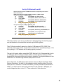
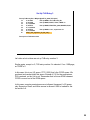
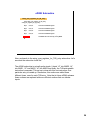
1
Course Introduction
Purpose
• The intent of this course is to describe a particular example of a
software program called eDINK.
Objectives
• Identify general rules for booting a system with an e500 device.
• Describe minimum system examples of eDINK and migration from
BATs.
• Describe expansion, including interrupt handlers, demand paging,
efficient TLB management, implementing protection and history.
Contents
• 39 pages
• 6 questions
Learning Time
• 60 minutes
In this course, we will cover an example of a software program called eDINK,
and we will discuss what we need to do in general for booting a system with
an e500 device, relating to the Memory Management Unit (MMU). We will
describe a particular example of a software program called eDINK. Finally,
we will explain how we might migrate from what we used to have, for
example a few block address translation (BAT) entries set up with a
PowerPC (PPC) Classic device, and how to translate that into an e500
environment.
1
Boot Code
•
•
Boot code
– Reset, set up at least one more page
– Set up more TLB entries to implement the initial memory map
– Set up the rest of the hardware
• Core resources (L1 caches, HIDs)
• Ex: MPC8560 memory controllers, on-chip peripherals
Interrupt handlers
– Instruction and Data TLB miss (error)—allocate more pages
– ISI and DSI: handle permissions violations
What do all systems need to do? Systems need to have some amount of
reset set up and at the very least, you need to set up the interrupt handlers.
At reset, at least one more page must be set up. The e500 interrupt
architecture is a little bit different from Classic. It has an Interrupt Vector
Prefix Register (IVPR) and then an individual Interrupt Vector Offset Register
(IVOR). It doesn’t define the offset for each interrupt; instead, it gives you a
register within which to put the offset for each interrupt.
Next, you may need to set up more TLB entries for the initial Memory Map.
In the case of the 8560 device that has the e500 core embedded, you’ll
probably set up the rest of the hardware, for example, the L1 caches, and
on-chip peripherals.
You also need to consider the interrupt handlers, and they will be discussed
later in this course.
2
Simplest Case: eDINK
Mouse over each question in the table for the answers.
Question
Answer
What is eDINK?
e500 core Demonstrative Interactive Nanokernel
(eDINK) is an enabling and debugging tool for e500based devices.
How do you get eDINK?
Go to www.freescale.com and search for “DINK.”
Executable eDINK, the instructions set simulator
(ISS), and full source for the eDINK debugger for the
e500 core processor are available.
What does eDINK run on?
Binary runs on e500 core ISS.
www.freescale.com
eDINK stands for e500 Core Demonstrative Interactive Nanokernel, and it’s
just a basic, simple debug monitor that has been developed in our lab for
debugging e500-based systems.
The easiest way to find the source code on the web is to do a search for
“DINK” on the Freescale site. The executable eDINK should be available,
and it’s been tested at least on the Instruction Set Simulator (ISS) where it’s
been running up to this point.
Move your mouse pointer over each question in the table for the answers.
3
Simplest Case: eDINK Features
MPC8540/60
•
•
•
•
•
•
Is ROM-resident (at 0xFF00_0000)
– PA of some of ROM overlaps with default CCSRBAR
(internal I/O for 8540/8560 @0xFF70_0000)
FF80_0000
Sets itself up (IVORS, a few TLBs)
FF70_0000
Copies itself to low RAM
– for performance
– eDINK doesn’t expect any interrupts until copy complete
Contains user exceptions
– reported and then code vectors back to eDINK
Runs in supervisor mode
Contains static memory map
CCSR
Let’s take a look at the eDINK features.
eDINK is ROM-resident, and one thing to note is that the ROM space starts at FF000000.
The 8540 and 8560 devices assume a default out of reset, and the 1 MB space from
FF70_0000 to FF80_0000 is where the Configuration and Control Status Register
(CCSR) space is defined as a default CCSR area. This area is contains all the
Configuration Registers for the on-chip peripherals of the 8540 and 8560. This can be
thought of, even though it’s all on-chip, as a kind of I/O space, but that resides within
this other space that we’re defining for our eDINK ROM. Note that in the future
releases of eDINK the CCSR area will be moved out of the ROM area.
eDINK assumes that memory map. It sets up itself, all the IVORs, and a few TLBs.
Then eDINK copies itself to low RAM so it’s not always running out of ROM, and it
doesn’t expect any interrupts until that copy is complete.
Then, eDINK has space for user code, but it doesn’t really do much for user exceptions
other than report them and then vector back to eDINK.
eDINK runs in supervisor mode, and it has a static memory map.
4
eDINK Memory Map
4 KB
eDINK
boot
1 MB
CCSR
1 MB
eDINK code
0xffff f000
branch to 0xFFFF_F000
boot code
0xffff fffc
0xffff f000
0xff80 0000
I/O Space (default)
0xff70 0000
0xff10 0000
eDINK code space
63 MB
1 MB
user code
copy
0xff00 3000
exception table
eDINK code 0x0000 0000
0xff00 0100
0xff00 0000
Next, let’s look at the eDINK memory map.
This page is certainly not to scale, but there is a 4 KB page at the very top of
memory where we have some boot code.
Then there is a CCSR space and the rest of the eDINK code.
The user code is down at low memory.
The eDINK code eventually gets copied down to low memory.
The very top instruction is a branch to the bottom of that 4 KB page.
Then there is that I/O space from FF70_0000 to FF80_0000 for the CCSR in
the 8540/8560.
This I/O space is 1 MB, and the rest of the eDINK code is another 1 MB
page. There is also the Exception Table and then eDINK code.
5
Question
Label the eDINK memory map by dragging the letters on the left to their correct
location on the right and click Done.
B
A
CCSR
B
boot
A
C
eDINK code
D
user code
E
eDINK code
E
D
C
Done
Reset
Show
Solution
Here is a question to check your understanding of the material presented so far.
Correct!
The eDINK memory map from top to bottom contains boot, CCSR, eDINK code,
user code and then eDINK code.
6
eDINK Memory Map
Click the user code section of the diagram to learn more.
entry #0 4 KB
eDINK
boot
entry #3 1 MB
CCSR
entry #2 1 MB
eDINK code
0xffff f000
0x03ff ffff
user code space
0x0010 0000
stack space
63 MB
entry #1
1 MB
0x000b ffff
eDINK code space
0x0000 3000
user code
eDINK code 0x0000 0000
exception table
0x0000 0100
0x0000 0000
Now let’s look at the rest of the assumptions that eDINK makes for memory.
There’s a user code space with those addresses, 63 MB and then that 1 MB of eDINK
code that gets copied down to low memory. After copy of the eDINK code and exception
table completes, the stack space is set up.
Click the user code section of the diagram for more information.
The e500 sets up a 4 KB page for us automatically. We get one default 4 KB page.
Remember, we are focusing on the MMU and that entry is automatically defined as entry
number 0 in TLB1.
You need to set up three more entries in eDINK. We will set up entry number 1, which is a
64 MB region down at low memory; entry number 2, which is 1 MB of eDINK space that
we showed on the previous page; and entry number 3, which is the 1 MB for the CCSR
space.
We will focus on setting up entries 1, 2 and 3 for the rest of the course.
7
eDINK Flow Diagram Actual Code
branch to FFFF_F000
set up IVPR
setup_exception_table_addresses (IVORs)
set up PID registers
invalidate on-chip TLBs
set up 3 TLB entries for rest of memory map
setup_mas_registers_for_tlb_entry
set up more TLB entries
Let’s look at some actual code.
Here you can see the flow diagram for the initial part of that code. Our branch is at the
beginning of that 4 KB page that is defined at reset.
The IVPR is set up, then we go to a subroutine that sets up the Exception Table
Addresses.
Next, the PID registers are set up and we invalidate the TLBs.
Then, we set up the three other TLB entries. When those TLB entries are set up,
another subroutine is called: setup mas registers.
Then there is an option for setting up more TLB entries.
Click “Flow Diagram” for a completed flow diagram of what eDINK does when it boots.
Next, you will see more detail about the first page of actual code that was shown.
Remember that we’re going to vector to that particular subroutine for setting up the
Exception Table.
8
Flow Diagram
We then set up the L1 caches, configure the Memory Controller, copy eDINK to low
memory, then jump and set up some data and stack space. Finally, we jump to
main.
invalidate/enable L1 caches
startup_cache_inval_enable_L1I
startup_cache_inval_enable_L1D
configure memory controller
copy eDINK to low memory (0x0)
set up jump address (SRR1) and MSR (SRR0)
set up small data area and stack space
jump to main
[This is a reference page for the “Flow Diagram” button on E008.]
9
eDINK begin_init
reset
b
0xFFFF_F000
.global begin_init
begin_init:
lis
r3, 0x0000
//set up IVPR
bl
setup_exception_table_addresses
PIDs
li
mtspr
isync
r3, 0x0000
pid0, r3
li
mtspr
isync
r3, 0x0001
pid1, r3
li
mtspr
isync
r3, 0x0002
pid2, r3
//set up PID0=0, PID1=1, PID2=2
The code has been linked into ROM and we receive a branch instruction
right out of reset, and it branches to FFFF_F000, which is where “begin_init”
has been linked.
Here’s “begin_init” and it requires a load immediate shifted instruction to set
up the IVPR. Then we branch to that particular subroutine.
When we return from that subroutine, we set up the three PID registers. We
set up their values to be 0, 1 and 2, although eDINK really never uses the
PID values at all. That is a more elaborate function that an operating system
would use.
Now, let’s examine setting up the Exception Table Addresses subroutine.
10
e500 IVOR Assignments
IVOR Number Interrupt Type
PPC Classic Offset
IVOR0
Critical input
—
IVOR1
Machine check . . . . . . . . . . . . . . . . . . . . .
00200
IVOR2
Data storage . . . . . . . . . . . . . . . . . . . . . .
00300
IVOR3
Instruction storage . . . . . . . . . . . . . . . . .
00400
IVOR4
External input . . . . . . . . . . . . . . . . . . . . .
00500
IVOR5
Alignment . . . . . . . . . . . . . . . . . . . . . . . .
00600
IVOR6
Program . . . . . . . . . . . . . . . . . . . . . . . . . .
00700
IVOR7
Floating-point unavail (not supported on the e500) 00800
IVOR8
System call . . . . . . . . . . . . . . . . . . . . . . .
00C00
IVOR9
Aux. processor unavail (not supported on the e500) 00A00
IVOR10
Decrementer . . . . . . . . . . . . . . . . . . . . . .
00900
IVOR11
Fixed-interval timer interrupt . . . . . . . . .
00B00
IVOR12
Watchdog timer interrupt . . . . . . . . . . . .
00D00
IVOR13
Data TLB error . . . . . . . . . . . . . . . . . . . .
01000
IVOR14
Instruction TLB error . . . . . . . . . . . . . . .
01100
IVOR15
Debug . . . . . . . . . . . . . . . . . . . . . . . . . . .
01500
IVOR16–IVOR31 Reserved for future architectural use
IVOR32
SPE APU unavailable . . . . . . . . . . . . . . .
01600
IVOR33
SPE floating-point data
IVOR34
SPE floating-point round
IVOR35
Performance monitor
IVOR36–IVOR63 Allocated for implementation-dependent use
Other PPC Classic Vectors
Reserved 00A00, 00B00
Trace
00D00
FP assist
00E00
Reserved 00E10–00FFF,
01000–02FFF
603e
01000–01300
We have to figure out what Interrupt Vector Offsets we want to assign. eDINK was actually written to be a migration
from the original PowerPC Classic version. We’re actually going to assign the IVORs as similarly as we can to their
PowerPC Classic offsets.
For IVOR1—machine check, the value 00200 is entered. For the DSI, 300 is entered. For ISI 400 is entered, etc.
If we examine the other PowerPC Classic vectors that we’re not necessarily using, we see that we’re recycling the
trace vector 00D00 to be the Watchdog Timer Interrupt. In the case of the 603e, we had some implementationspecific interrupt vectors that we used for actually writing the TLB entries in the 603e in software.
01000 and 01100 are used as the offsets for the Data TLB Error and Instruction TLB Error Exception Handlers. One
thing to be aware of is that Data TLB Error and Instruction TLB Error are the names of these interrupts. This is a
little unfortunate, but they’re the names that are used for the Data TLB Miss Case and the Instruction TLB Miss.
When an access is being performed and there is no hit in the L2 MMU, the L2 MMU with the TLB entry that
translates that access has not been loaded. We take what we like to call a Data TLB Miss, but it’s officially called
the Data TLB Error Exception; similar terminology is used with instruction Error Exceptions.
Click “Subroutine 1” and then “Subroutine 2” to see the subroutine that basically sets up these IVOR values.
11
Subroutine 1
This subroutine sets up the IVOR values with the offsets previously shown for all
the particular exceptions.
setup_exception_table_addresses
//ipvr is upper 16 bits of r3; map similarly to Classic
.global setup_exception_table_addresses
setup_exception_table_addresses:
mtspr
ivpr, r3
//critical interrupt
ori
r4, r3, 0x0100
mtspr
ivor0, r4
//machine check
ori
r4, r3, 0x0200
mtspr
ivor1, r4
//dsi
ori
r4, r3, 0x0300
mtspr
ivor2, r4
//isi
//decrementer
ori
r4, r3, 0x0400
mtspr
ivor3, r4
//external interrupt
ori
r4, r3, 0x0500
mtspr
ivor4, r4
//alignment
ori
r4, r3, 0x0600
mtspr
ivor5, r4
//program
ori
r4, r3, 0x0700
mtspr
ivor6, r4
//floating point unavailable
ori
r4, r3, 0x0800
mtspr
ivor7, r4
ori
r4, r3, 0x0900
mtspr
ivor10, r4
//auxiliary processor unavail
ori
r4, r3, 0x0A00
mtspr
ivor9, r4
[Reference button information for “Subroutine 1” button from E010.]
12
Subroutine 2
Here is the remainder of the subroutine that basically sets up the IVOR values
with those offsets that were previously shown for all the particular exceptions.
setup_exception_table_addresses
//fixed interval timer
ori
r4, r3, 0x0b00
mtspr
ivor11, r4
//system call //vector round error
ori
r4, r3, 0x0C00
mtspr
ivor8, r4
//watchdog timer
ori
r4, r3, 0x0D00
mtspr
ivor12, r4
//performance monitor
ori
r4, r3, 0x0F00
mtspr
ivor35, r4
//instruction TLB error
ori
r4, r3, 0x1000
mtspr
ivor14, r4
//data TLB error
ori
r4, r3, 0x1100
mtspr
ivor13, r4
//vector float data error
ori
r4, r3, 0x1200
mtspr
ivor33, r4
ori
mtspr
//debug
ori
mtspr
//SPE APU
ori
mtspr
r4, r3, 0x1300
ivor34, r4
r4, r3, 0x1500
ivor15, r4
r4, r3, 0x1600
ivor32, r4
blr
[Reference button information for “Subroutine 2” button from E010.]
13
Question
Which trace vector is being recycled to be the Watchdog Timer
Interrupt?
Select the response that applies and click Done.
a.00A00
b.00B00
c.00C00
d.00D00
Consider this question regarding e500 IVOR assignments.
Correct.
Trace vector 00D00 is being recycled to be the Watchdog Timer Interrupt.
14
MMUCSR0 Flash Innovations
Mouse over the table to learn more.
0x0...
1
E
•
•
0b0...
1
1
1
1
0
Bits
Name
32–58
—
Description
Reserved, should be cleared
59
IL1MMU_FI
Instruction L1 MMU (TLB) flash invalidate*
60
DL1MMU_FI
Data L1 MMU (TLB) flash invalidate*
61
L2TLB0_FI
L2 MMU (TLB0) flash invalidate *
62
L2TLB1_FI
L2 MMU (TLB1) flash invalidate *
63
—
Reserved, should be cleared
If a user writes 1, lets the TLBs fill, and then writes another 1, the second write
of a 1 also causes an invalidate. A write of 0 between the two is not required.
TLB1 invalidation operations require 3 cycles to complete.
* When written to 1, hardware initiates an invalidation operation. When
this operation is complete, this bit is cleared.
Now, let’s look at invalidating the on-chip TLBs.
The green arrow represents our code.
Flash invalidation is implemented bywriting to the MMU Control and Status
Register 0. When we write to bits 59, 60, 61 and 62 of this register and set
any one of those bits, it invalidates the L2 MMUs and or the L1 MMUs as
shown in this table.
If we want to invalidate all MMUs, we write a 1E to this register.
Move your mouse pointer over the table for more information about
invalidating.
To perform the invalidation, we need to write 1’s, but when the operation is
complete, the bit is cleared. Before assuming that the TLBs are cleared,
these register values need to be polled, and we need to ensure that they’ve
been cleared before actually performing writes to the TLBs.
15
eDINK begin_init: Invalidation
pollmmucsr0:
li
mtspr
isync
r3, 0x001E
mmucsr0, r3
mfspr
andi.
r3, mmucsr0
r3, r3, 0x001E
bne
pollmmucsr0
//invalidate on-chip TLBs
//mask all but the 4 inv. bits
//and set condition reg.
// if r3 is non-zero, poll again
This is how that invalidation will look.
First, perform a load immediate of 1E, as shown on the previous page, into
MMUCSR0.
Then, execute an “isync” instruction, and then we have a small polling loop
where that 1E value is checked until those bits are cleared. When all those
bits are cleared, we fall out of that routine.
16
Setting Up Three TLB Entries
branch to FFFF_F000
set up IVPR
setup_exception_table_addresses (IVORs)
set up PID registers
invalidate on-chip TLBs
set up 3 TLB entries for rest of memory map
setup_mas_registers_for_tlb_entry
set up more TLB entries
Now let’s go back to the flow diagram and how to set up those three TLB
entries.
Remember, we are setting up that one 64 MB space and those two 1 MB
pages. This will be covered next.
17
Freescale Book E MAS Registers
Mouse over the bulleted point for more information.
on-chip TLBs
MAS0
TLBSEL, ESEL, NV
MAS1
V, IPROT, TID, TS, TSIZE
MAS2
EPN[0–31], EPN[32–51], X0, X1, WIMGE
MAS3
RPN[32–51],U0–3, UX, SX,UW,SW,UR,SR
MAS4
TLBSELD, TIDSELD, TSIZED, default X0x1, dWIMGE
MAS5
SPID2, SPID3
MAS6
SPID0, SPID1, SAS
select entry
tlbwe
defaults
for searching
MAS registers: “Conduits” for accessing TLB entries (contain parameters)
• For writing TLB entries
• For reading/searching TLB entries
• For Default values pre-loaded into MAS regs on interrupts
This page reviews the functions of MAS registers.
Move your mouse pointer over the bulleted item for more information on
MAS registers.
MAS0 tells us which TLB we are selecting, and which entry within that TLB
we are selecting for writing.
The MAS1 Register gives us some more information about the Address
Space and the PID value for that TLB entry we are creating, and also the
size of that TLB entry.
Then the MAS2 Register has the effective address information and the
WIMGE bits.
Finally, the MAS3 Register has the real address translation.
18
e500 TLB Example
Click each register for more details.
64 MB block, 1:1, @0; supervisor r/w/x
32
MAS0
34
—
35
36
43 44
TLBSEL
—
47 48
62
ESEL
—
63
NV
0001_0000_0000_0001_0000_0000_0000_0000
1
0
0
1
0
0
0
0
32
33
34
MAS1 V IPROT
39 40
—
47 48
TID
50 51
—
52
TS
55 56
63
TSIZE
—
TSIZE
“1000” 64 MB
1100_0000_0000_0000_0000_1000_0000_0000
C
0
0
0
0
8
0
0
32
51 52 53
MAS2
EPN
—
54
55 56
SHAREN —
TBLSEL 0 TLB0
1 TLB1
ESEL
“0001” entry #1
57
58 59 60 61 62 63
X0 X1 W I M G E
0000_0000_0000_0000_0000_0010_0001_0000
0
0
0
0
0
2
1
0
32
51 52 53 54
MAS3
RPN
—
57 58
U0–U3
59
60
61
62
63
UX SX UW SW UR SR
0000_0000_0000_0000_0000_0000_0001_0101
0
0
0
0
0
0
1
5
Let’s take a look at a TLB example.
We need to set up the 64 MB block down at 0. We’re trying to map it 1:1 and we want to make it Supervisor Read,
Write and Execute. How should MAS0, MAS1, MAS2 and MAS3 be set?
Click each register to see more details.
We want to make that entry number 1. It is 64 MB in size, so TLB1 needs to be used. The TLBSEL value is 1, and the
ESEL value is 1. Next we want to set up the MAS1 fields, so we set the valid bit.
We then use IPROT to protect this entry from invalidation. The Translation Space bit will be 0 because we are booting
out of reset.
The Machine State Register (MSR), IS, or DS values have not been changed. These values are still 0, so we want to
be able to match them with a TS value of 0. In the TSIZE field, it is not intuitive that a value of 8 is going to give us 64
MB.
Click “TSIZE” to learn more.
Here is what MAS2 will look like: the effective page number (EPN) and the effective address range are all 0’s. Shareenable will be set and the page is set up as a write-thru page.
The protections that are used for this page are Supervisor Execute, Supervisor Write, and Supervisor Read.
Remember that we have 1101 and all 0’s for MAS0. In MAS1, we’re writing C0000 and 0800. In MAS2, we’re writing
210 in hex, and in MAS3 we’re writing 15 hex.
19
TSIZE
The TSIZE field is 4TSIZE KB, which determines the size of the page. For 64 MB,
it’s a value of 8. A couple of entries that are 1 MB in size are being set up, so
instead of 8 for TSIZE, if we look at the 1 MB entry and its TSIZE value, we get 5.
MAS1[TSIZE] Encoding
• It defines the page size of the TLB entry.
• For variable page size TLB arrays, the page size is 4TSIZE KB.
• Although the Freescale Book E standard allows all 16 page sizes defined
in Book E, the e500 only supports the following 9 page sizes:
TSIZE
0001
0010
0011
0100
0101
0110
0111
1000
1001
4 KB yte
16 KByte
64 KByte
256 KByte
1 MByte
4 MByte
16 MByte
64 MByte
256 MByte
[For fixed-size TLB
arrays, this field is
ignored]
[Reference button information for “TSIZE” button from E016.]
20
Question
We’re trying to set up the 64 MB block down at 0 and map it
1:1. We want to make it Supervisor Read Write Execute.
How do we set MAS0, 1, 2 and 3?
Select the response that applies and click Done.
a. MAS0=1001 1111; MAS1=C000 0800; MAS2=1001 0210; MAS3=0000 0015
b. MAS0=1001 0000; MAS1=C000 0800; MAS2=0000 0210; MAS3=0000 0015
c. MAS0=1001 0001; MAS1=C000 0800; MAS2=1001 0211; MAS3=0000 0015
d. MAS0=0110 0000; MAS1=C000 0800; MAS2=1111 0210; MAS3=0000 0015
Consider this question regarding set up that 64 MB block down at 0.
Correct.
We want to set the MAS registers as MAS0=1001 0000, MAS1=C000 0800,
MAS2=0000 0210, and MAS3=0000 0015.
21
e500 TLB Example
64 MB block, 1:1, @0; supervisor r/w/x
MAS0
MAS1
MAS2
MAS3
1001_0000
C000_0800
0000_0210
0000_0015
//MMU setup. Subroutine assumes r3=MAS0, r4=MAS1, r5=MAS2,r6=MAS3
lis
r3, 0x1001
//load r3 with what will go into MAS0
lis
r4, 0xC000
//load r4 with config for MAS1 (upper 16 bits)
ori
r4, r4, 0x0800
//load r4 with config for MAS1 (lower 16 bits)
li
r5, 0x0210
//load r5 with config for MAS2
li
r6, 0x0015
//load r6 with config for MAS3
Shown here are the values that need to be put into MAS0 to MAS3 to set up
the 64 MB page. Basically, this is the code for using the load immediate shift
instructions to put these values into r3 through r6 (to preload them). The
subroutine that will be used assumes that the desired values for MAS0
through MAS3 are in registers r3 through r6.
Click “Memory Map” for a review of the eDINK Memory Map.
22
Memory Map
This diagram is a reminder. That’s entry number 1: it’s 64 MB down at the bottom of
memory, and entry number 2 and entry number 3 need to be set up. They’re 1 MB of
spaces.
eDINK
entry #0 4 KB
boot
entry #3 1 MB
CCSR
entry #2 1 MB
eDINK code
0xffff f000
0x03ff ffff
user code space
0x0010 0000
stack space
63 MB
entry #1
1 MB
0x000b ffff
eDINK code space
0x0000 3000
user code
eDINK code0x0000 0000
exception table
0x0000 0100
0x0000 0000
[Reference button information for “Memory Map” button from E018.]
23
Set Up TLB Entries #1 and #2
//Note that in future releases of eDINK these routines are replaced by more efficient
tabular format entries.
//MMU setup. Subroutine assumes r3=MAS0, r4=MAS1, r5=MAS2,r6=MAS3
//set up TLB entry #1; 64 MBytes @0x0
lis
r3, 0x1001
//set up MAS0; use TLB1 entry #1
lis
r4, 0xC000
//set up MAS1; IPROT, TID=0, TSIZE = 8
ori
r4, r4, 0x0800
li
r5, 0x0210
//set up MAS2; EPN=0x0, SHAREN, W=1
li
r6, 0x0015
//set up MAS3; 1-to-1, supervisor r/w/x
bl
setup_mas_registers_for_tlb_entry
//set up TLB entry #2; 1 MByte @0xFF00_0000
lis
r3, 0x1002
//set up MAS0; use TLB1 entry #2
lis
r4, 0xC000
//set up MAS1; IPROT, TID=0, TSIZE = 5
ori
r4, r4, 0x0500
lis
r5, 0xFF00
//set up MAS2; EPN=FF00_0000,SHAREN, W=1
ori
r5, r5, 0x0210
lis
r6, 0xFF00
//set up MAS3; 1-to-1, supervisor r/w/x
ori
r6, r6, 0x0015
//could be 0011 if no write permiss.
bl
setup_mas_registers_for_tlb_entry
TLB entry number 1 was set up, just like we’ve been showing in the last few pages
and we branched to the subroutine that sets up the MAS registers.
Then TLB entry number 2 was set up: that’s a 1 MB space at FF00_0000. This
particular entry is very similar, except for the contents of r3. Instead of putting in 1101,
we’re putting in 1102 because we’re loading up entry number 2.
The rest of it’s pretty similar, except the TSIZE field isn’t 8; it’s 5 because this is to be
a 1 MB page. We’re loading immediate shifted, and the effective address is FF00,
because that’s the space where we’re trying to translate. The physical address is also
loaded into r6. The Real Page Number (RPN) starts at FF00.
Now in this case, the ISS requires this space be set up as Supervisor Read, Write,
Execute Permission. We kept it in this example code as loading up that 15 into the
lower part of r6. However, in a real environment, you may not want to allow writes to
ROM. If you didn’t want to have write permission to this particular 1 MB page, you
would change that value to hex 011. Then we branch to that subroutine.
24
Set Up TLB Entry 3
//set up TLB entry #3; 1 MBytes @0xFF70_0000 (I/O space)
lis
r3, 0x1003
//set up MAS0; use TLB1 entry #3
lis
r4, 0xC000
//set up MAS1; IPROT, TID=0, TSIZE = 5
ori
r4, r4, 0x0500
lis
r5, 0xFF70
//set up MAS2; EPN=FF00_0000,SHAREN, W,I=1
ori
r5, r5, 0x0218
lis
r6, 0xFF70
//set up MAS3; 1-to-1, supervisor r/w
ori
r6, r6, 0x0005
bl
setup_mas_registers_for_tlb_entry
//set up more TLB entries here
Let’s take a look at how we set up TLB entry number 3.
Similar again, except in r3, TLB entry number 3 is selected. It’s a 1 MB page,
so TSIZE is 5.
In this case, this is our I/O space, FF70_0000, that’s the CCSR space. We
go ahead and cache inhibit this space. Instead of 210 for the permissions,
218 is entered, so the I-bit is set. Remember that in future eDINK releases
CCSR is moved out of the ROM space.
In this case, execute permissions are not allowed; because it’s I/O space,
only Supervisor Read, and Write access is allowed. 0005 is loaded for the
low word of r6.
25
eDINK Subroutine
setup_mas_registers_for_tlb_entry
.global setup_mas_registers_for_tlb_entry
setup_mas_registers_for_tlb_entry:
mtspr
mas0, r3
//load into actual MAS0 register
mtspr
mas1, r4
//load into actual MAS1 register
mtspr
mas2, r5
//load into actual MAS2 register
mtspr
mas3, r6
//load into actual MAS3 register
tlbwe
//load MASx info into TLB entry sel’d by MAS0
blr
Now, we branch to the setup_mas_registers_for_TLB_entry subroutine. Let’s
see what the subroutine looks like.
The eDINK subroutine is actually quite simple. It loads “r3” into MAS0, “r4”
into MAS1, “r5” into MAS2, “r6” into MAS3 and finally, the TLB write-enable
instruction is executed. This set up is done with this one instruction. One
particular entry is loaded up. Remember, this routine was called three
different times, once for each TLB entry. Note that in future eDINK releases
these routines are replaced with more efficient routines that use tabular
inputs.
26
Synchronization Requirements
Replace “tlbwe” with:
//general case... Freescale Book E recommendations
msync
tlbwe
isync
//already xlated stores in the store queues completed
//important if tlbwe re-assigns current page
//newly written tlb entry used by next instructions
In a real environment, we need to worry a little bit more about
synchronization when we perform a TLB write-enable instruction.
In the eDINK environment, it’s a very simple case and we don’t need to
worry about it. However, the documentation recommends that you perform
an msync instruction before a TLB write-enable to make sure that any
already translated stores in the store queue complete before you write to the
TLB. eDINK doesn’t need to worry about it, but generally, it’s good
programming practice.
After the TLB write-enable, it is recommended to perform an isync
instruction, and this insures that the newly written entry can be used by the
next instructions. Again, eDINK doesn’t require this, but it’s good
programming practice.
27
Question
Is the following statement true or false? Click Done when you are
finished.
“The documentation recommends that you perform an isync instruction
before a TLB write-enable to make sure that any already translated stores
in the store queue complete before you write to the TLB.”
True
False
Consider this question regarding synchronization requirements.
Correct.
The documentation recommends that you perform an msync instruction
before a TLB write-enable to make sure that any already translated stores in
the store queue complete before you write to the TLB.
28
Block Address Translations
Mouse over the diagram to learn more.
Instruction Accesses
EA0–EA14
Compare
Compare
IBATs
IBAT0U
IBAT0L
IBAT7U
IBAT7L
SPR 528
SPR 5xx
BAT Array Hit/Miss
Data Accesses
EA0–EA14
On-chip array— simple to set up in
software (mtspr instructions load
translations directly to BAT registers)
IBATs and DBATs—useful for
translating and protecting large address
ranges whose mappings do not change
often:
— O.S. memory, I/O devices…
DBATs
Compare
DBAT0U
DBAT0L
Compare
DBAT7U
DBAT7L
SPR 536
Because controlled only by software,
useful for areas that need fast and/or
deterministic translation and protection
SPR xxx
• 4/8 BAT pairs for instruction accesses
• 4/8 BAT pairs for data accesses
BAT Array Hit/Miss
Block Sizes: 128 KB–256 MB
Lets’ look at converting a PowerPC Classic BAT to an e500 TLB entry
similar to one of the other e500 TLB entries.
Here you can see what the BAT mechanism looks like in the PowerPC
Classic environment. It’s an on-chip, fully-associative array that you write in
software. In PowerPC Classic, for most of our devices there were only four
pairs of BATs for instructions and four pairs of BATs for data accesses.
Some of our later devices doubled those because we found those of great
interest to embedded customers. We had eight pairs for each.
The e500 has a 16-entry, Variable Size Page (VSP) array, which you could
kind of think of as replacing the BATs. Remember that the e500 VSP entries
translate both instruction and data addresses. Twice as many “BATs” are
given as were in the most sophisticated PowerPC Classic devices for using
for variable-sized blocks. But remember, those block sizes are a little bit
different than what’s available with the e500.
Move your mouse pointer over the diagram for more information.
29
BAT/TLB Hit/Miss
Compare Address
with Instruction or
Data BAT Array
BAT Array hit
BAT Array
miss
Use EA[0:3] to
select one of 16
segment registers
Access
protected
Access
permitted
DSI or ISI Exception
I-Fetch with
SR[N]=1
ISI Exception
Translate Address
Continue Access to
Memory Subsystem
Otherwise
Compare Virtual Address
with TLB entries
TLB hit
TLB miss
Access protected
Generate 52-bit
Virtual Address from
Segment Descriptor
603e
TLB Miss
Exception
750
Access permitted
Do Page Table Search
Translate Address
Continue Access to
Memory Subsystem
DSI or ISI Exception
PTE found
Load TLB entry
PTE not found (page fault)
DSI or ISI Exception
Let’s take a look at the importance of the flow.
In the case of the BAT in PowerPC Classic, we always compared with the
BAT array first. If there was a hit there, we were able to use that block
translation and not worry about Page Address Translation.
In the case of overlapping mappings, there could be 4 KB page sizes
translated by the page mechanism, but if you had a larger block that
overlapped with it. It was allowed in PowerPC Classic, so we always
checked the BAT first, used that block translation, and just ignored the page
translation mechanism.
30
PPC Classic iBAT Example
64 MB block, 1:1, @0, supervisor r/w
BEPI
0
0 000
14 15
18 19
BL
VsVp
29 3031
Upper BAT Register
BL
Block Length
001_1111_1111 64 MB
0000_0000_0000_0000_0000_0111_1111_1110
0
0
0
0
0
7
F
E
BRPN
0
0 0000 0000
14 15
0
WIMG
2425
0000_0000_0000_0000_0000_0000_0100_0010
0
0
0
0
0
0
4
2
IBAT0:
lis
ori
lwz
lwz
mtspr
isync
mtspr
isync
0
PP
28 29 3031
Lower BAT Register
Vs, Vp
‘10’
PP
‘10’
supervisor r/w
.long 0000_07FE
.long 0000_0042
r5, IBAT0@h
r5, r5, IBAT0@l
r3, 0(r5)
r4, 4(r5)
ibat0l, r4
//load upper bits of BAT address into upper r5
//load lower 16-bits of BAT address into lower r5
//upper word of IBAT0
//lower word of IBAT0
//load into actual lower BAT register
ibat0u, r3
//load into actual upper BAT register
* assumes V bits (upper BAT) have been cleared
In the case of the e500, overlapping (having multiple transactions that hit) is not
allowed, and this will be explained later. If a similar 64 MB 1:1 at 0 page were set up,
execute protection for the BATs in PowerPC Classic would be unavailable, so in this
example we set it up as Supervisor Read, Write access. We had to write the upper
BAT Register and the lower BAT Register, and we would use these numbers and
instructions.
For 64 MB, the block length setting would have to be as shown above, and the
effective address would be 0.
Then, in the lower BAT Register, we would have the real address as 0’s, the WIMGE
bits, and for protection, the VS and VP bits would need to be 10 and the PP bits
would be 10. Those four bits together would tell us that we had Supervisor Read,
Write access only.
This code shows us how we actually write to the BATs, and in the DINK software that
actually pre-dated the eDINK software that we have now (that we ported to the
e500). This code assumes that the valid bits in the upper BAT have been cleared. It
was very important in the PowerPC Classic architecture that even if translation is
disabled, all the valid bits in the BATs are cleared before you write to any of the
BATs.
31
64 MB Block
64 MB block, 1:1, @0; i & d shared, supervisor r/w/x
32
MAS0
34
—
35
36
43 44
TLBSEL
—
47 48
62
ESEL
—
63
NV
TBLSEL 0 TLB0
1 TLB1
ESEL
‘0001’ entry #1
0001_0000_0000_0001_0000_0000_0000_0000
1
0
0
1
0
0
0
0
32
33
MAS1 V IPROT
34
39 40
—
47 48
TID
50 51
—
52
TS
55 56
63
TSIZE
—
TSIZE
‘1000’
1100_0000_0000_0000_0000_1000_0000_0000
C
0
0
0
0
8
0
0
32
MAS2
51 52 53
EPN
—
54
55 56
SHAREN —
57
64 MB
58 59 60 61 62 63
X0 X1 W I M G E
0000_0000_0000_0000_0000_0010_0001_0000
0
0
0
0
0
2
1
0
32
MAS3
51 52 53 54
RPN
—
57 58
U0–U3
59
60
61
62
63
UX SX UW SW UR SR
0000_0000_0000_0000_0000_0000_0001_0101
0
0
0
0
0
0
1
5
This example is not exactly identical to the one shown earlier because the e500
TLB entry translates both instructions and data, and it’s Supervisor execute.
Permissions are allowed, but User Execute permissions are not allowed.
[Reference button information for “64 MB Block” button from E026.]
32
e500 TLB Example
64 MB block, 1:1, @0; i & d shared
MAS0
MAS1
MAS2
MAS3
1001_0000
C000_0800
0000_0210
0000_0015
lis
lis
ori
li
li
r3, 0x1001
r4, 0xC000
r4, r4, 0x0800
r5, 0x0210
r6, 0x0015
//load r3 with what will go into MAS0
//ld upper 16b of r4 with upper config for MAS1
//ld lower 16b of r4 with lower config for MAS1
//load r5 with config for MAS2
//load r6 with config for MAS3
mtspr
mtspr
mtspr
mtspr
msync
tlbwe
isync
mas0, r3
mas1, r4
mas2, r5
mas3, r6
//load into actual MAS0 register
//load into actual MAS1 register
//load into actual MAS2 register
//load into actual MAS3 register
//lds MASx info into TLB entry selected by MASO
Now we see the equivalent code for the e500. This is what the similar code
for writing to the corresponding e500 TLB entries would look like.
The synchronization, msync and isync, were added around the TLB write
entry instruction to show it more as the general case. Here, the values are
loaded up into r3 through r6, then MAS0 through 3 are loaded up, and the
TLB write entry is performed.
33
Migration from BATs
Mouse over each bulleted point to learn more.
Principle differences with e500 TLB1 (VSPs)
•
Caveats with migration
– BATs are always separate for I and D
– 9 VSP page sizes (4 KB–256 MB) versus 12 block sizes (128 KB–256
MB)
– Overlap with 4 KB pages disallowed
•
Additional features in e500
– Execute protection
– TIDs and PIDs for sharing
– Defaults in MAS4... and more
Remember that the BATs were separated for instruction and data accesses.
The page sizes aren’t exactly equivalent. You should also remember that
overlapping with the 4 KB pages and VSPs is absolutely disallowed with the
e500—it’s considered a programming error in the e500, whereas that was
allowed in the PowerPC Classic environment.
Move your mouse pointer over the first bulleted point for more information
about caveats with migration.
The e500 device has additional features over the PowerPC classic
environment for embedded applications. It has execute protection and
comparison of the Translation IDs (TIDs) with the Process IDs (PIDs), which
allows sharing of TLB entries. It can also set up defaults in MAS4 for TLB
misses, facilitating the construction of new TLB entries.
Move your mouse pointer over the second bulleted point for more
information about e500 additional features.
34
Question
Select the additional features of the e500 (those not available with
PowerPC Classic) from the list below. Select all that apply and then click
Done.
Execution protection
BATs are always separate
TIDs and PIDs for sharing
Defaults in MAS4
Let’s take a moment to review some of the additional features of the e500.
Correct.
Some of the additional features of the e500 include execution protection, TIDs and
PIDs are used for sharing and defaults in MAS4.
35
Interrupt Handlers
•
•
Boot code
– Resets, set up at least one more page
– Set up more TLB entries to implement the initial memory map
– Set up the rest of the hardware
• Core resources (L1 caches, HIDs)
• Ex: MPC8560 memory controllers, on-chip peripherals
Interrupt handlers
– Instruction and Data TLB miss (error)—allocate more pages
– ISI and DSI: handle permissions violations
We’ve told you what eDINK does to begin the booting of the system and how
to migrate from a BAT entry setup to e500 TLB entries. Now let’s look at the
interrupt handlers of the e500.
To review the interrupt handlers, there are two TLB Miss Exceptions called
Instruction and Data TLB Error interrupts.
These are the interrupts that are taken when we’re trying to perform a
Demand Paged System where it’s necessary to devise a new TLB entry
because we’ve tried to access an area of memory and there is no TLB entry
defined for it. An exception is taken, allocating new TLB entries on demand
in software. The ISI and DSI Exceptions are invoked to handle permissions
violations.
36
MMU Interrupts
•
When an access misses in the L2 MMU (no match in
either TLB1 or TLB0), the e500 takes either:
– An instruction TLB error interrupt
– A data TLB error interrupt
access AS, EPN
MAS Regs
Entry select
0
1
2
mtspr
3
Defaults
4
6
Next Victim (if TLBSELD=0):
based on what was last written
tlbwe
•
When an attempted access results in a permissions
violation, the e500 MMU takes either:
– An instruction storage interrupt
tlbsx rA,rB
– A data storage interrupt
MAS Regs
0
1
2
3
4
access AS, PID
SPID, SAS
6
tlbwe
Let’s take a look at what happens on the e500 when we take an MMU interrupt.
When one of the TLB error interrupts, instruction or data, occurs, the default values are
loaded into MAS0, 1 and 2. The Address Space value and the EPN of the access are
also loaded into MAS0 through 2. If the defaults are set up right, we could assume that
we’re allocating the 4 KB pages on a demand basis.
If the default values are set up to use TLB0 for setting up 4 KB pages and all the
defaults can be set up that way, then presumably, all that needs to be done is perform a
move to SPR Instruction to MAS3 to set up the Physical Translation—the real
address—for the next new 4 KB page. Finally, execute a TLB write-enable instruction,
and the process is complete.
Now a new 4 KB page has been defined. If TLB0 is selected with the defaults in MAS4,
some help is provided in terms of choosing the next victim. Remember, TLB0 is 2-way
set associative, so the e500 needs to be told in which way to load the new TLB entry.
Also, the Permission Violation examples that take the ISI or DSI Exceptions load up
some default values into the MAS Registers. The Address Space value and the PID
value are automatically loaded into MAS6. It’s similar to setting them up to perform a
TLB search instruction.
37
TLB Miss (Error) Exceptions
MASx register updates:
•
MAS0 through MAS2 are automatically updated using the defaults
specified in MAS4. Also updated with AS and EPN[32–51] values
corresponding to the access that caused the exception.
•
All the TLB entry data necessary for a TLB write are set up except for
parameters stored in MAS3:
– RPN[32–51],
– U0–U3 user bits
– UX, SX, UW, SW, UR, and SR permission bits for the new entry
•
TLB0 “way” selection for replacement
– ESEL and NV automatically updated to facilitate round-robin
replacement algorithm
Let’s further examine TLB Miss (Error) Exceptions. We examined the MAS0
through 2 being automatically loaded, and that the remaining step is to load
the Real Page Number (RPN) and the Permission bits into MAS3.
Now for TLB0, the replacement algorithm facilitates the way selection for
replacement.
Click “Exceptions” to see additional TLB Miss (Error) Exceptions.
38
Exceptions
SRR0 is loaded automatically with the effective address that missed (for
instruction accesses) or in the case of a data TLB Miss, for the instruction that
generated that miss. Then for data accesses, the Data Except Address
Register (DEARs) is additionally loaded with the Data Access Address.
Other Register Updates:
•
•
SRR0 loaded with the instruction <ea> that caused the exception (the
address to return to)
– For instruction TLB misses, this is the <ea> that missed
– For data TLB misses, this is the instruction that generated the data
<ea> that missed
DEAR loaded for data TLB Miss Exceptions
Thus, if the defaults stored in MAS4 are applicable to the TLB entry to be
loaded, the TLB Miss Exception handler need only update MAS3 with an
mtspr before executing tlbwe.
[Reference button information for “Exceptions” button from E032.]
39
Expansion: Basic Demand Paging
•
•
•
•
All mappings are one-to-one
– Set up simple table in memory to track already mapped TLB
entries
– Allocate new entries in the table as needed
When all available physical pages used, need to find one for replacement
– Implement replacement algorithm; flush the page to disk if
“modified”
– Can vary from the very simple to the complex
When all available TLB entries used, need to find one for replacement
– Implement replacement algorithm; invalidate the replaced entry
on-chip
For multi-tasking system, need more elaborate strategy for tracking
mappings (see existing operating systems).
– Invalidate TLB entries on context switch
What would we do to set up a Demand Paged System?
The scenarios on this slide describe from the very simplest to the more complex mappings.
The very simplest scenario indicates all mappings are 1:1—we’re not moving things from EPNs
to RPNs. Set up a very simple table in memory to track which TLB entries have already been
mapped, then we just allocate new entries in that table as necessary. The operating system or
system software can do this.
Once all the physical pages in memory are used up, a replacement page must be selected for
the next page to be mapped. A replacement algorithm must be implemented, and the replaced
page must be flushed if it’s been modified. This could vary from a very simple kind of scenario
to a complex one that an OS would perform. In addition, consider that you have used up your
physical pages and all your TLB entries. That resource must also be maintained. These
caches are software controlled, so an entry to replace must be found because the L2 MMU has
two arrays, neither of which is direct-mapped. One is fully associative and the other is 2-way
set associative.
A more elaborate system might be a multitasking system. In this system, you would look at an
existing operating system. It has multiple tasks that all attempt to share the same virtual or
effective address space, and physical mappings to those need to be assigned. This is going to
be more complex. TLB entries need to be invalidated on context switches.
40
e500: Six TLB Arrays
L2 MMU: 2 Unified L2 TLBs
Upper bits ea
Check L2 MMU
(L1 MMU miss)
0
•
•
•
15
0
TLB1
9 Page Sizes
Replacement Algorithm Completely Implemented
by Software
Hit
Miss
Index
127
•
•
Fill corresponding L1 MMU
INTERRUPT
TLB0
4 KB Page size
Hardware support for Round Robin Replacement
L2 TLB arrays software replacement algorithms:
– TLB1: 16-entry, fully-associative array
– TLB0: 256-entry, 2-way set-associative array
Only TLB entries in TLB1 can be protected; entries in the TLB0 and in the L1
MMUs cannot be protected.
Now, let’s take a look at implementing replacement algorithms for TLB1 and
TLB0 in software.
In TLB1, really the software is completely on its own: the hardware doesn’t
provide any assistance. For TLB0, some assistance is provided for selecting
between Way0 and Way1 to perform a round robin replacement mechanism.
Click “Expansion” for more information about implementing its replacement
algorithm.
41
Expansion
For TLB1, you could reserve some for constant mappings, or rotate the other
ones with some kind of least recently changed algorithm.
Expansion—Efficient Management of TLBs
•
TLB replacement algorithms
– TLB1: reserve some for constant mappings, rotate the other ones
with a LRchanged algorithm
– TLB0
[Reference button information for “Expansion” button from E034.]
42
e500: TLB0 Entry Replacement
Way Selection (0 or 1)
TLB0: Software replacement algorithm: hardware facilitates round-robin
– tlbwe writes to the entry pointed by ESEL; MAS0[NV] updates TLB0[NV]
– On a TLB0 miss (or a tlbsx that misses), MAS0 updated as shown below (for
TLBSELD = 0):
MAS0
TLB Error
ESEL
if TLBSELD = 0:
TLB0[NV]
else, undefined
Number of entry
that hit
tlbsx hit
if TLBSELD = 0:
TLB0[NV]
else, undefined
tlbsx Miss
NV
if TLBSELD = 0:
~TLB0[NV]
else, undefined
if TLBSELD = 0:
TLB0[NV]
else, undefined
if TLBSEL =
0:
~TLB0[NV]
else, undefined
trbre
—
if TLBSEL = 0:
TLB0[NV]
else, undefined
selects way
MAS0
ESEL
TLB0
tlbwe
NV
NV
TLB error
~NV
NV
Now, let’s examine TLB0.
There is a bit in MAS0 called NV, which is the Next Victim field. NV is a bit in MAS0 and
there’s an NV bit in the TLB0 array also. If this mechanism is left alone, it will
automatically toggle between Way0 and Way1 every time there is a TLB Error, which is
signaled as a TLB Miss Exception.
Let’s start off with MAS0; the NV bit is 0. A TLB write-entry instruction is performed, and
when an entry is written to TLB0, the NV bit there is copied, so it’s 0.
Now, the next time we get a TLB Error Exception, we write the NV bit that was in TLB0
into the ESEL field of MAS0, and will select the next Way that we’re going to write. We
also toggle the NV bit in TLB0 and write it into the NV bit of MAS0. If we don’t change that
value in MAS0, the next time we replace an entry, we’re going to replace entry 0, but put a
value of 1 into TLB0 for the next time.
The next time we get an error, a 1 gets placed into ESEL and that will select Way1 the
next time. If you study that circular pattern, you’ll see that it will alternate between Way0
and Way1 with every miss, if you leave it alone.
43
Permissions Violations
Mouse over the bulleted point for more information.
Permissions Violations Exceptions: DSI, ISI
• SPID and the SAS fields are automatically loaded into MAS6 from the
access that caused the interrupt
• SRR0 loaded with the instruction <ea> that caused the exception (the
address to return to). Also, DEAR loaded for data access permissions
exceptions (DSI)
– One of these can be loaded into rB (by software) to be used as operand
for tlbsx
• System software must then execute a tlbsx. This loads the remaining MAS
registers with the TLB entry associated with SPID, SAS and rB
• System software may then make any desired changes to the TLB entry prior
MAS Regs
to re-writing it
0
1
SRR0
tlbsx rA,rB
2
3
instr <ea>
DEAR
data <ea>
access AS, PID
SPID, SAS
4
6
tlbwe
Lets’ take a look at how Permissions Violations are handled.
When there is a Permission Violation, the PID value and Address Space
values for that access are automatically loaded into MAS6 to become the
search values. We’re going to perform a TLB search instruction to get that
entry back into the MAS registers so we can inspect it and perhaps change
the Permission bits. For example, we might want to allow Read permission
where we previously didn’t allow Read Permission.
Now we have the TLB entry and all of its fields available for us to work with,
make changes, and then re-write.
Move your mouse pointer over the bullet item for more information about
handling Permission Violations.
44
Question
When we have a Permission Violation, the PID value and Address Space
values for that access are automatically loaded into _______.
Select the response that applies and click Done.
a.MAS2
b.MAS3
c.MAS5
d.MAS6
Consider this question regarding the MMU interrupts.
Correct.
When we have a Permission Violation, the PID value and Address Space
values for that access are automatically loaded into MAS6.
45
Book E Page History Status
•
Book E TLB entry definition does not include page history bits.
•
U0 through U3 bits in the TLB entries can be used by software for storing
“changed” bits.
•
System software can disable write permissions to TLB entries to achieve
“changed” bit recording.
– The first attempt to write the page results in a DSI.
– At this point system software can record the changed bit, update the TLB
permission to allow writes, and return to the user program allowing further
writes to the page to proceed without exception.
•
Disabling both reads and writes could be used to implement “referenced” bit.
One thing that the Book E architecture doesn’t automatically maintain for us
is a Page History Status as was done in PowerPC Classic. Some operating
systems might use the U0 through U3 bits in the TLB entries to store
Changed Status, Modified Status, or Referenced Status. Another option is to
make every page not writeable as a default.
With this option, writes to a page are not allowed. Only on a first write to a
page do we automatically get a Permission Violation and a DSI Exception. In
that DSI Exception Handler, we can record the fact that we’ve written to that
page somewhere out in memory or wherever the operating system can then
reference—it might be a table in memory.
Next, the operating system updates the TLB entry to allow writes. Let the
write happen, but now there is an opportunity to record that fact somewhere
in operating system memory and then return to the User. You can use this
method to keep track of what pages we’ve written to or read from by
disabling reads and writes so that you get an exception every time you read
from a page as well.
46
Course Summary
• General rules for all examples
– Reset, IVPR, IVORs
• Minimum system example
– eDINK
– Migration from BATs examples
• Expansion
– Demand paging—set up TLB entries as you need them
– Efficient TLB management:
• software replacement algorithms
– History and permissions
In this course, we have outlined the eDINK as an example program that
anyone can download. You learned how how to set up some simple pages, 1
MB pages, and 64 MB pages. You can use eDINK as an example for setting
up your own pages.
We’ve shown an example of how a BAT area migrates to an e500 VSP. We
also covered what an operating system could do when it is trying to set up
additional TLB entries, possibly on a demand basis, and some of the
software replacement algorithms that need to be maintained in software for
the very efficient TLB structure that we have in the e500.
Thank you for taking this course on eDINK. We hope you’ve enjoyed it, and
there’s more information in the e500 user’s manual documentation.
47