1
Catalyst 2900 Series XL and
Catalyst 3500 Series XL
Software Configuration Guide
Cisco IOS Release 12.0(5)WC(1)
April 2001
Corporate Headquarters
Cisco Systems, Inc.
170 West Tasman Drive
San Jose, CA 95134-1706
USA
http://www.cisco.com
Tel: 408 526-4000
800 553-NETS (6387)
Fax: 408 526-4100
Customer Order Number: DOC-786511=
Text Part Number: 78-6511-05
THE SPECIFICATIONS AND INFORMATION REGARDING THE PRODUCTS IN THIS MANUAL ARE SUBJECT TO CHANGE WITHOUT
NOTICE. ALL STATEMENTS, INFORMATION, AND RECOMMENDATIONS IN THIS MANUAL ARE BELIEVED TO BE ACCURATE BUT
ARE PRESENTED WITHOUT WARRANTY OF ANY KIND, EXPRESS OR IMPLIED. USERS MUST TAKE FULL RESPONSIBILITY FOR
THEIR APPLICATION OF ANY PRODUCTS.
THE SOFTWARE LICENSE AND LIMITED WARRANTY FOR THE ACCOMPANYING PRODUCT ARE SET FORTH IN THE INFORMATION
PACKET THAT SHIPPED WITH THE PRODUCT AND ARE INCORPORATED HEREIN BY THIS REFERENCE. IF YOU ARE UNABLE TO
LOCATE THE SOFTWARE LICENSE OR LIMITED WARRANTY, CONTACT YOUR CISCO REPRESENTATIVE FOR A COPY.
The Cisco implementation of TCP header compression is an adaptation of a program developed by the University of California, Berkeley (UCB) as
part of UCB’s public domain version of the UNIX operating system. All rights reserved. Copyright © 1981, Regents of the University of California.
NOTWITHSTANDING ANY OTHER WARRANTY HEREIN, ALL DOCUMENT FILES AND SOFTWARE OF THESE SUPPLIERS ARE
PROVIDED “AS IS” WITH ALL FAULTS. CISCO AND THE ABOVE-NAMED SUPPLIERS DISCLAIM ALL WARRANTIES, EXPRESSED
OR IMPLIED, INCLUDING, WITHOUT LIMITATION, THOSE OF MERCHANTABILITY, FITNESS FOR A PARTICULAR PURPOSE AND
NONINFRINGEMENT OR ARISING FROM A COURSE OF DEALING, USAGE, OR TRADE PRACTICE.
IN NO EVENT SHALL CISCO OR ITS SUPPLIERS BE LIABLE FOR ANY INDIRECT, SPECIAL, CONSEQUENTIAL, OR INCIDENTAL
DAMAGES, INCLUDING, WITHOUT LIMITATION, LOST PROFITS OR LOSS OR DAMAGE TO DATA ARISING OUT OF THE USE OR
INABILITY TO USE THIS MANUAL, EVEN IF CISCO OR ITS SUPPLIERS HAVE BEEN ADVISED OF THE POSSIBILITY OF SUCH
DAMAGES.
AccessPath, AtmDirector, Browse with Me, CCDA, CCDE, CCDP, CCIE, CCNA, CCNP, CCSI, CD-PAC, CiscoLink, the Cisco NetWorks logo, the
Cisco Powered Network logo, Cisco Systems Networking Academy, the Cisco Systems Networking Academy logo, Fast Step, Follow Me Browsing,
FormShare, FrameShare, GigaStack, IGX, Internet Quotient, IP/VC, iQ Breakthrough, iQ Expertise, iQ FastTrack, the iQ Logo, iQ Net Readiness
Scorecard, MGX, the Networkers logo, Packet, PIX, RateMUX, ScriptBuilder, ScriptShare, SlideCast, SMARTnet, TransPath, Unity, Voice LAN,
Wavelength Router, and WebViewer are trademarks of Cisco Systems, Inc.; Changing the Way We Work, Live, Play, and Learn, Discover All That’s
Possible, and Empowering the Internet Generation, are service marks of Cisco Systems, Inc.; and Aironet, ASIST, BPX, Catalyst, Cisco, the Cisco
Certified Internetwork Expert logo, Cisco IOS, the Cisco IOS logo, Cisco Systems, Cisco Systems Capital, the Cisco Systems logo,
Enterprise/Solver, EtherChannel, EtherSwitch, FastHub, FastSwitch, IOS, IP/TV, LightStream, MICA, Network Registrar, Post-Routing,
Pre-Routing, Registrar, StrataView Plus, Stratm, SwitchProbe, TeleRouter, and VCO are registered trademarks of Cisco Systems, Inc. or its affiliates
in the U.S. and certain other countries.
All other brands, names, or trademarks mentioned in this document or Web site are the property of their respective owners. The use of the word
partner does not imply a partnership relationship between Cisco and any other company. (0102R)
Catalyst 2900 Series XL and Catalyst 3500 Series XL Software Configuration Guide
Copyright © 1998–2001, Cisco Systems, Inc.
All rights reserved.
C O N T E N T S
Preface xv
Audience xv
Purpose xv
Organization xvii
Conventions xviii
Related Publications xix
Obtaining Documentation xx
World Wide Web xx
Cisco Documentation CD-ROM xx
Ordering Documentation xxi
Documentation Feedback xxi
Obtaining Technical Assistance xxii
Cisco.com xxii
Technical Assistance Center xxii
Contacting TAC by Using the Cisco TAC Website xxiii
Contacting TAC by Telephone xxiii
Catalyst 2900 Series XL and Catalyst 3500 Series XL Software Configuration Guide
78-6511-05
iii
Contents
CHAPTER
1
Overview 1-1
Features 1-1
Management Options 1-7
Management Interface Options 1-7
Advantages of Using CMS and Clustering Switches 1-8
Network Configuration Examples 1-10
Design Concepts for Using the Switch 1-10
Small to Medium-Sized Network Configuration 1-14
Collapsed Backbone and Switch Cluster Configuration 1-16
Large Campus Configuration 1-18
Hotel Network Configuration 1-20
Multidwelling Configuration 1-23
CHAPTER
2
Getting Started with CMS 2-1
Features 2-2
Cluster Manager and VSM 2-3
Cluster Tree 2-6
Switch Images 2-7
System LED 2-7
Redundant Power System LED 2-8
Port Modes and LEDs 2-9
Menu Bars 2-14
Toolbar 2-17
Port Pop-Up Menu 2-18
Device Pop-Up Menu 2-19
Cluster View and Cluster Builder 2-21
Topology 2-24
Menu Bar 2-26
Toolbar 2-27
Catalyst 2900 Series XL and Catalyst 3500 Series XL Software Configuration Guide
iv
78-6511-05
Contents
Device Pop-Up Menu 2-28
Candidate, Member, and Link Pop-Up Menus 2-29
CMS Window Components 2-31
Host Name List 2-32
Tabs 2-32
Lists 2-32
Buttons 2-33
Online Help 2-33
Accessing CMS 2-35
Saving Configuration Changes 2-37
Using Different Versions of Web-Based Switch Management Software 2-38
Where to Go Next 2-38
CHAPTER
3
Getting Started with the CLI 3-1
Command Usage Basics 3-2
Accessing Command Modes 3-2
Abbreviating Commands 3-4
Using the No and Default Forms of Commands 3-5
Redisplaying a Command 3-5
Getting Help 3-5
Command-Line Error Messages 3-7
Accessing the CLI 3-8
Accessing the CLI from a Browser 3-9
Saving Configuration Changes 3-10
Where to Go Next 3-10
Catalyst 2900 Series XL and Catalyst 3500 Series XL Software Configuration Guide
78-6511-05
v
Contents
CHAPTER
4
General Switch Administration 4-1
Basic IP Connectivity to the Switch 4-2
Switch Software Releases 4-2
Console Port Access 4-3
Telnet Access to the CLI 4-4
HTTP Access to CMS 4-5
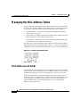
SNMP Network Management Platforms 4-6
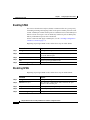
Using FTP to Access the MIB Files 4-7
Using SNMP to Access MIB Variables 4-7
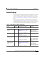
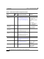
Default Settings 4-9
CHAPTER
5
Clustering Switches 5-1
Understanding Switch Clusters 5-2
Command Switch Characteristics 5-2
Standby Command Switch Characteristics 5-3
Candidate and Cluster Member Characteristics 5-3
Planning a Switch Cluster 5-4
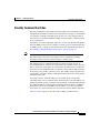
Automatic Discovery of Cluster Candidates 5-4
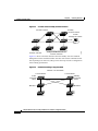
Standby Command Switches 5-5
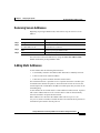
IP Addresses 5-8
Passwords 5-8
Host Names 5-10
SNMP Community Strings 5-10
Management VLAN 5-11
Network Port 5-12
NAT Commands 5-12
LRE Profiles 5-13
Availability of Switch-Specific Features in Switch Clusters 5-13
Catalyst 2900 Series XL and Catalyst 3500 Series XL Software Configuration Guide
vi
78-6511-05
Contents
Creating a Switch Cluster 5-13
Designating and Enabling a Command Switch 5-14
Adding and Removing Cluster Members 5-14
Designating and Enabling Standby Command Switches 5-17
Verifying a Switch Cluster 5-19
Displaying an Inventory of the Clustered Switches 5-19
Displaying Link Information 5-20
Using the CLI to Manage Switch Clusters 5-21
Using SNMP to Manage Switch Clusters 5-22
CHAPTER
6
Configuring the System 6-1
Changing IP Information 6-2
Manually Assigning and Removing Switch IP Information 6-2
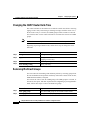
Using DHCP-Based Autoconfiguration 6-4
Understanding DHCP-Based Autoconfiguration 6-4
DHCP Client Request Process 6-5
Configuring the DHCP Server 6-6
Configuring the TFTP Server 6-7
Configuring the Domain Name and the DNS 6-8
Configuring the Relay Device 6-9
Obtaining Configuration Files 6-10
Example Configuration 6-12
Changing the Password 6-15
Setting the System Date and Time 6-17
Configuring Daylight Saving Time 6-17
Configuring the Network Time Protocol 6-17
Configuring the Switch as an NTP Client 6-17
Enabling NTP Authentication 6-18
Configuring the Switch for NTP Broadcast-Client Mode 6-18
Catalyst 2900 Series XL and Catalyst 3500 Series XL Software Configuration Guide
78-6511-05
vii
Contents
Configuring SNMP 6-18
Disabling and Enabling SNMP 6-18
Entering Community Strings 6-19
Adding Trap Managers 6-19
Configuring CDP 6-22
Configuring CDP for Extended Discovery 6-22
Configuring STP 6-24
Supported STP Instances 6-24
Using STP to Support Redundant Connectivity 6-25
Disabling STP 6-25
Accelerating Aging to Retain Connectivity 6-26
Configuring STP and UplinkFast in a Cascaded Cluster 6-26
Configuring Redundant Links By Using STP UplinkFast 6-28
Enabling STP UplinkFast 6-30
Configuring Cross-Stack UplinkFast 6-31
How CSUF Works 6-31
Events that Cause Fast Convergence 6-33
Limitations 6-35
Connecting the Stack Ports 6-35
Configuring Cross-Stack UplinkFast 6-37
Changing the STP Parameters for a VLAN 6-38
Changing the STP Implementation 6-39
Changing the Switch Priority 6-39
Changing the BPDU Message Interval 6-40
Changing the Hello BPDU Interval 6-40
Changing the Forwarding Delay Time 6-41
STP Port States 6-41
Enabling the Port Fast Feature 6-42
Changing the Path Cost 6-43
Changing the Port Priority 6-43
Configuring STP Root Guard 6-44
Catalyst 2900 Series XL and Catalyst 3500 Series XL Software Configuration Guide
viii
78-6511-05
Contents
Managing the ARP Table 6-45
Controlling IP Multicast Packets through CGMP 6-46
Enabling the Fast Leave Feature 6-47
Disabling the CGMP Fast Leave Feature 6-47
Changing the CGMP Router Hold-Time 6-48
Removing Multicast Groups 6-48
Configuring MVR 6-49
Using MVR in a Multicast Television Application 6-49
Configuration Guidelines and Limitations 6-51
Setting MVR Parameters 6-53
Configuring MVR 6-54
Managing the MAC Address Tables 6-56
MAC Addresses and VLANs 6-56
Changing the Address Aging Time 6-57
Removing Dynamic Address Entries 6-58
Adding Secure Addresses 6-58
Removing Secure Addresses 6-59
Adding Static Addresses 6-59
Removing Static Addresses 6-60
Configuring Static Addresses for EtherChannel Port Groups 6-61
Configuring TACACS+ 6-61
Configuring the TACACS+ Server Host 6-62
Configuring Login Authentication 6-64
Specifying TACACS+ Authorization for EXEC Access and Network
Services 6-65
Starting TACACS+ Accounting 6-66
Configuring a Switch for Local AAA 6-67
Catalyst 2900 Series XL and Catalyst 3500 Series XL Software Configuration Guide
78-6511-05
ix
Contents
CHAPTER
7
Configuring the Switch Ports 7-1
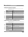
Changing the Port Speed and Duplex Mode 7-2
Connecting to Devices That Do Not Autonegotiate 7-2
Setting Speed and Duplex Parameters 7-3
Configuring Flow Control on Gigabit Ethernet Ports 7-3
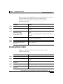
Configuring Flooding Controls 7-4
Enabling Storm Control 7-4
Disabling Storm Control 7-5
Blocking Flooded Traffic on a Port 7-6
Resuming Normal Forwarding on a Port 7-7
Enabling a Network Port 7-7
Disabling a Network Port 7-8
Configuring UniDirectional Link Detection 7-9
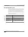
Creating EtherChannel Port Groups 7-10
Understanding EtherChannel Port Grouping 7-10
Port Group Restrictions on Static-Address Forwarding 7-11
Creating EtherChannel Port Groups 7-12
Configuring Protected Ports 7-13
Enabling Port Security 7-14
Defining the Maximum Secure Address Count 7-15
Enabling Port Security 7-15
Disabling Port Security 7-15
Enabling SPAN 7-16
Disabling SPAN 7-16
Configuring Voice Ports 7-17
Preparing a Port for a Cisco 7960 IP Phone Connection 7-18
Configuring a Port to Connect to a Cisco 7960 IP Phone 7-18
Overriding the CoS Priority of Incoming Frames 7-19
Configuring Voice Ports to Carry Voice and Data Traffic on Different
VLANs 7-20
Catalyst 2900 Series XL and Catalyst 3500 Series XL Software Configuration Guide
x
78-6511-05
Contents
Configuring Inline Power on the Catalyst 3524-PWR Ports 7-21
Configuring the LRE Ports 7-22
LRE Links and LRE Profiles 7-22
LRE Ethernet Links 7-25
Assigning a Public Profile to All LRE Ports 7-27
Assigning a Private Profile to an LRE Port 7-28
CHAPTER
8
Configuring VLANs 8-1
Overview 8-2
Management VLANs 8-4
Changing the Management VLAN for a New Switch 8-5
Changing the Management VLAN Through a Telnet Connection 8-6
Assigning VLAN Port Membership Modes 8-7
VLAN Membership Combinations 8-8
Assigning Static-Access Ports to a VLAN 8-10
Overlapping VLANs and Multi-VLAN Ports 8-11
Using VTP 8-12
The VTP Domain 8-13
VTP Modes and Mode Transitions 8-14
VTP Advertisements 8-15
VTP Version 2 8-16
VTP Pruning 8-17
VTP Configuration Guidelines 8-18
Domain Names 8-18
Passwords 8-18
Upgrading from Previous Software Releases 8-19
VTP Version 8-19
Default VTP Configuration 8-20
Catalyst 2900 Series XL and Catalyst 3500 Series XL Software Configuration Guide
78-6511-05
xi
Contents
Configuring VTP 8-20
Configuring VTP Server Mode 8-21
Configuring VTP Client Mode 8-22
Disabling VTP (VTP Transparent Mode) 8-23
Enabling VTP Version 2 8-24
Disabling VTP Version 2 8-25
Enabling VTP Pruning 8-25
Monitoring VTP 8-26
VLANs in the VTP Database 8-27
Token Ring VLANs 8-27
VLAN Configuration Guidelines 8-28
Default VLAN Configuration 8-28
Configuring VLANs in the VTP Database 8-32
Adding a VLAN 8-33
Modifying a VLAN 8-34
Deleting a VLAN from the Database 8-34
Assigning Static-Access Ports to a VLAN 8-35
How VLAN Trunks Work 8-36
IEEE 802.1Q Configuration Considerations 8-37
Trunks Interacting with Other Features 8-37
Configuring a Trunk Port 8-38
Disabling a Trunk Port 8-40
Defining the Allowed VLANs on a Trunk 8-40
Changing the Pruning-Eligible List 8-42
Configuring the Native VLAN for Untagged Traffic 8-43
Configuring 802.1p Class of Service 8-44
How Class of Service Works 8-44
Port Priority 8-44
Port Scheduling 8-45
Configuring the CoS Port Priorities 8-46
Catalyst 2900 Series XL and Catalyst 3500 Series XL Software Configuration Guide
xii
78-6511-05
Contents
Load Sharing Using STP 8-46
Load Sharing Using STP Port Priorities 8-47
Configuring STP Port Priorities and Load Sharing 8-48
Load Sharing Using STP Path Cost 8-50
How the VMPS Works 8-52
Dynamic Port VLAN Membership 8-53
VMPS Database Configuration File 8-54
VMPS Configuration Guidelines 8-56
Default VMPS Configuration 8-57
Configuring Dynamic VLAN Membership 8-57
Configuring Dynamic Ports on VMPS Clients 8-58
Reconfirming VLAN Memberships 8-59
Changing the Reconfirmation Interval 8-59
Changing the Retry Count 8-60
Administering and Monitoring the VMPS 8-60
Troubleshooting Dynamic Port VLAN Membership 8-61
Dynamic Port VLAN Membership Configuration Example 8-61
CHAPTER
9
Troubleshooting 9-1
Avoiding Configuration Conflicts 9-2
Avoiding Autonegotiation Mismatches 9-3
Troubleshooting LRE Port Configuration 9-4
Troubleshooting CMS Sessions 9-5
Determining Why a Switch Is Not Added to a Cluster 9-8
Copying Configuration Files to Troubleshoot Configuration Problems 9-9
Troubleshooting Switch Upgrades 9-10
Catalyst 2900 Series XL and Catalyst 3500 Series XL Software Configuration Guide
78-6511-05
xiii
Contents
Recovery Procedures 9-13
Recovering from Lost Member Connectivity 9-13
Recovering from a Command Switch Failure 9-14
Replacing a Failed Command Switch with a Cluster Member 9-15
Replacing a Failed Command Switch with Another Switch 9-19
Recovering from a Failed Command Switch Without HSRP 9-22
Recovering from a Lost or Forgotten Password 9-22
Recovering from Corrupted Software 9-25
APPENDIX
A
System Error Messages A-1
How to Read System Error Messages A-2
Error Message Traceback Reports A-4
Error Message and Recovery Procedures A-5
Chassis Message A-5
CMP Messages A-5
Environment Messages A-6
GigaStack Messages A-7
Link Message A-8
LRE Link Messages A-8
Module Message A-9
Port Security Messages A-9
RTD Messages A-10
Storm Control Messages A-11
INDEX
Catalyst 2900 Series XL and Catalyst 3500 Series XL Software Configuration Guide
xiv
78-6511-05
Preface
Audience
The Catalyst 2900 Series XL and Catalyst 3500 Series XL Software
Configuration Guide is for the network manager responsible for configuring the
Catalyst 2900 series XL and Catalyst 3500 series XL switches, hereafter referred
to as the switches. Before using this guide, you should be familiar with the
concepts and terminology of Ethernet and local area networking.
Purpose
This guide provides information about configuring and troubleshooting a switch
or switch clusters. This guide also provides information about configuring the
Cisco 575 Long-Reach Ethernet (LRE) customer premises equipment (CPE). It
includes descriptions of the management interface options and the features
supported by the switch software.
Use this guide in conjunction with other documents for the following topics:
•
Requirements—This guide assumes you have met the hardware and software
requirements and cluster compatibility requirements, as described in the
release notes.
•
Start up information—This guide assumes you have assigned switch IP
information and passwords by using the setup program, which is described in
the release notes.
Catalyst 2900 Series XL and Catalyst 3500 Series XL Software Configuration Guide
78-6511-05
xv
Preface
Purpose
•
Cluster Management Suite (CMS) information—This guide provides an
overview of the CMS web-based, switch management interface. For
information about CMS requirements and the procedures for browser and
plug-in configuration and accessing CMS, refer to the release notes. For CMS
field-level window descriptions and procedures, refer to the CMS online
help.
•
Cluster configuration—This guide provides information about planning for,
creating, and maintaining switch clusters. Because configuring switch
clusters is most easily performed through CMS, this guide does not provide
the command-line interface (CLI) procedures. For the cluster commands,
refer to the Catalyst 2900 Series XL and Catalyst 3500 Series XL Command
Reference.
•
CLI command information—This guide provides an overview for using the
CLI. For complete syntax and usage information about the commands that
have been specifically created or changed for the Catalyst 2900 XL or
Catalyst 3500 XL switches, refer to the Catalyst 2900 Series XL and
Catalyst 3500 Series XL Command Reference.
Note
This guide does not repeat the concepts and CLI procedures provided
in the standard Cisco IOS Release 12.0 documentation. For switch
features that use standard Cisco IOS Release 12.0 commands, refer to
the Cisco IOS Release 12.0 documentation on Cisco.com for
additional information and CLI procedures.
Catalyst 2900 Series XL and Catalyst 3500 Series XL Software Configuration Guide
xvi
78-6511-05
Preface
Organization
Organization
The organization of this guide is as follows:
Chapter 1, “Overview,” lists the software features of this release and provides
examples of how the switch can be deployed in a network.
Chapter 2, “Getting Started with CMS,” describes the Cluster Management Suite
(CMS) web-based, switch management interface. Refer to the release notes for
the procedures for configuring your web browser and accessing CMS. Refer to the
online help for field-level descriptions of all CMS windows and procedures for
using the CMS windows.
Chapter 3, “Getting Started with the CLI,” describes the basics for using the Cisco
IOS CLI.
Chapter 4, “General Switch Administration,” includes the switch-configuration
default settings and information about software releases, accessing the
management interfaces, and using Simple Network Management Protocol
(SNMP).
Chapter 5, “Clustering Switches,” describes switch clusters and the
considerations for creating and maintaining them. The online help provides the
CMS procedures for configuring switch clusters. Cluster commands are described
in the Catalyst 2900 Series XL and Catalyst 3500 Series XL Command Reference.
Chapter 6, “Configuring the System,” provides the considerations and CLI
procedures for configuring switch-wide settings. The online help provides the
CMS procedures for configuring switch-wide settings.
Chapter 7, “Configuring the Switch Ports,” provides the considerations and CLI
procedures for configuring the switch ports. The online help provides the CMS
procedures for configuring the switch ports.
Chapter 8, “Configuring VLANs,” provides the considerations and CLI
procedures for configuring VLANs. The online help provides the CMS
procedures for configuring VLANs.
Chapter 9, “Troubleshooting,” provides information about avoiding and resolving
problems that might arise when you configure and maintain the switch.
Appendix A, “System Error Messages,” lists the IOS system error messages for
the switch.
Catalyst 2900 Series XL and Catalyst 3500 Series XL Software Configuration Guide
78-6511-05
xvii
Preface
Conventions
Conventions
This guide uses the following conventions to convey instructions and
information:
Command descriptions use these conventions:
•
Commands and keywords are in boldface text.
•
Arguments for which you supply values are in italic.
•
Square brackets ([ ]) indicate optional elements.
•
Braces ({ }) group required choices, and vertical bars ( | ) separate the
alternative elements.
•
Braces and vertical bars within square brackets ([{ | }]) indicate a required
choice within an optional element.
Interactive examples use these conventions:
•
Terminal sessions and system displays are in screen font.
•
Information you enter is in boldface
•
Nonprinting characters, such as passwords or tabs, are in angle brackets (< >).
screen
font.
Notes, cautions, and tips use the following conventions and symbols:
Note
Means reader take note. Notes contain helpful suggestions or references to
materials not contained in this manual.
Caution
Means reader be careful. In this situation, you might do something that could
result in equipment damage or loss of data.
Tips
Means the following will help you solve a problem. The tips information might
not be troubleshooting or even an action, but could be useful information.
Catalyst 2900 Series XL and Catalyst 3500 Series XL Software Configuration Guide
xviii
78-6511-05
Preface
Related Publications
Related Publications
You can order printed copies of documents with a DOC-xxxxxx= number. See the
“Ordering Documentation” section on page xxi.
The following publications provide more information about the switches:
•
Release Notes for the Catalyst 2900 Series XL and Catalyst 3500 Series XL
Cisco IOS Release 12.0(5)WC(1) (not orderable but is available on
Cisco.com)
•
Cluster Management Suite (CMS) online help
•
Catalyst 2900 XL and Catalyst 3500 XL Documentation CD (not orderable)
Note
This product-specific CD contains only the Catalyst 2900 XL and
Catalyst 3500 XL switch documents and related hardware documents.
This CD is not the same as the Cisco Documentation CD-ROM, which
contains the documentation for all Cisco products and is shipped with
all Cisco products.
The Catalyst 2900 XL and Catalyst 3500 XL Documentation CD is shipped
with the switch and has the following publications:
– This Catalyst 2900 Series XL and Catalyst 3500 Series XL Software
Configuration Guide, Cisco IOS Release 12.0(5)WC(1)
(order number DOC-786511=)
– Catalyst 2900 Series XL and Catalyst 3500 Series XL Command
Reference, Cisco IOS Release 12.0(5)WC(1)
(order number DOC-7812155=)
– Catalyst 2900 Series XL Hardware Installation Guide
(order number DOC-786461=)
– Catalyst 3500 Series XL Hardware Installation Guide
(order number DOC-786456=)
– Catalyst 2900 Series XL Modules Installation Guide
(order number DOC-CAT2900-IG=)
– Catalyst 2900 Series XL ATM Modules Installation and Configuration
Guide (order number DOC-785472=)
Catalyst 2900 Series XL and Catalyst 3500 Series XL Software Configuration Guide
78-6511-05
xix
Preface
Obtaining Documentation
– 1000BASE-T Gigabit Interface Converter Installation Note
(not orderable but is available on Cisco.com)
– Catalyst GigaStack Gigabit Interface Converter Hardware Installation
Guide (order number DOC-786460=)
– Cisco 575 LRE CPE Hardware Installation Guide
(order number DOC-7811469=)
Obtaining Documentation
The following sections provide sources for obtaining documentation from Cisco
Systems.
World Wide Web
You can access the most current Cisco documentation on the World Wide Web at
the following sites:
•
http://www.cisco.com
•
http://www-china.cisco.com
•
http://www-europe.cisco.com
Cisco Documentation CD-ROM
Cisco documentation and additional literature are available in a CD-ROM
package, which ships with your product. The Cisco Documentation CD-ROM is
updated monthly and may be more current than printed documentation. The
CD-ROM package is available as a single unit or as an annual subscription.
Note
This CD contains the documentation for all Cisco products and is
shipped with all Cisco products. This CD is not the same as the
Catalyst 2900 XL and Catalyst 3500 XL Documentation CD, which
contains only the Catalyst 2900 XL and Catalyst 3500 XL switch
documents and related hardware documents.
Catalyst 2900 Series XL and Catalyst 3500 Series XL Software Configuration Guide
xx
78-6511-05
Preface
Obtaining Documentation
Ordering Documentation
Cisco documentation is available in the following ways:
•
Registered Cisco Direct Customers can order Cisco Product documentation
from the Networking Products MarketPlace:
http://www.cisco.com/cgi-bin/order/order_root.pl
•
Registered Cisco.com users can order the Documentation CD-ROM through
the online Subscription Store:
http://www.cisco.com/go/subscription
•
Nonregistered CCO users can order documentation through a local account
representative by calling Cisco corporate headquarters (California, USA) at
408 526-7208 or, in North America, by calling 800 553-NETS(6387).
Documentation Feedback
If you are reading Cisco product documentation on the World Wide Web, you can
send us your comments by completing the online survey. When you display the
document listing for this platform, click Give Us Your Feedback. If you are using
the product-specific CD and you are connected to the Internet, click the
pencil-and-paper icon in the toolbar to display the survey. After you display the
survey, select the manual that you wish to comment on. Click Submit to send your
comments to the Cisco documentation group.
You can e-mail your comments to [email protected].
To submit your comments by mail, for your convenience many documents contain
a response card behind the front cover. Otherwise, you can mail your comments
to the following address:
Cisco Systems, Inc.
Document Resource Connection
170 West Tasman Drive
San Jose, CA 95134-9883
We appreciate your comments.
Catalyst 2900 Series XL and Catalyst 3500 Series XL Software Configuration Guide
78-6511-05
xxi
Preface
Obtaining Technical Assistance
Obtaining Technical Assistance
Cisco provides Cisco.com as a starting point for all technical assistance.
Customers and partners can obtain documentation, troubleshooting tips, and
sample configurations from online tools. For Cisco.com registered users,
additional troubleshooting tools are available from the TAC website.
Cisco.com
Cisco.com is the foundation of a suite of interactive, networked services that
provides immediate, open access to Cisco information and resources at anytime,
from anywhere in the world. This highly integrated Internet application is a
powerful, easy-to-use tool for doing business with Cisco.
Cisco.com provides a broad range of features and services to help customers and
partners streamline business processes and improve productivity. Through
Cisco.com, you can find information about Cisco and our networking solutions,
services, and programs. In addition, you can resolve technical issues with online
technical support, download and test software packages, and order Cisco learning
materials and merchandise. Valuable online skill assessment, training, and
certification programs are also available.
Customers and partners can self-register on Cisco.com to obtain additional
personalized information and services. Registered users can order products, check
on the status of an order, access technical support, and view benefits specific to
their relationships with Cisco.
To access Cisco.com, go to the following website:
http://www.cisco.com
Technical Assistance Center
The Cisco TAC website is available to all customers who need technical
assistance with a Cisco product or technology that is under warranty or covered
by a maintenance contract.
Catalyst 2900 Series XL and Catalyst 3500 Series XL Software Configuration Guide
xxii
78-6511-05
Preface
Obtaining Technical Assistance
Contacting TAC by Using the Cisco TAC Website
If you have a priority level 3 (P3) or priority level 4 (P4) problem, contact TAC
by going to the TAC website:
http://www.cisco.com/tac
P3 and P4 level problems are defined as follows:
•
P3—Your network performance is degraded. Network functionality is
noticeably impaired, but most business operations continue.
•
P4—You need information or assistance on Cisco product capabilities,
product installation, or basic product configuration.
In each of the above cases, use the Cisco TAC website to quickly find answers to
your questions.
To register for Cisco.com, go to the following website:
http://www.cisco.com/register/
If you cannot resolve your technical issue by using the TAC online resources,
Cisco.com registered users can open a case online by using the TAC Case Open
tool at the following website:
http://www.cisco.com/tac/caseopen
Contacting TAC by Telephone
If you have a priority level 1 (P1) or priority level 2 (P2) problem, contact TAC
by telephone and immediately open a case. To obtain a directory of toll-free
numbers for your country, go to the following website:
http://www.cisco.com/warp/public/687/Directory/DirTAC.shtml
P1 and P2 level problems are defined as follows:
•
P1—Your production network is down, causing a critical impact to business
operations if service is not restored quickly. No workaround is available.
•
P2—Your production network is severely degraded, affecting significant
aspects of your business operations. No workaround is available.
Catalyst 2900 Series XL and Catalyst 3500 Series XL Software Configuration Guide
78-6511-05
xxiii
Preface
Obtaining Technical Assistance
Catalyst 2900 Series XL and Catalyst 3500 Series XL Software Configuration Guide
xxiv
78-6511-05
1
C H A P T E R
Overview
This chapter provides the following topics about the Catalyst 2900 XL and
Catalyst 3500 XL switch software:
•
Features
•
Management options
•
Examples of the Catalyst 2900 XL and Catalyst 3500 XL switches in
different network topologies
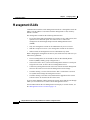
Features
The Catalyst 2900 XL and Catalyst 3500 XL software supports the switches and
modules listed in the Release Notes for the Catalyst 2900 Series XL and
Catalyst 3500 Series XL Cisco IOS Release 12.0(5)WC(1). This software also
supports the Cisco 575 Long-Reach Ethernet (LRE) customer premises
equipment (CPE).
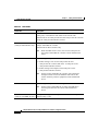
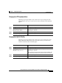
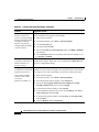
Table 1-1 describes the features supported in this release.
Note
Table 4-2 on page 4-9 lists the defaults for all key features. It also includes
references to where you can find additional information about each feature.
Catalyst 2900 Series XL and Catalyst 3500 Series XL Software Configuration Guide
78-6511-05
1-1
Chapter 1
Overview
Features
Table 1-1
Features
Ease of Use and Ease of Deployment
•
Cluster Management Suite (CMS) software for simplified switch and switch cluster management
through a web browser, such as Netscape Communicator or Microsoft Internet Explorer, from
anywhere in your intranet
•
Switch clustering technology, in conjunction with CMS, for
– Unified configuration, monitoring, authentication, and software upgrade of multiple switches
(refer to the release notes for a list of eligible cluster members).
– Automatic discovery of candidate switches and creation of clusters of up to 16 switches that
can be managed through a single IP address.
– Extended discovery of cluster candidates that are not directly connected to the command
switch.
•
Note
Hot Standby Router Protocol (HSRP) for command-switch redundancy
See the “Advantages of Using CMS and Clustering Switches” section on page 1-8. Refer
to the release notes for the CMS and cluster hardware, software, and browser requirements.
Performance
•
Autosensing of speed on the 10/100 ports and autonegotiation of duplex mode on all switch ports
for optimizing bandwidth
•
IEEE 802.3x flow control on 100-Mbps and Gigabit ports operating in full-duplex mode
•
Fast EtherChannel and Gigabit EtherChannel for enhanced fault tolerance and for providing up to
4 Gbps of bandwidth between switches, routers, and servers
•
Per-port broadcast storm control for preventing faulty end stations from degrading overall system
performance with broadcast storms
•
Cisco Group Management Protocol (CGMP) for limiting multicast traffic to specified end stations
and reducing overall network traffic
•
CGMP Fast Leave for accelerating the removal of unused CGMP groups to reduce superfluous
traffic on the network
•
Multicast VLAN registration (MVR) to continuously send multicast streams in a multicast
VLAN, but to isolate the streams from subscriber VLANs for bandwidth and security reasons
•
Protected port (private VLAN edge port) option for restricting the forwarding of traffic to
designated ports on the same switch
Catalyst 2900 Series XL and Catalyst 3500 Series XL Software Configuration Guide
1-2
78-6511-05
Chapter 1
Overview
Features
Table 1-1
Features (continued)
Manageability
•
Dynamic Host Configuration Protocol (DHCP)-based autoconfiguration for automatically
configuring the switch during startup with IP address information and a configuration file that it
receives during DHCP-based autoconfiguration
Note
DHCP replaces the Bootstrap Protocol (BOOTP) feature autoconfiguration to ensure
retrieval of configuration files by unicast TFTP messages. BOOTP is available in earlier
software releases for this switch.
•
Directed unicast requests to a Domain Name System (DNS) server for identifying a switch
through its IP address and its corresponding host name
•
Address Resolution Protocol (ARP) for identifying a switch through its IP address and its
corresponding MAC address
•
Cisco Discovery Protocol (CDP) versions 1 and 2 for network topology discovery and mapping
between the switch and other Cisco devices on the network
•
Network Time Protocol (NTP) for providing a consistent timestamp to all switches from an
external source
•
Directed unicast requests to a Trivial File Transfer Protocol (TFTP) server for administering
software upgrades from a TFTP server
•
Default configuration stored in Flash memory to ensure that the switch can be connected to a
network and can forward traffic with minimal user intervention
•
In-band management access through a CMS web-based session
•
In-band management access through up to 16 simultaneous Telnet connections for multiple
command-line interface (CLI)-based sessions over the network
•
In-band management access through Simple Network Management Protocol (SNMP) set and get
requests
•
Out-of-band management access through the switch console port to a directly-attached terminal
or to a remote terminal through a serial connection and a modem
Note
For additional descriptions of the management interfaces, see the “Management Options”
section on page 1-7.
Catalyst 2900 Series XL and Catalyst 3500 Series XL Software Configuration Guide
78-6511-05
1-3
Chapter 1
Overview
Features
Table 1-1
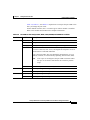
Features (continued)
Redundancy
•
HSRP for command switch redundancy
•
UniDirectional link detection (UDLD) on all Ethernet ports for detecting and disabling
unidirectional links on fiber-optic interfaces caused by incorrect fiber-optic wiring or port faults
•
IEEE 802.1d Spanning Tree Protocol (STP) for redundant backbone connections and loop-free
networks. STP has these features
– Per-VLAN Spanning Tree (PVST) for balancing load across virtual LANs (VLANs)
– Port Fast mode for eliminating forward delay by enabling a port to immediately change from
a blocking state to a forwarding state
– UplinkFast, Cross-Stack UplinkFast, and BackboneFast for fast convergence after a
spanning-tree topology change and for achieving load balancing between redundant uplinks,
including Gigabit uplinks and cross-stack Gigabit uplinks
– STP root guard for preventing switches outside the core of the network from becoming the
STP root
Note
Depending on the model, a switch can support up to 64 or 250 instances of STP (see
Table 8-1 on page 8-3).
VLAN Support
•
Note
Depending on the switch model, up to 64 or 250 port-based VLANs are supported for assigning
users to VLANs associated with appropriate network resources, traffic patterns, and bandwidth
For information about the maximum number of VLANs supported on each
Catalyst 2900 XL and Catalyst 3500 XL switch, see the Table 8-1 on page 8-3.
•
Inter-Switch Link (ISL) and IEEE 802.1Q trunking protocol on all ports for simplified network
moves, adds, and changes; better management and control of broadcast and multicast traffic; and
improved network security by establishing VLAN groups for high-security users and network
resources
•
VLAN Membership Policy Server (VMPS) for dynamic VLAN membership
•
VLAN Trunk Protocol (VTP) pruning for reducing network traffic by restricting flooded traffic
to links destined for stations receiving the traffic
Catalyst 2900 Series XL and Catalyst 3500 Series XL Software Configuration Guide
1-4
78-6511-05
Chapter 1
Overview
Features
Table 1-1
Features (continued)
Quality of Service and Class of Service
•
IEEE 802.1p class of service (CoS) with two priority queues on the 10/100 and LRE switch ports
and eight priority queues on the Gigabit ports for prioritizing mission-critical and time-sensitive
traffic from data, voice, and telephony applications
•
Voice VLAN (VVID) for creating subnets for voice traffic from Cisco IP Phones
Security
•
Password-protected access (read-only and read-write access) to management interfaces (CMS and
CLI) for protection against unauthorized configuration changes
•
Multilevel security for a choice of security level, notification, and resulting actions
•
Dynamic address learning for enhanced security
•
MAC-based port-level security for restricting the use of a switch port to a specific group of source
addresses and preventing switch access from unauthorized stations
•
Terminal Access Controller Access Control System Plus (TACACS+), a proprietary feature for
managing network security through a TACACS server
Monitoring
•
Switch LEDs that provide visual management of port- and switch-level status
•
Switch Port Analyzer (SPAN) for complete traffic monitoring on any port
•
Four groups (history, statistics, alarm, and events) of embedded remote monitoring (RMON)
agents for network monitoring and traffic analysis
•
Syslog facility for logging system messages about authentication or authorization errors, resource
issues, and time-out events
Catalyst 2900 Series XL and Catalyst 3500 Series XL Software Configuration Guide
78-6511-05
1-5
Chapter 1
Overview
Features
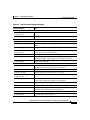
Table 1-1
Features (continued)
Catalyst 2912 LRE and Catalyst 2924 LRE XL Switch-Specific Support
•
Long-Reach Ethernet (LRE) technology for
– Data and voice transmission through existing telephone lines (categorized and
noncategorized unshielded twisted-pair cable) in multidwelling or tenant buildings.
– Up to 15 Mbps of bandwidth to remote Ethernet devices at distances of up to 4921 ft
(1500 m) on each switch LRE port.
– Compliance with American National Standards Institute (ANSI) and European
Telecommunication Standards Institute (ETSI) standards for spectral-mode compatibility
with asymmetric digital subscriber line (ADSL), Integrated Services Digital Network
(ISDN), and digital telephone networks.
– Configuration and monitoring of connections between
•
Switch LRE ports and the Ethernet ports on remote LRE customer premises equipment
(CPE) devices, such as the Cisco 575 LRE CPE.
•
CPE Ethernet ports and remote Ethernet devices, such as a PC.
– Support for connecting to the Public Switched Telephone Network (PSTN) through plain old
telephone service (POTS) splitters such as the Cisco LRE 48 POTS Splitter
(PS-1M-LRE-48).
For information about the Cisco 575 LRE CPE, refer to the Cisco 575 LRE CPE Hardware
Installation Guide. For information about the nonhomologated Cisco LRE 48 POTS Splitter
(PS-1M-LRE-48), refer to the Cisco LRE 48 POTS Splitter Installation Note.
Catalyst 3524-PWR XL Switch-Specific Support
•
Ability to provide inline power to Cisco IP Phones from all 24 10/100 Ethernet ports
•
Autodetection and control of inline phone power on a per-port basis on all 10/100 ports
•
Fan-fault and over-temperature detection through Visual Switch Manager (VSM)
Catalyst 2900 Series XL and Catalyst 3500 Series XL Software Configuration Guide
1-6
78-6511-05
Chapter 1
Overview
Management Options
Management Options
The Catalyst 2900 XL and Catalyst 3500 XL switches are designed for
plug-and-play operation: you only need to assign basic IP information to the
switch and connect it to the other devices in your network. If you have specific
network needs, you can configure and monitor the switch—on an individual basis
or as part of a switch cluster—through its various management interfaces.
This section discusses these topics:
•
Interface options for managing the switches
•
Advantages of clustering switches and using CMS
Management Interface Options
You can configure and monitor individual switches and switch clusters by using
the following interfaces:
•
CMS—CMS is a graphical user interface that can be launched from anywhere
in your network through a web browser such as Netscape Communicator or
Microsoft Internet Explorer. CMS is already installed on the switch. Using
CMS, you can fully configure and monitor a standalone switch, a specific
cluster member, or an entire switch cluster. You can also display network
topologies to gather link information and to display switch images to modify
switch- and port-level settings.
For more information about CMS, see Chapter 2, “Getting Started with
CMS.”
•
CLI—The switch IOS CLI software is enhanced to support
desktop-switching features. You can fully configure and monitor the switch
and switch cluster members from the CLI. You can access the CLI either by
connecting your management station directly to the switch console port or by
using Telnet from a remote management station.
For more information about the CLI, see Chapter 3, “Getting Started with the
CLI.”
Catalyst 2900 Series XL and Catalyst 3500 Series XL Software Configuration Guide
78-6511-05
1-7
Chapter 1
Overview
Management Options
•
SNMP—SNMP provides a means to monitor and control the switch and
switch cluster members. You can manage switch configuration settings,
performance, security, and collect statistics by using SNMP management
applications such as CiscoWorks2000 LAN Management Suite (LMS) and
HP OpenView.
You can manage the switch from an SNMP-compatible management station
that is running platforms such as HP OpenView or SunNet Manager. The
switch supports a comprehensive set of MIB extensions and four RMON
groups.
For more information about using SNMP, see the “SNMP Network
Management Platforms” section on page 4-6.
Advantages of Using CMS and Clustering Switches
Using CMS and switch clusters can simplify and minimize your configuration and
monitoring tasks. You can use Cisco switch clustering technology to manage up
to 16 interconnected supported Catalyst switches through one IP address as if they
were a single entity. This can conserve IP addresses if you have a limited number
of them. CMS is the easiest interface to use and makes switch and switch cluster
management accessible to authorized users from any PC on your network.
By using switch clusters and CMS, you can
•
Manage and monitor interconnected Catalyst switches (refer to the release
notes for a list of supported switches), regardless of their geographic
proximity and interconnection media, including Ethernet, Fast Ethernet, Fast
EtherChannel, Cisco GigaStack Gigabit Interface Converter (GBIC), Gigabit
Ethernet, and Gigabit EtherChannel connections.
•
Accomplish multiple configuration tasks from a single CMS window without
needing to remember CLI commands to accomplish specific tasks.
Catalyst 2900 Series XL and Catalyst 3500 Series XL Software Configuration Guide
1-8
78-6511-05
Chapter 1
Overview
Management Options
•
Apply actions from CMS to multiple ports and multiple switches at the same
time to avoid re-entering the same commands for each individual port or
switch. Here are some examples of globally setting and managing multiple
ports and switches:
– Port configuration such as speed and duplex settings
– Port and console port security
– NTP, STP, VLAN, and quality of service (QoS) configuration
– Inventory and statistic reporting and link- and switch-level monitoring
and troubleshooting
– Group software upgrade
•
View a topology of interconnected devices to identify existing switch clusters
and eligible switches that can join a cluster. You can also use the topology to
quickly identify link information between switches.
•
Monitor real-time status of a switch or multiple switches from the LEDs on
the front-panel images. The system, redundant power system (RPS), and port
LED colors on the images are similar to those used on the physical LEDs
themselves.
For more information about CMS, see Chapter 2, “Getting Started with CMS.”
For more information about switch clusters, see Chapter 5, “Clustering
Switches.”
Catalyst 2900 Series XL and Catalyst 3500 Series XL Software Configuration Guide
78-6511-05
1-9
Chapter 1
Overview
Network Configuration Examples
Network Configuration Examples
This section provides network configuration concepts and includes examples of
using the switch to create dedicated network segments and interconnecting the
segments through Fast Ethernet and Gigabit Ethernet connections.
Design Concepts for Using the Switch
As your network users compete for network bandwidth, it takes longer to send and
receive data. When you configure your network, consider the bandwidth required
by your network users and the relative priority of the network applications they
use.
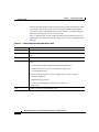
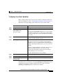
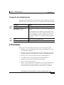
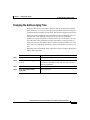
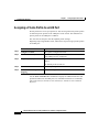
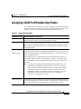
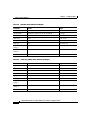
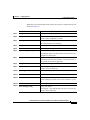
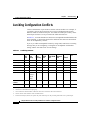
Table 1-2 describes what can cause network performance to degrade and
describes how you can configure your network to increase the bandwidth
available to your network users.
Table 1-2
Increasing Network Performance
Network Demands
Too many users on a single network
segment and a growing number of
users accessing the Internet
•
Increased power of new PCs,
workstations, and servers
•
High demand from networked
applications (such as e-mail with
large attached files) and from
bandwidth-intensive applications
(such as multimedia)
Suggested Design Methods
•
Create smaller network segments so that fewer users share
the bandwidth, and use VLANs and IP subnets to place the
network resources in the same logical network as the users
who access those resources most.
•
Use full-duplex operation between the switch and its
connected workstations.
•
Connect global resources—such as servers and routers to
which network users require equal access—directly to the
Fast Ethernet or Gigabit Ethernet switch ports so that they
have their own Fast Ethernet or Gigabit Ethernet segment.
•
Use the Fast EtherChannel or Gigabit EtherChannel feature
between the switch and its connected servers and routers.
Catalyst 2900 Series XL and Catalyst 3500 Series XL Software Configuration Guide
1-10
78-6511-05
Chapter 1
Overview
Network Configuration Examples
Bandwidth alone is not the only consideration when designing your network. As
your network traffic profiles evolve, consider providing network services that can
support applications such as voice and data integration and security.
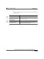
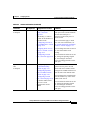
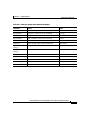
Table 1-3 describes some network demands and how you can meet those
demands.
Table 1-3
Providing Network Services
Network Demands
Suggested Design Methods
High demand for multimedia support
•
Use CGMP and MVR to efficiently forward multicast
traffic.
High demand for protecting
mission-critical applications
•
Use VLANs and protected ports to provide security and
port isolation.
•
Use VLAN trunks, Cross-Stack UplinkFast, and
BackboneFast for traffic-load balancing on the uplink
ports so that the uplink port with a lower relative port cost
is selected to carry the VLAN traffic.
•
Use QoS to prioritize applications such as IP telephony
during congestion and to help control both delay and jitter
within the network.
•
Use switches that support at least two queues per port to
prioritize voice and data traffic as either high- or
low-priority, based on 802.1p/Q.
•
Use VVIDs to provide a separate VLAN for voice traffic.
•
Use the Catalyst 2900 LRE XL switches to provide up to
15 Mb of IP connectivity over existing infrastructure
(existing telephone lines).
An evolving demand for IP telephony
A growing demand for using existing
infrastructure to transport data and
voice from a home or office to the
Internet or an intranet at higher speeds
Catalyst 2900 Series XL and Catalyst 3500 Series XL Software Configuration Guide
78-6511-05
1-11
Chapter 1
Overview
Network Configuration Examples
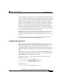
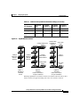
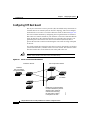
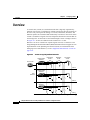
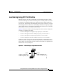
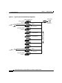
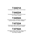
Figure 1-1 shows three configuration examples for using the Catalyst 2900 XL
and Catalyst 3500 XL switches to create the following:
•
Cost-effective wiring closet—A cost-effective way to connect many users to
the wiring closet is to connect up to nine Catalyst 2900 and Catalyst 3500 XL
switches through GigaStack GBIC connections. When you use a stack of
Catalyst 3548 XL switches, you can connect up to 432 users. To preserve
switch connectivity if one switch in the stack fails, connect the bottom switch
to the top switch to create a GigaStack loopback and enable Cross-Stack
UplinkFast on the cross-stack Gigabit uplinks.
You can create backup paths by using Fast Ethernet, Gigabit, or Fast
EtherChannel, or Gigabit EtherChannel links. Using Gigabit modules on two
of the switches, you can have redundant uplink connections to a Gigabit
backbone switch such as the Catalyst 3508G XL switch. If one of the
redundant connections fails, the other can serve as a backup path. You can
configure the stack members and the Catalyst 3508G XL switch as a switch
cluster to manage them through a single IP address.
•
High-performance workgroup—For users who require high-speed access to
network resources, use Gigabit modules to connect the switches directly to a
backbone switch in a star configuration. Each switch in this configuration
provides users a dedicated 1-Gbps connection to network resources in the
backbone. Compare this with the switches in a GigaStack configuration,
where the 1-Gbps connection is shared among the switches. Using the
following Gigabit modules also provides flexibility in media and distance
options:
– 1000BASE-SX GBIC: fiber connections of up to 1804 ft (550 m)
– 1000BASE-LX/LH GBIC: fiber connections of up to 32,808 ft (10 km)
– 1000BASE-ZX GBIC: fiber connections of up to 328,084 ft (100 km)
– 1000BASE-T GBIC: copper connections of up to 328 ft (100 m)
– Catalyst 2900 XL 1000BASE-T: copper connections of up to 328 ft
(100 m)
•
Redundant Gigabit backbone—Using HSRP, you can create backup paths
between Catalyst 4908G-L3 switches. To enhance network reliability and
load balancing for different VLANs and subnets, you can connect the
Catalyst 2900 XL and Catalyst 3500 XL switches, again in a star
configuration, to two backbone switches. If one of the backbone switches
fails, the second backbone switch preserves connectivity between the
switches and network resources.
Catalyst 2900 Series XL and Catalyst 3500 Series XL Software Configuration Guide
1-12
78-6511-05
Chapter 1
Overview
Network Configuration Examples
Figure 1-1
Example Configurations
Catalyst 3548 XL switch
Catalyst 2900 XL
and Catalyst 3500 XL
GigaStack cluster
Cost-Effective
Wiring Closet
Catalyst 3508 XL or 4908G-L3 switch
High-Performance
Workgroup
Catalyst 2900 XL and
Catalyst 3500 XL cluster
Catalyst 4908G-L3 switch
Catalyst 4908G-L3 switch
1-Gbps HSRP
Catalyst 2900 XL and
Catalyst 3500 XL cluster
54568
Redundant Gigabit
Backbone
Catalyst 2900 Series XL and Catalyst 3500 Series XL Software Configuration Guide
78-6511-05
1-13
Chapter 1
Overview
Network Configuration Examples
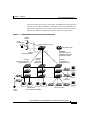
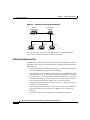
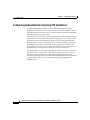
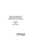
Small to Medium-Sized Network Configuration
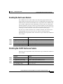
Figure 1-2 shows a configuration for a network that has up to 250 users. Users in
this network require e-mail, file-sharing, database, and Internet access.
You optimize network performance by placing workstations on the same logical
segment as the servers they access most often. This divides the network into
smaller segments (or workgroups) and reduces the amount of traffic that travels
over a network backbone, thereby increasing the bandwidth available to each user
and improving server response time.
A network backbone is a high-bandwidth connection (such as Fast Ethernet or
Gigabit Ethernet) that interconnects segments and network resources. It is required
if numerous segments require access to the servers. The Catalyst 2900 XL and
Catalyst 3500 XL switches in this network are connected through a GigaStack
GBIC on each switch to form a 1-Gbps network backbone. This GigaStack can
also be configured as a switch cluster, with primary and secondary command
switches for redundant cluster management.
Workstations are connected directly to the 10/100 switch ports for their own
10- or 100-Mbps access to network resources (such as web and mail servers).
When a workstation is configured for full-duplex operation, it receives up to
200 Mbps of dedicated bandwidth from the switch.
Servers are connected to the Gigabit module ports on the switches, allowing
1-Gbps throughput to users when needed. When the switch and server ports are
configured for full-duplex operation, the links provide 2 Gbps of bandwidth. For
networks that do not require Gigabit performance from a server, connect the
server to a Fast Ethernet or Fast EtherChannel switch port.
Connecting a router to a Fast Ethernet switch port provides multiple,
simultaneous access to the Internet through one line.
Catalyst 2900 Series XL and Catalyst 3500 Series XL Software Configuration Guide
1-14
78-6511-05
Chapter 1
Overview
Network Configuration Examples
Figure 1-2
Small to Medium-Sized Network Configuration
Cisco 2600 router
100 Mbps
(200 Mbps full duplex)
Gigabit
server
1 Gbps
(2 Gbps full duplex)
Catalyst 2900 XL
and Catalyst 3500 XL
GigaStack cluster
Gigabit
server
Single workstations
54569
10/100 Mbps
(20/200 Mbps full duplex)
Catalyst 2900 Series XL and Catalyst 3500 Series XL Software Configuration Guide
78-6511-05
1-15
Chapter 1
Overview
Network Configuration Examples
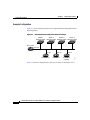
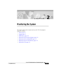
Collapsed Backbone and Switch Cluster Configuration
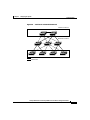
Figure 1-3 shows a configuration for a network of approximately 500 employees.
This network uses a collapsed backbone and switch clusters. A collapsed
backbone has high-bandwidth uplinks from all segments and subnetworks to a
single device, such as a Gigabit switch, which serves as a single point for
monitoring and controlling the network. You can use a Catalyst 4908G-L3 switch,
as shown, or a Catalyst 3508G XL switch to create a Gigabit backbone. A
Catalyst 4908G-L3 backbone switch provides the benefits of inter-VLAN routing
and allows the router to focus on WAN access.
The workgroups are created by clustering all the Catalyst switches except the
Catalyst 4908G-L3 switch. Using CMS and Cisco switch clustering technology,
you can group the switches into multiple clusters, as shown, or into a single
cluster. You can manage a cluster through the IP address of its active and standby
command switches, regardless of the geographic location of the cluster members.
This network uses VLANs to segment the network logically into well-defined
broadcast groups and for security management. Data and multimedia traffic are
configured on the same VLAN. Voice traffic from the Cisco IP Phones are
configured on separate VVIDs. You can have up to four VVIDs per wiring closet.
If data, multimedia, and voice traffic are assigned to the same VLAN, only
one VLAN can be configured per wiring closet. For any switch port connected to
Cisco IP Phones, 802.1p/Q QoS gives forwarding priority to voice traffic over
data traffic.
Grouping servers in a centralized location provides benefits such as security and
easier maintenance. The Gigabit connections to a server farm provide the
workgroups full access to the network resources (such as a call-processing server
running Cisco CallManager software, a DHCP server, or an IP/TV multicast
server).
Cisco IP Phones are connected—using standard straight-through, twisted-pair
cable with RJ-45 connectors—to the 10/100 inline-power ports on the
Catalyst 3524-PWR XL switches and to the 10/100 ports on the
Catalyst 2900 XL and Catalyst 3500 XL switches. These multiservice switch
ports automatically detect if an IP phone is connected. Cisco CallManager
controls call processing, routing, and IP phone features and configuration. Users
with workstations running Cisco SoftPhone software can place, receive, and
control calls from their PCs. Using Cisco IP Phones, Cisco CallManager
software, and Cisco SoftPhone software integrates telephony and IP networks,
where the IP network supports both voice and data.
Catalyst 2900 Series XL and Catalyst 3500 Series XL Software Configuration Guide
1-16
78-6511-05
Chapter 1
Overview
Network Configuration Examples
Each 10/100 inline-power port on the Catalyst 3524-PWR XL switches provides
–48 VDC power to the Cisco IP Phone. The IP phone can receive redundant power
when it also is connected to an AC power source. IP phones not connected to the
Catalyst 3524-PWR XL switches receive power from an AC power source.
Figure 1-3
Collapsed Backbone and Switch Cluster Configuration
Gigabit
servers
Cisco
CallManager
Catalyst 4908G-L3 switch
Cisco 2600 router
200 Mbps
Fast EtherChannel
(400 Mbps full duplex
Fast EtherChannel)
1 Gbps
(2 Gbps full duplex)
Catalyst
2900 XL and 3500 XL
GigaStack cluster
Catalyst
2900 XL,
1900, and
2820 cluster
Catalyst
3524-PWR XL
GigaStack cluster
IP
IP
IP
IP
IP
AC
power
source
Workstations running
Cisco SoftPhone software
IP
IP
Cisco IP Phones
54570
Cisco
IP Phones
Catalyst 2900 Series XL and Catalyst 3500 Series XL Software Configuration Guide
78-6511-05
1-17
Chapter 1
Overview
Network Configuration Examples
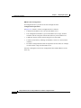
Large Campus Configuration
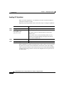
Figure 1-4 shows a configuration for a network of more than 1000 users. Because
it can aggregate up to 130 Gigabit connections, a Catalyst 6500 multilayer switch
is used as the backbone switch.
You can use the workgroup configurations shown in previous examples to create
workgroups with Gigabit uplinks to the Catalyst 6500 switch. For example, you
can use switch clusters that have a mix of Catalyst 2900 XL and
Catalyst 3500 XL switches.
The Catalyst 6500 switch provides the workgroups with Gigabit access to core
resources:
•
Cisco 7000 series router for access to the WAN and the Internet.
•
Server farm that includes a call-processing server running Cisco CallManager
software. Cisco CallManager controls call processing, routing, and IP phone
features and configuration.
•
Cisco Access gateway (such as Cisco Access Digital Trunk Gateway or Cisco
Access Analog Trunk Gateway) that connects the IP network to the PSTN or
to users in an IP telephony network.
Catalyst 2900 Series XL and Catalyst 3500 Series XL Software Configuration Guide
1-18
78-6511-05
Chapter 1
Overview
Network Configuration Examples
Figure 1-4
Large Campus Configuration
IP telephony
network or
PSTN
WAN
Cisco
CallManager
Cisco 7200 Cisco access
or 7500 router gateway
Servers
Catalyst
6500 switch
Catalyst
2900 XL and 3500 XL
GigaStack cluster
1 Gbps
(2 Gbps
full duplex)
Catalyst
3524-PWR XL
GigaStack cluster
IP
IP
IP
Cisco IP Phones
IP
IP
Workstations running
Cisco SoftPhone software
IP
Cisco IP Phones
54571
AC
power
source
IP
Catalyst 2900 Series XL and Catalyst 3500 Series XL Software Configuration Guide
78-6511-05
1-19
Chapter 1
Overview
Network Configuration Examples
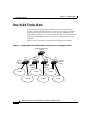
Hotel Network Configuration
Figure 1-5 shows the Catalyst 2900 LRE XL switches in a hotel network
environment with approximately 200 rooms. This network includes a private
branch exchange (PBX) switchboard, a router, and high-speed servers.
Connected to the telephone line in each hotel room is a Cisco 575 LRE CPE,
which provides both telephone and Ethernet connections. A room telephone
connects to the CPE phone port. The hotel customer would connect a laptop or the
television set-top box to the CPE Ethernet port. The laptop and telephone,
connected to the CPE, share the same telephone line.
Note
All telephones not directly connected to the hotel room CPE require
microfilters with a 300-Ohm termination. Microfilters improve voice call
quality when voice and data equipment are using the same telephone line.
They also prevent nonfiltered telephone rings and nonfiltered telephone
transitions (such as on-hook to off-hook) from interrupting the Ethernet
connection.
Through a patch panel, the telephone line from each room connects to a
nonhomologated POTS splitter, such as the Cisco LRE 48 POTS Splitter
(PS-1M-LRE-48). The splitter routes data (high-frequency) and voice
(low-frequency) traffic from the telephone line to the switch and PBX. The PBX
routes voice traffic to the PSTN. If a PBX is not available, a homologated POTS
splitter is required to connect to the PSTN. If a connection to a phone network is
not required at all, a splitter is not needed, and the switch can connect directly to
the patch panel.
Data to and from the laptop and IP multicast traffic for the television are
transferred through the LRE link, which is established between the CPE wall port
and the LRE port on a Catalyst 2900 LRE XL switch. The upstream and
downstream rates on the LRE link are controlled by a profile configured on each
LRE port. If the Catalyst 2900 LRE XL switches were connected to the PSTN
through a homologated POTS splitter, all LRE ports would use an
ANSI-compliant LRE profile named PUBLIC-ANSI.
Catalyst 2900 Series XL and Catalyst 3500 Series XL Software Configuration Guide
1-20
78-6511-05
Chapter 1
Overview
Network Configuration Examples
The Catalyst 2900 LRE XL switches are cascaded through the 10/100 switch
ports. Each switch also has a 10/100 connection to an aggregation switch, such as
a Catalyst 3524 XL switch. The aggregation switch can connect to
•
Accounting, billing, and provisioning servers.
•
A router that provides Internet access to the premises.
You can manage the switches through CMS as one or more switch clusters.
You can also manage and monitor the individual CPEs through the
Catalyst 2900 LRE XL switches to which they are connected. The LRE ports
support the same software features as the 10/100 ports. For example, you can
configure port-based VLANs on the LRE ports to provide individual port security
and protected ports to further prevent unwanted broadcasts within the VLANs.
Catalyst 2900 Series XL and Catalyst 3500 Series XL Software Configuration Guide
78-6511-05
1-21
Chapter 1
Overview
Network Configuration Examples
Figure 1-5
Hotel Network Configuration
Set-top box
PC
Telephones
Telephones
TV
Rooms
and
users
Required
microfilter
Cisco
LRE
CPE
Cisco
LRE
CPE
Required
microfilter
Floor 2
Set-top box
PC
Telephones
Telephones
TV
Rooms
and
users
Cisco
LRE
CPE
Required
microfilter
Required
microfilter
Cisco
LRE
CPE
Floor 1
Patch panel
Cisco
LRE 48
POTS
splitters
Catalyst 2900 LRE XL switches
Servers
PBX
Catalyst 2900 XL
or Catalyst 3500 XL switch
Cisco 2600 router
54573
PSTN
Catalyst 2900 Series XL and Catalyst 3500 Series XL Software Configuration Guide
1-22
78-6511-05
Chapter 1
Overview
Network Configuration Examples
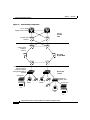
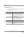
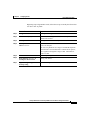
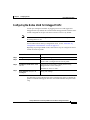
Multidwelling Configuration
A growing segment of residential and commercial customers are requiring
high-speed access to Ethernet metropolitan-area networks (MANs). Figure 1-6
shows a configuration for a Gigabit Ethernet MAN ring using Catalyst 6500
switches as aggregation switches in the mini-point-of-presence (POP) location.
These switches are connected through 1000BASE-X GBIC ports.
The resident switches can be Catalyst 2900 XL and Catalyst 3500 XL switches,
providing customers with either Fast Ethernet or Gigabit Ethernet connections to
the MAN. Catalyst 2900 LRE XL switches can also be used as residential
switches for customers requiring connectivity through existing telephone lines.
The Catalyst 2900 LRE XL switches can then connect to another residential
switch through a 10/100 connection.
All ports on the residential switches are configured as 802.1Q trunks with the
protected port and STP root guard options enabled. The protected port option
provides security and isolation between ports on the switch, ensuring that
subscribers cannot view packets destined for other subscribers. STP root guard
prevents unauthorized devices from becoming the STP root switch. All ports have
CGMP enabled for multicast traffic management. Higher VLAN and VLAN ID
(4096) support is ideal for more security flexibility.
Catalyst 2900 Series XL and Catalyst 3500 Series XL Software Configuration Guide
78-6511-05
1-23
Chapter 1
Overview
Network Configuration Examples
Figure 1-6
Multi-Dwelling Configuration
Cisco 12000
Gigabit switch routers
Service
Provider
POP
Catalyst 6500
switches
Catalyst 6500
multilayer
switches
Si
Si
Si
Si
Mini-POP
Gigabit MAN
Si
Si
Si
Si
Catalyst 2900 XL and
Catalyst 3500 XL
switches, including
Catalyst 2900 LRE XL
switches
Residential
location
Set-top box
Residential
gateway (hub)
Set-top box
54572
TV
PC
TV
Catalyst 2900 Series XL and Catalyst 3500 Series XL Software Configuration Guide
1-24
78-6511-05
C H A P T E R
2
Getting Started with CMS
This chapter describes the following features and interface components of the
Cluster Management Suite (CMS) software:
•
Visual Switch Manager (VSM) and Cluster Manager
•
Cluster Builder and Cluster View
•
CMS window components
This chapter also includes the following topics:
•
Accessing CMS
•
Saving changes on CMS
•
Using different versions of CMS
For system requirements and for browser and Java plug-in configurations, refer to
the release notes. For field-level descriptions of the CMS windows and for
procedures for using CMS, refer to the online help.
Note
This chapter describes the CMS interface used on the Catalyst 2900 XL and
Catalyst 3500 XL switches. Refer to the appropriate switch documentation for
descriptions of the web-based management software used on other Catalyst
desktop switches, such as the Catalyst 2950, Catalyst 1900, and Catalyst 2820
switches.
Catalyst 2900 Series XL and Catalyst 3500 Series XL Software Configuration Guide
78-6511-05
2-1
Chapter 2
Getting Started with CMS
Features
Features
CMS consists of the following integrated set of Java-based applications for
managing switch clusters and individual switches from a standard Web browser
such as Netscape Communicator or Microsoft Internet Explorer:
•
Cluster Manager and Visual Switch Manager (VSM)—Cluster Manager is the
application for configuring and monitoring the switches in a specific cluster.
When launched, it displays a front-panel view of all switches in the cluster.
VSM is the application for configuring and monitoring a standalone switch
or a specific switch in a cluster. It is also the application used to enable a
cluster command switch. When launched, it displays a front-panel view of a
specific switch.
Note
You can display VSM for a specific switch from Cluster Builder or
Cluster View by selecting Device > Launch Switch Manager. You
cannot display VSM from Cluster Manager. For more information
about accessing CMS, see the “Accessing CMS” section on page 2-35.
•
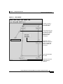
Cluster Builder and Cluster View—Cluster Builder is the application from
which you can create and modify a specific switch cluster. When launched, it
displays a topology (network map) of the cluster command switch, cluster
members, cluster candidates, edge devices, and the link speeds between all
cluster members.
Cluster View is the application from which you can display connected switch
clusters and neighboring edge devices in your network.
You can toggle between Cluster Builder and Cluster View by selecting
View > Toggle Views. For more information about accessing CMS, see the
“Accessing CMS” section on page 2-35.
The CMS windows use a consistent set of components (such as tabs, buttons,
drop-down lists, and so on), regardless of the CMS application you use. Each
CMS window also includes comprehensive online help, which provides
procedures for performing tasks from the window and high-level concepts.
Catalyst 2900 Series XL and Catalyst 3500 Series XL Software Configuration Guide
2-2
78-6511-05
Chapter 2
Getting Started with CMS
Cluster Manager and VSM
Cluster Manager and VSM
Cluster Manager is the CMS application for configuring the port-, switch-, and
cluster-level settings of the switches in a cluster. VSM is the application for
configuring switch- and port-level settings for a single switch.
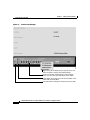
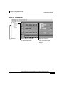
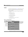
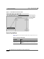
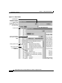
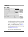
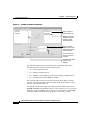
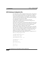
To assist in your configuration and monitoring tasks, both applications provide the
following features:
•
A display of switch images (Figure 2-1 and Figure 2-2) for visual monitoring
of the switches and switch ports. For information about using the switch
images, see the “Switch Images” section on page 2-7.
•
A menu bar that, except for a few options, provides the same options for
managing a single switch and clustered switches. This menu bar is described
in the “Menu Bars” section on page 2-14.
•
A toolbar that provides buttons for displaying commonly used, switch- and
cluster-level configuration windows and for displaying the legends and online
help. This toolbar is described in the “Toolbar” section on page 2-17.
•
A port-level pop-up menu for displaying windows specific for configuring
and monitoring switch ports. This pop-up menu is described in the “Port
Pop-Up Menu” section on page 2-18.
•
A device-level pop-up menu for displaying the configuration and monitoring
windows also available from the menu bar. This pop-up menu is described in
the “Device Pop-Up Menu” section on page 2-19.
The toolbar and pop-up menus provide quick ways to access the configuration and
monitoring options available from the menu bar.
Catalyst 2900 Series XL and Catalyst 3500 Series XL Software Configuration Guide
78-6511-05
2-3
Chapter 2
Getting Started with CMS
Cluster Manager and VSM
Figure 2-1
Visual Switch Manager
10.1.126.45
54513
10.1.126.45
Right-click a port to display the port pop-up menu, and
select an option to change port-related settings.
Press Ctrl, and then left-click ports to select multiple
ports. The color of the port reflects port or link status.
LEDs display the current port mode and the status of the
switch and connected RPS.
Left-click Mode to change the meaning of the port LEDs.
Catalyst 2900 Series XL and Catalyst 3500 Series XL Software Configuration Guide
2-4
78-6511-05
Chapter 2
Getting Started with CMS
Cluster Manager and VSM
Figure 2-2
Cluster Manager
54504
10.1.126.45
Cluster tree
Select a switch from the cluster
tree. The color of the switch
icon reflects switch status.
Right-click a switch to
display the device pop-up
menu, and select an option
to change system-related
settings.
Catalyst 2900 Series XL and Catalyst 3500 Series XL Software Configuration Guide
78-6511-05
2-5
Chapter 2
Getting Started with CMS
Cluster Manager and VSM
Cluster Tree
The cluster tree appears in the Cluster Manager left frame (Figure 2-2). It displays
a list of the switches in a specific cluster. The sequence of the cluster tree icons
mirrors the sequence of the switch front-panel images. Select a cluster-tree icon
to select the corresponding switch image. After you select a switch, you can
configure switch-wide settings from either the Cluster Manager menu bar options
or the device pop-up menu.
The cluster tree uses a subset of the same icons used in the topology displayed in
Cluster View and Cluster Builder. Figure 2-3 shows the device icons as they
appear in the cluster tree.
Figure 2-3
Cluster Tree Icons
The cluster tree displays the cluster name and the names and the status of cluster
members (Table 2-1). For example, a yellow switch icon in the cluster tree means
that particular switch is overheating or the fan is broken. Complete descriptions
of the icons and icon colors are available by selecting Help > Legend.
Table 2-1
Cluster Tree Icon Colors
Color
Switch Status
Green
Switch is operating normally.
Yellow
A system fault exists, such as the internal fan is not operating.
Red
Switch is not powered up, has lost power, or the command
switch is unable to communicate with the member switch.
Catalyst 2900 Series XL and Catalyst 3500 Series XL Software Configuration Guide
2-6
78-6511-05
Chapter 2
Getting Started with CMS
Cluster Manager and VSM
Switch Images
Use the front-panel images for visual switch management from a remote station.
The LEDs on these images are updated at user-configurable polling intervals,
making them as useful as the LEDs on the actual switches themselves. To change
the polling intervals, select System > User Settings from VSM or Cluster > User
Settings from Cluster Manager.
The following sections provide complete descriptions of the Catalyst 2900 XL
and Catalyst 3500 XL LED images:
•
System LED
•
RPS LED
•
Port LEDs
Summarized descriptions of the LED images are available from the VSM and
Cluster Manager menu bar by choosing Help > Legend.
System LED
The system LED shows whether the switch is receiving power and functioning
properly. Table 2-2 lists the LED colors and their meanings.
Table 2-2
System LED
Color
System Status
Black (off)
System is not powered up.
Green
System is operating normally.
Amber
System is receiving power but is not functioning properly.
Catalyst 2900 Series XL and Catalyst 3500 Series XL Software Configuration Guide
78-6511-05
2-7
Chapter 2
Getting Started with CMS
Cluster Manager and VSM
Redundant Power System LED
The Redundant Power System (RPS) LED shows the RPS status. Table 2-3 and
Table 2-4 list the LED colors and their meanings.
Note
Table 2-3
The Catalyst 2912 LRE XL, Catalyst 2924 LRE XL, and
Catalyst 3524-PWR XL switches use the Cisco RPS 300
(model PWR300-AC-RPS-N1). All other Catalyst 2900 XL and
Catalyst 3500 XL switches use the Cisco RPS 600
(model PWR600-AC-RPS). Refer to the appropriate switch documentation for
RPS descriptions specific for the switch.
Cisco RPS 600 LED on the Catalyst 2900 XL and Catalyst 3500 XL Switches Except the
Catalyst 2912 LRE, 2924-LRE, and 3524-PWR XL Switches
Color
RPS Status
Black (off)
RPS is off or is not installed.
Green
RPS is operational.
Blinking green
RPS and the switch AC power supply are both powered up. If the switch power
supply fails, the switch powers down and after 15 seconds restarts, using power
from the RPS. The switch goes through its normal boot sequence when it restarts.
Note
Amber
This is not a recommended configuration.
RPS is connected but not functioning properly. One of the power supplies in the
RPS could be powered down, or a fan on the RPS could have failed.
Catalyst 2900 Series XL and Catalyst 3500 Series XL Software Configuration Guide
2-8
78-6511-05
Chapter 2
Getting Started with CMS
Cluster Manager and VSM
Table 2-4
Cisco RPS 300 LED on the Catalyst 2912 LRE, 2924-LRE, and 3524-PWR XL Switches
Color
RPS Status
Black (off)
RPS is off or is not installed.
Green
RPS is connected and operational.
Blinking green
RPS is backing up another switch in the stack.
Amber
RPS is connected but not functioning. The following conditions could exist:
Blinking amber
•
The RPS could be in standby mode. To put the RPS in Active mode, press the
Standby/Active button on the RPS, and the LED should turn green. If it does
not, one of these other two conditions could exist.
•
One of the RPS power supplies could be down. Contact Cisco Systems.
•
The RPS fan could have failed. Contact Cisco Systems.
Internal power supply of the switch is down, and redundancy is lost. The switch is
operating on the RPS.
Port Modes and LEDs
The port modes (Table 2-5) determine the type of information displayed through
the port LEDs. When you change port modes, the meaning of the port LED colors
also changes.
Note
The bandwidth utilization mode (UTIL LED) is not displayed on the VSM or
Cluster Manager switch images. Select Monitoring > Bandwidth Graph to
display the total bandwidth in use by the switch. Refer to the switch hardware
installation guide for information about using the UTIL LED.
To select or change a mode, click Mode until the desired mode LED is green.
Catalyst 2900 Series XL and Catalyst 3500 Series XL Software Configuration Guide
78-6511-05
2-9
Chapter 2
Getting Started with CMS
Cluster Manager and VSM
Table 2-5
Port Modes
Mode LED
Description
STAT
Ethernet link status of the 10/100, 100BASE-FX, or 1000BASE-X
switch ports, or the Ethernet link status on the remote CPE.
Default mode on all Catalyst 2900 XL and Catalyst 3500 XL switches
except the Catalyst 2900 LRE XL switches.
LRE
(Catalyst 2900 LRE XL only)
Long-Reach Ethernet (LRE) link status of the LRE ports on the
Catalyst 2900 LRE XL switches.
Default mode on these switches only.
Note
FDUP or DUPLX
Duplex setting on the ports.
•
Default setting is auto on all Catalyst 2900 XL and
Catalyst 3500 XL switches and on the 10/100 ports on the
Catalyst 2900 LRE XL switches.
•
Default setting is half-duplex on the LRE ports on the
Catalyst 2900 LRE XL switches.
Note
SPEED or SPD
When the LRE mode is active, the 10/100 switch ports on
the Catalyst 2900 LRE XL continue to show Ethernet link
status.
On the Catalyst 2900 LRE XL switches, this LED shows
the duplex mode used on the Ethernet link between the
remote customer premises equipment (CPE) and Ethernet
device.
Speed setting on the ports. Default setting is auto.
Note
On the Catalyst 2900 LRE XL switches, this LED shows
the link speed between the remote CPE and Ethernet
device.
LINE PWR
Inline power setting on the Catalyst 3524-PWR XL 10/100 ports.
(Catalyst 3524-PWR XL only) Default setting is auto.
Catalyst 2900 Series XL and Catalyst 3500 Series XL Software Configuration Guide
2-10
78-6511-05
Chapter 2
Getting Started with CMS
Cluster Manager and VSM
Table 2-6, Table 2-7, and Table 2-8 explain how to interpret the port LED colors
after you change the port mode.
On the modular switches, the 1 or 2 LED is green when a module is installed.
Refer to the module documentation for complete information.
Table 2-6
Port LEDs on the Catalyst 2912, 2924C, 2924, 2912MF, and 2924M XL Switches
Port Mode
Port LED Color
Description
STAT
Cyan (off)
No link.
Green
Link present.
Blinking green Activity on the port. Port is transmitting or receiving data.
Amber
Link fault. Error frames can affect connectivity, and errors such as
excessive collisions, CRC errors, and alignment and jabber errors are
monitored for a link-fault indication.
Port is not forwarding. Port was disabled by management, or by an
address violation, or was blocked by Spanning Tree Protocol (STP).
Note
FDUP
SPD
After a port is reconfigured, the port LED can remain amber
for up to 30 seconds as STP checks the switch for possible
loops.
Brown
No link and port is administratively shut down.
Cyan (off)
Port is operating in half-duplex mode.
Green
Port is operating in full-duplex mode.
Cyan (off)
Port is operating at 10 Mbps.
Green
Port is operating at 100 Mbps.
Catalyst 2900 Series XL and Catalyst 3500 Series XL Software Configuration Guide
78-6511-05
2-11
Chapter 2
Getting Started with CMS
Cluster Manager and VSM
Table 2-7
LRE Port LEDs on the Catalyst 2900 LRE XL Switches1
Port Mode
Port LED
Color
Description
LRE2
Cyan (off)
No LRE link present on the LRE port.
Green
LRE link present on the LRE port. Port LED turns green in approximately
10 seconds after the LRE port detects a connection to a Cisco 575 LRE CPE.
Amber
LRE port on the switch and WALL port on the Cisco 575 LRE CPE unable
to establish the rate defined by the assigned profile. Refer to the
“Troubleshooting LRE Port Configuration” section on page 9-4.
Cyan (off)
No Ethernet link present on the 10/100 switch port or on the remote CPE
Ethernet port.
Green
Ethernet link present on the 10/100 switch port or on the remote CPE
Ethernet port.
Blinking
green
Activity on the 10/100 switch port or on the remote CPE Ethernet port. Port
is transmitting or receiving data.
Amber
Link fault. Error frames can affect connectivity, and errors such as
excessive collisions, CRC errors, and alignment and jabber errors are
monitored for a link-fault indication.
STAT
10/100 switch port or remote CPE Ethernet port is not forwarding. Port was
disabled by management, by an address violation, or was blocked by STP.
Note
DUPLX
SPEED
After a port is reconfigured, the port LED can remain amber for
up to 30 seconds as STP checks the switch for possible loops.
Brown
No link and port is administratively shut down.
Cyan (off)
10/100 switch port or remote CPE Ethernet port is operating in half-duplex
mode.
Green
10/100 switch port or remote CPE Ethernet port is operating in full-duplex
mode.
Cyan (off)
10/100 switch port or remote CPE Ethernet port is operating at 10 Mbps.
Green
10/100 switch port or remote CPE Ethernet port is operating at 100 Mbps.
1. In STAT mode, the LRE ports reflect the Ethernet link between the remote CPE and Ethernet device, such as a PC. The
Ethernet link default settings on the LRE ports are different than those on the 10/100 ports. See Table 2-5.
2. In LRE mode, the 10/100 port LEDs continue to reflect Ethernet link status.
Catalyst 2900 Series XL and Catalyst 3500 Series XL Software Configuration Guide
2-12
78-6511-05
Chapter 2
Getting Started with CMS
Cluster Manager and VSM
Table 2-8
Port LEDs on the Catalyst 3500 XL Switches
Port Mode
Port LED Color Description
STATUS
Cyan (off)
No link.
Green
Link present.
Blinking
green
Activity on the port. Port is transmitting or receiving data.
Amber
Link fault. Error frames can affect connectivity, and errors
such as excessive collisions, CRC errors, and alignment
and jabber errors are monitored for a link-fault indication.
Port is not forwarding. Port was disabled by management,
by an address violation, or was blocked by STP.
Note
DUPLEX
SPEED
After a port is reconfigured, the port LED can
remain amber for up to 30 seconds as STP checks
the switch for possible loops.
Brown
No link and port is administratively shut down.
Cyan (off)
Port is operating in half-duplex mode.
Green
Port is operating in full-duplex mode.
10/100 Ports
Cyan (off)
Port is operating at 10 Mbps.
Green
Port is operating at 100 Mbps.
1000BASE-X Ports
Cyan (off)
Port is not operating.
Green
Port is operating at 1000 Mbps.
LINE PWR
Cyan (off)
(Catalyst 3524-PWR XL Green
only)
Inline power is off.
Inline power is on.
If the Cisco IP Phone is receiving power from an AC power
source, the port LED is off even if the IP phone is
connected to the switch port. The LED turns green only
when the switch port is providing power.
Catalyst 2900 Series XL and Catalyst 3500 Series XL Software Configuration Guide
78-6511-05
2-13
Chapter 2
Getting Started with CMS
Cluster Manager and VSM
Menu Bars
The VSM menu bar provides the options for configuring and monitoring a single
switch. The Cluster Manager menu bar provides the options for configuring and
monitoring a switch or a switch cluster.
The menu bars (Figure 2-1 and Figure 2-2) are similar, but with the following
exceptions:
•
Some configuration options, such as some system and VLAN options, are
arranged slightly differently in VSM and Cluster Manager.
•
The option for enabling a command switch is available only from VSM.
•
The option for designating a standby group of command switches is available
only from Cluster Manager.
•
The option for rearranging the switch images is available only from Cluster
Manager.
Table 2-9 describes the VSM and Cluster Manager menu bar options and their
function and shows where the two menu bars differ.
Catalyst 2900 Series XL and Catalyst 3500 Series XL Software Configuration Guide
2-14
78-6511-05
Chapter 2
Getting Started with CMS
Cluster Manager and VSM
Table 2-9
VSM and Cluster Manager Menu Bars
Menu Bar Options
Task
Cluster (VSM-specific)
Cluster Command
Configuration
Enable a switch to act as the cluster command switch.
Cluster Management
Display Cluster Manager or Cluster Builder.
Cluster (Cluster Manager-specific)
Management VLAN
Change the management VLAN for a cluster.
System Time Management
Configure the system time or configure the Network Time Protocol
(NTP).
VMPS Configuration
Configure the VLAN Membership Policy Server.
Standby Command
Configuration
Create an Hot Standby Router Protocol (HSRP) standby group to
provide command-switch redundancy.
Device Position
Rearrange the order in which switches appear in Cluster Manager.
User Settings
Set the polling interval for Cluster Manager, Cluster Builder, and the
performance graphs. Set the application to display by default.
Cluster Builder
Display Cluster Builder.
System
Inventory
Display the device type, software version, IP address, and other
information about a switch or a cluster of switches.
IP Management
Configure IP information for a switch.
Software Upgrade
Upgrade the software for the cluster or a switch.
System Time Management
(VSM-specific)
Configure the system time or the NTP.
SNMP Management
Enter Simple Network Management Protocol (SNMP) community
strings, and configure end stations as trap managers.
Console Baud Rate
Change the baud rate for a switch.
ARP Table
Display the device Address Resolution Protocol (ARP) table.
User Settings (VSM-specific) Change the polling intervals for clustering and graphing, and enable
the display of the splash page when VSM starts.
Save Configuration
Save the configuration.
System Reload
Reboot the software on a switch.
Catalyst 2900 Series XL and Catalyst 3500 Series XL Software Configuration Guide
78-6511-05
2-15
Chapter 2
Getting Started with CMS
Cluster Manager and VSM
Table 2-9
VSM and Cluster Manager Menu Bars (continued)
Menu Bar Options
Task
Device
Cisco Group Management
Protocol (CGMP)
Enable and disable the CGMP and the CGMP Fast Leave feature on a
switch.
Spanning-Tree Protocol (STP) Display and configure STP parameters for a switch.
LRE Profile
Display the LRE profile settings for the Catalyst 2900 LRE XL
switches, and configure the speed of the LRE link.
Port
Port Configuration
Display and configure port parameters on a switch.
Port Statistics
Display the Ethernet and LRE link statistics.
Port Search
Search for a port through its description.
Port Grouping (EtherChannel) Group ports into logical units for high-speed links between switches.
Switch Port Analyzer (SPAN) Enable SPAN port monitoring.
Flooding Control
Enable broadcast storm control and block unicast and multicast
flooding on a per-port basis.
VLAN
VLAN Membership
Display VLAN membership, assign ports to VLANs, and configure
Inter-Switch Link (ISL) and 802.1Q trunks.
Management VLAN
(VSM-specific)
Change the management VLAN on the switch.
VTP Management
Display and configure the VLAN Trunk Protocol (VTP) for
interswitch VLAN membership.
VMPS Configuration
(VSM-specific)
Configure the VLAN Membership Policy Server (VMPS).
Security
Address Management
Enter dynamic, secure, and static addresses into a switch address table.
You can also define the static addresses forwarding behavior.
Port Security
Enable port security on a port.
Help
Contents
List all of the available online help topics.
Legend
Display the legend that describes the icons, labels, and links.
About
Display the version number of VSM or Cluster Manager.
Catalyst 2900 Series XL and Catalyst 3500 Series XL Software Configuration Guide
2-16
78-6511-05
Chapter 2
Getting Started with CMS
Cluster Manager and VSM
Toolbar
The VSM and Cluster Manager toolbar (Figure 2-4) buttons display some switchand cluster-level configuration windows. Hover the cursor over a button to
display a pop-up description. From left to right on the toolbar, the following
windows can be displayed:
Figure 2-4
•
Cluster Builder (On VSM, this button is not applicable and is therefore
disabled.)
•
Software Upgrade window
•
SNMP Management window
•
VLAN Membership window
•
Spanning Tree Protocol window
•
Save Configuration window
•
User Settings window
•
Legend that describes the icons, labels, and links
•
Online help table of contents
Cluster Manager Toolbar
54511
10.1.126.45
Move the cursor over
the icon to display the
tool tip. For example,
the ? button displays
Help Contents.
Catalyst 2900 Series XL and Catalyst 3500 Series XL Software Configuration Guide
78-6511-05
2-17
Chapter 2
Getting Started with CMS
Cluster Manager and VSM
Port Pop-Up Menu
You can display all port configuration windows from the Port menu on the menu
bar, or you can display a subset of the port configuration windows from the VSM
and Cluster Manager port pop-up menu. The port pop-up menu provides options
for displaying commonly used port configuration windows (Table 2-10). From the
port pop-up menu, you can configure a single port or configure multiple ports to
run with the same settings.
To display the port pop-up menu from VSM or Cluster Manager, you can either
•
Click a specific port image, and right-click.
•
Press the Ctrl key, click the port images on a single switch or on different
switches, and right-click.
Table 2-10 VSM and Cluster Manager Port Pop-up Menu
Pop-up Menu Option
Task
Port Configuration
Display and configure port parameters on a switch.
VLAN Membership
Define the VLAN mode for a port or ports, and add ports to VLANs. Not
available for Catalyst 1900 or Catalyst 2820 switches.
Flooding Controls
Block the normal flooding of unicast and multicast packets, and enable the
switch to block packet storms. Not available for Catalyst 1900 or Catalyst 2820
switches.
Port Security
Enable port security on a port. Not available for Catalyst 1900 or Catalyst 2820
switches.
Link Graph
Right-click a port that is green to display the performance graph for the link.
You can plot the link utilization percentage and the total packets, bytes, and
errors recorded on the link. This feature is not available on Catalyst 1900 and
Catalyst 2820 switches. For more information about link graphs, refer to the
online help.
Note
This feature is only available when selecting an individual port.
Catalyst 2900 Series XL and Catalyst 3500 Series XL Software Configuration Guide
2-18
78-6511-05
Chapter 2
Getting Started with CMS
Cluster Manager and VSM
Device Pop-Up Menu
With the exception of the Cluster menu bar options, the VSM and Cluster
Manager device pop-up menu displays all of the configuration and monitoring
windows (Table 2-11) available from the VSM and Cluster Manager menu bar.
To display the device pop-up menu from VSM, click the switch image, and
right-click.
To display the device pop-up menu from Cluster Manager, you can either
•
Click a specific switch icon from the Cluster Tree, and right-click.
•
Press the Ctrl key, click the switch icons from the Cluster Tree, and
right-click.
Table 2-11 VSM and Cluster Manager Device Pop-up Menu
Pop-up Menu Options
Task
System
Inventory
Display the device type, software version, IP address, and other
information about a switch or cluster of switches.
IP Management
Configure IP information for a switch.
Software Upgrade
Upgrade the software for a cluster or a switch.
SNMP Management
Enter SNMP community strings, and configure end stations as trap
managers.
Console Baud Rate
Change the baud rate for one or more switches.
ARP Table
Manage the Address Resolution Protocol (ARP) table.
Save Configuration
Save the configuration on one or all of the cluster switches.
System Reload
Reboot the software on a switch or a cluster.
Device
Cisco Group Management
Protocol (CGMP)
Enable and disable CGMP and the CGMP Fast Leave feature on a
switch.
Spanning Tree Protocol (STP)
Change STP parameters to prevent network loops.
LRE Profile
Display the LRE profile parameters for the Catalyst 2912 LRE and
Catalyst 2924 LRE XL switches, and configure the speed of the
LRE link between an LRE port and a remote CPE.
Catalyst 2900 Series XL and Catalyst 3500 Series XL Software Configuration Guide
78-6511-05
2-19
Chapter 2
Getting Started with CMS
Cluster Manager and VSM
Table 2-11 VSM and Cluster Manager Device Pop-up Menu (continued)
Pop-up Menu Options
Task
Port
Port Configuration
Display and configure port parameters on a switch.
Port Statistics
Display the Ethernet and LRE link statistics.
Port Search
Search for a port through its description.
Port Grouping (EC)
Group ports into logical units for high-speed links between
switches.
Switch Port Analyzer (SPAN)
Enable SPAN port monitoring.
Flooding Control
Enable broadcast storm control, and block unicast and multicast
flooding on a per-port basis.
VLAN
VLAN Membership
Display VLAN membership, assign ports to VLANs, and
configure ISL and IEEE 802.1Q trunks.
VTP Management
Display and configure the VLAN Trunk Protocol (VTP) for
interswitch VLAN membership.
Security
Address Management
Enter dynamic, secure, and static addresses into a switch address
table, and define the forwarding behavior of static addresses.
Port Security
Enable port security on a port.
Monitoring
Bandwidth Graph
Display a graph that plots the total bandwidth in use by the switch.
This feature is not available on the Catalyst 1900 and
Catalyst 2820 switches. For more information about bandwidth
graphs, refer to the online help.
Catalyst 2900 Series XL and Catalyst 3500 Series XL Software Configuration Guide
2-20
78-6511-05
Chapter 2
Getting Started with CMS
Cluster View and Cluster Builder
Cluster View and Cluster Builder
Cluster View (Figure 2-5) and Cluster Builder (Figure 2-6) are the CMS
applications for displaying, creating, and modifying switch clusters.
To assist in your cluster configuration and monitoring tasks, both applications
provide the following features:
•
Cluster View displays a high-level topology where clusters are collapsed and
represented as double-switch icons with links to candidate switches, other
switch clusters, and edge devices.
Cluster Builder displays the topology of a specific switch cluster, where
switches and cluster- and command-capable devices connected to the
command switch display as cluster members or candidates.
The components used in a topology are described in the “Topology” section
on page 2-24.
•
A menu bar that provides the options for creating, modifying, monitoring, and
displaying switch clusters. This menu bar is further described in the “Menu
Bar” section on page 2-26.
•
A toolbar that provides buttons for displaying commonly used cluster
configuration windows and for displaying the legends and online help. This
toolbar is described in the “Toolbar” section on page 2-27.
•
A device-level pop-up menu in Cluster View. This pop-up menu is described
in the “Device Pop-Up Menu” section on page 2-28
•
Device- and link-level pop-up menus in Cluster Builder. These pop-up menus
are described in the “Candidate, Member, and Link Pop-Up Menus” section
on page 2-29.
The toolbar and pop-up menus provide quick ways to access the configuration and
monitoring options available from the menu bar.
Catalyst 2900 Series XL and Catalyst 3500 Series XL Software Configuration Guide
78-6511-05
2-21
Chapter 2
Getting Started with CMS
Cluster View and Cluster Builder
Figure 2-5
Cluster View
Cluster is collapsed to a
double-switch icon.
Connected cluster.
54505
mcluster
Status bar shows that
Cluster View is displayed.
Catalyst 2900 Series XL and Catalyst 3500 Series XL Software Configuration Guide
2-22
78-6511-05
Chapter 2
Getting Started with CMS
Cluster View and Cluster Builder
Figure 2-6
Cluster Builder
A switch icon with a
crown indicates the
command switch.
Lines indicate the type
of connection between
two devices, such as
lightning bolts are
Gigastack GBIC
connections.
Switch202
Right-click a line to
display the link pop-up
menu, and select an
option to display link
information.
54503
Device label identifies
the switch.
Status bar shows that
Cluster Builder is
displayed.
Catalyst 2900 Series XL and Catalyst 3500 Series XL Software Configuration Guide
78-6511-05
2-23
Chapter 2
Getting Started with CMS
Cluster View and Cluster Builder
Topology
The topology appears when you launch use Cluster View and Cluster Builder. It
displays connected clusters, command switches, cluster members, candidate
switches, and edge devices. From the topology, you can:
•
Double-click a cluster icon (double-switch icon) to display cluster members.
•
Select a command-switch icon to configure cluster-wide settings.
•
Select a switch icon to configure switch-wide settings.
The topology in Cluster View (Figure 2-5) and Cluster Builder (Figure 2-6) uses
the same icons used in the Cluster Manager cluster tree (Figure 2-2). It also uses
an icon unique to the topology. This icon is the unknown device icon. Figure 2-7
shows the device icons as they appear in the topology. Table 2-12 describes the
meanings of the icon colors.
Figure 2-7
Cluster View and Cluster Builder Device Icons
Table 2-12 Icon Colors
Icon Color
Color Meaning
Green
Device is up.
Red
Device is down.
Yellow
Fault indication.
Catalyst 2900 Series XL and Catalyst 3500 Series XL Software Configuration Guide
2-24
78-6511-05
Chapter 2
Getting Started with CMS
Cluster View and Cluster Builder
The topology includes device labels, which are the switch cluster names, cluster
member names, and MAC addresses (Figure 2-6). Table 2-13 describes the
meanings of the label colors. You can toggle device labels by selecting
View > Toggle Labels.
Table 2-13 Device Label Colors
Label Color
Color Meaning
Green
A cluster member, either a member switch or the command switch.
Cyan
A cluster candidate that is fully qualified to become a cluster member. Add these
candidates with Cluster Builder.
White
A standby command switch.
Yellow
An unknown edge device that cannot become a member.
The link icons in the topology describe the link type and status between two
devices. Figure 2-8 shows the device icons as they appear in the topology.
Table 2-14 describes the meanings of the link colors. When you point your cursor
at a link and right-click, you can display additional link information from the link
pop-up menu (Figure 2-6). Complete descriptions of the icons and icon colors are
available from Help > Legend.
Figure 2-8
Red
Blue
Red
and
and
yellow yellow
Gray
and
black
54566
Blue
Cluster View and Cluster Builder Link Icons
Table 2-14 Link Colors
Link Color
Color Meaning
Blue
Active link
Red
Blocked link
Catalyst 2900 Series XL and Catalyst 3500 Series XL Software Configuration Guide
78-6511-05
2-25
Chapter 2
Getting Started with CMS
Cluster View and Cluster Builder
Menu Bar
The Cluster View and Cluster Builder menu bar provides the options for
configuring and monitoring a switch cluster. Table 2-15 describes the Cluster
View and Cluster Builder menu bar options and their function.
Table 2-15 Cluster View and Cluster Builder Menu
Menu Bar Options
Task
Cluster
Add to cluster
Add candidates to cluster.
Remove from cluster
Remove members from cluster.
User Settings
Change the default settings for the number of hops to discover and the
polling interval for Cluster Builder and the link graphs.
Goto Cluster Manager
Start Cluster Manager.
Views
Toggle Views
Toggle between Cluster Builder and Cluster View.
Toggle Labels
Toggle between switch names and IP or MAC addresses and connected
port numbers.
Device
Launch Switch
Manager
Start Switch Manager for a selected switch.
Bandwidth Graph
Display a graph showing the current bandwidth in use by a selected switch.
Not supported on Catalyst 1900 and Catalyst 2820 switches.
Show/Hide Candidates
Expand or collapse image of all candidates connected to a cluster member.
Host Name
Configuration
Change the host name for a selected device.
Link
Link Graph
Display a graph showing the bandwidth being used for the selected link.
Link Report
Display the Link Report for two connected devices. If one device is an
unknown device, candidate switch, or Catalyst 1900 or Catalyst 2820
switch, only the cluster member side of the link is displayed.
Catalyst 2900 Series XL and Catalyst 3500 Series XL Software Configuration Guide
2-26
78-6511-05
Chapter 2
Getting Started with CMS
Cluster View and Cluster Builder
Table 2-15 Cluster View and Cluster Builder Menu (continued)
Menu Bar Options
Task
Options
Save Layout
Save the current arrangement in the topology.
Save Configuration
Save the current configuration of cluster members to Flash memory.
Help
Contents
List all of the available online help topics.
Legend
Display descriptions of the icons used in the topology.
About
Display the version number for Cluster Builder and Cluster View.
Toolbar
The Cluster Builder and Cluster View toolbar (Figure 2-9) buttons display some
cluster-level configuration windows. Hover the cursor over a button to display a
pop-up description. From left to right on the toolbar, the following windows can
be displayed:
•
Launch Cluster Manager.
•
Toggle between Cluster Builder and Cluster View—You can also use Cluster
Builder and Cluster View to manage your cluster. When you are using Cluster
Builder, click the double-switch icon on the toolbar (Figure 2-9) to toggle
back to Cluster Manager.
•
Toggle between switch names and IP or MAC addresses and connected port
numbers.
•
Save the arrangement of the cluster icons as you have arranged them.
•
Save the current configuration for all cluster members to Flash memory.
•
Set the user settings for Cluster Builder and Cluster View.
•
Display the legend that describes the icons, labels, and links that are used in
Cluster Builder and Cluster View.
•
List the online help topics for Cluster Builder and Cluster View.
Catalyst 2900 Series XL and Catalyst 3500 Series XL Software Configuration Guide
78-6511-05
2-27
Chapter 2
Getting Started with CMS
Cluster View and Cluster Builder
Figure 2-9
Cluster Builder and Cluster View Toolbar
Move the cursor over
the icon to display the
tool tip. For example,
the ? button displays
Help Contents.
54512
Switch202
Device Pop-Up Menu
Table 2-16 describes the menu options available when you right-click an icon in
Cluster View.
Table 2-16 Cluster View Device Menu
Menu Option
Action
Device Web Page
Displays the web management page for the device.
Disqualification Code
Describes why the switch is not a cluster member or
candidate.
Catalyst 2900 Series XL and Catalyst 3500 Series XL Software Configuration Guide
2-28
78-6511-05
Chapter 2
Getting Started with CMS
Cluster View and Cluster Builder
Candidate, Member, and Link Pop-Up Menus
Table 2-17 describes the menu options available when you right-click a
candidate-switch icon in Cluster Builder.
Table 2-17 Cluster Builder Candidate Pop-up Menu
Menu Option
Action
Device Web Page Displays the device-management page for the device.
Add to Cluster
Adds the selected candidate or candidates to the cluster.
Table 2-18 describes the menu options available when you right-click a
member-switch icon in Cluster Builder. For more information about configuring
cluster members, see Chapter 5, “Clustering Switches.”
Table 2-18 Cluster Builder Member Pop-up Menu
Menu Option
Action
Switch Manager
Display the VSM Home page for the selected device.
Bandwidth Graph
Display a graph that plots the total bandwidth used by
the switch. This feature is not available on
Catalyst 1900 or Catalyst 2820 switches.
Host Name Config
Change the name of the switch. For more information,
see the “Host Names” section on page 5-10.
Remove from Cluster
Remove the selected switch from the cluster.
Show or hide
Candidates
Toggle between displaying candidate switches and not
displaying them.
Clear State
Return switches that were down but are now up to the
green (up) state. Switches that are yellow are down or
were previously down. Applicable only to yellow
member switches.
Catalyst 2900 Series XL and Catalyst 3500 Series XL Software Configuration Guide
78-6511-05
2-29
Chapter 2
Getting Started with CMS
Cluster View and Cluster Builder
Table 2-19 describes the menu options available when you right-click a link in
Cluster Builder. For more information about displaying link information, refer to
the online help.
Table 2-19 Cluster Builder Link Pop-up Menu
Menu Option
Action
Link Graph
Display the performance graph for the link. One end of the
link must be connected to a port on a cluster member that is a
Catalyst 2900 XL or Catalyst 3500 XL switch. Links
between any mix of Catalyst 1900 and Catalyst 2820
switches cannot be graphed.
Link Report
Display information about the link between two members. If
one end of the link is a candidate, the report only displays
information about the member switch.
Catalyst 2900 Series XL and Catalyst 3500 Series XL Software Configuration Guide
2-30
78-6511-05
Chapter 2
Getting Started with CMS
CMS Window Components
CMS Window Components
CMS windows use consistent techniques to present configuration information.
Figure 2-10 shows the components of a typical CMS window.
Figure 2-10 CMS Window Components
Click a tab to display more
information.
Cluster members are listed
in the device list.
Click in a row to select it.
OK saves the changes you
have made and closes the
window.
Apply saves the changes
you have made and leaves
the window open.
Modify displays a pop-up
for the selected row.
32676
Cancel closes the window
without saving the changes.
Help displays help for the
current window and the
menu of Help topics.
Catalyst 2900 Series XL and Catalyst 3500 Series XL Software Configuration Guide
78-6511-05
2-31
Chapter 2
Getting Started with CMS
CMS Window Components
Host Name List
The Host Name drop-down list (also referred to as the Device list) shows a list of
cluster member names. To display or change the configuration of a specific switch
in a cluster, select the switch name. The current configuration settings of that
switch appear.
In some cases, switch-specific features (such as the LRE profiles on the
Catalyst 2900 LRE XL switches) are available only when the appropriate switch
is a member of the cluster. Otherwise, switch-specific features either are
grayed-out or are not shown in the CMS menu bar and pop-up menus.
In other cases, depending on the menu option selected, certain cluster members
names are not included in the Host Name list. For example, the VLAN
Membership window would not display Catalyst 1900 and Catalyst 2820
switches, even though they are part of the cluster.
Tabs
Some CMS windows have multiple tabs that present different kinds of
information. Tabs are arranged like folder headings across the top of the window.
Click the tab to display a new screen, and click Apply to save information on all
tabs but without closing the window.
Lists
Listed information can often be changed by selecting an item from a list. To
change the information, select one or more items, and click Modify. Changing
multiple items is limited to those items that apply to at least one of the selections.
For example, when you select multiple ports, a parameter such as flow control is
grayed out if the ports are not Gigabit Ethernet ports.
Tips
If you try to select a port or device in Cluster Manager while another CMS
window is open, the computer issues a ringing bell sound. Rearrange the
windows that are displayed to find the open window, and close it to proceed.
Catalyst 2900 Series XL and Catalyst 3500 Series XL Software Configuration Guide
2-32
78-6511-05
Chapter 2
Getting Started with CMS
CMS Window Components
Buttons
Table 2-20 describes the most common buttons that you use to change the
information in a CMS window:
Table 2-20 Common CMS Buttons
Button
Description
OK
Save any changes made in the window, and close the window.
Apply
Save any changes made in the window, and leave the window open.
Cancel
Do not save any changes made in the window, and close the window.
Modify
Display the pop-up for changing information on the selected item or items. You usually
select an item from a list or table and click Modify. When you close the pop-up, the
original window appears.
Online Help
CMS provides comprehensive online help to assist you in understanding and
performing configuration and monitoring tasks from the CMS windows
(Figure 2-11).
•
Feature help, available from all menu bars by selecting Help > Contents,
provides background information and concepts on the features.
•
Dialog-specific help, available from the Help button on the VSM and Cluster
Manager windows, provides descriptions of all window components (fields,
buttons, and so on) and procedures on performing tasks from the window.
•
Index of help topics.
You can send us feedback about the information provided in the online help. From
the menu bar, select Help > Contents, and click Feedback to display a simple
online form. After completing the form, click Submit to send your comments to
Cisco. We appreciate and value your comments.
Catalyst 2900 Series XL and Catalyst 3500 Series XL Software Configuration Guide
78-6511-05
2-33
Chapter 2
Getting Started with CMS
CMS Window Components
Figure 2-11 Help Contents
Click Back and
Forward to redisplay
previously displayed
pages. Click
Feedback to send us
your comments about
the online help.
Feature help.
Enter the first letters
of the topic, and click
Find.
Dialog-specific help.
4567
Click a topic under
the Contents or
Index tab.
Catalyst 2900 Series XL and Catalyst 3500 Series XL Software Configuration Guide
2-34
78-6511-05
Chapter 2
Getting Started with CMS
Accessing CMS
Accessing CMS
You must know the IP address and password of the specific switch or command
switch to access CMS. You can assign this information to the switch in the
following ways:
•
Using the setup program, as described in the release notes
•
Manually assigning an IP address and password, as described in the
“Changing IP Information” section on page 6-2 and “Changing the
Password” section on page 6-15.
Considerations for assigning this information to a command switch and
cluster members are described in the “IP Addresses” section on page 5-8 and
“Passwords” section on page 5-8.
Accessing CMS also requires meeting the software requirements, including
browser and Java plug-in configurations, described in the release notes.
Note
Copies of the CMS pages you display are saved in your browser memory cache
until you exit the browser session. A password is not required to redisplay
these pages, including the Cisco Systems Access page. You can access the CLI
by clicking Web Console - HTML access to the command line interface
from a cached copy of the Cisco Systems Access page. To prevent
unauthorized access to CMS and the CLI, exit your browser to end the browser
session.
Catalyst 2900 Series XL and Catalyst 3500 Series XL Software Configuration Guide
78-6511-05
2-35
Chapter 2
Getting Started with CMS
Accessing CMS
The following procedure assumes you have met the software requirements,
(including browser and Java plug-in configurations) and have assigned IP
information and a password to the switch or command switch, as described in the
release notes.
To access CMS, follow these steps:
Step 1
Enter the IP address in the browser Location field (Netscape Communicator) or
Address field (Microsoft Internet Explorer).
Step 2
Enter your userid and the password at the prompt.
The Cisco Systems Access page appears.
Step 3
Click Cluster Management Suite or Visual Switch Manager.
If you access CMS from a standalone or cluster member switch, VSM appears. If
you access CMS from a command switch, Cluster Builder launches by default.
You can select Cluster Manager to launch by default by selecting Cluster > User
Settings. You can toggle between Cluster Builder and Cluster View by selecting
View > Toggle Views.
You can display VSM for a specific cluster member from either Cluster Builder
or Cluster View by selecting Device > Launch Switch Manager. You cannot
display VSM from Cluster Manager.
For information about managing passwords in switch clusters, see the
“Passwords” section on page 5-8.
CMS requires that your switch uses Hypertext Transfer Protocol (HTTP) port 80,
which is the default HTTP port. If you change the HTTP port, you cannot access
CMS. For more information about the HTTP port, see the “HTTP Access to CMS”
section on page 4-5.
Catalyst 2900 Series XL and Catalyst 3500 Series XL Software Configuration Guide
2-36
78-6511-05
Chapter 2
Getting Started with CMS
Saving Configuration Changes
Saving Configuration Changes
The front-panel images and CMS windows always display the running
configuration of the switch. When you make a configuration change to a switch
or switch cluster, the change becomes part of the running configuration. The
change does not automatically become part of the config.txt file in Flash memory,
which is the startup configuration used each time the switch restarts. If you do not
save your changes to Flash memory, they are lost when the switch restarts.
To save all configuration changes to Flash memory, you must select System >
Save Configuration in the Cluster Manager menu bar or Options > Save
Configuration in the Cluster Builder or Cluster View menu bar.
Note
Catalyst 1900 and Catalyst 2820 switches automatically save configuration
changes to Flash memory as they occur.
Note
As you make cluster configuration changes (except for changes to the
topology and in the User Settings window), make sure you periodically save
the configuration. The configuration is saved on the command and member
switches.
Catalyst 2900 Series XL and Catalyst 3500 Series XL Software Configuration Guide
78-6511-05
2-37
Chapter 2
Getting Started with CMS
Using Different Versions of Web-Based Switch Management Software
Using Different Versions of Web-Based Switch
Management Software
Cluster command switches can manage a mixture of Catalyst desktop switches.
However, certain models of the Catalyst desktop switches support different
versions of web-based management software; thus, the interfaces can differ.
Keep in mind that when you select a switch image or switch icon and then select
Device > Launch Switch Manager from the menu bar, a new CMS session is
launched, and the web-based management software specific to that switch
appears.
•
The Catalyst 2900 XL, Catalyst 3500 XL, and Catalyst 2950 switches use the
same version of the CMS interface.
•
The Catalyst 1900 and Catalyst 2820 switches use an older interface version
of VSM, which is referred to as Switch Manager on these switches. Other
CMS features such as Cluster Manager, Cluster Builder, and Cluster View are
not available on these switches.
Refer to the appropriate switch documentation for descriptions of the web-based
management software used on other Catalyst desktop switches, such as the
Catalyst 2950, Catalyst 1900, and Catalyst 2820 switches.
Refer to the release notes for the list of Catalyst desktop switches that are
cluster-compatible and their software versions.
Where to Go Next
The rest of this guide provides descriptions of the software features and general
switch administration. Table 4-2 on page 4-9 lists the defaults for all key features,
gives the page number in this guide where the feature is described, and the name
of the CMS window from which you can configure the feature.
Refer to the online help for CMS procedures and window descriptions. Refer to
the release notes for hardware and software requirements, including required
browser versions, and for procedures for installing the required Java plug-in,
configuring your browser, and accessing CMS.
Catalyst 2900 Series XL and Catalyst 3500 Series XL Software Configuration Guide
2-38
78-6511-05
C H A P T E R
3
Getting Started with the CLI
This chapter provides information that you should know before using the Cisco
IOS command-line interface (CLI). If you have never used IOS software or if you
need a refresher, take a few minutes to read this chapter before reading the rest of
this guide.
•
Command usage basics
•
Command-line error messages
•
Accessing the CLI
•
Saving configuration changes
This switch software release is based on Cisco IOS Release 12.0(5). It has been
enhanced to support a set of features for the Catalyst 2900 XL and
Catalyst 3500 XL switches. This guide provides procedures for using only the
commands that have been created or changed for these switches. The
Catalyst 2900 Series XL and Catalyst 3500 Series XL Command Reference
provides complete descriptions of these commands.
For information about the standard Cisco IOS Release 12.0 commands, refer to
the Cisco IOS Release 12.0 documentation on Cisco.com.
Catalyst 2900 Series XL and Catalyst 3500 Series XL Software Configuration Guide
78-6511-05
3-1
Chapter 3
Getting Started with the CLI
Command Usage Basics
Command Usage Basics
This section provides the following topics:
•
Accessing command modes
•
Abbreviating commands
•
Using the No and Default forms of commands
•
Redisplaying a command
•
Getting help
Accessing Command Modes
The CLI is divided into different modes. The commands available to you at any
given time depend on which mode you are in. Entering a question mark (?) at the
system prompt provides a list of commands for each command mode.
The switch supports the following command modes:
•
User EXEC
•
Privileged EXEC
•
VLAN database
•
Global configuration
•
Interface configuration
•
Line configuration
When you start a session on the switch, you begin in user mode, often called user
EXEC mode, which has only a limited subset of the commands. To access all
commands and modes, you must first enter privileged EXEC mode. Normally, a
password is required to enter privileged EXEC mode. From privileged mode, you
can enter any EXEC command or enter global configuration mode. Most of the
EXEC commands are one-time commands, such as show commands, which show
the current configuration status, and clear commands, which clear counters or
interfaces.
You can use the virtual LAN (VLAN) database and the various configuration
modes to make changes to the running configuration. To access the various
configuration modes, you must start at global configuration mode. From global
configuration mode, you can enter interface and line configuration modes.
Catalyst 2900 Series XL and Catalyst 3500 Series XL Software Configuration Guide
3-2
78-6511-05
Chapter 3
Getting Started with the CLI
Command Usage Basics
Each command mode supports specific Cisco IOS commands. For example, the
interface command is used only from global configuration mode.
Table 3-1 describes how to access each mode, the prompt you see in that mode,
and how to exit the mode. The examples in the table use the host name switch.
Table 3-1
Command Modes Summary
Modes
Access Method
Prompt
Exit Method
About This Mode1
User EXEC
Begin a session
with your switch.
switch>
Enter logout or
quit.
Use this mode to
•
Change
terminal
settings.
•
Perform basic
tests.
•
Display
system
information.
Privileged
EXEC
Enter the enable
command while in
user EXEC mode.
switch#
Enter disable to
exit.
Use this mode to
verify commands
you have entered.
Use a password to
protect access to
this mode.
VLAN
database
Enter the vlan
database command
while in privileged
EXEC mode.
switch(vlan)#
To exit to
privileged EXEC
mode, enter exit.
Use this mode to
configure
VLAN-specific
parameters.
Catalyst 2900 Series XL and Catalyst 3500 Series XL Software Configuration Guide
78-6511-05
3-3
Chapter 3
Getting Started with the CLI
Command Usage Basics
Table 3-1
Command Modes Summary (continued)
Prompt
Exit Method
About This Mode1
Global
Enter the configure
configuration command while in
privileged EXEC
mode.
switch(config)#
To exit to
privileged EXEC
mode, enter exit or
end, or press
Ctrl-Z.
Use this mode to
configure
parameters that
apply to your
switch as a whole.
Interface
Enter the interface
configuration command (with a
specific interface)
while in global
configuration mode.
switch(config-if)#
To exit to global
configuration
mode, enter exit.
Use this mode to
configure
parameters for the
Ethernet
interfaces.
Line
Specify a line with
configuration the line vty or line
console command
while in global
configuration mode.
switch(config-line)#
Modes
Access Method
To exist to
privileged EXEC
mode, enter
Ctrl-Z or end.
To exit to global
configuration
mode, enter exit.
To exit to
privileged EXEC
mode, enter
Ctrl-Z or end.
Use this mode to
configure
parameters for the
terminal line.
1. For any of the modes, you can see a comprehensive list of the available commands by entering a question mark (?) at the
prompt.
Abbreviating Commands
You can abbreviate commands and keywords to the number of characters that
allow a unique abbreviation. For example, you can abbreviate the show command
to sh or the show configuration command to show conf.
Catalyst 2900 Series XL and Catalyst 3500 Series XL Software Configuration Guide
3-4
78-6511-05
Chapter 3
Getting Started with the CLI
Command Usage Basics
Using the No and Default Forms of Commands
Almost every configuration command has a no form. In general, use the no form
to
•
Disable a feature or function.
•
Reset a command to its default values.
•
Reverse the action of a command. For example, the no shutdown command
reverses the shutdown of an interface.
Use the command without the no form to reenable a disabled feature or to reverse
the action of a no command.
Configuration commands can also have a default form. The default form of a
command returns the command setting to its default.
Redisplaying a Command
To redisplay a command you previously entered, press the up-arrow key. You can
continue to press the up-arrow key for more commands.
Getting Help
Entering a question mark (?) at the system prompt displays a list of commands for
each command mode. You can also get a list of any command’s associated
keywords and arguments with the context-sensitive help feature.
The following are the commands to get help specific to a command mode, a
command, a keyword, or an argument:
•
help—Obtain a brief description of the help system in any command mode.
switch> help
•
abbreviated-command-entry?—Obtain a list of commands that begin with a
particular character string.
switch> dis?
switch> disable
disconnect
Catalyst 2900 Series XL and Catalyst 3500 Series XL Software Configuration Guide
78-6511-05
3-5
Chapter 3
Getting Started with the CLI
Command Usage Basics
•
Note
abbreviated-command-entry<Tab>—Complete a partial command name.
No space before tabbing.
switch# sh conf<tab>
switch# sh configuration
•
? — List all commands available for a particular command mode.
switch> ?
•
command ?—List of command keywords.
switch> show ?
•
command keyword ?— List of command keyword arguments.
switch> show udld ?
FastEthernet
FastEthernet IEEE 802.3
Null
Null interface
VLAN
Switch VLAN Virtual Interface
When using context-sensitive help, the space (or lack of a space) before the
question mark (?) is significant. To obtain a list of commands that begin with a
particular character sequence, enter those characters followed immediately by the
question mark (?). Do not include a space. This form of help is called word help,
because it completes a word for you.
To list keywords or arguments, enter a question mark (?) in place of a keyword or
argument. Include a space before the ?. This form of help is called command
syntax help, because it reminds you which keywords or arguments are applicable
based on the command, keywords, and arguments you already have entered.
Catalyst 2900 Series XL and Catalyst 3500 Series XL Software Configuration Guide
3-6
78-6511-05
Chapter 3
Getting Started with the CLI
Command-Line Error Messages
Command-Line Error Messages
Table 3-2 lists some error messages that you might encounter while using the CLI.
Table 3-2
Common CLI Error Messages
Error Message
Meaning
How to Get Help
% Ambiguous
command: "show con"
You did not enter enough
characters for your switch to
recognize the command.
Reenter the command followed by a space
and a question mark (?).
You did not enter all of the
keywords or values required by
this command.
Reenter the command followed by a space
and a question mark (?).
You entered the command
incorrectly. The caret (^) marks
the point of the error.
Enter a question mark (?) to display all of
the commands that are available in this
command mode.
% Incomplete
command.
% Invalid input
detected at ‘^’
marker.
The possible keywords that you can enter
with the command appear.
The possible keywords that you can enter
with the command appear.
The possible keywords that you can enter
with the command appear.
Catalyst 2900 Series XL and Catalyst 3500 Series XL Software Configuration Guide
78-6511-05
3-7
Chapter 3
Getting Started with the CLI
Accessing the CLI
Accessing the CLI
The following procedure assumes you have already assigned IP information and
password to the switch or command switch. You can assign this information to the
switch in the following ways:
•
Using the setup program, as described in the release notes
•
Manually assigning an IP address and password, as described in the
“Changing IP Information” section on page 6-2 and “Changing the
Password” section on page 6-15.
Considerations for assigning this information to a command switch and
cluster members are described in the “IP Addresses” section on page 5-8 and
“Passwords” section on page 5-8.
To access the CLI, follow these steps:
Step 1
Start up the emulation software (such as ProComm, HyperTerminal, tip, or
minicom) on the management station.
Step 2
If necessary, reconfigure the terminal-emulation software to match the switch
console port settings (default settings are 9600 baud, no parity, 8 data bits, and 1
stop bit).
Step 3
Establish a connection with the switch by either
•
Connecting the switch console port to a management station or dial-up
modem. For information about connecting to the console port, refer to the
switch hardware installation guide.
•
Using any Telnet TCP/IP package from a remote management station. The
switch must have network connectivity with the Telnet client, and the switch
must have an enable secret password configured. For information about
configuring the switch for Telnet access, see the “SNMP Network
Management Platforms” section on page 4-6.
The switch supports up to seven simultaneous Telnet sessions. Changes made
by one Telnet user are reflected in all other Telnet sessions.
After you connect through the console port or through a Telnet session, the
User EXEC prompt appears on the management station.
Catalyst 2900 Series XL and Catalyst 3500 Series XL Software Configuration Guide
3-8
78-6511-05
Chapter 3
Getting Started with the CLI
Accessing the CLI
Accessing the CLI from a Browser
The following procedure assumes you have met the software requirements,
(including browser and Java plug-in configurations) and have assigned IP
information and a Telnet password to the switch or command switch, as described
in the release notes.
To access the CLI from a web browser, follow these steps:
Step 1
Start one of the supported browsers.
Step 2
In the URL field, enter the IP address of the command switch.
Step 3
When the Cisco Systems Access page appears, click Telnet to start a Telnet
session.
You can also access the CLI by clicking Web Console - HTML access to the
command line interface from the Cisco Systems Access page. For information
about the Cisco Systems Access page, see the “Accessing CMS” section on
page 2-35 and the release notes.
Step 4
Enter the switch password.
The User EXEC prompt appears on the management station.
Note
Copies of the CMS pages you display are saved in your browser memory cache
until you exit the browser session. A password is not required to redisplay
these pages, including the Cisco Systems Access page. You can access the CLI
by clicking Web Console - HTML access to the command line interface
from a cached copy of the Cisco Systems Access page. To prevent
unauthorized access to CMS and the CLI, exit your browser to end the browser
session.
Catalyst 2900 Series XL and Catalyst 3500 Series XL Software Configuration Guide
78-6511-05
3-9
Chapter 3
Getting Started with the CLI
Saving Configuration Changes
Saving Configuration Changes
The show command always displays the running configuration of the switch.
When you make a configuration change to a switch or switch cluster, the change
becomes part of the running configuration. The change does not automatically
become part of the config.txt file in Flash memory, which is the startup
configuration used each time the switch restarts. If you do not save your changes
to Flash memory, they are lost when the switch restarts.
To save all configuration changes to Flash memory, you must enter the write
memory command in privileged EXEC mode.
Note
The write memory command does not apply to the Catalyst 1900 and
Catalyst 2820 switches, which automatically save configuration changes to
Flash memory as they occur.
Tips
As you make cluster configuration changes, make sure you periodically save
the configuration. The configuration is saved on the command and member
switches.
Where to Go Next
The rest of this guide provides descriptions of the software features and general
switch administration. Table 4-2 on page 4-9 lists the defaults for all key features
and gives the page numbers in this guide where the feature is described and CLI
procedures are provided.
Refer to the Catalyst 2900 Series XL and Catalyst 3500 Series XL Command
Reference for complete descriptions of the switch commands.
Refer to the Cisco IOS Release 12.0 documentation on Cisco.com for information
about the standard Cisco IOS Release 12.0 commands.
Catalyst 2900 Series XL and Catalyst 3500 Series XL Software Configuration Guide
3-10
78-6511-05
C H A P T E R
4
General Switch Administration
This chapter provides the following switch administration topics:
•
Basic IP connectivity to the switch
•
Switch software releases
•
Console port access
•
Hypertext Transfer Protocol (HTTP) access
•
Telnet access
•
Simple Network Management Protocol (SNMP) network management
platforms
•
Default settings of key software features
Refer to the release notes for information about starting up the switch:
•
Software and hardware requirements and compatibility
•
Browser and Java plug-in configurations
•
Setup program
Also refer to the release notes about switch upgrades.
For information about the standard Cisco IOS Release 12.0 commands, refer to
the Cisco IOS Release 12.0 documentation on Cisco.com.
Catalyst 2900 Series XL and Catalyst 3500 Series XL Software Configuration Guide
78-6511-05
4-1
Chapter 4
General Switch Administration
Basic IP Connectivity to the Switch
Basic IP Connectivity to the Switch
The switch uses IP address information to communicate with the local routers and
the Internet. You need it if you plan to use the CMS to configure and manage the
switch. The switch also requires a secret password. IP information is
•
Switch IP address
•
Subnet mask (IP netmask)
•
Default gateway (router)
Once IP information is assigned, you can run the switch on its default settings or
configure any settings to meet your network requirements.
The first time that you access the switch, it runs a setup program that prompts you
enter this information. For information about running the setup program and
assigning basic information to the switch, refer to the release notes.
Switch Software Releases
The switch software is regularly updated with new features and bug fixes, and you
might want to upgrade your Catalyst 2900 XL and Catalyst 3500 XL with the latest
software release. New software releases are posted on Cisco.com on the World
Wide Web and are available through authorized resellers. Cisco also supplies a
TFTP server that you can download from Cisco.com.
Before upgrading a switch, first find out the version of the software that the switch
is running. You can do this by using the Software Upgrade window, by selecting
Help > About, or by using the show version command.
Knowing the software version is also important for compatibility reasons,
especially for switch clusters. Refer to the release notes for the following
information:
•
Compatibility requirements
•
Upgrade guidelines and procedures and software reload information
Catalyst 2900 Series XL and Catalyst 3500 Series XL Software Configuration Guide
4-2
78-6511-05
Chapter 4
General Switch Administration
Console Port Access
Console Port Access
The switch console port provides switch access to a directly-attached terminal or
PC or to a remote terminal or PC through a serial connection and a modem. For
information about connecting to the switch console port, refer to the switch
hardware installation guide.
Be sure that the switch console port settings match the settings of the terminal or
PC. These are the default settings of the switch console port:
•
Baud rate default is 9600.
•
Data bits default is 8.
Note
If the data bits option is set to 8, set the parity option to None.
•
Stop bits default is 1.
•
Parity settings default is None.
Make sure that you save any changes you make to the switch console port settings
to Flash memory. For information about saving changes from CMS, see the
“Saving Configuration Changes” section on page 2-37. For information about
saving changes from the CLI, see the “Saving Configuration Changes” section on
page 3-10.
Catalyst 2900 Series XL and Catalyst 3500 Series XL Software Configuration Guide
78-6511-05
4-3
Chapter 4
General Switch Administration
Telnet Access to the CLI
Telnet Access to the CLI
The following procedure assumes you have assigned IP information and a Telnet
password to the switch or command switch, as described in the release notes.
Information about accessing the CLI through a Telnet session is provided in the
“Accessing the CLI” section on page 3-8.
To configure the switch for Telnet access, follow these steps:
Command
Step 1
Purpose
Attach a PC or workstation with emulation software to the
switch console port.
The default data characteristics of the switch console port
are 9600, 8, 1, no parity. When the command line appears,
go to Step 2.
Step 2
enable
Enter privileged EXEC mode.
Step 3
config terminal
Enter global configuration mode.
Step 4
line vty 0 15
Enter the interface configuration mode for the Telnet
interface.
There are 16 possible sessions on a command-capable
switch. The 0 and 15 mean that you are configuring all 16
possible Telnet sessions.
Step 5
password <password>
Enter a enable secret password.
Step 6
end
Return to privileged EXEC mode so that you can verify the
entry.
Step 7
show running-config
Display the running configuration.
The password is listed under the command line vty 0 15
Step 8
copy running-config
startup-config
(Optional) Save the running configuration to the startup
configuration.
Catalyst 2900 Series XL and Catalyst 3500 Series XL Software Configuration Guide
4-4
78-6511-05
Chapter 4
General Switch Administration
HTTP Access to CMS
HTTP Access to CMS
CMS uses Hypertext Transfer Protocol (HTTP), which is an in-band form of
communication with the switch through any one of its Ethernet ports and that
allows switch management from a standard web browser. CMS requires that your
switch uses HTTP port 80, which is the default HTTP port.
Note
If you change the HTTP port, you cannot use CMS.
Do not disable or otherwise misconfigure the port through which your
management station is communicating with the switch. You might want to write
down the port number to which you are connected. Changes to the switch IP
information should be done with care.
Refer to the following topics in the release notes for information about accessing
CMS:
•
System requirements
•
Running the setup program, which includes assigning a privilege-level 15
password for accessing CMS
•
Installing the required Java plug-in
•
Configuring your web browser
•
Displaying the Cisco Systems Access page
You can also refer to the “Accessing CMS” section on page 2-35.
For information about connecting to a switch port, refer to the switch hardware
installation guide.
Catalyst 2900 Series XL and Catalyst 3500 Series XL Software Configuration Guide
78-6511-05
4-5
Chapter 4
General Switch Administration
SNMP Network Management Platforms
SNMP Network Management Platforms
You can manage switches by using an Simple Network Management Protocol
(SNMP)-compatible management station running such platforms as HP
OpenView or SunNet Manager. CiscoWorks2000 and CiscoView 5.0 are
network-management applications you can use to configure, monitor, and
troubleshoot Catalyst 2900 XL and Catalyst 3500 XL switches.
The switch supports a comprehensive set of Management Information Base (MIB)
extensions and MIB II, the IEEE 802.1D bridge MIB, and four Remote
Monitoring (RMON) groups, which this IOS software release supports. You can
configure these groups by using an SNMP application or by using the CLI. The
four supported groups are alarms, events, history, and statistics.
This section describes how to access MIB objects to configure and manage your
switch. It provides the following information:
•
Using File Transfer Protocol (FTP) to access the MIB files
•
Using SNMP to access the MIB variables
In a cluster configuration, the command switch manages communication between
the SNMP management station and all switches in the cluster. For information
about managing cluster switches through SNMP, see the “Using SNMP to Manage
Switch Clusters” section on page 5-22.
When configuring your switch by using SNMP, note that certain combinations of
port features create configuration conflicts. For more information, see the
“Avoiding Configuration Conflicts” section on page 9-2.
Catalyst 2900 Series XL and Catalyst 3500 Series XL Software Configuration Guide
4-6
78-6511-05
Chapter 4
General Switch Administration
SNMP Network Management Platforms
Using FTP to Access the MIB Files
You can obtain each MIB file with the following procedure:
Step 1
Use FTP to access the server ftp.cisco.com.
Step 2
Log in with the username anonymous.
Step 3
Enter your e-mail username when prompted for the password.
Step 4
At the ftp> prompt, change directories to /pub/mibs/supportlists.
Step 5
Change directories to one of the following:
Step 6
•
wsc2900xl for a list of Catalyst 2900 XL MIBs
•
wsc3500xl for a list of Catalyst 3500 XL MIBs
Use the get MIB_filename command to obtain a copy of the MIB file.
You can also access this server from your browser by entering the following URL
in the Location field of your Netscape browser (the Address field in Internet
Explorer):
ftp://ftp.cisco.com
Use the mouse to navigate to the folders listed above.
Using SNMP to Access MIB Variables
The switch MIB variables are accessible through SNMP, an application-layer
protocol facilitating the exchange of management information between network
devices. The SNMP system consists of three parts:
•
The SNMP manager, which resides on the network management system
(NMS)
•
The SNMP agent, which resides on the switch
•
The MIBs that reside on the switch but that can be compiled with your
network management software
Catalyst 2900 Series XL and Catalyst 3500 Series XL Software Configuration Guide
78-6511-05
4-7
Chapter 4
General Switch Administration
SNMP Network Management Platforms
An example of an NMS is the CiscoWorks network management software.
CiscoWorks2000 software uses the switch MIB variables to set device variables
and to poll devices on the network for specific information. The results of a poll
can be displayed as a graph and analyzed to troubleshoot internetworking
problems, increase network performance, verify the configuration of devices,
monitor traffic loads, and more.
As shown in Figure 4-1, the SNMP agent gathers data from the MIB, which is the
repository for information about device parameters and network data. The agent
can send traps, or notification of certain events, to the SNMP manager, which
receives and processes the traps. Traps are messages alerting the SNMP manager
to a condition on the network such as improper user authentication, restarts, link
status (up or down), and so forth. In addition, the SNMP agent responds to
MIB-related queries sent by the SNMP manager in get-request, get-next-request,
and set-request format.
The SNMP manager uses information in the MIB to perform the operations
described in Table 4-1.
SNMP Network
Get-request, Get-next-request,
Get-bulk, Set-request
NMS
Get-response, traps
SNMP Manager
Table 4-1
Network device
MIB
SNMP Agent
S1203a
Figure 4-1
SNMP Operations
Operation
Description
get-request
Retrieves a value from a specific variable.
get-next-request Retrieves a value from a variable within a table.1
get-response
Replies to a get-request, get-next-request, and set-request sent
by an NMS.
set-request
Stores a value in a specific variable.
trap
An unsolicited message sent by an SNMP agent to an SNMP
manager indicating that some event has occurred.
1. With this operation, an SNMP manager does not need to know the exact variable name. A
sequential search is performed to find the needed variable from within a table.
Catalyst 2900 Series XL and Catalyst 3500 Series XL Software Configuration Guide
4-8
78-6511-05
Chapter 4
General Switch Administration
Default Settings
Default Settings
The switch is designed for plug-and-play operation, requiring only that you assign
basic IP information to the switch and connect it to the other devices in your
network. For information about assigning basic IP information to the switch, see
the “Basic IP Connectivity to the Switch” section on page 4-2 and the release
notes.
If you have specific network needs, you can configure the switch through its
various management interfaces. Table 4-2 lists the key software features, their
defaults, their page numbers in this guide, and where you can configure them from
the command-line interface (CLI) and Cluster Management Suite (CMS).
Table 4-2
Default Settings and Where To Change Them
Feature
Default
Setting
Concepts and CLI Procedures
CMS Option
“Designating and Enabling a
Command Switch” section on
page 5-14.
VSM
Cluster Management
Enabling a command
switch
None
Cluster > Cluster
Command Configuration
No CLI procedure provided.
Creating a cluster
None
“Creating a Switch Cluster” section
on page 5-13.
Cluster Builder
No CLI procedure provided.
Adding and removing None
cluster members
“Adding and Removing Cluster
Members” section on page 5-14.
No CLI procedure provided.
Creating a standby
command switch
group
None
“Designating and Enabling Standby
Command Switches” section on
page 5-17.
Cluster Builder
Cluster > Add to Cluster
and
Cluster > Remove from
Cluster
Cluster Manager:
Cluster > Standby
Command Configuration
No CLI procedure provided.
Catalyst 2900 Series XL and Catalyst 3500 Series XL Software Configuration Guide
78-6511-05
4-9
Chapter 4
General Switch Administration
Default Settings
Table 4-2
Default Settings and Where To Change Them (continued)
Default
Setting
Feature
Upgrading cluster
software
Enabled
Concepts and CLI Procedures
CMS Option
“Switch Software Releases” section
on page 4-2.
Cluster Manager
Release notes on Cisco.com
Configuring SNMP
None
community strings and
trap managers
System > Software
Upgrade
“SNMP Community Strings” section Cluster Manager
on page 5-10 and “Configuring
System > SNMP
SNMP” section on page 6-18.
Management
Device Management
Switch IP address,
subnet mask, and
default gateway
0.0.0.0
“Changing IP Information” section
on page 6-2.
Documentation set for Cisco IOS
Release 12.0 on Cisco.com.
Dynamic Host
DHCP
Configuration Protocol client is
(DHCP)
enabled
“Using DHCP-Based
Autoconfiguration” section on
page 6-4.
Cluster Manager
System > IP
Management
–
Documentation set for Cisco IOS
Release 12.0 on Cisco.com.
Management VLAN
VLAN 1
“Management VLANs” section on
page 8-4.
Cluster Manager
Cluster > Management
VLAN
Domain name
None
“Configuring the Domain Name and Cluster Manager
the DNS” section on page 6-8.
System > IP
Documentation set for Cisco IOS
Management
Release 12.0 on Cisco.com.
Cisco Discovery
Protocol (CDP)
Enabled
“Configuring CDP” section on
page 6-22.
–
Documentation set for Cisco IOS
Release 12.0 on Cisco.com.
Catalyst 2900 Series XL and Catalyst 3500 Series XL Software Configuration Guide
4-10
78-6511-05
Chapter 4
General Switch Administration
Default Settings
Table 4-2
Default Settings and Where To Change Them (continued)
Feature
Address Resolution
Protocol (ARP)
Default
Setting
Enabled
Concepts and CLI Procedures
CMS Option
“Managing the ARP Table” section
on page 6-45.
Cluster Manager
System > ARP Table
Documentation set for Cisco IOS
Release 12.0 on Cisco.com.
System Time
Management
None
“Setting the System Date and Time” Cluster Manager
section on page 6-17.
Cluster > System Time
Documentation set for Cisco IOS
Management
Release 12.0 on Cisco.com.
Static address
assignment
None
assigned
“Adding Static Addresses” section on Cluster Manager
page 6-59.
Security > Address
Documentation set for Cisco IOS
Management
Release 12.0 on Cisco.com.
Dynamic address
management
Enabled
“Managing the MAC Address
Tables” section on page 6-56.
Documentation set for Cisco IOS
Release 12.0 on Cisco.com.
Cluster Manager
Security > Address
Management
Voice configuration
–
“Configuring Voice Ports” section on –
page 7-17.
VLAN membership
Staticaccess
ports in
VLAN 1
“Assigning VLAN Port Membership Cluster Manager
Modes” section on page 8-7.
VLAN > VLAN
Membership
VMPS Configuration
–
“How the VMPS Works” section on
page 8-52.
Cluster Manager
“Configuring VTP” section on
page 8-20.
Cluster Manager
VTP Management
VTP
server
mode
Cluster > VMPS
Configuration
VLAN > VTP
Management
Catalyst 2900 Series XL and Catalyst 3500 Series XL Software Configuration Guide
78-6511-05
4-11
Chapter 4
General Switch Administration
Default Settings
Table 4-2
Default Settings and Where To Change Them (continued)
Default
Setting
Feature
Concepts and CLI Procedures
CMS Option
Chapter 7, “Configuring the Switch
Ports.”
Cluster Manager
Performance
Configuring a port
Duplex mode
None
•
Auto on all 10/100 ports
•
Half duplex on all LRE ports
Cluster Manager
Port > Port
“Changing the Port Speed and Duplex Configuration
Mode” section on page 7-2.
Speed on 10/100 ports Auto
Gigabit Ethernet flow
control
Port > Port
Configuration
and Device > LRE Profile
(for LRE ports only)
“Changing the Port Speed and Duplex Cluster Manager
Mode” section on page 7-2
Port > Port
Configuration
Cluster Manager
•
Any on all Gigabit ports
•
Disabled on LRE ports in half-duplex mode; Port > Port
enabled on LRE ports in full-duplex mode Configuration
Note
This option is configurable only on
the Gigabit ports.
“Configuring Flow Control on
Gigabit Ethernet Ports” section on
page 7-3.
LRE link speed and
LRE port profiles
LRE-10
“Configuring the LRE Ports” section Cluster Manager
on page 7-22.
Device > LRE Profile
Configuration
Inline power
Auto
“Configuring Inline Power on the
–
Catalyst 3524-PWR Ports” section on
page 7-21
Catalyst 2900 Series XL and Catalyst 3500 Series XL Software Configuration Guide
4-12
78-6511-05
Chapter 4
General Switch Administration
Default Settings
Table 4-2
Default Settings and Where To Change Them (continued)
Feature
Default
Setting
Concepts and CLI Procedures
CMS Option
“Configuring Flooding Controls”
section on page 7-4.
Cluster Manager
Flooding Control
Storm control
Flooding unknown
unicast and multicast
packets
Disabled
Enabled
Port > Flooding Control
“Blocking Flooded Traffic on a Port” Cluster Manager
section on page 7-6.
Port > Flooding Control
Cisco Group
Enabled
Management Protocol
(CGMP)
“Controlling IP Multicast Packets
through CGMP” section on
page 6-46.
Cluster Manager
Multicast VLAN
Registration (MVR)
Disabled
“Configuring MVR” section on
page 6-49.
–
Network Port
Disabled
“Enabling a Network Port” section on –
page 7-7.
Hot Standby Router
Protocol
Disabled
“Designating and Enabling Standby
Command Switches” section on
page 5-17.
–
Spanning Tree
Protocol
Enabled
“Configuring STP” section on
page 6-24.
Cluster Manager
Unidirectional link
detection
Disabled
“Configuring UniDirectional Link
Detection” section on page 7-9.
–
Port grouping
None
assigned
“Creating EtherChannel Port Groups” Cluster Manager
section on page 7-10.
Port > Port Grouping
(EC)
Device > Cisco Group
Management Protocol
(CGMP)
Network Redundancy
Device > Spanning Tree
Protocol (STP)
Catalyst 2900 Series XL and Catalyst 3500 Series XL Software Configuration Guide
78-6511-05
4-13
Chapter 4
General Switch Administration
Default Settings
Table 4-2
Default Settings and Where To Change Them (continued)
Default
Setting
Feature
Concepts and CLI Procedures
CMS Option
“Displaying an Inventory of the
Clustered Switches” section on
page 5-19 and “Displaying Link
Information” section on page 5-20.
Cluster Manager
Diagnostics
Displaying graphs and Enabled
statistics
Port > Port Statistics and
Port > Port
Configuration > Runtime
Status
Cluster Builder
Link > Link Graph and
Link > Link Report
Switch Port Analyzer
(SPAN) port
monitoring
Disabled
Console, buffer, and
file logging
Disabled
Remote monitoring
(RMON)
Disabled
“Enabling SPAN” section on
page 7-16.
Cluster Manager
–
–
Port > Switch Port
Analyzer (SPAN)
Documentation set for Cisco IOS
Release 12.0 on Cisco.com.
“SNMP Network Management
Platforms” section on page 4-6.
–
Documentation set for Cisco IOS
Release 12.0 on Cisco.com.
Security
Password
None
“Passwords” section on page 5-8 and –
“Changing the Password” section on
page 6-15.
Addressing security
Disabled
“Managing the MAC Address
Tables” section on page 6-56.
Trap manager
0.0.0.0
Cluster Manager
Security > Address
Management
“Adding Trap Managers” section on Cluster Manager
page 6-19.
System > SNMP
Management
Catalyst 2900 Series XL and Catalyst 3500 Series XL Software Configuration Guide
4-14
78-6511-05
Chapter 4
General Switch Administration
Default Settings
Table 4-2
Default Settings and Where To Change Them (continued)
Feature
Community strings
Default
Setting
public
Concepts and CLI Procedures
CMS Option
“SNMP Community Strings” section Cluster Manager
on page 5-10 and “Entering
System > SNMP
Community Strings” section on
Configuration
page 6-19.
Documentation set for Cisco IOS
Release 12.0 on Cisco.com.
Port security
Disabled
“Enabling Port Security” section on
page 7-14.
Cluster Manager
Security > Port Security
Terminal Access
Controller Access
Control System Plus
(TACACS+)
Disabled
“Configuring TACACS+” section on –
page 6-61.
Protected port
Disabled
“Configuring Protected Ports”
section on page 7-13.
–
Catalyst 2900 Series XL and Catalyst 3500 Series XL Software Configuration Guide
78-6511-05
4-15
Chapter 4
General Switch Administration
Default Settings
Catalyst 2900 Series XL and Catalyst 3500 Series XL Software Configuration Guide
4-16
78-6511-05
C H A P T E R
5
Clustering Switches
This chapter provides the following topics to help you get started with switch
clustering:
•
Switch cluster overview
•
Planning a switch cluster
•
Creating a switch cluster
•
Verifying a switch cluster
•
Using the command-line interface (CLI) to manage switch clusters
•
Using Simple Network Management Protocol (SNMP) to manage switch
clusters
Configuring switch clusters is more easily done from the Cluster Management
Suite (CMS) web-based interface than through the CLI. Therefore, information in
this chapter focuses on using CMS. See Chapter 2, “Getting Started with CMS,”
for additional information about switch clusters and the clustering options. For
complete procedures on using CMS to configure switch clusters, refer to the
online help.
For the cluster commands, refer to the Catalyst 2900 Series XL and Catalyst 3500
Series XL Command Reference.
Note
Refer to the release notes for the list of Catalyst switches enabled for switch
clustering, including which ones can be command switches and which ones
can only be member switches, and for the the required software versions and
browser and Java plug-in configurations.
Catalyst 2900 Series XL and Catalyst 3500 Series XL Software Configuration Guide
78-6511-05
5-1
Chapter 5
Clustering Switches
Understanding Switch Clusters
Understanding Switch Clusters
A switch cluster is a group of connected Catalyst desktop switches that are
managed as a single entity. The switches can be in the same location, or they can
be distributed across a contiguous Layer 2 network. All communication with
cluster switches is through one IP address.
In a switch cluster, 1 switch must be designated as the command switch and up to
15 switches can be member switches. The command switch is the single point of
access used to configure, manage, and monitor the member switches. It identifies
and controls all member switches in a cluster, regardless of where they are located
and how they are connected. You can designate one or more switches as standby
command switches to avoid losing contact with cluster members if the command
switch fails.
The following sections list the requirements for the following cluster members:
Note
•
Command switch
•
Standby command switches
•
Candidate and member switches
Refer to the release notes for the list of Catalyst switches enabled for switch
clustering, including which ones can be command switches and which ones
can only be member switches, and the required software versions.
Command Switch Characteristics
The command switch must meet the following requirements:
•
It is running Cisco IOS Release 12.0(5)XP or later.
•
It has an IP address.
•
It has Cisco Discovery Protocol (CDP) version 2 enabled (the default).
•
It is not a command or member switch of another cluster.
•
It belongs to the same management VLAN as the cluster member switches.
•
No access lists have been defined for the switch because access lists can
restrict access to a switch. Access lists are not usually used in configuring the
Catalyst 2900 XL and Catalyst 3500 XL switches, except for the access
class 199 that is created when a device is configured as the command switch.
Catalyst 2900 Series XL and Catalyst 3500 Series XL Software Configuration Guide
5-2
78-6511-05
Chapter 5
Clustering Switches
Understanding Switch Clusters
Standby Command Switch Characteristics
You can assign one or more switches to a standby group of command switches.
There is no limit to the number of switches you assign to a standby group. To be
eligible for a standby group, a switch must meet the following requirements:
•
It is running Cisco IOS Release 12.0(5)XP or later.
•
It has its own IP address.
•
It has CDP version 2 enabled.
•
It is not a command or member switch of another cluster.
•
It is in the same management VLAN as the active command switch.
•
It is a member of the cluster.
For redundancy, we also recommend that each standby command switch is cabled
so that connectivity to cluster members is maintained.
Candidate and Cluster Member Characteristics
Candidate switches are cluster-capable switches that have not yet been added to a
cluster. Member switches are switches that have actually been added to a switch
cluster. A candidate or member switch can have its own IP address, but it is not
required. It can also have its own enable or enable secret password.
Note
Before adding a candidate switch to the cluster, you must know its enable or
enable secret password.
To join a cluster, a switch must meet the following requirements:
•
It is running cluster-capable software.
•
It has CDP version 2 enabled.
•
It is connected to a command switch through ports that belong to the same
management VLAN (see the “Management VLAN” section on page 5-11).
•
It is not an active member or the command switch of another cluster.
Catalyst 2900 Series XL and Catalyst 3500 Series XL Software Configuration Guide
78-6511-05
5-3
Chapter 5
Clustering Switches
Planning a Switch Cluster
Planning a Switch Cluster
Anticipating conflicts and compatibility issues is a high priority when you
manage several switches through a cluster. This section describes the following
considerations, requirements, and caveats that you should understand before you
create the cluster.
Refer to the release notes for software compatibility considerations and
requirements on cluster-capable switches.
Automatic Discovery of Cluster Candidates
The switch uses Cisco Discovery Protocol (CDP) to discover and display
candidate switches that can be added to a cluster. By using CDP, a switch can
automatically discover switches in star or cascaded topologies that are up to three
cluster-enabled devices away from the edge of the cluster. You can configure the
command switch to discover switches up to seven cluster-enabled devices away.
The default is three hops. To set the number of hops the command switch searches
for candidate and member switches, or to disable the automatic display of
suggested candidates, select Cluster > User Settings.
Note
Do not disable CDP. CDP must be enabled for the switch to discover and
display the switch cluster and connected switch clusters, cluster candidates,
and neighboring edge devices.
When an edge device that does not support CDP is connected to the command
switch, CDP can still discover the candidate switches that are attached to it. When
a switch that does support CDP but does not support clustering is connected to the
command switch, the cluster is unable to discover candidates that are attached to
that switch. For example, Cluster Builder cannot create a cluster that includes
candidates that are connected to a Catalyst 5000 series or Catalyst 6000 switch
connected to the command switch. For more information about CDP, see the
“Configuring CDP” section on page 6-22.
Catalyst 2900 Series XL and Catalyst 3500 Series XL Software Configuration Guide
5-4
78-6511-05
Chapter 5
Clustering Switches
Planning a Switch Cluster
Standby Command Switches
Because a command switch manages the forwarding of all communication and
configuration information to all the cluster members, we strongly recommend that
you configure a standby command switch to take over if the command switch
fails. We also recommend redundant cabling from the standby command switch
to the switch cluster.
IOS Release 12.0(5)XU and higher supports a version of the Hot Standby Router
Protocol (HSRP) so that you can configure a standby group of command switches.
A standby group is a group of switches that meet the requirements described in
the “Standby Command Switch Characteristics” section on page 5-3.
Note
Catalyst 2900 XL and Catalyst 3500 XL switches running releases earlier
than IOS Release 12.0(5)XU can belong to clusters supported by standby
command switches, but they cannot belong to a standby group.
The standby group of command switches are ranked according to a set of
user-defined priorities. Switches are ranked first by the number of links they have
and second by the switch speed. If switches have the same number of links and
speed, they are listed alphabetically. The member switch with the highest priority
in the group is the standby command switch. The standby group is bound to the
switch cluster so that the standby command switch becomes active if the primary
command switch fails.
You assign a unique virtual IP address to the standby group. The primary
command switch receives member traffic destined for the virtual IP address. To
manage the standby group, you must access the primary command switch through
the virtual IP address, not through the command-switch IP address. If HSRP is
enabled and you use the command-switch IP address, you will be prompted a
second time for a password when you move between Cluster Builder and VSM.
Figure 5-1 shows a group of switches with a standby command switch.
Catalyst 2900 Series XL and Catalyst 3500 Series XL Software Configuration Guide
78-6511-05
5-5
Chapter 5
Clustering Switches
Planning a Switch Cluster
Figure 5-1
A Cluster with a Standby Command Switch
Command switch
Standby
command switch
Cluster
Management Suite
1900/2820
member switches
33950
HTTP
Catalyst 2900 and 3500 XL
member switches
Figure 5-2 shows a network cabled to allow the standby switch to maintain
management contact with the member switches if the cluster command switch
fails. Spanning Tree Protocol (STP) prevents the loops in such a configuration
from reducing performance.
Figure 5-2
Redundant Cabling to Support HSRP
Virtual IP: 172.20.128.223
172.20.128.222
Active
command
switch
172.20.128.221
Standby
command
switch
Member 1
33018
Member 3
Member 2
Member 4
Catalyst 2900 Series XL and Catalyst 3500 Series XL Software Configuration Guide
5-6
78-6511-05
Chapter 5
Clustering Switches
Planning a Switch Cluster
To ensure that the standby command switch can take over the cluster if the
primary command switch fails, the primary command switch continually forwards
cluster configuration information to the standby command switch.
Note
The command switch forwards cluster configuration information to the
standby switch but not device-configuration information. The standby
command switch is informed of new cluster members but not the configuration
of any given switch.
If the primary command switch fails, the standby command switch assumes
ownership of the virtual IP address and MAC address and begins acting as the
command switch. The remaining switches in the standby group compare their
assigned priorities to determine the new standby command switch.
When the primary command switch becomes active again, the command switch
resumes its role as the active command switch. An automatic recovery procedure
adds cluster members that were added to the cluster while the primary command
switch was down.
To configure an HSRP standby command group, see the “Designating and
Enabling Standby Command Switches” section on page 5-17.
Catalyst 2900 Series XL and Catalyst 3500 Series XL Software Configuration Guide
78-6511-05
5-7
Chapter 5
Clustering Switches
Planning a Switch Cluster
IP Addresses
Clustering switches conserves IP addresses if you have a limited number of them.
If you plan to create switch clusters, you must assign IP information to a
command switch. Through the command-switch IP address, you can manage and
monitor up to 16 switches.
When a switch joins a cluster, it is managed and communicates with other member
switches through the command-switch IP address. You can assign an IP address
to the candidate or member switch, but it is not necessary. When a member switch
has its own IP address, it remains manageable if it leaves the cluster and becomes
a standalone switch.
Caution
Changing the command-switch IP address ends your CMS session. Restart
your CMS session by entering the new IP address in the browser Location
field (Netscape Communicator) or Address field (Microsoft Internet
Explorer), as described in the release notes.
You can assign IP information by using the setup program (refer to the release
notes) or by manually assigning it (see the “Changing IP Information” section on
page 6-2).
Passwords
If you plan to create switch clusters, you should assign an enable secret password
to the command switch. You can assign a privilege level (1 to 15) to the password,
where level 15, the default, provides the highest level of security. An enable secret
password with privilege level 15 is required to access to the switch or switch
cluster through CMS and TACACS+ authentication. You can assign this password
by using the setup program (refer to the release notes) or by manually assigning
it (see the “Changing the Password” section on page 6-15).
It is not necessary to assign passwords to an individual switch if it will be a cluster
member. If a candidate switch has a password, you must enter that password to
add the switch to the cluster. When the switch joins the cluster, it inherits the
command-switch password and retains it when it leaves the cluster. If no
command-switch password is configured, the member switch inherits a null
password.
Catalyst 2900 Series XL and Catalyst 3500 Series XL Software Configuration Guide
5-8
78-6511-05
Chapter 5
Clustering Switches
Planning a Switch Cluster
If you change the member-switch password, it is not manageable by the command
switch until you change the member-switch password to match the
command-switch password or until you reboot the member switch.
Note
Copies of the CMS pages you display are saved in your browser memory cache
until you exit the browser session. A password is not required to redisplay
these pages, including the Cisco Systems Access page. You can access the CLI
by clicking Web Console - HTML access to the command line interface
from a cached copy of the Cisco Systems Access page. To prevent
unauthorized access to CMS and the CLI, exit your browser to end the
browser session.
If a Catalyst 1900 or Catalyst 2820 switch joins the cluster, its passwords and
privilege levels are altered. Keep in mind the following caveats if your cluster has
Catalyst 1900 and Catalyst 2820 member switches:
•
Password length
– If the command-switch enable password is longer than eight characters,
the member-switch enable password is truncated to eight characters.
– If the command-switch enable password is between one and eight
characters inclusive, the member-switch enable password is the same as
the command switch password. (Though the password length for
Catalyst 1900 and Catalyst 2820 switches is from four to eight
characters, the length is only checked when the password is configured
from the menu console or with the CLI.)
– Both the command switch and member switch support up to
25 characters (52 characters encrypted) in the enable secret password.
•
Privilege level
The command switch supports up to 15 privilege levels. Catalyst 1900 and
Catalyst 2820 member switches support only levels 1 and 15.
– Command-switch privilege levels 1 to 14 map to level 1 on the member
switch.
– Command-switch privilege level 15 maps to level 15 on the member
switch.
Catalyst 2900 Series XL and Catalyst 3500 Series XL Software Configuration Guide
78-6511-05
5-9
Chapter 5
Clustering Switches
Planning a Switch Cluster
Host Names
You do not need to assign a host name to either a command switch or an eligible
cluster member. However, a host name assigned to the command switch can help
to more easily identify the switch cluster. The default host name for any
Catalyst 2900 XL and Catalyst 3500 XL switch is Switch.
If a switch joins a cluster and it does not have a host name, the command switch
appends a unique member number to its own host name and assigns it sequentially
as each switch joins the cluster. The number indicates the member number of the
switch. For example, a command switch named eng-cluster could name cluster
member number 5, eng-cluster-5.
If a switch has a host name, it retains that name when it joins a cluster. It retains
that host name even after it leaves the cluster.
If a switch received its host name from the command switch, was removed from
the cluster, and was then was added to a new cluster, its old host name (such as
eng-cluster-5) is overwritten with the host name of the command switch in the
new cluster.
SNMP Community Strings
The Cluster Management software appends the member switch number (@esN,
where N is the switch number) to the first configured RO and RW community
strings on the command switch and propagates them to the member switch:
•
commander-readonly-community-string@esN
•
commander-readwrite-community-string@esN
If the command switch has multiple read-only or read-write community strings,
only the first read-only and read-write strings are propagated to the member
switch.
The Catalyst 2900 XL and Catalyst 3500 XL switches support an unlimited
number of community strings and string lengths.
The Catalyst 1900 and Catalyst 2820 switches support up to four read-only and
four read-write community strings; each string contains up to 32 characters. When
these switches join the cluster, the first read-only and read-write community
string on the command switch is propagated and overwrites the fourth read-only
and read-write community string on the member switches. To support the
Catalyst 2900 Series XL and Catalyst 3500 Series XL Software Configuration Guide
5-10
78-6511-05
Chapter 5
Clustering Switches
Planning a Switch Cluster
32-character string-length limitation on the Catalyst 1900 and Catalyst 2820
switches, the command-switch community strings are truncated to 27 characters
when propagating them to these switches, and the @esN (where N refers to the
member switch number and can be up to two digits) is appended to them.
For more information about configuring community strings through Cluster
Manager, see the “Configuring SNMP” section on page 6-18. For more
information about using SNMP to manage clusters, see the “Using SNMP to
Manage Switch Clusters” section on page 5-22.
Management VLAN
Communication with the switch management interfaces is through the switch IP
address. The IP address is associated with the management VLAN, which by
default is VLAN 1. To manage switches in a cluster, the port connections among
the command, member, and candidate switches must be connected through ports
that belong to the management VLAN.
Any VLAN can serve as the management VLAN as long as there are links
between the command switch and the member switches for both the old and the
new management VLAN. When you change the management VLAN on an
existing cluster, the command switch synchronizes activities with member
switches to ensure that no loss of management connectivity occurs.
Note
Activity synchronization is only valid for IOS Release 12.0(5)XU and higher.
Previous releases of the software require that switches be upgraded one at a
time.
If your cluster includes members that are running a software release earlier than
Cisco IOS Release 12.0(5)XP, you cannot change the management VLAN of the
cluster. If your cluster includes member switches that are running Cisco IOS
Release 12.0(5)XP, those members need to have the VLAN changed before using
the Management VLAN window.
Catalyst 2900 Series XL and Catalyst 3500 Series XL Software Configuration Guide
78-6511-05
5-11
Chapter 5
Clustering Switches
Planning a Switch Cluster
Caution
You can change the management VLAN through a console connection without
interrupting the console connection. However, changing the management
VLAN ends your CMS session. Restart your CMS session by entering the new
IP address in the browser Location field (Netscape Communicator) or
Address field (Microsoft Internet Explorer), as described in the release notes.
To change the management VLAN on an existing cluster, see the “Changing the
Management VLAN for a New Switch” section on page 8-5.
If you add a new switch to an existing cluster and the cluster is using a
management VLAN other than the default VLAN 1, the command switch
automatically senses that the new switch has a different management VLAN and
has not been configured. The command switch issues commands to change the
management VLAN on the new switch to match the one in use by the cluster. This
automatic change of the VLAN only occurs for new, out-of-box switches that do
not have a config.text file and for which there have been no changes to the running
configuration.
Network Port
A network port cannot link cluster members. For more information about the
network port, see the “Enabling a Network Port” section on page 7-7.
NAT Commands
When a cluster is created, Network Address Translation (NAT) commands are
added to the configuration file of the command switch. Do not remove these
commands.
Catalyst 2900 Series XL and Catalyst 3500 Series XL Software Configuration Guide
5-12
78-6511-05
Chapter 5
Clustering Switches
Creating a Switch Cluster
LRE Profiles
A configuration conflict occurs if a switch cluster has LRE switches using both
private and public profiles. If one LRE switch in a cluster is assigned a public
profile, all LRE switches in that cluster must have that same public profile. Before
you add an LRE switch to a cluster, make sure that you assign it the same public
profile used by other LRE switches in the cluster.
A cluster can have a mix of LRE switches using different private profiles.
For more information about LRE port profiles, see the “Configuring the LRE
Ports” section on page 7-22.
Availability of Switch-Specific Features in Switch Clusters
When a switch has features specific to it and the switch is part of a switch cluster,
the CMS menu bars display the configuration options of those features. For
example, Device > LRE Profile appears in the Cluster Manager menu bar when at
least one Catalyst 2900 LRE XL switch is in the cluster. However, these options
are only available when the appropriate switch is selected from the Host Name
drop-down list.
Creating a Switch Cluster
You create a cluster by performing these tasks:
1.
Cabling together switches running clustering software
2.
Assigning basic information to one switch (the command switch)
3.
Starting VSM to designate and enable a command switch
4.
Starting Cluster Builder to add candidate and standby command switches to
the cluster
After the cluster is formed, you can access all switches in the cluster by entering
the IP address of the command switch into the browser Location field
(Netscape Communicator) or Address field (Microsoft Internet Explorer).
Catalyst 2900 Series XL and Catalyst 3500 Series XL Software Configuration Guide
78-6511-05
5-13
Chapter 5
Clustering Switches
Creating a Switch Cluster
This section provides procedures for enabling a command switch and building a
cluster. For procedures on connecting switches together, refer to the switch
hardware installation guide. For procedures on assigning basic information to the
command switch, refer to the release notes.
Designating and Enabling a Command Switch
Before you enable a switch as a command switch, refer to the release notes for
command-switch requirements. To enable a command switch, display VSM,
select Cluster > Cluster Command Configuration, and in the Command Switch
Status field, select Enable. You can use up to 31 characters to name your cluster.
After enabling a command switch, select Cluster > Cluster Builder to begin
building your cluster.
Adding and Removing Cluster Members
Each time you launch CMS, it displays the Suggested Candidates window
(Figure 5-3) and prompts you to create a cluster by adding qualified candidates.
This window lists the cluster candidates discovered by the switch. The Suggested
Candidate window lists each candidate switch with its device type, MAC address,
and the switch through which it is connected to the cluster. By default, the
suggested candidates are highlighted in the Suggested Candidates window, but
you can select 1 or more switches as long as the number of switches selected does
not exceed 16. This window does not appear after the number of switches in the
cluster reaches the maximum of 16. Only candidates that you accept are added to
the cluster.
When you add new cluster-eligible switches to the network, CMS discovers those
new switches and the next time you launch Cluster Builder, it prompts you with
an updated Suggested Candidates window.
Note
The Suggested Candidates window displays prequalified candidates whether
or not they are in the same management VLAN as the command switch. If you
enter the password for a candidate in a different management VLAN than the
cluster and click OK, this switch is not added to the cluster. It appears as a
candidate switch in Cluster Builder. For information about how to change the
management VLAN, see the “Management VLAN” section on page 5-11.
Catalyst 2900 Series XL and Catalyst 3500 Series XL Software Configuration Guide
5-14
78-6511-05
Chapter 5
Clustering Switches
Creating a Switch Cluster
From the Cluster Builder topology, you can also add a candidate switch to a
cluster. Display Cluster Builder, right-click the candidate icon, and from the
pop-up menu, select Add to Cluster (Figure 5-4). Cluster members have green
labels, and candidates have blue labels. You can add a switch to a cluster if the
cluster has no more than 16 members; otherwise, you must remove a member
before adding a new one. The Add to Cluster option is disabled when the number
of cluster members reaches 16.
To add several switches to a cluster, press Ctrl, and left-click the candidates you
want to add. If any of the candidates cannot be added, Cluster Builder displays a
message that states which candidates were not added and why.
Figure 5-3
Suggested Candidate Window
Enter the password of
the candidate switch.
If no password exists
for the switch, leave
this field blank for the
switch to join the
cluster.
e.d
54510
Candidate switch
information.
Catalyst 2900 Series XL and Catalyst 3500 Series XL Software Configuration Guide
78-6511-05
5-15
Chapter 5
Clustering Switches
Creating a Switch Cluster
Figure 5-4
Cluster Builder
Right-click a member
switch to display the
device pop-up menu,
and select an option
to display the Switch
Manager, display
switch information, or
remove the switch
from the cluster.
54502
Thin line indicates a
connection to a
candidate switch.
Right-click a
candidate switch to
display the device
pop-up menu, and
select Add to Cluster
to add the switch to a
cluster.
If a password has been configured on the candidate switch, you are prompted to
enter it and your username. You can add multiple candidates at the same time if
they have the same password. If you enter a password that does not match the
password defined for the candidate or if you enter a password for a candidate that
does not have a password, the candidate is not added to the cluster. In all cases,
once a candidate switch joins a cluster, it inherits the command-switch password.
To remove a member switch, right-click it, and from the pop-up menu, select
Remove from Cluster. The switch retains its configured password when it leaves
the cluster. For more information about setting passwords, see the “Passwords”
section on page 5-8.
If the candidate is in a different management VLAN than the command switch, a
message states that this candidate is unreachable, and you will not be able to add
it to the cluster. For more information about management VLAN considerations,
see the “Management VLAN” section on page 5-11.
For information about how to remove Catalyst 1900 or Catalyst 2820 member
switches, refer to the Catalyst 1900 Series Installation and Configuration Guide
or the Catalyst 2820 Series Installation and Configuration Guide.
Catalyst 2900 Series XL and Catalyst 3500 Series XL Software Configuration Guide
5-16
78-6511-05
Chapter 5
Clustering Switches
Creating a Switch Cluster
Designating and Enabling Standby Command Switches
To create a standby group, display Cluster Manager, and select Cluster >
Standby Command Configuration to display the Standby Command
Configuration window (Figure 5-5).
Eligible switches are listed in the Candidates list according to an eligibility
ranking. Candidate switches are ranked first by the number of links they have and
second by the switch speed. If the switches have the same number of links and
speed, they are listed alphabetically.
In the Selected list, the active command switch has the highest priority and is
always at the top of the list. The standby switch with the next highest priority
becomes the standby command switch. The standby command switch is listed
after the active command switch, followed by the other standby switches
according to their priority. The last switch has the lowest priority. If the primary
command switch fails, the standby command switch becomes the primary
command switch. The standby switch with the next highest priority then becomes
the standby command switch.
Catalyst 2900 Series XL and Catalyst 3500 Series XL Software Configuration Guide
78-6511-05
5-17
Chapter 5
Clustering Switches
Creating a Switch Cluster
Figure 5-5
Standby Command Configuration
Switch205
Switch202.cisco.com
Active command
switch is at the top.
nms-lab1 (CC)
Switch201
Switch207
Standby command
switches are listed
below the active
command switch.
Must be valid IP
address in the same
subnet as the active
command switch.
54509
Once entered, this
number cannot be
changed.
Candidates are listed
in order of the
eligibility.
The following abbreviations are appended to the switch host names in the
Selected list to show their status in the standby group:
•
AC—Active command switch
•
SC—Standby command switch
•
PC—Member of the standby group but not the standby command switch
•
CC—Command switch when HSRP is disabled
The virtual IP address must be in the same subnet as the IP addresses of the
switches, and the group number must be unique within the IP subnet. It can be
from 0 to 255, and the default is 0.
The Standby Command Configuration window uses the default values for the
preempt and name commands that you have set by using the CLI. If you use this
window to create the HSRP group, all switches in the group have the preempt
command enabled, and the name for the group is clustername_standby.
Catalyst 2900 Series XL and Catalyst 3500 Series XL Software Configuration Guide
5-18
78-6511-05
Chapter 5
Clustering Switches
Verifying a Switch Cluster
Verifying a Switch Cluster
You can display the switch cluster you have built by
•
Displaying an inventory of the switches in the cluster.
•
Displaying the topology of the switch cluster and viewing link information.
You can also display port and switch statistics from Port > Port Statistics and
Port > Port Configuration > Runtime Status.
For information about troubleshooting switch clusters, see Chapter 9,
“Troubleshooting.”
Displaying an Inventory of the Clustered Switches
To display an inventory of the switch cluster, display VSM or Cluster Manager,
and select System > Inventory to display the Inventory window (Figure 5-6). To
display this information for a single switch, select the switch image, right-click it,
and select System > Inventory.
The inventory summary of the cluster members includes information such as
switch model numbers, serial numbers, software versions, IP information,
location, and any installed modules.
Catalyst 2900 Series XL and Catalyst 3500 Series XL Software Configuration Guide
78-6511-05
5-19
Chapter 5
Clustering Switches
Verifying a Switch Cluster
Figure 5-6
Inventory
Select column borders
to widen column.
IP addresses of cluster
members.
Software versions for
cluster members.
54507
2
Displaying Link Information
You can see how the cluster members are interconnected from Cluster Builder. It
shows how the switches are connected and the type of connection between each
device. To display a legend describing the icons, links, and colors used in Cluster
Builder, select Help > Legend. To display port-connection information such as
port numbers for each end of the link, select Views > Toggle Labels.
Catalyst 2900 Series XL and Catalyst 3500 Series XL Software Configuration Guide
5-20
78-6511-05
Chapter 5
Clustering Switches
Using the CLI to Manage Switch Clusters
Using the CLI to Manage Switch Clusters
You can configure member switches from the CLI by first logging in to the
command switch. Enter the rcommand user EXEC command and the member
switch number to start a Telnet session (through a console or Telnet connection)
and to access the member switch CLI. After this, the command mode changes and
IOS commands operate as usual. Enter the exit privileged EXEC command on the
member switch to return to the command-switch CLI. For more information about
the rcommand command, refer to the Catalyst 2900 Series XL and Catalyst 3500
Series XL Command Reference.
The following example shows how to log into member-switch 3 from the
command-switch CLI:
switch# rcommand 3
If you do not know the member-switch number, enter the show cluster members
user EXEC command on the command switch.
For Catalyst 2900 XL and Catalyst 3500 XL switches, the Telnet session accesses
the member-switch CLI at the same privilege level as on the command switch.
The IOS commands then operate as usual. For instructions on configuring the
Catalyst 2900 XL or Catalyst 3500 XL switch for a Telnet session, see the
“Accessing the CLI” section on page 3-8.
For Catalyst 1900 and Catalyst 2820 switches running standard edition software,
the Telnet session accesses the management console (a menu-driven interface) if
the command switch is at privilege level 15. If the command switch is at privilege
level 14, you are prompted for the password before being able to access the menu
console.
Command-switch privilege levels map to the Catalyst 1900 and Catalyst 2820
member switches running standard and Enterprise Edition Software as follows:
Note
•
If the command-switch privilege level is 1 to 14, the member switch is
accessed at privilege level 1.
•
If the command-switch privilege level is 15, the member switch is accessed
at privilege level 15.
The Catalyst 1900 and Catalyst 2820 CLI is available only on switches
running Enterprise Edition Software.
Catalyst 2900 Series XL and Catalyst 3500 Series XL Software Configuration Guide
78-6511-05
5-21
Chapter 5
Clustering Switches
Using SNMP to Manage Switch Clusters
Using SNMP to Manage Switch Clusters
You must enable SNMP for the Cluster Management reporting and graphing
features to function properly. When you first power on the switch, SNMP is
enabled if you enter the IP information by using the setup program and accept its
proposed configuration. If you did not use the setup program to enter the IP
information and SNMP was not enabled, you can enable it on the SNMP
Configuration page described in the “Configuring SNMP” section on page 6-18.
On Catalyst 1900 and Catalyst 2820 switches, SNMP is enabled by default.
When you create a cluster, the command switch manages the exchange of
messages between member switches and an SNMP application. The Cluster
Management software appends the member switch number (@esN, where N is the
switch number) to the first configured RW and RO community strings on the
command switch and propagates them to the member switch. The command
switch uses this community string to control the forwarding of gets, sets, and
get-next messages between the SNMP management station and the member
switches.
Note
When a standby group is configured, the command switch can change without
your knowledge. Use the first read-write and read-only community strings to
communicate with the command switch if there is a standby group configured
for the cluster.
If the member switch does not have an IP address, the command switch passes
traps from the member switch to the management station, as shown in Figure 5-7.
If a member switch has its own IP address and community strings, they can be
used in addition to the access provided by the command switch. For more
information, see the “SNMP Community Strings” section on page 5-10 and the
“Configuring SNMP” section on page 6-18.
Catalyst 2900 Series XL and Catalyst 3500 Series XL Software Configuration Guide
5-22
78-6511-05
Chapter 5
Clustering Switches
Using SNMP to Manage Switch Clusters
Figure 5-7
SNMP Management for a Cluster
SNMP Manager
Command switch
Trap 1, Trap 2, Trap 3
33020
Trap
Tr
ap
ap
Tr
Member 1
Member 2
Member 3
Catalyst 2900 Series XL and Catalyst 3500 Series XL Software Configuration Guide
78-6511-05
5-23
Chapter 5
Clustering Switches
Using SNMP to Manage Switch Clusters
Catalyst 2900 Series XL and Catalyst 3500 Series XL Software Configuration Guide
5-24
78-6511-05
C H A P T E R
6
Configuring the System
This chapter provides information about changing switch-wide configuration
settings. It includes command-line interface (CLI) procedures for using
commands that have been specifically created or changed for the
Catalyst 2900 XL or Catalyst 3500 XL switches. For complete syntax and usage
information for the commands used in this chapter, refer to the
Catalyst 2900 Series XL and Catalyst 3500 Series XL Command Reference.
This chapter does not repeat the concepts and CLI procedures provided in the
standard Cisco IOS Release 12.0 documentation. For switch features that use
standard Cisco IOS Release 12.0 commands, refer to the Cisco IOS Release 12.0
documentation on Cisco.com for additional information and CLI procedures.
For information about configuring these settings from Cluster Management Suite
(CMS), refer to the online help.
Note
Some features can be implemented only by using the CLI.
Catalyst 2900 Series XL and Catalyst 3500 Series XL Software Configuration Guide
78-6511-05
6-1
Chapter 6
Configuring the System
Changing IP Information
Changing IP Information
You can assign and change the IP information of your switch in the following
ways:
•
Using the setup program, as described in the release notes
•
Manually assigning an IP address, as described in this section
•
Using Dynamic Host Configuration Protocol (DHCP)-based
autoconfiguration, as described in this section
Caution
Changing the switch IP address ends any CMS, Telnet, or Simple Network
Management Protocol (SNMP) session. To restart your CMS session, enter the
new IP address in the browser Location field (Netscape Communicator) or
Address field (Internet Explorer). To restart your CLI session through Telnet,
follow the steps described in the “Accessing the CLI” section on page 3-8.
Note
If you enabled the DHCP feature, the switch assumes you are using an external
server for IP address allocation. While this feature is enabled, any values you
manually enter (from the CMS or from the ip address command) are ignored.
Manually Assigning and Removing Switch IP Information
You can manually assign an IP address, mask, and default gateway to the switch.
The mask identifies the bits that denote the network number in the IP address.
When you use the mask to subnet a network, the mask is then referred to as a
subnet mask. The broadcast address is reserved for sending messages to all hosts.
The CPU sends traffic to an unknown IP address through the default gateway.
Catalyst 2900 Series XL and Catalyst 3500 Series XL Software Configuration Guide
6-2
78-6511-05
Chapter 6
Configuring the System
Changing IP Information
Beginning in privileged EXEC mode, follow these steps to enter the IP
information:
Command
Purpose
Step 1
configure terminal
Enter global configuration mode.
Step 2
interface vlan 1
Enter interface configuration mode, and enter the VLAN to
which the IP information is assigned. VLAN 1 is the
default management VLAN, but you can configure any
VLAN from IDs 1 to 1001.
Step 3
ip address ip_address
subnet_mask
Enter the IP address and subnet mask.
Step 4
exit
Return to global configuration mode.
Step 5
ip default-gateway ip_address
Enter the IP address of the default router.
Step 6
end
Return to privileged EXEC mode.
Step 7
show running-config
Verify that the information was entered correctly by
displaying the running configuration. If the information is
incorrect, repeat the procedure.
Use the following procedure to remove the IP information from a switch.
Note
Using the no ip address command in configuration mode disables the IP
protocol stack as well as removes the IP information. Cluster members without
IP addresses rely on the IP protocol stack being enabled.
Beginning in privileged EXEC mode, follow these steps to remove an IP address:
Command
Purpose
Step 1
clear ip address vlan 1
ip_address subnet_mask
Remove the IP address and subnet mask.
Step 2
end
Return to privileged EXEC mode.
Step 3
show running-config
Verify that the information was removed by displaying the
running configuration.
Catalyst 2900 Series XL and Catalyst 3500 Series XL Software Configuration Guide
78-6511-05
6-3
Chapter 6
Configuring the System
Changing IP Information
Using DHCP-Based Autoconfiguration
The Dynamic Host Configuration Protocol (DHCP) provides configuration
information to Internet hosts and internetworking devices. With DHCP-based
autoconfiguration, your switch (DHCP client) can be automatically configured
during bootup with IP address information and a configuration file that it receives
during DHCP-based autoconfiguration.
Note
DHCP replaces the Bootstrap Protocol (BOOTP) feature autoconfiguration to
ensure retrieval of configuration files by unicast TFTP messages. BOOTP is
available in earlier software releases for this switch.
Understanding DHCP-Based Autoconfiguration
The DHCP provides configuration information to internet hosts and
internetworking devices. This protocol consists of two components: one for
delivering configuration parameters from a DHCP server to a device and one for
allocating network addresses to devices. DHCP is built on a client-server model,
where designated DHCP servers allocate network addresses and deliver
configuration parameters to dynamically configured devices.
With DHCP-based autoconfiguration, your switch (DHCP client) can be
automatically configured at startup with IP address information and a
configuration file that it receives during DHCP-based autoconfiguration. No
DHCP client-side configuration is required on your switch.
However, you need to configure the DHCP server for various lease options. You
might also need to configure a TFTP server, a Domain Name System (DNS)
server, and possibly a relay device if the servers are on a different LAN than your
switch. A relay device forwards broadcast traffic between two directly connected
LANs. A router does not forward broadcast packets, but it forwards packets based
on the destination IP address in the received packet. DHCP-based
autoconfiguration replaces the BOOTP client functionality on your switch.
Catalyst 2900 Series XL and Catalyst 3500 Series XL Software Configuration Guide
6-4
78-6511-05
Chapter 6
Configuring the System
Changing IP Information
DHCP Client Request Process
When you boot your switch, the DHCP client can be invoked and automatically
request configuration information from a DHCP server under the following
conditions:
•
The configuration file is not present on the switch.
•
The configuration file is present, but the IP address is not specified in it.
•
The configuration file is present, the IP address is not specified in it, and the
service config global configuration command is included. This command
enables the autoloading of a configuration file from a network server.
Figure 6-1 shows the sequence of messages that are exchanged between the
DHCP client and the DHCP server.
Figure 6-1
DHCP Request for IP Information from a DHCP Server
DHCPDISCOVER (broadcast)
Switch A
DHCPOFFER (unicast)
DHCP server
DHCPACK (unicast)
47570
DHCPREQUEST (broadcast)
The client, Switch A, broadcasts a DHCPDISCOVER message to locate a DHCP
server. The DHCP server offers configuration parameters (such as an IP address,
subnet mask, gateway IP address, DNS IP address, a lease for the IP address, and
so forth) to the client in a DHCPOFFER unicast message.
In a DHCPREQUEST broadcast message, the client returns a request for the
offered configuration information to the DHCP server. The request is broadcast
so that all other DHCP servers that received the DHCPDISCOVER broadcast
message from the client can reclaim the IP addresses that they offered to the
client.
The DHCP server confirms that the IP address has been allocated to the client by
returning a DHCPACK unicast message to the client. With this message, the client
and server are bound, and the client uses configuration information received from
the server. The amount of information the switch receives depends on how you
configure the DHCP server. For more information, see the “Configuring the
DHCP Server” section on page 6-6.
Catalyst 2900 Series XL and Catalyst 3500 Series XL Software Configuration Guide
78-6511-05
6-5
Chapter 6
Configuring the System
Changing IP Information
If the configuration parameters sent to the client in the DHCPOFFER unicast
message by the DHCP server are invalid (a configuration error exists), the client
returns a DHCPDECLINE broadcast message to the DHCP server.
The DHCP server sends the client a DHCPNAK denial broadcast message, which
means the offered configuration parameters have not been assigned, an error has
occurred during the negotiation of the parameters, or the client has been slow in
responding to the DHCPOFFER message (the DHCP server assigned the
parameters to another client) of the DHCP server.
A DHCP client might receive offers from multiple DHCP or BOOTP servers and
can accept any one of the offers; however, the client usually accepts the first offer
it receives. The offer from the DHCP server is not a guarantee that the IP address
will be allocated to the client; however, the server usually reserves the address
until the client has had a chance to formally request the address. If the switch
accepts replies from a BOOTP server and configures itself, the switch will
broadcast, instead of unicast, TFTP requests to obtain the switch configuration
file.
Configuring the DHCP Server
You should configure the DHCP servers with reserved leases that are bound to
each switch by the switch hardware address. If the DHCP server does not support
reserved leases, the switch can obtain different IP addresses and configuration
files at different boot instances. You should configure the DHCP server with the
following lease options:
•
IP address of the client (required)
•
Subnet mask of the client (required)
•
DNS server IP address (required)
•
Router IP address (default gateway address to be used by the switch)
(required)
•
TFTP server name (required)
•
Boot filename (the name of the configuration file that the client needs)
(recommended)
•
Host name (optional)
Catalyst 2900 Series XL and Catalyst 3500 Series XL Software Configuration Guide
6-6
78-6511-05
Chapter 6
Configuring the System
Changing IP Information
If you do not configure the DHCP server with the lease options described earlier,
then it replies to client requests with only those parameters that have available
values. If the IP address and subnet mask are not in the reply, the switch is not
configured. If the DNS server IP address, router IP address, or TFTP server name
are not found, the switch might broadcast TFTP requests. Unavailability of other
lease options does not affect autoconfiguration.
Note
If the configuration file on the switch does not contain the IP address, the
switch obtains its address, mask, gateway IP address, and host name from
DHCP. If the service config global configuration command is specified in the
configuration file, the switch receives the configuration file through TFTP
requests. If the service config global configuration command and the IP
address are both present in the configuration file, DHCP is not used, and the
switch obtains the default configuration file by broadcasting TFTP requests.
The DHCP server can be on the same or a different LAN as the switch. If it is on
a different LAN, the switch must be able to access it through a relay device. The
DHCP server can be running on a UNIX or Linux operating system; however, the
Windows NT operating system is not supported in this release.
For more information, see the “Configuring the Relay Device” section on
page 6-9. You must also set up the TFTP server with the switch configuration
files; for more information, see the next section.
For CLI procedures, refer to the Cisco IOS Release 12.0 documentation on
Cisco.com for additional information and CLI procedures.
Configuring the TFTP Server
The TFTP server must contain one or more configuration files in its base
directory. The files can include the following:
•
The configuration file named in the DHCP reply (the actual switch
configuration file)
•
The network-confg or the cisconet.cfg file (known as the default
configuration files)
•
The router-confg or the ciscortr.cfg file (These files contain commands
common to all switches. Normally, if the DHCP and TFTP servers are
properly configured, these files are not accessed.)
Catalyst 2900 Series XL and Catalyst 3500 Series XL Software Configuration Guide
78-6511-05
6-7
Chapter 6
Configuring the System
Changing IP Information
You must specify the TFTP server name in the DHCP server lease database. You
must also specify the TFTP server name-to-IP-address mapping in the DNS server
database.
The TFTP server can be on the same or a different LAN as the switch. If it is on
a different LAN, the switch must be able to access it through a relay device or a
router. For more information, see the “Configuring the Relay Device” section on
page 6-9.
If the configuration filename is provided in the DHCP server reply, the
configuration files for a switch can be spread over multiple TFTP servers.
However, if the configuration filename is not provided, then the configuration
files must reside on a single TFTP server.
For CLI procedures, refer to the Cisco IOS Release 12.0 documentation on
Cisco.com for additional information and CLI procedures.
Configuring the Domain Name and the DNS
Each unique IP address can have a host name associated with it. The IOS software
maintains a cache of host name-to-address mappings for use by the EXEC mode
connect, telnet, and ping commands, and related Telnet support operations. This
cache speeds the process of converting names to addresses.
IP defines a hierarchical naming scheme that allows a device to be identified by
its location or domain. Domain names are pieced together with periods (.) as the
delimiting characters. For example, Cisco Systems is a commercial organization
that IP identifies by a com domain name, so its domain name is cisco.com. A
specific device in this domain, the File Transfer Protocol (FTP) system for
example, is identified as ftp.cisco.com.
To keep track of domain names, IP has defined the concept of a Domain Name
Server (DNS), which holds a cache (or database) of names mapped to IP
addresses. To map domain names to IP addresses, you must first identify the host
names and then specify a name server and enable the DNS, the Internet’s global
naming scheme that uniquely identifies network devices.
You can specify a default domain name that the software uses to complete domain
name requests. You can specify either a single domain name or a list of domain
names. When you specify a domain name, any IP host name without a domain
name will have that domain name appended to it before being added to the host
table.
Catalyst 2900 Series XL and Catalyst 3500 Series XL Software Configuration Guide
6-8
78-6511-05
Chapter 6
Configuring the System
Changing IP Information
If your network devices require connectivity with devices in networks for which
you do not control name assignment, you can assign device names that uniquely
identify your devices within the entire internetwork. The Internet’s global naming
scheme, the DNS, accomplishes this task. This service is enabled by default.
The switch uses the DNS server to resolve the TFTP server name to a TFTP server
IP address. You must configure the TFTP server name-to-IP address map on the
DNS server. The TFTP server contains the configuration files for the switch.
You must configure the IP addresses of the DNS servers in the lease database of
the DHCP server from where the DHCP replies will retrieve them. You can enter
up to two DNS server IP addresses in the lease database.
The DNS server can be on the same or a different LAN as the switch. If it is on a
different LAN, the switch must be able to access it through a relay device or
router. For more information, see the “Configuring the Relay Device” section on
page 6-9.
For CLI procedures, refer to the Cisco IOS Release 12.0 documentation on
Cisco.com for additional information and CLI procedures.
Configuring the Relay Device
You need to use a relay device if the DHCP, DNS, or TFTP servers are on a
different LAN than the switch. You must configure this relay device to forward
received broadcast packets on an interface to the destination host. This
configuration ensures that broadcasts from the DHCP client can reach the DHCP,
DNS, and TFTP servers and that broadcasts from the servers can reach the DHCP
client.
If the relay device is a Cisco router, you enable IP routing (ip routing global
configuration command) and configure it with helper addresses by using the ip
helper-address interface configuration command.
For example, in Figure 6-2, you configure the router interfaces as follows:
On interface 10.0.0.2:
router(config-if)# ip helper-address 20.0.0.2
router(config-if)# ip helper-address 20.0.0.3
router(config-if)# ip helper-address 20.0.0.4
On interface 20.0.0.1
router(config-if)# ip helper-address 10.0.0.1
Catalyst 2900 Series XL and Catalyst 3500 Series XL Software Configuration Guide
78-6511-05
6-9
Chapter 6
Configuring the System
Changing IP Information
Figure 6-2
Relay Device Used in Autoconfiguration
Switch
(DHCP client)
Cisco router
(Relay)
10.0.0.2
10.0.0.1
DHCP server
20.0.0.3
TFTP server
20.0.0.4
DNS server
47573
20.0.0.2
20.0.0.1
For CLI procedures, refer to the Cisco IOS Release 12.0 documentation on
Cisco.com for additional information and CLI procedures.
Obtaining Configuration Files
Depending on the availability of the IP address and the configuration filename in
the DHCP reserved lease, the switch obtains its configuration information in the
following ways:
•
The IP address and the configuration filename is reserved for the switch and
provided in the DHCP reply (one-file read method).
The switch receives its IP address, subnet mask, and configuration filename
from the DHCP server. It also receives a DNS server IP address and a TFTP
server name. The switch sends a DNS request to the DNS server, specifying
the TFTP server name, to obtain the TFTP server address. Then the switch
sends a unicast message to the TFTP server to retrieve the named
configuration file from the base directory of the server, and upon receipt,
completes its boot-up process.
•
Only the configuration filename is reserved for the switch. The IP address is
dynamically allocated to the switch by the DHCP server (one-file read
method).
The switch follows the same configuration process described above.
Catalyst 2900 Series XL and Catalyst 3500 Series XL Software Configuration Guide
6-10
78-6511-05
Chapter 6
Configuring the System
Changing IP Information
•
Only the IP address is reserved for the switch and provided in the DHCP
reply. The configuration filename is not provided (two-file read method).
The switch receives its IP address and subnet mask from the DHCP server. It
also receives a DNS server IP address and a TFTP server name. The switch
sends a DNS request to the DNS server, specifying the TFTP server name, to
obtain the TFTP server address.
The switch sends a unicast message to the TFTP server to retrieve the
network-confg or cisconet.cfg default configuration file. (If the
network-confg file cannot be read, the switch reads the cisconet.cfg file.)
The default configuration file contains the host names-to-IP-address mapping
for the switch. The switch fills its host table with the information in the file
and obtains its host name. If the host name is not found in the file, the switch
uses the host name in the DHCP reply. If the host name is not specified in the
DHCP reply, the switch uses the default “Switch” as its host name.
After obtaining its host name from the default configuration file or the DHCP
reply, the switch reads the configuration file that has the same name as its host
name (hostname-confg or hostname.cfg, depending on whether
network-confg or cisconet.cfg was read earlier) from the TFTP server. If the
cisconet.cfg file is read, the filename of the host is truncated to eight
characters.
If the switch cannot read the network-confg, cisconet.cfg, or the host-name
file, it reads the router-confg file. If the switch cannot read the router-confg
file, it reads the ciscortr.cfg file.
Note
The switch broadcasts TFTP server requests if the TFTP server name is not
obtained from the DHCP replies, if all attempts to read the configuration file
through unicast transmissions fail, or if the TFTP server name cannot be
resolved to an IP address.
Catalyst 2900 Series XL and Catalyst 3500 Series XL Software Configuration Guide
78-6511-05
6-11
Chapter 6
Configuring the System
Changing IP Information
Example Configuration
Figure 6-3 shows a sample network for retrieving IP information using DHCP-based
autoconfiguration.
Figure 6-3
DHCP-Based Autoconfiguration Network Example
Switch 1
Switch 2
Switch 3
Switch 4
00e0.9f1e.2001 00e0.9f1e.2002 00e0.9f1e.2003 00e0.9f1e.2004
Cisco router
10.0.0.10
DHCP server
10.0.0.2
DNS server
10.0.0.3
TFTP server
(maritsu)
47571
10.0.0.1
Table 6-1 shows the configuration of the reserved leases on the DHCP server.
Catalyst 2900 Series XL and Catalyst 3500 Series XL Software Configuration Guide
6-12
78-6511-05
Chapter 6
Configuring the System
Changing IP Information
Table 6-1
DHCP Server Configuration
Switch-1
Switch-2
Switch-3
Switch-4
Binding key
(hardware address)
00e0.9f1e.2001
00e0.9f1e.2002
00e0.9f1e.2003
00e0.9f1e.2004
IP address
10.0.0.21
10.0.0.22
10.0.0.23
10.0.0.24
Subnet mask
255.255.255.0
255.255.255.0
255.255.255.0
255.255.255.0
Router address
10.0.0.10
10.0.0.10
10.0.0.10
10.0.0.10
10.0.0.2
10.0.0.2
10.0.0.2
DNS server address 10.0.0.2
TFTP server name
maritsu or 10.0.0.3 maritsu or 10.0.0.3 maritsu or 10.0.0.3 maritsu or 10.0.0.3
Boot filename
(configuration file)
(optional)
switch1-confg
switch2-confg
switch3-confg
switch4-confg
Host name
(optional)
switch1
switch2
switch3
switch4
DNS Server Configuration
The DNS server maps the TFTP server name maritsu to IP address 10.0.0.3.
TFTP Server Configuration (on UNIX)
The TFTP server base directory is set to /tftpserver/work/. This directory contains
the network-confg file used in the two-file read method. This file contains the host
name to be assigned to the switch based on its IP address. The base directory also
contains a configuration file for each switch (switch1-confg, switch2-confg, and
so forth) as shown in this display:
prompt> cd /tftpserver/work/
prompt> ls
network-confg
switch1-confg
switch2-confg
switch3-confg
switch4-confg
prompt> cat network-confg
ip host switch1 10.0.0.21
ip host switch2 10.0.0.22
ip host switch3 10.0.0.23
ip host switch4 10.0.0.24
Catalyst 2900 Series XL and Catalyst 3500 Series XL Software Configuration Guide
78-6511-05
6-13
Chapter 6
Configuring the System
Changing IP Information
DHCP Client Configuration
No configuration file is present on Switch 1 through Switch 4.
Configuration Explanation
In Figure 6-3, Switch 1 reads its configuration file as follows:
•
It obtains its IP address 10.0.0.21 from the DHCP server.
•
If no configuration filename is given in the DHCP server reply, Switch 1
reads the network-confg file from the base directory of the TFTP server.
•
It adds the contents of the network-confg file to its host table.
•
It reads its host table by indexing its IP address 10.0.0.21 to its host name
(switch1).
•
It reads the configuration file that corresponds to its host name; for example,
it reads switch1-confg from the TFTP server.
Switches 2 through 4 retrieve their configuration files and IP addresses in the
same way.
Catalyst 2900 Series XL and Catalyst 3500 Series XL Software Configuration Guide
6-14
78-6511-05
Chapter 6
Configuring the System
Changing the Password
Changing the Password
You can assign the password of your switch in the following ways:
Note
•
Using the setup program, as described in the release notes
•
Manually assigning a password, as described in this section
You can change a password only by using the CLI. Your connection with the
switch ends when you change the enable secret password. You will then need
to reopen the session with the new password. If you have forgotten your
password, see the “Recovering from a Lost or Forgotten Password” section on
page 9-22.
Because many privileged EXEC commands are used to set operating parameters,
you should password-protect these commands to prevent unauthorized use.
Catalyst 2900 XL and Catalyst 3500 XL switches have two commands for setting
passwords:
•
enable secret password (a very secure, encrypted password)
•
enable password password (a less secure, unencrypted password)
You must enter one of these passwords to gain access to privileged EXEC mode.
We recommend that you use the enable secret password.
Note
When set, the enable secret password takes precedence, and the enable
password serves no purpose.
If you enter the enable secret command, the text is encrypted before it is written
to the config.text file, and it is unreadable. If you enter the enable password
command, the text is written as entered to the config.text file where you can read
it.
You can also specify up to 15 privilege levels and define passwords for them by
using the enable password [level level] {password} or the enable secret [level
level] {password} command. Level 1 is EXEC-mode user privileges. If you do not
specify a level, the privilege level defaults to 15 (privileged EXEC-mode
privileges).
Catalyst 2900 Series XL and Catalyst 3500 Series XL Software Configuration Guide
78-6511-05
6-15
Chapter 6
Configuring the System
Changing the Password
You can specify a level, set a password, and give the password only to users who
need to have access at this level. Use the privilege level global configuration
command to specify commands accessible at various levels.
Note
You need an enable secret password with a privilege level 15 to access CMS.
You must also use this password if you configure the Terminal Access
Controller Access Control System Plus (TACACS+) protocol from the CLI so
that all your HTTP connections are authenticated through the TACACS+
server. The Telnet password must be an enable secret password.
For information about managing passwords in switch clusters, see the
“Passwords” section on page 5-8.
Both types of passwords can contain from 1 to 25 uppercase and lowercase
alphanumeric characters, and both can start with a number. Spaces are also valid
password characters; for example, two words is a valid password. Leading spaces
are ignored; trailing spaces are recognized. The password is case sensitive.
To remove a password, use the no version of the commands: no enable secret or
no enable password. If you lose or forget your enable password, see the
“Recovering from a Lost or Forgotten Password” section on page 9-22.
For CLI procedures, refer to the Cisco IOS Release 12.0 documentation on
Cisco.com for additional information and CLI procedures.
Catalyst 2900 Series XL and Catalyst 3500 Series XL Software Configuration Guide
6-16
78-6511-05
Chapter 6
Configuring the System
Setting the System Date and Time
Setting the System Date and Time
You can change the date and a 24-hour clock time setting on the switch. If you are
entering the time for an American time zone, enter the three-letter abbreviation
for the time zone, such as PST for Pacific standard time. If you are identifying the
time zone by referring to Greenwich mean time, enter UTC (universal coordinated
time). You then must enter a negative or positive number as an offset to indicate
the number of time zones between the switch and Greenwich, England. Enter a
negative number if the switch is west of Greenwich, England, and east of the
international date line. For example, California is eight time zones west of
Greenwich, so you would enter –8. Enter a positive number if the switch is east
of Greenwich. You can also enter negative and positive numbers for minutes.
Configuring Daylight Saving Time
You can configure the switch to change to daylight saving time on a particular day
every year, on a day that you enter, or not at all.
For CLI procedures, refer to the Cisco IOS Release 12.0 documentation on
Cisco.com for additional information and CLI procedures.
Configuring the Network Time Protocol
In complex networks, it is often prudent to distribute time information from a
central server. The Network Time Protocol (NTP) can distribute time information
by responding to requests from clients or by broadcasting time information.
For CLI procedures, refer to the Cisco IOS Release 12.0 documentation on
Cisco.com for additional information and CLI procedures.
Configuring the Switch as an NTP Client
You configure the switch as an NTP client by entering the IP addresses of up to
ten NTP servers and specifying which server should be used first. You can also
enter an authentication key to be used as a password when requests for time
information are sent to the server.
Catalyst 2900 Series XL and Catalyst 3500 Series XL Software Configuration Guide
78-6511-05
6-17
Chapter 6
Configuring the System
Configuring SNMP
Enabling NTP Authentication
To ensure the validity of information received from NTP servers, you can
authenticate NTP messages with public-key encryption. This procedure must be
coordinated with the administrator of the NTP servers: the information you enter
will be matched by the servers to authenticate it.
Configuring the Switch for NTP Broadcast-Client Mode
You can configure the switch to receive NTP broadcast messages if there is an
NTP broadcast server, such as a router, broadcasting time information on the
network. You can also enter a value to account for any round-trip delay between
the client and the NTP broadcast server.
Configuring SNMP
If your switch is part of a cluster, the clustering software can change Simple
Network Management Protocol (SNMP) parameters (such as host names) when
the cluster is created. If you are configuring a cluster for SNMP, see the “SNMP
Community Strings” section on page 5-10.
Disabling and Enabling SNMP
SNMP is enabled by default and must be enabled for Cluster Management
features to work properly.
SNMP is always enabled for Catalyst 1900 and Catalyst 2820 switches.
For CLI procedures, refer to the Cisco IOS Release 12.0 documentation on
Cisco.com for additional information and CLI procedures.
Catalyst 2900 Series XL and Catalyst 3500 Series XL Software Configuration Guide
6-18
78-6511-05
Chapter 6
Configuring the System
Configuring SNMP
Entering Community Strings
Community strings serve as passwords for SNMP messages, permitting access to
the agent on the switch. If you are entering community strings for a cluster
member, see the “SNMP Community Strings” section on page 5-10. You can enter
community strings with the following characteristics:
Read-only (RO)—Requests accompanied by the string can display MIB-object
information.
Read-write (RW)—Requests accompanied by the string can display MIB-object
information and set MIB objects.
For CLI procedures, refer to the Cisco IOS Release 12.0 documentation on
Cisco.com for additional information and CLI procedures.
Adding Trap Managers
A trap manager is a management station that receives and processes traps. When
you configure a trap manager, the community strings for each member switch
must be unique. If a member switch has an assigned IP address, the management
station accesses the switch by using that IP address.
By default, no trap manager is defined, and no traps are issued. Table 6-2
describes the Catalyst 2900 XL and Catalyst 3500 XL switch traps. You can
enable any or all of these traps and configure a trap manager on these switches to
receive them.
Table 6-2
Catalyst 2900 XL and Catalyst 3500 XL Switch Traps
Config
Generate traps whenever the switch configuration changes.
SNMP
Generate the supported SNMP traps.
TTY
Generate traps when the switch starts a management console CLI session.
VLAN membership
Generate a trap for each VLAN Membership Policy Server (VMPS) change.
VTP
Generate a trap for each VLAN Trunk Protocol (VTP) change.
C2900/C3500
Generate the switch-specific traps. These traps are in the private
enterprise-specific Management Information Base (MIB).
Catalyst 2900 Series XL and Catalyst 3500 Series XL Software Configuration Guide
78-6511-05
6-19
Chapter 6
Configuring the System
Configuring SNMP
Catalyst 1900 and Catalyst 2820 switches support up to four trap managers. When
you configure community strings for these switches, limit the string length to
32 characters. When configuring traps on these switches, you cannot configure
individual trap managers to receive specific traps.
Table 6-3 describes the Catalyst 1900 and Catalyst 2820 switch traps. You can
enable any or all of these traps, but these traps are received by all configured trap
managers.
Table 6-3
Catalyst 1900 and Catalyst 2820 Switch Traps
Trap Type
Description
Address-violation Generates a trap when the address violation threshold is exceeded.
Authentication
Generates a trap when an SNMP request is not accompanied by a valid community
string.
BSC
Generates a trap when the broadcast threshold is exceeded.
Link-up-down
Generates a link-down trap when a port is suspended or disabled for any of these
reasons:
•
Secure address violation (address mismatch or duplication)
•
Network connection error (loss of linkbeat or jabber error)
•
User disabling the port
Generates a link-up trap when a port is enabled for any of these reasons:
VTP
•
Presence of linkbeat
•
Management intervention
•
Recovery from an address violation or any other error
•
STP action
Generates a trap when VTP changes occur.
Catalyst 2900 Series XL and Catalyst 3500 Series XL Software Configuration Guide
6-20
78-6511-05
Chapter 6
Configuring the System
Configuring SNMP
Beginning in privileged EXEC mode, follow these steps to add a trap manager and
a community string:
Command
Purpose
Step 1
config terminal
Enter global configuration mode.
Step 2
snmp-server host
172.2.128.263 traps1 snmp
vlan-membership
Enter the trap manager IP address, the community string,
and the traps to generate.
Step 3
end
Return to privileged EXEC mode.
Step 4
show running-config
Verify that the information was entered correctly by
displaying the running configuration.
Catalyst 2900 Series XL and Catalyst 3500 Series XL Software Configuration Guide
78-6511-05
6-21
Chapter 6
Configuring the System
Configuring CDP
Configuring CDP
Use the Cisco IOS CLI and Cisco Discovery Protocol (CDP) to enable CDP for
the switch, set global CDP parameters, and display information about neighboring
Cisco devices.
CDP enables the Cluster Management Suite to display a graphical view of the
network. For example, the switch uses CDP to find cluster candidates and to
maintain information about cluster members and other devices up to three
cluster-enabled devices away from the command switch.
If necessary, you can configure CDP to discover switches running the Cluster
Management Suite up to seven devices away from the command switch. Devices
that do not run clustering software display as edge devices, and CDP cannot
discover any device connected to them.
Note
Creating and maintaining switch clusters is based on the regular exchange of
CDP messages. Disabling CDP can interrupt cluster discovery. For more
information about the role that CDP plays in clustering, see the “Automatic
Discovery of Cluster Candidates” section on page 5-4.
Configuring CDP for Extended Discovery
You can change the default configuration of CDP on the command switch to
continue discovering devices up to seven hops away. Figure 6-4 shows a
command switch that can discover candidates and cluster members up to seven
devices away from it. Figure 6-4 also shows the command switch connected to a
Catalyst 5000 series switch. Although the Catalyst 5000 supports CDP, it does not
support clustering, and the command switch cannot learn about connected
candidate switches connected to it, even if they are running CMS.
Catalyst 2900 Series XL and Catalyst 3500 Series XL Software Configuration Guide
6-22
78-6511-05
Chapter 6
Configuring the System
Configuring CDP
Figure 6-4
Discovering Cluster Candidates through CDP
Undisclosed
device displays
as edge device
Cluster command switch
Catalyst 5000 series
(CDP device
that does not
support clustering)
Up to 7 hops
from command switch
33019
3 hops from
command switch
Beginning in privileged EXEC mode, follow these steps to configure the number
of hops that CDP uses to discover candidate switches and cluster members.
Command
Purpose
Step 1
configure terminal
Enter global configuration mode.
Step 2
cluster discovery hop-count
number
Enter the number of hops that you want CDP to search for
cluster candidates and cluster members.
Step 3
end
Return to privileged EXEC mode.
Step 4
show running-config
Verify the change by displaying the running configuration
file. The hop count is displayed in the file.
Catalyst 2900 Series XL and Catalyst 3500 Series XL Software Configuration Guide
78-6511-05
6-23
Chapter 6
Configuring the System
Configuring STP
Configuring STP
Spanning Tree Protocol (STP) provides path redundancy while preventing
undesirable loops in the network. Only one active path can exist between any two
stations. STP calculates the best loop-free path throughout the network.
Supported STP Instances
You create an STP instance when you assign an interface to a VLAN. The STP
instance is removed when the last interface is moved to another VLAN. You can
configure switch and port parameters before an STP instance is created. These
parameters are applied when the STP instance is created. You can change all
VLANs on a switch by using the stp-list parameter when you enter STP
commands through the CLI. For more information, refer to the
Catalyst 2900 Series XL and Catalyst 3500 Series XL Command Reference.
All Catalyst 3500 XL switches and most Catalyst 2900 XL switches support
250 VLANs. The Catalyst 2912 XL, Catalyst 2924 XL, and Catalyst 2924C XL
support only 64 VLANs. For more information about VLANs, see Chapter 8,
“Configuring VLANs.”
Each VLAN is a separate STP instance. If you have already used up all available
STP instances on a switch, adding another VLAN anywhere in the VLAN Trunk
Protocol (VTP) domain creates a VLAN that is not running STP on that switch.
For example, if 250 VLANs are defined in the VTP domain, you can enable STP
on those 250 VLANs. The remaining VLANs must operate with STP disabled.
You can disable STP on one of the VLANs where it is running, and then enable it
on the VLAN where you want it to run. Use the no spanning-tree vlan vlan-id
global configuration command to disable STP on a specific VLAN, and use the
spanning-tree vlan vlan-id global configuration command to enable STP on the
desired VLAN.
Caution
Switches that are not running spanning tree still forward Bridge Protocol Data
Units (BPDUs) that they receive so that the other switches on the VLAN that
have a running STP instance can break loops. Therefore, spanning tree must
be running on enough switches so that it can break all the loops in the network.
For example, at least one switch on each loop in the VLAN must be running
spanning tree. It is not absolutely necessary to run spanning tree on all
Catalyst 2900 Series XL and Catalyst 3500 Series XL Software Configuration Guide
6-24
78-6511-05
Chapter 6
Configuring the System
Configuring STP
switches in the VLAN; however, if you are running STP only on a minimal set
of switches, an incautious change to the network that introduces another loop
into the VLAN can result in a broadcast storm.
Note
If you have the default allowed list on the trunk ports of that switch, the new
VLAN is carried on all trunk ports. Depending on the topology of the network,
this could create a loop in the new VLAN that will not be broken, particularly
if there are several adjacent switches that all have run out of STP instances.
You can prevent this by setting allowed lists on the trunk ports of switches that
have used up their allocation of STP instances. Setting up allowed lists is not
necessary in many cases and makes it more labor-intensive to add another
VLAN to the network.
Using STP to Support Redundant Connectivity
You can create a redundant backbone with STP by connecting two of the switch
ports to another device or to two different devices. STP automatically disables one
port but enables it if the other port is lost. If one link is high-speed and the other
low-speed, the low-speed link is originally disabled. If the two link speeds are the
same, the port priority and the port ID are added together, and STP disables the
link with the lowest value.
You can also create redundant links between switches by using EtherChannel port
groups. For more information about creating port groups, see the “Creating
EtherChannel Port Groups” section on page 7-10.
Disabling STP
STP is enabled by default. Disable STP only if you are sure there are no loops in
the network topology.
Caution
When STP is disabled and loops are present in the topology, excessive traffic
and indefinite packet duplication can severely reduce network performance.
Catalyst 2900 Series XL and Catalyst 3500 Series XL Software Configuration Guide
78-6511-05
6-25
Chapter 6
Configuring the System
Configuring STP
Beginning in privileged EXEC mode, follow these steps to disable STP:
Command
Purpose
Step 1
configure terminal
Enter global configuration mode.
Step 2
no spanning-tree vlan stp-list
Disable STP on a VLAN.
Step 3
end
Return to privileged EXEC mode.
Step 4
show spanning-tree
Verify your entry.
Accelerating Aging to Retain Connectivity
The default for aging dynamic addresses is 5 minutes. However, a reconfiguration
of the spanning tree can cause many station locations to change. Because these
stations could be unreachable for 5 minutes or more during a reconfiguration, the
address-aging time is accelerated so that station addresses can be dropped from
the address table and then relearned. The accelerated aging is the same as the
forward-delay parameter value when STP reconfigures.
Because each VLAN is a separate instance of STP, the switch accelerates aging
on a per-VLAN basis. A reconfiguration of STP on one VLAN can cause the
dynamic addresses learned on that VLAN to be subject to accelerated aging.
Dynamic addresses on other VLANs can be unaffected and remain subject to the
aging interval entered for the switch.
Configuring STP and UplinkFast in a Cascaded Cluster
STP uses default values that can be reduced when configuring Catalyst 2900 XL
and Catalyst 3500 XL switches in cascaded configurations. If an STP root switch
is part of a cluster that is one switch from a cascaded stack, you can customize
STP to reconverge more quickly after a switch failure. Figure 6-5 shows modular
Catalyst 2900 XL and Catalyst 3500 XL switches in three cascaded clusters that
use the GigaStack GBIC. Table 6-4 shows the default STP settings and those that
are acceptable for these configurations.
Catalyst 2900 Series XL and Catalyst 3500 Series XL Software Configuration Guide
6-26
78-6511-05
Chapter 6
Configuring the System
Configuring STP
Table 6-4
Figure 6-5
Default and Acceptable STP Parameter Settings (in Seconds)
STP Parameter
STP Default
(IEEE)
Acceptable
for Option 1
Acceptable
for Option 2
Acceptable
for Option 3
Hello Time
2
1
1
1
Max Age
20
6
10
6
Forwarding
delay
15
4
7
4
Gigabit Ethernet Clusters
Catalyst 5000 series
switch
Catalyst
2900 and
3500 XL
switches
Catalyst
2900 and
3500 XL
switches
Catalyst
5000 series/
6000 backbone
Layer 3
backbone
Cisco 7000
router
33021
Catalyst 6000
switch
Catalyst 2900
Cisco 7000
and 3500 XL
router
switches
Option 1:
standalone
cascaded
cluster
Option 2:
cascaded
cluster connected to
a Layer 2 backbone
Option 3:
cascaded
cluster connected to
a Layer 3 backbone
Enabling UplinkFast on all cluster switches can further reduce the time it takes
cluster switches to begin forwarding after a new root switch is selected.
Catalyst 2900 Series XL and Catalyst 3500 Series XL Software Configuration Guide
78-6511-05
6-27
Chapter 6
Configuring the System
Configuring STP
Configuring Redundant Links By Using STP UplinkFast
Switches in hierarchical networks can be grouped into backbone switches,
distribution switches, and access switches. Figure 6-6 shows a complex network
where distribution switches and access switches each have at least one redundant
link that STP blocks to prevent loops.
If a switch looses connectivity, the switch begins using the alternate paths as soon
as STP selects a new root port. When STP reconfigures the new root port, other
ports flood the network with multicast packets, one for each address that was
learned on the port. You can limit these bursts of multicast traffic by reducing the
max-update-rate parameter. The default for this parameter is 150 packets per
second. However, if you enter zero, station-learning frames are not generated, so
the STP topology converges more slowly after a loss of connectivity.
STP UplinkFast is a Cisco enhancement that accelerates the choice of a new root
port when a link or switch fails or when STP reconfigures itself. The root port
transitions to the forwarding state immediately without going through the
listening and learning states, as it would with normal STP procedures. UplinkFast
is most useful in edge or access switches and might not be appropriate for
backbone devices.
Catalyst 2900 Series XL and Catalyst 3500 Series XL Software Configuration Guide
6-28
78-6511-05
Chapter 6
Configuring the System
Configuring STP
Figure 6-6
Switches in a Hierarchical Network
Backbone switches
Root bridge
3500 XL
3500 XL
Distribution switches
2900 XL
Active link
2900 XL
2900 XL
2900 XL
2900 XL
2900 XL
22037
2900 XL
Access switches
Blocked link
Catalyst 2900 Series XL and Catalyst 3500 Series XL Software Configuration Guide
78-6511-05
6-29
Chapter 6
Configuring the System
Configuring STP
Enabling STP UplinkFast
When you enable UplinkFast, it is enabled for the entire switch and cannot be
enabled for individual VLANs.
Beginning in privileged EXEC mode, follow these steps to configure UplinkFast:
Command
Purpose
Step 1
configure terminal
Enter global configuration mode.
Step 2
spanning-tree uplinkfast
max-update-rate
pkts-per-second
Enable UplinkFast on the switch.
The range is from 0 to 1000 packets per second. The
default is 150.
If you set the rate to 0, station-learning frames are not
generated, so the STP topology converges more slowly
after a loss of connectivity.
Step 3
exit
Return to privileged EXEC mode.
Step 4
show spanning-tree
Verify your entries.
When UplinkFast is enabled, the bridge priority of all VLANs is set to 49152, and
the path cost of all ports and VLAN trunks is increased by 3000. This change
reduces the chance that the switch will become the root switch. When UplinkFast
is disabled, the bridge priorities of all VLANs and path costs of all ports are set
to default values.
Catalyst 2900 Series XL and Catalyst 3500 Series XL Software Configuration Guide
6-30
78-6511-05
Chapter 6
Configuring the System
Configuring STP
Configuring Cross-Stack UplinkFast
Cross-stack UplinkFast (CSUF) provides a fast spanning-tree transition (fast
convergence in less than 2 seconds under normal network conditions) across a
stack of switches that use the GigaStack GBICs connected in a shared cascaded
configuration (multidrop backbone). During the fast transition, an alternate
redundant link on the stack of switches is placed into the forwarding state without
causing temporary spanning-tree loops or loss of connectivity to the backbone.
With this feature, you can have a redundant and resilient network in some
configurations.
CSUF might not provide a fast transition all the time; in these cases, the normal
STP transition occurs, which completes in 30 to 40 seconds. For more
information, see the “Events that Cause Fast Convergence” section on page 6-33.
How CSUF Works
CSUF ensures that one link in the stack is elected as the path to the root. As shown
in Figure 6-7, Switches A, B, and C are cascaded through the Gigastack GBIC to
form a multidrop backbone, which communicates control and data traffic across
the switches at the access layer. The switches in the stack use their stack ports to
communicate with each other and to connect to the stack backbone; stack ports
are always in the STP forwarding state. The stack root port on Switch A provides
the path to the root of the spanning tree; the alternate stack root ports on Switches
B and C can provide an alternate path to the spanning-tree root if the current stack
root switch fails or its link to the spanning-tree root fails.
Link A, the root link, is in the STP forwarding state; Links B and C are alternate
redundant links that are in the STP blocking state. If Switch A fails, if its stack
root port fails, or if Link A fails, CSUF selects either the Switch B or Switch C
alternate stack root port and puts it into the forwarding state in less than 1 second.
Catalyst 2900 Series XL and Catalyst 3500 Series XL Software Configuration Guide
78-6511-05
6-31
Chapter 6
Configuring the System
Configuring STP
Figure 6-7
Cross-Stack UplinkFast Topology
Backbone
Spanning
tree root
Fwd
Fwd
Link A
(Root link)
Link B
(Alternate
redundant
link)
Link C
(Alternate
redundant
link)
100 or 1000 Mbps
100 or 1000 Mbps
100 or 1000 Mbps
Stack root port
Alternate stack
root port
Alternate stack
root port
Stack port
Switch B Stack port
Switch C Stack port
47572
Switch A
Fwd
Multidrop backbone
(GigaStack GBIC connections)
CSUF implements the Stack Membership Discovery Protocol and the Fast Uplink
Transition Protocol. Using the Stack Membership Discovery Protocol, all stack
switches build a neighbor list of stack members through the receipt of discovery
hello packets. When certain link loss or STP events occur (described in the
“Events that Cause Fast Convergence” section on page 6-33), the Fast Uplink
Transition Protocol uses the neighbor list to send fast-transition requests on the
stack port to stack members.
Catalyst 2900 Series XL and Catalyst 3500 Series XL Software Configuration Guide
6-32
78-6511-05
Chapter 6
Configuring the System
Configuring STP
The switch sending the fast-transition request needs to do a fast transition to the
forwarding state of a port that it has chosen as the root port, and it must obtain an
acknowledgement from each stack switch before performing the fast transition.
Each switch in the stack determines if the sending switch is a better choice than
itself to be the stack root of this STP instance by comparing STP root, cost, and
bridge ID. If the sending switch is the best choice as the stack root, the switch in
the stack returns an acknowledgement; otherwise, it does not respond to the
sending switch (drops the packet) and prevents the sending switch from receiving
acknowledgements from all stack switches.
When acknowledgements are received from all stack switches, the Fast Uplink
Transition Protocol on the sending switch immediately transitions its alternate
stack root port to the forwarding state. If acknowledgements from all stack
switches are not obtained by the sending switch, the normal STP transitions
(blocking, listening, learning, forwarding) take place, and the spanning-tree
topology converges at its normal rate (2 * forward-delay time + max-age time).
The Fast Uplink Transition Protocol is implemented on a per-VLAN basis and
affects only one STP instance at a time.
Events that Cause Fast Convergence
Depending on the network event or failure, fast convergence provided by CSUF
might or might not occur.
Fast convergence (within 2 seconds under normal network conditions) occurs
under these circumstances:
•
The stack root port link goes down.
If two switches in the stack have alternate paths to the root, only one of the
switches performs the fast transition.
•
The failed link, which connected the stack root to the STP root, comes back
up.
•
A network reconfiguration causes a new stack root switch to be selected.
Catalyst 2900 Series XL and Catalyst 3500 Series XL Software Configuration Guide
78-6511-05
6-33
Chapter 6
Configuring the System
Configuring STP
•
Note
A network reconfiguration causes a new port on the current stack root switch
to be chosen as the stack root port.
The fast transition might not occur if multiple events occur simultaneously.
For example, if a stack member switch is powered down, and at the same time,
a link connecting the stack root to the STP root comes back up, the normal STP
convergence occurs.
Normal STP convergence (30 to 40 seconds) occurs under these conditions:
Note
•
The stack root switch is powered down or the software failed.
•
The stack root switch, which was powered down or failed, is powered up.
•
A new switch, which might become the stack root, is added to the stack.
•
A switch other than the stack root is powered down or failed.
•
A link fails between stack ports on the multidrop backbone.
The fast transition of CSUF depends on the amount of network traffic and how
you connect the GigaStack GBICs across the stack switches. Because the Fast
Uplink Transition Protocol only waits 2 seconds to receive acknowledgements
from all stack switches, heavy network traffic might prevent the fast transition
from occurring within this time frame. Instead of a fast transition, the normal
STP convergence then occurs.
Catalyst 2900 Series XL and Catalyst 3500 Series XL Software Configuration Guide
6-34
78-6511-05
Chapter 6
Configuring the System
Configuring STP
Limitations
The following limitations apply to CSUF:
•
CSUF uses the Gigastack GBIC and runs on all Catalyst 3500 XL switches
but only on modular Catalyst 2900 XL switches.
•
Up to nine stack switches can be connected through their stack ports to the
multidrop backbone. Only one stack port per switch is supported.
•
Each stack switch can be connected to the STP backbone through one uplink.
•
Up to 64 VLANs are supported.
Connecting the Stack Ports
A fast transition occurs across the stack of switches if the multidrop backbone
connections are a continuous link from one GigaStack GBIC to another as shown
in Figure 6-8. In addition, follow these guidelines:
•
Do not connect alternate stack root ports to stack ports.
•
Only one stack port is supported per switch.
•
All stack ports on the stack of switches must be connected to the multidrop
backbone.
•
You can connect the open ports on the top and bottom GigaStack GBICs
within the same stack to form a redundant link.
Catalyst 2900 Series XL and Catalyst 3500 Series XL Software Configuration Guide
78-6511-05
6-35
Chapter 6
Configuring the System
Configuring STP
Figure 6-8
GigaStack GBIC Connections and STP Convergence
GigaStack GBIC connection for fast convergence
Catalyst 3524 XL
1
2
3
4
5
6
7
8
9
10
11 12
1X
Catalyst 3508G XL
13 14
11X
15 16
17 18
19 20
21 22
Catalyst 3500
23 24
13X
Catalyst 3500
XL
1
UTIL
3
2
1
2
5
4
7
6
8
SYSTEM
RPS
RPS
MODE
XL
15X
SYSTEM
STATUS
STATUS
MODE
2X
12X
14X
16X
UTIL
2
1
DUPLX
SPEED
Catalyst 2924M XL
Catalyst 3508G XL
Catalyst 2900
Catalyst 3500
3
2
1
2
1
DUPLX
SPEED
5
4
XL
7
6
2
1
8
SYSTEM
RPS
MODE
STATUS
UTIL
2
1
DUPLX
SPEED
1x
2x
3x
4x
5x
6x
7x
8x
9x
10x
11x
12x
13x
14x
15x
17x
16x
18x
19x
20x
21x
22x
23x
24x
MODE
Catalyst 3512 XL
Catalyst 3524 XL
1
2
3
4
5
6
7
8
9
1X
10
11 12
13 14
11X
15 16
17 18
19 20
21 22
Catalyst 3500
23 24
13X
1
XL
2
3
4
5
6
7
8
9
10
Catalyst 3500
11 12
1X
11X
2X
12X
XL
15X
1
1
2
2
SYSTEM
SYSTEM
RPS
RPS
MODE
STATUS
MODE
STATUS
UTIL
UTIL
2X
12X
14X
16X
SPEED
Catalyst 3524 XL
Catalyst 3508G XL
Catalyst 3500
1
2
3
4
5
7
6
XL
1
2
3
4
5
6
7
8
9
10
11 12
13 14
15 16
17 18
19 20
21 22
Catalyst 3500
23 24
1X
11X
13X
15X
2X
12X
14X
16X
8
XL
2
1
SYSTEM
SYSTEM
RPS
MODE
2
1
DUPLX
2
1
DUPLX
SPEED
RPS
STATUS
STATUS
MODE
UTIL
UTIL
2
1
DUPLX
SPEED
DUPLX
SPEED
1
2
GigaStack GBIC connection for normal convergence
Catalyst 3512 XL
1
2
3
4
5
6
7
8
9
10
Catalyst 3500
11 12
1X
11X
2X
12X
XL
1
2
SYSTEM
RPS
MODE
STATUS
UTIL
2
1
DUPLX
SPEED
Catalyst 2924M XL
Catalyst 2900
2
1
1x
2x
3x
4x
5x
6x
7x
8x
9x
10x
11x
12x
13x
14x
15x
16x
17x
18x
19x
20x
21x
22x
23x
24x
MODE
Catalyst 3512 XL
1
2
3
4
5
6
7
8
9
10
Catalyst 3500
11 12
1X
11X
2X
12X
1
XL
2
SYSTEM
RPS
MODE
STATUS
UTIL
2
1
DUPLX
SPEED
2
1
Catalyst 2924M XL
Catalyst 2900
1x
MODE
2x
3x
4x
5x
6x
7x
8x
9x
10x
11x
12x
13x
14x
15x
16x
17x
18x
19x
20x
21x
22x
23x
24x
49069
2
1
Catalyst 2900 Series XL and Catalyst 3500 Series XL Software Configuration Guide
6-36
78-6511-05
Chapter 6
Configuring the System
Configuring STP
Configuring Cross-Stack UplinkFast
Before enabling CSUF, make sure your stack switches are properly connected.
For more information, see the “Connecting the Stack Ports” section on page 6-35.
Beginning in privileged EXEC mode, follow these steps to enable CSUF:
Command
Purpose
Step 1
configure terminal
Enter global configuration mode.
Step 2
spanning-tree uplinkfast
[max-update-rate
pkts-per-second]
Enable UplinkFast on the switch.
Step 1
interface interface-id
Enter interface configuration mode, and specify the GBIC
interface on which to enable CSUF.
Step 2
spanning-tree stack-port
Enable CSUF on only one stack-port GBIC interface.
(Optional) For max-update-rate pkts-per-second, specify
the number of packets per second at which update packets
are sent. The range is 0 to 65535; the default is 150 packets
per second.
The stack port connects to GigaStack GBIC multidrop
backbone. If you try to enable CSUF on a Fast Ethernet or
a copper-based Gigabit Ethernet port, you receive an error
message.
If CSUF is already enabled on an interface and you try to
enable it on another interface, you receive an error
message. You must disable CSUF on the first interface
before enabling it on a new interface.
Use this command only on access switches.
Step 3
end
Return to privileged EXEC mode.
Step 4
show spanning-tree
Verify your entries.
Step 5
copy running-config
startup-config
(Optional) Save your entries in the configuration file.
To disable CSUF on an interface, use the no spanning-tree stack-port interface
configuration command. To disable UplinkFast on the switch, use the no
spanning-tree uplinkfast global configuration command.
Catalyst 2900 Series XL and Catalyst 3500 Series XL Software Configuration Guide
78-6511-05
6-37
Chapter 6
Configuring the System
Configuring STP
Changing the STP Parameters for a VLAN
The root switch for each VLAN is the switch with the highest priority and
transmits topology frames to other switches in the spanning tree. You can change
the root parameters for the VLANs on a selected switch. The following options
define how your switch responds when STP reconfigures itself.
Protocol
Implementation of STP to use: IBM or IEEE. The default is IEEE.
Priority
Value (0 to 65535) used to identify the root switch. The switch
with the lowest value has the highest priority and is selected as
the root.
Max age
Number of seconds (6 to 200) a switch waits without receiving
STP configuration messages before attempting a reconfiguration.
This parameter takes effect when a switch is operating as the root
switch. Switches not acting as the root use the root-switch Max
age parameter.
Hello Time
Number of seconds (1 to 10) between the transmission of hello
messages, which indicate that the switch is active. Switches not
acting as a root switch use the root-switch Hello-time value.
Forward
Delay
Number of seconds (4 to 200) a port waits before changing from
its STP learning and listening states to the forwarding state. This
wait is necessary so that other switches on the network ensure that
no loop is formed before they allow the port to forward packets.
Catalyst 2900 Series XL and Catalyst 3500 Series XL Software Configuration Guide
6-38
78-6511-05
Chapter 6
Configuring the System
Configuring STP
Changing the STP Implementation
Beginning in privileged EXEC mode, follow these steps to change the STP
implementation. The stp-list is the list of VLANs to which the STP command
applies.
Command
Purpose
Step 1
configure terminal
Enter global configuration mode.
Step 2
spanning-tree [vlan stp-list]
protocol {ieee | ibm}
Specify the STP implementation to be used for a
spanning-tree instance.
Step 3
end
Return to privileged EXEC mode.
Step 4
show spanning-tree
Verify your entry.
Changing the Switch Priority
Beginning in privileged EXEC mode, follow these steps to change the switch
priority and affect which switch is the root switch. The stp-list is the list of
VLANs to which the STP command applies.
Command
Purpose
Step 1
configure terminal
Enter global configuration mode.
Step 2
spanning-tree [vlan stp-list]
priority bridge-priority
Configure the switch priority for the specified
spanning-tree instance.
Enter a number from 0 to 65535; the lower the number, the
more likely the switch will be chosen as the root switch.
Step 3
end
Return to privileged EXEC mode.
Step 4
show spanning-tree
Verify your entry.
Catalyst 2900 Series XL and Catalyst 3500 Series XL Software Configuration Guide
78-6511-05
6-39
Chapter 6
Configuring the System
Configuring STP
Changing the BPDU Message Interval
Beginning in privileged EXEC mode, follow these steps to change the BPDU
message interval (max age time). The stp-list is the list of VLANs to which the
STP command applies.
Command
Purpose
Step 1
configure terminal
Enter global configuration mode.
Step 2
spanning-tree [vlan stp-list]
max-age seconds
Specify the interval between messages the spanning tree
receives from the root switch.
The maximum age is the number of seconds a switch waits
without receiving STP configuration messages before
attempting a reconfiguration. Enter a number from 6 to
200.
Step 3
end
Return to privileged EXEC mode.
Step 4
show spanning-tree
Verify your entry.
Changing the Hello BPDU Interval
Beginning in privileged EXEC mode, follow these steps to change the hello
BPDU interval (hello time). The stp-list is the list of VLANs to which the STP
command applies.
Command
Purpose
Step 1
configure terminal
Enter global configuration mode.
Step 2
spanning-tree [vlan stp-list]
hello-time seconds
Specify the interval between hello BPDUs.
Step 3
end
Return to privileged EXEC mode.
Step 4
show spanning-tree
Verify your entry.
Hello messages indicate that the switch is active. Enter a
number from 1 to 10.
Catalyst 2900 Series XL and Catalyst 3500 Series XL Software Configuration Guide
6-40
78-6511-05
Chapter 6
Configuring the System
Configuring STP
Changing the Forwarding Delay Time
Beginning in privileged EXEC mode, follow these steps to change the forwarding
delay time. The stp-list is the list of VLANs to which the STP command applies.
Command
Purpose
Step 1
configure terminal
Enter global configuration mode.
Step 2
spanning-tree [vlan stp-list]
forward-time seconds
Specify the forwarding time for the specified spanning-tree
instance.
The forward delay is the number of seconds a port waits
before changing from its STP learning and listening states
to the forwarding state. Enter a number from 4 to 200.
The default for IEEE is 15 seconds; the default for IBM is
4 seconds.
Step 3
end
Return to privileged EXEC mode.
Step 4
show spanning-tree
Verify your entry.
STP Port States
When a port is not forwarding due to STP, it can be in one of these states:
•
Blocking—Port is not participating in the frame-forwarding process and is
not learning new addresses.
•
Listening—Port is not participating in the frame-forwarding process, but is
progressing towards a forwarding state. The port is not learning addresses.
•
Learning—Port is not forwarding frames but is learning addresses.
•
Forwarding—Port is forwarding frames and learning addresses.
•
Disabled—Port has been removed from STP operation.
•
Down—Port has no physical link.
•
Broken—One end of the link is configured as an access port, and the other
end is configured as an 802.1Q trunk port, or both ends of the link are
configured as 802.1Q trunk ports but have different native VLAN IDs.
Catalyst 2900 Series XL and Catalyst 3500 Series XL Software Configuration Guide
78-6511-05
6-41
Chapter 6
Configuring the System
Configuring STP
Enabling the Port Fast Feature
The Port Fast feature brings a port directly from a blocking state into a forwarding
state. This feature is useful when a connected server or workstation times out
because its port is going through the normal cycle of STP status changes. A port
with Port Fast enabled only goes through the normal cycle of STP status changes
when the switch is restarted.
Caution
Enabling this feature on a port connected to a switch or hub could prevent STP
from detecting and disabling loops in your network, and this could cause
broadcast storms and address-learning problems.
You can modify the following Port Fast parameters:
•
Port Fast—Enable to bring the port more quickly to an STP forwarding state.
•
Path Cost —A lower path cost represents higher-speed transmission. This can
affect which port remains enabled in the event of a loop.
Enter a number from 1 to 65535. The default is 100 for 10 Mbps, 19 for
100 Mbps, 14 for 155 Mbps (ATM), 4 for 1 Gbps, 2 for 10 Gbps, and 1 for
interfaces with speeds greater than 10 Gbps.
•
Priority —Number used to set the priority for a port. A higher number has
higher priority. Enter a number from 0 to 65535.
Enabling this feature on a port connected to a switch or hub could prevent STP
from detecting and disabling loops in your network. Beginning in privileged
EXEC mode, follow these steps to enable the Port Fast feature:
Command
Purpose
Step 1
configure terminal
Enter global configuration mode.
Step 2
interface interface
Enter interface configuration mode, and enter the port to be
configured.
Step 3
spanning-tree portfast
Enable the Port Fast feature for the port.
Step 4
end
Return to privileged EXEC mode.
Step 5
show running-config
Verify your entry.
Catalyst 2900 Series XL and Catalyst 3500 Series XL Software Configuration Guide
6-42
78-6511-05
Chapter 6
Configuring the System
Configuring STP
Changing the Path Cost
Beginning in privileged EXEC mode, follow these steps to change the path cost
for STP calculations. The STP command applies to the stp-list.
Command
Purpose
Step 1
configure terminal
Enter global configuration mode.
Step 2
interface interface
Enter interface configuration mode, and enter the port to be
configured.
Step 3
spanning-tree [vlan stp-list]
cost cost
Configure the path cost for the specified spanning-tree
instance.
Enter a number from 1 to 65535.
Step 4
end
Return to privileged EXEC mode.
Step 5
show running-config
Verify your entry.
Changing the Port Priority
Beginning in privileged EXEC mode, follow these steps to change the port
priority, which is used when two switches tie for position as the root switch. The
stp-list is the list of VLANs to which the STP command applies.
Command
Purpose
Step 1
configure terminal
Enter global configuration mode.
Step 2
interface interface
Enter interface configuration mode, and enter the port to be
configured.
Step 3
spanning-tree [vlan stp-list]
port-priority port-priority
Configure the port priority for a specified instance of STP.
Step 4
end
Return to privileged EXEC mode.
Step 5
show running-config
Verify your entry.
Enter a number from 0 to 255. The lower the number, the
higher the priority.
Catalyst 2900 Series XL and Catalyst 3500 Series XL Software Configuration Guide
78-6511-05
6-43
Chapter 6
Configuring the System
Configuring STP
Configuring STP Root Guard
The Layer 2 network of a service provider (SP) can include many connections to
switches that are not owned by the SP. In such a topology, STP can reconfigure
itself and select a customer switch as the STP root switch, as shown in Figure 6-9.
You can avoid this situation by configuring the root-guard feature on interfaces
that connect to switches outside of your customer’s network. If STP calculations
cause an interface in the customer network to be selected as the root port, root
guard then places the interface into the root-inconsistent (blocked) state to
prevent the customer switch from becoming the root switch or being in the path
to the root.
If a switch outside the network becomes the root switch, the interface is blocked
(root-inconsistent state), and STP selects a new root switch. The customer switch
does not become the root switch and is not in the path to the root.
Caution
Figure 6-9
Misuse of this feature can cause a loss of connectivity.
STP in a Service Provider Network
Customer network
Service-provider network
Potential
STP root without
root guard enabled
Enable the root-guard feature
on these interfaces to prevent
switches in the customer
network from becoming
the root switch or being
in the path to the root.
43578
Desired
root switch
Catalyst 2900 Series XL and Catalyst 3500 Series XL Software Configuration Guide
6-44
78-6511-05
Chapter 6
Configuring the System
Managing the ARP Table
Root guard enabled on a port applies to all the VLANs that the port belongs to.
Each VLAN has its own instance of STP.
Beginning in privileged EXEC mode, follow these steps to set root guard on a
port:
Command
Purpose
Step 1
configure terminal
Enter global configuration mode.
Step 2
interface interface
Enter interface configuration mode, and enter the port to be
configured.
Step 3
spanning-tree rootguard
Enable root guard on the port.
Step 4
end
Return to privileged EXEC mode.
Step 5
show running-config
Verify that the port is configured for root guard.
Use the no version of the spanning-tree rootguard command to disable the root
guard feature.
Managing the ARP Table
To communicate with a device (over Ethernet, for example), the software first
must determine the 48-bit MAC or the local data link address of that device. The
process of determining the local data link address from an IP address is called
address resolution.
The Address Resolution Protocol (ARP) associates a host IP address with the
corresponding media or MAC addresses and the VLAN ID. Taking an IP address
as input, ARP determines the associated MAC address. Once a MAC address is
determined, the IP-MAC address association is stored in an ARP cache for rapid
retrieval. Then the IP datagram is encapsulated in a link-layer frame and sent over
the network. Encapsulation of IP datagrams and ARP requests and replies on
IEEE 802 networks other than Ethernet is specified by the Subnetwork Access
Protocol (SNAP). By default, standard Ethernet-style ARP encapsulation
(represented by the arpa keyword) is enabled on the IP interface.
ARP entries added manually to the table do not age and must be manually
removed.
Catalyst 2900 Series XL and Catalyst 3500 Series XL Software Configuration Guide
78-6511-05
6-45
Chapter 6
Configuring the System
Controlling IP Multicast Packets through CGMP
For CLI procedures, refer to the Cisco IOS Release 12.0 documentation on
Cisco.com for additional information and CLI procedures.
Controlling IP Multicast Packets through CGMP
CGMP reduces the unnecessary flooding of IP multicast packets by limiting the
transmission of these packets to CGMP clients that request them. The Fast Leave
feature accelerates the removal of unused CGMP groups. By default, CGMP is
enabled, and the Fast Leave feature is disabled.
End stations issue join messages to become part of a CGMP group and issue leave
messages to leave the group. The membership of these groups is managed by the
switch and by connected routers through the further exchange of CGMP
messages.
CGMP groups are maintained on a per-VLAN basis: a multicast IP address packet
can be forwarded to one list of ports in one VLAN and to a different list of ports
in another VLAN. When a CGMP group is added, it is added on a per-VLAN,
per-group basis. When a CGMP group is removed, it is only removed in a given
VLAN.
Note
The same multicast MAC addresses cannot belong to both CGMP and
Multicast VLAN Registration (MVR) groups. CGMP does not dynamically
learn addresses that are MVR group members. If you want CGMP to learn an
address that is already an MVR group member, remove the address from the
MVR group.
Conversely, you cannot add an address to an MVR group if it is already a
CGMP group member. If you want an address that is already a CGMP group
member to be an MVR group member, remove the address from the CGMP
group, and then statically add it to the MVR group. For information about
MVR, see the “Configuring MVR” section on page 6-49.
Catalyst 2900 Series XL and Catalyst 3500 Series XL Software Configuration Guide
6-46
78-6511-05
Chapter 6
Configuring the System
Controlling IP Multicast Packets through CGMP
Enabling the Fast Leave Feature
The CGMP Fast Leave feature reduces the delay when group members leave
groups. When an end station requests to leave a CGMP group, the group remains
enabled for that VLAN until all members have requested to leave. With the Fast
Leave feature enabled, the switch immediately verifies if there are other group
members attached to its ports. If there are no other members, the switch removes
the port from the group. If there are no other ports in the group, the switch sends
a message to routers connected to the VLAN to delete the entire group.
The Fast Leave feature functions only if CGMP is enabled. The client must be
running IGMP version 2 for the Fast Leave feature to function properly.
Beginning in privileged EXEC mode, follow these steps to enable the CGMP Fast
Leave feature:
Command
Purpose
Step 1
configure terminal
Enter global configuration mode.
Step 2
cgmp leave-processing
Enable CGMP and CGMP Fast Leave.
Step 3
end
Return to privileged EXEC mode.
Step 4
show running-config
Verify your entry.
Disabling the CGMP Fast Leave Feature
Beginning in privileged EXEC mode, follow these steps to disable the CGMP Fast
Leave feature:
Command
Purpose
Step 1
configure terminal
Enter global configuration mode.
Step 2
no cgmp leave-processing
Disable CGMP and CGMP Fast Leave.
Step 3
end
Return to privileged EXEC mode.
Step 4
show running-config
Verify your entry.
Catalyst 2900 Series XL and Catalyst 3500 Series XL Software Configuration Guide
78-6511-05
6-47
Chapter 6
Configuring the System
Controlling IP Multicast Packets through CGMP
Changing the CGMP Router Hold-Time
The router hold-time is the number of seconds the switch waits before removing
(aging) a router entry and ceasing to exchange messages with the router. If it is
the last router entry in a VLAN, all CGMP groups on that VLAN are removed.
You can thus enter a lower router hold-time to accelerate the removal of CGMP
groups.
Note
You can remove router ports before the router hold-time has expired.
Beginning in privileged EXEC mode, follow these steps to change the router
hold-time.
Command
Purpose
Step 1
configure terminal
Enter global configuration mode.
Step 2
cgmp holdtime 400
Configure the number of seconds the switch waits before
dropping a router entry.
Step 3
end
Return to privileged EXEC mode.
Step 4
show running-config
Verify your entry.
Removing Multicast Groups
You can reduce the forwarding of IP multicast packets by removing groups from
the Current Multicast Groups table. Each entry in the table consists of the VLAN,
IGMP multicast address, and ports.
You can use the CLI to clear all CGMP groups, all CGMP groups in a VLAN, or
all routers, their ports, and their expiration times. Beginning in privileged EXEC
mode, follow these steps to remove all multicast groups.
Command
Purpose
Step 1
clear cgmp group
Clear all CGMP groups on all VLANs on the switch.
Step 2
show cgmp
Verify your entry by displaying CGMP information.
Catalyst 2900 Series XL and Catalyst 3500 Series XL Software Configuration Guide
6-48
78-6511-05
Chapter 6
Configuring the System
Configuring MVR
Configuring MVR
Multicast VLAN Registration (MVR) is designed for applications using
wide-scale deployment of multicast traffic (for example, broadcast of multiple
television channels) across an Ethernet ring-based service provider network.
MVR allows a subscriber on a port to subscribe and unsubscribe to a multicast
stream on the network-wide multicast VLAN. It allows the single multicast
VLAN to be shared in the network while subscribers remain in separate VLANs.
This provides the ability to continuously send multicast streams in the multicast
VLAN, but to isolate the streams from the subscriber VLANs for bandwidth and
security reasons.
MVR assumes that subscriber ports subscribe and unsubscribe (join and leave)
these multicast streams by sending out Internet Group Management Protocol
(IGMP) join and leave messages. These messages can originate from an IGMP
version-2-compatible set-top box with an Ethernet connection or from a PC
capable of generating IGMP version-2 messages. The switch CPU identifies IP
multicast streams and their associated MAC addresses in the switch forwarding
table, intercepts the IGMP messages, and modifies the forwarding table to include
or remove the subscriber as a receiver of the multicast stream. This forwarding
behavior selectively allows traffic to cross between the two VLANs.
Because MVR does not support IGMP dynamic joins, the user or administrator
must configure static multicast addresses on the router.
Using MVR in a Multicast Television Application
In a multicast television application, a PC or a television with a set-top box can
receive the multicast stream. Multiple set-top boxes or PCs can be connected to
one subscriber port. (See Figure 6-10.) DHCP assigns an IP address to the set-top
box or the PC. When a subscriber selects a channel, the set-top box or PC sends
an IGMP report to the access layer switch (S1 switch) to join the appropriate
multicast. If the IGMP report matches one of the configured multicast MAC
addresses, the switch CPU modifies the hardware address table to include this
receiver port and VLAN as a forwarding destination of the specified multicast
stream when it is received from the multicast VLAN over the source port.
When a subscriber changes channels or turns off the television, the set-top box
sends an IGMP leave message for the multicast stream. The switch CPU sends an
IGMP group-specific query through the receiver port VLAN. If there is another
Catalyst 2900 Series XL and Catalyst 3500 Series XL Software Configuration Guide
78-6511-05
6-49
Chapter 6
Configuring the System
Configuring MVR
set-top box in the VLAN still subscribing to this group, that set-top box must
respond within the maximum response time. If the CPU does not receive a
response, it eliminates the receiver port as a forwarding destination for this group.
Figure 6-10 Multicast VLAN Registration Example
Cisco router
Catalyst
2900/3500 XL
switch
Catalyst
2900/3500 XL
switch
Multicast
server
SP
SP
Catalyst
2900/3500 XL
switch
SP
SP
Catalyst
2900/3500 XL
switch
SP
SP1
SP
SP2
Multicast
data
Multicast
data
S1
RP1 RP2 RP3 RP4 RP5 RP6 RP7
Customer
premises
Hub
IGMP join
Set-top box
Set-top box
TV
data
TV
RP = Receiver Port
SP = Source Port
TV
47849
PC
Note: All source ports belong to
the multicast VLAN.
Catalyst 2900 Series XL and Catalyst 3500 Series XL Software Configuration Guide
6-50
78-6511-05
Chapter 6
Configuring the System
Configuring MVR
MVR eliminates the need to duplicate television-channel multicast traffic for
subscribers in each VLAN. Multicast traffic for all channels is sent only once
around the VLAN trunk—only on the multicast VLAN. Although the IGMP leave
and join messages originate with a subscriber, they appear to be initiated by a port
in the multicast VLAN rather than in the VLAN to which the subscriber port is
assigned. These messages dynamically register for streams of multicast traffic in
the multicast VLAN on the switch. The access layer switch (S1 switch) modifies
the forwarding behavior to allow the traffic to be forwarded from the multicast
VLAN to the subscriber port in a different VLAN, selectively allowing traffic to
cross between two VLANs.
IGMP reports are sent to the same MAC addresses as the multicast data. The S1
CPU must capture all IGMP join and leave messages from subscriber ports.
Because the Catalyst 2900 and Catalyst 3500 hardware cannot distinguish IP
multicast data packets from IP multicast packets carrying IGMP protocol data, all
packets from subscriber ports destined for the configured multicast MAC
addresses are forwarded to the switch CPU, which distinguishes IGMP packets
from regular multicast traffic.
Configuration Guidelines and Limitations
Follow these guidelines when configuring MVR:
•
All receiver ports on a switch must belong to the same VLAN and must not
be trunk ports.
•
In applications where the receiver ports represent subscribers to a service, we
recommend configuring receiver ports as follows:
– Enable protected port on all receiver ports to isolate the ports from one
another.
– Enable port blocking on all receiver ports to prevent unknown unicast
and multicast packets.
•
Before configuring MVR groups, configure all MVR parameters, including
the multicast VLAN. If you want to change the MVR parameters after MVR
groups have been configured, follow these steps:
a. Enter the no mvr command to disable MVR.
b. Enter the mvr vlan <vlan-id> command to change the multicast VLAN.
Catalyst 2900 Series XL and Catalyst 3500 Series XL Software Configuration Guide
78-6511-05
6-51
Chapter 6
Configuring the System
Configuring MVR
c. The maximum number of mvr entries is determined by the switch
hardware. Each MVR group represents a TV channel.
d. Enter the mvr command to enable MVR. You do not need to reconfigure
the MVR groups. The switch uses the MVR groups when you re-enable
MVR.
•
Each channel is one multicast stream destined for a unique IP multicast
address.
•
Make sure the router is statically configured to forward multicast traffic for
the MVR groups to the switch. The router should not depend on IGMP join
requests from hosts (forwarded by the switch) to forward multicast traffic to
the switch.
•
The receiver VLAN is the VLAN to which the first configured receiver port
belongs. If the first receiver port is a dynamic port with an unassigned VLAN,
it becomes an inactive receiver port and does not take part in MVR unless it
is assigned to the receiver VLAN. The receiver VLAN is reset whenever there
are no remaining receiver ports on the switch (active or inactive), which
means that the receiver VLAN might change every time the first receiver port
is configured.
MVR implementation has the following limitations:
•
MVR is supported on only modular Catalyst 2900 XL switches.
•
Unknown multicast packets, unknown unicast packets, and broadcast packets
are leaked from the multicast VLAN to the receiver ports.
•
MVR does not support IP-address aliasing and therefore requires that each IP
multicast address maps to only one Layer 2 MAC address. In MVR, you
cannot configure multiple IP addresses that map to the same MAC address.
•
The same multicast MAC addresses cannot belong to both CGMP and MVR
groups. CGMP does not dynamically learn addresses that are MVR group
members. If you want CGMP to learn an address that is already an MVR
group member, remove the address from the MVR group.
Conversely, you cannot add an address to an MVR group if it is already a
CGMP group member. If you want an address that is already a CGMP group
member to be an MVR group member, remove the address from the CGMP
group, and then statically add it to the MVR group. For information about
CGMP, see the “Controlling IP Multicast Packets through CGMP” section on
page 6-46.
Catalyst 2900 Series XL and Catalyst 3500 Series XL Software Configuration Guide
6-52
78-6511-05
Chapter 6
Configuring the System
Configuring MVR
Setting MVR Parameters
You do not need to set MVR parameters if you choose to use the default settings.
If you do want to change the default parameters, you must do so before enabling
MVR.
Beginning in privileged EXEC mode, follow these steps to configure MVR
parameters:
Command
Purpose
Step 1
configure terminal
Enter global configuration mode.
Step 2
mvr querytime value
(Optional) Define the maximum time to wait for IGMP
report memberships on a receiver port before removing the
port from multicast group membership. The value is in
units of tenths of a second. The default is 5 tenths or
one-half second.
Step 3
mvr vlan vlan-id
(Optional) Specify the VLAN in which multicast data will
be received; all source ports must belong to this VLAN.
The default is VLAN 1.
Step 4
interface interface
Enter interface configuration mode, and enter the type and
number of the port to configure, for example,
fastethernet 0/1.
Step 5
mvr threshold value
(Optional) Define the maximum of multicast data packets
received on a receiver port before it is administratively
shut down. The default is 20.
Step 6
end
Exit configuration mode.
Step 7
show mvr
show mvr interface
Verify the configuration.
Step 8
copy running-config
startup-config
Save your configuration changes to nonvolatile RAM
(NVRAM).
Catalyst 2900 Series XL and Catalyst 3500 Series XL Software Configuration Guide
78-6511-05
6-53
Chapter 6
Configuring the System
Configuring MVR
Configuring MVR
Beginning in privileged EXEC mode, follow these steps to configure MVR:
Command
Purpose
Step 1
configure terminal
Enter global configuration mode.
Step 2
mvr
Enable MVR on the switch.
Step 3
mvr group ip-address [count]
Configure an IP multicast address on the switch or use the
count parameter to configure a contiguous series of IP
addresses. Any multicast data sent to this address is sent to
all source ports on the switch and all receiver ports that
have elected to receive data on that multicast address. Each
multicast address would correspond to one television
channel.
Note
Each IP address translates to a multicast 48-bit
MAC address. If an IP address being
configured translates (aliases) to a previously
configured MAC address, the command fails.
Step 4
interface interface
Enter interface configuration mode, and enter the type and
number of the port to configure, for example,
fastethernet 0/1.
Step 5
mvr type value
Configure the port as either an MVR receiver port or an
MVR source port.
•
Configure a port as a receiver port if it is a subscriber
port and should only receive multicast data. It does not
receive data unless it becomes a member of the
multicast group by using IGMP leave and join
messages.
All receiver ports on a switch must belong to the same
VLAN. In most cases, you should configure receiver
ports as protected ports with port blocking enabled.
•
Configure uplink ports that receive and send multicast
data as source ports. All source ports on a switch
belong to the single multicast VLAN.
Catalyst 2900 Series XL and Catalyst 3500 Series XL Software Configuration Guide
6-54
78-6511-05
Chapter 6
Configuring the System
Configuring MVR
Step 6
Command
Purpose
mvr immediate
(Optional) Enables the Immediate Leave feature of MVR
on the port.
Note
This command applies only to receiver ports
and should only be enabled on receiver ports to
which a single receiver device is connected.
Step 7
end
Exit configuration mode.
Step 8
show mvr
show mvr interface
show mvr members
Verify the configuration.
Step 9
copy running-config
startup-config
Save your configuration changes to NVRAM.
Catalyst 2900 Series XL and Catalyst 3500 Series XL Software Configuration Guide
78-6511-05
6-55
Chapter 6
Configuring the System
Managing the MAC Address Tables
Managing the MAC Address Tables
You can manage the MAC address tables that the switch uses to forward traffic
between ports. All MAC addresses in the address tables are associated with one
or more ports. These MAC tables include the following types of addresses:
•
Dynamic address: a source MAC address that the switch learns and then
drops when it is not in use.
•
Secure address: a manually entered unicast address that is usually associated
with a secured port. Secure addresses do not age.
•
Static address: a manually entered unicast or multicast address that does not
age and that is not lost when the switch resets.
The address tables list the destination MAC address and the VLAN ID, module,
and port number associated with the address. Figure 6-11 shows an example list
of addresses as they would appear in the dynamic, secure, or static address table.
Figure 6-11 Contents of the Address Table
MAC Addresses and VLANs
All addresses are associated with a VLAN. An address can exist in more than one
VLAN and have different destinations in each. Multicast addresses, for example,
could be forwarded to port 1 in VLAN 1 and ports 9, 10, and 11 in VLAN 5.
Each VLAN maintains its own logical address table. A known address in one
VLAN is unknown in another until it is learned or statically associated with a port
in the other VLAN. An address can be secure in one VLAN and dynamic in
another. Addresses that are statically entered in one VLAN must be static
addresses in all other VLANs.
Catalyst 2900 Series XL and Catalyst 3500 Series XL Software Configuration Guide
6-56
78-6511-05
Chapter 6
Configuring the System
Managing the MAC Address Tables
Changing the Address Aging Time
Dynamic addresses are source MAC addresses that the switch learns and then
drops when they are not in use. The aging time parameter defines how long the
switch retains unseen addresses in the table. This parameter applies to all VLANs.
Setting too short an aging time can cause addresses to be prematurely removed
from the table. Then when the switch receives a packet for an unknown
destination, it floods the packet to all ports in the same VLAN as the receiving
port. This unnecessary flooding can impact performance. Setting too long an
aging time can cause the address table to be filled with unused addresses; it can
cause delays in establishing connectivity when a workstation is moved to a new
port.
Beginning in privileged EXEC mode, follow these steps to configure the dynamic
address table aging time.
Command
Purpose
Step 1
configure terminal
Enter global configuration mode.
Step 2
mac-address-table aging-time
seconds
Enter the number of seconds that dynamic addresses are to
be retained in the address table. You can enter a number
from 10 to 1000000.
Step 3
end
Return to privileged EXEC mode.
Step 4
show mac-address-table
aging-time
Verify your entry.
Catalyst 2900 Series XL and Catalyst 3500 Series XL Software Configuration Guide
78-6511-05
6-57
Chapter 6
Configuring the System
Managing the MAC Address Tables
Removing Dynamic Address Entries
Beginning in privileged EXEC mode, follow these steps to remove a dynamic
address entry:
Command
Purpose
Step 1
configure terminal
Enter global configuration mode.
Step 2
no mac-address-table dynamic Enter the MAC address to be removed from dynamic MAC
hw-addr
address table.
Step 3
end
Return to privileged EXEC mode.
Step 4
show mac-address-table
Verify your entry.
You can remove all dynamic entries by using the clear mac-address-table
dynamic command in privileged EXEC mode.
Adding Secure Addresses
The secure address table contains secure MAC addresses and their associated
ports and VLANs. A secure address is a manually entered unicast address that is
forwarded to only one port per VLAN. If you enter an address that is already
assigned to another port, the switch reassigns the secure address to the new port.
You can enter a secure port address even when the port does not yet belong to a
VLAN. When the port is later assigned to a VLAN, packets destined for that
address are forwarded to the port.
Beginning in privileged EXEC mode, follow these steps to add a secure address:
Command
Purpose
Step 1
configure terminal
Enter global configuration mode.
Step 2
mac-address-table secure
hw-addr interface vlan vlan-id
Enter the MAC address, its associated port, and the VLAN
ID.
Step 3
end
Return to privileged EXEC mode.
Step 4
show mac-address-table secure Verify your entry.
Catalyst 2900 Series XL and Catalyst 3500 Series XL Software Configuration Guide
6-58
78-6511-05
Chapter 6
Configuring the System
Managing the MAC Address Tables
Removing Secure Addresses
Beginning in privileged EXEC mode, follow these steps to remove a secure
address:
Command
Purpose
Step 1
configure terminal
Enter global configuration mode.
Step 2
no mac-address-table secure
hw-addr vlan vlan-id
Enter the secure MAC address, its associated port, and the
VLAN ID to be removed.
Step 3
end
Return to privileged EXEC mode.
Step 4
show mac-address-table secure Verify your entry.
You can remove all secure addresses by using the clear mac-address-table
secure command in privileged EXEC mode.
Adding Static Addresses
A static address has the following characteristics:
•
It is manually entered in the address table and must be manually removed.
•
It can be a unicast or multicast address.
•
It does not age and is retained when the switch restarts.
You can determine how a port that receives a packet forwards it to another port
for transmission. Because all ports are associated with at least one VLAN, the
switch acquires the VLAN ID for the address from the ports that you select on the
forwarding map.
A static address in one VLAN must be a static address in other VLANs. A packet
with a static address that arrives on a VLAN where it has not been statically
entered is flooded to all ports and not learned.
Static addresses are entered in the address table with an in-port-list, an
out-port-list, and a VLAN ID, if needed. Packets received from the in-port list are
forwarded to ports listed in the out-port-list.
Catalyst 2900 Series XL and Catalyst 3500 Series XL Software Configuration Guide
78-6511-05
6-59
Chapter 6
Configuring the System
Managing the MAC Address Tables
Note
If the in-port-list and out-port-list parameters are all access ports in a single
VLAN, you can omit the VLAN ID. In this case, the switch recognizes the
VLAN as that associated with the in-port VLAN. Otherwise, you must supply
the VLAN ID.
Beginning in privileged EXEC mode, follow these steps to add a static address:
Command
Purpose
Step 1
configure terminal
Enter global configuration mode.
Step 2
mac-address-table static
hw-addr in-port out-port-list
vlan vlan-id
Enter the MAC address, the input port, the ports to which
it can be forwarded, and the VLAN ID of those ports.
Step 3
end
Return to privileged EXEC mode.
Step 4
show mac-address-table static
Verify your entry.
Removing Static Addresses
Beginning in privileged EXEC mode, follow these steps to remove a static
address:
Command
Purpose
Step 1
configure terminal
Enter global configuration mode.
Step 2
no mac-address-table static
hw-addr in-port in-port
out-port-list out-port-list vlan
vlan-id
Enter the static MAC address, the input port, the ports to
which it can be forwarded, and the VLAN ID to be
removed.
Step 3
end
Return to privileged EXEC mode.
Step 4
show mac-address-table static
Verify your entry.
You can remove all secure addresses by using the clear mac-address-table static
command in privileged EXEC mode.
Catalyst 2900 Series XL and Catalyst 3500 Series XL Software Configuration Guide
6-60
78-6511-05
Chapter 6
Configuring the System
Configuring TACACS+
Configuring Static Addresses for EtherChannel Port Groups
Follow these rules if you are configuring a static address to forward to ports in an
EtherChannel port group:
•
For default source-based port groups, configure the static address to forward
to all ports in the port group to eliminate lost packets.
•
For destination-based port groups, configure the address to forward to only
one port in the port group to avoid the transmission of duplicate packets.
Configuring TACACS+
The Terminal Access Controller Access Control System Plus (TACACS+)
provides the means to manage network security (authentication, authorization,
and accounting [AAA]) from a server. This section describes how TACACS+
works and how you can configure it. For complete syntax and usage information
for the commands described in this chapter, refer to the Cisco IOS Release 12.0
Security Command Reference.
You can only configure this feature by using the CLI; you cannot configure it
through the Cluster Management Suite.
In large enterprise networks, the task of administering passwords on each device
can be simplified by centralizing user authentication on a server. TACACS+ is an
access-control protocol that allows a switch to authenticate all login attempts
through a central server. The network administrator configures the switch with the
address of the TACACS+ server, and the switch and the server exchange messages
to authenticate each user before allowing access to the management console.
TACACS+ consists of three services: authentication, authorization, and
accounting. Authentication determines who the user is and whether or not the user
is allowed access to the switch. Authorization is the action of determining what
the user is allowed to do on the system. Accounting is the action of collecting data
related to resource usage.
Catalyst 2900 Series XL and Catalyst 3500 Series XL Software Configuration Guide
78-6511-05
6-61
Chapter 6
Configuring the System
Configuring TACACS+
The TACACS+ feature is disabled by default. However, you can enable and
configure it by using the CLI. You can access the CLI through the console port or
through Telnet. To prevent a lapse in security, you cannot configure TACACS+
through a network-management application. When enabled, TACACS+ can
authenticate users accessing the switch through the CLI.
Note
Although the TACACS+ configuration is performed through the CLI, the
TACACS+ server authenticates HTTP connections that have been configured
with a privilege level of 15.
Configuring the TACACS+ Server Host
Use the tacacs-server host command to specify the names of the IP host or hosts
maintaining an AAA/TACACS+ server. On TACACS+ servers, you can configure
the following additional options:
•
Number of seconds that the switch waits while trying to contact the server
before timing out.
•
Encryption key to encrypt and decrypt all traffic between the router and the
daemon.
•
Number of attempts that a user can make when entering a command that is
being authenticated by TACACS+.
Catalyst 2900 Series XL and Catalyst 3500 Series XL Software Configuration Guide
6-62
78-6511-05
Chapter 6
Configuring the System
Configuring TACACS+
Beginning in privileged EXEC mode, follow these steps to configure the
TACACS+ server:
Step 1
Step 2
Command
Purpose
tacacs-server host name
[timeout integer] [key string]
Define a TACACS+ host.
tacacs-server retransmit
retries
Enter the number of times the server searches the list of
TACACS+ servers before stopping.
Entering the timeout and key parameters with this
command overrides the global values that you can enter
with the tacacs-server timeout (Step 3) and the
tacacs-server key commands (Step 5).
The default is two.
Step 3
tacacs-server timeout seconds
Set the interval that the server waits for a TACACS+ server
host to reply.
The default is 5 seconds.
Step 4
tacacs-server attempts count
Set the number of login attempts that can be made on the
line.
Step 5
tacacs-server key key
Define a set of encryption keys for all of TACACS+ and
communication between the access server and the
TACACS daemon.
Repeat the command for each encryption key.
Step 6
exit
Return to privileged EXEC mode.
Step 7
show tacacs
Verify your entries.
Catalyst 2900 Series XL and Catalyst 3500 Series XL Software Configuration Guide
78-6511-05
6-63
Chapter 6
Configuring the System
Configuring TACACS+
Configuring Login Authentication
Beginning in privileged EXEC mode, follow these steps to configure login
authentication by using AAA/TACACS+:
Command
Purpose
Step 1
configure terminal
Enter global configuration mode.
Step 2
aaa new-model
Enable AAA/TACACS+.
Step 3
aaa authentication login
{default | list-name} method1
[method2...]
Enable authentication at login, and create one or more lists
of authentication methods.
Step 4
line [aux | console | tty | vty]
line-number
[ending-line-number]
Enter line configuration mode, and configure the lines to
which you want to apply the authentication list.
Step 5
login authentication {default |
list-name}
Apply the authentication list to a line or set of lines.
Step 6
exit
Return to privileged EXEC mode.
Step 7
show running-config
Verify your entries.
The variable list-name is any character string used to name the list you are
creating. The method variable refers to the actual methods the authentication
algorithm tries, in the sequence entered. You can choose one of these methods:
•
line—Uses the line password for authentication. You must define a line
password before you can use this authentication method. Use the password
password line configuration command.
•
local—Uses the local username database for authentication. You must enter
username information into the database. Use the username password global
configuration command.
•
tacacs+—Uses TACACS+ authentication. You must configure the
TACACS+ server before you can use this authentication method. For more
information, see the “Configuring the TACACS+ Server Host” section on
page 6-62.
Catalyst 2900 Series XL and Catalyst 3500 Series XL Software Configuration Guide
6-64
78-6511-05
Chapter 6
Configuring the System
Configuring TACACS+
To create a default list that is used if no list is specified in the login
authentication line configuration command, use the default keyword followed
by the methods you want used in default situations.
The additional methods of authentication are used only if the previous method
returns an error, not if it fails. To specify that the authentication succeed even if
all methods return an error, specify none as the final method in the command line.
Specifying TACACS+ Authorization for EXEC Access and
Network Services
You can use the aaa authorization global configuration command with the
tacacs+ keyword to set parameters that restrict a user’s network access to Cisco
IOS privilege mode (EXEC access) and to network services such as Serial Line
Internet Protocol (SLIP), Point-to-Point Protocol (PPP) with Network Control
Protocols (NCPs), and AppleTalk Remote Access (ARA).
The aaa authorization exec tacacs+ local command sets the following
authorization parameters:
Note
•
Uses TACACS+ for EXEC access authorization if authentication was done
using TACACS+.
•
Uses the local database if authentication was not done using TACACS+.
Authorization is bypassed for authenticated users who login through the CLI
even if authorization has been configured.
Catalyst 2900 Series XL and Catalyst 3500 Series XL Software Configuration Guide
78-6511-05
6-65
Chapter 6
Configuring the System
Configuring TACACS+
Beginning in privileged EXEC mode, follow these steps to specify TACACS+
authorization for EXEC access and network services:
Command
Purpose
Step 1
configure terminal
Enter global configuration mode.
Step 2
aaa authorization network
tacacs+
Configure the switch for user TACACS+ authorization for
all network-related service requests, including SLIP, PPP
NCPs, and ARA protocols.
Step 3
aaa authorization exec tacacs+ Configure the switch for user TACACS+ authorization to
determine if the user is allowed EXEC access.
The exec keyword might return user profile information
(such as autocommand information).
Step 4
exit
Return to privileged EXEC mode.
Starting TACACS+ Accounting
You use the aaa accounting command with the tacacs+ keyword to turn on
TACACS+ accounting for each Cisco IOS privilege level and for network
services.
Beginning in privileged EXEC mode, follow these steps to enable TACACS+
accounting:
Command
Purpose
Step 1
configure terminal
Enter global configuration mode.
Step 2
aaa accounting exec start-stop Enable TACACS+ accounting to send a start-record
tacacs+
accounting notice at the beginning of an EXEC process and
a stop-record at the end.
Step 3
aaa accounting network
start-stop tacacs+
Enable TACACS+ accounting for all network-related
service requests, including SLIP, PPP, and PPP NCPs.
Step 4
exit
Return to privileged EXEC mode.
Note
These commands are documented in the “Accounting and Billing Commands”
chapter of the Cisco IOS Release 12.0 Security Command Reference.
Catalyst 2900 Series XL and Catalyst 3500 Series XL Software Configuration Guide
6-66
78-6511-05
Chapter 6
Configuring the System
Configuring TACACS+
Configuring a Switch for Local AAA
You can configure AAA to operate without a server by setting the switch to
implement AAA in local mode. The switch then verifies authentication and
authorization. No accounting is available in this configuration.
Beginning in privileged EXEC mode, follow these steps to configure the switch
for local AAA:
Command
Purpose
Step 1
configure terminal
Enter global configuration mode.
Step 2
aaa new-model
Enable AAA.
Step 3
aaa authentication login
default local
Set the login authorization to default to local.
Step 4
aaa authorization exec local
Configure user AAA authorization for all network-related
service requests, including SLIP, PPP NCPs, and ARA
protocols.
Step 5
aaa authorization network
local
Configure user AAA authorization to determine if the user
is allowed to run an EXEC shell.
Step 6
username name password
password privilege level
Enter the local database.
Repeat this command for each user.
Catalyst 2900 Series XL and Catalyst 3500 Series XL Software Configuration Guide
78-6511-05
6-67
Chapter 6
Configuring the System
Configuring TACACS+
Catalyst 2900 Series XL and Catalyst 3500 Series XL Software Configuration Guide
6-68
78-6511-05
C H A P T E R
7
Configuring the Switch Ports
This chapter provides information about changing port configuration settings. It
includes command-line interface (CLI) procedures for using commands that have
been specifically created or changed for the Catalyst 2900 XL or
Catalyst 3500 XL switches. For complete syntax and usage information for the
commands used in this chapter, refer to the Catalyst 2900 Series XL and
Catalyst 3500 Series XL Command Reference.
Note
Certain port features can conflict with one another. Review the “Avoiding
Configuration Conflicts” section on page 9-2 before you change the port
settings.
This chapter does not repeat the concepts and CLI procedures provided in the
standard Cisco IOS Release 12.0 documentation. For switch features that use
standard Cisco IOS Release 12.0 commands, refer to the Cisco IOS Release 12.0
documentation on Cisco.com for additional information and CLI procedures.
For information about configuring these settings from Cluster Management Suite
(CMS), refer to the online help.
Note
Some features can be implemented only by using the CLI.
Catalyst 2900 Series XL and Catalyst 3500 Series XL Software Configuration Guide
78-6511-05
7-1
Chapter 7
Configuring the Switch Ports
Changing the Port Speed and Duplex Mode
Changing the Port Speed and Duplex Mode
Caution
Note
If you reconfigure the port through which you are managing the switch, a
Spanning Tree Protocol (STP) reconfiguration could cause a temporary loss of
connectivity.
The Ethernet link settings on the Long-Reach Ethernet (LRE) ports have
special considerations and different default settings than from the 10/100
ports. For this information, see the “LRE Ethernet Links” section on
page 7-25.
Follow these guidelines when configuring the duplex and speed settings:
•
Gigabit Ethernet ports are always set to 1000 Mbps but can negotiate full or
half duplex with the attached device.
•
Gigabit Ethernet ports that do not match the settings of an attached device
lose connectivity and do not generate statistics.
•
Asynchronous Transfer Mode (ATM) ports are always set to full duplex and
do not autonegotiate duplex or speed settings.
•
GigaStack-to-GigaStack stack connections operate in half-duplex mode, and
GigaStack-to-GigaStack point-to-point connections operate in full-duplex
mode.
•
If STP is enabled, the switch can take up to 30 seconds to check for loops
when a port is reconfigured. The port LED is amber while STP reconfigures.
Connecting to Devices That Do Not Autonegotiate
To connect to a remote 100BASE-T device that does not autonegotiate, set the
duplex setting to Full or Half, and set the speed setting to Auto. Autonegotiation
for the speed setting selects the correct speed even if the attached device does not
autonegotiate, but the duplex setting must be explicitly set.
To connect to a remote Gigabit Ethernet device that does not autonegotiate,
disable autonegotiation on the local device, and set the duplex and flow control
parameters to be compatible with the other device.
Catalyst 2900 Series XL and Catalyst 3500 Series XL Software Configuration Guide
7-2
78-6511-05
Chapter 7
Configuring the Switch Ports
Changing the Port Speed and Duplex Mode
Setting Speed and Duplex Parameters
Beginning in privileged EXEC mode, follow these steps to set the speed and
duplex parameters on a port:
Command
Purpose
Step 1
configure terminal
Enter global configuration mode.
Step 2
interface interface
Enter interface configuration mode, and enter the port to be
configured.
Step 3
speed {10 | 100 | auto}
Enter the speed parameter for the port.
You cannot enter the speed on Gigabit Ethernet or ATM
ports.
Step 4
duplex {full | half | auto}
Enter the duplex parameter for the port.
Step 5
end
Return to privileged EXEC mode.
Step 6
show running-config
Verify your entries.
Step 7
copy running-config
startup-config
(Optional) Save your entry in the configuration file. This
retains the configuration when the switch restarts.
Configuring Flow Control on Gigabit Ethernet Ports
Beginning in privileged EXEC mode, follow these steps to configure flow control
on a Gigabit Ethernet port.
Command
Purpose
Step 1
configure terminal
Enter global configuration mode.
Step 2
interface interface
Enter interface configuration mode, and enter the port to be
configured.
Step 3
flowcontrol [asymmetric |
symmetric]
Configure flow control for the port.
Step 4
end
Return to privileged EXEC mode.
Step 5
show running-config
Verify your entries.
Step 6
copy running-config
startup-config
(Optional) Save your entry in the configuration file. This
retains the configuration when the switch restarts.
Catalyst 2900 Series XL and Catalyst 3500 Series XL Software Configuration Guide
78-6511-05
7-3
Chapter 7
Configuring the Switch Ports
Configuring Flooding Controls
Configuring Flooding Controls
You can use the following flooding techniques to block the forwarding of
unnecessary flooded traffic:
•
Enable storm control for unicast, multicast, or broadcast packets
•
Block the forwarding of unicast and broadcast packets on a per-port basis
•
Flood all unknown packets to a network port (configured only by using CLI)
Enabling Storm Control
A packet storm occurs when a large number of broadcast, unicast, or multicast
packets are received on a port. Forwarding these packets can cause the network to
slow down or to time out. Storm control is configured for the switch as a whole
but operates on a per-port basis. By default, storm control is disabled.
Storm control uses high and low thresholds to block and then restore the
forwarding of broadcast, unicast, or multicast packets. You can also set the switch
to shut down the port when the rising threshold is reached.
The rising threshold is the number of packets that a switch port can receive before
forwarding is blocked. The falling threshold is the number of packets below
which the switch resumes normal forwarding. In general, the higher the threshold,
the less effective the protection against broadcast storms. The maximum
half-duplex transmission on a 100BASE-T link is 148,000 packets per second, but
you can enter a threshold of up to 4294967295 broadcast packets per second.
Catalyst 2900 Series XL and Catalyst 3500 Series XL Software Configuration Guide
7-4
78-6511-05
Chapter 7
Configuring the Switch Ports
Configuring Flooding Controls
With the exception of the broadcast keyword, the following procedure could also
be used to enable storm control for unicast or multicast packets.
Beginning in privileged EXEC mode, follow these steps to enable
broadcast-storm control.
Command
Purpose
Step 1
configure terminal
Enter global configuration mode.
Step 2
interface interface
Enter interface configuration mode, and enter the port to
configure.
Step 3
port storm-control broadcast
[threshold {rising
rising-number falling
falling-number}]
Enter the rising and falling thresholds for broadcast
packets.
Step 4
port storm-control trap
Generate an SNMP trap when the traffic on the port crosses
the rising or falling threshold.
Step 5
end
Return to privileged EXEC mode.
Step 6
show port storm-control
[interface]
Verify your entries.
Make sure the rising threshold is greater than the falling
threshold.
Disabling Storm Control
Beginning in privileged EXEC mode, follow these steps to disable
broadcast-storm control.
Command
Purpose
Step 1
configure terminal
Enter global configuration mode.
Step 2
interface interface
Enter interface configuration mode, and enter the port to
configure.
Step 3
no port storm-control
broadcast
Disable port storm control.
Step 4
end
Return to privileged EXEC mode.
Step 5
show port storm-control
[interface]
Verify your entries.
Catalyst 2900 Series XL and Catalyst 3500 Series XL Software Configuration Guide
78-6511-05
7-5
Chapter 7
Configuring the Switch Ports
Configuring Flooding Controls
Blocking Flooded Traffic on a Port
By default, the switch floods packets with unknown destination MAC addresses
to all ports. Some configurations do not require flooding. For example, a port that
has only manually assigned addresses has no unknown destinations, and flooding
serves no purpose. Therefore, you can disable the flooding of unicast and
multicast packets on a per-port basis. Ordinarily, flooded traffic does not cross
VLAN boundaries, but multi-VLAN ports flood traffic to all VLANs they belong
to.
Beginning in privileged EXEC mode, follow these steps to disable the flooding of
multicast and unicast packets to a port:
Command
Purpose
Step 1
configure terminal
Enter global configuration mode.
Step 2
interface interface
Enter interface configuration mode, and enter the port to
configure.
Step 3
port block multicast
Block unknown multicast forwarding to the port.
Step 4
port block unicast
Block unknown unicast flooding to the port.
Step 5
end
Return to privileged EXEC mode.
Step 6
show port block {multicast |
unicast} interface
Verify your entries, entering the appropriate command
once for the multicast option and once for the unicast
option.
Catalyst 2900 Series XL and Catalyst 3500 Series XL Software Configuration Guide
7-6
78-6511-05
Chapter 7
Configuring the Switch Ports
Configuring Flooding Controls
Resuming Normal Forwarding on a Port
Beginning in privileged EXEC mode, follow these steps to resume normal
forwarding on a port:
Command
Purpose
Step 1
configure terminal
Enter global configuration mode.
Step 2
interface interface
Enter interface configuration mode, and enter the port to
configure.
Step 3
no port block multicast
Enable unknown multicast forwarding to the port.
Step 4
no port block unicast
Enable unknown unicast flooding to the port.
Step 5
end
Return to privileged EXEC mode
Step 6
show port block {multicast |
unicast} interface
Verify your entries, entering the appropriate command
once for the multicast option and once for the unicast
option.
Enabling a Network Port
Network ports are assigned per VLAN and can reduce flooded traffic on your
network. The switch forwards all traffic with unknown destination addresses to
the network port instead of flooding the traffic to all ports in the VLAN.
When you configure a port as the network port, the switch deletes all associated
addresses from the address table and disables learning on the port. If you
configure other ports in the VLAN as secure ports, the addresses on those ports
are not aged. If you move a network port to a VLAN without a network port, it
becomes the network port for the new VLAN.
You cannot change the settings for unicast and multicast flooding on a network
port. You can assign only one network port per VLAN. For the restrictions that
apply to a network port, see the “Changing the Password” section on page 6-15.
Caution
A network port cannot link cluster members.
Catalyst 2900 Series XL and Catalyst 3500 Series XL Software Configuration Guide
78-6511-05
7-7
Chapter 7
Configuring the Switch Ports
Configuring Flooding Controls
Beginning in privileged EXEC mode, follow these steps to define a network port:
Command
Purpose
Step 1
configure terminal
Enter global configuration mode.
Step 2
interface interface
Enter interface configuration mode, and enter the port to be
configured.
Step 3
port network
Define the port as the network port.
Step 4
end
Return to privileged EXEC mode.
Step 5
show running-config
Verify your entry.
Disabling a Network Port
Beginning in privileged EXEC mode, follow these steps to disable a network port:
Command
Purpose
Step 1
configure terminal
Enter global configuration mode.
Step 2
interface interface
Enter interface configuration mode, and enter the port to be
configured.
Step 3
no port network
Disable the port as the network port.
Step 4
end
Return to privileged EXEC mode.
Step 5
show running-config
Verify your entry.
Catalyst 2900 Series XL and Catalyst 3500 Series XL Software Configuration Guide
7-8
78-6511-05
Chapter 7
Configuring the Switch Ports
Configuring UniDirectional Link Detection
Configuring UniDirectional Link Detection
UniDirectional Link Detection (UDLD) is a Layer 2 protocol that detects and shuts
down unidirectional links. You can configure UDLD on the entire switch or on an
individual port. Use the udld reset command to reset all ports that have been shut
down by UDLD.
Beginning in privileged EXEC mode, follow these steps to configure UDLD on a
switch:
Command
Purpose
Step 1
configure terminal
Enter global configuration mode.
Step 2
udld enable
Enable UDLD on all switch ports.
Use the udld interface configuration command to enable
UDLD on a specific port.
Step 3
end
Return to privileged EXEC mode.
Step 4
show running-config
Verify the entry by displaying the running configuration.
Catalyst 2900 Series XL and Catalyst 3500 Series XL Software Configuration Guide
78-6511-05
7-9
Chapter 7
Configuring the Switch Ports
Creating EtherChannel Port Groups
Creating EtherChannel Port Groups
Fast EtherChannel (FEC) and Gigabit EtherChannel port groups act as single,
logical ports for high-bandwidth connections between switches or between
switches and servers.
Note
You can create port groups of either Gigabit Ethernet ports or 100BASE-TX
ports, but you cannot create a port group that has both port speeds.
For the restrictions that apply to port groups, see the “Avoiding Configuration
Conflicts” section on page 9-2.
Understanding EtherChannel Port Grouping
This software release supports two different types of port groups: source-based
forwarding port groups and destination-based forwarding port groups.
Source-based forwarding port groups distribute packets forwarded to the group
based on the source address of incoming packets. You can configure up to eight
ports in a source-based forwarding port group. Source-based forwarding is
enabled by default.
Destination-based port groups distribute packets forwarded to the group based on
the destination address of incoming packets. You can configure an unlimited
number of ports in a destination-based port group.
You can create up to 12 port groups. All ports in each group must be of the same
type; for example, they must be all source-based or all destination-based. You can
have source-based port groups and destination-based source groups. You can
independently configure port groups that link switches, but you must consistently
configure both ends of a port group.
Catalyst 2900 Series XL and Catalyst 3500 Series XL Software Configuration Guide
7-10
78-6511-05
Chapter 7
Configuring the Switch Ports
Creating EtherChannel Port Groups
In Figure 7-1, a port group of two workstations communicates with a router.
Because the router is a single-MAC-address device, source-based forwarding
ensures that the switch uses all available bandwidth to the router. The router is
configured for destination-based forwarding because the large number of stations
ensures that the traffic is evenly distributed through the port-group ports on the
router.
Figure 7-1
Source-Based Forwarding
Source-based
forwarding
Destination-based
forwarding
Catalyst 2900 XL
or Catalyst 3500 XL switch
Cisco router
12650
FEC port group
The switch treats the port group as a single logical port; therefore, when you
create a port group, the switch uses the configuration of the first port for all ports
added to the group. If you add a port and change the forwarding method, it
changes the forwarding for all ports in the group. After the group is created,
changing STP or VLAN membership parameters for one port in the group
automatically changes the parameters for all ports. Each port group has one port
that carries all unknown multicast, broadcast, and STP packets.
Port Group Restrictions on Static-Address Forwarding
The following restrictions apply to entering static addresses that are forwarded to
port groups:
•
If the port group forwards based on the source MAC address (the default),
configure the static address to forward to all ports in the group. This method
eliminates the chance of lost packets.
•
If the port group forwards based on the destination address, configure the
static address to forward to only one port in the port group. This method
avoids the possible transmission of duplicate packets. For more information,
see the “Adding Static Addresses” section on page 6-59.
Catalyst 2900 Series XL and Catalyst 3500 Series XL Software Configuration Guide
78-6511-05
7-11
Chapter 7
Configuring the Switch Ports
Creating EtherChannel Port Groups
Creating EtherChannel Port Groups
Beginning in privileged EXEC mode, follow these steps to create a two-port
group:
Command
Purpose
Step 1
configure terminal
Enter global configuration mode.
Step 2
interface interface
Enter interface configuration mode, and enter the port of
the first port to be added to the group.
Step 3
port group 1 distribution
destination
Assign the port to group 1 with destination-based
forwarding.
Step 4
interface interface
Enter the second port to be added to the group.
Step 5
port group 1 distribution
destination
Assign the port to group 1 with destination-based
forwarding.
Step 6
end
Return to privileged EXEC mode.
Step 7
show running-config
Verify your entries.
Catalyst 2900 Series XL and Catalyst 3500 Series XL Software Configuration Guide
7-12
78-6511-05
Chapter 7
Configuring the Switch Ports
Configuring Protected Ports
Configuring Protected Ports
Some applications require that no traffic be forwarded by the Layer 2 protocol
between ports on the same switch. In such an environment, there is no exchange
of unicast, broadcast, or multicast traffic between ports on the switch, and traffic
between ports on the same switch is forwarded through a Layer 3 device such as
a router.
To meet this requirement, you can configure Catalyst 2900 XL and
Catalyst 3500 XL ports as protected ports (also referred to as private VLAN edge
ports). Protected ports do not forward any traffic to protected ports on the same
switch. This means that all traffic passing between protected ports—unicast,
broadcast, and multicast—must be forwarded through a Layer 3 device. Protected
ports can forward any type of traffic to nonprotected ports, and they forward as
usual to all ports on other switches.
Note
Sometimes unknown unicast traffic from a nonprotected port is flooded to a
protected port because a MAC address has timed out or has not been learned
by the switch. Use the port block command to guarantee that in such a case
no unicast and multicast traffic is flooded to the port. See the “Configuring
Flooding Controls” section on page 7-4 for more information.
Beginning in privileged EXEC mode, follow these steps to define a port as a
protected port:
Command
Purpose
Step 1
configure terminal
Enter global configuration mode.
Step 2
interface interface
Enter interface configuration mode, and enter the port to be
configured.
Step 3
port protected
Enable protected port on the port.
Step 4
end
Return to privileged EXEC mode.
Step 5
show port protected
Verify that the protected port option is enabled.
Use the no version of the port protected interface configuration command to
disable the protected port option.
Catalyst 2900 Series XL and Catalyst 3500 Series XL Software Configuration Guide
78-6511-05
7-13
Chapter 7
Configuring the Switch Ports
Enabling Port Security
Enabling Port Security
Secured ports restrict a port to a user-defined group of stations. When you assign
secure addresses to a secure port, the switch does not forward any packets with
source addresses outside the group of addresses you have defined. If you define
the address table of a secure port to contain only one address, the workstation or
server attached to that port is guaranteed the full bandwidth of the port. As part of
securing the port, you can also define the size of the address table for the port.
Secured ports generate address-security violations under the following
conditions:
•
The address table of a secured port is full and the address of an incoming
packet is not found in the table.
•
An incoming packet has a source address assigned as a secure address on
another port.
Limiting the number of devices that can connect to a secure port has the following
advantages:
•
Dedicated bandwidth—If the size of the address table is set to 1, the attached
device is guaranteed the full bandwidth of the port.
•
Added security—Unknown devices cannot connect to the port.
The following options validate port security or indicate security violations:
Interface
Port to secure.
Security
Enable port security on the port.
Trap
Issue a trap when an address-security violation occurs.
Shutdown Port
Disable the port when an address-security violation occurs.
Secure Addresses
Number of addresses in the address table for this port. Secure ports have at
least one address.
Max Addresses
Number of addresses that the address table for the port can contain.
Security Rejects
The number of unauthorized addresses seen on the port.
For the restrictions that apply to secure ports, see the “Avoiding Configuration
Conflicts” section on page 9-2.
Catalyst 2900 Series XL and Catalyst 3500 Series XL Software Configuration Guide
7-14
78-6511-05
Chapter 7
Configuring the Switch Ports
Enabling Port Security
Defining the Maximum Secure Address Count
A secure port can have from 1 to 132 associated secure addresses. Setting one
address in the MAC address table for the port ensures that the attached device has
the full bandwidth of the port.
Enabling Port Security
Beginning in privileged EXEC mode, follow these steps to enable port security.
Command
Purpose
Step 1
configure terminal
Enter global configuration mode.
Step 2
interface interface
Enter interface configuration mode for the port you want to
secure.
Step 3
port security max-mac-count 1 Secure the port and set the address table to one address.
Step 4
port security action shutdown
Set the port to shutdown when a security violation occurs.
Step 5
end
Return to privileged EXEC mode.
Step 6
show port security
Verify the entry.
Disabling Port Security
Beginning in privileged EXEC mode, follow these steps to disable port security.
Command
Purpose
Step 1
configure terminal
Enter global configuration mode.
Step 2
interface interface
Enter interface configuration mode for the port you want to
unsecure.
Step 3
no port security
Disable port security.
Step 4
end
Return to privileged EXEC mode.
Step 5
show port security
Verify the entry.
Catalyst 2900 Series XL and Catalyst 3500 Series XL Software Configuration Guide
78-6511-05
7-15
Chapter 7
Configuring the Switch Ports
Enabling Port Security
Enabling SPAN
You can use Switch Port Analyzer (SPAN) to monitor traffic on a given port by
forwarding incoming and outgoing traffic on the port to another port in the same
VLAN. A SPAN port cannot monitor ports in a different VLAN, and a SPAN port
must be a static-access port. You can define any number of ports as SPAN ports,
and any combination of ports can be monitored.
For the restrictions that apply to SPAN ports, see the “Avoiding Configuration
Conflicts” section on page 9-2.
Beginning in privileged EXEC mode, follow these steps to enable SPAN:
Command
Purpose
Step 1
configure terminal
Enter global configuration mode.
Step 2
interface interface
Enter interface configuration mode, and enter the port that
acts as the monitor port.
Step 3
port monitor interface
Enable port monitoring on the port.
Step 4
end
Return to privileged EXEC mode.
Step 5
show running-config
Verify your entries.
Disabling SPAN
Beginning in privileged EXEC mode, follow these steps to disable SPAN:
Command
Purpose
Step 1
configure terminal
Enter global configuration mode.
Step 2
interface interface
Enter interface configuration mode, and enter the port
number of the monitor port.
Step 3
no port monitor interface
Disable port monitoring on the port.
Step 4
end
Return to privileged EXEC mode.
Step 5
show running-config
Verify your entries.
Catalyst 2900 Series XL and Catalyst 3500 Series XL Software Configuration Guide
7-16
78-6511-05
Chapter 7
Configuring the Switch Ports
Configuring Voice Ports
Configuring Voice Ports
The Catalyst 2900 XL and Catalyst 3500 XL switches can connect to a
Cisco 7960 IP Phone and carry IP voice traffic. If necessary, the
Catalyst 3524-PWR XL can supply electrical power to the circuit connecting it to
the Cisco 7960 IP Phone.
Because the sound quality of an IP telephone call can deteriorate if the data is
unevenly transmitted, this release of IOS supports quality of service (QoS) based
on IEEE 802.1p class of service (CoS). QoS uses classification and scheduling to
transmit network traffic from the switch in a predictable manner. The Cisco 7960 IP
Phone itself is also a configurable device, and you can configure it to forward
traffic with an 802.1p priority. You can use the CLI to configure the
Catalyst 3524-PWR XL to honor or ignore a traffic priority assigned by a
Cisco 7960 IP Phone.
The Cisco 7960 IP Phone contains an integrated three-port 10/100 switch. The
ports are dedicated connections to the following devices:
•
Port 1 connects to the Catalyst 3524-PWR XL switch or other voice-over-IP
device.
•
Port 2 is an internal 10/100 interface that carries the phone traffic.
•
Port 3 connects to a PC or other device.
Figure 7-2 shows one way to configure a Cisco 7960 IP Phone.
Figure 7-2
Cisco 7960 IP Phone Connected to a Catalyst 3524-PWR XL Switch
Catalyst
3524-PWR XL
Cisco 7960 IP Phone
PC
802.1Q trunk
33048
IP
Catalyst 2900 Series XL and Catalyst 3500 Series XL Software Configuration Guide
78-6511-05
7-17
Chapter 7
Configuring the Switch Ports
Configuring Voice Ports
Preparing a Port for a Cisco 7960 IP Phone Connection
Before you configure a Catalyst 3524-PWR XL port to carry IP voice traffic,
configure the port as an 802.1Q trunk and as a member of the voice VLAN
(VVID). See the “Configuring a Trunk Port” section on page 8-38 for
instructions.
Configuring a Port to Connect to a Cisco 7960 IP Phone
Because a Cisco 7960 IP Phone also supports connection to a PC or other device,
a port connecting a Catalyst 3524-PWR XL switch to a Cisco 7960 IP Phone can
carry mixed traffic. There are three configurations for a port connected to a
Cisco 7960 IP Phone:
All traffic is transmitted according to the default COS priority of the port.
This is the default.
• Voice traffic is given a higher priority by the phone, and all traffic is in the
same VLAN.
• Voice and data traffic are carried on separate VLANs, and voice traffic always
has a CoS priority of 5.
•
Beginning in privileged EXEC mode, follow these steps to configure a port to
instruct the phone to give voice traffic a higher priority and to forward all traffic
through the 802.1Q native VLAN.
Command
Purpose
Step 1
configure terminal
Enter global configuration mode.
Step 2
interface interface
Enter interface configuration mode, and enter the port to be
configured.
Step 3
switchport voice vlan dot1p
Instruct the switch to use 802.1p priority tagging for voice
traffic and to use VLAN 0 (default native VLAN) to carry
all traffic.
Step 4
end
Return to privileged EXEC mode.
Step 5
show interface interface
switchport
Verify the port configuration.
Catalyst 2900 Series XL and Catalyst 3500 Series XL Software Configuration Guide
7-18
78-6511-05
Chapter 7
Configuring the Switch Ports
Configuring Voice Ports
Overriding the CoS Priority of Incoming Frames
A PC or other data device can connect to a Cisco 7960 IP Phone port. The PC can
generate packets with an assigned CoS value. If you want, you can use the
Catalyst 3524-PWR XL CLI to override the priority of frames arriving on the
phone port from connected devices. You can also set the phone port to accept
(trust) the priority of frames arriving on the port.
Beginning in privileged EXEC mode, follow these steps to override the CoS
priority setting received from the non-voice port on the Cisco 7960 IP Phone:
Command
Purpose
Step 1
configure terminal
Enter global configuration mode.
Step 2
interface interface
Enter interface configuration mode, and enter the switch
port to be configured.
Step 3
switchport priority extend
cos 3
Set the phone port to override the priority received from
the PC or the attached device and forward the received data
with a priority of 3.
Step 4
end
Return to privileged EXEC mode.
Step 5
show interface interface
switchport
Verify the change.
Use the no switchport priority extend command to return the port to its default
setting.
Catalyst 2900 Series XL and Catalyst 3500 Series XL Software Configuration Guide
78-6511-05
7-19
Chapter 7
Configuring the Switch Ports
Configuring Voice Ports
Configuring Voice Ports to Carry Voice and Data Traffic on
Different VLANs
The Cisco 7960 IP Phone has an integrated three-port 10/100 switch that can
connect to a PC or other device. You can configure a switch port to instruct the
phone to forward voice and data traffic on different virtual LANs (VLANs).
In the following configuration, VLAN 1 carries data traffic, and VLAN 2 carries
voice traffic. In this configuration, you must connect all Cisco IP Phones and
other voice-related devices to switch ports that belong to VLAN 2.
Beginning in privileged EXEC mode, follow these steps to configure a port to
receive voice and data from a Cisco IP Phone in different VLANs:
Command
Purpose
Step 1
configure terminal
Enter global configuration mode.
Step 2
interface interface
Enter interface configuration mode, and enter the port to be
configured.
Step 3
switchport priority default (0) Assign an IEEE 802.1p priority to untagged traffic that is
received on the switch port. The Cisco IP Phone forwards
this traffic through the native VLAN, VLAN 1.
Step 4
switchport voice vlan (2)
Instruct the Cisco IP Phone to forward all voice traffic
through VLAN 2. The Cisco IP Phone forwards the traffic
with an 802.1p priority of 5.
Step 5
end
Return to privileged EXEC mode.
Step 6
show interface interface
switchport
Verify the configuration.
Catalyst 2900 Series XL and Catalyst 3500 Series XL Software Configuration Guide
7-20
78-6511-05
Chapter 7
Configuring the Switch Ports
Configuring Inline Power on the Catalyst 3524-PWR Ports
Configuring Inline Power on the Catalyst 3524-PWR
Ports
The Catalyst 3524-PWR XL can supply inline power to the Cisco 7960 IP Phone,
if necessary. The Cisco 7960 IP Phone can also be connected to an AC power
source and supply its own power to the voice circuit. When the Cisco 7960 IP
Phone supplies its own power, any Catalyst 2900 XL or Catalyst 3500 XL can
forward IP voice traffic to and from the phone.
The Catalyst 3524-PWR XL senses if it is connected to a Cisco 7960 IP Phone. If
there is no power on the circuit, the switch supplies the power. If there is power
on the circuit, the switch does not supply it.
You can configure the switch to never supply power to the Cisco 7960 IP Phone
and to disable the detection mechanism. See the “Configuring Voice Ports”
section on page 7-17 for the CLI commands that you use to supply inline power
to a Cisco 7960 IP Phone.
Beginning in privileged EXEC mode, follow these steps to configure a port to
never supply power to Cisco 7960 IP Phones.
Command
Purpose
Step 1
configure terminal
Enter global configuration mode.
Step 2
interface interface
Enter interface configuration mode, and enter the port to be
configured.
Step 3
power inline never
Permanently disable inline power on the port.
To enable inline power when a Cisco 7960 IP Phone is
detected, use the power inline auto command.
Step 4
end
Return to privileged EXEC mode.
Step 5
show power inline interface
configured
Verify the change.
Catalyst 2900 Series XL and Catalyst 3500 Series XL Software Configuration Guide
78-6511-05
7-21
Chapter 7
Configuring the Switch Ports
Configuring the LRE Ports
Configuring the LRE Ports
The Catalyst 2900 LRE XL switches use Long-Reach Ethernet (LRE) technology
to transfer data and voice traffic over existing standard telephone lines.
Connecting a switch LRE switch port to a remote Ethernet device requires two
types of connections:
•
LRE link—This is the connection between the switch LRE port and the
WALL port on the Cisco 575 LRE customer premises equipment (CPE). This
connection can be through a standard telephone line (categorized and
noncategorized unshielded twisted-pair cable) and can extend to distances of
up to 4921 ft (1500 m).
•
Ethernet link—This is the connection between the 10/100 Ethernet port on
the CPE and an Ethernet device, such as a PC. This connection is through
standard Category 5 cabling and can extend to distances of up to 328 ft
(100 m).
The actual link rate between an LRE port and a remote Ethernet device, in either
direction, depends on the active profile for the LRE port and the Ethernet link
speed. For example, if a PC Ethernet port is configured to 100 Mbps and the LRE
port is configured with an upstream link rate of 5.69 Mbps, the actual upload rate
provided to the PC user is 5.69 Mbps, not 100 Mbps. Conversely, if the PC
Ethernet port is configured to 10 Mbps and the LRE port is configured with an
upstream link rate of 17.06 Mbps, the actual upload rate provided to the PC user
is 17.06 Mbps.
LRE Links and LRE Profiles
The LRE link settings on the LRE ports define the connection between the switch
LRE port and the WALL port on the Cisco 575 LRE CPE. The LRE link provides
symmetric and asymmetric bandwidth for voice and data traffic. Symmetrical
transmission is when the downstream and upstream bandwidth are the same.
Asymmetrical transmission is when the downstream and the upstream bandwidth
differ. Downstream transmission refers to the data traveling from the LRE port to
the CPE. Upstream transmission refers to the data traveling from the CPE to the
LRE port.
Catalyst 2900 Series XL and Catalyst 3500 Series XL Software Configuration Guide
7-22
78-6511-05
Chapter 7
Configuring the Switch Ports
Configuring the LRE Ports
Bandwidth within the LRE link is controlled by the switch by using
configurations called profiles. An LRE profile configures the upstream and
downstream rates on the LRE link. Depending on the profile, the upstream and
downstream bands on an LRE link can be approximately 5, 10, or 15 Mbps.
You can assign profiles on a per-port or switch-wide basis. When the LRE port
establishes a link with the CPE, the switch downloads its profile settings to the
CPE port so that both ports on both devices operate with the same configuration.
The Catalyst 2900 LRE XL switches are shipped with predefined profiles
(Table 7-1) categorized as public (global) mode and private (per-port) mode
profiles. By default, all LRE ports on the switch are enabled with the LRE-10
private profile in effect.
•
Public—We strongly recommend using a public profile if the switch is used
with equipment connected to a Public Switched Telephone Network (PSTN).
When the switch is configured with a public profile, all LRE ports use the
same configuration to prevent the switch from causing interference with the
other lines on the PSTN.
The standards for spectral profiles have not yet been ratified. The
PUBLIC-ANSI profile corresponds to ANSI Plan 998. The PUBLIC-ETSI
profile corresponds to ETSI Plan 997. Both plans are draft standards. Contact
Cisco Systems for the latest information about standards ratification or for
updates to the public profiles.
•
Private—You can use a private profile if the LRE switch is not used with
equipment connected to a PSTN. Three private profiles offer different link
speeds and maximum distances. In general, the higher the link speed, the
shorter the maximum distance. Private profiles are assigned on a per-port
basis. The ports on an LRE switch can be assigned the same or different
private profiles.
Catalyst 2900 Series XL and Catalyst 3500 Series XL Software Configuration Guide
78-6511-05
7-23
Chapter 7
Configuring the Switch Ports
Configuring the LRE Ports
Note
Use the rates and distances in Table 7-1 as guidelines only. Factors such as the
type of cable you use, how it is bundled, and the interference and noise on the
LRE link can affect the actual LRE link performance. Contact Cisco Systems
for information about limitations and optimization of LRE link performance.
The net data rates in Table 7-1 are slightly less than the gross data rates
displayed by the show controllers lre profile names privileged EXEC
command.
Table 7-1
LRE Profiles
Profile Name
Profile Type
LRE Link
Downstream Rate
(Mbps)
LRE Link
Upstream Rate
(Mbps)
Maximum Distance
between the LRE Port
and the CPE
PUBLIC-ANSI
Public
15.17
4.27
4101 ft (1250 m)
PUBLIC-ETSI
Public
11.38
4.27
4101 ft (1250 m)
LRE-5
Private
5.69
5.69
4921 ft (1500 m)
LRE-10 (default)
Private
11.38
11.38
4101 ft (1250 m)
LRE-15
Private
15.17
17.06
3445 ft (1050 m)
When assigning a profile to an LRE port, keep the following considerations in
mind:
•
An LRE port always has a private profile assigned to it. However, public
profiles have priority over private profiles.
If you assign a public profile to the switch, the switch ignores the private
profile settings and uses the public profile settings on all LRE ports. If you
assign a different public profile, the change immediately takes effect.
If a public profile is configured on the switch and you want the LRE ports to
use private profiles, you must first disable the public profile by using CMS
or by using the no lre profile global global configuration command.
If no public profile is configured on the switch, the LRE port uses its private
profile. If you assign a different private profile to the LRE port, the change
immediately takes effect.
Catalyst 2900 Series XL and Catalyst 3500 Series XL Software Configuration Guide
7-24
78-6511-05
Chapter 7
Configuring the Switch Ports
Configuring the LRE Ports
A configuration conflict occurs if a switch cluster has LRE switches using
both private and public profiles. If one LRE switch in a cluster is assigned a
public profile, all LRE switches in that cluster must have that same public
profile. Before you add an LRE switch to a cluster, make sure that you assign
it the same public profile used by other LRE switches in the cluster.
•
A cluster can have a mix of LRE switches using different private profiles.
For more information about clusters, see Chapter 5, “Clustering Switches.”
Use the show controllers lre privileged EXEC commands to display the LRE link
statistics and profile information on the LRE ports. For information about these
commands, refer to the Catalyst 2900 Series XL and Catalyst 3500 Series XL
Command Reference.
LRE Ethernet Links
The Ethernet link settings on the LRE ports are for configuring the remote CPE
Ethernet port, and they define the connection between the Ethernet port on the
Cisco 575 LRE CPE and an Ethernet device such as a PC or a television set-top
box. You can set the CPE Ethernet port to operate at 10 or 100 Mbps and at halfor full-duplex mode, depending on the capability of the remote Ethernet device.
Autonegotiation for port speed and duplex mode is supported. The default speed
for the CPE Ethernet port is auto; the default duplex mode is half duplex.
When configuring the Ethernet link on the LRE ports, keep in mind the following
guidelines:
The speeds on the LRE and Ethernet links do not need to match. However, to
prevent the possible loss of data when the LRE link is configured to be slower
than the Ethernet link, choose one of the following:
•
– Configure the LRE port to use half-duplex mode, which is the default.
– Use duplex autonegotiation or full-duplex mode only if the remote
device supports 802.1x full-duplex flow control.
Note
You cannot configure the flow control setting on the LRE ports. The
flow control setting on the remote CPE Ethernet port is automatically
disabled on LRE ports in half-duplex mode, and is automatically
enabled on LRE ports in full-duplex mode.
The PC user should notice no significant difference in performance between
100-Mbps half duplex and 100-Mbps full duplex.
Catalyst 2900 Series XL and Catalyst 3500 Series XL Software Configuration Guide
78-6511-05
7-25
Chapter 7
Configuring the Switch Ports
Configuring the LRE Ports
Note
•
Enable CDP either globally on the LRE switch or on the specific LRE ports.
•
The switch 10/100 port defaults are not the same as the defaults for the
Ethernet link on the LRE ports.
We recommend that you use the lre shutdown interface configuration
command to disable the LRE chipset transmitter on any LRE ports that are not
connected to a CPE. This prevents access to the LRE port and prevents the
power emitted from the port from affecting other ports.
Use the show controllers ethernet-controller privileged EXEC command to
display the internal switch statistics, the statistics collected by the switch LRE
chipset, and the statistics collected by the CPE LRE chipset. For information
about this command, refer to the Catalyst 2900 Series XL and Catalyst 3500
Series XL Command Reference.
Catalyst 2900 Series XL and Catalyst 3500 Series XL Software Configuration Guide
7-26
78-6511-05
Chapter 7
Configuring the Switch Ports
Configuring the LRE Ports
Assigning a Public Profile to All LRE Ports
Public profiles are set on a switch-wide (global) basis. The public profile you
select should be compatible with the PSTN to which the LRE switch is connected.
Public profiles have priority over private profiles. If you assign a public profile to
the switch, the switch ignores the private profile settings and uses the public
profile settings on all LRE ports. To disable the public profile on the switch, use
the no lre profile global global configuration command.
Changes to the public profile settings are immediately put in effect, and the public
mode automatically becomes the active mode.
Beginning in privileged EXEC mode, follow these steps to assign a public profile
to the LRE ports:
Command
Purpose
Step 1
configure terminal
Enter global configuration mode.
Step 2
lre profile global profile_name
Enter the public profile name: PUBLIC-ANSI or
PUBLIC-ETSI.
Step 3
end
Return to privileged EXEC mode.
Step 4
show controllers lre profile
mapping
Verify the change.
Use the show controllers lre commands to display the LRE link statistics and
profile information on the LRE ports. For information about these commands,
refer to the Catalyst 2900 Series XL and Catalyst 3500 Series XL Command
Reference.
Catalyst 2900 Series XL and Catalyst 3500 Series XL Software Configuration Guide
78-6511-05
7-27
Chapter 7
Configuring the Switch Ports
Configuring the LRE Ports
Assigning a Private Profile to an LRE Port
Private profiles are set on a per-port basis. You can assign the same private profile
or different private profiles to the LRE ports on the switch. The default active
private profile on all LRE ports is LRE-10.
The switch resets the ports with the updated profile settings.
Beginning in privileged EXEC mode, follow these steps to assign a private profile
to an LRE port:
Command
Purpose
Step 1
configure terminal
Enter global configuration mode.
Step 2
interface LRE-interface
Enter interface configuration mode, and enter the number
of the LRE port to be configured.
Step 3
lre profile profile_name
Enter the private profile name: LRE-5, LRE-10, or
LRE-15.
The default profile is LRE-10.
Step 4
end
Return to privileged EXEC mode.
Step 5
show controllers lre profile
mapping
Verify the change.
Use the show controllers lre commands to display the LRE link statistics and
profile information on the LRE ports. For information about these commands,
refer to the Catalyst 2900 Series XL and Catalyst 3500 Series XL Command
Reference.
Catalyst 2900 Series XL and Catalyst 3500 Series XL Software Configuration Guide
7-28
78-6511-05
C H A P T E R
8
Configuring VLANs
This chapter provides information about configuring virtual LANs (VLANs). It
includes command-line interface (CLI) procedures for using commands that have
been specifically created or changed for the Catalyst 2900 XL or
Catalyst 3500 XL switches. For complete syntax and usage information for the
commands used in this chapter, refer to the Catalyst 2900 Series XL and
Catalyst 3500 Series XL Command Reference.
Note
Certain port features can conflict with one another. Review the “Avoiding
Configuration Conflicts” section on page 9-2 before you change the port
settings.
This chapter does not repeat the concepts and CLI procedures provided in the
standard Cisco IOS Release 12.0 documentation. For switch features that use
standard Cisco IOS Release 12.0 commands, refer to the Cisco IOS Release 12.0
documentation on Cisco.com for additional information and CLI procedures.
For information about configuring these settings from Cluster Management Suite
(CMS), refer to the online help.
Note
Some features can be implemented only by using the CLI.
Catalyst 2900 Series XL and Catalyst 3500 Series XL Software Configuration Guide
78-6511-05
8-1
Chapter 8
Configuring VLANs
Overview
Overview
A virtual LAN (VLAN) is a switched network that is logically segmented by
function, project team, or application, without regard to the physical locations of
the users. Any switch port can belong to a VLAN, and unicast, broadcast, and
multicast packets are forwarded and flooded only to stations in the VLAN. Each
VLAN is considered a logical network, and packets destined for stations that do
not belong to the VLAN must be forwarded through a router or bridge as shown
in Figure 8-1. VLANs are identified with a number of 1 to 1001.
Because a VLAN is considered a separate logical network, it contains its own
bridge Management Information Base (MIB) information and can support its own
implementation of the Spanning Tree Protocol (STP). For information about
managing VLAN STP instances, see the “Supported STP Instances” section on
page 6-24.
Figure 8-1
VLANs as Logically Defined Networks
Catalyst 3500
series XL
Engineering
VLAN
Marketing
VLAN
Accounting
VLAN
Cisco router
Floor 3
Catalyst 2900
series XL
Fast
Ethernet
Floor 2
Catalyst 2900
series XL
15933
Floor 1
Catalyst 2900 Series XL and Catalyst 3500 Series XL Software Configuration Guide
8-2
78-6511-05
Chapter 8
Configuring VLANs
Overview
Table 8-1 lists the number of supported VLANs on the switches.
Table 8-1
Maximum Number of Supported VLANs
Number of
Supported VLANs
Trunking
Supported?
Catalyst 2912 XL, Catalyst 2924 XL, and
Catalyst 2924C XL switches
64
Yes
Catalyst 2900 LRE XL switches
250
Yes
Catalyst 2912M and Catalyst 2924M modular switches
250
Yes
Catalyst 3500 XL switches
250
Yes
Switch
The switches in Table 8-1 support both Inter-Switch Link (ISL) and IEEE 802.1Q
trunking methods for transmitting VLAN traffic over 100BASE-T and Gigabit
Ethernet ports.
The GigaStack GBIC also supports both trunking methods. When you are
configuring a cascaded stack of Catalyst 3500 XL switches using the GigaStack
GBIC and want to include more than one VLAN in the stack, be sure to configure
all of the GigaStack GBIC interfaces as trunk ports by using the switchport mode
trunk interface configuration command and to use the same encapsulation
method by using the switchport encapsulation {isl | dot1q} interface
configuration command. For more information on these commands, refer to the
Catalyst 2900 Series XL and Catalyst 3500 Series XL Command Reference.
Trunking is not supported on all switches and modules. For the list of products
that support trunking, refer to the release notes.
Catalyst 2900 Series XL and Catalyst 3500 Series XL Software Configuration Guide
78-6511-05
8-3
Chapter 8
Configuring VLANs
Management VLANs
Management VLANs
Communication with the switch management interfaces is through the switch IP
address. The IP address is associated with the management VLAN, which by
default is VLAN 1.
The management VLAN has the following characteristics:
•
It is created from CMS or through the CLI on static-access, multi-VLAN, and
dynamic-access and trunk ports. You cannot create or remove the
management VLAN through Simple Network Management Protocol
(SNMP).
•
Only one management VLAN can be administratively active at a time.
•
With the exception of VLAN 1, the management VLAN can be deleted.
•
When created, the management VLAN is administratively down.
Before changing the management VLAN on your switch network, make sure you
follow these guidelines:
•
The new management VLAN should not have an Hot Standby Router
Protocol (HSRP) standby group configured on it.
•
You must be able to move your network management station to a switch port
assigned to the same VLAN as the new management VLAN.
•
Connectivity through the network must exist from the network management
station to all switches involved in the management VLAN change.
•
Switches running a version of IOS software that is earlier than Cisco IOS
12.0(5)XP cannot change the management VLAN.
•
Switches running Cisco IOS 12.0(5)XP should be upgraded to the current
software release as described in the release notes.
If you are using SNMP or CMS to manage the switch, ensure that the port through
which you are connected to a switch is in the management VLAN.
For information about the role management VLANs play in switch clusters, see
the “Management VLAN” section on page 5-11.
Catalyst 2900 Series XL and Catalyst 3500 Series XL Software Configuration Guide
8-4
78-6511-05
Chapter 8
Configuring VLANs
Management VLANs
Changing the Management VLAN for a New Switch
If you add a new switch to an existing cluster and the cluster is using a
management VLAN other than the default VLAN 1, the command switch
automatically senses that the new switch has a different management VLAN and
has not been configured. The command switch issues commands to change the
management VLAN on the new switch to match the one in use by the cluster. This
automatic change of the VLAN only occurs for new, out-of-box switches that do
not have a config.text file and for which there have been no changes to the running
configuration.
Before a new switch can be added to a cluster, it must be connected to a port that
belongs to the cluster management VLAN. If the cluster is configured with a
management VLAN other than the default, the command switch changes the
management VLAN for new switches when they are connected to the cluster. In
this way, the new switch can exchange CDP messages with the command switch
and be proposed as a cluster candidate.
Note
For the command switch to change the management VLAN on a new switch,
there must have been no changes to the new switch configuration, and there
must be no config.text file.
Because the switch is new and unconfigured, its management VLAN is changed
to the cluster management VLAN when it is first added to the cluster. All ports
that have an active link at the time of this change become members of the new
management VLAN.
For information about the role management VLANs play in switch clusters, see
the “Management VLAN” section on page 5-11.
Catalyst 2900 Series XL and Catalyst 3500 Series XL Software Configuration Guide
78-6511-05
8-5
Chapter 8
Configuring VLANs
Management VLANs
Changing the Management VLAN Through a Telnet Connection
Before you start, review the “Management VLANs” section on page 8-4.
Beginning in privileged EXEC mode on the command switch, follow these steps
to configure the management VLAN interface through a Telnet connection:
Command
Purpose
Step 1
configure terminal
Enter global configuration mode.
Step 2
cluster management-vlan
vlanid
Change the management VLAN for the cluster. This ends
your Telnet session. Move the port through which you are
connected to the switch to a port in the new management
VLAN.
Step 3
show running-config
Verify the change.
Catalyst 2900 Series XL and Catalyst 3500 Series XL Software Configuration Guide
8-6
78-6511-05
Chapter 8
Configuring VLANs
Assigning VLAN Port Membership Modes
Assigning VLAN Port Membership Modes
You configure a port to belong to a VLAN by assigning a membership mode that
determines the kind of traffic the port carries and the number of VLANs it can
belong to. Table 8-2 lists the membership modes and characteristics.
Table 8-2
Port Membership Modes
Membership Mode VLAN Membership Characteristics
Static-access
A static-access port can belong to one VLAN and is manually assigned. By
default, all ports are static-access ports assigned to VLAN 1.
Multi-VLAN
A multi-VLAN port can belong to up to 250 VLANs (some models only support
64 VLANs) and is manually assigned. You cannot configure a multi-VLAN port
when a trunk is configured on the switch. VLAN traffic on the multi-VLAN port
is not encapsulated.
Trunk (ISL, ATM, A trunk is a member of all VLANs in the VLAN database by default, but
or
membership can be limited by configuring the allowed-VLAN list. You can also
IEEE 802.1Q)
modify the pruning-eligible list to block flooded traffic to VLANs on trunk ports
that are included in the list.
VLAN Trunk Protocol (VTP) maintains VLAN configuration consistency by
managing the addition, deletion, and renaming of VLANs on a network-wide
basis. VTP exchanges VLAN configuration messages with other switches over
trunk links.
Note
Dynamic access
By using the Asynchronous Transfer Mode (ATM) module CLI, you
can map the LAN emulation (LANE) client to a VLAN or bind one or
more permanent virtual connections (PVCs) to a VLAN. The VLAN
ID is then displayed in the Assigned VLANs column of the VLAN
Membership window. An ATM port can only be a trunk port. For more
information, refer to the Catalyst 2900 Series XL ATM Modules
Installation and Configuration Guide.
A dynamic-access port can belong to one VLAN and is dynamically assigned by
a VLAN Membership Policy Server (VMPS). The VMPS can be a Catalyst 5000
series switch but never a Catalyst 2900 XL or Catalyst 3500 XL switch.
Catalyst 2900 Series XL and Catalyst 3500 Series XL Software Configuration Guide
78-6511-05
8-7
Chapter 8
Configuring VLANs
Assigning VLAN Port Membership Modes
When a port belongs to a VLAN, the switch learns and manages the addresses
associated with the port on a per-VLAN basis. For more information, see the
“Managing the MAC Address Tables” section on page 6-56.
VLAN Membership Combinations
You can configure your switch ports in various VLAN membership combinations
as listed in Table 8-3.
Table 8-3
Port Mode
VLAN Combinations
VTP Required?
Configuration Procedure
Comments
Static-access ports No
“Assigning Static-Access
Ports to a VLAN” section
on page 8-10
If you do not want to use VTP to
globally propagate the VLAN
configuration information, you can
assign a static-access port to a
VLAN and set the VTP mode to
transparent to disable VTP.
Static-access and No
multi-VLAN ports
“Overlapping VLANs and
Multi-VLAN Ports”
section on page 8-11
You must connect the multi-VLAN
port to a router or server.
“Assigning Static-Access
Ports to a VLAN” section
on page 8-10
The switch automatically
transitions to VTP transparent
mode (VTP is disabled). No VTP
configuration is required.
Some restrictions apply to
multi-VLAN ports. For more
information, see the “Avoiding
Configuration Conflicts” section
on page 9-2.
Catalyst 2900 Series XL and Catalyst 3500 Series XL Software Configuration Guide
8-8
78-6511-05
Chapter 8
Configuring VLANs
Assigning VLAN Port Membership Modes
Table 8-3
VLAN Combinations (continued)
Port Mode
VTP Required?
Configuration Procedure
Comments
Static-access and
trunk ports
Recommended
“Configuring VTP Server
Mode” section on
page 8-21
You can configure at least one
trunk port on the switch and make
sure that this trunk port is
connected to the trunk port of a
second switch.
Add, modify, or remove
VLANs in the database as
described in the
“Configuring VLANs in
the VTP Database” section
on page 8-32
“Assigning Static-Access
Ports to a VLAN” section
on page 8-35
Some restrictions apply to trunk
ports. For more information, see
the “Trunks Interacting with Other
Features” section on page 8-37.
You can change the VTP version on
the switch and enable VTP
pruning.
“Configuring a Trunk
You can define the allowed-VLAN
Port” section on page 8-38 list, change the pruning-eligible
list, and configure the native
VLAN for untagged traffic on the
trunk port.
Dynamic-access
and
trunk ports
Yes
“Configuring Dynamic
VLAN Membership”
section on page 8-57
You must connect the
dynamic-access port to an end
station and not to another switch.
“Configuring Dynamic
Ports on VMPS Clients”
section on page 8-58
Configure the VMPS and the client
with the same VTP domain name.
“Configuring a Trunk
Port” section on page 8-38
so that the VMPS client
can receive VTP
information from the
VMPS
You can change the reconfirmation
interval and the retry count on the
VMPS client switch.
You can define the allowed-VLAN
list, change the pruning-eligible
list, and configure the native
VLAN for untagged traffic on the
trunk port.
Catalyst 2900 Series XL and Catalyst 3500 Series XL Software Configuration Guide
78-6511-05
8-9
Chapter 8
Configuring VLANs
Assigning Static-Access Ports to a VLAN
Assigning Static-Access Ports to a VLAN
By default, all ports are static-access ports assigned to the management VLAN,
VLAN 1.
You can assign a static-access port to a VLAN without having VTP globally
propagate VLAN configuration information (VTP is disabled). Configuring the
switch for VTP transparent mode disables VTP.
Beginning in privileged EXEC mode, follow these steps to assign ports for
multi-VLAN membership:
Command
Purpose
Step 1
configure terminal
Enter global configuration mode.
Step 2
interface interface
Enter interface configuration mode, and enter the port to be
added to the VLAN.
Step 3
switchport mode multi
Enter the VLAN membership mode for multi-VLAN ports.
Step 4
switchport multi vlan vlan-list
Assign the port to more than one VLAN.
Separate nonconsecutive VLAN IDs with a comma; use a
hyphen to designate a range of IDs.
Configuring a switch port for multi-VLAN mode causes
VTP to transition to transparent mode, which disables
VTP.
Step 5
end
Return to privileged EXEC mode.
Step 6
show interface interface-id
switchport
Verify your entries.
Catalyst 2900 Series XL and Catalyst 3500 Series XL Software Configuration Guide
8-10
78-6511-05
Chapter 8
Configuring VLANs
Overlapping VLANs and Multi-VLAN Ports
Overlapping VLANs and Multi-VLAN Ports
A multi-VLAN port connected to a router can link two or more VLANs.
Intra-VLAN traffic stays within the boundaries of the respective VLANs as shown
in Figure 8-2. Connectivity between VLANs is through the router connected to
the multi-VLAN port.
A multi-VLAN port performs normal switching functions in all its assigned
VLANs. For example, when a multi-VLAN port receives an unknown Media
Access Control (MAC) address, all the VLANs to which the port belongs learn
the address. Multi-VLAN ports also respond to the STP messages generated by
the different instances of STP in each VLAN.
For the restrictions that apply to multi-VLAN ports, see the “Avoiding
Configuration Conflicts” section on page 9-2.
Figure 8-2
Two VLANs Sharing a Port Connected to a Router
VLAN 77
Cisco router
VLAN 42
12516
Ports in static-access
mode
Port in multi-VLAN mode
Caution
To avoid unpredictable STP behavior and a loss of connectivity, do not connect
multi-VLAN ports to hubs or switches. Connect multi-VLAN ports to routers
or servers.
Catalyst 2900 Series XL and Catalyst 3500 Series XL Software Configuration Guide
78-6511-05
8-11
Chapter 8
Configuring VLANs
Using VTP
Beginning in privileged EXEC mode, follow these steps to assign ports for
multi-VLAN membership:
Command
Purpose
Step 1
configure terminal
Enter global configuration mode.
Step 2
interface interface
Enter interface configuration mode, and enter the port to be
added to the VLAN.
Step 3
switchport mode multi
Enter the VLAN membership mode for multi-VLAN ports.
Step 4
switchport multi vlan vlan-list
Assign the port to more than one VLAN.
Separate nonconsecutive VLAN IDs with a comma; use a
hyphen to designate a range of IDs.
Configuring a switch port for multi-VLAN mode causes
VTP to transition to transparent mode, which disables
VTP.
Step 5
end
Return to privileged EXEC mode.
Step 6
show interface interface-id
switchport
Verify your entries.
Using VTP
VTP is a Layer 2 messaging protocol that maintains VLAN configuration
consistency by managing the addition, deletion, and renaming of VLANs on a
network-wide basis. VTP minimizes misconfigurations and configuration
inconsistencies that can cause several problems, such as duplicate VLAN names,
incorrect VLAN-type specifications, and security violations.
Before you create VLANs, you must decide whether to use VTP in your network.
Using VTP, you can make configuration changes centrally on a single switch,
such as a Catalyst 2900 XL or Catalyst 3500 XL switch, and have those changes
automatically communicated to all the other switches in the network. Without
VTP, you cannot send information about VLANs to other switches.
Catalyst 2900 Series XL and Catalyst 3500 Series XL Software Configuration Guide
8-12
78-6511-05
Chapter 8
Configuring VLANs
Using VTP
The VTP Domain
A VTP domain (also called a VLAN management domain) consists of one switch
or several interconnected switches under the same administrative responsibility.
A switch can be in only one VTP domain. You make global VLAN configuration
changes for the domain by using the CLI, Cluster Management software, or
SNMP.
By default, a Catalyst 2900 XL or Catalyst 3500 XL switch is in the
no-management-domain state until it receives an advertisement for a domain over
a trunk link (a link that carries the traffic of multiple VLANs) or until you
configure a domain name. The default VTP mode is server mode, but VLAN
information is not propagated over the network until a domain name is specified
or learned.
If the switch receives a VTP advertisement over a trunk link, it inherits the
domain name and configuration revision number. The switch then ignores
advertisements with a different domain name or an earlier configuration revision
number.
When you make a change to the VLAN configuration on a VTP server, the change
is propagated to all switches in the VTP domain. VTP advertisements are sent
over all trunk connections, including Inter-Switch Link (ISL), IEEE 802.1Q,
IEEE 802.10, and ATM LANE.
If you configure a switch for VTP transparent mode, you can create and modify
VLANs, but the changes are not transmitted to other switches in the domain, and
they affect only the individual switch.
For domain name and password configuration guidelines, see the “Domain
Names” section on page 8-18.
Catalyst 2900 Series XL and Catalyst 3500 Series XL Software Configuration Guide
78-6511-05
8-13
Chapter 8
Configuring VLANs
Using VTP
VTP Modes and Mode Transitions
You can configure a supported switch to be in one of the VTP modes listed in
Table 8-4.
Table 8-4
VTP Modes
VTP Mode
Description
VTP server
In this mode, you can create, modify, and delete VLANs and
specify other configuration parameters (such as VTP version)
for the entire VTP domain. VTP servers advertise their
VLAN configurations to other switches in the same VTP
domain and synchronize their VLAN configurations with
other switches based on advertisements received over trunk
links.
In VTP server mode, VLAN configurations are saved in
nonvolatile RAM. VTP server is the default mode.
VTP client
In this mode, a VTP client behaves like a VTP server, but you
cannot create, change, or delete VLANs on a VTP client.
In VTP client mode, VLAN configurations are saved in
nonvolatile RAM.
VTP transparent In this mode, VTP transparent switches do not participate in
VTP. A VTP transparent switch does not advertise its VLAN
configuration and does not synchronize its VLAN
configuration based on received advertisements. However,
transparent switches do forward VTP advertisements that
they receive from other switches. You can create, modify, and
delete VLANs on a switch in VTP transparent mode.
In VTP transparent mode, VLAN configurations are saved in
nonvolatile RAM, but they are not advertised to other
switches.
Catalyst 2900 Series XL and Catalyst 3500 Series XL Software Configuration Guide
8-14
78-6511-05
Chapter 8
Configuring VLANs
Using VTP
Two configurations can cause a switch to automatically change its VTP mode:
•
When the network is configured with more than the maximum 250 VLANs
(some models support a maximum of 64 VLANs), the switch automatically
changes from VTP server or client mode to VTP transparent mode. The
switch then operates with the VLAN configuration that preceded the one that
sent it into transparent mode.
•
When a multi-VLAN port is configured on a supported switch in VTP server
mode or client mode, the switch automatically changes to transparent mode.
The “VTP Configuration Guidelines” section on page 8-18 provides tips and
caveats for configuring VTP.
VTP Advertisements
Each switch in the VTP domain sends periodic global configuration
advertisements from each trunk port to a reserved multicast address. Neighboring
switches receive these advertisements and update their VTP and VLAN
configurations as necessary.
Note
Because trunk ports send and receive VTP advertisements, you must ensure
that at least one trunk port is configured on the switch and that this trunk port
is connected to the trunk port of a second switch. Otherwise, the switch cannot
receive any VTP advertisements.
VTP advertisements distribute the following global domain information in VTP
advertisements:
•
VTP domain name
•
VTP configuration revision number
•
Update identity and update timestamp
•
MD5 digest
Catalyst 2900 Series XL and Catalyst 3500 Series XL Software Configuration Guide
78-6511-05
8-15
Chapter 8
Configuring VLANs
Using VTP
VTP advertisements distribute the following VLAN information for each
configured VLAN:
•
VLAN ID
•
VLAN name
•
VLAN type
•
VLAN state
•
Additional VLAN configuration information specific to the VLAN type
VTP Version 2
VTP version 2 supports the following features not supported in version 1:
•
Token Ring support—VTP version 2 supports Token Ring LAN switching
and VLANs (Token Ring Bridge Relay Function [TrBRF] and Token Ring
Concentrator Relay Function [TrCRF]). For more information about Token
Ring VLANs, see the “VLANs in the VTP Database” section on page 8-27.
•
Unrecognized Type-Length-Value (TLV) support—A VTP server or client
propagates configuration changes to its other trunks, even for TLVs it is not
able to parse. The unrecognized TLV is saved in nonvolatile RAM when the
switch is operating in VTP server mode.
•
Version-Dependent Transparent Mode—In VTP version 1, a VTP transparent
switch inspects VTP messages for the domain name and version and forwards
a message only if the version and domain name match. Because only one
domain is supported, VTP version 2 forwards VTP messages in transparent
mode without checking the version and domain name.
•
Consistency Checks—In VTP version 2, VLAN consistency checks (such as
VLAN names and values) are performed only when you enter new
information through the CLI, the Cluster Management software, or SNMP.
Consistency checks are not performed when new information is obtained
from a VTP message or when information is read from nonvolatile RAM. If
the digest on a received VTP message is correct, its information is accepted
without consistency checks.
Catalyst 2900 Series XL and Catalyst 3500 Series XL Software Configuration Guide
8-16
78-6511-05
Chapter 8
Configuring VLANs
Using VTP
VTP Pruning
Pruning increases available bandwidth by restricting flooded traffic to those trunk
links that the traffic must use to reach the destination devices. Without VTP
pruning, a switch floods broadcast, multicast, and unknown unicast traffic across
all trunk links within a VTP domain even though receiving switches might discard
them.
VTP pruning blocks unneeded flooded traffic to VLANs on trunk ports that are
included in the pruning-eligible list. Only VLANs included in the
pruning-eligible list can be pruned. By default, VLANs 2 through 1001 are
pruning eligible on Catalyst 2900 XL and Catalyst 3500 XL trunk ports. If the
VLANs are configured as pruning-ineligible, the flooding continues. VTP
pruning is also supported with VTP version 1 and version 2.
Figure 8-3 shows a switched network with VTP pruning enabled. The broadcast
traffic from Switch 1 is not forwarded to Switches 3, 5, and 6 because traffic for
the Red VLAN has been pruned on the links indicated (port 5 on Switch 2 and port
4 on Switch 4).
Figure 8-3
Optimized Flooded Traffic with VTP Pruning
Switch 4
Port 2
Flooded traffic
is pruned.
Switch 5
Port
4
Flooded traffic
is pruned.
Catalyst 2900 XL or
Catalyst 3500 XL
Switch 2
Red
VLAN
Port
5
Switch 6
Switch 3
Switch 1
30768
Port 1
Catalyst 2900 Series XL and Catalyst 3500 Series XL Software Configuration Guide
78-6511-05
8-17
Chapter 8
Configuring VLANs
Using VTP
VTP Configuration Guidelines
The following sections describe the guidelines you should follow when
configuring the VTP domain name and password and the VTP version number.
Domain Names
When configuring VTP for the first time, you must always assign a domain name.
All switches in the VTP domain must also be configured with the same domain
name. Switches in VTP transparent mode do not exchange VTP messages with
other switches, and you do not need to configure a VTP domain name for them.
Caution
Do not configure a VTP domain if all switches are operating in VTP client
mode. If you configure the domain, it is impossible to make changes to the
VLAN configuration of that domain. Therefore, make sure you configure at
least one switch in the VTP domain for VTP server mode.
Passwords
You can configure a password for the VTP domain, but it is not required. All
domain switches must share the same password. Switches without a password or
with the wrong password reject VTP advertisements.
Caution
The domain does not function properly if you do not assign the same password
to each switch in the domain.
If you configure a VTP password for a domain, a Catalyst 2900 XL or
Catalyst 3500 XL switch that is booted without a VTP configuration does not
accept VTP advertisements until you configure it with the correct password. After
the configuration, the switch accepts the next VTP advertisement that uses the
same password and domain name in the advertisement.
If you are adding a new switch to an existing network that has VTP capability, the
new switch learns the domain name only after the applicable password has been
configured on the switch.
Catalyst 2900 Series XL and Catalyst 3500 Series XL Software Configuration Guide
8-18
78-6511-05
Chapter 8
Configuring VLANs
Using VTP
Upgrading from Previous Software Releases
When you upgrade from a software version that supports VLANs but does not
support VTP, such as Cisco IOS Release 11.2(8)SA3, to a version that does
support VTP, ports that belong to a VLAN retain their VLAN membership, and
VTP enters transparent mode. The domain name becomes UPGRADE, and VTP
does not propagate the VLAN configuration to other switches.
If you want the switch to propagate VLAN configuration information to other
switches and to learn the VLANs enabled on the network, you must configure the
switch with the correct domain name, the domain password, and change the VTP
mode to VTP server.
VTP Version
Follow these guidelines when deciding which VTP version to implement:
•
All switches in a VTP domain must run the same VTP version.
•
A VTP version 2-capable switch can operate in the same VTP domain as a
switch running VTP version 1 if version 2 is disabled on the version 2-capable
switch. Version 2 is disabled by default.
•
Do not enable VTP version 2 on a switch unless all of the switches in the
same VTP domain are version-2-capable. When you enable version 2 on a
switch, all of the version-2-capable switches in the domain enable version 2.
If there is a version 1-only switch, it will not exchange VTP information with
switches with version 2 enabled.
•
If there are Token Ring networks in your environment (TrBRF and TrCRF),
you must enable VTP version 2 for Token Ring VLAN switching to function
properly. To run Token Ring and Token Ring-Net, disable VTP version 2.
•
Enabling or disabling VTP pruning on a VTP server enables or disables VTP
pruning for the entire VTP domain.
Catalyst 2900 Series XL and Catalyst 3500 Series XL Software Configuration Guide
78-6511-05
8-19
Chapter 8
Configuring VLANs
Using VTP
Default VTP Configuration
Table 8-5 shows the default VTP configuration.
Table 8-5
VTP Default Configuration
Feature
Default Value
VTP domain name
Null.
VTP mode
Server.
VTP version 2 enable
state
Version 2 is disabled.
VTP password
None.
VTP pruning
Disabled.
Configuring VTP
You can configure VTP through the CLI by entering commands in the VLAN
database command mode. When you enter the exit command in VLAN database
mode, it applies all the commands that you entered. VTP messages are sent to
other switches in the VTP domain, and you enter privileged EXEC mode.
If you are configuring VTP on a cluster member switch to a VLAN, first log in to
the member switch by using the privileged EXEC rcommand command. For more
information on how to use this command, refer to the Catalyst 2900 Series XL
and Catalyst 3500 Series XL Command Reference.
Note
The Cisco IOS end and Ctrl-Z commands are not supported in VLAN database
mode.
After you configure VTP, you must configure a trunk port so that the switch can
send and receive VTP advertisements. For more information, see the “How
VLAN Trunks Work” section on page 8-36.
Catalyst 2900 Series XL and Catalyst 3500 Series XL Software Configuration Guide
8-20
78-6511-05
Chapter 8
Configuring VLANs
Using VTP
Configuring VTP Server Mode
When a switch is in VTP server mode, you can change the VLAN configuration
and have it propagated throughout the network.
Beginning in privileged EXEC mode, follow these steps to configure the switch
for VTP server mode:
Command
Purpose
Step 1
vlan database
Enter VLAN database mode.
Step 2
vtp domain domain-name
Configure a VTP administrative-domain name.
The name can be from 1 to 32 characters.
All switches operating in VTP server or client mode under
the same administrative responsibility must be configured
with the same domain name.
Step 3
vtp password password-value
(Optional) Set a password for the VTP domain. The
password can be from 8 to 64 characters.
If you configure a VTP password, the VTP domain does
not function properly if you do not assign the same
password to each switch in the domain.
Step 4
vtp server
Configure the switch for VTP server mode (the default).
Step 5
exit
Return to privileged EXEC mode.
Step 6
show vtp status
Verify the VTP configuration.
In the display, check the VTP Operating Mode and the VTP
Domain Name fields.
Catalyst 2900 Series XL and Catalyst 3500 Series XL Software Configuration Guide
78-6511-05
8-21
Chapter 8
Configuring VLANs
Using VTP
Configuring VTP Client Mode
When a switch is in VTP client mode, you cannot change its VLAN configuration.
The client switch receives VTP updates from a VTP server in the VTP domain and
then modifies its configuration accordingly.
Caution
Do not configure a VTP domain name if all switches are operating in VTP
client mode. If you do so, it is impossible to make changes to the VLAN
configuration of that domain. Therefore, make sure you configure at least one
switch as the VTP server.
Beginning in privileged EXEC mode, follow these steps to configure the switch
for VTP client mode:
Command
Purpose
Step 1
vlan database
Enter VLAN database mode.
Step 2
vtp client
Configure the switch for VTP client mode. The default
setting is VTP server.
Step 3
vtp domain domain-name
Configure a VTP administrative-domain name. The name
can be from 1 to 32 characters.
All switches operating in VTP server or client mode under
the same administrative responsibility must be configured
with the same domain name.
Step 4
vtp password password-value
(Optional) Set a password for the VTP domain. The
password can be from 8 to 64 characters.
If you configure a VTP password, the VTP domain does
not function properly if you do not assign the same
password to each switch in the domain.
Step 5
exit
Update the VLAN database, propagate it throughout the
administrative domain, and return to privileged EXEC
mode.
Step 6
show vtp status
Verify the VTP configuration. In the display, check the
VTP Operating Mode field.
Catalyst 2900 Series XL and Catalyst 3500 Series XL Software Configuration Guide
8-22
78-6511-05
Chapter 8
Configuring VLANs
Using VTP
Disabling VTP (VTP Transparent Mode)
When you configure the switch for VTP transparent mode, you disable VTP on
the switch. The switch then does not send VTP updates and does not act on VTP
updates received from other switches. However, a VTP transparent switch does
forward received VTP advertisements on all of its trunk links.
Beginning in privileged EXEC mode, follow these steps to configure the switch
for VTP transparent mode:
Command
Purpose
Step 1
vlan database
Enter VLAN database mode.
Step 2
vtp transparent
Configure the switch for VTP transparent mode.
The default setting is VTP server.
This step disables VTP on the switch.
Step 3
exit
Return to privileged EXEC mode.
Step 4
show vtp status
Verify the VTP configuration.
In the display, check the VTP Operating Mode field.
Catalyst 2900 Series XL and Catalyst 3500 Series XL Software Configuration Guide
78-6511-05
8-23
Chapter 8
Configuring VLANs
Using VTP
Enabling VTP Version 2
VTP version 2 is disabled by default on VTP version 2-capable switches. When
you enable VTP version 2 on a switch, every VTP version 2-capable switch in the
VTP domain enables version 2.
Caution
VTP version 1 and VTP version 2 are not interoperable on switches in the
same VTP domain. Every switch in the VTP domain must use the same VTP
version. Do not enable VTP version 2 unless every switch in the VTP domain
supports version 2.
Note
In a Token Ring environment, you must enable VTP version 2 for Token Ring
VLAN switching to function properly.
For more information on VTP version configuration guidelines, see the “VTP
Version” section on page 8-19.
Beginning in privileged EXEC mode, follow these steps to enable VTP version 2:
Command
Purpose
Step 1
vlan database
Enter VLAN configuration mode.
Step 2
vtp v2-mode
Enable VTP version 2 on the switch.
VTP version 2 is disabled by default on VTP
version 2-capable switches.
Step 3
exit
Update the VLAN database, propagate it throughout the
administrative domain, and return to privileged EXEC
mode.
Step 4
show vtp status
Verify that VTP version 2 is enabled.
In the display, check the VTP V2 Mode field.
Catalyst 2900 Series XL and Catalyst 3500 Series XL Software Configuration Guide
8-24
78-6511-05
Chapter 8
Configuring VLANs
Using VTP
Disabling VTP Version 2
Beginning in privileged EXEC mode, follow these steps to disable VTP version 2:
Command
Purpose
Step 1
vlan database
Enter VLAN configuration mode.
Step 2
no vtp v2-mode
Disable VTP version 2.
Step 3
exit
Update the VLAN database, propagate it throughout the
administrative domain, and return to privileged EXEC
mode.
Step 4
show vtp status
Verify that VTP version 2 is disabled.
In the display, check the VTP V2 Mode field.
Enabling VTP Pruning
Pruning increases available bandwidth by restricting flooded traffic to those trunk
links that the traffic must use to access the destination devices. You enable VTP
pruning on a switch in VTP server mode.
Pruning is supported with VTP version 1 and version 2. If you enable pruning on
the VTP server, it is enabled for the entire VTP domain.
Only VLANs included in the pruning-eligible list can be pruned. By default,
VLANs 2 through 1001 are pruning eligible on Catalyst 2900 XL and
Catalyst 3500 XL trunk ports. For information, see the “Changing the
Pruning-Eligible List” section on page 8-42.
Catalyst 2900 Series XL and Catalyst 3500 Series XL Software Configuration Guide
78-6511-05
8-25
Chapter 8
Configuring VLANs
Using VTP
Beginning in privileged EXEC mode, follow these steps to enable VTP pruning:
Command
Purpose
Step 1
vlan database
Enter VLAN configuration mode.
Step 2
vtp pruning
Enable pruning in the VTP administrative domain.
By default, pruning is disabled. You only need to enable
pruning on one switch in VTP server mode.
Step 3
exit
Update the VLAN database, propagate it throughout the
administrative domain, and return to privileged EXEC
mode.
Step 4
show vtp status
Verify your entries.
In the display, check the VTP Pruning Mode field.
Monitoring VTP
You monitor VTP by displaying its configuration information: the domain name,
the current VTP revision, and the number of VLANs. You can also display
statistics about the advertisements sent and received by the switch.
Beginning in privileged EXEC mode, follow these steps to monitor VTP activity:
Command
Purpose
Step 1
show vtp status
Display the VTP switch configuration information.
Step 2
show vtp counters
Display counters about VTP messages being sent and
received.
Catalyst 2900 Series XL and Catalyst 3500 Series XL Software Configuration Guide
8-26
78-6511-05
Chapter 8
Configuring VLANs
VLANs in the VTP Database
VLANs in the VTP Database
You can set the following parameters when you add a new VLAN to or modify an
existing VLAN in the VTP database:
•
VLAN ID
•
VLAN name
•
VLAN type (Ethernet, Fiber Distributed Data Interface [FDDI], FDDI
network entity title [NET], TrBRF or TrCRF, Token Ring, Token Ring-Net)
•
VLAN state (active or suspended)
•
Maximum transmission unit (MTU) for the VLAN
•
Security Association Identifier (SAID)
•
Bridge identification number for TrBRF VLANs
•
Ring number for FDDI and TrCRF VLANs
•
Parent VLAN number for TrCRF VLANs
•
STP type for TrCRF VLANs
•
VLAN number to use when translating from one VLAN type to another
The “Default VLAN Configuration” section on page 8-28 lists the default values
and possible ranges for each VLAN media type.
Token Ring VLANs
Although the Catalyst 2900 XL and Catalyst 3500 XL switches do not support
Token Ring connections, a remote device such as a Catalyst 5000 series switch
with Token Ring connections could be managed from one of the supported
switches. Switches running this IOS release advertise information about the
following Token Ring VLANs when running VTP version 2:
•
Token Ring TrBRF VLANs
•
Token Ring TrCRF VLANs
For more information on configuring Token Ring VLANs, refer to the
Catalyst 5000 Series Software Configuration Guide.
Catalyst 2900 Series XL and Catalyst 3500 Series XL Software Configuration Guide
78-6511-05
8-27
Chapter 8
Configuring VLANs
VLANs in the VTP Database
VLAN Configuration Guidelines
Follow these guidelines when creating and modifying VLANs in your network:
•
A maximum of 250 VLANs can be active on supported switches, but some
models only support 64 VLANs. If VTP reports that there are 254 active
VLANs, 4 of the active VLANs (1002 to 1005) are reserved for Token Ring
and FDDI.
•
Before you can create a VLAN, the switch must be in VTP server mode or
VTP transparent mode. For information on configuring VTP, see the
“Configuring VTP” section on page 8-20.
•
Switches running this IOS release do not support Token Ring or FDDI media.
The switch does not forward FDDI, FDDI-Net, TrCRF, or TrBRF traffic, but
it does propagate the VLAN configuration through VTP.
Default VLAN Configuration
Table 8-6 through Table 8-10 shows the default configuration for the different
VLAN media types.
Note
Catalyst 2900 XL and Catalyst 3500 XL switches support Ethernet interfaces
exclusively. Because FDDI and Token Ring VLANs are not locally supported,
you configure FDDI and Token Ring media-specific characteristics only for
VTP global advertisements to other switches.
Catalyst 2900 Series XL and Catalyst 3500 Series XL Software Configuration Guide
8-28
78-6511-05
Chapter 8
Configuring VLANs
VLANs in the VTP Database
Table 8-6
Ethernet VLAN Defaults and Ranges
Parameter
Default
Range
VLAN ID
1
1–1005
VLAN name
VLANxxxx, where xxxx is the VLAN ID
No range
802.10 SAID
100000+VLAN ID
1–4294967294
MTU size
1500
1500–18190
Translational
bridge 1
0
0–1005
Translational
bridge 2
0
0–1005
VLAN state
active
active, suspend
Table 8-7
FDDI VLAN Defaults and Ranges
Parameter
Default
Range
VLAN ID
1002
1–1005
VLAN name
VLANxxxx, where xxxx is the VLAN ID
No range
802.10 SAID
100000+VLAN ID
1–4294967294
MTU size
1500
1500–18190
Ring number
None
1–4095
Parent VLAN
0
0–1005
Translational
bridge 1
0
0–1005
Translational
bridge 2
0
0–1005
VLAN state
active
active, suspend
Catalyst 2900 Series XL and Catalyst 3500 Series XL Software Configuration Guide
78-6511-05
8-29
Chapter 8
Configuring VLANs
VLANs in the VTP Database
Table 8-8
FDDI-Net VLAN Defaults and Ranges
Parameter
Default
Range
VLAN ID
1004
1–1005
VLAN name
VLANxxxx, where xxxx is the VLAN ID
No range
802.10 SAID
100000+VLAN ID
1–4294967294
MTU size
1500
1500–18190
Bridge number
0
0–15
STP type
ieee
auto, ibm, ieee
Translational
bridge 1
0
0–1005
Translational
bridge 2
0
0–1005
VLAN state
active
active, suspend
Table 8-9
Token Ring (TrBRF) VLAN Defaults and Ranges
Parameter
Default
Range
VLAN ID
1005
1–1005
VLAN name
VLANxxxx, where xxxx is the VLAN ID
No range
802.10 SAID
100000+VLAN ID
1–4294967294
MTU size
VTPv1 1500; VTPv2 4472
1500–18190
Bridge number
VTPv1 0; VTPv2 user-specified
0–15
STP type
ibm
auto, ibm, ieee
Translational
bridge 1
0
0–1005
Translational
bridge 2
0
0–1005
VLAN state
active
active, suspend
Catalyst 2900 Series XL and Catalyst 3500 Series XL Software Configuration Guide
8-30
78-6511-05
Chapter 8
Configuring VLANs
VLANs in the VTP Database
Table 8-10 Token Ring (TrCRF) VLAN Defaults and Ranges
Parameter
Default
Range
VLAN ID
1003
1–1005
VLAN name
VLANxxxx, where xxxx is the VLAN ID
No range
802.10 SAID
100000+VLAN ID
1–4294967294
Ring Number
VTPv1 default 0; VTPv2 user-specified
1–4095
Parent VLAN
VTPv1 default 0; VTPv2 user-specified
0–1005
MTU size
VTPv1 default 1500; VTPv2 default 4472
1500–18190
Translational
bridge 1
0
0–1005
Translational
bridge 2
0
0–1005
VLAN state
active
active, suspend
Bridge mode
srb
srb, srt
ARE max hops
7
0–13
STE max hops
7
0–13
Backup CRF
disabled
disable; enable
Catalyst 2900 Series XL and Catalyst 3500 Series XL Software Configuration Guide
78-6511-05
8-31
Chapter 8
Configuring VLANs
VLANs in the VTP Database
Configuring VLANs in the VTP Database
You use the CLI vlan database VLAN database command to add, change, and
delete VLANs. In VTP server or transparent mode, commands to add, change, and
delete VLANs are written to the file vlan.dat, and you can display them by
entering the privileged EXEC show vlan command. The vlan.dat file is stored in
nonvolatile memory. The vlan.dat file is upgraded automatically, but you cannot
return to an earlier version of Cisco IOS after you upgrade to this release.
Caution
You can cause inconsistency in the VLAN database if you attempt to manually
delete the vlan.dat file. If you want to modify the VLAN configuration or VTP,
use the VLAN database commands described in the Catalyst 2900 Series XL
and Catalyst 3500 Series XL Command Reference.
You use the interface configuration command mode to define the port membership
mode and add and remove ports from VLANs. The results of these commands are
written to the running-configuration file, and you can display the file by entering
the privileged EXEC show running-config command.
Note
VLANs can be configured to support a number of parameters that are not
discussed in detail in this section. For complete information on the commands
and parameters that control VLAN configuration, refer to the
Catalyst 2900 Series XL and Catalyst 3500 Series XL Command Reference.
Catalyst 2900 Series XL and Catalyst 3500 Series XL Software Configuration Guide
8-32
78-6511-05
Chapter 8
Configuring VLANs
VLANs in the VTP Database
Adding a VLAN
Each VLAN has a unique, 4-digit ID that can be a number from 1 to 1001. To add
a VLAN to the VLAN database, assign a number and name to the VLAN. For the
list of default parameters that are assigned when you add a VLAN, see the
“Default VLAN Configuration” section on page 8-28.
If you do not specify the VLAN media type, the VLAN is an Ethernet VLAN.
Beginning in privileged EXEC mode, follow these steps to add an Ethernet
VLAN:
Command
Purpose
Step 1
vlan database
Enter VLAN database mode.
Step 2
vlan vlan-id name vlan-name
Add an Ethernet VLAN by assigning a number to it. If no
name is entered for the VLAN, the default is to append the
vlan-id to the word VLAN. For example, VLAN0004 could
be a default VLAN name.
If you do not specify the VLAN media type, the VLAN is
an Ethernet VLAN.
Step 3
exit
Update the VLAN database, propagate it throughout the
administrative domain, and return to privileged EXEC
mode.
Step 4
show vlan name vlan-name
Verify the VLAN configuration.
Catalyst 2900 Series XL and Catalyst 3500 Series XL Software Configuration Guide
78-6511-05
8-33
Chapter 8
Configuring VLANs
VLANs in the VTP Database
Modifying a VLAN
Beginning in privileged EXEC mode, follow these steps to modify an Ethernet
VLAN:
Command
Purpose
Step 1
vlan database
Enter VLAN configuration mode.
Step 2
vlan vlan-id mtu mtu-size
Identify the VLAN, and change the MTU size.
Step 3
exit
Update the VLAN database, propagate it throughout the
administrative domain, and return to privileged EXEC
mode.
Step 4
show vlan vlan-id
Verify the VLAN configuration.
Deleting a VLAN from the Database
When you delete a VLAN from a switch that is in VTP server mode, the VLAN
is removed from all switches in the VTP domain. When you delete a VLAN from
a switch that is in VTP transparent mode, the VLAN is deleted only on that
specific switch.
You cannot delete the default VLANs for the different media types: Ethernet
VLAN 1 and FDDI or Token Ring VLANs 1002 to 1005.
Caution
When you delete a VLAN, any ports assigned to that VLAN become inactive.
They remain associated with the VLAN (and thus inactive) until you assign
them to a new VLAN.
Catalyst 2900 Series XL and Catalyst 3500 Series XL Software Configuration Guide
8-34
78-6511-05
Chapter 8
Configuring VLANs
VLANs in the VTP Database
Beginning in privileged EXEC mode, follow these steps to delete a VLAN on the
switch:
Command
Purpose
Step 1
vlan database
Enter VLAN configuration mode.
Step 2
no vlan vlan-id
Remove the VLAN by using the VLAN ID.
Step 3
exit
Update the VLAN database, propagate it throughout the
administrative domain, and return to privileged EXEC
mode.
Step 4
show vlan brief
Verify the VLAN removal.
Assigning Static-Access Ports to a VLAN
By default, all ports are static-access ports assigned to VLAN 1, which is the
default management VLAN. If you are assigning a port on a cluster member
switch to a VLAN, first log in to the member switch by using the privileged EXEC
rcommand command. For more information on how to use this command, refer
to the Catalyst 2900 Series XL and Catalyst 3500 Series XL Command Reference.
Beginning in privileged EXEC mode, follow these steps to assign a port to a
VLAN in the VTP database:
Command
Purpose
Step 1
configure terminal
Enter global configuration mode.
Step 2
interface interface
Enter interface configuration mode, and define the
interface to be added to the VLAN.
Step 3
switchport mode access
Define the VLAN membership mode for this port.
Step 4
switchport access vlan 3
Assign the port to the VLAN.
Step 5
exit
Return to privileged EXEC mode.
Step 6
show interface interface-id
switchport
Verify the VLAN configuration.
In the display, check the Operation Mode, Access Mode
VLAN, and the Priority for Untagged Frames fields.
Catalyst 2900 Series XL and Catalyst 3500 Series XL Software Configuration Guide
78-6511-05
8-35
Chapter 8
Configuring VLANs
How VLAN Trunks Work
How VLAN Trunks Work
A trunk is a point-to-point link that transmits and receives traffic between
switches or between switches and routers. Trunks carry the traffic of multiple
VLANs and can extend VLANs across an entire network. 100BASE-T and
Gigabit Ethernet trunks use Cisco Inter-Switch Link (ISL), the default protocol,
or industry-standard IEEE 802.1Q to carry traffic for multiple VLANs over a
single link.
Figure 8-4 shows a network of switches that are connected by ISL trunks.
Figure 8-4
Catalyst 2900 XL and Catalyst 3500 XL Switches in an ISL Trunking Environment
Catalyst 5000 series
switch
ISL
trunk
Catalyst
2900 XL
switch
ISL
trunk
Catalyst
3500 XL
switch
VLAN1
ISL
trunk
Catalyst
2900 XL
switch
VLAN3
Catalyst
3500 XL
switch
VLAN2
VLAN1
VLAN3
15929
VLAN2
ISL
trunk
Catalyst 2900 Series XL and Catalyst 3500 Series XL Software Configuration Guide
8-36
78-6511-05
Chapter 8
Configuring VLANs
How VLAN Trunks Work
IEEE 802.1Q Configuration Considerations
IEEE 802.1Q trunks impose some limitations on the trunking strategy for a
network. The following restrictions apply when using 802.1Q trunks:
•
Make sure the native VLAN for an 802.1Q trunk is the same on both ends of
the trunk link. If the native VLAN on one end of the trunk is different from
the native VLAN on the other end, spanning-tree loops might result.
•
Disabling STP on the native VLAN of an 802.1Q trunk without disabling STP
on every VLAN in the network can potentially cause STP loops. We
recommend that you leave STP enabled on the native VLAN of an 802.1Q
trunk or disable STP on every VLAN in the network. Make sure your network
is loop-free before disabling STP.
Trunks Interacting with Other Features
ISL, IEEE 802.1Q, and ATM trunking interacts with other switch features as
described in Table 8-11.
Table 8-11 Trunks Interacting with Other Features
Switch Feature
Trunk Port Interaction
Port monitoring
A trunk port cannot be a monitor port. A static-access port
can monitor the traffic of its VLAN on a trunk port.
Network port
When configured as a network port, a trunk port serves as
the network port for all VLANs associated with the port. A
network port receives all unknown unicast traffic on a
VLAN.
Secure ports
A trunk port cannot be a secure port.
Catalyst 2900 Series XL and Catalyst 3500 Series XL Software Configuration Guide
78-6511-05
8-37
Chapter 8
Configuring VLANs
How VLAN Trunks Work
Table 8-11 Trunks Interacting with Other Features (continued)
Switch Feature
Trunk Port Interaction
Blocking unicast The port block interface configuration command can be
and multicast
used to block the forwarding of unknown unicast and
packets on a trunk multicast packets to VLANs on a trunk. However, if the
trunk port is acting as a network port, unknown unicast
packets cannot be blocked.
Port grouping
ISL and 802.1Q trunks can be grouped into EtherChannel
port groups, but all trunks in the group must have the same
configuration. ATM ports are always trunk ports but cannot
be part of an EtherChannel port group.
When a group is first created, all ports follow the parameters
set for the first port to be added to the group. If you change
the configuration of one of the following parameters, the
switch propagates the setting you entered to all ports in the
group:
•
Allowed-VLAN list.
•
STP path cost for each VLAN.
•
STP port priority for each VLAN.
•
STP Port Fast setting.
•
Trunk status: if one port in a port group ceases to be a
trunk, all ports cease to be trunks.
Configuring a Trunk Port
You cannot have multi-VLAN and trunk ports configured on the same switch. For
information on trunk port interactions with other features, see the “Trunks
Interacting with Other Features” section on page 8-37.
Note
Because trunk ports send and receive VTP advertisements, you must ensure
that at least one trunk port is configured on the switch and that this trunk port
is connected to the trunk port of a second switch. Otherwise, the switch cannot
receive any VTP advertisements.
Catalyst 2900 Series XL and Catalyst 3500 Series XL Software Configuration Guide
8-38
78-6511-05
Chapter 8
Configuring VLANs
How VLAN Trunks Work
Beginning in privileged EXEC mode, follow these steps to configure a port as an
ISL or 802.1Q trunk port:
Command
Purpose
Step 1
configure terminal
Enter global configuration mode.
Step 2
interface interface_id
Enter the interface configuration mode and the port to be
configured for trunking.
Step 3
switchport mode trunk
Configure the port as a VLAN trunk.
Step 4
switchport trunk
encapsulation {isl | dot1q}
Configure the port to support ISL or 802.1Q encapsulation.
Step 5
end
Return to privileged EXEC mode.
Step 6
show interface interface-id
switchport
Verify your entries.
copy running-config
startup-config
Save the configuration.
Step 7
Note
You must configure each end of the link with the same
encapsulation type.
In the display, check the Operational Mode and the
Operational Trunking Encapsulation fields.
This software release does not support trunk negotiation through the Dynamic
Trunk Protocol (DTP), formerly known as Dynamic ISL (DISL). If you are
connecting a trunk port to a Catalyst 5000 switch or other DTP device, use the
non-negotiate option on the DTP-capable device so that the switch port does
not generate DTP frames.
Catalyst 2900 Series XL and Catalyst 3500 Series XL Software Configuration Guide
78-6511-05
8-39
Chapter 8
Configuring VLANs
How VLAN Trunks Work
Disabling a Trunk Port
You can disable trunking on a port by returning it to its default static-access mode.
Beginning in privileged EXEC mode, follow these steps to disable trunking on a
port:
Command
Purpose
Step 1
configure terminal
Enter global configuration mode.
Step 2
interface interface_id
Enter the interface configuration mode and the port to be
added to the VLAN.
Step 3
no switchport mode
Return the port to its default static-access mode.
Step 4
end
Return to privileged EXEC.
Step 5
show interface interface-id
switchport
Verify your entries.
In the display, check the Negotiation of Trunking field.
Defining the Allowed VLANs on a Trunk
By default, a trunk port sends to and receives traffic from all VLANs in the VLAN
database. All VLANs, 1 to 1005, are allowed on each trunk. However, you can
remove VLANs from the allowed list, preventing traffic from those VLANs from
passing over the trunk. To restrict the traffic a trunk carries, use the remove
vlan-list parameter to remove specific VLANs from the allowed list.
A trunk port can become a member of a VLAN if the VLAN is enabled, if VTP
knows of the VLAN, and if the VLAN is in the allowed list for the port. When
VTP detects a newly enabled VLAN and the VLAN is in the allowed list for a
trunk port, the trunk port automatically becomes a member of the enabled VLAN.
When VTP detects a new VLAN and the VLAN is not in the allowed list for a
trunk port, the trunk port does not become a member of the new VLAN.
Catalyst 2900 Series XL and Catalyst 3500 Series XL Software Configuration Guide
8-40
78-6511-05
Chapter 8
Configuring VLANs
How VLAN Trunks Work
Beginning in privileged EXEC mode, follow these steps to modify the allowed list
of a ISL or 802.1Q trunk:
Command
Purpose
Step 1
configure terminal
Enter global configuration mode.
Step 2
interface interface_id
Enter interface configuration mode and the port to be
added to the VLAN.
Step 3
switchport mode trunk
Configure VLAN membership mode for trunks.
Step 4
switchport trunk allowed vlan Define the VLANs that are not allowed to transmit and
remove vlan-list
receive on the port.
The vlan-list parameter is a range of VLAN IDs Separate
nonconsecutive VLAN IDs with a comma and no spaces;
use a hyphen to designate a range of IDs. Valid IDs are
from 2 to 1001.
Step 5
end
Return to privileged EXEC.
Step 6
show interface interface-id
switchport allowed-vlan
Verify your entries.
Step 7
copy running-config
startup-config
Save the configuration.
Catalyst 2900 Series XL and Catalyst 3500 Series XL Software Configuration Guide
78-6511-05
8-41
Chapter 8
Configuring VLANs
How VLAN Trunks Work
Changing the Pruning-Eligible List
The pruning-eligible list applies only to trunk ports. Each trunk port has its own
eligibility list. VTP Pruning must be enabled for the following procedure to take
effect. The “Enabling VTP Pruning” section on page 8-25 describes how to enable
VTP pruning.
Beginning in privileged EXEC mode, follow these steps to remove VLANs from
the pruning-eligible list on a trunk port:
Command
Purpose
Step 1
configure terminal
Enter global configuration mode.
Step 2
interface interface-id
Enter interface configuration mode, and select the trunk
port for which VLANs should be pruned.
Step 3
switchport trunk pruning vlan Enter the VLANs to be removed from the pruning-eligible
remove vlan-id
list.
Separate nonconsecutive VLAN IDs with a comma and no
spaces; use a hyphen to designate a range of IDs. Valid IDs
are from 2 to 1001.
VLANs that are pruning-ineligible receive flooded traffic.
Step 4
exit
Return to privileged EXEC mode.
Step 5
show interface interface-id
switchport
Verify your settings.
Catalyst 2900 Series XL and Catalyst 3500 Series XL Software Configuration Guide
8-42
78-6511-05
Chapter 8
Configuring VLANs
How VLAN Trunks Work
Configuring the Native VLAN for Untagged Traffic
A trunk port configured with 802.1Q tagging can receive both tagged and
untagged traffic. By default, the switch forwards untagged traffic with the native
VLAN configured for the port. The native VLAN is VLAN 1 by default.
Note
The native VLAN can be assigned any VLAN ID, and it is not dependent on
the management VLAN.
For information about 802.1Q configuration issues, see the “IEEE 802.1Q
Configuration Considerations” section on page 8-37.
Beginning in privileged EXEC mode, follow these steps to configure the native
VLAN on an 802.1Q trunk:
Command
Purpose
Step 1
configure terminal
Enter global configuration mode.
Step 2
interface interface-id
Enter interface configuration mode, and define the
interface that is configured as the 802.1Q trunk.
Step 3
switchport trunk native vlan
vlan-id
Configure the VLAN that is sending and receiving
untagged traffic on the trunk port.
Valid IDs are from 1 to 1001.
Step 4
show interface interface-id
switchport
Verify your settings.
If a packet has a VLAN ID the same as the outgoing port native VLAN ID, the
packet is transmitted untagged; otherwise, the switch transmits the packet with
a tag.
Catalyst 2900 Series XL and Catalyst 3500 Series XL Software Configuration Guide
78-6511-05
8-43
Chapter 8
Configuring VLANs
Configuring 802.1p Class of Service
Configuring 802.1p Class of Service
The Catalyst 2900 XL and Catalyst 3500 XL switches provide quality of service
(QoS)-based IEEE 802.1p class of service (CoS) values. QoS uses classification
and scheduling to transmit network traffic from the switch in a predictable
manner. QoS classifies frames by assigning priority-indexed CoS values to them
and gives preference to higher-priority traffic such as telephone calls.
How Class of Service Works
Before you set up 802.1p CoS on a Catalyst 2900 XL or Catalyst 3500 XL switch
that operates with the Catalyst 6000 family of switches, refer to the Catalyst 6000
documentation. There are differences in the 802.1p implementation, and they
should be understood to ensure compatibility.
Port Priority
Frames received from users in the administratively-defined VLANs are classified
or tagged for transmission to other devices. Based on rules you define, a unique
identifier (the tag) is inserted in each frame header before it is forwarded. The tag
is examined and understood by each device before any broadcasts or
transmissions to other switches, routers, or end stations. When the frame reaches
the last switch or router, the tag is removed before the frame is transmitted to the
target end station. VLANs that are assigned on trunk or access ports without
identification or a tag are called native or untagged frames.
For ISL or IEEE 802.1Q frames with tag information, the priority value from the
header frame is used. For native frames, the default priority of the input port is
used.
Catalyst 2900 Series XL and Catalyst 3500 Series XL Software Configuration Guide
8-44
78-6511-05
Chapter 8
Configuring VLANs
Configuring 802.1p Class of Service
Port Scheduling
Each port on the switch has a single receive queue buffer (the ingress port) for
incoming traffic. When an untagged frame arrives, it is assigned the value of the
port as its port default priority. You assign this value by using the CLI or CMS
software. A tagged frame continues to use its assigned CoS value when it passes
through the ingress port.
CoS configures each transmit port (the egress port) with a normal-priority
transmit queue and a high-priority transmit queue, depending on the frame tag or
the port information. Frames in the normal-priority queue are forwarded only after
frames in the high-priority queue are forwarded.
Table 8-12 shows the two categories of switch transmit queues.
Table 8-12 Transmit Queue Information
Transmit Queue Category1
Transmit Queues
Catalyst 2900 XL switches,
Frames with a priority value of 0 through 3 are
Catalyst 2900 XL Ethernet
sent to a normal-priority queue.
modules (802.1p user priority)
Frames with a priority value of 4 through 7 are
sent to a high-priority queue.
Catalyst 3500 XL switches,
Gigabit Ethernet modules
(802.1p user priority)
Frames with a priority value of 0 through 3 are
sent to a normal-priority queue.
Frames with a priority value of 4 through 7 are
sent to a high-priority queue.
1. Catalyst 2900 XL switches with 4 MB of DRAM and the WS-X2914-XL and the WS-X2922-XL
modules only have one transmit queue and do not support QoS.
Catalyst 2900 Series XL and Catalyst 3500 Series XL Software Configuration Guide
78-6511-05
8-45
Chapter 8
Configuring VLANs
Load Sharing Using STP
Configuring the CoS Port Priorities
Beginning in privileged EXEC mode, follow these steps to set the port priority for
untagged (native) Ethernet frames:
Command
Purpose
Step 1
configure terminal
Enter global configuration mode.
Step 2
interface interface
Enter the interface to be configured.
Step 3
switchport priority default
default-priority-id
Set the port priority on the interface.
If you assign a priority level from 0 to 3, frames are
forwarded to the normal priority queue of the output port.
If you assign a priority level from 4 to 7, frames are
forwarded to the high-priority queue of the output port.
Step 4
end
Return to privileged EXEC mode.
Step 5
show interface interface-id
switchport
Verify your entries. In the display, check the Priority for
Untagged Frames field.
Load Sharing Using STP
Load sharing divides the bandwidth supplied by parallel trunks connecting
switches. To avoid loops, STP normally blocks all but one parallel link between
switches. With load sharing, you divide the traffic between the links according to
which VLAN the traffic belongs.
You configure load sharing on trunk ports by using STP port priorities or STP path
costs. For load sharing using STP port priorities, both load-sharing links must be
connected to the same switch. For load sharing using STP path costs, each
load-sharing link can be connected to the same switch or to two different switches.
For more information about STP, see the “Configuring STP” section on
page 6-24.
Catalyst 2900 Series XL and Catalyst 3500 Series XL Software Configuration Guide
8-46
78-6511-05
Chapter 8
Configuring VLANs
Load Sharing Using STP
Load Sharing Using STP Port Priorities
When two ports on the same switch form a loop, the STP port priority setting
determines which port is enabled and which port is in standby mode. You can set
the priorities on a parallel trunk port so that the port carries all the traffic for a
given VLAN. The trunk port with the higher priority (lower values) for a VLAN
is forwarding traffic for that VLAN. The trunk port with the lower priority (higher
values) for the same VLAN remains in a blocking state for that VLAN. One trunk
port transmits or receives all traffic for the VLAN.
Figure 8-5 shows two trunks connecting supported switches. In this example, the
switches are configured as follows:
•
VLANs 8 through 10 are assigned a port priority of 10 on trunk 1.
•
VLANs 3 through 6 retain the default port priority of 128 on trunk 1.
•
VLANs 3 through 6 are assigned a port priority of 10 on trunk 2.
•
VLANs 8 through 10 retain the default port priority of 128 on trunk 2.
In this way, trunk 1 carries traffic for VLANs 8 through 10, and trunk 2 carries
traffic for VLANs 3 through 6. If the active trunk fails, the trunk with the lower
priority takes over and carries the traffic for all of the VLANs. No duplication of
traffic occurs over any trunk port.
Figure 8-5
Load Sharing by Using STP Port Priorities
Switch 1
Switch 2
15932
Trunk 2
VLANs 3-6 (priority 10)
VLANs 8-10 (priority 128)
Trunk 1
VLANs 8-10 (priority 10)
VLANs 3-6 (priority 128)
Catalyst 2900 Series XL and Catalyst 3500 Series XL Software Configuration Guide
78-6511-05
8-47
Chapter 8
Configuring VLANs
Load Sharing Using STP
Configuring STP Port Priorities and Load Sharing
Beginning in privileged EXEC mode, follow these steps to configure the network
shown in Figure 8-5:
Command
Purpose
Step 1
vlan database
On Switch 1, enter VLAN configuration mode.
Step 2
vtp domain domain-name
Configure a VTP administrative domain.
The domain name can be from 1 to 32 characters.
Step 3
vtp server
Configure Switch 1 as the VTP server.
Step 4
exit
Return to privileged EXEC mode.
Step 5
show vtp status
Verify the VTP configuration on both Switch 1 and
Switch 2.
In the display, check the VTP Operating Mode and the VTP
Domain Name fields.
Step 6
show vlan
Verify that the VLANs exist in the database on Switch 1.
Step 7
configure terminal
Enter global configuration mode.
Step 8
interface fa0/1
Enter interface configuration mode, and define Fa0/1 as the
interface to be configured as a trunk.
Step 9
switchport mode trunk
Configure the port as a trunk port.
The trunk defaults to ISL trunking.
Step 10
end
Return to privileged EXEC mode.
Step 11
show interface fa0/1
switchport
Verify the VLAN configuration.
Step 12
Repeat Steps 7 through 11 on Switch 1 for interface Fa0/2.
Step 13
Repeat Steps 7 through 11 on Switch 2 to configure the
trunk ports on interface Fa0/1 and Fa0/2.
Step 14
show vlan
When the trunk links come up, VTP passes the VTP and
VLAN information to Switch 2. Verify the Switch 2 has
learned the VLAN configuration.
Step 15
configure terminal
Enter global configuration mode on Switch 1.
Catalyst 2900 Series XL and Catalyst 3500 Series XL Software Configuration Guide
8-48
78-6511-05
Chapter 8
Configuring VLANs
Load Sharing Using STP
Command
Purpose
Step 16
interface fa0/1
Enter interface configuration mode, and define the
interface to set the STP port priority.
Step 17
spanning-tree vlan 8 9 10
port-priority 10
Assign the port priority of 10 for VLANs 8, 9, and 10.
Step 18
end
Return to global configuration mode.
Step 19
interface fa0/2
Enter interface configuration mode, and define the
interface to set the STP port priority.
Step 20
spanning-tree vlan 3 4 5 6 port Assign the port priority of 10 for VLANs 3, 4, 5, and 6.
priority 10
Step 21
exit
Return to privileged EXEC mode.
Step 22
show running-config
Verify your entries.
Catalyst 2900 Series XL and Catalyst 3500 Series XL Software Configuration Guide
78-6511-05
8-49
Chapter 8
Configuring VLANs
Load Sharing Using STP
Load Sharing Using STP Path Cost
You can configure parallel trunks to share VLAN traffic by setting different path
costs on a trunk and associating the path costs with different sets of VLANs. The
VLANs keep the traffic separate; because no loops exist, STP does not disable the
ports; and redundancy is maintained in the event of a lost link.
In Figure 8-6, trunk ports 1 and 2 are 100BASE-T ports. The path costs for the
VLANs are assigned as follows:
•
VLANs 2 through 4 are assigned a path cost of 30 on trunk port 1.
•
VLANs 8 through 10 retain the default 100BASE-T path cost on trunk port 1
of 19.
•
VLANs 8 through 10 are assigned a path cost of 30 on trunk port 2.
•
VLANs 2 through 4 retain the default 100BASE-T path cost on trunk port 2
of 19.
Figure 8-6
Load-Sharing Trunks with Traffic Distributed by Path Cost
Switch 1
Trunk port 2
VLANs 8-10 (path cost 30)
VLANs 2-4 (path cost 19)
16591
Trunk port 1
VLANs 2-4 (path cost 30)
VLANs 8-10 (path cost 19)
Switch 2
Catalyst 2900 Series XL and Catalyst 3500 Series XL Software Configuration Guide
8-50
78-6511-05
Chapter 8
Configuring VLANs
Load Sharing Using STP
Beginning in privileged EXEC mode, follow these steps to configure the network
shown in Figure 8-6:
Command
Purpose
Step 1
configure terminal
Enter global configuration mode on Switch 1.
Step 2
interface fa0/1
Enter interface configuration mode, and define Fa0/1 as the
interface to be configured as a trunk.
Step 3
switchport mode trunk
Configure the port as a trunk port.
The trunk defaults to ISL trunking.
Step 4
end
Return to global configuration mode.
Step 5
Step 6
Repeat Steps 2 through 4 on Switch 1 interface Fa0/2.
show running-config
Verify your entries.
In the display, make sure that interface Fa0/1 and Fa0/2 are
configured as trunk ports.
Step 7
show vlan
When the trunk links come up, Switch 1 receives the VTP
information from the other switches. Verify that Switch 1
has learned the VLAN configuration.
Step 8
configure terminal
Enter global configuration mode.
Step 9
interface fa0/1
Enter interface configuration mode, and define Fa0/1 as the
interface to set the STP cost.
Step 10
spanning-tree vlan 2 3 4 cost 30 Set the spanning-tree path cost to 30 for VLANs 2, 3, and
4.
Step 11
end
Return to global configuration mode.
Step 12
Repeat Steps 9 through 11 on Switch 1 interface Fa0/2, and
set the spanning-tree path cost to 30 for VLANs 8, 9, and
10.
Step 13
exit
Return to privileged EXEC mode.
Step 14
show running-config
Verify your entries.
In the display, verify that the path costs are set correctly for
interface Fa0/1 and Fa0/2.
Catalyst 2900 Series XL and Catalyst 3500 Series XL Software Configuration Guide
78-6511-05
8-51
Chapter 8
Configuring VLANs
How the VMPS Works
How the VMPS Works
A switch running this software release acts as a client to the VLAN Membership
Policy Server (VMPS) and communicates with it through the VLAN Query
Protocol (VQP). When the VMPS receives a VQP request from a client switch, it
searches its database for a MAC-address-to-VLAN mapping. The server response
is based on this mapping and whether or not the server is in secure mode. Secure
mode determines whether the server shuts down the port when a VLAN is not
allowed on it or just denies the port access to the VLAN.
In response to a request, the VMPS takes one of the following actions:
•
If the assigned VLAN is restricted to a group of ports, the VMPS verifies the
requesting port against this group and responds as follows:
– If the VLAN is allowed on the port, the VMPS sends the VLAN name to
the client in response.
– If the VLAN is not allowed on the port, and the VMPS is not in secure
mode, the VMPS sends an access-denied response.
– If the VLAN is not allowed on the port, and the VMPS is in secure mode,
the VMPS sends a port-shutdown response.
•
If the VLAN in the database does not match the current VLAN on the port
and active hosts exist on the port, the VMPS sends an access-denied or a
port-shutdown response, depending on the secure mode of the VMPS.
If the switch receives an access-denied response from the VMPS, it continues to
block traffic from the MAC address to or from the port. The switch continues to
monitor the packets directed to the port and sends a query to the VMPS when it
identifies a new address. If the switch receives a port-shutdown response from the
VMPS, it disables the port. The port must be manually reenabled by using the
CLI, Cluster Management software, or SNMP.
You can also use an explicit entry in the configuration table to deny access to
specific MAC addresses for security reasons. If you enter the none keyword for
the VLAN name, the VMPS sends an access-denied or port-shutdown response.
Catalyst 2900 Series XL and Catalyst 3500 Series XL Software Configuration Guide
8-52
78-6511-05
Chapter 8
Configuring VLANs
How the VMPS Works
Dynamic Port VLAN Membership
A dynamic (nontrunking) port on the switch can belong to only one VLAN. When
the link comes up, the switch does not forward traffic to or from this port until the
VMPS provides the VLAN assignment. The VMPS receives the source MAC
address from the first packet of a new host connected to the dynamic port and
attempts to match the MAC address to a VLAN in the VMPS database.
If there is a match, the VMPS sends the VLAN number for that port. If the client
switch was not previously configured, it uses the domain name from the first VTP
packet it receives on its trunk port from the VMPS. If the client switch was
previously configured, it includes its domain name in the query packet to the
VMPS to obtain its VLAN number. The VMPS verifies that the domain name in
the packet matches its own domain name before accepting the request and
responds to the client with the assigned VLAN number for the client.
If there is no match, the VMPS either denies the request or shuts down the port
(depending on the VMPS secure mode setting). For more information on possible
VMPS responses, see the “How the VMPS Works” section on page 8-52.
Multiple hosts (MAC addresses) can be active on a dynamic port if they are all in
the same VLAN; however, the VMPS shuts down a dynamic port if more than 20
hosts are active on the port.
If the link goes down on a dynamic port, the port returns to an isolated state and
does not belong to a VLAN. Any hosts that come online through the port are
checked again with the VMPS before the port is assigned to a VLAN.
Catalyst 2900 Series XL and Catalyst 3500 Series XL Software Configuration Guide
78-6511-05
8-53
Chapter 8
Configuring VLANs
How the VMPS Works
VMPS Database Configuration File
The VMPS contains a database configuration file that you create. This ASCII text
file is stored on a switch-accessible TFTP server that functions as a VMPS server.
The file contains VMPS information, such as the domain name, the fall-back
VLAN name, and the MAC address-to-VLAN mapping. A Catalyst 2900 XL or
Catalyst 3500 XL switch running this software release cannot act as the VMPS.
Use a Catalyst 5000 series switch as the VMPS.
The VMPS database configuration file on the server must use the
Catalyst 2900 XL and Catalyst 3500 XL convention for naming ports. For
example, Fa0/5 is fixed-port number 5.
If the switch is a cluster member, the command switch adds the name of the switch
before the Fa. For example, es3%Fa02 refers to fixed 10/100 port 2 on member
switch 3. These naming conventions must be used in the VMPS database
configuration file when it is configured to support a cluster.
You can configure a fallback VLAN name. If you connect a device with a MAC
address that is not in the database, the VMPS sends the fallback VLAN name to
the client. If you do not configure a fallback VLAN and the MAC address does
not exist in the database, the VMPS sends an access-denied response. If the
VMPS is in secure mode, it sends a port-shutdown response.
The following example shows a sample VMPS database configuration file as it
appears on a Catalyst 5000 series switch.
!vmps domain <domain-name>
! The VMPS domain must be defined.
!vmps mode { open | secure }
! The default mode is open.
!vmps fallback <vlan-name>
!vmps no-domain-req { allow | deny }
!
! The default value is allow.
vmps domain WBU
vmps mode open
vmps fallback default
vmps no-domain-req deny
!
!
!MAC Addresses
!
vmps-mac-addrs
!
Catalyst 2900 Series XL and Catalyst 3500 Series XL Software Configuration Guide
8-54
78-6511-05
Chapter 8
Configuring VLANs
How the VMPS Works
! address <addr> vlan-name <vlan_name>
!
address 0012.2233.4455 vlan-name hardware
address 0000.6509.a080 vlan-name hardware
address aabb.ccdd.eeff vlan-name Green
address 1223.5678.9abc vlan-name ExecStaff
address fedc.ba98.7654 vlan-name --NONE-address fedc.ba23.1245 vlan-name Purple
!
!Port Groups
!
!vmps-port-group <group-name>
! device <device-id> { port <port-name> | all-ports }
!
vmps-port-group WiringCloset1
device 192.168.1.1 port Fa1/3
device 172.16.1.1 port Fa1/4
vmps-port-group “Executive Row”
device 192.168.2.2 port es5%Fa0/1
device 192.168.2.2 port es5%Fa0/2
device 192.168.2.3 all-ports
!
!VLAN groups
!
!vmps-vlan-group <group-name>
! vlan-name <vlan-name>
!
vmps-vlan-group Engineering
vlan-name hardware
vlan-name software
!
!VLAN port Policies
!
!vmps-port-policies {vlan-name <vlan_name> | vlan-group <group-name> }
! { port-group <group-name> | device <device-id> port <port-name> }
!
vmps-port-policies vlan-group Engineering
port-group WiringCloset1
vmps-port-policies vlan-name Green
device 192.168.1.1 port Fa0/9
vmps-port-policies vlan-name Purple
device 192.168.2.2 port Fa0/10
port-group “Executive Row”
Catalyst 2900 Series XL and Catalyst 3500 Series XL Software Configuration Guide
78-6511-05
8-55
Chapter 8
Configuring VLANs
How the VMPS Works
VMPS Configuration Guidelines
The following guidelines and restrictions apply to dynamic port VLAN
membership:
•
You must configure the VMPS before you configure ports as dynamic.
•
The communication between a cluster of switches and VMPS is managed by
the command switch and includes port-naming conventions that are different
from standard port names. For the cluster-based port-naming conventions,
see the “VMPS Database Configuration File” section on page 8-54.
•
When you configure a port as dynamic, the spanning-tree Port Fast feature is
automatically enabled for that port. The Port Fast mode accelerates the
process of bringing the port into the forwarding state. You can disable Port
Fast mode on a dynamic port.
•
Secure ports cannot be dynamic ports. You must disable port security on the
port before it becomes dynamic.
•
Trunk ports cannot be dynamic ports, but it is possible to enter the switchport
access vlan dynamic interface configuration command for a trunk port. In
this case, the switch retains the setting and applies it if the port is later
configured as an access port.
You must turn off trunking on the port before the dynamic access setting takes
effect.
•
Dynamic ports cannot be network ports or monitor ports.
•
The VTP management domain of the VMPS client and the VMPS server must
be the same.
Catalyst 2900 Series XL and Catalyst 3500 Series XL Software Configuration Guide
8-56
78-6511-05
Chapter 8
Configuring VLANs
How the VMPS Works
Default VMPS Configuration
Table 8-13 shows the default VMPS and dynamic port configuration on client
switches.
Table 8-13 Default VMPS Client and Dynamic Port Configuration
Feature
Default Configuration
VMPS domain server
None
VMPS reconfirm interval
60 minutes
VMPS server retry count
3
Dynamic ports
None configured
Configuring Dynamic VLAN Membership
You must enter the IP address of the Catalyst 5000 switch or the other device
acting as the VMPS to configure the Catalyst 2900 XL or Catalyst 3500 XL
switch as a client. If the VMPS is being defined for a cluster of switches, enter the
address on the command switch.
Beginning in privileged EXEC mode, follow these steps to enter the IP address of
the VMPS:
Command
Purpose
Step 1
configure terminal
Enter global configuration mode.
Step 2
vmps server ipaddress primary Enter the IP address of the switch acting as the primary
VMPS server.
Step 3
vmps server ipaddress
Enter the IP address for the switch acting as a secondary
VMPS server.
You can enter up to three secondary server addresses.
Step 4
end
Return to privileged EXEC mode.
Step 5
show vmps
Verify the VMPS server entry.
In the display, check the VMPS Domain Server field.
Catalyst 2900 Series XL and Catalyst 3500 Series XL Software Configuration Guide
78-6511-05
8-57
Chapter 8
Configuring VLANs
How the VMPS Works
Configuring Dynamic Ports on VMPS Clients
If you are configuring a port on a member switch as a dynamic port, first log into
the member switch by using the privileged EXEC rcommand command. For more
information on how to use this command, refer to the Catalyst 2900 Series XL
and Catalyst 3500 Series XL Command Reference.
Caution
Dynamic port VLAN membership is for end stations. Connecting dynamic
ports to other switches can cause a loss of connectivity.
Beginning in privileged EXEC mode, follow these steps to configure a dynamic
port on the VMPS client switches:
Command
Purpose
Step 1
configure terminal
Enter global configuration mode.
Step 2
interface interface
Enter interface configuration mode and the switch port that
is connected to the end station.
Step 3
switchport mode access
Set the port to access mode.
Step 4
switchport access vlan
dynamic
Configure the port as eligible for dynamic VLAN
membership.
The dynamic-access port must be connected to an end
station.
Step 5
end
Return to privileged EXEC mode.
Step 6
show interface interface
switchport
Verify the entry. In the display, check the Operational
Mode field.
The switch port that is connected to the VMPS server should be configured as a
trunk. For more information, see the “Configuring a Trunk Port” section on
page 8-38.
Catalyst 2900 Series XL and Catalyst 3500 Series XL Software Configuration Guide
8-58
78-6511-05
Chapter 8
Configuring VLANs
How the VMPS Works
Reconfirming VLAN Memberships
Beginning in privileged EXEC mode, follow these steps to confirm the dynamic
port VLAN membership assignments that the switch has received from the
VMPS:
Command
Purpose
Step 1
vmps reconfirm
Reconfirm dynamic port VLAN membership.
Step 2
show vmps
Verify the dynamic VLAN reconfirmation status.
Changing the Reconfirmation Interval
VMPS clients periodically reconfirm the VLAN membership information
received from the VMPS. You can set the number of minutes after which
reconfirmation occurs.
If you are configuring a member switch in a cluster, this parameter must be equal
to or greater than the reconfirmation setting on the command switch. In addition,
you must first log into the member switch by using the privileged EXEC
rcommand command. For more information about this command, refer to the
Catalyst 2900 Series XL and Catalyst 3500 Series XL Command Reference.
Beginning in privileged EXEC mode, follow these steps to change the
reconfirmation interval:
Command
Purpose
Step 1
configure terminal
Enter global configuration mode.
Step 2
vmps reconfirm minutes
Enter the number of minutes between reconfirmations of
the dynamic VLAN membership.
Enter a number from 1 to 120. The default is 60 minutes.
Step 3
end
Return to privileged EXEC mode.
Step 4
show vmps
Verify the dynamic VLAN reconfirmation status.
In the display, check the Reconfirm Interval field.
Catalyst 2900 Series XL and Catalyst 3500 Series XL Software Configuration Guide
78-6511-05
8-59
Chapter 8
Configuring VLANs
How the VMPS Works
Changing the Retry Count
Beginning in privileged EXEC mode, follow these steps to change the number of
times that the switch attempts to contact the VMPS before querying the next
server:
Command
Purpose
Step 1
configure terminal
Enter global configuration mode.
Step 2
vmps retry count
Change the retry count.
The retry range is from 1 to 10; the default is 3.
Step 3
exit
Return to privileged EXEC mode.
Step 4
show vmps
Verify your entry.
In the display, check the Server Retry Count field.
Administering and Monitoring the VMPS
You can display information about the VMPS by using the privileged EXEC show
vmps command. The switch displays the following information about the VMPS:
VMPS VQP Version
The version of VQP used to communicate with the VMPS. The switch queries
the VMPS using version 1 of VQP.
Reconfirm Interval
The number of minutes the switch waits before reconfirming the
VLAN-to-MAC-address assignments.
Server Retry Count
The number of times VQP resends a query to the VMPS. If no response is
received after this many tries, the switch starts to query the secondary VMPS.
VMPS domain server The IP address of the configured VLAN membership policy servers. The switch
sends queries to the one marked current. The one marked primary is the primary
server.
VMPS Action
The result of the most recent reconfirmation attempt. This can happen
automatically when the reconfirmation interval expired, or you can force it by
entering the privileged EXEC vmps reconfirm command or its Cluster
Management software or SNMP equivalent.
Catalyst 2900 Series XL and Catalyst 3500 Series XL Software Configuration Guide
8-60
78-6511-05
Chapter 8
Configuring VLANs
How the VMPS Works
Troubleshooting Dynamic Port VLAN Membership
The VMPS shuts down a dynamic port under these conditions:
•
The VMPS is in secure mode, and it will not allow the host to connect to the
port. The VMPS shuts down the port to prevent the host from connecting to
the network.
•
More than 20 active hosts reside on a dynamic port.
To reenable a shut-down dynamic port, enter the interface configuration no
shutdown command.
Dynamic Port VLAN Membership Configuration Example
Figure 8-7 shows a network with a VMPS server switch and VMPS client
switches with dynamic ports. In this example, these assumptions apply:
•
The VMPS server and the VMPS client are separate switches.
•
The Catalyst 5000 series Switch 1 is the primary VMPS server.
•
The Catalyst 5000 series Switch 3 and Switch 10 are secondary VMPS
servers.
•
End stations are connected to these clients:
– Catalyst 2900 XL Switch 2
– Catalyst 3500 XL Switch 9
•
The database configuration file is called Bldg-G.db and is stored on the TFTP
server with the IP address 172.20.22.7.
Catalyst 2900 Series XL and Catalyst 3500 Series XL Software Configuration Guide
78-6511-05
8-61
Chapter 8
Configuring VLANs
How the VMPS Works
Figure 8-7
Dynamic Port VLAN Membership Configuration
TFTP server
Catalyst 5000 series
Primary VMPS
Server 1 Switch 1
End
station 1
Dynamic-access port
Switch 2
Router
172.20.26.150
172.20.22.7
Client
172.20.26.151
Trunk port
Secondary VMPS
Server 2 Switch 3
Switch 5
Switch 6
Switch 7
Switch 8
Dynamic-access port
172.20.26.154
172.20.26.155
172.20.26.156
172.20.26.157
Client
Switch 9
172.20.26.158
Trunk port
Secondary VMPS
Server 3 Switch 10
30769
End
station 2
172.20.26.153
Ethernet segment
(Trunk link)
Switch 4
172.20.26.152
172.20.26.159
Catalyst 2900 Series XL and Catalyst 3500 Series XL Software Configuration Guide
8-62
78-6511-05
9
C H A P T E R
Troubleshooting
This chapter provides the following information about avoiding and resolving
problems related to the switch software.
•
Avoiding configuration conflicts
•
Avoiding autonegotiation mismatches
•
Copying configuration files to troubleshooting configuration problems
•
Troubleshooting the Long-Reach Ethernet port configuration
•
Troubleshooting Cluster Management Suite (CMS) sessions
•
Troubleshooting switch upgrades
•
Recovering from corrupted software
•
Recovering from a lost or forgotten password
For additional troubleshooting information, refer to the switch hardware
installation guide.
Catalyst 2900 Series XL and Catalyst 3500 Series XL Software Configuration Guide
78-6511-05
9-1
Chapter 9
Troubleshooting
Avoiding Configuration Conflicts
Avoiding Configuration Conflicts
Certain combinations of port features conflict with one another. For example, if
you define a port as the network port for a VLAN, all unknown unicast and
multicast traffic is flooded to the port. You could not enable port security on the
network port because a secure port limits the traffic allowed on it.
In Table 9-1, no means that the two features are incompatible and that both should
not be enabled; yes means that both can be enabled at the same time and will not
cause an incompatibility conflict.
If you try to enable incompatible features by using CMS, CMS issues a warning
message that you are configuring a setting that is incompatible with another
setting, and the switch does not save the change.
Table 9-1
Conflicting Features
ATM Port
Protected
Port
Yes
No
Yes
Yes
ATM
Port1
Port
Group
Port
Security
SPAN
Port
Connect
Multi-VLAN Network to
Port
Port
Cluster?
N/A
No
No
No
No
Port Group
No
Port Security
No
SPAN Port
No
Multi-VLAN Port
No
3
No
2
–
No
No
Yes
Yes
No
–
No
No
No
Yes
Yes
No
No
–
No
No
Yes
Yes
Yes
No
No
–
Yes
Yes
Yes
4
Yes
Network Port
No
Yes
No
(sourcebased
only)
No
Yes
–
No
Connect to
Cluster
Yes
Yes
Yes
Yes
Yes
No
–
Yes
Protected Port
No
Yes
Yes
Yes5
Yes
No
Yes
–
1. Catalyst 2900 XL switches only.
2. Cannot be in a destination-based port group.
3. An Asynchronous Transfer Mode (ATM) port cannot be a monitor port but can be monitored.
4. Cannot connect cluster members to the command switch.
5. Switch Port Analyzer (SPAN) can operate only if the monitor port or the port being monitored is not a protected port.
Catalyst 2900 Series XL and Catalyst 3500 Series XL Software Configuration Guide
9-2
78-6511-05
Chapter 9
Troubleshooting
Avoiding Autonegotiation Mismatches
Avoiding Autonegotiation Mismatches
The IEEE 802.3u autonegotiation protocol manages the switch settings for speed
(10 Mbps or 100 Mbps) and duplex (half or full). Sometimes this protocol can
incorrectly align these settings, reducing performance. A mismatch occurs under
these circumstances:
•
A manually set speed or duplex parameter is different from the manually set
speed or duplex parameter on the connected port.
•
A port is set to autonegotiate, and the connected port is set to full duplex with
no autonegotiation.
To maximize switch performance and ensure a link, follow one of these guidelines
when changing the settings for duplex and speed:
Note
•
Let both ports autonegotiate both speed and duplex.
•
Manually set the speed and duplex parameters for the ports on both ends of
the connection.
If a remote Fast Ethernet device does not autonegotiate, configure the duplex
settings on the two ports to match. The speed parameter can adjust itself even
if the connected port does not autonegotiate. To connect to a remote Gigabit
Ethernet device that does not autonegotiate, disable autonegotiation on the
local device, and set the duplex and flow control parameters to be compatible
with the remote device.
Catalyst 2900 Series XL and Catalyst 3500 Series XL Software Configuration Guide
78-6511-05
9-3
Chapter 9
Troubleshooting
Troubleshooting LRE Port Configuration
Troubleshooting LRE Port Configuration
Table 9-2 lists problems you might encounter when configuring and monitoring
the Long-Reach Ethernet (LRE) ports on the Catalyst 2900 LRE XL switches.
Table 9-2
LRE Port Problems
Problem
Suggested Solution
LRE port LED is amber
The switch and CPE are unable to establish a LRE link using the selected
profile. Change to a profile using a lower quadrature amplitude
modulation (QAM) rate. Reduce the effect of stubs or bridge taps by
terminating them with 300-Ohm microfilters.
Excessive CRC errors on a
LRE link
High Reed-Solomon error
count without CRC errors
Ethernet performance
degradation due to
excessive network latency
•
A noisy environment (such as motors and power surges) is causing
interference with the LRE link. Ensure that the interleaver is set to
maximum protection (the interleaver trades latency for noise
immunity). Change to a profile using a lower QAM rate, which
increases the noise margin.
•
The LRE link length and quality are close to the limit of operation.
Change to a profile using a lower QAM rate. Reduce the effect of
stubs or bridge taps by terminating them with 300-Ohm microfilters.
•
Interleaver is helping Reed-Solomon error correction to function
correctly in a noisy environment. This situation means that the
system is on the verge of generating CRC errors. Ensure that the
interleaver is set to maximum protection (the interleaver trades
latency for noise immunity). Change to a profile using a lower QAM
rate, which increases the noise margin.
•
The LRE link length and quality are close to the limit of operation.
Change to a profile using a lower QAM rate. Reduce the effect of
stubs or bridge taps by terminating them with 300-Ohm microfilters.
Interleaver introduces extra latency to increase noise margin. Reduce the
interleaver setting while ensuring the noise margin is adequate. If
necessary, change to a profile using a lower QAM rate.
LRE link quality reduced in Cross-talk between the LRE links is causing all links to degrade. Disable
installations with bundled
unused LRE ports by using the lre shutdown interface configuration
cables
command.
Catalyst 2900 Series XL and Catalyst 3500 Series XL Software Configuration Guide
9-4
78-6511-05
Chapter 9
Troubleshooting
Troubleshooting CMS Sessions
Troubleshooting CMS Sessions
Table 9-3 lists problems commonly encountered when using CMS:
Table 9-3
Common CMS Session Problems
Problem
Suggested Solution
A blank screen appears
when you click Cluster
Management Suite or
Visual Switch Manager
from the Cisco Systems
Access page.
A missing browser Java plug-in or incorrect settings could cause this
problem.
•
CMS requires a Java plug-in to function correctly. For instructions on
downloading and installing the plug-in, refer to the release notes.
Note
If your PC is connected to the Internet when you attempt to
access CMS, the browser notifies you that the Java plug-in is
required if the plug-in is not installed. This notification does
not occur if your PC is directly connected to the switch and has
no internet connection.
•
If the plug-in is installed but the Java applet does not initialize, do the
following:
– Select Start > Programs > Java Plug-in Control Panel. In the
Proxies tab, verify that Use browser settings is checked and that
no proxies are enabled.
– Make sure that the HTTP port number is 80. CMS only works
with port 80, which is the default HTTP port number.
– Make sure the port that connects the PC to the switch belongs to
the same VLAN as the management VLAN. For more
information about management VLANs, see the “Management
VLANs” section on page 8-4.
The Applet notinited
message appears at the
bottom of the browser
window.
You might not have enough disk space. Each time you start CMS, the Java
plug-in saves a copy of all the jar files to the disk. Delete the jar files from
the location where the browser keeps the temporary files on your
computer.
Refer to the release notes for the required Java plug-ins.
Catalyst 2900 Series XL and Catalyst 3500 Series XL Software Configuration Guide
78-6511-05
9-5
Chapter 9
Troubleshooting
Troubleshooting CMS Sessions
Table 9-3
Common CMS Session Problems (continued)
Problem
Suggested Solution
In an Internet Explorer
browser session, you
receive a message stating
that the CMS page might
not display correctly
because your security
settings prohibit running
ActiveX controls.
A high security level prohibits ActiveX controls, which Internet Explorer
uses to launch the Java plug-in, from running.
1.
Start Internet Explorer.
2.
From the menu bar, select Tools > Internet Options.
3.
Click the Security tab.
4.
Click the indicated Zone.
5.
Move the Security Level for this Zone slider from High to Medium
(the default).
6.
Click Custom Level and verify that the four ActiveX settings are set
to prompt or enabled.
Configuration changes are Microsoft Internet Explorer 5.0 does not automatically reflect the latest
not always reflected in an configuration changes. Make sure you click the browser Refresh button
Internet Explorer 5.0
for every configuration change.
browser session.
Link graphs do not display Your browser security settings could be incorrect. If your browser security
information in an Internet settings are correct, the lower right corner of your browser screen should
Explorer 5.0 browser.
have a green circle with a checkmark. If it does not, follow these steps:
(For switches running
software earlier than
Cisco IOS
Release 12.0(5)WC(1).)
1.
Start Internet Explorer.
2.
From the menu bar, select Tools > Internet Options.
3.
From the Internet Options window, click Advanced.
4.
Select the Java logging enabled and JIT compiler for virtual
machine enabled check boxes, and click Apply.
5.
In the Internet Options window, click General.
6.
In the Temporary Internet Files section, click Settings, click Every
visit to the page, and click OK.
7.
In the Internet Options window, click Security, click Trusted Sites,
and click Sites.
8.
Deselect Require server verification.
Catalyst 2900 Series XL and Catalyst 3500 Series XL Software Configuration Guide
9-6
78-6511-05
Chapter 9
Troubleshooting
Troubleshooting CMS Sessions
Table 9-3
Problem
Common CMS Session Problems (continued)
Suggested Solution
9.
Add the switches you want to manage by entering their URLs in the
Add this web site to the zone field. Click Add to add each switch.
A URL is the switch IP address preceded by http://. For example, you
might enter: http://172.20.153.36
10. After you have finished entering the URLs for your switches, click
OK.
11. While still in the Security tab of the Internet Options window, click
Custom Level.
12. In the Security Settings window, select Java > Java permissions.
If you do not see Java > Java permissions, you need to reinstall the
browser. When you reinstall this browser, make sure to select the
Install Minimal or Customize Your Browser check box. Then, from
the Component Options window in the Internet Explorer 5 section,
make sure to click the Microsoft Virtual Machine check box to
display applets written in Java.
13. Click Custom, and click Java Custom Settings.
14. In the Trusted Sites window, click Edit Permissions.
15. Under Run Unsigned Content, click Enable, and click OK.
16. In the Security Settings window, click OK.
17. In the Internet Options window, click OK.
For further debugging information, you can use the Java plug-in console to
display the current status and actions of CMS. To display the console, select Start
> Programs > Java Plug-in Control Panel, and select Java Console.
Catalyst 2900 Series XL and Catalyst 3500 Series XL Software Configuration Guide
78-6511-05
9-7
Chapter 9
Troubleshooting
Determining Why a Switch Is Not Added to a Cluster
Determining Why a Switch Is Not Added to a Cluster
If a switch does not become part of the cluster, you can learn why by selecting
Views > Toggle View from the menu bar in Cluster Builder. Cluster View displays
the cluster as a double-switch icon and shows connections to devices outside the
cluster (Figure 9-1). Right-click the device (yellow label), and select
Disqualification Code.
Figure 9-1
Cluster View
Right-click a device
with a yellow label to
display the device
pop-up menu,
and select
Disqualification
Code to display the
reason it could not
join the cluster.
54506
mcluster
Catalyst 2900 Series XL and Catalyst 3500 Series XL Software Configuration Guide
9-8
78-6511-05
Chapter 9
Troubleshooting
Copying Configuration Files to Troubleshoot Configuration Problems
Copying Configuration Files to Troubleshoot
Configuration Problems
You can use the file system in Flash memory to copy files and to troubleshoot
configuration problems. This could be useful if you wanted to save configuration
files on an external server in case a switch fails. You can then copy the
configuration file to a replacement switch and avoid having to reconfigure the
switch.
Step 1
Enter the privileged EXEC dir flash: command to display the contents of Flash
memory:
switch# dir flash:
Directory of flash:
2
4
66
68
-rwx
drwx
-rwx
-rwx
843947
3776
130
1296
Mar
Mar
Jan
Mar
01
01
01
01
1993
1993
1970
1993
00:02:18
01:23:24
00:01:19
06:55:51
C2900XL-h-mz-112.8-SA
html
env_vars
config.text
1728000 bytes total (456704 bytes free)
The file system uses a URL-based file specification. The following example uses
the TFTP protocol to copy the file config.text from the host arno to the switch
Flash memory:
switch# copy tftp://arno//2900/config.text flash:config.text
You can enter the following parameters as part of a filename:
•
TFTP
•
Flash
•
RCP
•
XMODEM
Catalyst 2900 Series XL and Catalyst 3500 Series XL Software Configuration Guide
78-6511-05
9-9
Chapter 9
Troubleshooting
Troubleshooting Switch Upgrades
Step 2
Enter the copy running-config startup-config privileged EXEC command to
save your configuration changes to Flash memory so that they are not lost if there
is a system reload or power outage. This example shows how to use this command
to save your changes:
switch# copy running-config startup-config
Building configuration...
It might take a minute or two to save the configuration to Flash memory. After it
has been saved, the following message appears:
[OK]
switch#
Troubleshooting Switch Upgrades
Table 9-4 lists problems commonly encountered when upgrading the switch:
Table 9-4
Problems Encountered When Upgrading the Switch
Problem
Suggested Solution
Getting “Address
Range” error
message and boot
up is failing.
This error message appears when a 4-MB Catalyst 2900 XL switch is upgraded
to an image that is not supported on this hardware. The switch in this case tries to
load the image, but because this switch is not capable of loading this image, the
bootup process fails. This also happens in cases when a 4-MB Catalyst 2900 XL
switch is upgraded to an IOS 12.0 image.
Download the IOS Image File by using X-Modem.
Getting “No Such
File or Directory”
error message
during bootup.
This error message appears when the names of the bootable file and the actual file
in the Flash differ. This usually happens due to a mistyped file name when setting
the boot parameters, during or after the upgrade.
Go to Setting BOOT Parameters at ROMMON (Switch: Prompt) to verify and set
the BOOT parameters correctly.
If setting the BOOT parameters to the correct file name does not resolve the issue,
perform an X-Modem upgrade, as the file present on the Flash memory could be
corrupted or invalid.
Catalyst 2900 Series XL and Catalyst 3500 Series XL Software Configuration Guide
9-10
78-6511-05
Chapter 9
Troubleshooting
Troubleshooting Switch Upgrades
Table 9-4
Problems Encountered When Upgrading the Switch (continued)
Problem
Suggested Solution
Getting
“Permission
Denied” error
message during the
bootup.
This error message appears when the boot parameters are not set correctly. In
most of the cases, when setting the boot parameters during or after the upgrade,
the word flash: is mistyped or completely missed.
Go to Setting BOOT Parameters at ROMMON (Switch: Prompt) to verify and set
the BOOT parameters correctly.
If setting the BOOT parameters to the correct file name does not resolve the issue,
perform an X-Modem upgrade, as the file present on the Flash memory could be
corrupted or invalid.
Getting “Error
Loading Flash”
error messages.
The error loading Flash message means that there is a problem loading the current
image in Flash memory. The image could be corrupt or incorrect, or the image in
Flash memory could be missing. If the system is unable to load a software image
in Flash memory, the system will load the boot helper and bring up a switch
prompt.
1.
Enter the dir flash: command to verify if there is any bootable image on the
Flash. The file with .bin extension is the bootable image on the Flash.
If you see a bootable image on the Flash, continue to Step 2. If you do not see
any bootable image in the Flash, download the IOS Image File by using
X-Modem.
2.
Note
3.
Note
4.
Enter the set BOOT flash: name of IOS file command to set the boot variable
to the file name displayed in Step 1.
BOOT must be capitalized and make sure to include flash:
before the file name.
Enter the boot command.
If the switch boots properly, enter the setting boot parameters
global configuration command to verify and set the BOOT
parameters (if needed), and proceed to Step 4. If the switch
fails to boot properly, download the IOS Image File using
X-Modem.
After setting the BOOT parameters, reload the switch by entering the reload
privileged EXEC command.
The switch boots up automatically with the correct image.
Catalyst 2900 Series XL and Catalyst 3500 Series XL Software Configuration Guide
78-6511-05
9-11
Chapter 9
Troubleshooting
Troubleshooting Switch Upgrades
Table 9-4
Problems Encountered When Upgrading the Switch (continued)
Problem
Suggested Solution
Failed software
upgrade; switch is
resetting
continuously.
This might be due to a corrupt or incorrect image, or the image in Flash might be
missing. Following these steps to recover if the switch is in a reset loop after or
during the upgrade.
After the upgrade,
the switch still
boots up with the
old image.
1.
Connect the PC to the switch console port.
2.
Press the Enter key a few times. Are you seeing a switch:
go to Step 3. Otherwise, go to Step 4.
3.
Disconnect the power cord. Hold down the mode button on the front of the
switch, and plug the power cord back in. All LEDs above all ports should
come on green. Continue to hold down the mode button until the light above
port 1 goes out, and then release the mode button. The prompt should be
switch:.
4.
Download the IOS Image File using X-Modem.
prompt?
If not,
This happens when either the BOOT parameters are not correct and the switch is
still set to boot from the old image or the upgrade did not go through properly.
Verify the BOOT parameters, and correct them if needed.
•
If the BOOT parameters are correct, download the IOS Image File using
TFTP.
•
If the switch still boots with the old image, download the IOS Image File
using X-Modem.
Switch not booting The switch boot parameters might be set for manual boot. The switch can be set
to boot automatically by following these steps:
automatically;
needs a manual
1. Use Telnet to access the switch, or connect the PC to the switch console port.
boot at the
2. Enter the privileged EXEC mode by entering the enable command at the
ROMMON
switch> prompt.
(switch: prompt).
3.
Enter the global configuration mode by entering configure terminal at the
Switch# prompt.
4.
Enter no boot manual to tell the switch to boot automatically.
5.
Enter end to return to privileged EXEC mode, and save the configuration by
entering the write memory command.
6.
Verify the boot parameters by entering show boot. Verify that Manual Boot
is set to no.
Catalyst 2900 Series XL and Catalyst 3500 Series XL Software Configuration Guide
9-12
78-6511-05
Chapter 9
Troubleshooting
Recovery Procedures
Recovery Procedures
The recovery procedures in this section require that you have physical access to
the switch. Recovery procedures include the following topics:
•
Recovering from lost member connectivity
•
Recovering from a command-switch failure
•
Recovering from a lost or forgotten password
•
Recovering from corrupted software
Recovering from Lost Member Connectivity
Some configurations can prevent the command switch from maintaining contact
with member switches. If you are unable to maintain management contact with a
member, and the member switch is forwarding packets normally, check for the
following port-configuration conflicts:
•
Member switches cannot connect to the command switch through a port that
is defined as a network port. For information on the network port feature, see
the “Enabling a Network Port” section on page 7-7.
•
Member switches must connect to the command switch through a port that
belongs to the same management VLAN. For more information, see the
“Management VLAN” section on page 5-11.
•
Member switches connected to the command switch through a secured port
can lose connectivity if the port is disabled due to a security violation.
Secured ports are described in the “Enabling Port Security” section on
page 7-15.
Catalyst 2900 Series XL and Catalyst 3500 Series XL Software Configuration Guide
78-6511-05
9-13
Chapter 9
Troubleshooting
Recovery Procedures
Recovering from a Command Switch Failure
This section describes how to recover from a failed command switch. If you are
running IOS Release 12.0(5)XU, you can configure a redundant command switch
group by using the Hot Standby Router Protocol (HSRP). For more information,
see the “Designating and Enabling Standby Command Switches” section on
page 5-17.
Note
HSRP is the preferred method for supplying redundancy to a cluster.
If you have not configured a standby command switch, and your command switch
loses power or fails in some other way, management contact with the member
switches is lost, and a new command switch must be installed. However,
connectivity between switches that are still connected is not affected, and the
member switches forward packets as usual. You can manage the members as
standalone switches through the console port or, if they have IP addresses,
through the other management interfaces.
You can prepare for a command switch failure by assigning an IP address to a
member switch or another switch that is command-capable, making a note of the
command-switch password, and cabling your cluster to provide redundant
connectivity between the member switches and the replacement command switch.
This section describes two solutions for replacing a failed command switch:
•
Replacing a failed command switch with a cluster member
•
Replacing a failed command switch with another switch
For a list of command-capable Catalyst desktop switches, see the release notes.
Catalyst 2900 Series XL and Catalyst 3500 Series XL Software Configuration Guide
9-14
78-6511-05
Chapter 9
Troubleshooting
Recovery Procedures
Replacing a Failed Command Switch with a Cluster Member
Follow these steps to replace a failed command switch with a command-capable
member of the same cluster:
Step 1
Disconnect the command switch from the member switches, and physically
remove it from the cluster.
Step 2
Use a member switch in place of the failed command switch, and duplicate its
connections to the cluster members.
Step 3
Start a command-line interface (CLI) session on the new command switch.
You can access the CLI by using the console port or, if an IP address has been
assigned to the switch, by using Telnet. For details about using the console port,
refer to the switch installation guide.
Step 4
At the switch prompt, change to privileged EXEC mode:
Switch> enable
Switch#
Step 5
Enter the password of the failed command switch.
Step 6
From privileged EXEC mode, enter global configuration mode.
Switch# config terminal
Enter configuration commands, one per line.
Step 7
End with CNTL/Z.
From global configuration mode, remove previous command-switch information
from the switch.
Switch(config)# no cluster commander-address
Step 8
Return to privileged EXEC mode.
Switch(config)# exit
Switch#
Catalyst 2900 Series XL and Catalyst 3500 Series XL Software Configuration Guide
78-6511-05
9-15
Chapter 9
Troubleshooting
Recovery Procedures
Step 9
Use the setup program to configure the switch IP information.
This program prompts you for an IP address, subnet mask, default gateway, and
password. From privileged EXEC mode, enter setup, and press Return.
Switch# setup
--- System Configuration Dialog --At any point you may enter a question mark ’?’ for help.
Use Ctrl-c to abort configuration dialog at any prompt.
Default settings are in square brackets ’[]’.
Continue with configuration dialog? [yes/no]:
Step 10
Enter Y at the first prompt.
Continue with configuration dialog? [yes/no]: y
Step 11
Enter the switch IP address, and press Return:
Enter IP address: ip_address
Step 12
Enter the subnet mask, and press Return:
Enter IP netmask: ip_netmask
Step 13
Enter Y at the next prompt to specify a default gateway (router):
Would you like to enter a default gateway address? [yes]: y
Step 14
Enter the IP address of the default gateway, and press Return.
IP address of the default gateway: ip_address
Step 15
Note
Enter a host name for the switch, and press Return.
On a command switch, the host name is limited to 28 characters; on
a member switch to 31 characters. Do not use -n, where n is a
number, as the last character in a host name for any switch.
Enter a host name: host_name
Catalyst 2900 Series XL and Catalyst 3500 Series XL Software Configuration Guide
9-16
78-6511-05
Chapter 9
Troubleshooting
Recovery Procedures
Step 16
Note
Enter the password of the failed command switch, and press Return.
The password can be from 1 to 25 alphanumeric characters, can start
with a number, is case sensitive, allows spaces, but ignores leading
spaces.
Enter enable secret: secret_password
Step 17
Enter Y to enter a Telnet password:
Would you like to configure a Telnet password? [yes] y
Note
Step 18
The password can be from 1 to 25 alphanumeric characters, is case
sensitive, allows spaces, but ignores leading spaces.
Enter the Telnet password, and press Return:
Enter Telnet password: telnet_password
Step 19
Note
Enter Y to configure the switch as the cluster command switch. Enter N to
configure it as a member switch or as a standalone switch.
If you enter N, the switch appears as a candidate switch in Cluster
Builder. In this case, the message in Step 20 is not displayed.
Would you like to enable as a cluster command switch? y
Step 20
Assign a name to the cluster, and press Return.
Enter cluster name: cls_name
Note
Step 21
The cluster name can be 1 to 31 alphanumeric characters, dashes, or
underscores.
The initial configuration is displayed:
The following configuration command script was created:
ip subnet-zero
interface VLAN1
ip address 172.20.153.36 255.255.255.0
Catalyst 2900 Series XL and Catalyst 3500 Series XL Software Configuration Guide
78-6511-05
9-17
Chapter 9
Troubleshooting
Recovery Procedures
ip default-gateway 172.20.153.01
hostname host_name
enable secret 5 $1$M3pS$cXtAlkyR3/6Cn8/
line vty 0 15
password telnet_password
snmp community private rw
snmp community public ro
cluster enable cls_name
end
Step 22
Verify that the information is correct.
•
If the information is correct, enter Y at the prompt, and press Return.
•
If the information is not correct, enter N at the prompt, press Return, and
begin again at Step 1.
Use this configuration? [yes/no]: y
Step 23
Start your browser, and enter the switch IP address that you entered in Step 11.
Step 24
Display the VSM Home page for the switch, and select Enabled from the
Command Switch drop-down list.
Step 25
Click Cluster Management, and display Cluster Builder.
CMS prompts you to add candidate switches. The password of the failed
command switch is still valid for the cluster, and you should enter it when
candidate switches are proposed for cluster membership.
Catalyst 2900 Series XL and Catalyst 3500 Series XL Software Configuration Guide
9-18
78-6511-05
Chapter 9
Troubleshooting
Recovery Procedures
Replacing a Failed Command Switch with Another Switch
Follow these steps when you are replacing a failed command switch with a switch
that is command-capable but not part of the cluster:
Step 1
Insert the new switch in place of the failed command switch, and duplicate its
connections to the cluster members.
Step 2
Start a CLI session on the new command switch.
You can access the CLI by using the console port or, if an IP address has been
assigned to the switch, by using Telnet. For details about using the console port,
refer to the switch hardware installation guide.
Step 3
At the switch prompt, change to privileged EXEC mode:
Switch> enable
Switch#
Step 4
Enter the password of the failed command switch.
Step 5
Use the setup program to configure the switch IP information.
This program prompts you for an IP address, subnet mask, default gateway, and
password. From privileged EXEC mode, enter setup, and press Return.
Switch# setup
--- System Configuration Dialog --At any point you may enter a question mark ’?’ for help.
Use ctrl-c to abort configuration dialog at any prompt.
Default settings are in square brackets ’[]’.
Continue with configuration dialog? [yes/no]:
Step 6
Enter Y at the first prompt.
Continue with configuration dialog? [yes/no]: y
Step 7
Enter the switch IP address, and press Return:
Enter IP address: ip_address
Step 8
Enter the subnet mask, and press Return:
Enter IP netmask: ip_netmask
Step 9
Enter Y at the next prompt to specify a default gateway (router):
Would you like to enter a default gateway address? [yes]: y
Catalyst 2900 Series XL and Catalyst 3500 Series XL Software Configuration Guide
78-6511-05
9-19
Chapter 9
Troubleshooting
Recovery Procedures
Step 10
Enter the IP address of the default gateway, and press Return.
IP address of the default gateway: ip_address
Step 11
Note
Enter a host name for the switch, and press Return.
On a command switch, the host name is limited to 28 characters; on
a member switch to 31 characters. Do not use -n, where n is a
number, as the last character in a host name for any switch.
Enter a host name: host_name
Step 12
Note
Enter the password of the failed command switch, and press Return.
The password can be from 1 to 25 alphanumeric characters, can start
with a number, is case sensitive, allows spaces, but ignores leading
spaces.
Enter enable secret: secret_password
Step 13
Enter Y to enter a Telnet password:
Would you like to configure a Telnet password? [yes] y
Note
Step 14
The password can be from 1 to 25 alphanumeric characters, is case
sensitive, allows spaces, but ignores leading spaces.
Enter the Telnet password, and press Return:
Enter Telnet password: telnet_password
Step 15
Note
Enter Y to configure the switch as the cluster command switch. Enter N to
configure it as a member switch or as a standalone switch.
If you enter N, the switch appears as a candidate switch in Cluster
Builder. In this case, the message in Step 20 is not displayed.
Would you like to enable as a cluster command switch? y
Catalyst 2900 Series XL and Catalyst 3500 Series XL Software Configuration Guide
9-20
78-6511-05
Chapter 9
Troubleshooting
Recovery Procedures
Step 16
Assign a name to the cluster, and press Return.
Enter cluster name: cls_name
Note
Step 17
The cluster name can be 1 to 31 alphanumeric characters, dashes, or
underscores.
The initial configuration is displayed:
The following configuration command script was created:
ip subnet-zero
interface VLAN1
ip address 172.20.153.36 255.255.255.0
ip default-gateway 172.20.153.01
hostname host_name
enable secret 5 $1$M3pS$cXtAlkyR3/6Cn8/
line vty 0 15
password telnet_password
snmp community private rw
snmp community public ro
cluster enable cls_name
end
Step 18
Verify that the information is correct.
•
If the information is correct, enter Y at the prompt, and press Return.
•
If the information is not correct, enter N at the prompt, press Return, and
begin again at Step 1.
Use this configuration? [yes/no]: y
Step 19
Start your browser, and enter the switch IP address that you entered in Step 7.
Step 20
Click Cluster Manager Suite or Visual Switch Manager, and display Cluster
Builder.
It prompts you to add the candidate switches. The password of the failed
command switch is still valid for the cluster. Enter it when candidate switches are
proposed for cluster membership, and click OK.
Catalyst 2900 Series XL and Catalyst 3500 Series XL Software Configuration Guide
78-6511-05
9-21
Chapter 9
Troubleshooting
Recovery Procedures
Recovering from a Failed Command Switch Without HSRP
If a command switch fails and there is no standby command switch configured,
member switches continue forwarding among themselves, and they can still be
managed through normal standalone means. You can configure member switches
through the console-port CLI, and they can be managed through SNMP, HTML,
and Telnet after you assign an IP address to them.
The password you enter when you log in to the command switch gives you access
to member switches. If the command switch fails and there is no standby
command switch, you can use the command-switch password to recover. For more
information, see the “Recovering from a Command Switch Failure” section on
page 9-14.
Recovering from a Lost or Forgotten Password
Follow the steps in this procedure if you have forgotten or lost the switch
password.
Step 1
Connect a terminal or PC with terminal emulation software to the console port.
For more information, refer to the switch installation guide.
Note
You can configure your switch for Telnet by following the procedure
in the “Accessing the CLI” section on page 3-8.
Step 2
Set the line speed on the emulation software to 9600 baud.
Step 3
Unplug the switch power cord.
Step 4
Press the Mode button, and at the same time, reconnect the power cord to the
switch.
You can release the Mode button a second or two after the LED above port 1X
goes off. Several lines of information about the software appear, as do
instructions:
The system has been interrupted prior to initializing the flash file
system. The following commands will initialize the flash file system,
and finish loading the operating system software:
flash_init
Catalyst 2900 Series XL and Catalyst 3500 Series XL Software Configuration Guide
9-22
78-6511-05
Chapter 9
Troubleshooting
Recovery Procedures
load_helper
boot
Step 5
Initialize the Flash file system:
switch: flash_init
Step 6
If you had set the console port speed to anything other than 9600, it has been reset
to that particular speed. Change the emulation software line speed to match that
of the switch console port.
Step 7
Load any helper files:
switch: load_helper
Step 8
Display the contents of Flash memory:
switch: dir flash:
The switch file system is displayed:
Directory of flash:
2
4
66
68
-rwx
drwx
-rwx
-rwx
843947
3776
130
1296
Mar
Mar
Jan
Mar
01
01
01
01
1993
1993
1970
1993
00:02:18 C2900XL-h-mz-112.8-SA
01:23:24 html
00:01:19 env_vars
06:55:51 config.text
1728000 bytes total (456704 bytes free)
Step 9
Rename the configuration file to config.text.old.
This file contains the password definition.
switch: rename flash:config.text flash:config.text.old
Catalyst 2900 Series XL and Catalyst 3500 Series XL Software Configuration Guide
78-6511-05
9-23
Chapter 9
Troubleshooting
Recovery Procedures
Step 10
Boot the system:
switch: boot
You are prompted to start the setup program. Enter N at the prompt:
Continue with the configuration dialog? [yes/no]: N
Step 11
At the switch prompt, change to privileged EXEC mode:
switch> enable
Step 12
Rename the configuration file to its original name:
switch# rename flash:config.text.old flash:config.text
Step 13
Copy the configuration file into memory:
switch# copy flash:config.text system:running-config
Source filename [config.text]?
Destination filename [running-config]?
Press Return in response to the confirmation prompts.
The configuration file is now reloaded, and you can use the following normal
commands to change the password.
Step 14
Enter global configuration mode:
switch# config terminal
Step 15
Change the password:
switch(config)# enable secret <password>
or
switch(config)# enable password <password>
Step 16
Return to privileged EXEC mode:
switch(config)# exit
switch#
Step 17
Write the running configuration to the startup configuration file:
switch# copy running-config startup-config
The new password is now included in the startup configuration.
Catalyst 2900 Series XL and Catalyst 3500 Series XL Software Configuration Guide
9-24
78-6511-05
Chapter 9
Troubleshooting
Recovery Procedures
Recovering from Corrupted Software
Switch software can be corrupted during an upgrade, by downloading the wrong
file to the switch, and by deleting the image file. In all these cases, the switch does
not pass the power-on self-test (POST), and there is no connectivity.
The following procedure uses the XMODEM Protocol to recover from a corrupt
or wrong image file. There are many software packages that support the
XMODEM protocol, and this procedure is largely dependent on the emulation
software you are using.
Step 1
Connect a PC with terminal-emulation software supporting the XMODEM
Protocol to the switch console port.
Step 2
Set the line speed on the emulation software to 9600 baud.
Step 3
Unplug the switch power cord.
Step 4
Reconnect the power cord to the switch.
The software image does not load. The switch starts in boot loader mode, which
is indicated by the switch: prompt.
Step 5
Use the boot loader to enter commands, and start the transfer.
switch: copy xmodem: flash:image_filename.bin
Step 6
When the XMODEM request appears, use the appropriate command on the
terminal-emulation software to start the transfer and to copy the software image
to Flash memory.
Catalyst 2900 Series XL and Catalyst 3500 Series XL Software Configuration Guide
78-6511-05
9-25
Chapter 9
Troubleshooting
Recovery Procedures
Catalyst 2900 Series XL and Catalyst 3500 Series XL Software Configuration Guide
9-26
78-6511-05
A P P E N D I X
A
System Error Messages
This appendix describes the IOS system error messages for the switch. The
system software sends these error messages to the console (and, optionally, to a
logging server on another system) during operation. Not all system error messages
indicate problems with your system. Some messages are purely informational,
while others can help diagnose problems with communications lines, internal
hardware, or the system software.
This appendix contains the following sections:
•
How to Read System Error Messages, page A-2
•
Error Message Traceback Reports, page A-4
•
Error Message and Recovery Procedures, page A-5
Catalyst 2900 Series XL and Catalyst 3500 Series XL Software Configuration Guide
78-6511-05
A-1
Appendix A
System Error Messages
How to Read System Error Messages
How to Read System Error Messages
System error messages begin with a percent sign (%) and are structured as
follows:
%FACILITY-SUBFACILITY-SEVERITY-MNEMONIC: Message-text
•
FACILITY is a code consisting of two or more uppercase letters that indicate
the facility to which the message refers. A facility can be a hardware device,
a protocol, or a module of the system software. Table A-1 lists the system
facility codes.
.
Table A-1
Facility Codes
Code
Facility
CHASSIS
Chassis
CMP
Cluster Membership Protocol
ENVIRONMENT
Environment
GIGASTACK
GigaStack GBIC
LINK
Link
LRE_LINK
LRE Link
MODULE
Module
PORT SECURITY
Port Security
RTD
Runtime Diagnostic
STORM CONTROL
Storm Control
Catalyst 2900 Series XL and Catalyst 3500 Series XL Software Configuration Guide
A-2
78-6511-05
Appendix A
System Error Messages
How to Read System Error Messages
•
SEVERITY is a single-digit code from 0 to 7 that reflects the severity of the
condition. The lower the number, the more serious the situation. Table A-2
lists the message severity levels.
•
MNEMONIC is a code that uniquely identifies the error message.
Table A-2
Message Severity Levels
Severity Level
Description
0 – emergency
System is unusable.
1 – alert
Immediate action required.
2 – critical
Critical condition.
3 – error
Error condition.
4 – warning
Warning condition.
5 – notification
Normal but significant condition.
6 – informational
Informational message only.
7 – debugging
Message that appears during debugging only.
•
Message-text is a text string describing the condition. This portion of the
message sometimes contains detailed information about the event, including
terminal port numbers, network addresses, or addresses that correspond to
locations in the system memory address space. Because the information in
these variable fields changes from message to message, it is represented here
by short strings enclosed in square brackets ([ ]). A decimal number, for
example, is represented as [dec]. Table A-3 lists the variable fields in
messages.
Table A-3
Representation of Variable Fields in Messages
Representation
Type of Information
[dec]
Decimal
[char]
Single character
[chars]
Character string
[hex]
Hexadecimal integer
[inet]
Internet address
Catalyst 2900 Series XL and Catalyst 3500 Series XL Software Configuration Guide
78-6511-05
A-3
Appendix A
System Error Messages
Error Message Traceback Reports
The following is a sample system error message:
%LINK-2-BADVCALL: Interface [chars], undefined entry point
Some error messages also indicate the card and slot reporting the error. These
error messages begin with a percent sign (%) and are structured as follows:
%CARD-SEVERITY-MSG:SLOT %FACILITY-SEVERITY-MNEMONIC:
Message-text
CARD is a code that describes the type of card reporting the error.
MSG is a mnemonic that means that this is a message. It is always shown as MSG.
SLOT means that the slot number of the card reporting the error. It is shown as
SLOT followed by a number. (For example, SLOT5.)
Error Message Traceback Reports
Some messages describe internal errors and contain traceback information. This
information is very important and should be included when you report a problem
to your technical support representative.
The following sample message includes traceback information:
-Process= "Exec", level= 0, pid= 17
-Traceback= 1A82 1AB4 6378 A072 1054 1860
Catalyst 2900 Series XL and Catalyst 3500 Series XL Software Configuration Guide
A-4
78-6511-05
Appendix A
System Error Messages
Error Message and Recovery Procedures
Error Message and Recovery Procedures
This section lists the switch system messages by facility. Within each facility, the
messages are listed by severity levels 0 to 7: 0 is the highest severity level, and 7
is the lowest severity level. Each message is followed by an explanation and a
recommended action.
Chassis Message
This section contains the Chassis error message.
CHASSIS-5-BLADE_EXTRACT
Explanation The message means that the hot-swap switch has been pressed.
Action Extract the module.
CMP Messages
This section contains the Cluster Membership Protocol (CMP) error messages.
CMP-5-ADD: The Device is added to the cluster (Cluster
Name:[chars], CMDR IP Address [inet])
Explanation The message means that the device is added to the cluster: [chars]
is the cluster name, and [inet] is the Internet address of the command switch.
Action No action is required.
CMP-5-MEMBER_CONFIG_UPDATE: Received member configuration from
member [dec]
Explanation This message means that the command switch received a member
configuration: [dec] is the member number.
Action No action is required.
Catalyst 2900 Series XL and Catalyst 3500 Series XL Software Configuration Guide
78-6511-05
A-5
Appendix A
System Error Messages
Error Message and Recovery Procedures
CMP-5-REMOVE The Device is removed from the cluster (Cluster
Name:[chars])
Explanation The message means that the device is removed from the cluster:
[chars] is the cluster name.
Action No action is required.
Environment Messages
This section contains the Environment error messages.
ENVIRONMENT-2-FAN_FAULT
Explanation This message means that an internal fan fault is detected. This
message is available only on the Catalyst 3524-PWR XL switch.
Action Either check the switch itself, or use the show env privileged EXEC
command to check if a fan on the switch has failed. The
Catalyst 3524-PWR XL switch can operate normally with one failed fan.
Replace the switch at your convenience.
ENVIRONMENT-2-OVER_TEMP
Explanation This message means that an overtemperature condition is
detected. This message is available only on the Catalyst 3524-PWR XL
switch.
Action Use the show env command to check if an overtemperature condition
exists. If it does:
•
Place the switch in an environment that is within 32 to 113°F (0 to 45°C).
•
Make sure fan intake and exhaust areas are clear.
If a multiple-fan failure is causing the switch to overheat, replace the switch.
Catalyst 2900 Series XL and Catalyst 3500 Series XL Software Configuration Guide
A-6
78-6511-05
Appendix A
System Error Messages
Error Message and Recovery Procedures
GigaStack Messages
This section contains the GigaStack error messages.
GIGASTACK-6-LOOP_BROKEN
Explanation This message means that a loop formed by GigaStack modules is
broken because of link loss. Link 2 of the Master Loop Breaker is re-enabled
to replace the broken line.
Action No action is required.
GIGASTACK-6-LOOP_DETECTED
Explanation This message means that a loop has been detected in the
GigaStack, and this GigaStack GBIC is selected as the Master Loop Breaker.
Link 2 of this GigaStack GBIC is disabled to break the loop.
Action No action is required.
GIGASTACK-6-NO_LOOP_DETECT
Explanation This message means that no acknowledgement for GigaStack loop
detection request is received from one of the links on a GigaStack GBIC.
Either the neighboring switch does not support the GigaStack Loop breaking
algorithm, or the link between the two GigaStack GBICs is broken. Under this
condition, a GigaStack loop topology is not automatically detected, and the
connectivity between switches in the stack could be lost.
Action If loop topology is used in the GigaStack, make sure the latest software
is running on all switches in the stack. Check the GigaStack GBICs involved
to make sure they are functioning.
Catalyst 2900 Series XL and Catalyst 3500 Series XL Software Configuration Guide
78-6511-05
A-7
Appendix A
System Error Messages
Error Message and Recovery Procedures
Link Message
This section contains the Link error message.
LINK-4-ERROR [chars] is experiencing errors.
Explanation This messages means that excessive errors have occurred on this
interface: [char] is the interface.
Action Check for duplex mismatches between both ends of the link.
Note
The previous error is a LINK-4-ERROR message, which is logged at the
Warning level. LINK-3-ERROR messages are more severe and are logged at
the Error level.
LRE Link Messages
This section contains the LRE Link error messages.
LRE_LINK-3-UPDOWN: Interface changed state to up or down
Explanation This message means that the link between the LRE port and the
CPE device has been lost and that no Ethernet traffic is being transferred. This
could be the result of reconfiguring the port, reconfiguring a profile in use by
this port, a physical disconnection or reconnection of the LRE connector on
the switch, or by someone disconnecting the CPE LRE cable or cycling its
power. It might also be caused by any substantial interruption of the signal or
cabling between the LRE port and the CPE.
Action If someone is reconfiguring the port or the profile in use, ignore this
message. However, if the LRE link does not go back up within a minute or so,
it could mean a physical disconnection at the switch or CPE or a loss of power
to the CPE.
LRE_LINK-3-PROFILE_FAILURE: Interface, profile failure
Explanation When the switch reloads or when the LRE link is lost, the LRE
port first attempts to briefly establish link with the CPE in a common, reduced
rate mode. This is so that the switch can exchange configuration information
Catalyst 2900 Series XL and Catalyst 3500 Series XL Software Configuration Guide
A-8
78-6511-05
Appendix A
System Error Messages
Error Message and Recovery Procedures
with the CPE to achieve the link rate of the profile configured for the port.
When the reduced rate is achieved, link is dropped briefly, and the LRE and
CPE ports attempt to establish the profile link rate. If, after a time (typically
30 seconds), no LRE link is established, this message appears, and the port
LED is amber. The port continues to attempt to establish link, starting from the
reduced rate. This message could also mean that the switch or CPE is faulty.
Action Change the profile on the port to one that has a lower rate or has a
longer reach. There might be too many impairments on the connection
between the switch and the CPE for the ports to sustain the profile rate. If you
suspect the switch or CPE is faulty, contact Cisco Systems.
Module Message
This section contains the Module error message.
MODULES-3-MAC_TBL_SIZE
Explanation This messages means that dynamic module insertion supports less
MAC addresses.
Action Reboot system to use the module.
Port Security Messages
This section contains the Port Security error message.
PORT_SECURITY-2-SECURITYREJECT
Explanation This message means that a packet with an unexpected source
address is received on a secure port.
Action Remove the station with the unexpected MAC address from the secure
port, or add the MAC address to the secure address table of the secure port.
Catalyst 2900 Series XL and Catalyst 3500 Series XL Software Configuration Guide
78-6511-05
A-9
Appendix A
System Error Messages
Error Message and Recovery Procedures
RTD Messages
This section contains the Runtime Diagnostic (RTD) error messages.
RTD-1-ADDR_FLAP [chars] relearning [dec] addrs per min
Explanation Normally, MAC addresses are learned once on a port.
Occasionally, when a switched network reconfigures, due to either manual or
STP reconfiguration, addresses learned on one port are relearned on a different
port. However, if there is a port anywhere in the switched domain that is
looped back to itself, addresses will jump back and forth between the real port
and the port that is in the path to the looped back port. In this message, [chars]
is the interface, and [dec] is the number of addresses being learnt.
Action Determine the real path (port) to the MAC address. Use debug
ethernet-controller addr to see the alternate path-port on which the address
is being learned. Go to the switch attached to that port. Note that the show cdp
neighbors command is useful in determining the next switch. Repeat this
procedure until the port is found that is receiving what it is transmitting, and
remove that port from the network.
RTD-1-LINK_FLAP [chars] link down/up [dec] times per min
Explanation This message means that an excessive number of link down-up
events has been noticed on this interface: [chars] is the interface, and [dec] is
the number of times the link goes up and down. This might be the result of
reconfiguring the port, or it might indicate a faulty device at the other end of
the connection.
Action If someone is reconfiguring the interface or device at the other side of
the interface, ignore this message. However, if no one is manipulating the
interface or device at the other end of the interface, it is likely that the Ethernet
transceiver at one end of the link is faulty and should be replaced.
Catalyst 2900 Series XL and Catalyst 3500 Series XL Software Configuration Guide
A-10
78-6511-05
Appendix A
System Error Messages
Error Message and Recovery Procedures
Storm Control Messages
This section contains the Storm Control error message.
STORM_CONTROL-2-SHUTDOWN
Explanation This messages means that excessive traffic has been detected on a
port that has been configured to be shut down if a storm event is detected
Action Once the source of the packet storm has been fixed, re-enable the port
by using port-configuration commands.
Catalyst 2900 Series XL and Catalyst 3500 Series XL Software Configuration Guide
78-6511-05
A-11
Appendix A
System Error Messages
Error Message and Recovery Procedures
Catalyst 2900 Series XL and Catalyst 3500 Series XL Software Configuration Guide
A-12
78-6511-05
I N D E X
member switches 8-35
Numerics
MIB files 4-7
1000BASE-T module, Catalyst 2900 XL 1-12
MIB objects 4-6, 4-7
MIBs
files 4-7
A
objects 4-6
aaa (authentication, authorization, and
accounting)
variables 4-7
Telnet access 4-4
configuring 6-67
accounting in TACACS+ 6-61
managing 6-61
adding
aaa accounting command 6-66
secure addresses 6-58
aaa authorization command 6-65
static addresses 6-59
aaa authorization exec tacacs+ local
command 6-65
switches to cluster 5-14
aaa new-model command 6-64, 6-67
address
abbreviations
count, secure 7-15
char, variable field A-3
chars, variable field A-3
dec, variable field A-3
hex, variable field A-3
inet, variable field A-3
accessing
CMS 2-35
command modes 3-3
console port access 4-3
VLAN to database 8-33
resolution 6-45
security violations 7-14
see also addresses
addresses
dynamic
accelerated aging 6-26
aging time 6-57
default aging 6-26
HTTP access 4-5
Catalyst 2900 Series XL and Catalyst 3500 Series XL Software Configuration Guide
78-6511-05
IN-1
Index
described 6-56
ADSL 1-6
removing 6-58
advertisements, VTP 8-15
MAC
aging, accelerating 6-26
adding secure 6-58
aging time, changing address 6-57
aging time 6-57
alarms group, in RMON 4-6
discovering 6-45, 6-56
allowed-VLAN list 8-40
tables, managing 6-56
American National Standards Institute
secure
see ANSI
adding 6-58
described 6-56, 6-58
removing 6-59
static
ANSI 1-6
Plan 998 7-23
AppleTalk Remote Access (ARA) 6-65
Apply button 2-33
adding 6-59
ARP table
configuring (EtherChannel) 6-61
address resolution 6-45
described 6-56, 6-59
managing 6-45
removing 6-60
Address Resolution Protocol (ARP)
see ARP table
asymmetric digital subscriber line
see ADSL
ATM ports
duplex and speed 7-2
address table
aging time, configuring 6-57
trunks and other features 8-37
dynamic addresses, removing 6-58
VLAN membership 8-7
MAC 6-56
authentication
secure addresses
adding 6-58
removing 6-59
static addresses
adding 6-59
removing 6-60
administrative information, displaying 5-19
NTP 6-18
TACACS+ 6-61
authorization, TACACS+ 6-61
automatic discovery, cluster candidates 5-4
autonegotiation
connecting to devices without 7-2
mismatches 9-3
Catalyst 2900 Series XL and Catalyst 3500 Series XL Software Configuration Guide
IN-2
78-6511-05
Index
caveats
B
password and privilege level 5-9
bandwidth, graphing 2-9, 2-20
CDP 1-3
BPDU message interval 6-40
configuring 6-22
broadcast client mode, configuring 6-18
discovering candidates with 5-4
broadcast messages, configuring for 6-18
broadcast storm control
CGMP 1-2
controlling management packets with 6-46
disabling 7-5
removing router ports 6-48
enabling 7-4
see also Fast Leave
broadcast traffic and protected ports 7-13
chassis system error messages A-5
browser configuration 2-1, 2-35, 4-1, 5-1
Cisco.com xxii
buttons, CMS window 2-33
Cisco 575-LRE CPE 1-6, 7-22
Cisco Access Analog Trunk Gateway 1-18
Cisco Access Digital Trunk Gateway 1-18
C
Cisco CallManager software 1-16, 1-18
Cisco Discovery Protocol
cabling, redundant 5-5
see CDP
Cancel button 2-33
Cisco Group Management Protocol
candidate pop-up menu
see CGMP
Cluster Builder 2-29
Cisco IP Phones 1-16
candidates
adding 5-15
automatically discovering 5-4
changing management VLAN for 8-5
Cisco SoftPhone software 1-16
CiscoWorks 2000 1-8, 4-8
characteristics 5-3
Class of service
suggested 5-14
see CoS
why not added 9-8
cascaded configuration, UplinkFast 6-26
Catalyst 3524-PWR XL 7-17
cautions xviii
Cisco LRE 48 POTS Splitter
(PS-1M-LRE-48) 1-6, 1-20
CLI 1-7
accessing 3-8
command modes 3-2
error messages 3-7
Catalyst 2900 Series XL and Catalyst 3500 Series XL Software Configuration Guide
78-6511-05
IN-3
Index
IOS Release 12.0 documentation xvi, 3-1
menu bar 2-14
managing cluster members with 5-21
overview 2-2, 2-3
overview 3-1
pop-up menus 2-18, 2-19
saving changes 3-10
port pop-up menu 2-18
using 3-1
toolbar 2-17
client mode, VTP 8-14
Cluster Builder
candidate pop-up menu 2-29
illustrated 5-16
link pop-up menu 2-30
member pop-up menu 2-29
menu bar 2-26
overview 2-2, 2-21
polling interval 2-26
pop-up menus 2-29, 2-30
starting 2-17
toolbar 2-27
toolbar icons 2-27
topology 2-24
device icon colors 2-24
device icons 2-24
device labels 2-25
link icons 2-25
Cluster Management Suite 1-7
see CMS 2-1
Cluster Manager
cluster tree 2-6
device pop-up menu 2-19
front-panel image 2-5, 2-7
toolbar icons 2-17
cluster member
characteristics 5-3
Cluster Membership Protocol
see CMP system error messages A-5
clusters, switch
see also candidates, command switch,
member switches, standby groups
accessing 5-13
adding switches to 5-14
automatic discovery 5-4
candidate and cluster member 5-3
command switch characteristics 5-2
configuring 5-13
described 5-2
disqualification code 9-8
Gigabit Ethernet, illustrated 6-27
inventory, displaying 5-19
LRE profile considerations 5-13, 7-25
management VLAN, changing 8-4
managing 5-21, 5-22
overview 5-1
planning considerations 5-4
host names 5-10
IP addresses 5-8
Catalyst 2900 Series XL and Catalyst 3500 Series XL Software Configuration Guide
IN-4
78-6511-05
Index
LRE profiles 5-13
CMS
management VLAN 5-11
accessing 2-35
NAT commands 5-12
device labels 2-25
network port 5-12
features 2-2
passwords 5-8
link icons 2-25
SNMP community strings 5-10
overview
standby command switches 5-5
privilege level 6-16
planning considerations, switch-specific
features 5-13
redundancy 5-17
requirements 2-35
saving configuration changes 2-37
topology 2-24
removing switches from 5-14
requirements 5-2
device icon colors 2-24
device icons 2-24
standby command-switch characteristics 5-3
cluster tree 2-6
troubleshooting CMS session 9-5
window components 2-31
icon colors 2-6
buttons 2-33
icons 2-6
host name list 2-32
Cluster View
lists 2-32
device pop-up menu 2-28
displaying 9-8
online help 2-33
tabs 2-32
interface 2-21
command-line error messages 3-7
menu bar 2-26
command-line interface
overview 2-2, 2-21
see CLI
toolbar 2-27
command modes 3-2, 3-3
toolbar icons 2-27
commands
topology 2-24
aaa accounting 6-66
device icon colors 2-24
device icons 2-24
aaa authorization 6-65
aaa authorization exec tacacs+ local 6-65
device labels 2-25
abbreviating 3-4
link icons 2-25
copy running-config startup-config 9-10
CMP system error messages A-5
Catalyst 2900 Series XL and Catalyst 3500 Series XL Software Configuration Guide
78-6511-05
IN-5
Index
default 3-5
redundant (standby) 5-17
dir flash 9-9
replacing
getting help (?) 3-5
with another switch 9-19
help 3-5
with cluster member 9-15
list of available 3-4, 3-6
requirements 5-2
name 5-18
standby 5-5, 5-17
no 3-5
see also candidates, member switches
port block 8-38
command variables, listing 3-6
preempt 5-18
community strings
rcommand 5-21
configuring 5-10, 6-19
redisplaying 3-5
SNMP 5-10, 5-22
resetting to defaults 3-5
switch clusters 5-10
show cluster members 5-21
compatibility
spanning-tree root guard 6-45
cluster 5-4
stp-list 6-24
feature 9-2
undoing 3-5
config trap 6-19
usage basics 3-2
configuration
command switch
conflicts, managing 9-2, 9-13
and management 4-6
default VLAN 8-28
and managing with SNMP 5-22
file, VMPS database 8-54
characteristics 5-2
files, saving to an external server 9-9
configuration conflicts 9-13
guidelines
defined 5-2
port 7-2
enabling 5-14
VLANs 8-28
privilege levels 5-21
VMPS 8-56
recovery
VTP 8-18
from failure 5-7, 9-14, 9-22
VTP version 8-19
from failure without HSRP 9-22
saving to Flash memory 9-10
from lost member connectivity 9-13
VTP, default 8-20
Catalyst 2900 Series XL and Catalyst 3500 Series XL Software Configuration Guide
IN-6
78-6511-05
Index
configuration changes, saving
duplex 7-2, 7-3
CLI 3-10
dynamic ports on VMPS clients 8-58
CMS 2-37
dynamic VLAN membership 8-57
configuration examples, network 1-10
flooding controls 7-4
collapsed backbone and switch cluster 1-16
flow control 7-3
design concepts
hello time 6-40
cost-effective wiring closet 1-12
hops 6-23
high-performance workgroup 1-12
inline power 7-21
network performance 1-10
IP information 6-2
network services 1-11
IP Phone 7-18
redundant Gigabit backbone 1-12
load sharing 8-48
hotel network 1-20
login authentication 6-64
large campus 1-18
management VLAN 8-6
multidwelling configuration 1-23
native VLANs 8-43
small to medium-sized network 1-14
NTP 6-17
configuration files, DHCP 6-10
passwords 6-15
configuring
ports
802.1p class of service 8-44
protected 7-13
AAA 6-67
privilege levels 6-15
aging time 6-57
redundant clusters 5-17
broadcast messages 6-18
RMON groups 4-6
broadcast storm control 7-4
SNMP 6-18
CDP 6-22
speed 7-2, 7-3
clusters 5-13
standby command groups 5-17
community strings 5-10, 6-19
static addresses (EtherChannel) 6-61
Cross-stack UplinkFast 6-31
STP 6-24
date and time 6-17
Cross-stack UplinkFast 6-31
daylight saving time 6-17
port priorities 8-48
DNS 6-8
root guard 6-44, 6-45
Catalyst 2900 Series XL and Catalyst 3500 Series XL Software Configuration Guide
78-6511-05
IN-7
Index
UplinkFast 6-26
switches
CSUF 6-31
configuring 6-37
member 5-21
connecting stack ports 6-35
TACACS+ 6-61
fast convergence causes 6-33
trap managers 6-19
limitations 6-35
trunk port 8-38
overview 6-31
trunks 8-37, 8-39
Current Multicast Groups table 6-48
VLANs 8-1, 8-28, 8-32
customer premises equipment
VTP 8-18, 8-20
see CPE
VTP client mode 8-22
VTP server mode 8-21
VTP transparent mode 8-10, 8-23
D
conflicts, configuration 9-2, 9-13
database, VTP 8-27, 8-32
consistency checks in VTP version 2 8-16
date, setting 6-17
console port
daylight saving time 6-17
access 4-3
default configuration
connecting to 3-8
VLANs 8-28
default settings 4-3
VMPS 8-57
conventions
VTP 8-20
command xviii
defaults, resetting to 3-5
for examples xviii
default settings, changing 4-9
text xviii
deleting VLAN from database 8-34
copy running-config startup-config
command 9-10
CoS
destination-based forwarding 7-11
destination-based port groups 6-61, 7-10
device pop-up menu 2-19
configuring 8-44
priority 7-19
CPE 1-6, 1-20, 7-22
Cluster Manager 2-19
Cluster View 2-28
VSM 2-19
Cross-stack UplinkFast
see CSUF
Catalyst 2900 Series XL and Catalyst 3500 Series XL Software Configuration Guide
IN-8
78-6511-05
Index
DHCP 1-3, 6-4
documentation, CD-ROM
Client Request Process 6-5
Catalyst 2900 XL and Catalyst 3500 XL xix
configuring DHCP server 6-6
Cisco xx
configuring domain name and DNS 6-8
documentation, IOS Release 12.0 xvi, 3-1
configuring relay device 6-9
documentation, related xix
configuring TFTP server 6-7
domain name
example configuration 6-12
configuring 6-8
obtaining configuration files 6-10
described 6-8
overview 6-4
specifying 6-8, 8-18
digital telephone networks 1-6
Domain Name System server
see DNS
dir flash command 9-9
domains for VLAN management 8-13
disabling
broadcast storm control 7-5
DTP 8-39
CGMP Fast Leave 6-47
duplex
network port 7-8
configuration guidelines 7-2
port security 7-15
configuring 7-2, 7-3
SNMP 6-18
settings, ATM port 7-2
STP 6-25
duplex mode LED 2-10
Switch Port Analyzer (SPAN) 7-16
dynamic-access ports
trunking on a port 8-40
described 8-7
trunk port 8-40
limit on number of hosts 8-61
VTP 8-23
VLAN membership combinations 8-9
VTP version 2 8-25
DISL 8-39
disqualification code 9-8
DNS
configuring 6-8
described 6-8
enabling 6-8
dynamic addresses
see addresses
Dynamic Host Configuration Protocol
see DHCP
Dynamic ISL
see DISL
dynamic ports, configuring 8-58
Catalyst 2900 Series XL and Catalyst 3500 Series XL Software Configuration Guide
78-6511-05
IN-9
Index
dynamic port VLAN membership
port security 7-14, 7-15
configuration example 8-61
SNMP 6-18
configuring 8-58
SPAN 7-16
example 8-61
STP Port Fast 6-42
overview 8-53
UplinkFast 6-30
reconfirming 8-59
VTP pruning 8-25
troubleshooting 8-61
VTP version 2 8-24
VMPS database configuration file 8-54
Dynamic Trunk Protocol
encapsulation 8-44
environment system error messages A-6
error messages 3-7
see DTP
dynamic VLAN membership 8-57
EtherChannel port groups 7-10
configuring static address for 6-61
creating 7-12
E
Ethernet link, LRE ports 7-22, 7-25
egress port scheduling 8-45
Ethernet MANs 1-23
eligible switches 5-17
Ethernet VLAN, defaults and ranges 8-29
enable password
ETSI 1-6
see passwords
enable secret password
see passwords
Plan 997 7-23
European Telecommunication Standards
Institute
see ETSI
enabling
broadcast storm control 7-4
CGMP Fast Leave 6-47
command switch 5-14
events group, in RMON 4-6
examples
conventions for xviii
network configuration 1-10
DNS 6-8
Fast Leave 6-47
extended discovery 6-22
network port 7-7
NTP authentication 6-18
Port Fast 6-42
Catalyst 2900 Series XL and Catalyst 3500 Series XL Software Configuration Guide
IN-10
78-6511-05
Index
port groups 7-10
F
restrictions 7-11
facility codes A-2
resuming 7-7
description A-2
source-based, illustrated 7-11
table A-2
see also broadcast storm control
fan fault indication 2-6
forwarding, static address 6-59
Fast EtherChannel port groups, creating 7-10
front-panel images 2-7
Fast Ethernet trunks 8-36
Cluster Manager 2-5
Fast Leave
VSM 2-4
defined 6-46
FTP, accessing MIB files 4-7
disabling 6-47
enabling 6-47
FDDI-Net VLAN defaults and ranges 8-30
G
FDDI VLAN defaults and ranges 8-29
GBICs
features
1000BASE-LX/LH module 1-12
configuration conflicts between 7-1, 8-1
1000BASE-SX module 1-12
conflicting port 9-2
1000BASE-T module 1-12
default settings 4-9
1000BASE-ZX module 1-12
incompatible 9-2
GigaStack 1-12
IOS 1-1
get-next-request operation 4-8
feedback to Cisco Systems, web xxi
get-request operation 4-8
File Transfer Protocol
get-response operation 4-8
see FTP, accessing MIB files
Gigabit Ethernet
Flash memory, files in 9-9, 9-10
clusters, illustrated 6-27
flooded traffic, reducing 7-6
ports, configuring flow control on 7-3
flooding controls, configuring 7-4
port settings 7-2
flow control, configuring 7-3
settings 7-2
forwarding
trunks 8-36
controlling (SNMP) 5-22
delay 6-38, 6-41
Catalyst 2900 Series XL and Catalyst 3500 Series XL Software Configuration Guide
78-6511-05
IN-11
Index
Gigabit Interface Converter
I
see GBICs
GigaStack system error messages A-7
IEEE 802.1p 7-17
global configuration mode 3-4
IEEE 802.1Q
configuration considerations 8-37
graphs
bandwidth 2-9, 2-20
interaction with other features 8-37
poll result 4-8
native VLAN for untagged traffic 8-43
overview 8-36
IEEE 802.1Q trunks 8-37
H
ingress port scheduling 8-45
hello BPDU interval 6-40
inline power, configuring 7-21
hello time
inline power LED 2-13
changing 6-40
inline power port mode LED 2-10
defined 6-38
Integrated Services Digital Network
help, getting 2-17, 3-5
see ISDN
history group, in RMON 4-6
interface configuration mode 3-4
hold-time, modifying 6-48
interfaces
hops, configuring 6-23
host name list 2-32
IOS supported 1-7
Inter-Switch Link
see ISL
host names
abbreviations appended to 5-18
inventory, displaying 5-19
switch clusters 5-10
IOS command-line interface
to address mappings 6-8
see CLI
hosts, limit on dynamic ports 8-61
IOS Release 12.0 documentation xvi, 3-1
Hot Standby Router Protocol
IP addresses
and admittance to standby groups 5-3
see HSRP
HP OpenView 1-8
candidate 5-3
HSRP 5-5
discovering 6-45
HTTP access 4-5
management VLAN 5-11, 8-4
Catalyst 2900 Series XL and Catalyst 3500 Series XL Software Configuration Guide
IN-12
78-6511-05
Index
point of access 5-2
L
in redundant clusters 5-5
LEDs
removing 6-2
switch clusters 5-8
duplex mode 2-10
see also IP information
front-panel images 2-7
IP connectivity to the switch 4-2
LINE PWR mode 2-10
IP information
LRE mode 2-10
assigning 6-2
port 2-9, 2-11, 2-12, 2-13
configuring 6-2
redundant power system 2-8
displaying 5-19
RPS 2-8
RPS 300 2-9
removing 6-2
IP management packets, controlling 6-46
RPS 600 2-8
speed mode 2-10
IP Phone
calls 7-17
STAT mode 2-10
configuring 7-18
System 2-7
legend 2-17
sound quality 7-17
IPX server time-out, and Port Fast 6-42
Cluster Builder and Cluster View 2-27
ISDN 1-6
VSM and Cluster Manager 2-16
line configuration mode 3-4
ISL 1-4
interaction with other features 8-37
LINE PWR mode LED 2-13
overview 8-36
link information, displaying 5-20
link pop-up menu
Cluster Builder 2-30
J
link system error messages A-8
Java plug-in configuration 2-1, 2-35, 4-1, 5-1
lists 2-32
load sharing
STP, described 8-46
using STP path cost 8-50
using STP port priorities 8-47
Catalyst 2900 Series XL and Catalyst 3500 Series XL Software Configuration Guide
78-6511-05
IN-13
Index
location of switches, displaying 5-19
lre profile command 7-28
login authentication, configuring 6-64
lre profile global command 7-27
Long-Reach Ethernet
lre shutdown command 7-26
see LRE technology
LRE technology 1-6, 7-22
LRE-10 private profile 7-24
LRE-15 private profile 7-24
LRE-5 private profile 7-24
LRE link
M
MAC addresses
see LRE ports
adding secure 6-58
LRE link system error messages A-8
aging time 6-57
LRE mode LED 2-10
discovering 6-45, 6-56
LRE ports
MAC address tables, managing 6-56
assigning a private profile 7-28
assigning a public profile 7-27
management options 1-7
benefits
assigning the default profile 7-28
clustering 1-8
description 7-22
CMS 1-8
Ethernet link
CDP enabled 7-26
description 7-22, 7-25
CLI 3-1
CMS 2-1
management VLAN
duplex mode 7-25
changes, understanding 8-4
flow control 7-25
changing 5-12, 8-4, 8-5
speed 7-25
configuring 8-6
statistics 7-26
IP address 5-11, 8-4
LRE link
switch clusters 5-11
description 7-22
MANs, Ethernet 1-23
statistics 7-25
map
preventing loss of data 7-25
profiles 7-22
switch clusters 5-13
see topology
member pop-up menu
Cluster Builder 2-29
Catalyst 2900 Series XL and Catalyst 3500 Series XL Software Configuration Guide
IN-14
78-6511-05
Index
membership mode, VLAN port 8-7
mismatches, autonegotiation 9-3
member switches
mnemonic code A-3
accessing 8-35
Mode button 2-9
adding
model numbers, displaying 5-19
with Cluster Builder 5-14
modes
assigning host names to 5-10
command 3-3
defined 5-2
VLAN port membership 8-7
displaying inventory of 5-19
VTP
see VTP modes
managing 5-21
passwords, inherited 5-8
Modify button 2-33
recovering from lost connectivity 9-13
modules, displaying 5-19
menu bar
Cluster Builder 2-26
module system error messages A-9
monitoring
Cluster Manager 2-14
ports 7-16
Cluster View 2-26
traffic 7-16
VSM 2-14
VMPS 8-60
messages
CLI error 3-7
system error A-1
message severity levels
description A-3
table A-3
MIBs, accessing
files 4-7
objects 4-6
variables 4-7
VTP 8-26
multicast groups
described 6-46
removing 6-48
multicast packets
see flooding controls
multicast traffic and protected ports 7-13
Multicast VLAN Registration
see MVR
multi-VLAN ports
microfilters, phone 1-20
assigning to VLANs 8-10, 8-12
mini-point-of-presence
described 8-11
see POP
VLAN membership combinations 8-8
Catalyst 2900 Series XL and Catalyst 3500 Series XL Software Configuration Guide
78-6511-05
IN-15
Index
MVR 4-13, 6-49
configuring 6-54
parameters 6-53
multidwelling configuration 1-23
small to medium-sized network 1-14
Network Management System
guidelines 6-51
see NMS
limitations 6-52
network ports
overview 6-49
disabling 7-8
enabling 7-7
switch clusters 5-12
N
and trunks 8-37
name command 5-18
NAT commands
cluster considerations 5-12
Network Time Protocol
see NTP
NMS 4-7
native VLANs 8-43
no commands, using 3-5
NCPs 6-65
no lre profile global command 7-27
Network Address Translation
nonhomologated POTS splitter
see NAT
network configuration examples 1-10
Network Control Protocols (NCPs) 6-65
network examples 1-10
collapsed backbone and switch cluster 1-16
design concepts
cost-effective wiring closet 1-12
high-performance workgroup 1-12
see Cisco LRE POTS Splitter
(PS-1M-LRE-48)
NTP
authentication 6-18
broadcast-client mode 6-18
client 6-17
configuring 6-17
described 6-17
network performance 1-10
network services 1-11
O
redundant Gigabit backbone 1-12
hotel network 1-20
large campus 1-18
OK button 2-33
online help 2-33
overheating indication, switch 2-6
Catalyst 2900 Series XL and Catalyst 3500 Series XL Software Configuration Guide
IN-16
78-6511-05
Index
standby command switches 5-5
P
switch-specific features 5-13
packets 7-6
polling interval
controlling management (CGMP) 6-46
Cluster Builder 2-26
see also traffic
switch image 2-15
parallel links 8-46
poll results, graphing 4-8
passwords
POP 1-23
candidate switch 5-16
pop-up menus
changing 6-15
Cluster Builder link 2-30
community strings 6-19
Cluster Builder member 2-29
recovery of 9-22
Cluster Manager device 2-19
setting 6-15
Cluster Manager port 2-18
switch clusters 5-8
port block command 7-13, 8-38
TACACS+ server 6-61
port-connection information, displaying 5-20
VTP domain 8-18
Port Fast
patch panel 1-20
enabling 6-42
path cost 6-42, 6-43, 8-50
STP parameter 8-56
PBX 1-20
port groups
plain old telephone service
see POTS splitters
planning considerations, switch clusters 5-4
and trunks 8-38
configuring static addresses
(EtherChannel) 6-61
host names 5-10
creating EtherChannel 7-10, 7-12
IP addresses 5-8
destination-based 6-61, 7-10
LRE profiles 5-13
forwarding 7-10
management VLAN 5-11
restrictions on forwarding 7-11
NAT commands 5-12
source-based 6-61, 7-10
network port 5-12
see also ports
port membership modes, VLAN 8-7
passwords 5-8
SNMP community strings 5-10
Catalyst 2900 Series XL and Catalyst 3500 Series XL Software Configuration Guide
78-6511-05
IN-17
Index
port modes 2-9
changing 2-9
LEDs 2-10
configuring flow control on 7-3
settings 7-2
LRE 7-22
port-monitoring conflicts with trunks 8-37
monitoring 8-37
port pop-up menu 2-18
multi-VLAN 8-7, 8-10, 8-11, 8-12
Cluster Manager 2-18
network 8-37
VSM 2-18
priority 6-43, 8-44, 8-47
ports
protected 7-13
ATM
secure 7-15, 8-37
duplex and speed 7-2
security
trunks and other features 8-37
described 7-14
VLAN membership 8-7
disabling 7-15
configuration guidelines 7-2
enabling 7-15
configuring
speed, setting and checking 7-2
protected 7-13
static-access 8-7, 8-8, 8-10, 8-35
trunk 8-38
STP states 6-41
dynamic
trunk
configuring 8-58
configuring 8-38
see also dynamic port VLAN membership
disabling 8-40
dynamic access
trunks 8-7, 8-36
hosts on 8-61
VLAN assignments 8-10, 8-35
mode 8-7
see also port groups
and VLAN combinations 8-9
dynamic VLAN membership
reconfirming 8-59
port scheduling 8-45
port security system error messages A-9
POTS splitters 1-6
features, conflicting 9-2
homologated 1-20
flooded traffic 7-6
nonhomologated 1-20
forwarding, resuming 7-7
power, inline 7-21
Gigabit Ethernet
power detection on the
Catalyst 3524-PWR 7-21
Catalyst 2900 Series XL and Catalyst 3500 Series XL Software Configuration Guide
IN-18
78-6511-05
Index
preempt command 5-18
private 7-23
priority
assigning 7-28
modifying switch 6-39
LRE-10 7-24
overriding 7-19
LRE-15 7-24
port
LRE-5 7-24
described 8-44
public 7-23
modifying 6-42, 6-43
assigning a public profile 7-27
standby group member 5-17
PUBLIC-ANSI 7-24
private branch exchange
PUBLIC-ETSI 7-24
properties, displaying switch 5-19
see PBX
private mode profiles 7-23
LRE-10 7-24
protected ports 1-2, 7-13
pruning
LRE-15 7-24
enabling on a port 8-42
LRE-5 7-24
enabling on the switch 8-25
private VLAN edge ports
overview 8-17
pruning-eligible list 8-42
see protected ports
privileged EXEC mode 3-3
PSTN 1-6, 1-18, 1-20, 7-23
privilege levels
publications, related xix
command switch 5-21
public mode profiles 7-23
inherited 5-8
PUBLIC-ANSI 7-24
mapping on member switches 5-9, 5-21
PUBLIC-ETSI 7-24
setting 6-15
specifying 6-15
Public Switched Telephone Network
see PSTN
profiles, LRE 7-22
considerations 7-24
default 7-24
assigning 7-28
Q
QoS
egress port scheduling 8-45
ingress port scheduling 8-45, 8-46
Catalyst 2900 Series XL and Catalyst 3500 Series XL Software Configuration Guide
78-6511-05
IN-19
Index
RPS LED 2-8
R
RPS 300 2-9
rcommand 5-21
RPS 600 2-8
reconfirmation interval, changing 8-59
RTD error messages A-10
recovery procedures 9-13
Runtime Diagnostic
redisplaying commands 3-5
see RTD error messages
redundancy
cluster 5-17
STP 6-25
S
path cost 8-50
Save Configuration window 2-17
port priority 8-47
secure address count 7-15
UplinkFast 6-28
secure addresses
redundant power system 2-8
adding 6-58
relay device, configuring 6-9
described 6-58
releases, switch software 4-2
removing 6-59
remote devices without autonegotiation,
connecting to 7-2
remote monitoring
see RMON
remove vlan-list parameter 8-40
removing
secure ports
address-security violations 7-14
disabling 7-15
enabling 7-14, 7-15
maximum secure address count 7-15
and trunks 8-37
dynamic address entries 6-58
IP information 6-2
multicast groups 6-48
secure addresses 6-59
static addresses 6-59, 6-60
retry count, changing 8-60
RMON, supported groups 4-6
root guard 6-44, 6-45
security
port 7-14
TACACS+ 6-61
violations, address 7-14
Serial Line Internet Protocol
see SLIP
serial numbers, displaying 5-19
server, domain name 6-8
router hold-time, modifying 6-48
Catalyst 2900 Series XL and Catalyst 3500 Series XL Software Configuration Guide
IN-20
78-6511-05
Index
server mode, VTP 8-14
configuring for
single switches 6-18
servers, BOOTP 1-3, 6-4
set-request operation 4-8
enabling and disabling 6-18
settings
management, using 4-6
default, changing 4-9
managing clusters with 5-22
duplex 7-2, 7-3
network management platforms 4-6
Gigabit Ethernet port 7-2
RMON groups 4-6
speed 7-3
trap managers, configuring 6-19
STP 6-27
trap types 6-19, 6-20
STP default 6-26
SNMP Configuration window 2-17
set-top box, television 1-20
severity levels
recovery procedures 9-25
description A-3
requirements for
table A-3
changing management VLAN 5-11
show cluster members command 5-21
show controllers ethernet-controller
command 7-26
show controllers lre commands 7-25, 7-27, 7-28
show controllers lre profile mapping 7-28
show controllers lre profile mapping
command 7-27
Simple Network Management Protocol
VLAN considerations 8-19
see also upgrading
software releases 4-2
Software Upgrade window 2-17
source-based forwarding 7-11
disabling 7-16
SNMP
accessing MIB variables with 4-7
switch clusters 5-10
version numbers, displaying 5-19
SPAN 7-16
SLIP 6-65
configuring 6-19
joining standby groups 5-3
source-based port groups 6-61, 7-10
see SNMP
community strings
software
enabling 7-16
ports, restrictions 9-2
Spanning Tree Protocol
see STP
Spanning Tree Protocol window 2-17
Catalyst 2900 Series XL and Catalyst 3500 Series XL Software Configuration Guide
78-6511-05
IN-21
Index
spanning-tree rootguard command 6-45
configuring 6-24, 6-26
speed, setting 7-2, 7-3
considerations for using STP instances 6-24
speed mode LED 2-10
disabling 6-25
Standby Command Configuration window 5-18
forwarding delay timer 6-41
standby command group
hello BPDU interval 6-40
configuring 5-5, 5-17
implementation type 6-39
priority, configuring 5-17
load sharing
standby command switches
overview 8-46
characteristics 5-3
using path costs 8-50
planning considerations 5-5
using port priorities 8-47
static-access ports
assigning to VLAN 8-10, 8-35
parameters 6-24
path cost
described 8-10
changing 6-43
VLAN membership combinations 8-8
configuring 8-50
static addresses
Port Fast
adding 6-59
enabling 6-42
configuring for EtherChannel port
groups 6-61
mode 8-56
described 6-56, 6-59
removing 6-60
see also static address
static address forwarding 6-59
static address forwarding restrictions 7-11
statistics, VTP 8-26
statistics group, in RMON 4-6
STAT mode LED 2-10
port grouping parameters 7-11, 8-38
port priority 6-43, 8-48
port states 6-41
redundant connectivity 6-25
redundant links with UplinkFast 6-28
root guard 6-44, 6-45
settings 6-26, 6-27
STP implementation, changing 6-39
storm control system error messages A-11
supported number of spanning-tree
instances 6-24, 8-2
STP
switch priority 6-39
behavior, unpredictable 8-11
UplinkFast 6-28, 6-30
BPDU message interval 6-40
VLAN parameters described 6-38
Catalyst 2900 Series XL and Catalyst 3500 Series XL Software Configuration Guide
IN-22
78-6511-05
Index
stp-list parameter 6-24
switch ports, configuring 7-1
STP port states 6-41
switch software releases 4-2
SunNet Manager 1-8
switch-specific features in switch clusters 5-13
switch clusters
switch upgrades, troubleshooting 9-10
candidate and cluster member
characteristics 5-3
system date and time 6-17
system error messages A-1
command switch characteristics 5-2
chassis A-5
displaying inventory 5-19
CMP A-5
displaying link information 5-20
environment A-6
overview 5-1
GigaStack A-7
planning considerations 5-4
how to read A-2
host names 5-10
link A-8
IP addresses 5-8
list of A-5
LRE profiles 5-13
LRE link A-8
management VLAN 5-11
module A-9
NAT commands 5-12
port security A-9
network port 5-12
recovery procedures A-5
passwords 5-8
RTD A-10
SNMP community strings 5-10
storm control A-11
standby command switches 5-5
switch-specific features 5-13
traceback reports A-4
System LED 2-7
standby command switch characteristics 5-3
troubleshooting 9-8
verifying 5-19
switch images 2-7
LEDs 2-7
polling interval 2-15
Switch Port Analyzer
T
tables
message severity levels A-3
variable fields A-3
tabs 2-32
see SPAN
switchport command 8-39
Catalyst 2900 Series XL and Catalyst 3500 Series XL Software Configuration Guide
78-6511-05
IN-23
Index
TACACS+
Cluster View 2-27
AAA accounting commands 6-66
VSM 2-17
AAA authorization commands 6-65
topology, CMS 2-24
configuring 6-61
traceback reports A-4
initializing 6-64
traffic
server, creating 6-62
blocking flooded 7-6
starting accounting 6-66
forwarding, and protected ports 7-13
tacacs-server host command 6-62, 6-63
monitoring 7-16
tacacs-server retransmit command 6-63, 6-67
reducing flooded 7-4, 7-7
tacacs-server timeout command 6-63
transmit queue 8-45
Telnet
transparent mode, VTP 8-14, 8-23
trap managers
access 4-4
accessing management interfaces 3-8
adding 6-19
accessing the CLI 1-7
configuring 6-19
from a browser 3-9
traps 4-8, 6-19
TFTP server, configuring 6-7
TrBRF VLAN defaults and ranges 8-30
time
TrCRF VLAN defaults and ranges 8-31
daylight saving 6-17
troubleshooting 9-1
setting 6-17
CMS sessions 9-5
zones 6-17
switch clusters 9-8
TLV support 8-16
switch upgrades 9-10
Token Ring VLANs
with CiscoWorks2000 4-8
overview 8-27
trunk ports
TrBRF 8-16, 8-30
configuring 8-38
TrCRF 8-16, 8-31
disabling 8-40
toolbar
trunks
Cluster Builder 2-27
allowed-VLAN list 8-40
Cluster Manager 2-17
ATM 8-37
blocking unknown packets on 8-38
Catalyst 2900 Series XL and Catalyst 3500 Series XL Software Configuration Guide
IN-24
78-6511-05
Index
configuration conflicts 8-37
configuring 8-39
upgrading software 4-1
VLAN considerations 8-19
disabling 8-40
UplinkFast
Gigabit Ethernet 8-36
configuring 6-26
IEEE 802.1Q 8-36, 8-37
enabling 6-30
interacting with other features 8-37
redundant links 6-28
ISL 8-36
URLs, Cisco xx
load sharing using
user EXEC mode 3-3
STP path costs 8-50
User Settings window 2-17
STP port priorities 8-47
native VLAN for untagged traffic 8-43
overview 8-36
parallel 8-50
V
variable fields
pruning-eligible list 8-42
definition A-3
VLAN, overview 8-36
table A-3
VLAN membership combinations 8-9
TTY traps 6-19
version-dependent transparent mode 8-16
virtual IP address
HSRP 5-5
standby group member 5-18
U
see also IP addresses
UDLD 7-9
Visual Switch Manager
unicast and multicast packets, unknown
see VSM
VLAN
see flooding controls
unicast traffic and protected ports 7-13
adding to database 8-33
UniDirectional Link Detection
modifying 8-34
see UDLD
port membership modes 8-7
Unrecognized Type-Length-Value
see TLV support 8-16
trunks, overview 8-36
VLAN database mode 3-3
VLAN ID, discovering 6-45, 6-56
Catalyst 2900 Series XL and Catalyst 3500 Series XL Software Configuration Guide
78-6511-05
IN-25
Index
VLAN Management Policy Server
see VMPS
native, configuring 8-43
number supported 8-3
VLAN membership
overlapping 8-11
ATM port 8-7
overview 8-2
combinations 8-8
static-access ports 8-10, 8-34, 8-35
confirming 8-59
STP parameters, changing 6-38
modes 8-7
supported VLANs 8-3
port group parameters 7-11
Token Ring 8-27
traps 6-19
trunking 8-3
see also dynamic VLAN membership
trunks configured with other features 8-37
VLAN Membership window 2-17
VLAN Query Protocol
see VQP
see also trunks
VTP database and 8-27
VTP modes 8-14
VLANs
see also management VLAN
802.1Q considerations 8-37
VMPS
adding to database 8-33
administering 8-60
aging dynamic addresses 6-26
configuration guidelines 8-56
allowed on trunk 8-40
database configuration file example 8-54
changing 8-34
default configuration 8-57
configuration guidelines 8-28
dynamic port membership
configuring 8-1, 8-32
configuring 8-58
default configuration 8-28
example 8-61
deleting from database 8-34
overview 8-53
described 8-2
reconfirming 8-59
illustrated 8-2
troubleshooting 8-61
ISL 8-36
mapping MAC addresses to VLANs 8-52
MAC addresses 6-56
monitoring 8-60
modifying 8-34
overview 8-52
multi-VLAN ports 8-10, 8-12
reconfirmation interval, changing 8-59
Catalyst 2900 Series XL and Catalyst 3500 Series XL Software Configuration Guide
IN-26
78-6511-05
Index
reconfirming membership 8-59
described 8-12
retry count, changing 8-60
disabling 8-23
server address, entering on client 8-57
domain names 8-18
Voice over IP
domains 8-13
configuring 7-17
modes
port configuration 7-18
client 8-14
voice ports
configurations affecting mode
changes 8-15
configuring VVID 7-20
voice ports, configuring 7-17
configuring 8-22
voice traffic 7-21
server 8-14, 8-21
voice VLAN
transitions 8-14
transparent 8-10, 8-14, 8-23
see VVID
VQP 8-52
monitoring 8-26
VSM
pruning
device pop-up menu 2-19
enabling 8-25
front-panel image 2-4, 2-7
overview 8-17
home page 2-4
pruning-eligible list, changing 8-42
menu bar 2-14
statistics 8-26
overview 2-2, 2-3
Token Ring support 8-16
port pop-up menu 2-18
transparent mode, configuring 8-23
privilege level 6-16
traps 6-19
toolbar 2-17
using 8-12
toolbar icons 2-17
version, determining 8-19
version 1 8-16
VTP
version 2
advertisements 8-15
configuration guidelines 8-18
configuration guidelines 8-19
configuring 8-20
disabling 8-25
consistency checks 8-16
enabling 8-24
database 8-27, 8-32
overview 8-16
default configuration 8-20
VLAN parameters 8-27
Catalyst 2900 Series XL and Catalyst 3500 Series XL Software Configuration Guide
78-6511-05
IN-27
Index
VVID 1-5, 7-18
configuring 7-20
W
warnings xviii
window components, CMS 2-31
buttons 2-33
host name list 2-32
lists 2-32
online help 2-33
tabs 2-32
X
Xmodem protocol 9-25
Catalyst 2900 Series XL and Catalyst 3500 Series XL Software Configuration Guide
IN-28
78-6511-05