1
A1232
ADVANCED
HYBRID SYSTEM
KX-TA1232
Advanced Hybrid System
Installation Manual
Panasonic
Model No.
Please read this manual before connecting the Advanced Hybrid System.
KX-TA1232
Thank you for purchasing this Panasonic Model KX-TA1232, Advanced Hybrid
System.
Panasonic Voice Processing Systems
The KX-TA1232 is similar to the bestselling KX-TA624, but does not have APT
Integration. Instead, it has the superior DPT Integration capability. It has four jacks
(8 ports) for voice mail integration. These may be connected to any Panasonic Voice
Processing System (VPS) that supports DPT Integration. This provides you with
Two Way Recording, Live Call Screening, Caller ID functions, and much more.
May we suggest that you consider the KX-TVS110?
It is the latest VPS model from Panasonic's broad line of VPS products. Its release
is due in the summer of 2001. It has 4 ports and 20 hours of recording time. It could
be perfect for your demanding office needs. Custom Service can effectively
distribute incoming calls by user recorded menus (in any language you like). Callers
can be automatically directed to extensions, mailboxes, the fax machine, etc., by
single-digit entries. You can record up to 100 menus easily.
If your voice mail load is very small, for example for recording after-hour calls, you
can consider the low-cost KX-TVS50. It has 2 ports and 2 hours of recording time.
It also has the Custom Service feature, for routing incoming calls by caller
selection.
For more details on all TVS series voice mail systems, please see the Programming
Guide, System Program [117] Voice Mail Number Assignment. All systems are
listed there.
2
Installation Manual
System Components
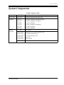
System Components
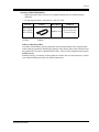
System Components Table
Model
Description
Service Unit
KX-TA1232
Advanced Hybrid System (Main Unit)
Telephone
KX-T7135
KX-T7130
KX-T7020
KX-T7030
KX-T7050
KX-T7055
Proprietary telephone with backlit display
Proprietary telephone with display
Proprietary telephone
Proprietary telephone with display
Proprietary telephone
Proprietary telephone
Optional
Equipment
KX-T7040
DSS Console
KX-TA123260
KX-TA123270
KX-TA123280
KX-TA123291
KX-TA123293
Doorphone / Door Opener Interface Card
8 Extension Expansion Unit
4 CO Line Expansion Unit
DISA Card
Caller ID Card
KX-T30865
Doorphone
Installation Manual
3
Important Safety Instructions
Important Safety Instructions
When using your telephone equipment, basic safety precautions should always be followed to
reduce the risk of fire, electric shock and injury to persons, including the following:
a) Read and understand all instructions.
b) Follow all warnings and instructions marked on the product.
c) Unplug this product from the wall outlet before cleaning. Do not use liquid cleaners or
aerosol cleaners. Use a damp cloth for cleaning.
d) Do not use this product near water, for example, near a bathtub, wash bowl, kitchen sink,
or laundry tub, in a wet basement, or near a swimming pool.
e) Do not place this product on an unstable cart, stand, or table. The product may fall,
causing serious damage to the product.
f) Slots and openings in the cabinet and the back or bottom are provided for ventilation, to
protect it from overheating, these openings must not be blocked or covered. The
openings should never be blocked by placing the product on the bed, sofa, rug, or other
similar surface. This product should never be placed near or over a radiator or heat
register. This product should not be placed in a built-in installation unless proper
ventilation is provided.
g) This product should be operated only from the type of power source indicated on the
marking label. If you are not sure of the type of power supply to your home, consult your
dealer or local power company.
h) This product is equipped with a three wire grounding type plug, a plug having a third
(grounding) pin. This plug will only fit into a grounding type power outlet. This is a
safety feature. If you are unable to insert the plug into the outlet, contact your electrician
to replace your obsolete outlet. Do not defeat the safety purpose of the grounding type
plug.
i) Do not allow anything to rest on the power cord. Do not locate this product where the
cord will be abused by people walking on it.
j) Do not overload wall outlets and extension cords as this can result in the risk of fire or
electric shock.
k) Never push objects of any kind into this product through cabinet slots as they may touch
dangerous voltage points or short out parts that could result in a risk of fire or electric
shock. Never spill liquid of any kind on the product.
l) To reduce the risk of electric shock, do not disassemble this product, but take it to a
qualified serviceman when some service or repair work is required. Opening or
removing covers may expose you to dangerous voltages or other risks. Incorrect
reassembly can cause electric shock when the appliance is subsequently used.
m)Unplug this product from the wall outlet and refer servicing to qualified service
personnel under the following conditions:
1) When the power supply cord or plug is damaged or frayed.
2) If liquid has been spilled into the product.
3) If the product has been exposed to rain or water.
4
Installation Manual
Important Safety Instructions
4) If the product does not operate normally by following the operating instructions.
Adjust only those controls, that are covered by the operating instructions because
improper adjustment of other controls may result in damage and will often require
extensive work by a qualified technician to restore the product to normal operation.
5) If the product has been dropped or the cabinet has been damaged.
6) If the product exhibits a distinct change in performance.
n) Avoid using a telephone (other than a cordless type) during an electrical storm. There
may be a remote risk of electric shock from lightning.
o) Do not use the telephone to report a gas leak in the vicinity of the leak.
SAVE THESE INSTRUCTIONS
Installation Manual
5
Attention
Attention
• Keep the unit away from heating appliances and electrical noise generating devices such as
fluorescent lamps, motors and televisions. These noise sources can interfere with the
performance of the Advanced Hybrid System.
• This unit should be kept free of dust, moisture, high temperature (more than 40 °C / 104 °F)
and vibration, and should not be exposed to direct sunlight.
• Never attempt to insert wires, pins, etc. into the vents or other holes of this unit.
• If there is any trouble, disconnect the unit from the telephone line. Plug the telephone
directly into the telephone line. If the telephone operates properly, do not reconnect the unit
to the line until the trouble has been repaired by an authorized Panasonic Factory Service
Center. If the telephone does not operate properly, chances are that the trouble is in the
telephone system, and not in the unit.
• Do not use benzine, thinner, or the like, or any abrasive powder to clean the cabinet. Wipe
it with a soft cloth.
WARNING
THIS UNIT MAY ONLY BE INSTALLED AND SERVICED BY QUALIFIED
SERVICE PERSONNEL.
WHEN A FAILURE OCCURS WHICH RESULTS IN THE INTERNAL PARTS
BECOMING ACCESSIBLE, DISCONNECT THE POWER SUPPLY CORD
IMMEDIATELY AND RETURN THIS UNIT TO YOUR DEALER.
DISCONNECT THE TELECOM CONNECTION BEFORE DISCONNECTING THE
POWER CONNECTION PRIOR TO RELOCATING THE EQUIPMENT, AND
RECONNECT THE POWER FIRST.
THIS UNIT IS EQUIPPED WITH AN EARTHING CONTACT PLUG. FOR SAFETY
REASONS THIS PLUG MUST ONLY BE CONNECTED TO AN EARTHING
CONTACT SOCKET WHICH HAS BEEN INSTALLED ACCORDING TO
REGULATIONS.
TO PREVENT FIRE OR SHOCK HAZARD, DO NOT EXPOSE THIS PRODUCT TO
RAIN OR MOISTURE.
6
Installation Manual
Attention
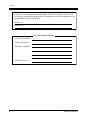
Accessory Order Information
• Replacement parts and accessories are available through your local authorized parts
distributor.
• For ordering accessories, call toll free: 1-800-332-5368.
Part No.
Picture
KX-J07W/B
KX-J15W/B
KX-J25W/B
W:White
Description
Handset cord
Comment
213.36 cm (7 feet)
457.2 cm (15 feet)
762 cm (25 feet)
B:Black
When you ship the product
Carefully pack and send it prepaid, adequately insured and preferably in the original carton.
Attach a postage-paid letter, detailing the symptom, to the outside of the carton. DO NOT send
the product to the Executive or Regional Sales offices. They are NOT equipped to make repairs.
Product service
Panasonic Factory Servicenters for this product are listed in the servicenter directory. Consult
your authorized Panasonic dealer for detailed instructions.
Installation Manual
7
Attention
The serial number of this product may be found on the label affixed to the bottom
of the unit. You should note the model number and the serial number of this unit in
the space provided and retain this book as a permanent record of your purchase to aid
in identification in the event of theft.
MODEL NO.:
SERIAL NO.:
For your future reference
DATE OF PURCHASE
NAME OF DEALER
DEALER’S ADDRESS
DEALER’S TEL NO.
8
Installation Manual
Telephone Company and F.C.C. Requirements and Responsibilities
Telephone Company and F.C.C. Requirements
and Responsibilities
1. Notification to the Telephone Company
Customers, before connecting terminal equipment to the telephone network, shall upon
request of the Telephone Company, inform the Telephone Company of the particular line(s)
to which such connection is made, the F.C.C. registration number (see the label on the
bottom of the unit) and ringer equivalence number (REN) of the registered terminal
equipment.
The REN is useful to determine the quantity of devices you may connect to your telephone
line and still have all of those devices ring when your telephone number is called. In most,
but not all areas, the sum of the REN's of all devices connected to one line should not exceed
five (5.0). To be certain of the number of devices you may connect to your line, as
determined by the REN, you should contact your local telephone company to determine the
maximum REN for your calling area.
2. Connection to Telephone Line
This unit must not be connected to a coin operated line. If you are on a party line, check
with your local telephone company.
3. Incidence of Harm to the Telephone Lines
Should terminal equipment cause harm to the telephone network, the telephone company
shall, where practical, notify the customer that temporary discontinuance of service may be
required.
However, where prior notice is not practical, the telephone company may temporarily
discontinue service forthwith, if such action is reasonable in the circumstances. In case of
such unnotified temporary discontinuance of service, the telephone company shall:
1) Promptly notify the customer of such temporary discontinuance of service.
2) Afford the customer the opportunity to correct the situation which gave rise to the
temporary discontinuance.
3) Inform the customer of the right to bring a complaint to the Federal Communication
Commission pursuant to the procedures set out in Subpart E of Part 68 of FCC
Telephone Equipment Rules.
4. Compatibility of the Telephone Network and Terminal Equipment
a) Availability of telephone interface information.
Technical information concerning interface parameters and specifications not specified
in FCC Rules, including the number of Ringers which may be connected to a particular
telephone line, which is needed to permit Terminal Equipment to operate in a manner
compatible with Telephone Company communications facilities, shall be provided by
the Telephone Company upon customer's request.
b) Changes in Telephone Company Communications Facilities, Equipment,
Operations and Procedures.
The Telephone Company may make changes in its communications facilities,
equipment, operations or procedures, where such action is reasonably required in the
operation of its business and is not inconsistent with the rules and regulations in FCC
Part 68.
Installation Manual
9
Telephone Company and F.C.C. Requirements and Responsibilities
If such changes can be reasonably expected to render any customer Terminal Equipment
incompatible with Telephone Company Communications Facilities, or require
modification or alteration of such Terminal Equipment, or otherwise materially affect its
use or performance, the customer shall be given adequate notice in writing, to allow the
customer an opportunity to maintain uninterrupted service.
Notify the Telephone Company
Installation must be performed by a qualified professional installer. If required, provide the
telephone company with the following technical information:
• Telephone numbers to which the system will be connected
• Make: Panasonic
• Model: KX-TA1232
• FCC Registration No.: found on the bottom of the unit
• Ringer Equivalence No.: 0.4B
• Facility Interface Code: 02LS2, 02RV2-T, 02IS5
• Service Order Code: 9.0F, AS.2, 6.0P
• Required Network Interface Jack: RJ11 / 14C, RJ49
Note
This equipment has been tested and found to comply with the limits for a Class A digital
device, pursuant to Part 15 of the FCC Rules. These limits are designed to provide reasonable
protection against harmful interference when the equipment is operated in a commercial
environment. This equipment generates, uses, and can radiate radio frequency energy and, if
not installed and used in accordance with the instruction manual, may cause harmful
interference to radio communications. Operation of this equipment in a residential area is likely
to cause harmful interference in which case the user will be required to correct the interference
at his own expense.
CAUTION
Any changes or modifications not expressly approved by the party responsible for compliance
could void the user's authority to operate this device.
When programming emergency numbers and / or making test calls to emergency numbers:
1. Remain on the line and briefly explain to the dispatcher the reason for the call before
hanging up.
2. Perform such activities in the off-peak hours, such as early morning hours or late evenings.
10
Installation Manual
Introduction
Introduction
This Installation Manual provides technical information for the Panasonic Advanced Hybrid
System, KX-TA1232. It is designed to serve as an overall technical reference for the system
and includes a description of the system, its hardware and software, features and services and
environmental requirements.
This manual contains the following sections:
Section 1, System Outline
Provides general information on the system including system capacity and specifications.
Section 2, General Installation
Contains the basic system installation and wiring instructions, as well as how to install the
optional cards and units.
Section 3, Troubleshooting
Provides information for system and telephone troubleshooting.
Section 4, Index
Provides the important words and phrases to help you access the required information easily.
Terms used in this Installation Manual
Programming Guide References
The related and required programming titles described in the Programming Guide are noted for
your reference.
Programming Guide reference is also shown in the sentences as follows.
Example: <SYS PRG [109]>
Explanation: Refer to system program [109] in the Programming Guide.
This helps you know the related and required programming easily for the contents of the
sentences.
Features Guide References
The related feature titles described in the Features Guide are noted for your reference.
About the other manuals
Along with this Installation Manual, the following manuals are available to help you know the
available features, program and use the KX-TA1232 system.
Features Guide
Provides information about the system features.
Programming Guide
Provides system programming instructions.
User Manual
Provides operating instructions for the end users using proprietary telephones, single line
telephones, consoles.
Installation Manual
11
Table of Contents
Table of Contents
1
System Outline
1.1 System Highlights ........................................................................................................ 16
1.1.1 System Highlights ...................................................................................................... 16
1.2 Basic System Construction ......................................................................................... 18
1.2.1 Basic System Construction......................................................................................... 18
1.2.2 System Connection Diagram ...................................................................................... 19
1.3 Proprietary Telephones ............................................................................................... 21
1.3.1 Proprietary Telephones ............................................................................................... 21
1.4 Options.......................................................................................................................... 22
1.4.1 Options ....................................................................................................................... 22
1.5 Specifications................................................................................................................ 23
1.5.1 General Description.................................................................................................... 23
1.5.2 Characteristics ............................................................................................................ 24
1.5.3 System Capacity ......................................................................................................... 25
2
General Installation
2.1 Before Installation ....................................................................................................... 28
2.1.1 Before Installation ...................................................................................................... 28
2.2 Installation of the Main Unit ...................................................................................... 30
2.2.1 Unpacking................................................................................................................... 30
2.2.2 Location of Interfaces ................................................................................................. 31
2.2.3 Wall Mounting ............................................................................................................ 32
2.2.4 Opening Front Cover .................................................................................................. 34
2.2.5 Frame Ground Connection ......................................................................................... 35
2.3 Connection.................................................................................................................... 37
2.3.1 Outside Line Connection ............................................................................................ 37
2.3.2 Extension Connection................................................................................................. 38
2.3.3 Telephone Connection ................................................................................................ 43
2.3.4 Polarity Sensitive Telephone Connection ................................................................... 45
2.3.5 External Pager (Paging Equipment) Connection........................................................ 47
2.3.6 External Music Source Connection ............................................................................ 48
2.3.7 Printer and PC Connection ......................................................................................... 50
2.3.8 Installation of Lightning Protectors............................................................................ 54
2.4 Installation of Optional Cards and Units .................................................................. 57
2.4.1 Location of Optional Cards and Units........................................................................ 57
2.4.2 4 CO Line Expansion Unit Connection...................................................................... 60
2.4.3 8 Extension Expansion Unit Connection.................................................................... 61
2.4.4 Installing Expansion Unit ........................................................................................... 62
2.4.5 DISA Card Installation ............................................................................................... 70
2.4.6 Caller ID Card Installation ......................................................................................... 71
2.4.7 Doorphone and Door Opener Connection .................................................................. 73
2.5 Auxiliary Connection for Power Failure Transfer.................................................... 79
2.5.1 Auxiliary Connection for Power Failure Transfer ...................................................... 79
2.6 Closing the Front Cover.............................................................................................. 80
2.6.1 Closing the Front Cover.............................................................................................. 80
2.7 Starting the System for the First Time ...................................................................... 82
12
Installation Manual
Table of Contents
2.7.1 Starting the System for the First Time ........................................................................82
2.8 System Restart ..............................................................................................................84
2.8.1 System Restart.............................................................................................................84
2.9 System Data Clear ........................................................................................................85
2.9.1 System Data Clear .......................................................................................................85
3
Troubleshooting
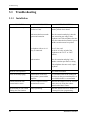
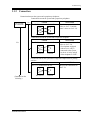
3.1 Troubleshooting ............................................................................................................88
3.1.1 Installation ...................................................................................................................88
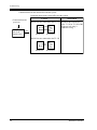
3.1.2 Connection ..................................................................................................................89
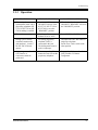
3.1.3 Operation .....................................................................................................................91
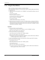
3.1.4 Using the Reset Button................................................................................................92
Index .......................................................................................................95
Installation Manual
13
Table of Contents
14
Installation Manual
System Outline
Section 1
System Outline
This section provides general information on the
system, including system capacity and specifications.
Installation Manual
15
System Outline
1.1
System Highlights
1.1.1
System Highlights
System Maximum Capacity
KXTA1232
Extension
PT&SLT
32
Outside
Line
Analog
12
Module Expansion
Expansion modules are used to increase the system capacity.
Paralleled Telephone Connection
Every jack in the system also supports the parallel connection of a proprietary telephone and a
single line device. They share the same extension number and are considered by the system to
be one extension.
Advanced Hybrid System
This system supports the connection of analog proprietary telephones, a DSS Console and
single line devices such as single line telephones, fax machines, and data terminals.
Analog Proprietary Telephones (APT)
The system supports six different models of analog proprietary telephones.
Programming System
The system can be programmed from a proprietary telephone.
Voice Mail Integration
The system supports Voice Processing Systems with in-band DTMF signaling as well as DPT
integration. The Panasonic Voice Processing System provides automated attendant, voice mail,
interview and custom services.
16
Installation Manual
System Outline
Caller ID
Allows the user to see the name or telephone number of a caller on the telephone display before
answering a call.
Trunk (Outside Line) Answer From Any Station (TAFAS)
Ringing occurs over the external paging system; the call can be answered from any station.
Remote Station Lock Control
Allows an operator to lock an extension so that outgoing calls cannot be made.
Installation Manual
17
System Outline
1.2
Basic System Construction
1.2.1
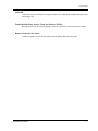
Basic System Construction
The KX-TA1232 Advanced Hybrid System has a basic capacity of eight outside lines and 16
extensions. It is capable of supporting Panasonic analog proprietary telephones, a DSS Console
and single line devices such as single line telephones and fax machines.
To expand its capabilities, the system can be equipped with optional components or customersupplied peripherals such as external speakers and external music sources (e.g., radios).
A1232
ADVANCED
HYBRID SYST
EM KX-TA123
2
Panaso
nic
18
Installation Manual
System Outline
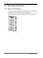
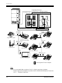
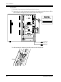
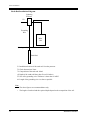
1.2.2
System Connection Diagram
A1232
ADVANCED
HYBRID SYST
EM KX-TA123
2
Printer or PC for SMDR (Station Message Detail Recording)
AC Surge Protector
Panaso
nic
120 V AC, 60 Hz
External Music Source 1
External Music Source 2
Installation Manual
Avoid using the same AC
outlet for office equipment
and the KX-TA1232. Use a
dedicated AC outlet only.
Amplifier
Speaker 1
Amplifier
Speaker 2
19
System Outline
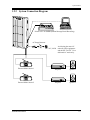
D1232
DEGITAL SUPER HYBRID SYSTEM
12 Outside Lines
(Lightning Protectors)
to outside lines 1 through 8 (initial)
to outside lines 9 through 12 (additional)
Doorphone KX-T30865
Panasonic
Panasonic
Doorphone 1 Doorphone 2
Door Opener 1 Door Opener 2
Panasonic
Panasonic
Panasonic
Doorphone 3 Doorphone 4
Door Opener 3 Door Opener 4
32 Extensions (16 extensions – initial, 16 extensions – additional)
(two pair)
(one
pair)
(one
pair)
(two
pair)
KX-T7020
Single Line Telephone
(one
pair)
Telephone Answering
Machine with Facsimile
KX-T7030
(two pair)
(one pair)
(two
pair)
Pa
nas
oni
c
nic
aso
Pan
Cordless Phone
KX-T7050
Data Terminal
(one
pair)
KX-T7130 / KX-T7135
(two
pair)
(two pair)
Voice Processing System
KX-T7040
KX-T7055
: needs Optional Cards or Adaptor.
Note
• It is recommended that extension of jack 1 is a display proprietary telephone.
• Parallel connection of telephones is possible. Refer to the Paralleled Telephone Connection
in 2.3.3 Telephone Connection.
20
Installation Manual
System Outline
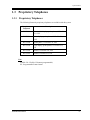
1.3
Proprietary Telephones
1.3.1
Proprietary Telephones
The following Panasonic proprietary telephones are available with this system.
Proprietary
Telephone
Description
KX-T7135
1-line backlit display, speakerphone, 12 Flexible
CO, 12 PF
KX-T7130
1-line display, speakerphone, 12 Flexible CO,
12 PF
KX-T7020
Speakerphone, 12 Flexible CO, 4 PF
KX-T7030
1-line display, speakerphone, 12 Flexible CO,
4 PF
KX-T7050
Monitor, 12 Flexible CO, 4 PF
KX-T7055
Monitor, 3 Flexible CO, 3 PF
Note
Flexible CO : Flexible CO button (programmable)
PF : Programmable Feature button
Installation Manual
21
System Outline
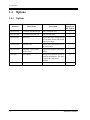
1.4
Options
1.4.1
Options
Model No.
Model Name
Max.
Quantity on
KX-TA1232
Description
KX-TA123270
8 Extension Expansion Unit
Adds 8 extension lines.
2
KX-TA123280
4 CO Line Expansion Unit
Adds 4 outside lines.
1
KX-TA123291
DISA Card
Supports the Direct Inward System
Access (DISA) feature and records
outgoing messages.
1
KX-TA123293
Caller ID Card
Supports the Caller ID Service of
the central office.
3
KX-TA123260
Doorphone / Door Opener
Interface Card
Supports 4 doorphones and 4 door
openers.
1
KX-T7040
DSS Console
Provides easy and quick access to
extensions and features. This must
be used with a proprietary
telephone.
4
KX-T30865
Doorphone
Used for a doorphone call.
4
22
Installation Manual
System Outline
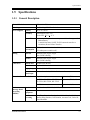
1.5
Specifications
1.5.1
General Description
Control Method
CPU: 16-bit CPU
Switching
Non Blocking PCM Time Switch
Power Supplies
Primary
120 V AC, 60 Hz
Secondary
Station Supply Volt: 30 V
Circuit Volt: 5 V, 15 V
Power Failure • Memory backup duration: seven years with the factory-provided
lithium battery
• 3 outside lines max. for KX-TA1232 automatic transfer to
extensions (Power Failure Transfer)
Dialing
Connectors
Power
Consumption
87 W (under maximum load conditions)
0 W (when power switch is off)
Outward
Dial Pulse (DP) 10 pps, 20 pps
Tone (DTMF) Dialing
Internal
Dial Pulse (DP) 10 pps, 20 pps
Tone (DTMF) Dialing
Outside lines
Modular Jack (RJ14C)
Extensions
Amphenol Connector
Paging Output Pin Jack (RCA JACK)
External
Music Input
Extension Connection Cable
Station
Message Detail
Recording
(SMDR)
Two-conductor Jack (MINIJACK 3.5 mm diameter)
Single line telephones
1 pair wire (T, R)
KX-T7135, KX-T7130, KX-T7020,
KX-T7030, KX-T7050, KX-T7055
2 pair wire (T, R, L, H)
KX-T7040
1 pair wire (L, H)
Interface
Serial Interface (RS-232C) (D-SUB, 25-pin)
Output
Equipment
Printer
Detail
Recording
Date, Time, Extension Number, Outside Line Number, Dialed
Number, Ring Duration, Call Duration, Account Code, Caller ID,
Timed Reminder
Installation Manual
23
System Outline
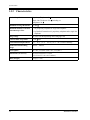
1.5.2
Characteristics
Station Loop Limit
Proprietary Telephone: 40
Single Line Telephone: 600
Doorphone: 20
including set
Minimum Leakage Resistance
15 000
Maximum Number of Station
Instruments per Line
1 for proprietary telephone or single line telephone
Ring Voltage
70 Vrms at 20 Hz depending on the Ringing Load
Central Office Loop Limit
1 600
Environmental Requirements
0 °C – 40 °C (32 °F – 104 °F), 10 % – 90 % relative humidity
Hookswitch Flash Timing
Range
200 ms – 1000 ms
Door Opener
30 V DC, 5 A (Max.)/250 V AC, 5 A (Max.)
Dimensions (W x H x D)
325 mm x 640 mm x 115 mm
(12-13/16 x 25-3/16 x 4-1/2 inches)
Mass (Weight)
7.8 kg (17.2 lb)
24
2 by Parallel Connection of a proprietary telephone and a single line
telephone
max.
Installation Manual
System Outline
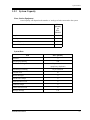
1.5.3
System Capacity
Lines, Station Equipment
Actual capacity will depend on the number or / and type of units connected to the system.
Item
Max.
Quantity
on
KXTA1232
Doorphones
4
Door Openers
4
External Pagers
2
External Music Sources
2
System Data
Item
Operators
System Speed Dialing
One-Touch Dialing
Personal Speed Dialing
Max. Quantity
2
500
24 per extension
(proprietary telephone)
10 per extension
Call Park areas
10
Absent Messages
9
Outside Line Groups
8
Toll Restriction Levels
8
Extension Groups
8
Class of Service levels
8
Message Waitings
Installation Manual
128
25
System Outline
26
Installation Manual
General Installation
Section 2
General Installation
Installation Manual
27
General Installation
2.1
Before Installation
2.1.1
Before Installation
Please read the following notes concerning installation and connection before installing the
system and terminal equipment.
Safety Installation Instructions
When installing telephone wiring, basic safety precautions should always be followed to
reduce the risk of fire, electric shock and injury to persons, including the following:
a) Never install telephone wiring during a lightning storm.
b) Never install telephone jacks in wet locations unless the jack is specifically designed for
wet locations.
c) Never touch uninsulated telephone wires or terminals unless the telephone line has been
disconnected at the network interface.
d) Use caution when installing or modifying telephone lines.
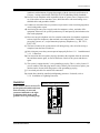
Installation Precautions
This system is designed for wall mounting only. Avoid installing in the following places.
(Doing so may result in malfunction, noise, or discoloration.)
a) In direct sunlight and hot, cold, or humid places. (Temperature range: 0 °C – 40 °C / 32
°F – 104 °F)
b) Sulfuric gases produced in areas where there are thermal springs, etc. may damage the
equipment or contacts.
c) Places in which shocks or vibrations are frequent or strong.
d) Dusty places, or places where water or oil may come into contact with the system.
e) Near high-frequency generating devices such as sewing machines or electric welders.
f) On or near computers, telexes, or other office equipment, as well as microwave ovens or
air conditioners. (It is preferable not to install the system in the same room with the
above equipment.)
g) Install at least 1.8 m (6 feet) away from radios and televisions. (Both the system and
Panasonic proprietary telephones)
h) Do not obstruct area around the system (for reasons of maintenance and inspection —
be especially careful to allow space for cooling above and at the sides of the system).
Wiring Precautions
Be sure to follow these instructions when wiring the unit:
a) To assure good quality telephone connection, it is recommended new and modifications
to existing installation of customer premise wiring shall use solid twisted pair copper
28
Installation Manual
General Installation
conductors with minimum 24 gauge that comply with the electrical specifications for
Category 3 wiring as detailed in ANSI/EIA/TIA-570A Building Wiring Standards.
b) Do not wire the telephone cable in parallel with an AC power source, computer, telex,
etc. If the cables are run near those wires, shield the cables with metal tubing or use
shielded cables and ground the shields.
c) If cables are run on the floor, use protectors to prevent the wires from being stepped on.
Avoid wiring under carpets.
d) Avoid using the same power supply outlet for computers, telexes, and other office
equipment. Otherwise, the system operation may be interrupted by the induction noise
from such equipment.
e) Please use one pair telephone wire for extension connection of (telephone) equipment
such as single line telephones, data terminals, answering machines, computers, voice
processing systems, etc., except Panasonic proprietary telephones (e.g., KX-T7135,
KX-T7130).
f) The Power Switch of the system must be off during wiring. After all of the wiring is
completed, turn the Power Switch on.
g) Mis-wiring may cause the system to operate improperly. Refer to 3.1.1 Installation and
3.1.2
Connection.
h) If an extension does not operate properly, disconnect the telephone from the extension
line and then connect again, or turn off the Power Switch of the system and then on
again.
i) The system is equipped with a 3-wire grounding type plug. This is a safety feature. If
you are unable to insert the plug into the outlet, contact your electrician to replace your
obsolete outlet. Do not defeat the purpose of the grounding-type plug.
j) Use twisted pair cable for outside line connection.
k) Outside lines should be installed with lightning protectors. For details, refer to
2.3.8
Installation of Lightning Protectors.
WARNING
Warning: Static sensitive connectors
Static sensitive devices are used. To
protect printed circuit boards from
static electricity, do not touch
connectors indicated to the right.
To discharge body static, touch
ground or wear a grounding strap.
DISA
DOORPHONE
Installation Manual
29
General Installation
2.2
Installation of the Main Unit
2.2.1
Unpacking
Unpack the box and check the items below:
KX-TA1232
30
Main Unit
one
AC Cord
one
Template
one
Screws (Wall Mounting)
four
Pager Connectors
two
Music Source Connectors
two
Expansion Line Cord Holder
one
Installation Manual
General Installation
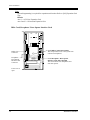
2.2.2
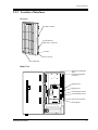
Location of Interfaces
Overview
A1232
ADVANCED
HYBRID SYST
EM KX-TA123
2
Ground Terminal
Serial Interface
(RS-232C) Connector
Panaso
nic
AC Inlet
Power Switch
Power Indicator
Inside View
Outside Line Modular
Jacks
Extension Amphenol
Connector
Paging Jack 2
Paging Jack 1
External Music Jack 2
External Music Jack 1
DISA
System Clear Switch
DOORPHONE
Installation Manual
Reset Button
31
General Installation
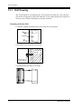
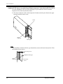
2.2.3
Wall Mounting
This set is designed for wall mounting only. The wall where the main unit is to be mounted
must be able to support the weight of the main unit. If screws other than the ones supplied are
used, use screws with the same diameter as the ones enclosed.
Mounting on Wooden Wall
1. Place the template (included) on the wall to mark the screw positions.
Template
2. Install the screws (included) into the wall.
Wooden
Wall
Drive the screw
to this position
3. Hook the main unit on the screw heads.
32
Installation Manual
General Installation
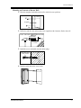
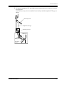
Mounting on Concrete or Mortar Wall
1. Place the template (included) on the wall to mark the screw positions.
Template
2. Drill holes and drive the anchor plugs (user-supplied) with a hammer, flush to the wall.
To the wall surface
Concrete Wall
Anchor Plug
6.4 mm
(1/4 inch)
29 mm
(1-1/8 inch)
3. Install the screws (included) into the anchor plugs.
Drive the screw
to this position
4. Hook the main unit on the screw heads.
Installation Manual
33
General Installation
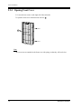
2.2.4
Opening Front Cover
1. Loosen the two screws on the right side of the main unit.
2. Open the front cover in the direction of arrow A .
A1232
ADVANCED
HYBRID SYSTE
M KX-TA1232
D816
DIGITAL SUPE
A
R HYBRID SYSTE
screw
M
screw
A
screw
screw
Panas
Pan
aso
oni
nicc
Note
The two screws are attached to the front cover with springs so that they will not be lost.
34
Installation Manual
General Installation
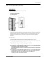
2.2.5
Frame Ground Connection
IMPORTANT
Connect the frame of the main unit to ground.
1.
2.
3.
4.
Loosen the screw.
Insert the grounding wire.
Tighten the screw.
Connect the grounding wire to ground.
A1232
ADVANCED
HYBRID SYSTE
M KX-TA1232
D816
DIGITAL SUPE
R HYBRID SYSTE
M
To ground
Panas
onic
To ground
In most of the continental United States, the ground provided by the "Third wire ground" at the
commercial power outlet will be satisfactory. However, in a small percentage of cases this
ground may be installed incorrectly. Therefore, the following test procedure should be
performed.
Test Procedure
1. Obtain a suitable voltmeter and set it for a possible reading of up to 250 V AC.
2. Connect the meter probes between the two main AC voltage points on the wall outlet. The
reading obtained should be 108 V AC-132 V AC.
3. Move one of the meter probes to the 3rd prong terminal (GND).
Either the same reading or a reading of 0 V should be obtained.
4. If a reading of 0 V at one terminal and a reading of 108 V AC-132 V AC at the other terminal
is not obtained, the outlet is not properly grounded.
This condition should be corrected by a qualified electrician (per article 250 of the National
Electrical Code).
5. If a reading of 0 V at one terminal and a reading of 108 V AC-132 V AC at the other terminal
is obtained, then set the meter to the "OHMS / RX1" scale, place one probe at the GND
Terminal and the other probe at the terminal which gave a reading of 0 V.
A reading of less than 1 ohm should be obtained.
Installation Manual
35
General Installation
If the reading is not obtained the outlet is not adequately grounded, see a qualified
electrician.
36
Installation Manual
General Installation
2.3
Connection
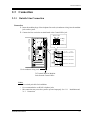
2.3.1
Outside Line Connection
Connection
1. Insert the modular plugs of the telephone line cords (4-conductor wiring) into the modular
jacks on the system.
2. Connect the line cord to the terminal board or the Central Office jack.
T2 R1 T1 R2
R: Ring
T: Tip
View of TEL Jack (Outside Line)
(T1, R1)
(T2, R2)
Outside Line 7, Outside Line 8
DISA
Outside Line 5, Outside Line 6
DOORPHONE
Outside Line 3, Outside Line 4
Outside Line 1, Outside Line 2
Use 4-conductor wiring cord
To Terminal Board or Modular
Jacks from the Central Office.
Notice
• Use twisted pair cable for installation.
• It is recommended to use RJ14C telephone jacks.
• Mis-connection may cause the system to operate improperly. See 3.1.1
3.1.2 Connection.
Installation Manual
Installation and
37
General Installation
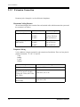
2.3.2
Extension Connection
Extension jacks 1 through 16 are for all kinds of telephones.
Maximum Cabling Distance
The maximum length of the extension line cord (twisted cable) which connects the system and
the extension is as follows:
Diameter of the line
Max. length
Single Line Telephone
22 AWG
24 AWG
26 AWG
1798 m (5900 feet)
1128 m (3700 feet)
698 m (2290 feet)
Proprietary Telephone /
DSS Console
22 AWG
24 AWG
26 AWG
360 m (1180 feet)
229 m (750 feet)
140 m (460 feet)
Telephone Wiring
2 or 4-conductor wiring is required for each extension as listed below. There are four pins for
possible connection: "T", "R", "L" and "H".
T:Tip
R:Ring
L:Low
H:High
Telephone
38
Wiring
Single line telephones wiring
1 pair wire (T, R)
Analog proprietary telephone
(KX-T7135, KX-T7130, KXT7020, KX-T7030, KX-T7050,
KX-T7055)
2 pair wire (L, H, T, R)
DSS console
(KX-T7040)
2 pair wire (L, H)
Installation Manual
General Installation
* 2-pair twisted cabling:
Block Terminal
50-Pin Connector
26
1
1
1
2
2
27
3
3
2
4
4
28
5
5
3
6
6
Green
Red
Black
Yellow
Line cord
6
5
4
3
2
1
White
Blue
Bridging Clips
Installation Manual
39
General Installation
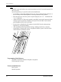
Connection
1. Insert the 50-pin connector to the Extension Jack as shown.
2. Connect the wire cords to the appropriate connector pins and the terminal equipment. Refer
to the Telephone Wiring (Page 38) and Pin Number Chart (Page 41).
Connector type
50-pin (Amphenol 57JE
series or the equivalent)
25
1
50
26
DISA
DOORPHONE
To extensions
(Jacks 9-16)
To extensions
(Jacks 1-8)
3. After inserting the connector, fasten the connector with the nylon tie.
40
Installation Manual
General Installation
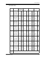
Pin Number Chart
Pin no. Cable Color
26
1
27
2
WHT-BLU
BLU-WHT
WHT-ORN
ORN-WHT
29
4
30
5
WHT-BRN
BRN-WHT
WHT-SLT
SLT-WHT
32
7
33
8
RED-ORN
ORN-RED
RED-GRN
GRN-RED
35
10
36
11
RED-SLT
SLT-RED
BLK-BLU
BLU-BLK
38
13
39
14
BLK-GRN
GRN-BLK
BLK-BRN
BRN-BLK
41
16
42
17
YEL-BLU
BLU-YEL
YEL-ORN
ORN-YEL
44
19
45
20
YEL-BRN
BRN-YEL
YEL-SLT
SLT-YEL
47
22
48
23
VIO-ORN
ORN-VIO
VIO-GRN
GRN-VIO
EXTN. 1-8 /
Doorphone
EXTN. 9-16
Jack
No.1
T
R
L
H
Jack
No.9
T
R
L
H
Jack
No.2
T
R
L
H
Jack
No.10
T
R
L
H
Jack
No.3
T
R
L
H
Jack
No.11
T
R
L
H
Jack
No.4
T
R
L
H
Jack
No.12
T
R
L
H
Jack
No.5
T
R
L
H
Jack
No.13
T
R
L
H
Jack
No.6
T
R
L
H
Jack
No.14
T
R
L
H
Jack
No.7
T
R
L
H
Jack
No.15
T
R
L
H
Jack
No.8
T
R
L
H
Jack
No.16
T
R
L
H
8EXTN.*
Jack
No.17
T
R
L
H
Jack
No.18
T
R
L
H
Jack
No.19
T
R
L
H
Jack
No.20
T
R
L
H
Jack
No.21
T
R
L
H
Jack
No.22
T
R
L
H
Jack
No.23
T
R
L
H
Jack
No.24
T
R
L
H
8EXTN.*
Jack
No.25
T
R
L
H
Jack
No.26
T
R
L
H
Jack
No.27
T
R
L
H
Jack
No.28
T
R
L
H
Jack
No.29
T
R
L
H
Jack
No.30
T
R
L
H
Jack
No.31
T
R
L
H
Jack
No.32
T
R
L
H
50
25
Installation Manual
41
General Installation
Note
*"8EXTN" in the table indicates an extension expansion area for 8 Extension Expansion Unit
(KX-TA123270).
System Programming is required for card location identification.
• If a telephone or answering machine with an A-A1 relay is connected to the main unit, set
the A-A1 relay switch of the telephone or answering machine to OFF position.
• Mis-connection may cause the system to operate improperly. See 3.1.1 Installation and
3.1.2 Connection.
• A DSS Console (KX-T7040) can be installed. As the DSS Console itself cannot work alone,
it always requires a proprietary telephone used in pair. Place the DSS Console and the
paired telephone side by side on your desk.
• It is necessary to designate the jack numbers of paired DSS Consoles and proprietary
telephones by system programming.
• After completing all the required inside cabling, including outside lines, extensions,
external pagers, external music sources, doorphones and door openers, fasten the cables
with the nylon tie (included) as shown.
Programming Guide Reference
[007] DSS Console Port and Paired Telephone Assignment
[109] Expansion Unit Type
Features Guide Reference
DSS Console
Module Expansion
42
Installation Manual
General Installation
2.3.3
Telephone Connection
Proprietary Telephone / DSS Console Connection
Connect proprietary telephones and a DSS Console as follows:
Analog Proprietary Telephone
Included telephone
line cord
Connect to an Advanced Hybrid System
(TO EMSS).
ic
n
o
s
a
n
a
P
KX-T7040 DSS Console
ZE ZUR
NT
RA
LE
Included telephone
line cord
Connect to an Advanced
Hybrid System (TO EMSS).
Installation Manual
43
General Installation
Paralleled Telephone Connection
Any single line telephone can be connected in parallel with a proprietary telephone as follows:
Method: Using a Modular T-Adaptor
Any single line telephone can be connected in parallel with a proprietary telephone as follows:
A1232
ADVANCED
HYBRID SYSTE
M KX-TA1232
Modular T-Adaptor
(Panasonic KX-J66 or USOC RJA2X)
2-conductor wiring cord
Connect pins “T” and “R”.
4-conductor wiring cord
For APT: Connect pins “T2”, “R”, “L”
and “H”.
Analog Proprietary
Telephone
44
Single Line Telephone
Installation Manual
General Installation
2.3.4
Polarity Sensitive Telephone Connection
If your telephone is polarity sensitive, follow the procedure below:
1. Complete all the required extension wiring.
2. Confirm that dialing can be done from all the extensions using a touch-tone telephone. If
dialing fails, the polarity between the extension and the system must be reversed.
3. Reverse as shown.
A1232
ADVANCED
HYBRID SYSTEM
KX-TA1232
Extension
Central Office Line
1
2
3
4
5
7
8
9
0
#
6
Reverse here
4. Set the Power Switch to "OFF" position.
5. Connect all outside lines.
6. Confirm that dialing can be done on the following extensions using a tone telephone.
Extension (T, R) of jack 1: Outside line 1
Extension (T, R) of jack 9: Outside line 3
Extensions (T, R) of jacks 17 (Extension Expansion Unit 1): Outside line 9
If dialing fails, the polarity between the system and the outside line must be reversed.
Installation Manual
45
General Installation
7. Reverse as shown.
A1232
ADVAVNCED
HYBRID SYSTEM
KX-TA1232
Extension
Central Office Line
1
2
3
4
5
7
8
9
0
#
6
Reverse here
8. Every time an extension telephone is replaced, repeat the above procedure.
46
Installation Manual
General Installation
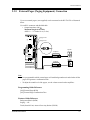
2.3.5
External Pager (Paging Equipment) Connection
Up to two external pagers (user-supplied) can be connected to the KX-TA1232 as illustrated
below.
Use an RCA connector and shielded cable.
• Output impedance: 600
Maximum length of the cable
AWG 18 — 22: Under 10 m (33 feet)
Paging Jack 2
Paging Jack 1
Speaker
Amplifier
DISA
DOORPHONE
Paging Equipment 2
Speaker
Amplifier
Paging Equipment 1
Note
• It is programmable which external pager will send background music and whether all the
pagers will generate a confirmation tone.
• To adjust the sound level of the pagers, use the volume control on the amplifiers.
Programming Guide Reference
[804] External Pager BGM
[805] External Pager Confirmation Tone
Features Guide Reference
Background Music (BGM)
Paging — All
Trunk (Outside Line) Answer From Any Station (TAFAS)
Installation Manual
47
General Installation
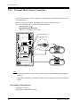
2.3.6
External Music Source Connection
Up to two music sources such as a radio (user-supplied) can be connected to the KX-TA1232
as illustrated below.
Insert the plug to the earphone / headphone jack on the external music source.
Use a two-conductor plug {3.5 mm (9/64 inch) in diameter}.
• Input impedance: 8
Maximum length of the cable
AWG 18 — 22: Under 10 m (33 feet)
External Music Jack 2
External Music Jack 1
DISA
External Music Source 2
DOORPHONE
External Music Source 1
Note
• System Programming of music sources used for Music on Hold and Background Music is
required.
• To adjust the sound level of the Music on Hold, use the volume control on the external music
source.
Programming Guide Reference
[803] Music Source Use
[990] System Additional Information
48
Installation Manual
General Installation
Features Guide Reference
Background Music (BGM)
Background Music (BGM) — External
Music on Hold
Installation Manual
49
General Installation
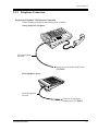
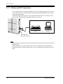
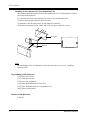
2.3.7
Printer and PC Connection
A user-supplied printer or personal computer (PC) can be connected to the system. These are
used to print out or refer to the Station Message Detail Recording (SMDR) call records and
system programming data.
Connect the printer cable or the PC cable to the Serial Interface (RS-232C) connector. The
cable must be shielded and the maximum length is 2 m (6.5 feet).
Printer
or
Computer
Serial Interface
(RS-232C) (25-pin)
Note
Arrange cables so that the printer will be connected to the system as shown in the chart on the
following page.
When using special accessories such as cable, the user should use those specified in this
installation manual to comply with the limits for a class A digital device pursuant to the FCC
Rules.
50
Installation Manual
General Installation
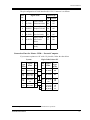
The pin configuration of Serial Interface (RS-232C) Connector is as follows:
Pin
No.
Signal Name
Circuit Type
EIA CCITT
1
2
FG
SD (TXD)
Frame Ground
Transmitted Data
AA
BA
101
103
3
4
RD (RXD)
RS (RTS)
Received Data
Request To Send
BB
CA
104
105
5
6
CS (CTS)
DR (DSR)
Clear To Send
Data Set Ready
CB
CC
106
107
7
8
SG
CD (DCD)
Signal Ground
Data Carrier
Detect
AB
CF
102
109
20
ER (DTR)
Data Terminal
Ready
CD
108.2
Connection Chart for Printer / IBM ® *1 Personal Computer
If you connect a printer or a PC with a 25-pin cable, follow the chart below.
System
*1
25-pin Cable Printer/PC
Circuit
Type
(EIA)
Signal
Name
Pin
No.
Pin
No.
Signal
Name
Circuit
Type
(EIA)
AA
BA
FG
SD (TXD)
1
2
1
3
FG
RD (RXD)
AA
BB
BB
CB
RD (RXD)
CS (CTS)
3
5
2
SD (TXD)
BA
CC
AB
CR (DSR)
SG
6
7
20
7
ER (DTR)
SG
CD
AB
CD
ER (DTR)
20
5
6
8
CS (CTS)
CR (DSR)
CD (DCD)
CB
CC
CF
IBM is a registered trademark of International Business Machines Corporation.
Installation Manual
51
General Installation
If you connect a printer or an IBM-PC with a 9-pin cable, follow the chart below.
System
9-pin Cable Printer/IBM-PC
Circuit
Type
(EIA)
Signal
Name
Pin
No.
Pin
No.
Signal
Name
Circuit
Type
(EIA)
AA
BA
FG
SD (TXD)
1
2
2
RD (RXD)
BB
BB
CA
RD (RXD)
RS (RTS)
3
4
3
4
SD (TXD)
ER (DTR)
BA
CD
CB
CC
CS (CTS)
DR (DSR)
5
6
5
6
SG
DR (DSR)
AB
CC
CB
CC
SG
ER (DTR)
7
20
7
8
RS (RTS)
CS (CTS)
CA
CB
Note
Please read your printer manual and connect the first EIA pin (FG) of this unit to the printer
cable.
Serial Interface (RS-232C) Signals
Frame Ground: FG
Connects to the unit frame and the earth ground conductor of the AC power cord.
Transmitted Data: SD (TXD): (output)
Conveys signals from the unit to the printer. A "Mark" condition is held unless data or BREAK
signals are being transmitted.
Received Data: RD (RXD): (input)
Conveys signals from the printer.
Request to Send: RS (RTS): (output)
This lead is held ON whenever DR (DSR) is ON.
Clear To Send: CS (CTS): (input)
An ON condition of circuit CS (CTS) indicates that the printer is ready to receive data from the
unit. The unit does not attempt to transfer data or receive data when circuit CS (CTS) is OFF.
Data Set Ready: DR (DSR): (input)
An ON condition of circuit DR (DSR) indicates the printer is ready. Circuit DR (DSR) ON does
not indicate that communication has been established with the printer.
Signal Ground: SG
Connects to the DC ground of the unit for all interface signal.
Data Terminal Ready: ER (DTR): (output)
This signal line is turned ON by the unit to indicate that it is ON LINE. Circuit ER (DTR) ON
does not indicate that communication has been established with the printer. It is switched OFF
when the unit is OFF LINE.
52
Installation Manual
General Installation
Data Carrier Detect: CD (DCD): (input)
The ON condition is an indication to data terminal (DTE) that the carrier signal is being
received.
Programming Guide Reference
[800] SMDR Incoming / Outgoing Call Log Printout
[801] SMDR Format
[802] System Data Printout
[806] Serial Interface (RS-232C) Parameters
Features Guide Reference
Station Message Detail Recording (SMDR)
Installation Manual
53
General Installation
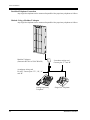
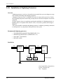
2.3.8
Installation of Lightning Protectors
Overview
A lightning protector is a device to be installed on an outside line to prevent a dangerous surge
from entering the building and damaging equipment.
A dangerous surge can occur if a telephone line comes in contact with a power line. Trouble
due to lightning surges has been showing a steady increase with the development of electronic
equipment.
In many countries, there are regulations requiring the installation of a lightning protector. A
lightning strike to a telephone cable which is 10 m (33 feet) above ground can be as high as
200,000 V.
This system should be installed with lightning protectors. In addition, grounding (connection
to earth ground) is very important for the protection of the system.
Recommended lightning protectors
•
•
•
•
TELESPIKE BLOK MODEL TSB (TRIPPE MFG. CO.)
SPIKE BLOK MODEL SK6-0 (TRIPPE MFG. CO.)
Super MAXTM (PANAMAX)
MP1 (ITW LINK)
Installation
CO
CO
Lightning
Protectors
CO
System
Terminal
Board
EXTN
Ground
Terminal
EXTN
TEL
EXTN
TEL
Frame Ground
Ground
CO: Central Office (Outside line)
EXTN: Extension line
TEL: Telephone
54
Installation Manual
General Installation
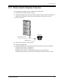
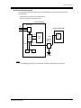
Outside Installation Diagram
If you install an extension outside of the main building, the following precautions are
recommended:
a) Install the extension wire underground.
b) Use a conduit to protect the wire.
(Main Building)
CO
Protectors
(Another Building)
CO
Ter- CO
minal
Board EXTN
EXTN
TEL
Main
Unit
EXTN
SLT
PT
Lightning
Protector
EXTN
TEL
Ground
Note
• The lightning protector for an extension is different from that for outside line.
Installation Manual
55
General Installation
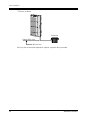
Earth Rod Installation Diagram
Lightning
Protector
CO
Grounding
Wire
Main
Unit
(Underground)
Earth Rod
1.
2.
3.
4.
5.
6.
Installation location of the earth rod: Near the protector
Check obstructions: None
Composition of the earth rod: Metal
Depth of the earth rod: More than 50 cm (20 inches)
Size of the grounding wire: Thickness is more than 16 AWG.
Length of the grounding wire: As short as possible
Note
• The above figures are recommendations only.
• The length of earth rod and the required depth depend on the composition of the soil.
56
Installation Manual
General Installation
2.4
Installation of Optional Cards and Units
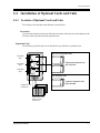
2.4.1
Location of Optional Cards and Units
The location of the optional cards and units is shown below.
Precaution
To protect the printed circuit boards (P-boards) from static electricity, do not touch parts on the
P-boards in the main unit and on the optional cards.
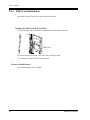
Expansion Units
The following expansion units can be installed to any of the three expansion areas.
Max. two extension line units
Expansion
area 3
8 Extension Expansion Unit,
KX-TA123270
Expansion
area 2
Expansion
area 1
One outside line unit
Panasonic
Expansion Unit
Connectors
4 CO Line Expansion Unit,
KX-TA123280
A1232
Remove the cover
plate(s) on the
front cover.
Installation Manual
57
General Installation
Note
System Programming is required for expansion unit location. Refer to [109] Expansion Unit
Type.
Default:
Area 1 = 4 CO Line Expansion Unit,
Area 2 and 3 = 8 Extension Expansion Unit.
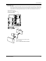
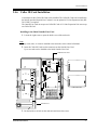
DISA Card, Doorphone / Door Opener Interface Card
DISA Card
Connector
Doorphone /
Door Opener
Interface Card
Connector
DISA
DOORPHONE
Install DISA Card, KX-TA123291.
This card permits access to the system from
outside tone telephones.
Install Doorphone / Door Opener
Interface Card, KX-TA123260.
This card connects four doorphones and
four door openers.
Front Cover is
open.
58
Installation Manual
General Installation
Caller ID Cards
Up to three Caller ID Cards (KX-TA123293) can be installed to the initially provided Outside
Line Card and 4 CO Line Expansion Unit. This card supports Caller ID services offered by the
central office. The initially provided Outside Line Card is located behind the inside cover.
Initial Outside Line Card
Install up to two Caller ID
Cards, KX-TA123293.
Inside cover
4C
O
AD
VA
NC
ED
HY
BR
ID
SY
ST
EM
Installation Manual
4 CO Line Expansion Unit, KX-TA123280
(inside the cabinet)
Install one Caller ID Card, KX-TA123293.
59
General Installation
2.4.2
4 CO Line Expansion Unit Connection
To add four outside lines (outside lines 9 through 12), use the optional 4 CO Line Expansion
Unit (KX-TA123280). This unit can be installed to any of the expansion unit areas provided on
the front of the main unit. For outside line expansion unit installation, see 2.4.4 Installing
Expansion Unit.
Note
• System Programming is required for card location identification.
• If you intend to attach a Caller ID Card to the 4 CO Line Expansion Unit, attach the Caller
ID Card before outside line connection. See 2.4.6 Caller ID Card Installation.
Programming Guide Reference
[109] Expansion Unit Type
Features Guide Reference
Module Expansion
60
Installation Manual
General Installation
2.4.3
8 Extension Expansion Unit Connection
To add eight extensions (jack numbers 17 through 24 or 25 through 32), use the optional 8
Extension Expansion Unit (KX-TA123270). To add 16 extensions (jack numbers 17 through
32), use two 8 Extension Expansion Units.
This unit can be installed to any of the expansion unit areas provided on the front of the main
unit.
For extension expansion unit installation, see 2.4.4 Installing Expansion Unit.
Note
System Programming is required for card location identification.
Programming Guide Reference
[109] Expansion Unit Type
Features Guide Reference
Module Expansion
Installation Manual
61
General Installation
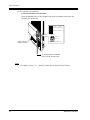
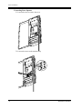
2.4.4
Installing Expansion Unit
The following procedures can be used to install the optional expansion units.
The following steps 1 through 5 and 7 through 10 are the same for all expansion units. Step 6
is different for each unit.
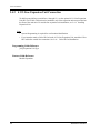
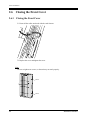
1. Loosen the two screws on the cover plate. Insert fingers into the slits to remove the cover
plate.
A1232
ADVANCED
HYBRID SYSTE
M KX-TA1232
Slit
Slit
Panaso
nic
Note
Any of the cover plates can be removed, as needed.
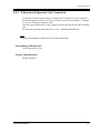
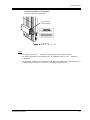
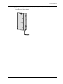
2. Connect the cabinet cord to the connector in the main unit firmly.
A1232
ADVANCED HYBRID SYSTEM KX-TA1232
Panasonic
62
Installation Manual
General Installation
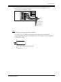
3. Hook the cabinet on the main unit and slide the cabinet to the left until it is secured.
A1232
ADVANCED HYBRID SYSTEM KX-TA1232
Panasonic
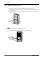
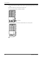
4. Loosen the outside screw and slide the cover to the right.
A1232
ADVANCED HYBRID SYSTEM KX-TA1232
Panasonic
Outside screw
5. Secure the inside screw (included) to fix the cabinet to the main unit.
A1232
ADVANCED HYBRID SYSTEM KX-TA1232
Panasonic
Inside screw
Note
Be sure to fix the inside screw to the main unit, or the unit may not work properly.
Installation Manual
63
General Installation
6. (If a option is to be installed)
If a KX-TA123280 is to be installed;
Insert the modular plugs of the telephone line cords (4-conductor wiring) into the
modular jacks on the unit.
(T1/R1)
(T2/R2)
Outside Line 9, Outside Line 10
4C
Outside Line 11, Outside Line 12
P
FT
O
po
rts
A
D
V
A
N
C
E
D
H
Y
2C
B
R
O
ID
w
/P
S
Y
FT
S
TE
M
T2 R1 T1 R2
2C
O
R: Ring
T: Tip
Jack for Power
Failure Transfer *
View of TEL Jack (Outside Line)
P
an
as
on
ic
To Terminal Board or Modular
Jacks from the Central Office
Note
• * For details, refer to 2.5.1
64
Auxiliary Connection for Power Failure Transfer.
Installation Manual
General Installation
If a KX-TA123270 is to be installed;
Insert the connector into the jack.
Jack for Power
Failure Transfer
8E
PF
T
X
po
rts
T
AD
VA
N
C
ED
H
YB
R
ID
SY
ST
EM
8E
XT
Connector type
50-pin (Amphenol 57JE
series or the equivalent)
25
1
50
26
P
an
as
on
ic
To extensions
(Jacks 17 – 24 or 25 – 32)
Note
• For details, refer to 2.5.1 Auxiliary Connection for Power Failure Transfer.
• For cable pin numbers to be connected, see "Pin Number Chart" in 2.3.2 Extension
Connection.
• For fixing the connector, see "Amphenol 57JE Type (screw-attach-type 50-pin connector)
Connection for KX-TA123270" in 2.4.4 Installing Expansion Unit.
Installation Manual
65
General Installation
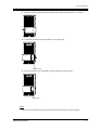
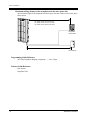
7. Tie all of the cords into a bundle. If other cords are exposed in the upper cabinets, tie them
also.
8. Close the cabinet cover and secure the outside screw.
9. Cover the cords with the cord holder (included).
A1232
ADVANCED HYBRID SYSTEM KX-TA1232
Cord holder
Panasonic
10.Fix the cords to the wall as shown so that the front cover can be opened.
A1232
ADVANCED HYBRID SYSTEM KX-TA1232
Panasonic
66
Installation Manual
General Installation
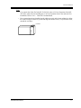
Note
• If you attach the Caller ID Card (KX-TA123293) to the 4 CO Line Expansion Unit (KXA123280), attach it before installing the 4 CO Line Expansion Unit to the main unit. For
installation, Refer to 2.4.6 Caller ID Card Installation.
• If two expansion units are installed, cut the cabinet cover(s) on the lower cabinet(s) to allow
the cords from upper cabinet to go down through the cabinet cover(s). To protect the cords,
smooth the cut edges.
Cut here
Installation Manual
67
General Installation
Amphenol 57JE Type (screw-attach-type 50-pin connector) Connection for KX-TA123270
To fix the Amphenol 57JE type (screw-attach type 50-pin connector) to the 8 Extension
Expansion Unit, follow the procedure below.
1. The 50-pin connector (Jack) on the Expansion Unit has two hook-pins. Remove the upper
hook-pin, and take out the screw.
Screw
8E
XT
AD
VA
NC
ED
HY
BR
ID
SY
ST
EM
50-pin
connector
Hook-pins
Note
When installing a connector like the type shown below, unscrew the lower hook-pin also. Then
drive both accessory screws.
Accessory screw
Amphenol 57JE type
50-pin
connector
68
Accessory
screw
Installation Manual
General Installation
2. To attach the Amphenol 57JE type (Plug) to the connector, drive the accessory screw into
the upper part.
Fasten the accessory wire tie around the lower hook-pin and the Amphenol 57JE type, as
shown.
Accessory screw
Amphenol 57JE type
Accessory wire tie
57JE type
Hook-pin
Accessory
wire tie
Installation Manual
69
General Installation
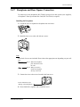
2.4.5
DISA Card Installation
The DISA Card (KX-TA123291) can be installed as follows.
Installing the DISA Card (KX-TA123291)
1. Insert the upper side of the DISA Card into the two hooks on the main unit.
DISA Card
2. Press down the two corners of the lower side of the DISA Card.
3. Connect the cord to the DISA Card Connector.
Features Guide Reference
Direct Inward System Access (DISA)
70
Installation Manual
General Installation
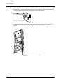
2.4.6
Caller ID Card Installation
A maximum of three Caller ID Cards can be installed. The Caller ID Cards can be installed to
the initially provided Outside Line Card and / or to an optional 4 CO Line Expansion Unit (KXTA123280), as required.
The Outside Line Card can accept two Caller ID Cards. 4 CO Line Expansion Unit can accept
one Caller ID Card.
Installing to the Initial Outside Line Card
1. Loosen the eight screws to open the inside cover of the main unit.
Note
If any cards, units, or cords are installed to the main unit, remove them beforehand.
2. Insert the Caller ID Card(s) to the connectors on the Outside Line Card.
Up to two cards can be installed to the initial Outside Line Card.
Outside Line Card
CALLER ID
CALLER ID
Caller ID Card
Inside cover
3. Put the inside cover back on the main unit and secure the screws.
Installation Manual
71
General Installation
Installing to the Optional 4 CO Line Expansion Unit
The following procedure must be done before installing the 4 CO Line Expansion Unit (KXTA123280) to the main unit.
1.
2.
3.
4.
Loosen the five screws located at the rear of the 4 CO Line Expansion Unit.
Remove the back plate and take out the P-board.
Attach the Caller ID Card to the P-board, fitting the connectors.
Put the P-board back into the cabinet and fix the rear plate with the five screws.
back plate
CALLER ID
P-board
Caller ID Card
4C
O
AD
VA
NC
ED
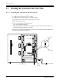
HY
BR
ID
SY
STE
M
Note
For installing the 4 CO Line Expansion Unit to the main unit, refer to 2.4.4
Expansion Unit.
Installing
Programming Guide Reference
[110] Caller ID Code Set
[111] Caller ID Name Set
[125] Area Code Assignment
[126] Caller ID Modification for Local Call
[127] Caller ID Modification for Long Distance Call
[406] Caller ID Assignment
Features Guide Reference
Caller ID
72
Installation Manual
General Installation
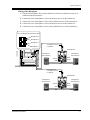
2.4.7
Doorphone and Door Opener Connection
To connect up to four doorphones (KX-T30865) and up to four door openers (user-supplied),
a Doorphone / Door Opener Interface Card (KX-TA123260) is required.
Installing the Doorphone
1. Loosen the screw to separate the doorphone into two halves.
ic
ason
Pan
screw
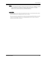
2. Install the base cover to the wall with two screws.
Note
Two kinds of screws are included. Please choose the appropriate one depending on your wall
type:
Type 1: When the doorphone
plate has been fixed to
the wall.
Type 2: When you wish to
install the doorphone
directly to the wall.
3. Connect the wires to the screws located in the front cover.
To the terminal box (See
"Wiring of the Doorphone".)
4. Secure both halves together and re-install the screw.
Installation Manual
73
General Installation
Doorphone / Door Opener Interface Card Installation
1. Connect two 4-conductor modular connectors to the Doorphone / Door Opener Interface
Card Cabinet, and pass the cords through the grooves in the cabinet.
2. Attach the Doorphone / Door Opener Interface Card Cabinet to the main unit and press
down.
3. Connect the cord to the Doorphone / Door Opener Interface Card Connector.
To Terminal Box Installation
74
Installation Manual
General Installation
Wiring of the Doorphone
1. Connect the Doorphone / Door Opener Interface Card to the terminal box using two 4conductor modular connectors.
2.
3.
4.
5.
Connect the wires of doorphone 1 to the red and green screws of the terminal box.
Connect the wires of doorphone 2 to the yellow and black screws of the terminal box.
Connect the wires of doorphone 3 to the red and green screws of the terminal box.
Connect the wires of doorphone 4 to the yellow and black screws of the terminal box.
View of Doorphone Connector Jack
Doorphone 4
Doorphone 3
Doorphone 2
Doorphone 1
4-conductor wiring
is required.
Terminal Box
Doorphone 4
(KX-T30865)
Doorphone 3
(KX-T30865)
Yellow
Red
Black
Green
Panasonic
Panasonic
4-conductor wiring
is required.
Terminal Box
Doorphone 2
(KX-T30865)
Doorphone 1
(KX-T30865)
Yellow
Red
Panasonic
Installation Manual
Black
Green
Panasonic
75
General Installation
Connecting Door Openers
1. Loosen the screw to remove the cover.
2. Loosen the screws on the terminal strip.
76
Installation Manual
General Installation
3. Insert the wires coming from the door openers into holes and tighten the screws.
Pass all the wires through the Holder.
Holder
To door opener 4
To door opener 3
To door opener 2
To door opener 1
Note
• Set the door opener paired with the doorphone.
• For wiring, UL 1015, AWG 22 twisted wire or the equivalent is recommended.
• The wire should be between 1.2 mm and 2.4 mm (3/64 inch and 3/32 inch) in diameter
including the coating.
D=1.2 mm-2.4 mm (3/64 inch-3/32 inch)
Installation Manual
77
General Installation
Maximum cabling distance of the doorphone and the door opener line
The maximum length of the doorphone and door opener line that connects to the main unit is
shown below:
A1232
ADVANCED
HYBRID SYSTE
M KX-TA1232
26 AWG: Under 70 m (230 feet)
24 AWG: Under 113 m (370 feet)
22 AWG: Under 180 m (590 feet)
Panasonic
Doorphone
KX-T30865
Panaso
nic
22 AWG: Under 180 m (590 feet)
Door Opener
Programming Guide Reference
[607-608] Doorphone Ringing Assignment —— Day / Night
Features Guide Reference
Door Opener
Doorphone Call
78
Installation Manual
General Installation
2.5
Auxiliary Connection for Power Failure Transfer
2.5.1
Auxiliary Connection for Power Failure Transfer
Power Failure Transfer connects specific single line telephones to selected outside lines in the
event of system power failure as follows:
Outside Line 1 — Extension (T, R) Jack 1 /
Outside Line 3 — Extension (T, R) Jack 9 /
Outside Line 9 — Extension (T, R) Jack 17
Connections of outside lines 1 through 3 and the respective extensions require no auxiliary
connection. Outside line 9 requires auxiliary connection to implement this feature.
Insert the modular plugs of connection cords (4-conductor wiring) to the modular jacks of 4
CO Line Expansion Unit and the amphenol connector of 8 Extension Expansion Unit 1.
8E
P
FT
po
X
rts
T
A
D
V
A
N
C
E
D
H
Y
B
R
ID
S
Y
S
TE
M
2C
O
T2 R1 T1 R2
R: Ring
T: Tip
4C
P
FT
O
P
A
R
TS
A
D
V
A
N
C
E
D
H
Y
B
R
ID
2C
O
S
Y
S
W
/P
TE
FT
M
2C
O
View of TEL Jack (Outside Line)
P
an
as
on
ic
Note
• In the event of a power failure, system memory is protected by a factory-provided lithium
battery. There is no memory loss except the memories of Camp-on, Saved Number Redial,
Last Number Redial, Call Park and Message Waiting.
• The system changes the current connection to this connection automatically when the
power supply stops.
• If DC power is available from backup batteries if AC power fails, the system does not
change the current connection to the above connection.
Features Guide Reference
Power Failure Transfer
Installation Manual
79
General Installation
2.6
Closing the Front Cover
2.6.1
Closing the Front Cover
1. Fasten all the cables and cords with the cord fastener.
2. Replace the cover and tighten the screw.
Note
Be sure to tighten two screws, or the unit may not work properly.
A1232
ADVANCED
HYBRID SYSTE
M KX-TA1232
D816
DIGITAL SUPE
R HYBRID SYSTE
M
screw
screw
Panas
onic
screw
screw
Panaso
nic
80
Installation Manual
General Installation
3. Tie together all of the connected cords and attach them to the wall so that the cords cannot
be pulled out of the main unit.
A1232
ADVANCED
HYBRID SYSTE
M KX-TA1232
D816
DIGITAL SUPE
R HYBRID SYSTE
M
Panas
onic
Installation Manual
81
General Installation
2.7
Starting the System for the First Time
2.7.1
Starting the System for the First Time
1.
2.
3.
4.
5.
Set the Power Switch to the "OFF" position.
Set the System Clear Switch to the "CLEAR" position.
Plug the AC power cord into the system and an AC outlet.
Turn the Power Switch on.
Press the Reset Button with a pointed tool.
(The power indicator will flash.)
6. Slide the System Clear Switch to the "NORMAL" position while the power indicator is
flashing (within approximately 10 seconds).
The system will be initialized with default values. The system will also check the outside lines,
extensions, and optional cards and units.
System Clear
Switch
SYSTEM
CLEAR
CLEAR
NORMAL
RESET
Reset Button
Power Indicator
82
Power
Switch
To AC Outlet
Installation Manual
General Installation
Notice
• After pressing the Reset Button, slide the System Clear Switch to the "NORMAL" position
at step 6 while the power indicator is flashing (within approximately 10 seconds).
Otherwise, the system will not start up with the default values.
CAUTION
The power supply cord is used as the main disconnect device, ensure that the socket-outlet is
located/installed near the equipment and is easily accessible.
Once you start up the system and you turn the power off, do not perform the above procedure
to start the system again. Otherwise, your programmed data will be cleared. To start the
system, just turn the Power Switch on.
Installation Manual
83
General Installation
2.8
System Restart
2.8.1
System Restart
After starting the system, if the system does not operate properly, restart the system.
Before restarting the system, try the system feature again to confirm whether there definitely
is a problem or not.
System Restart causes the following:
a) Camp-on is cleared.
b) Calls on Hold are terminated.
c) Calls on Exclusive Hold are terminated.
d) Calls in progress are terminated.
e) Call Park is cleared.
Other data is not cleared by System Restart.
1. Make sure that the System Clear Switch is set to the "NORMAL" position.
2. Press the Reset Button with a pointed tool.
Notice
After pressing the Reset Button, if you notice that the System Clear Switch is set to the
"CLEAR" position, never slide the System Clear Switch to the "NORMAL" position within 20
seconds. Otherwise, all the system programming data are reset to default values (Refer to
2.9.1 System Data Clear). Wait at least 30 seconds, then slide to the "NORMAL" position.
Then the system will work as before.
If the system still does not operate properly, please see 3.1.4 Using the Reset Button.
84
Installation Manual
General Installation
2.9
System Data Clear
2.9.1
System Data Clear
After storing or changing the system programming data, it is possible to clear your
programming data stored in the system, if required. The system will restart with the default
setting.
1. Slide the System Clear Switch to the "CLEAR" position.
2. Press the Reset Button with a pointed tool.
3. Return the System Clear Switch to the "NORMAL" position while the power indicator is
flashing (within approximately 10 seconds).
Notice
After pressing the Reset Button, return the System Clear Switch to the "NORMAL" position
in step 3 while the power indicator is flashing (within approximately 10 seconds). Otherwise,
the system will not clear.
Installation Manual
85
General Installation
86
Installation Manual
Troubleshooting
Section 3
Troubleshooting
This section provides information for system and
telephone troubleshooting.
Installation Manual
87
Troubleshooting
3.1
Troubleshooting
3.1.1
Installation
PROBLEM
Extension does not operate.
PROBABLE CAUSE
POSSIBLE SOLUTION
Bad printed circuit board
(Extension Unit).
Exchange printed circuit board for
another printed circuit board.
Bad connection between the
system and extension.
Take the extension and plug it into the
same extension port using a short
telephone cord. If the telephone does not
work, the connection between the system
and the extension must be repaired.
A telephone with an A-A1
relay is connected.
Use a 2 wire cord.
Set the A-A1 relay switch of the
telephone to the "OUT" or "OFF"
position.
Bad extension.
Take the extension and plug it into
another extension port that is working.
If the telephone does not work, replace
the phone.
Incorrect reset operation.
Press the Reset Button.
Noise in external paging.
Induced noise on the wire
between the system and the
amplifier.
Use a shielded cable as the connection
wire between the system and amplifier. A
short shielded cable is recommended.
Volume distortion from
external music source.
Excessive input level from
external music source.
Decrease the output level of the external
music source by using the volume
control on the music source.
Speed Dialing or One-Touch
Dialing does not function.
Bad programming.
Enter the outside line access number (9,
81 through 88) into programming.
88
Installation Manual
Troubleshooting
3.1.2
Connection
Connection between the system and a proprietary telephone:
Connection between the system and a proprietary telephone:
Can you dial
an extension?
No
CAUSE
The T / R is connected to the L / H.
L
T
R
H
L
T
R
H
KX-TA1232
SOLUTION
Use the correct cord (inner 2
wires are for T / R and the
outer 2 wires are for L / H).
extension
Connection between the system and a single line telephone:
CAUSE
Yes
SOLUTION
The T / R is connected to the L / H.
L
T
R
H
KX-TA1232
T
R
extension
Use the correct cord (inner 2
wires are for T / R).
• If a telephone equipped
with an A-A1 relay is
connected to the system,
set the A-A1 relay switch
of the telephone to "OFF".
Connection between the system and a single line telephone that is polaritysensitive:
CAUSE
The "T" is connected to the "R".
L
T
R
H
(Continued on the
following.)
Installation Manual
KX-TA1232
SOLUTION
Reverse the connections of
the T / R.
T
R
extension
89
Troubleshooting
Connection between the central office and the system:
Connection between the central office and the system:
(Continued from the
previous.)
Can you dial
out on an
outside line?
CAUSE
SOLUTION
Outside lines are connected to the T2 / T1. Reconnect the outside lines
to the T1 / R1 or T2 / R2 of the
T2
telephone jack using 2R1
conductor wiring.
T1
R2
No
Outside line
KX-TA1232
Outside lines are connected to the T2 / R1.
T2
R1
T1
R2
Outside line
90
KX-TA1232
Installation Manual
Troubleshooting
3.1.3
Operation
PROBLEM
PROBABLE CAUSE
POSSIBLE SOLUTION
• When using the
• The HANDSET /
speakerphone mode with a
HEADSET selector of the
proprietary telephone KXKX-T7135, KX-T7130 or
T7135, KX-T7130 or KXKX-T7030 is set to the
T7030, nothing is audible.
"HEADSET" position.
• When the headset is not used, set the
HANDSET / HEADSET selector to
the "HANDSET" position.
• The unit does not ring.
• The Ringer Volume
Selector is set to "OFF".
• Set to "HIGH" or "LOW".
• During a power failure,
extensions connected to
jack numbers 1, 9 and 17
for KX-TA1232 do not
operate.
• An analog proprietary
telephone (APT) is
connected to the jack.
• The dialing mode (tone or
pulse) is improper.
• Disconnect the APT and connect a
single line telephone.
• Set the Tone / Pulse switch to the
other position.
• Originating an outside call, • The corresponding CO
• Program the CO button. See Section
Call Transfer, or
button does not exist on the
[005] Flexible CO Button
Conference cannot be
proprietary telephone.
Assignment.
performed.
Installation Manual
91
Troubleshooting
3.1.4
Using the Reset Button
If the system does not operate properly, use the Reset Button.
Before using the Reset Button, try the system feature again to confirm whether there definitely
is a problem or not.
1. When the System Clear Switch is set to "NORMAL", pressing the Reset Button causes the
following:
a) Camp-on is cleared.
b) Calls on Hold are terminated.
c) Calls on Exclusive Hold are terminated.
d) Calls in progress are terminated.
e) Call Park is cleared.
All other data stored in memory is not cleared.
2. When the System Clear Switch is set to the "CLEAR" position, you must press the Reset
Button with caution. All data stored in memory will be cleared by the following operation:
pressing the Reset Button and setting the System Clear Switch to the "NORMAL" position
while the Power Indicator is flashing.
Operation
1. If the system does not operate properly,
a) Make sure that the System Clear Switch is set to the "NORMAL" position.
b) Press the Reset Button with a pointed tool.
2. If the system still does not operate properly,
a) Set the System Clear Switch to the "CLEAR" position.
b) Press the Reset Button with a pointed tool.
c) Return the System Clear Switch to the "NORMAL" position while the Power Indicator
is flashing (approximately within 10 seconds).
3. If the system still does not work, switch the power off and on again after five minutes.
4. If the system still does not work,
a) Switch the power off.
b) Set the System Clear Switch to the "CLEAR" position.
c) Switch the power on.
d) Press the Reset Button with a pointed tool.
e) Set the System Clear Switch to the "NORMAL" position while the Power Indicator is
flashing (approximately within 10 seconds).
92
Installation Manual
Troubleshooting
5. If the system still does not work, switch the power off. Then consult an authorized service
person.
When the power supply stops, certain extensions are automatically connected straight to
specific outside lines:
Extension (T, R) of jack number 1: Outside line 1
Extension (T, R) of jack number 9: Outside line 3
Extension (T, R) of jack number 17: Outside line 9
Connect single line telephones to the above extension jacks.
Installation Manual
93
Troubleshooting
94
Installation Manual
Index
Section 4
Index
95
Index
Numerics
K
4 CO Line Expansion Unit (KX-TA123280) 22
4 CO Line Expansion Unit Connection 60
8 Extension Expansion Unit (KX-TA123270) 22
8 Extension Expansion Unit Connection 61
KX-T30865 (Doorphone)
A
Advanced Hybrid System
16
Amphenol 57JE Type 68
Analog Proprietary Telephones (APT) 16
Auxiliary Connection for Power Failure Transfer
79
Basic System Construction
Before Installation 28
Lightning Protectors
54
Location of Interfaces 31
Location of Optional Cards and Units
57
M
Maximum Cabling Distance
Module Expansion
16
38
Opening Front Cover
34
22
Options
Outside Line Connection
37
18
C
Caller ID 17
Caller ID Card (KX-TA123293)
24
Characteristics
Closing the Front Cover 80
P
22
D
DISA Card 70
DISA Card (KX-TA123291) 22, 70
DISA Card, Doorphone / Door Opener Interface
Card
58
Doorphone 73
Doorphone (KX-T30865) 22
Doorphone / Door Opener Interface Card
74
Doorphone / Door Opener Interface Card (KXTA123260)
22
Doorphone and Door Opener Connection
73
DSS Console (KX-T7040) 22
E
Extension Connection 38
48
External Music Source Connection
External Pager (Paging Equipment) Connection
47
F
Frame Ground Connection
35
G
Installing Expansion Unit
Paralleled Telephone Connection
16, 44
Pin Number Chart
41
45
Polarity Sensitive Telephone Connection
Power Failure Transfer
79
Printer and PC Connection
50
16
Programming System
Proprietary Telephones
21
R
Remote Station Lock Control 17
Reset Button 82, 83, 84, 85, 92
S
Serial Interface (RS-232C) Signals 52
Starting the System for the First Time
82
System Capacity
25
System Clear Switch 82, 84, 85, 92
System Connection Diagram
19
System Highlights
16
16
System Maximum Capacity
T
Telephone Connection
43
Telephone Wiring
38
Trunk (Outside Line) Answer From Any Station
(TAFAS)
17
U
23
Unpacking
I
96
L
O
B
General Description
22
62
30
V
Voice Mail Integration
16
Index
W
Wall Mounting
32
97
Index
98
Index
99
Panasonic Consumer Electronics
Company, Division of Matsushita
Electric Corporation of America
Panasonic Sales Company (“PSC”),
Division of Matsushita Electric of
Puerto Rico, Inc.
One Panasonic Way, Secaucus,
New Jersey 07094
Ave. 65 de Infantería, Km. 9.5,
San Gabriel Industrial Park, Carolina,
Puerto Rico 00985
Copyright:
This manual is copyrighted by Kyushu Matsushita Electric Co., Ltd. (KME). Under the applicable
copyright laws, this manual may not be reproduced in any form, in whole or part, without the prior
written consent of KME and its licensee.
C
2001 Kyushu Matsushita Electric Co., Ltd. All Rights Reserved.
Printed in the United Kingdom
PSQX2423ZA KA0401HK0