1
1
HV1000 Series Inverter
User manual
V1.2
HNC Automation Limited
2
Version 2.1
Revision date September 3, 2013
HNC Automation provides customer with technical support.
Users may contact the nearest HNC Automation sales office or service
center.
Copyright © 2013 by HNC Automation Limited
All rights reserved. The contents in this document are subject to change
without notice.
Home Page: www.hncautomation.com
1
Contents
1.
Preface .............................................4
2.
Inspection...........................................5
3.
Safety precautions ....................................6
3.1 Safety definition ............................................. 6
3.2 Safety items ................................................. 6
3.3 Notice Items ................................................ 8
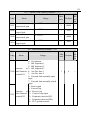
4.
Specifications and Optional Parts ....................... 12
4.1 Specifications .............................................. 12
4.2 Products Series Introduction ................................... 14
4.2.1 HV1000 Models ...................................... 14
4.2.2 Ordering information of HV1000 series .................... 15
4.2.3 Size ................................................ 16
4.2.4 Protective cover....................................... 19
4.2.5 LED Keypad Display Unit Size........................... 19
4.2.6 Optional Parts ........................................ 20
4.2.7 Braking Resistor and Recommendation of Braking Unit ....... 20
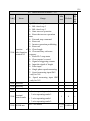
5.
Installation and wiring ............................... 23
5.1 Installation ................................................. 23
5.1.1 EMC Compliance Installation ............................ 24
5.1.2 Noise Suppression ..................................... 26
5.1.3 Using Surge Suppressor ................................ 28
5.1.4Leakage Current ....................................... 28
5.1.5 Applications of Power Filter ............................. 29
5.1.6 AC Line Reactor Applications............................ 30
5.2 Wiring .................................................... 30
5.2.1 Overview............................................ 31
5.2.2 Power Terminals ...................................... 33
5.2.3 Control Circuit Wiring.................................. 34
5.2.4 Onsite Wiring Requirements ............................. 46
5.2.5 Earthing............................................. 47
6.
Operation Procedures ................................ 49
6.1 Term Definition ............................................. 49
6.1.1 Inverter Control modes ................................. 49
6.1.2 Frequency Setting Method............................... 49
6.1.3 Inverter Operation Status................................ 49
6.1.4 Operating Mode....................................... 50
6.2 Operation Guide ............................................ 50
2
6.2.1 LED Keypad ......................................... 50
6.2.2 Keypad Function Explanation ............................ 51
6.2.3 Indicator Description................................... 52
6.2.4 Parameter Setting Method ............................... 53
6.2.5 Speed Setting......................................... 55
6.2.6 Locking/Unlocking Keypad ............................. 55
7.
Parameters.........................................57
7.1 Basic Parameters(P0) ...................................... 57
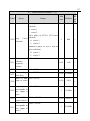
7.2 Motor Parameter(P1) ...................................... 62
7.3 Start/Brake Parameter(P2) .................................. 65
7.4 Flux vector control parameters(P3) ........................... 70
7.5 Current vector control parameter(P4).......................... 73
7.6 Multi-function terminal(P5) ................................. 74
7.7 Output terminal control parameters(P6) ........................ 86
7.8 Close-loop control(P7) ..................................... 93
7.9 MS parameters(P8)........................................ 99
7.10 Enhanced function(P9)................................... 100
7.11 Display Control Parameters(PA) ........................... 114
7.12 Communication(PB)..................................... 117
7.13 Traverse Parameters(PC) ................................. 118
7.14 PLC parameters(PD) .................................... 122
7.15 Protection(PL) ......................................... 127
7.16 Operation Time and Temperature of Cooling Fan (PN).......... 133
7.17 Protection of Parameters(PP) .............................. 134
7.18 Factory Default(PU)..................................... 135
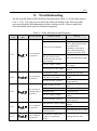
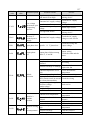
8.
Troubleshooting.................................... 136
9.
Maintenance ...................................... 142
9.1 Routine Maintenance........................................ 142
9.2 Periodic Maintenance ....................................... 143
9.3 General Inspection:: ....................................... 143
9.4 Replacing Easily-worn Parts .................................. 143
9.5 Storing Inverters ........................................... 144
9.6 Warranty ................................................. 144
Parameter Set ......................................... 146
10.
Communication Protocal ......................... 194
10.1 Communication Mode ...................................... 194
10.2 Protocol Format........................................... 194
10.3 Protocal function .......................................... 195
10.4 Application .............................................. 204
3
10.5 Scaling.................................................. 205
4
1.
Preface
Thank you for using HV1000 series inverter made by HNC Automation Limited
HV1000 series satisfies high performance requirements by using a unique
control method to achieve high torque, high accuracy and wide speed-adjusting range.
Its anti-tripping function and capabilities of adapting severe power network,
temperature, humidity, and dusty environment exceeds those of similar products made
by other companies, which improves the products reliability noticeably.
HV1000 consider customers’ needs and combines general purpose function and
industrial-oriented function. It features PI control, simple PLC, flexible I/O terminals
and pulse frequency setting. You can select whether to save the parameters upon
power off or stop, bind frequency setting channel with command channel, zero
frequency return difference zero frequency hysteresis, main and auxiliary frequency
setting, traverse operation, length control, etc. It is an integral, cost-effective and
highly reliable solution for manufacture in the related fields.
HV1000 series can satisfy the customers’ requirements on low noise and EMI by
using optimized PWM technology and EMC design.
This manual provides information on installation, wiring, parameters setting,
trouble-shooting, and routine maintenance. In order to ensure the correct installation
and operation of the inverter, please read this manual carefully before using and keep
it in a safe place.
5
2.
Inspection
Don’t install or use any inverter that is damaged or have fault parts otherwise
may cause injury.
Check the following items when unpacking the inverter.
1.
Ensure there is operation manual and warranty cards in the packing box.
2.
Inspect the entire exterior of inverter to ensure there are no scratches or
other damaged caused by transportation.
3.
Check the nameplate and ensure it is what you ordered.
4.
Ensure the optional parts are what you need if you have ordered any
optional parts.
Please contact the local agent if there is any damage in the inverter or the
optional parts.
6
3.
Safety precautions
3.1 Safety definition
In this manual, the safety precautions are sorted to “Danger” or “Caution”
! DANGER
Operations without following instructions can cause personal injury or death.
! CAUTION
Operation without following instructions can cause personal injury or damage to
product or other equipment.
3.2 Safety items
Before installation:
! DANGER
1.
Please don’t use the inverter of being scathed or loss of parts!
2.
Please use the insulating motor upwards B class; otherwise it will result in death
or serious injury on account of getting an electric shock!
When installation:
! DANGER
Please install the inverter on the fireproofing material (such as metal) to prevent fire!
! CAUTION
1.
When you need to install two or more inverters in one cabinet, cooling fans
should be provided to make sure that the ambient temperature is lower than 45
℃. Otherwise it could cause fire or damage to the device.
2.
No wires head or screws fall into the inverter!
When wiring:
! DANGER
1.
Only qualified personnel shall wire the inverter!
2.
Inverter and power must be comparted by the breaker; otherwise the fire will be
caused!
3.
Never wire the inverter unless the input AC is totally disconnected!
4.
The ground terminal must be properly earthed to reduce electrical accident!
! CAUTION
1.
Connect input terminals(R,S,T) and output terminals(U,V,W) correctly.
7
Otherwise it will cause damage the inside part of inverter!
2.
Make sure that the wring according with EMC requirements and safety
standards in the region, the wire diameter used reference the manual suggested;
otherwise it will cause an accident!
3.
Brake resistor cannot be directly connected between “DC bus+” and “DC bus-”
terminals, or it may cause a fire!
Before power-on:
! DANGER
1.
Please confirm whether the power and voltage level is consistent with the rated
voltage of the inverter, input and output wiring position is correct or not, and
pay attention to check whether there are short-circuit in the external circuit
phenomenon, ensure the line is fastened. Otherwise the inverter may cause
damadge!
2.
Install the cover before power-on, in order to reduce the danger of electric
shock!
! CAUTION
1.
Inverters do not need to do pressure test, factory products have made this test,
and otherwise it may cause an accident!
2.
All the external parts are connected exactly in accordance with this manual, or it
may cause an accident!
After power-on:
! DANGER
1.
Do not open the cover after power-on, otherwise there is a risk of electric shock!
2.
Do not wire and operate the inverter with wet hands, otherwise there is a risk of
electric shock!
3.
Do not touch inverter terminals (including the control terminals), otherwise
there is a risk of electric shock!
4.
At the beginning of power-on, the inverter can carry out safety testing for
external strong electric circuit automatically, at this time, please do not touch
U,V,W terminals or motor terminals, otherwise there is a risk of electric shock!
! CAUTION
1.
8
If you need parameter identification, please note that the risk of injuries in
motor rotation, otherwise it may cause an accident!
2.
Please do not arbitrarily change the parameters of inverter manufactures;
otherwise it may result in equipment damage!
Operating status:
! DANGER
1.
When the user selects the function re-starting, please do not stay close to the
mechanical equipment, otherwise it may cause personal injury!
2.
Do not touch the radiator, otherwise it may cause burn!
3.
Only qualified personnel shall detect the signal, otherwise it may cause personal
injury or equipment damage!
! CAUTION
1.
When the inverter is running, please avoid the sundries fall into the device,
otherwise it would cause equipment damage!
2.
Please do not use the method of contactor on and off to control the inverter’s
start-stop, otherwise it would cause equipment damage!
When maintaining:
! DANGER
1.
Never service and maintain and maintain the inverter with electrification,
otherwise it may cause injury or electric shock!
2.
Ensue the inverter’s “CHARGE” light turns off before the maintenance and
repair of the inverter, otherwise the residual charge on the capacitor may cause
personal injury!
3.
Only trained personnel shall operate and maintain this equipment, otherwise it
will cause personal injury or equipment damage!!
3.3 Notice Items
1.
Insulation of Motors
Before using the inverter, the insulation of motors must be checked, especially, if
it is used for the first time or if it has been stored for a long time. This is to
reduce the risk of the inverter from being damaged by the poor insulation of the
9
motor winding. Please use 500V insulation tester to measure the insulation
resistance. It should not be less 5MΩ.
2.
Thermal protection of the motor
If the selection of motor and rated capacity of the inverter does not match,
especially when rated power of the inverter is greater than rated power of the
motor, be sure to adjust the motor protection-related parameters in the inverter or
pre-installed in the motor thermal relay for motor protection.
3.
Working above power frequency
The inverter can provide 0Hz-60Hz output frequency, if the customers need to
run at 50Hz or above, please consider the affordability of mechanical devices.
4.
The vibration of mechanical devices
When the output frequency to achieve certain values of the inverter, you may
encounter a mechanical resonance point of the load devices. It can be avoided by
setting the parameters of the frequency jump in inverter.
5.
Regarding motor heat and noise
Because the output voltage of the inverter is the PWM wave,it contains some
harmonics wave, Therefore, there will be some increase in temperature、noise、
libration in motor and Work-frequency.
6.
Varistors for Surge Protection or Capacity Used to improve the Power Factor
Don’t connect any varistors or capacitors to the output terminals of the inverter.
Because the inverter’s output voltage waveform is pulse wave, otherwise, it may
cause tripping or damage to components。
7.
If circuit breaker or contactor needs to be connected between the inverter and
the motor, be sure to operate these circuit breakers or contactor when the
inverter has no output to avoid damaging of the inverter. Otherwise it may cause
damage to the inverter module.
8.
Using outside rated voltage
The inverter is not suitable to be used out of the specified range of operating
voltage. If needed, please use suitable voltage regulation device.
9.
Three-phase input change to Two-phase input
Don’t permit of changing three-phase inverter as two-phase to be used, or it will
result in failure or damage to inverter.
10
10.
Protection against lightning strike
There are transient surge suppressors inside the inverter that protect it against
lightning strike.
11.
Derating due to Altitude
Derating must be considered when the inverter is installed at high altitude, greater
than 1000m. This is because the cooling effect of the inverter is less effective in
the thin air. For details, please contact us。
12.
Some special usages
If the customer need to use the wiring diagram that the manual did not mention ,
such as the common DC bus ,please contact us.
13.
Disposing Unwanted inverters
1)The capacitors may explode when they are burnt.
2)Poisonous gas may be generated when the plastic parts like front covers are
burns.
14.
3)Please dispose the inverter as industrial waste.
Adaptive motor
1)Standard adaptive motor for 4 grade Squirrel-cage asynchronous induction
motor. If it is not above motor that may select the inverter according to rated current
of motor. If you need to inverter permanent magnet synchronous motor, please ask for
support。
2)The cooling fan of non-inverter motor and the rotor axis is a coaxial connection,
the effect of fan cooling is poor when the speed decreases, therefore, should be
retrofitted with exhaust fan or replace for the inverter motor in the motor overheat
occasion。
3)The inverter has built-in standard parameters of adaptive motor, according to
the actual situation ,Motor parameter identification needs to be done or personality
default value in order to be compatible with the actual value, otherwise it will affect
the running results and protection performance.
4)If the short-circuit occurred in the cable or the internal motor will cause the
inverter alarm, and even deep-fried machine. When the motor and cable just installed,
please first conduct insulation short-circuit tests, routine maintenance is also required
11
to conduct this test regularly。
Before using, please read this manual thoroughly to ensure proper usage. Keep
this manual at an easily accessible place so that can refer anytime as necessary.。
12
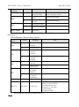
4.
Specifications and Optional Parts
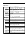
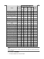
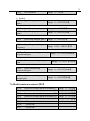
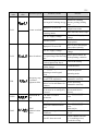
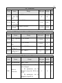
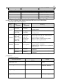
4.1 Specifications
Table2-1 HV1000 Specifications
Item
Description
Rated voltage; HV1000-4T-xxxxx:380V~440V;50Hz/60Hz
Frequency
HV1000-2Sxxxxx:200V~240V;50Hz/60Hz
Inpu
Continuous fluctuation range≤±10%,Short time
Permissible
t
fluctuation
fluctuation range≤-15%~+10%;
range
Voltage unbalance range≤3%;Frequency≤5%
HV1000-4T-xxxxx:0~380V/440V
Rated voltage
HV1000-2Sxxxxx:0~200V/240V
Frequency
0Hz~650Hz
Outp
G type:150%rated current for 1 minute,180%rated
ut
current for 3s/1s(380V/220V series),200% rated current
Over load ability
for 0.5s;
P type:120% rated current for 1 minute
Cont Modulation
Flux vector PWM modulation
rol mode
func Speed range
1:100
tions Starting torque 180% rated torque at 0.5Hz
Accuracy of
speed at steady ≤±0.5% rated synchronous speed
state
Torque boost
Auto torque boost,Manual torque boost
Linear、S curve;4 Acc/Dec time;
Acc/Dec curve
Unit(minute/second),60hours at most
Jog frequency: 0.10-60.00Hz: Acc/Dec time: 0.1-60.0s.
Jog
Jog interval adjustable
Multi-speed
Seven sections of frequency. Able to achieve through the
operation
built-in PLC or terminals.
Closed-loop
Analog closed-loop,speed closed-loop control
control
Auto energy
Voltage output is optimized automatically according to the
saving operation load condition to perform energy-saving operation.
Auto voltage
Constant output voltage even if electric network voltage
regulation
fluctuates
Auto current
Operating current is limited automatically to avoid
limiting
frequent tripping of the inverter
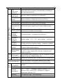
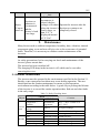
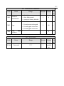
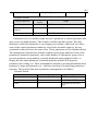
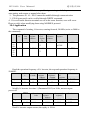
13
Item
Auto
carrier-wave
regulation
Traverse for
textile motor
Set length
control
Droop control
Tone selection
Immunity to
transient power
Cust failure
omiz
Channel binding
ed
and Methods of
oper inputting
ating commands
func Methods of
tions setting up
frequency
Auxiliary
frequency
Pulse output
terminal
Analog output
terminals
Cont
LED keypad
rol
pane
Keypad lock
l
Protection function
Envi Operating
ron environment
ment Altitude
Ambient
temperature
Humidity
Vibration
Description
Adjust the carrier frequency automatically according to
the load characteristics;
Traverse control, central traverse adjustable
When reaching set length, the inverter will stop
When many inverters control single load
Set the tone of the motor when it is running
The inverter gives output even if power failure occurs
Command channel can bind with frequency. Setting
channel and switched synchonizingly
Via keypad panel、terminals and serial port
Digital setting、VCI、CCI、pulse setting、serial port
Flexible auxiliary frequency tuning、frequency synthesis
0~50kHz pulse signal output . Signals can be reference
frequency and output frequency
2 analog outputs of 0/4~20mA and 0~10V(selectable).
Be able to output signals like reference frequency and
output frequency.
Able to show many parameters, such as: frequency setting,
output frequency, output voltage, etc.
Total lock or partially lock, in order to avoid misoperation
Phase loss failure, Over/Under current, Over/Under
voltage protection, Overheat and overload protection
In-door,
Less than 1000m
-10℃~+40℃,derating is required from 40~50℃;
Increase every 1 above 40℃, derating 2%, highest
temperature allowed: 50℃
Less than 95% RH,no condensing
Less than5.9m/s2(0.6g)
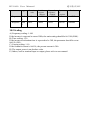
14
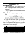
Item
Description
Storage
-40℃~+70℃
temperature
Encl Protection level IP20
osur
Cooling
Fan cooling
e
Mounting mode
Mounted in a cabinet
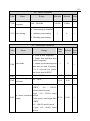
4.2 Products Series Introduction
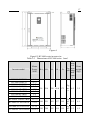
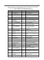
4.2.1 HV1000 Models
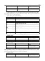
Table2-2 Inverter series
Rated
Rated
Rated input
Inverter model(G:Constant;
capacity
output
current(A)
P:Pump, fan load)
(kVA)
current(A)
HV1000-2S0R4G
1.0
5.3
2.5
HV1000-2S0R7G
1.5
8.2
4.0
HV1000-2S1R5G
3.0
14.0
7.5
HV1000-2S2R2G
4.0
23.0
10.0
HV1000-4T-0R7G
1.5
3.4
2.3
HV1000-4T-1R5G
3.0
5.0
3.7
HV1000-4T-2R2G
4.0
5.8
5.0
HV1000-4T-004G
6.3
10.0
9.0
HV1000-4T-5R5G/7R5P
8.5/11.0
15.5/20.5 13.0/17.0
HV1000-4T-7R5G/011P
11.0/17.0
20.5/26.0 17.0/25.0
HV1000-4T-011G/015P
17.0/21.0
26.0/35.0 25.0/32.0
HV1000-4T-015G/0185P
21.0/24.0
35.0/38.5 32.0/37.0
HV1000-4T-0185G/022P
24.0/30.0
38.5/46.5 37.0/45.0
HV1000-4T-022G/030P
30.0/40.0
46.5/62.0 45.0/60.0
HV1000-4T-030G/037P
40.0/50.0
62.0/76.0 60.0/75.0
HV1000-4T-037G/045P
50.0/60.0
76.0/92.0 75.0/90.0
HV1000-4T-045G/055P
60.0/72.0 92.0/113.0 90.0/110.0
HV1000-4T-055G/075P
72.0/100.0 113.0/157.0 110.0/152.0
HV1000-4T-075G/090P
100.0/116.0 157.0/180.0 152.0/176.0
HV1000-4T-090G/110P
116.0/138.0 180.0/214.0 176.0/210.0
HV1000-4T-110G/132P
138.0/167.0 214.0/256.0 210.0/253.0
HV1000-4T-132G/160P
171.0/201.0 265.0/310.0 260.0/305.0
HV1000-4T-160G/185P
201.0/250.0 310.0/385.0 305.0/380.0
HV1000-4T-200G/220P
250.0/280.0 385.0/430.0 380.0/425.0
HV1000-4T-220G/250P
280.0/316.0 430.0/485.0 425.0/480.0
HV1000-4T-250G/280P
316.0/349.0 485.0/545.0 480.0/530.0
HV1000-4T-280G/315P
349.0/395.0 545.0/610.0 530.0/600.0
HV1000-4T-315G/350P
395.0/428.0 610.0/625.0 600.0/650.0
Moto
power
(kW)
0.4
0.75
1.5
2.2
0.75
1.5
2.2
4
5.5/7.5
7.5/11
11/15
15/18.5
18.5/22
22/30
30/37
37/45
45/55
55/75
75/90
90/110
110/132
132/160
160/185
200/220
220/250
250/280
280/315
315/350
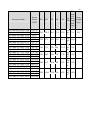
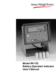
15
Rated
Inverter model(G:Constant;
capacity
P:Pump, fan load)
(kVA)
HV1000-4T-350G/400P
428.0/474.0
HV1000-4T-400G/450P
474.0/510.0
HV1000-4T-450G/500P
510.0/586.0
HV1000-4T-500G/560P
586.0/566.0
Rated
Rated input
output
current(A)
current(A)
625.0/715.0 650.0/720.0
715.0/775.0 720.0/755.0
775.0/890.0 755.0/860.0
890.0/950.0 860.0/920.0
Moto
power
(kW)
350/400
400/450
450/500
500/560
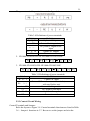
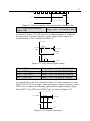
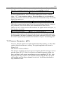
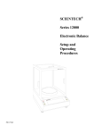
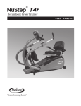
4.2.2 Ordering information of HV1000 series
Please refer to Figure2-1a and Figure 2-1b。
Table2-1a Explanations of inverter models
Model
Motor power
Rated input voltage、current、Freq.
Rated output capacity
current、voltage and freq.
Bar code
MODEL : HV 1000-4 T 5R5 G /7R5 P
POWER : 5 .5 kW /7.5 kW
INPUT: 3 PH AC 380-440 V 15 .5 A /20 .5 A 50 /60 HZ
OUTPUT: 3 PH AC 0 - 440 V 13 A /17 .0 A 0~ 650HZ
S/ N :
HNC Automation Limited
WARNING
* Risk of electric shock
* Wait 10 mins power down before removing cover
* Read the manual and follow the safety instructiongs
before use
Table2-1b HV1000 series nameplate
16
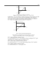
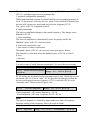
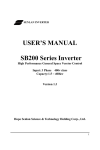
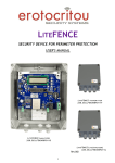
4.2.3 Size
Please refer to Figure 2-2 and Table 2-3.
Figure a
Figure b
Figure c
17
Figure d
Figure2-2 HV1000 series inverter size
Table 2-3 Dimensions of HV1000 series(mm)
Inverter model
HV1000-2S0R4G
HV1000-2S0R7G
HV1000-2S1R5G
HV1000-2S2R2G
HV1000-4T-0R7G
HV1000-4T-1R5G
HV1000-4T-2R2G
HV1000-4T-004G
HV1000-4T-5R5G/7R5P
Motor
Power W1
(kW)
0.4
0.75
1.5
2.2
0.75
1.5
2.2
4.0
5.5/7.5
HV1000-4T-7R5G/011P
7.5/11
HV1000-4T-011G/015P
11/15
HV1000-4T-015G/0185P 15/18.5
H1
H
W
D
56
216
226 69.4
171
146
251
262 157
181
180
288
305 198
181
Dia
mete
r of
Gross
Fig mou
weight
ures nting
(kg)
hole
(mm
)
Fig
ure 4.5
a
Fig
ure 5.5
b
Fig
ure 5.5
c
2.2
4.1
8.5
Inverter model
HV1000-4T-0185G/ 022P
HV1000-4T-022G/ 030P
HV1000-4T-030G/ 037P
HV1000-4T-037G/045P
HV1000-4T-045G/055P
HV1000-4T-055G/075P
HV1000-4T-075G/090P
HV1000-4T-090G/110P
HV1000-4T-110G/132P
HV1000-4T-132G/160P
HV1000-4T-160G/185P
HV1000-4T-200G/220P
HV1000-4T-220G/250P
HV1000-4T-250G/280P
HV1000-4T-280G/315P
HV1000-4T-315G/350P
HV1000-4T-35G/400P
HV1000-4T-400G/450P
HV1000-4T-450G/500P
HV1000-4T-500G/560P
Motor
Power W1
(kW)
18.5/22
22/30
30/37
37/45
45/55
55/75
75/90
90/110
110/132
132/160
160/185
200/220
220/250
250/280
280/315
315/350
350/400
400/450
450/500
500/560
H1
H
W
230 424.5 438 276
18
Dia
mete
r of
Gross
Fig mou
weight
D
ures nting
(kg)
hole
(mm
)
Fig
220 ure 7.0 10.5
c
Fig
10.0
ure
320
571
589 395 231.5
320
731
759 489
320
863
889 539
560
975 1010 704
355
Fig
ure 12.0
d
-
520 1300 1358 810
425
Fig
ure 14.0
d
-
Fig
271.5 ure 12.0
d
Fig
370 ure 12.0
d
-
-
-
19
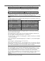
4.2.4 Protective cover
Protective cover
Input terminals
Panel
Nameplate
Notice:For ventilation, try not to use protective cover, unless there is a need,
so that you can extend the inverter’s life. HV1000-4T-004G cannot use
protective covers.
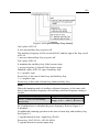
4.2.5 LED Keypad Display Unit Size
Through it, operation and configuration of the inverter can be done. Please
refer to its size and configuration in Figure 2-3.
20
Keypad dimensions of HV1000-2S0004G~4T-004G
Keypad dimensions of HV1000-4T-0055G/0075P~4T-500G/560P
Figure2-3 Keypad display unit
4.2.6 Optional Parts
You may order the optional parts below from our company.
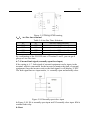
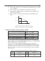
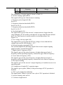
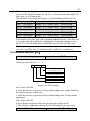
4.2.7 Braking Resistor and Recommendation of Braking Unit
HV1000 series inverter is equipped with braking unit. If there is a need for
energy-consuming braking, please select a braking resistor in Table2-4; please
refer the wiring of braking resistor and the inverter to Figure2-4. The wire
specifications are listed in Table2-4.
21
R
S
U
V
M
W
T
PE
PB (+)
Braking unit
Braking unit
……
Figure2-4 Wiring the inverter with braking resistor
Table2-4 Braking Resistor and Recommendation of Braking Unit
Suggested
Suggested
Suggested
Model
value of
model of
Remark
power
resistance
braking unit
HV1000-2S0004G
200-300Ω
50W
HV1000-2S0007G
150-250Ω
80W
HV1000-2S0015G
100-150Ω
100W
HV1000-2S0022G
80-100Ω
200W
HV1000-4T-0007G
250-350Ω
100W
HV1000-4T-0015G
200-300Ω
200W
HV1000-4T-0022G
150-250Ω
250W
Built-in
No special
HV1000-4T-004G
100-150Ω
300W
standard parts
instructions
HV1000-4T-0055G/
80-100Ω
500W
0075P
HV1000-4T-0075G/
700W
60-80Ω
011P
HV1000-4T-011G/ 015P 40-50Ω
1KW
HV1000-4T-015G/
1.5KW
30-40Ω
0185P
HV1000-4T-0185G/
25-30Ω
2KW
022P
HV1000-4T-022G/ 030P 20-25Ω
2.5KW
Add “B” at the
Built-in
HV1000-4T-030G/ 037P 15-20Ω
3KW
optional parts
end of model
HV1000-4T-037G/045P 15-20Ω
3.5KW
HV1000-4T-045G/055P 10-15Ω
4.5KW
HV1000-4T-055G/075P 10-15Ω
5.5KW
HV1000-4T-075G/090P 8-10Ω
7.5KW
No special
BU4R150
HV1000-4T-090G/110P 8-10Ω
9KW
instructions
HV1000-4T-110G/132P
6-8Ω
11KW
HV1000-4T-132G/160P
6-8Ω
13.2KW
BU4R250
No special
22
Suggested
Suggested
Suggested
Model
value of
model of
Remark
power
resistance
braking unit
HV1000-4T-160G/185P
4-6Ω
16KW
instructions
HV1000-4T-200G/220P
4-6Ω
20KW
HV1000-4T-220G/250P 6-8Ω*2
11KW*2
HV1000-4T-250G/280P 6-8Ω*2 12.5KW*2
No special
BU4R250*2
instructions
HV1000-4T-280G/315P 4-6Ω*2
14KW*2
HV1000-4T-315G/350P 4-6Ω*2
16KW*2
HV1000-4T-35G/400P 4-6Ω*3
11KW*3
HV1000-4T-400G/450P 4-6Ω*3
14KW*3
No special
BU4R250*3
instructions
HV1000-4T-450G/500P 4-6Ω*3
16KW*3
HV1000-4T-500G/560P 4-6Ω*3
18KW*3
Note:*2、*3 refer to 2 or 3 resistances paralleling mode
23
5.
Installation and wiring
5.1 Installation
Please mount the inverter vertically indoors, with good ventilative conditions.
When selecting mounting environment, the followings should be taken into
account:
Ambient temperature should be within the range of-10 ℃ ~ 40 ℃. If the
temperature is higher than 40 ℃, the inverter should be derated and forced heat
dissipation is required.
Humidity should be lower than 95%,non-condensing;
Mount in the location where vibration is less than5.9m/s2(0.6g)
;
Mount in the location free of direct sunlight, dust, metal powder, corrosive gas
or combustible gas;
If there are any special requirements for installation, please contact us for
clarifications。
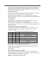
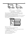
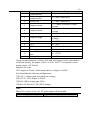
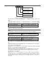
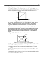
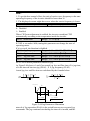
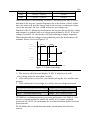
The requirements on mounting space and clearance are shown in figure 3-1 and
3-2;When two inverters are mounted one on top the other, an air flow diverting
plate should be fixed in between as shown in figure 3-3。
air expulsion by fan
100 mm or above
50 mm or above
50mm or above
100 mm or above
Figure 3-1 Installation clearance
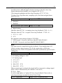
24
Inverter ...Inverter
Electric
cabinet
Figure3-2 Installation of several inverters Figure3-3 Installation of one on top the
other
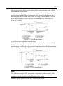
5.1.1 EMC Compliance Installation
In a traction system composed of a inverter and a motor,if the inverter,
controllers and transduser are installed in one cabinet, the disturbance they
generate should be depressed at the connection points, therefore, a noise filter
and inrush reactor should be installed in the cabinet, so that EMC requirement
is met inside it.
The inverter is usually installed in a metal cabinet, the instruments outside the
metal cabinet is shielded and may be disturbed lightly. The cables are the main
EMI source, if you connect the cables in according to the manual, the EMI can
be suppressed effectively.
In system design phase, to reduce EMI, insulating the noise source and use the
noise subber are the best choice, but the choice is considerable. If there are a
few sensitive devices on site, just install the power line filter beside them is
enough note that the inverter and the contactor are noise source, and the
automatic devices encoder and conductor are sensible to them.。
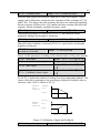
Divide the system into several EMC parts; refer to figure 3-4.
Note:
1.After installing EMI filter and AC reactor, the inverter can satisfy IEC
61800—3 standard.
2.The input/output filter should be installed close to the inverter as possible.
25
Figure3-4 Recommended System Layout:
AreaⅠ:Should be used to install transformers for control power supply,
control system and sensor.
AreaⅡ:should be used for interface of signal and control cables with good
immunity level。
AreaⅢ:Should be used to install noise generating devices such as input
reactor, inverter, brake unit and contactor.
AreaⅣ:should be used to install output noise filter.
AreaⅤ:should be used to install power source and cables connecting the RFI
filter。
AreaⅥ:should be used to install the motor and motor cables。
Areas should be isolated in space, so that electro-magnetic decoupling effect
can be achieved. The shortest distance between areas should be 20cm.
Earthing bars should be used for decoupling among areas; the cables from
different area should be placed in different tubes.
The filter should be installed at the interfaces between different areas if
necessary. Bus cable (such as RS485) and signal cable must be shielded.
26
10kV
Power
trasformer÷
Isolation
transformer÷
Power source
cable of inverter
>20cm
Power source
cable of meters
Filter
Circuit breaker
Metal cabinet
PLC
or
meters
>30cm
AC input reactor
Metal
cabinet
Inverter
Control cables
Motor cable
>50cm
AC output
reactor
Motor
Figure 3-5 Installation of the inverter
5.1.2 Noise Suppression
The noise generated by the inverter may disturb the equipment nearby; the
degree of disturbance is depend on the inverter system, immunity of the
equipment, wire connections, installation clearance and earthing methods.
27
Table3-1 Actions to reduce the noise
Noise emission paths
If the external equipment
shares the same AC
supply with the inverter, the
inverter’s noise may be
transmitted along its input
power supply cables, which
may cause nuisance tripping to
other external equipment.。
Actions to reduce the noise
Install noise filter at the input side of the inverter,
and use an isolation transformer or line filter
to prevent the noise from disturbing the external
equipment
1) The equipment and the signal cables should be
as far away as possible from the inverter.
The signal cables should be shielded and the
shielding layer should be grounded. The signal
cables should be placed inside a metal tube and
should be located as far away as possible from the
input/output cables of the inverter. If the signal
cables must cross over the power cables, they
If the signal cables of
should be placed at right angle to one another.
measuring meters, radio
2) Install radio noise filter and linear noise filter
equipment and sensors are
installed in a cabinet together (ferrite common-mode choke) at the input and
output sides of the inverter to suppress the
with the inverter, these
emission noise of power lines.
equipment cables will be
3) Motor cables should be placed in a tube thicker
easily disturbed.
than 2mm or buried in a cement conduit. Power
cables should be placed inside a metal tube and be
grounded by shielding
layer (Motor cable should be a 4-core cable, where
one core should be connected to the
PE of the inverter and another should be connected
to the motor’s enclosure)
Avoid this kind of routing. Other equipment
sensible to EMI should also be located as far away
If the signal cables are routed as possible from the inverter. The signal cables
should be placed inside a metal tube and should be
in parallel with
the power cables or bundle
placed as far away as possible from the
these cables together, the
input/output cables of the inverter.
The signal cables and power cables should be
induced electro-magnetic
noise and induced ESD noise shielded cables. EMC interference will be further
may disturb the signal cables. reduced if they could be placed inside metal tubes.
The clearance between the metal tubes should be at
least 20cm.
28
5.1.3 Using Surge Suppressor
The device such as relay, contactor and electro-magnetic braking kit, which
may generate great noises, should be installed with surge suppressor even if
installed outside of the device cabinet.
Varistor
24V DC
Diode
Inverter÷
220V AC
RC filter
220V AC
Figure3-6 Installation of Relay, contactor and electro-magnetic braking kit
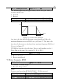
5.1.4Leakage Current
Leakage current may flow through the inverter’s input and output capacitors
and the motor’s capacitor. The leakage current value is dependent on the
distributed capacitance and carrier wave frequency. The leakage current
includes ground leakage current and the leakage current between lines 。
Ground leakage current
The ground leakage current not only flows into the inverter’s system, but also
into other equipment via earthing cables. It may cause leakage current circuit
breaker and relays to be falsely activated. The higher the inverter’s carrier
wave frequency, the higher the leakage current, and also, the longer the
motor’s cable, the greater is the leakage current.
Suppressing methods:
Reduce the carrier wave frequency, but the motor noise may be higher;
Motor cables should be as short as possible;
The inverter and other equipment should use leakage current circuit breaker
designed for protecting the products against high-order harmonic/surge
leakage current 。
Leakage current between lines
29
The line leakage current flowing outside though the distributed capacitor of
the inverter may false trigger the thermal relay, especially for the inverter of
which power rating is less than 7.5KW. If the cable is longer than 50m, the
ratio of leakage current to motor rated current may increase to a level that can
cause external thermal relay to trigger unexpectedly.
Suppression methods:
Reduce the carrier wave frequency, but the motor audible noise is higher;
Install reactor at the output side of the inverter.
In order to protect the motor reliably, it is recommended to use a temperature
sensor to detect the motor’s temperature, and use the inverter’s over-load
protection device (electronic thermal relay) instead of an external thermal
relay.
5.1.5 Applications of Power Filter
Power source filter should be used in the equipment that may generate strong
EMI or the equipment that is sensitive to EMI. The power source filter should
be a low pass filter through which only 50Hz current can flow and high
frequency current is rejected.
The power filter ensures the equipment can satisfy the conducting emission
and conducting sensitivity in EMC standard. It can also suppress the radiated
emission of the equipment
It can prevent the EMI generated by the equipment from entering power cable,
and also prevent the EMI generated by the power cable from entering the
equipment.
Common mistakes in using power line filter
Power cable is too long
The filter inside the cabinet should be located near to the input power source.
The length of the cables should be as short as possible.
The input and output cables of the AC supply filter are too close
The distance between input and output cables of the filter should be as far
apart as possible, otherwise the high frequency noise may be coupled between
the cables and bypass the filter. Thus, the filtering effect becomes ineffective.
Bad earthing of filter.
The filter enclose must be must be connected properly to the metal casing of
the inverter. In order to be earthed well, a special earthing terminal on the
filter’s enclosure should be used. If you use one cable to connect the filter to
the case, the earthing is useless due to high frequency interference. When the
frequency is high, so too is the impedance of cable, hence there is little bypass
effect.
30
The filter should be mounted in the enclosure of equipment. Ensure to clear
away the insulation paint between the filter case and the enclosure for good
earth contact.
5.1.6 AC Line Reactor Applications
Input AC Line Reactor:
A line reactor should be used if the distortion of power network is severe or
the input current harmonic level is high even after a DC reactor has been
connected to the inverter. It can also be used to improve the AC input power
factor of the inverter.
Output AC Line Reactor:
When the cables from the inverter to motor are longer than 80m, multi-strand
cables and an AC line reactor should be used to suppress the high frequency
harmonics. Thus, the motor insulation is protected. At the same time, leakage
current and unexpected trigger are reduced.
5.2 Wiring
! DANGER
·Wiring can only be done after the Variable Speed Inverter’s AC power is
disconnected; all the LEDs on the operation panel are off and after waiting for
at least 10 minutes. Then, you can remove the panel.
·Wiring job can only be done after confirming the Charge indicator inside the
inverter has extinguished and the voltage between main circuit power terminals
+ and - is below DC36V.
·Wire connections can only be done by trained and authorize personnel.
·For the sake of safety, the inverter and motor must be earthed because there is
leakage current inside the inverter; Check the wiring carefully before
connecting emergency stopping or safety circuits。
·Check the Variable Speed Inverter’s voltage level before supplying power to
it; otherwise human injuring or equipment damage may happen.
! CAUTION
·Check whether the inverter’s rated input voltage is in compliant with the AC
supply voltage before using.
·Dielectric strength test of the inverter has been done in factory and the user
needs not do it again
·Refer to chapter 2 on how to connect braking resistor or braking。
·It is prohibited to connect the AC supply cables to the inverter’s terminals U,
V and W.
·Grounding cables should be copper cables with cross-sectional area bigger
2
than 2.5 mm , and the grounding resistance should be less than 10Ω.
·For the sake of safety, the inverter and motor must be earthed because there is
leakage current inside the inverter。
31
! CAUTION
·The control circuits of HV1000 are isolated from the power circuits in the
inverter by basic insulation (single insulation) only. If the control cables are to
connect to external control circuit exposing to human contact, an extra
insulating layer, rated for use at the AC supply voltage of the load, must be
applied.
·If the control circuits are to connect to other circuits classified as Safety Extra
Low Voltage (SELV), e.g. connecting the RS485 port of the inverter to a
personal computer through an adapter, an additional isolating barrier must be
included in order to maintain the SELV classification.
! CAUTION
·The control terminals of the inverter are of ELV (Extra Low Voltage) circuit.
Do not touch them once energized;
·If the external device has touchable terminals of SELV (Safety Extra Low
Voltage) circuit. Remember to connect isolating protections in between.
Otherwise, the SELV circuit will be degraded to ELV circuit;;
·When connecting the inverter with PC, do choose RS485/232adapterswith
isolating protections that measure up to safety
requirements.。
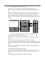
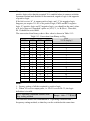
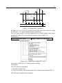
5.2.1 Overview
You should finish the power circuit and control circuit wiring。
First, open the front door,and then you will see the power terminals and
control terminals
For different models of the inverter, the power terminals layout is different,
which is described in details as below.
(Jumpers:CN is for inverters 4.0KW and below,SW is for inverters
5.5kw~110kw)
Beneath the keypad display unit, there are control terminal strip and jumpers
CN4(SW2),CN5(SW3),CN7(SW1),CN14(SW4)。
Terminal strip is relay output, analog, digital I/O and communication
interfaces. CN4(SW2),
CN5(SW3) and CN7(SW1) are jumpers through which
the output of voltage or current signal is set,the terminals will be described in
details later.
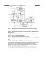
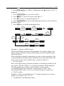
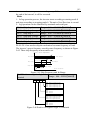
The figure below is the systematic wiring of the inverter
32
Figure 3-7 Systematic Wiring Diagram
Note:
1.In the above figure, “O” is the terminal in power circuit, and “⊙” is the
control terminal;
2.Terminal CCI can input voltage or current signal by switching the jumper
CN10 on control board;
3.Built-in braking kit is installed and a braking resistor is required to be
connected between P (+) and PB;
4.Refer to section 3.2.3 for the using of control terminals;
5.MCCB must be installed at the input side of each inverter in the cabinet;
6.Refer the cable section area and MCCB capacity to Table 3-2.
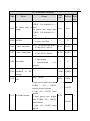
Table 3-2 Recommended MCCB Capacity and Copper Cable Section Area
Power circuit(mm2)
MCCB
Control
Circuit Inpu
cable
Model
Braking
Output
Earth
t
breaker
2
(mm
)
line
cable cable
(A) cabl
e
HV1000-2S0004G
16
1.5
1.0
1.0
2.5
1
HV1000-2S0007G
20
2.5
1.0
1.0
2.5
1
HV1000-2S0015G
32
4
1.5
2.5
4
1
HV1000-2S0022G
50
6
1.5
2.5
6
1
33
Model
HV1000-4T-0007G
HV1000-4T-0015G
HV1000-4T-0022G
HV1000-4T-004G
HV1000-4T-0055G/0075
P
HV1000-4T-0075G/011P
HV1000-4T-011G/015P
HV1000-4T-015G/0185P
HV1000-4T-0185G/
022P
HV1000-4T-022G/ 030P
HV1000-4T-030G/ 037P
HV1000-4T-037G/045P
HV1000-4T-045G/055P
HV1000-4T-055G/075P
HV1000-4T-075G/090P
HV1000-4T-090G/110P
HV1000-4T-110G/132P
HV1000-4T-132G/160P
HV1000-4T-160G/185P
HV1000-4T-200G/220P
HV1000-4T-220G/250P
HV1000-4T-250G/280P
HV1000-4T-280G/315P
HV1000-4T-315G/350P
HV1000-4T-350G/400P
HV1000-4T-400G/450P
HV1000-4T-450G/500P
HV1000-4T-500G/560P
MCCB
Circuit
breaker
(A)
10
16
16
25
Power circuit(mm2)
Control
Inpu
t Braking Output Earth cable
2
cabl
line
cable cable (mm )
e
1.0
1.0
1.0
2.5
1
1.5
1.0
1.5
2.5
1
1.5
1.5
1.5
2.5
1
2.5
1.5
2.5
2.5
1
32
4
2.5
4
4
1
32
40
63
4
6
6
2.5
4
4
4
6
6
4
6
6
1
1
1
63
10
10
10
10
1
80
100
160
200
200
250
310
400
16
25
25
35
35
70
70
95
16
25
10
16
25
70
70
95
16
25
25
35
35
70
70
95
16
16
16
16
25
35
35
50
1
1
1
1
1
1
1
1
1
1
1
1
1
1
1
1
1
1
1
Note:
If the control circuit uses multi-strand cable, the single-core cable section area
can be 0.5mm2.
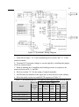
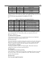
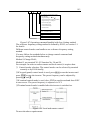
5.2.2 Power Terminals
1.HV1000-2S0004G~HV1000-4T-004G
34
The power terminal layout is shown in the figure below:
Table 3-4 Definitions of power terminals
Mark
Definition
R、S、T
3-phase AC input
+、PB
External braking resistor
DC positive, negative bus
+、—
input
U、V、W
3-phase AC outputs
PE
Protective earth
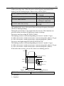
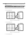
2.HV1000-4T-0055G/0075P~HV1000-4T-015G/0185P
3.HV1000-4T-0185G/022P~HV1000-4T-500G/560P
Mark
R、S、T
P1、(+)
(+)、PB
(-)
U、V、W
PE
Table 3-5 Definitions of power terminals
Definition
3-phase AC input
External DC reactor reserved terminals (connect
with steel before use)
External braking resistor
DC negative bus input
3-phase AC outputs
Protective earth
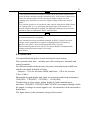
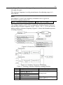
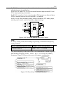
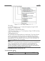
5.2.3 Control Circuit Wiring
Control Terminals and Jumpers
Refer the layout to Figure 3-8. Control terminals functions are listed in Table
3-6,Jumper’s functions in 3-7. Be sure to set the jumper and wire the
35
terminals properly. It is recommended to use cable of section area bigger than
1mm2.
HV1000-2S0015G~HV1000-4T-004G
HV1000-4T-500G/560P
HV1000-4T-0055G/0075P~
Figure 3-8 Layouts of control terminals and jumpers
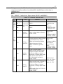
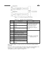
Table 3-6 Function of control terminals
Mark
Function
CN6- CN11 Analog I/O, digital I/O, relay outputs
Mark
Table 3-7 Jumpers’ function
Function&Setting
Default
CCI current/voltage input selection
CN7 I:0~20mA current signal
(SW1)
V:0~10V voltage signal
0~10V
CN14 485 terminal resistor selection:ON: 120Ω terminal No
(SW4) resistor,OFF: No terminal resistor.
resistor
CN4 AO1 current/voltage input selection
0/4~20mA: AO1 current signal 0/2~10V:
(SW2) AO1 voltage signal
0~10V
CN5 AO2 current/voltage input selection
0/4~20mA: AO2 current signal 0/2~10V: AO2 voltage
(SW3) signal
0~10V
36
Jumper usage
CN4(SW2)、CN7(SW1) or CN5(SW3) jumper usage:
Figure a means that 0~10V analog voltage input is selected;Figure b means
that 0/4~20mA analog current input is selected.
CN14(SW4) jumper usage:
Figure a means that there is a resistor(OFF)
;Figure b means that there is no resistor
(ON).
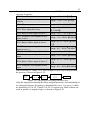
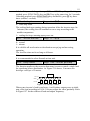
Terminal strip layout
The layout is shown below
HV1000-42S0004G~HV1000-4T-004G terminal strip layout:
TC
TB
TA
COM
PLC
Y1
Y2
P24
REV FWD COM GND VCI
COM
X1
X2
X3
X4
CCI
X5
AO1
+10V
AO2
GND
485+
485-
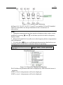
HV1000-4T-0055G/0075P~HV1000-4T-500G/560P terminal strip layout:
485+
485+10V
GND
VCI
CCI
AO1
GND
AO2
P24
X1
PLC
X2
COM
X3
FWD
X4
X5
REV
COM
Y1
1TA
Y2
1TB
2TA
1TC
2TB
2TC
TA-TB:Normally closed;TA-TC:Normally open
Contact capacity:250Vac/2A(COSφ=1)
,250Vac/1A(COSφ=0.4)
,30Vdc
/1A
TA, TB and TC can be defined as multi-functional digital output signals.
Please refer to Section 5.7
Relay output TA、TB、TC Wiring:
If there are inductive loads, such as: electro-magnetic relay and contactor,
surge snubber circuit, e.g. RC circuit, varistor, fly-wheel diode (pay attention
to the polarity when used in a DC circuit), should be installed. Note that the
37
leakage current should be less than the current in the contactor or relay. The
components in the snubber circuit should be installed near to the relay or
contactor coil.
Note:
The “+RS485-” in the above figure means RS485+ and RS485-.
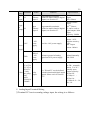
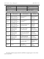
Table 3-8 Terminal function table
Cate
Terminals
gory
Com 485+
muni
catio
485n
Name
Function
Standard RS-485
communication
port,
please use
twisted-pair cable
or shielded cable
Input voltage
range:0~10V
Analog voltage input (reference
(input
ground: GND)
resistance:100kΩ)
resolution:1/2000
Input voltage
Accepting analog voltage/current range:0~10V
(input
input.CN7(SW1) can select
voltage or current input mode, resistance:100kΩ)
Input current
Voltage input mode is the
range:0~20mA
default(Reference ground:
(input
GND)
resistance:500Ω)
resolution:1/2000
Be able to output analog
voltage/current, (total 12 kinds
of signal). Jumper CN4(SW2)
can select voltage or current
input mode. Voltage input mode
is the default mode. Refer to
P6.03 for details (reference
Output current
ground: GND)
range: 0/4~20mA
Be able to output analog
Output voltage
voltage/current (total 12 kinds of range: 0/2~10V
signals). Jumper CN5(SW3)
can select voltage or current
input mode, Voltage input mode
is the
default mode. Refer to F6.04 for
details.(reference
ground: GND)
RS485+
RS485com
munication
port
RS485-
VCI
Analog
input VCI
CCI
Analog
input CCI
AO1
Analog
output 1
AO2
Analog
output 2
Anal
og
input
Anal
og
outpu
t
Specification
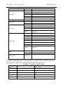
38
Cate
Terminals
gory
X1~X3
X4~X5
Name
Function
Can be defined as
multi-functional digital inputs,
see Section 5.7
Reference ground: COM
Optical-isolator
2-way input
input resistance:
2kΩ
maximum input
frequency: 200Hz
Input voltage
range: 9~30V
Multi-funct
ional
digital
inputs 4~5
Having the same function as
X1~X3, besides, it can be
defined as high-speed pulse
inputs. See Section 5.7.
Reference ground: COM
Optical-isolator
2-way input
Single way max.
input frequency:
100kHz,
2-way max. input
frequency: 50kHz
Max. reference
pulse frequency:
50Hz
Input voltage
range: 9~30V
Input impedance:
2Ω
Run
forward
command
Reverse
run
command
Common
terminal
Optical-isolator two-way input
programmable terminal, max.
input frequency: 200Hz
Optical-isolator two-way input
programmable terminal, max.
input frequency: 200Hz
Common terminal for
multi-functional inputs
Multi-funct
ional
digital
inputs 1~3
Digit
al
input
FWD
REV
PLC
Specification
P24
+24V
supply
Providing +24V power supply
Output:+24V,set
point accuracy:
±10%
Max output
current:200mA
(150mA for
2S0007G and
2S0004G)
COM
+24V
common
terminal
Isolated internally with GND
Isolated internally
with GND
39
Cate
Terminals
Name
gory
Digit
Open
Y1
al
collector
output 1
input
Digit
al
Y2
outpu
t
Open
collector
output 2
Function
Specification
Optical-isolator
Programmable terminals,
defined as multi-function digital output:
24VDC/50mA
outputs, see Section 5.7.
Optical-isolator
output:
24VDC/50mA,
Programmable terminals,
defined as multi-function digital Y2 can be used as
outputs, see Section 5.7.
digital output,Max
output
frequency :50kHz
+10V
+10V
power
supply
Provide +10V power supply
Output: +10V,
Setpoint accuracy:
±10%
Max. output
current: 100mA
GND
GND of
+10V
power
supply
reference ground of analog
signal and 10V power supply
Isolated internally
with COM
Powe
r
suppl
y
1TA/1TB/
1TC/2TA/
2TB/2TC
(Only
Other
Relay
one group
s
output
relay
below
HV1000-4
T-004G)
TA-TB:normally
closed;TA-TC:
normally open
TA, TB and TC can be defined Contact capacity:
as multi-functional digital output
250Vac/2A
signals. Please refer to Section
(COSφ=1),
5.87
250Vac/1A
(COSφ=0.4),30
Vdc /1A
1)Analog Input Terminal Wiring
①Terminal VCI receives analog voltage input, the wiring is as follows:
40
HV1000
●
VRF (+10 V)
●
VCI
0~ + 10V
●
GND
Shield layer near the inverter is
grounded
PE
Figure 3-9 VCI Wiring Diagram
②Terminal CCI receives analog signal. Select current or voltage signal by
setting jumper. Refer to the figure below:
HV1000
●
0~ +10 V
●
CCI current
I
·
·
· V
VRF (+ 10 V )
CCI
CCI voltage
or 0/ 4 ~ 20 mA
●
Shield layer near the inverter is
grounded
GND
I
PE
V
·
·
·
CN7 (SW1)
Figure 3-10 CCI Wiring Diagram
2)Analog Output Terminal Wiring
If the analog output terminal AO1 and AO2 are connected with analog meter,
it can measure many parameters. The jumpers for AO1 and AO2 are CN4
(SW2) and CN5 (SW3).
Analog meter
Analog current output
0 / 4 - 20 mA
●
AO 1
HV1000
·
·
·
0 / 2 - 10 V
●
AO 2
Analog voltage output
GND
●
0 / 4 - 20 mA
0 / 2 - 10 V
·
·
·
AO 1 :CN 4 (SW2 );AO 2 :CN 5( SW3 )
Figure3-11 Analog Output Terminal Wiring
Note:
1.When using analog input, you should install capacitor-filter or
common-mode inductor between VCI and GND, or between CCI and GND.
2.Analog I/O signals are sensible to interference, ensure to use shielded cable
and ground it properly. The cable length should be as short as possible.
41
3)Serial Communication Port Connection
The inverter can be connected to the host with RS485 port directly.
Figure 3-12 shows the connection of the inverter with the host with RS232
port.
Using above wiring method, you can built a “single-master single-slave”
system or a “single-master multi-salves” system. The inverter in the network
can be monitored, can be controlled remotely automatically in real time by
using a PC or PLC controller. Thus more complicated operation control can be
realized.
Host
RS232(DB9)
HV1000
RS485port
Function
+
—
Terminal
RS485-
RS485+
RS485/RS232
Function Terminal
5 VPower + +5V
Transmit
TXD
Receive
RXD
5 VGround
GND
Terminal
RS485-
RS485+
Shielded
cable ●
Function
+
—
Signal Pin
PE
RXD
TXD
GND
DTR
DSR
RI
CD
RTS
CTS
Enclosure
2
3
5
4
6
9
1
7
8
Figure3-12 RS485- (RS485/RS232) -RS232 communication cable
Precautions for communication port connection:
The PE terminal of each inverter should be earthed at a nearby grounding
point;
The GND terminal of each inverter should be connected together;
RS485 communication uses shielded cables, which is earthed at one side. The
earth wire of the shielded cable is connected to RS485 communication module
(PE).
If the above standard wiring methods cannot meet the requirements, you can
take the actions below:
Use isolated RS485 communication module;
If the noise is transmitted through the GND line to the inverter or other
devices, which results in malfunction of them, you may disconnect the GND
lines.
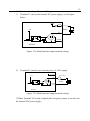
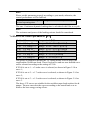
4)Multi-function Input Terminal and FWD, REV Wiring
42
The multi-function input terminals use full-bridge rectifying circuit, as the
below figure shows. PLC is the common terminal for X1~X5, FWD and REV.
The PLC terminal can sink or source current. Wire connections X1~X5, FWD
and REV is flexible and the typical wiring is shown below:
① Connection method 1
It is default to use the inverter’s internal power source 24V, i.e. PLC
connected with P24.
If you want to use external power supply, make sure to remove the wire
between PLC and P24.
+24V
P24
+3. 3V
PLC
+
-
DC
+
Current
R
K
-
X1、X 2 . . . X5
FWD, REV
COM
HV1000
Figure 3-13 External power supply wiring diagram
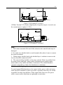
②Connection Method 2
Inverter’s internal +24V power supply is used and the external controller uses
PNP transistors whose common emitters are connected, as shown in Figure
3-14.
43
External controller
HV1000
●
●
●
●
●
P24 D2
+ 24V DC
COM
PLC ●
3.3V
FWD
3 .3V
●
●
●
X5
COM
PE
Shield near the inverter
should be grounded
Figure 3-14 Internal +24V wiring diagram (source)
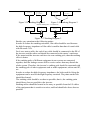
Inverter’s internal +24V power supply is used and the external controller uses
PNP transistors whose common emitters are connected.(Remote the wire
between PLC and P24).
External controller
●
●
HV1000
●
●
●
●
●
P24 D2
+
24V DC
COM
PLC ●
3.3V
FWD
3.3V
●
●
Shield bear the inverter
should be grounded
X5
PE
Figure 3-15 Internal +24V wiring diagram (drain)
When using External power supply, remember to disconnect PLC and P24
44
External controller
HV1000
●
●
9~ 30V
●
+
-
●
●
D2
P 24
+
24V DC
-
COM
PLC
3. 3V
●
FWD
3. 3V
●
X5
●
●
PE
Shield near the inverter
should be grounded
Figure 3-16 External power supply wiring (source)
External power supply wiring (drain)(Remember to disconnect PLC and P24)
External controller
●
HV1000
●
●
+
-
9 ~ 30V
●
●
●
●
P24
D2
COM
+ 24 V
DC
-
3.3 V
PLC ●
FWD
3.3 V
●
●
Shield grounded near
the inverter
X5
PE
Figure 3-17 External power supply wiring (drain)
45
5)Multi-function Output Terminal Wiring
① Terminal Y1 can use the internal 24V power supply, see the figure
below:
+24V
P 24
Relay
+5V
Y1
COM
HV1000
Figure 3-18 Multi-function output terminal wiring 1
② Terminal Y1 can also use external power (9~30V) supply:
+24V
P24
DC 9~30 V
+5 V
Y1
+ -
Relay
COM
HV1000
Figure 3-19 Multi-function output terminal wiring 2
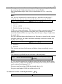
③When Terminal Y2 is used as digital pulse frequency output, it can also use
the internal 24V power supply:
46
HV1000
+ 24V
P 24
+5V
+ 24V
R
Y2
COM
Digital
frequency meter
Figure 3-20 Terminal Y2 wiring 1
④When Terminal Y2 is used as digital pulse frequency output, it can also use
the external power supply (9~30V):
HV1000
+24V
P24
+5V
+24V
Y2
COM
R
+
9~30V
Digital
frequency meter
Figure 3-21 Terminal Y2 wiring 2
Note:
1.Don’t short terminals P24 and COM, otherwise the control board may be
damaged。
2.
Use multi-core shielded cable or multi-strand cable (above 1mm) to connect
the control terminals.
3.When using a shielded cable, the shielded layer’s end that is nearer to the
inverter should be connected to PE。
4.The control cables should be as far away (at least 20cm) as possible from
the main circuits and high voltage cables (including power supply cables,
motor cables, relay cables and cables of contactor). The cables should be
vertical to each other to reduce the disturbance to minimum.
5.2.4 Onsite Wiring Requirements
To avoid mutual EMI disturbance, the control cables, power cable and motor
cable should be installed as apart as possible, especially when they are routed
in parallel for rather long distance. If the signal cable must cross the power
cable or motor cable, keep them at right angle to each other.
47
Motor cable
>50cm
>30cm
Power cable
>20cm
Signal/Control
cable
Power source or motor cable
Signal/Control cable
Figure 3-22 Cable routing schematic diagram
If the section area of the motor cable is too big, the motor should derate. Refer
the inverter’s cable specs in Table 3-2. Since the larger the section area of
cables, the greater their capacitance to the ground, therefore, the output
current should derate 5% with increasing every category of cable section area
Shielded/armored cable: high-frequency low-impedance shielded cable should
be used, such as woven copper mesh, aluminum mesh or metal mesh.
The control cable should be shielded, and the clamps at both ends of the metal
mesh should be connected to the earth terminal of the inverter enclosure.
Use conductive plate and dentate pad to clear away the paint between the
screws and metal casing, to ensure good conductivity.
PE
Enclosure
PE
Enclosure
Figure 3-23 Correct shield layer earthing
PE
PE
Enclosure
Enclosure
Fugure3-24 Incorrect shield layer earthing
5.2.5 Earthing
Independent earthing pole(recommended)
Shared earthing pole(acceptable)
48
Inverter
Other
equipment
Inverter
PE
Other
equipment
PE
Figure 3-25 Earthing Diagram 1
Figure 3-26 Earthing Diagram 2
Shared earthing lines(not allowed)
Inverter
PE
Other equipment
Inverter
Other equipment
PE
Figure 3-27 Earthing Diagram 3
Besides, pay attention to the following points:
In order to reduce the earthing resistance, flat cable should be used because
the high frequency impedance of flat cable is smaller than that of round cable
with the same CSA.
For 4-core motor cable, the end of one cable should be connected to the PE of
the inverter, and the other end should be connected to the motor’s enclosure.
If the motor and the inverter each have its own earthing pole, then the earthing
effect is better.
If the earthing poles of different equipment in one system are connected
together, then the leakage current will be a noise source that may disturb the
whole system. Therefore, the inverter’s earthing pole should be separated with
the earthing pole of other equipment such as audio equipment, sensors and PC,
etc.
In order to reduce the high frequency impedance, the bolts used for fixing the
equipment can be used as the high frequency terminal. The paints on the bolt
should be cleaned。
The earthing cable should be as short as possible, that is, the earthing point
should be as close as possible to the inverter.
Earthing cables should be located as far away as possible from the I/O cables
of the equipment that is sensitive to noise, and lead should also be as short as
possible.
49
6.
Operation Procedures
6.1 Term Definition
6.1.1 Inverter Control modes
There are three control modes:
(1)Keypad control:The inverter is controlled by RUN、STOP key.
(2)Terminal control:The inverter is controlled by FWD、REV and COM
(two-wire mode), Xi (3-wire mode).
(3)Communication:The operations such as START and STOP are controlled
by RS485.
The control modes can be selected by parameters, switched by multi-function
input terminals (function code 27、28、29 of P5.00).
6.1.2 Frequency Setting Method
Methods to set frequency:
(1)▲ and ▼ on the keypad;
(2)Terminal UP/DN;
(3)Serial communication port;
(4)Analog VCI;
(5)Analog CCI;
(6)Terminal (PULSE);
(7)Potentiometer(for power rate lower than 4.G)
How to set frequency:
Main reference frequency: Set by P0.02, multi-speed (MS) or close loop
control.
The main reference frequency is decided by the priority of running mode. The
priority level is Jog>close loop>PLC>MS (multi-speed) >common running,
e.g. if the inverter is running in MS mode, the primary reference frequency is
MS frequency.
Auxiliary reference frequency: set by P0.03、P9.17、P0.05、P9.18.
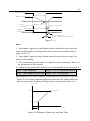
Preset frequency: the sum of main and auxiliary frequency multiply a factor,
which is set in P9.19 and P9.20. Please refer to P9.19, F9.20 and Figure 5-1 in
chapter 5.
6.1.3 Inverter Operation Status
(1)Stop: After the inverter is switched on and initialized, if no operating
command is received or the stop command is executed, then the inverter
enters stop status.
(2)Operating: After receiving run command, the inverter begins to operate.
50
(3)Motor parameter tuning: If P1.10 is set at 1 or 2, after giving RUN
command, the inverter will enter motor parameter tuning status, and then it
will stay in stop status.
6.1.4 Operating Mode
There are 5 kinds of operating modes of HV1000,which can be arranged in
the sequence of:Jog>Close loop operation>PLC>MS>Simple operation
according to the priority.
(1)Jog:When the inverter is in stop status, it will operate according to Jog
frequency after it receives the Jog operation command.(See P9.05~P9.08)
(2)Close-loop operation:If the close-loop operating function is enabled
(P7.00=1) , the inverter will select the close-loop operation mode, meaning
that it will perform PI regulation according to the reference and feedback
values (See explanations of Parameter P7) . Close-loop operating function can
be disabled by multi-function terminal (function No. 20) , and the inverter will
then select other operating mode of lower priority level.
(3)PLC running:PLC function is enabled if the one’s place of PD.00 setting
is a non-zero value. The inverter will run according to the preset mode, see PD
function group. It can be disabled by multi-function terminal (function
No.21) .
(4)MS running:Select multi-frequency 1~7 (P8.00~P8.06) by the
combination of multi-function terminal (function No. 1, 2, 3), which is not
zero.
(5)Simple running: Simple open-loop operation.
The above 5 operating modes determine 5 frequency setting sources. Except
Jog, the other four frequency settings can be adjusted or combined with
auxiliary frequency. The frequency of PLC, MS and simple running can also
be adjusted by traverse.
6.2 Operation Guide
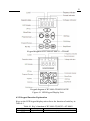
6.2.1 LED Keypad
LED keypad display unit is to receive command and display parameters.
51
Keypad diagram of HV1000-4T-0007G~4T-004G
Keypad diagram of HV1000-4T-0055G/0075P
Figure 4-1 LED Keypad Display Unit
6.2.2 Keypad Function Explanation
Keys on the LED keypad display unit refer to the function of each key in
Table 4-1.
Table 4-1 Key’s function of HV1000-4T-0007G~4T-004G
Key
PRG
Name
Function
Program/Esc key To shift between program state and Esc
52
Key
FUNC/DATA
▲
▼
RUN
STOP/RESET
/
Name
Function
state
To shift between function code menus,
confirm modification
To increase data or function code number
To decrease data or function code number
To scroll over the displayed parameters,
such as voltage、frequency. To select the
Shift key
digit to be modified
In the keypad operating mode, press the key
Run key
to start running
In keypad mode, stop the inverter or reset in
case of alarm or fault;
Stop/Reset key
Terminal control mode: reset in case of
alarm or fault
Potentiometer Set frequency
Function/Data
key
Increase key
Decrease key
Key’s function HV1000-4T-5R5G/7R5P~4T-110G/132P
Key
Name
Function
Program/Esc
MENU/ESC key
To shift between program state and Esc
Function/Dat
ENTER/DATA a key
To enter sub-menu, confirm modification
Increase
▲
To increase data or function code number
key
Decrease
▼
To decrease data or function code number
key
In the edit state, you can select the
Shift key modified bit of set digit; In other state, to
scroll over the displayed parameters.
Control Control mode selection, press
LOCAL
mode
ENTER/DATA to confirm
In panel control mode, press Jog to start
JOG
Jog key
running
In panel control mode, press the key to
RUN
Run key
start running.
Stop/Reset
STOP/RESET
Reset in case of alarm or fault
key
6.2.3 Indicator Description
Functions of the indicators on the keypad:
Indicator
Meaning
Status indicator
ON: the inverter is running
Color
Green
Mark
RUN
53
Indicator
Meaning
ON: current LED display is
Frequency indicator
frequency
ON: current LED display is
Current indicator
current
ON: current LED display is
Voltage indicator
voltage
ON,keypad control mode;
Control mode
OFF: terminal control mode;
indicator
Flicker: communication control
mode
Set frequency by the
Potentiometer
potentiometer
Color
Mark
Green
Hz
Green
A
Green
V
Green LOCAL
Green
None
Implication of the combination of indicators:
Indicator
Meaning
combination
Hz+A
Set speed(r/min)
Set line speed
A+V
(m/s)
Set percentage
Hz+V
(%)
If all the above indicators (A, V, Hz) go out, it means the displayed parameter
has no unit.
6.2.4 Parameter Setting Method
Parameter system
The HV1000 series inverter has 19 function groups: P0~P9, PA, PB, PC, PD,
PE, PL, PN, PP and PU. Each function group includes many parameters,
which is presented as function group number + parameter number, e.g. P7.08.
Menu structure and parameter
When setting parameter through LED keypad display unit, function group is
listed in menu level 1, parameter in menu level 2, and settings of parameters
in menu level 3.
Examples of Parameter Setting
The setting of parameter is presented in decimal (DEC) and hexadecimal
(HEX) format. If it is set in hexadecimal format, each digit of the setting is
independent to one another, which can be 0~F. There are at most 4 digits, they
are: one’s place, ten’s place, hundred’s place and thousand’s place. You may
select certain digit by pressing key, and use ▲and ▼ key to increase or
decrease values.
Example 1:To change the frequency from 50Hz to 40Hz(P0.07:50.00 change
to40.00)
54
1.Press PRG key to enter programming state, the LED displays P0.
2.Press FUNC/DATA key, “P0.00” is displayed. Press ▲ key until “P0.07” is
displayed.
3.Press FUNC/DATA key, you will see 50.00.
4.Press key, to move the cursor to the digit “5”.
5.Press ▼ key once, to change the digit to “4”.
6.Press FUNC/DATA key to save the modification and you will see the next
parameter P0.08.
7.Press PRG key to exit the programming state.
FUNC
DATA
PRG
50 . 00
P0
Enter menu level 1
▼
40. 00
P 0 . 07
P 0 . 00
Enter menu level 2
5 0 . 00
FUNC
DATA
50 . 00
Enter menu level 3
FUNC
DATA
Not
Save save
PRG
PRG
PRG
P 0. 08
-P 0 -
P 0. 07
50 00
.
PRG
PRG
-P 0 -
40 00
.
Example 2:Settings of HEX format:
Take PA.00 (Display parameter during running) for example. Suppose you
hope to display: reference setting, actual speed, set speed, actual line speed
and set line speed.
Since each digit is mutually independent, you may set them separately. First
you should decide the binary value, and then convert it into hex format. The
conversion of binary value to HEX value is shown in Table 5-9.
1.Set one’s place.
Refer to the figure below. Reference Frequency is decided by the BIT2 of the
one’s place of PA.00. If BIT2=1, it means the parameter will be displayed.
For those parameters you don’t want to display, you may set the
corresponding bit at Zero. Therefore, it turns out to be “0100”, after
converting to HEX value, it is 4. So, you should set the one’s place at 4.
2.Set Ten’s place:
Similarly, set the corresponding bit at “1” for those parameters you want to
display, you will get “1111”, i.e. “F”.
3.Set Hundred’s and Thousand’s place:
55
Since no parameters related to hundred’s and thousand’s place are required to
display, so they are set at zero, from the above, FA.00 is set at 00F4.
Thou
Hun
Ten
One
BIT0
BIT1
BIT2
BIT3
:output freq.
:output freq.
: set freq.
:output current
BIT0
BIT1
BIT2
BIT3
:actual speed
:set speed
:actual line speed
:set line speed
BIT0
BIT1
BIT2
BIT3
:output power
:output torque
:reserved
:reserved
BIT0
BIT1
BIT2
BIT3
:reserved
:reserved
:reserved
:reserved
Hz before compensation
Hz after compensation
Hz
A
rpm
rpm
m/s
m/s
%
Under menu level 3, if no digit of a parameter is blinking, it means it is
unchangeable. The possible reasons are:
The parameter is unchangeable, such as measured parameters, operation log,
etc;
The parameter can be changed at stop state only;
The parameter is protected. When PP.01=1 or 2, the parameter is protected.
You should set PP.01=0 to allow the modification.
6.2.5 Speed Setting
If the initial state is actual speed, set speed, actual line speed or set line speed, you may press ▲
or ▼key to change the set speed and set line speed real-time. If you want to change the reference
key to shift the LED display to frequency then change it.
6.2.6 Locking/Unlocking Keypad
setting, press
Lock Keypad: Set the hundred’s place of P9.21 at non-zero value. Press
FUNC/DATA key and PRG key at the same time, thus the keypad is locked.
Figure 4-2 Lock LED keypad display unit
56
Unlock: at stop or operating state, press FUNC/DATA key, and then press ▼
three times. Note that the operation will not change the value of P9.21.
Note:
Even though the hundred’s place of P9.21 is not zero (allow to lock the
keypad), every time the inverter is powered up, the keypad is not locked.
57
7.
Parameters
Note:
The contents in the“【】”are factory default .
7.1 Basic Parameters(P0)
P0.00 Command channel
Range:0~2 【0】
HV1000 has 3 kinds of command channels:
0:LED keypad display unit,use RUN and STOP key on the keypad to control
the inverter.
1:Terminal control: Input operating commands via terminals. Use terminals
FWD, REV, to start and stop the inverter
2:Serial communication port control.
P0.01 Control mode
Range:0~1 【0】
0:Vector control 1
1:Vector control 2
P0.02 Frequency source setting Range:0~6 【0】
0:Digital setting 1, set by ▲or▼ key.
Initial frequency is the value of P0.04 and it can be adjusted via ▲ and ▼keys
on the keypad.
1:Digital setting 2 set by terminal UP/DN.
Initial frequency is the value of F0.02 and it can be adjusted via terminal
UP/DN.
2:Digital setting 3, set through serial communication port
Initial frequency is the value of P0.04 and it can be adjusted via serial
communication port.
3:VCI
The reference frequency is set by voltage input via terminal VCI and the input
voltage range is DC 0~10VDC.。
4:CCI
The reference frequency is set by voltage or current input via terminal CCI
and the input range is DC 0~10 VDC (if jumper CN7 (SW1) is placed at V
side) or DC0~20mA (if jumper CN7 (SW1) is placed at I side).
5:Terminal Pulse Setting
The reference frequency is set by terminals X4 or X5, see P5.03~P5.04. The
input pulse range: 15~30V, 0~50.0 kHz.
58
6:Keypad Potentiometer Setting (for power rate lower than
HV1000-4T-004G)
The reference frequency is set by potentiometer, the adjusting range is 0~
Max (P0.09).
Note:
For method 3, 4 and 5, the frequency calculation curve is given in
P5.10~P5.21, please refer to 5.5.
P0.03 Auxiliary reference frequency
Range:00~13 【0】
The setting frequency of HV1000 is composed of main reference frequency
and auxiliary reference frequency. P0.03、P0.05、P9.17、P9.18 are used to
define auxiliary reference frequency. Figure 5-1 shows the formation process
of setting frequency.
Figure 5-1 Preset Freq. Calculation Method
Figure 5-2 Auxiliary Frequency Processing
Table 5-1 Auxiliary reference frequency method selection
Method
Name
Description
0
invalid
Auxiliary freq.=0
1
Adjust by ▲ and ▼
Set by P0.05
2
Adjust UP/DN
3
Set by serial port
4
VCI
Depending on actual input.
Refer to P5. 10
5
CCI
59
Method
6
7
8
9
10
11
12
13
Name
Description
PULSE
- VCI
- CCI
- PULSE
VCI-5
CCI-5
PULSE-0.5×Max pulse input
freq.
Potentiometer(for power rate
lower than HV1000-4T-004G)
Select digital setting 3, you may set P0.03 via serial port to change auxiliary
frequency.
If VCI-5 or CCI-5 is selected, take 5V input as the point corresponding to zero
frequency, 0~5V input corresponds to negative output, 5~10V input
corresponds to positive output. See Figure5-3.
Auxiliary freq.
0.5fmax
0
5
10
V
-0.5fmax
.
.
fmax—frequency corresponding to Max analog value(P5.17 or O5.21)
Figure 5-3 Frequency Setting Via VCI-5 or CCI-5
If PULSE-0.5 × P5.13 is taken as auxiliary frequency setting method, one half
of P5.13 (max. pulse freq.) as the point corresponding to zero frequency,
0~0.5 times of F1.03 input corresponds to negative output, 0.5~1 times of
P5.13 input corresponds to positive output. See Figure5-4.
Auxiliary freq.
0.5fmax
0
Pmid
F 1 .03 Pulse
-0.5fmax
.
.
Pmid—1/2*P5.13
fmax—frequency corresponding to Max analog value (p5.17 or P5.21)
Figure 5-4 PULSE-0.5 × P5.13 As Freq. input
60
F9.17: Analog auxiliary reference factor
It is valid when F0.03=4~12. The auxiliary reference undergoes F9.17 gain
calculation first, and then output according to F5.10.
P9.18: digital auxiliary reference control
It is valid when P0.03=1~3. See Figure 5-5.
Figure 5-5 Digital Auxiliary Freq. Setting
One’s place of P9.18
0: save the auxiliary freq. at power off
The auxiliary frequency will be saved in P9.03, and the sign of the freq. saved
in P9.18.
1: not save the auxiliary freq. at power off
Ten’s place of P9. 18
0: maintain the auxiliary freq. if the inverter stops
1: preset frequency is cleared if the inverter stops
Hundred’s place of P9.18: sign of auxiliary freq.
0: (+) positive sign.
Preset freq. is the sum of main freq. and auxiliary freq.
1: (-) negative sign
Preset freq. is the result of main freq. minus auxiliary freq.
Note:
When the inputting mode of auxiliary reference frequency is the same with
that of main reference frequency, the auxiliary reference frequency setting is
invalid.
61
P0.04 Keypad digital setting Range:Lower limit of freq.~Upper limit
of freq.【50.00Hz】
When the frequency source setting method is defined as keypad digital
setting(P0.02=0、1、2), P0.04 is the initial value of frequency.
P0.05 Digital auxiliary
Range:0.00~650.00Hz 【0.00Hz】
frequency
P0.05:The initial value of digital auxiliary frequency.
It is valid only and it is the initial value of auxiliary frequency when
P0.03=1~3.
P0.06 Base frequency
Range:0.00~650.00Hz 【50.00Hz】
P0.07 Upper limit of freq.
Range:Upper limit~Max output freq.
【50.00Hz】
P0.08 Lower limit of freq.
Range:0~Upper limit of freq.
【0.00Hz】
Please refer fH and fLin Figure 5-6
P0.09 Max output frequency
P0.10 Max output voltage
Range:Max{50.00, P0.12 upper limit
of frequency}~650.00H【50.00Hz】
Range:1~480V 【Inverter’s rated】
The max frequency refers to the allowed max output frequency of the inverter.
Refer to the fmax in Figure 5-6;
Base frequency normally corresponds with the rated frequency of the motor. It
is the Min frequency when the inverter outputs the highest voltage, as shown
in Figure 5-6 as fb
Max output voltage is the inverter’s output voltage when the inverter outputs
base frequency, as shown in Figure 5-6 as Vmax. This corresponds to the rated
voltage of the inverter
Output voltage
Vmax
fL
Output Frequency
fb fH fmax
Figure 5-6 Characteristic parameters definition
The fH and fL are defined by P0.07 and P0.08 as upper limit and lower limit of
frequency respectively.
62
P0.11 Running directions
【0】
Range:0、1
The function applies only to keypad control, but not serial port control, not
terminal control mode.
0:Forward
1:Reverse
P0.12 Acc time 1
P0. 13 Dec time 1
Range:0.1~3600s(min)【6.0s/20.0S】
Range:0.1~3600s(min)【6.0s/20.0S】
Output frequency
fmax
Time
t2
t
1
Figure 5-7 Acc/Dec time definition
Acc time is the time taken for the motor to accelerate from 0 Hz to the
maximum frequency (as set in P0.09), see t1 in Figure 5-7. Dec time is the
time taken for the motor to decelerate from maximum frequency (P0.09) to 0
Hz, see t2 in Figure 5-7.
HV1000 has four pairs of acc/dec time. Here we only introduce acc/dec 1.
Please find acc/dec time 2~4 in section 5.9: P8.14~P8.19
P0.14 Anti-reverse setting
range:0、1【0】
0:Reverse allowed
1:Reverse not allowed
7.2 Motor Parameter(P1)
P1.00 Model
Range:0、1【0】
0:G model(Constant torque)
1:P model(Pump & Fan)
Note:
For power rate lower than HV1000-4T-004G,P1.00 is reserved.
P1.01
P1.02
P1.03
Motor’s poles Range:2~14【4】
Rated power Range:0.4~999.9kW【depending on model】
Rated current Range:0.1~999.9A【depending on model】
63
P1.01~P1.03 are to set motor’s parameters. Be sure to input the values
according to motor’s nameplate.
P1.04 Current without
Range:0.1~999.9A【depending on model】
load
Range:0.0~50.00%【depending on
P1.05 Stator resistance
model】
Range:0.0~50.00%【depending on
P1.06 Leakage
inductance
model】
Range:0.0~50.00%【depending on
P1.07 Rotor resistance
model】
Range:0.0~2000.0%【depending on
P1.08 Mutual inductance
model】
Please refer the above parameters to Figure 5-8.
R1
I1
1
U
R2
jX1l
Rm
I0 Xm
jX2l
I2
1-S 2
S R
Figure 5-8 Motor’s Equivalent Circuit
In Figure 5-8, R1, X1l, R2, X2l, Xm and I0 represent stator’s resistance,
stator’s leakage inductance, rotor’s resistance, rotor’s leakage inductance,
mutual inductance and current without load respectively. The setting of P1.06
is the sum of stator’s leakage inductance and rotor’s inductance.
The settings of P1.05 ~P1.08 are all percentage. Formula used for calculating
stator’s resistance or rotor’s resistance::
%R
R
100%
V / 3I
R:Stator’s resistance or rotor’s resistance that is converted to the stator’s side;
V:Rated voltage;
I:Motor’s rated current;
Formula for calculating (leakage inductance or mutual inductance);
%X
X
100%
V / 3I
X:The sum of leakage inductance of stator and rotor, or mutual inductance.
The rotor’s inductance has been converted to the stator’s side;
V:Rated voltage;
I:Motor’s rated current
64
If motor’s parameters are available, please set P1.05 ~P1.08 to the values
calculated according to the above formula.
If the inverter performs auto-tuning of motor’s parameters, then the settings of
P1.04~P1.08 after the auto-tuning process will be updated.
After motor power (setting of P1.02) is changed, the inverter will set
P1.03~P1.08 to corresponding parameters.
P1.09 Rated slip frequency Range:0.00~20.00Hz【2.00Hz】
Motor’s rated slip frequency can be calculated by the motor’s rated speed (on
the nameplate):
Rated slip frequency = motor’s rated frequency (i.e. basic operating frequency
P0.06) × (motor’s synchronous speed-motor’s rated speed) ÷motor’s
synchronous speed. Where: motor’s synchronous speed = motor’s rated
frequency × 120÷number of motor’s poles (P1.01)
After setting the slip frequency, the slip compensation will be enabled by
P3.09~P3.11.
P1.10 Auto tuning
Range:0~2【0】
FH09 can be used to measure and write-in the motor’s parameters
automatically.
0: Auto-tuning is disabled
1: Stationary auto-tuning (Start auto-tuning to a standstill motor
Before starting auto-tuning, values on the motor’s nameplate must be input
correctly (P1.01~P1.03). When starting auto-tuning to a standstill motor, the
stator’s resistance, rotor’s resistance and the leakage inductance will be
measured and the measured values will be written into P1.05, P1.06 and P1.07
automatically.
2:Rotating auto-tuning
When starting a rotating auto-tuning, at first, the motor is in standstill status,
and the stator’s resistance , rotor’s resistance and the leakage inductance will
be measured, and then the motor begins to rotate, mutual inductance,
parameters will be measured and written into P1.05, P1.06, P1.07, P1.08 and
P1.04 automatically.
After auto-tuning, P1.10 will be set to 0 automatically.
Auto-tuning procedures:
1)Set the “P0.06 basic operating frequency” and “P0.07 Max output voltage”
correctly according to the motor’s feature;
2)Set the P1.01, P1.02 and P1.03 correctly;
3)If P1.10 is set to 2, Acc time (P0.12) and Dec time (P0.13) should be set
correctly and remove the load from the motor and check the safety;
4)Set P1.10 to 1 or 2, press FUNC/DATA, and then press RUN to start
auto-tuning;
65
5)When the operating LED turns off, that means the auto-tuning is over.
Note:
1.When setting P1.10 to 2, you may increase Acc/Dec time if over-current or
over-voltage fault occurs in the auto-tuning process;
2.When setting P1.10 to 2, the motor’s load must be removed before starting
rotating auto-tuning;
3.The motor must be in standstill status before starting the auto-tuning,
otherwise the auto-tuning cannot be executed normally;
4.If it is inconvenient to start auto-tuning (e.g. the motor cannot break away
from the load), or you don’t require much on motor’s control performance,
you can use stationary auto-tuning or even disable the function. You may
input the values on the motor’s nameplate correctly (P1.01~P1.03);
5.If the auto-tuning function is unavailable and there is motor’s parameters on
the nameplate, you should input the values correctly (P1.01~P1.03), and then
input the calculated values (P1.04~P1.08). Please set the parameters correctly;
6.If auto-tuning is not successful, the inverter alarms and displays fault F.tU.
7.3 Start/Brake Parameter(P2)
P2.00 Start mode
Range:0、1、2【0】
P2.00=0:Start at start frequency
The inverter is started at start frequency(P2.01)and in preset time(P2.02).
P2.00=1:Brake first and then start at start frequency.
DC brake first, refer to P2.03、P2.04, and then start in the manner of P2.00=0
P2.00=2: Rotate speed tracking and then start at start frequency(For power
rate lower than HV1000-4T-004G,P2.00 is reserved)
Tracking motor’s rotate speed and directions automatically. Start the motor
during rotating smoothly and without any impact. Please refer to Figure 5-a.
66
Power supply
Closed
Open
Closed
Rotate speed
0
Output
frequency
Forward
Running
direction
Reverse race
Reverse
Detect motor’s
Rotate speed and direction
Figure 5-a
Note:
1.Start mode 1 applies to small-inertia motor when the inverter stops, the
motor is still rotating. For large-inertia load, do not restart until the motor
stops.起动方式 1
2.Start mode 2 applies to large-inertia motor when the inverter stops, the
motor is still running.
3.The performance of start mode 2 is related to motor parameters. Please set
the parameters of PH correctly.
4.When driving synchronized motor, it is recommended to use start mode 0.
P2.01 Start frequency
Range:0.20~60.00Hz【0.20Hz】
P2.02 Start frequency hold time Range:0.0~10.0s【0.0s】
Start frequency refers the frequency at which the inverter starts, as shown in
Figure 5-9 as fS. Start frequency hold time refers the time within which the
inverter runs at start frequency during start up, as shown in Figure 5-9 t1:
Freq.(Hz)
fmax
fs
Time
t1
Figure 5-9 Relation of Start Freq. and Start Time
67
Note:
The start frequency is not limited by lower limit of the frequency.
P2.03 DC brake current at startup
P2.04 DC brake time at startup
Range:Depending on model【0.0
%】
Range:Depending on model
【0.0s】
P2.03 and P2.04 are valid only when you set P2.00=1, that is, braking before
starting. See Figure 5-10.
DC brake current at startup is determined by inverter model,
4.0KW and below G type:0~150%;P type:0~130%。
5.5KW and above G type:0~100%;P type:0~80%。
DC braking current start up is relative to the percentage of the rated current of
the inverter.
If the brake time at startup is set to 0.0s, no brake process.
Output
frequency
Time
Output
voltage
Braking
energy
(effective
value)
Time
DC braking time
Running
command
Figure 5-10 Start mode 1
P2.05 Acc/Dec
Range:0、1【0】
P2.05=0:Linear Acc/Dec
The output frequency increase or decrease according to a fixed slope, see
Figure 5-11.
P2.05=1:S curve Acc/Dec
The output frequency increase or decrease according to S curve, see Figure
5-12.
68
Frequency
fmax
Time
t1
t2
Figure 5-11 Linear Acc/Dec curve
Frequency
3
f max
3
2
2
1
1
t1
t2
Time
Figure 5-12 Acc/Dec S curve
P2.06 S curve start time
P2.07 S curve rising time
Range:10~50%【20.0%】
Range:10~80%【60.0%】
P2.06、P2.07are only valid when F2.05=1 (S curve mode) and P2.06+P2.07 ≤
90%.
S curve start time is illustrated in Figure 5-12 as ①, the change rate of output
frequency is increasing from 0.
S curve rising time is illustrated in Figure 5-12 as ②, the change rate remains
the same.
S curve end time is illustrated in Figure 5-12 as ③. The change rate decreases
to 0.
S curve Acc/Dec is suitable to the start and stop of elevator, conveyer, etc.
P2.08 Stop mode
Range:0、1、2【0】
0:Decelerate to stop
When the inverter receives Stop command, it will reduce output frequency to
zero and stop within preset deceleration time.
1:Coast to stop
When the inverter receives Stop command, it will stop outputting frequency
and stop gradually relying on load inertia.
2:Deceleration + DC braking
69
When the inverter receives Stop command, it will reduce output frequency
within preset Dec time. When it arrives at the frequency threshold of DC
braking, the DC braking begins. Please refer to P2.09~P2.12.
Range:0.00~60.00Hz
P2.09 Frequency threshold of DC braking
【1.00Hz】
P2.10 DC brake delay time
Range:0.00~10.00s【0.00s】
Range:Depending on model
P2.11 DC brake current
【120.0%/100.0%】
Range:Depending on model
P2.12 DC brake time at stop
【0.5s】
DC braking delay time is the period from arriving at frequency threshold
(P2.09) to starting braking.
During the period, there is no output from the inverter. This function can
prevent current overshoot of high power motor at startup.
For power rate lower than HV1000-4T-004G:
The braking current is different depending on inverter’s model, G type:
0~150% of inverter’s rated current (max. current among the 3 phases), P type:
0~130% of inverter’s rated current (max. current among the 3 phases).
For power rate higher than HV1000-4T-0055G/0075P:
The braking current is different depending on inverter’s model, G type:
0~150% of inverter’s rated current (max. current among the 3 phases), P type:
0~130% of inverter’s rated current (max. current among the 3 phases).
If the brake time at stop is set at 0.0s, there is no braking process.
Output Freq.
Initial Freq. of braking
Output voltage.
(RMS value)
Waiting time
Braking energy
Braking time
Operating
command
Figure 5-13 Deceleration +DC braking Process
P2.13 Dynamic braking
0:Disabled
1:Enabled
Range:0,1【0】
70
Note:
Please set this parameter properly according to your needs, otherwise, the
control performance will be suffered.
P2.14 Ration of braking time Range:0.0~100.0%【100.0%】
to total operating time
The max. Continuous dynamic braking time is calculated with 100s as a cycle.
Note:
The resistance and power of the braking resistor should be considered.
7.4 Flux vector control parameters(P3)
P3.00
P3.01
P3.02
P3.03
P3.04
P3.05
P3.06
V/F curve setting
V/F freq. F3
V/F voltage V3
V/F freq. F2
V/F voltageV2
V/F freq. F1
V/F voltageV1
Range:0~3【0】
Range:P3.03~P0.06【0.00Hz】
Range:P3.04~100.0%【0.0%】
Range:P3.05~P3.01【0.00Hz】
Range:P3.06~P3.02【0.0%】
Range:0~P3.03【0.00Hz】
Range:0~P3.04【0.0%】
This group of parameters defines the V/F setting modes so as to satisfy the
requirements of different loads. Three fixed curves and one user-defined curve
can be selected according to the setting of P3.00.
If P3.00 is set to 1,a 2-order curve is selected, as shown in Figure 5-14 as
curve 1;
If P3.00 is set to 2,a 1.7-order curve is selected, as shown in Figure 5-14 as
curve 2;
If P3.00 is set to 3,a 1.2-order curve is selected, as shown in Figure 5-14 as
curve 3.
The above V/F curves are suitable for the variable-torque loads such as fan &
pumps. The user can select the curves according to the actual load so as to
achieve the best energy-saving effects.
71
Figure 5-14 Torque-reducing curve
If P3.00 is set to 0, you can define a curve by P3.01~P3.06, i.e. a polygonal
line defined by 3 points (V1, F1), (V2, F2), (V3, F3), to satisfy the needs of
special loads, as shown in Figure 5-15.
The default is a straight line, shown in Figure 5-14 as curve 0.
Volt.
100%
V3
V2
V1
F1
F2
F3
Fb
Freq.
V1~V3: segment 1-3,voltage percentage
F1~F3: frequency segment 1-3
Fb: base frequency F0.06
Figure 5-15 User Defined V/F curve
P3.07 Torque boost
Range:0~30.0%【0.0%】
In order to compensate the torque drop at low frequency, the inverter can
boost the voltage so as to increase the torque. If F0.09 is set to 0, auto torque
boost is enabled and if set at non-zero, manual torque boost is enabled, as
shown in Figure 5-16.
72
Output voltage
Vmax
Vb
fz
fb
Output freq.
Vb:manual torque boost
Vmax:Max output volt.
Fz:cut-off freq.for torque boost fb:Basic output freq.
Figure 5-16 Torque boost (shadow area: boost value)
Note:
1.Wrong parameter setting can cause overheating of the motor or triggers the
over-current protection of the inverter.
2.Refer to P3.08 for definition of fz.
3.When using synchron motor, you should select manual torque boost, and
adjust V/F curve according to the motor parameters and application.
P3.08 Manual torque boost
Range:0~50%【10.0%】
cutoff point
P3.08 defines the ratio of the cut-off frequency used for manual torque boost
to the base frequency (defined by P0.06) , as shown in Figure 5-16 as fz. This
cut-off frequency adapts to any V/F curve defined by P3.00.
P3.09 Slip compensation gain Range:0.0~300.0%【100.0%】
P3.10 Slip compensation limit Range:0.0~250.0%【200.0%】
P3.11 Compensation time
Range:0.1~25.0s【2.0s】
The change in motor torque will affect motor slip and result in speed change.
Through slip compensation, the output frequency can be adjusted according to
motor load torque, so as to reduce speed change caused by load change. See
Figure 5-17.
Slip
Positive slip
compensation
-100%
100%
Motor’s
load
Negative slip
compensation
Figure 5-17 Auto slip compensation
Electromotion state: Increase the gain of slip compensation gradually when
the actual speed is lower than the reference speed (P3.09)
73
Power generation state: Increase the gain of slip compensation gradually when
the actual speed is higher than the reference speed (P3.09).
Slip compensation range: limit of slip compensation (P3.10) × rated slip
(P1.09).
Note:
The value of automatically compensated slip is dependent on the motor’s
rated slip; therefore the motor’s rated slip must be set correctly (P1.09).
P3.12 AVR function
Range:0、1、2【2】
0:Disabled
1:Always enabled
2:Disabled during decelerating
AVR: auto voltage adjustment. This function can keep constant output voltage
when the input voltage deviates from rated value. Therefore, the function
should be enabled all the time especially when the input voltage is higher than
the rated value.
If AVR is disabled during deceleration, the Dec time is shorter but the current
is higher, otherwise, the motor decelerates smoothly with lower current, but
the Dec time is longer.
P3.13 Auto energy saving
Range:0、1【0】
0:Disabled
1:Enabled
The inverter can detect load current and adjust voltage accordingly to save
energy.
Note:
This function is preferable to the load such as fan and pump.。
P3.14
Motor stabilization factor
Range:0~255【Depending on
model】
P3.14 is used to suppress the oscillation caused by the inverter and the motor.
If the inverter’s output current changes constantly at fixed load, the oscillation
can be reduced by adjusting P3.14.
For power rate lower than 55kW, the default value is 10;
For power rate higher 55kW, the default value is 20.
7.5 Current vector control parameter(P4)
P4.00
Reserved
-
74
P4.01 Pre-excitation
0:Valid
1:Invalid
P4.02 Speed loop proportional
gain 1
Range:0~1【1】
Range:0~65535【120】
P4.03
P4.04
gain 2
Speed loop integral gain 1 Range:0~65535【3】
Speed loop proportional
Range:0~65535【120】
P4.05
Speed loop integral gain 2 Range:0~65535【3】
P4.06 Speed loop switching
frequency
P4.07 D axis current loop
proportional gain
P4.08
gain
D axis current loop integral
Range:0.0%~100.0%【3】
Range:0~65535【10000】
Range:0~65535【2000】
P4.09 Q axis current loop
proportional gain
Range:0~65535【10000】
P4.10 Q axis current loop
integral gain
Range:0~65535【2000】
7.6 Multi-function terminal(P5)
P5.00
P5.01
P5.02
P5.03
P5.04
P5.05
P5.06
P5.07
Function of multi-function terminal X1
Function of multi-function terminal X2
Function of multi-function terminal X3
Function of multi-function terminal X4
Function of multi-function terminal X5
(Reserved)
(Reserved)
(Reserved)
Range:0~43【0】
Range:0~43【0】
Range:0~43【0】
Range:0~47【0】
Range:0~48【0】
75
The multi-function terminals can realize various functions. You may assign
functions to them by setting parameters P5.00~P5.04. Please refer to Table
5-3. Take X1~X3 for example in the following description.
Table 5-2 Functions of multi-function terminals
Setting
Functions
Setting
Functions
0
No function
1
MS frequency 1
2
MS frequency 2
3
MS frequency 3
4
Acc/Dec time 1
5
Acc/Dec time 2
External fault
External fault normally-closed
6
7
normally-open input
input
8
Reset signal
9
Forward jog
10
Reverse jog
11
Coast-to-stop input
Frequency
12
13
Frequency decrease(DN)
increase(UP)
14
PLC operation pause
15
Acc/Dec prohibit
3-wire operation
External interrupt signal
16
17
control
normally-open input
External interrupt
DC injection braking
18
19
signal normally-close
command
input
20
Disable close-loop
21
Disable PLC
Frequency setting
22
23
Frequency setting method 2
method 1
Frequency setting
Reference freq. is input via
24
25
method 3
CCI
Terminal control mode is
26
Reserved
27
forcibly enabled
28
Control mode 1
29
Control mode 2
30
MS close-loop 1
31
MS close-loop 2
32
MS close-loop 3
33
Start traverse operation
Reset the traverse
34
35
External stop command
operation status
36
Reserved
37
Inverter operation prohibiting
38
Reserved
39
Clear length
Clear auxiliary
40
41
Reset PLC stop status
reference frequency
42
Clear counter’s record
43
Signal of triggering counter
Input the signal of
44
45
Pulse input
length
Speed measuring input SM1
Single phase speed
46
47
measuring
(only for X4)
48
Speed measuring input
76
Setting
Functions
SM2(only for X5)
Setting
Functions
The functions are explained as follows:
1~3: MS terminals
If any three of P5.00~P5.02 are set at 1, 2, 3 respectively, Up to 8 segments of
speed can be defined through the combination of the ON and OFF state of the
3 terminals.
Table 5-3 MS Speed
X3
X2
X1
Freq.
OFF
OFF
OFF
Common freq.
OFF
OFF
ON
MS freq. 1
OFF
ON
OFF
MS freq. 2
OFF
ON
ON
MS freq.3
ON
OFF
OFF
MS freq.4
ON
OFF
ON
MS freq. 5
ON
ON
OFF
MS freq. 6
ON
ON
ON
MS freq. 7
The MS frequency will be used in MS running and simple PLC operation. e.g.:
Set the parameters corresponding to X1, X2 and X3: P5.00=1, P5.01=2,
P5.02=3, then X1, X2 and X3 are used to perform MS running. See Figure
5-18.
Speed7
Speed6
Output freq.
Speed5
Speed4
Speed3
Common
Operating
freq.
Operation
command
Speed2
Speed1
Time
X1
X2
X3
Figure 5-18 MS Running
Figure 5-19 illustrated the wiring of terminal control of MS running. K4 and
K5 control the running direction. The combination of K1, K2 and K3 can
enable common running or MS running with 1~7 speeds.
77
Figure 5-19 Wiring of MS running
4~5:Acc/Dec time terminal
Table 5-4 Acc/Dec Time Selection
X2
X1
Acc/Dec time selection
OFF
OFF
Acc time 1/ Dec time1
OFF
ON
Acc time 2/ Dec time 2
ON
OFF
Acc time 3/ Dec time 3
ON
ON
Acc time 4/ Dec time 4
By combination of the ON/OFF state of Terminal 1 and 2, you can get 4
groups of Acc/Dec time.
6~7: External fault signal (normally-open/close input)
If the setting is 6~7, fault signal of external equipment can be input via the
terminal, which is convenient for the inverter to monitor the fault of external
equipment. Once the inverter receives the fault signal, it will display “F.ED”.
The fault signal has two input modes, i.e. normally-open and normally-close.
Figure 5-20 Normally-open/close input
In Figure 5-20, X4 is normally open input and X5 normally close input. KM is
external fault relay.
8: Reset
78
If any of P5.00~P5.04 is set at 8, the inverter can be reset via the terminal
when the inverter has a fault. The function of this terminal is the same with
the RESET key on the keypad.
9~10: External jog command (JOGF/JOGR)
If any of P5.00~P5.04 is set at 9~10, the terminal can enable the jog operation.
JOGF is terminal for forward jog operation command and JOGR is terminal
for reverse jog operation command. Jog frequency, jog interval and jog
Acc/Dec time are defined in P9.05~P9.08.
11: Coast to stop
This function is the same with P2.08, however, it is realized by terminal and
convenient for remote control.
12~13: Frequency increase (UP) /decrease (DN)
If the setting is 12~13, the terminal can be used to increase or decrease
frequency instead of ▲and ▼ keys on the panel for remote control. This
terminal is valid when P0.00=1 or P0.03=2. Increasing or decreasing rate is
determined by P5.09.
14: Pause command for simple PLC:
If the setting is 14, the terminal is used to pause the PLC operation and the
inverter operates at zero frequency when the terminal is enabled, but the
running time is not counted. If the terminal is disabled, the inverter will start
at start frequency and continue the PLC operation. Refer to PD.00~PD.14 for
the use of this terminal.
15: Acc/Dec prohibit
The motor is immune to any external command except Stop command and
maintain the present speed.
Note:
This function is disabled during normal decelerating to stop.
16: 3-wire operation control
Refer to P5.08.
17~18: External interrupt signal normally-open input
When the inverter receives an interrupt signal during running, it will stop
outputs and run at zero frequency. Once the signal removed, the inverter will
resume previous running at start frequency.
As Figure 5-20 shows, there are X4, normally open contacts and X5, normally
closed contact.
Note:
Different from function 6~7, the external interrupt signal will not cause alarm,
and the inverter will resume previous running once the signal removed.
19: DC Braking (DB)
79
If the setting is 19, the terminal can be used to perform DC injection braking
to the motor that is running for emergency stop and accurate location. Initial
braking frequency, braking delay time and braking current are defined by
P2.09~P2.11. Braking time is decided by the bigger value between P2.12 and
the period that the terminal is effective.
20: Disable close-loop
If the setting is 20, the terminal can be used to realize the flexible switching
between close-loop operation and low level operating mode.
When the inverter is switched to low level operating mode, its start/stop,
operating direction, ACC/Dec time are shifted to the corresponding operating
modes accordingly.
21: Disable PLC
If the setting is 21, the terminal is used to realize the flexible switching
between PLC operation and low level operating mode.
When the inverter is switched to low level operating mode, its start/stop,
operating direction, ACC/Dec time are shifted to the corresponding operating
modes accordingly.
22~24: Reference frequency setting method
Through the combination of the ON/OFF state of X1, X2 and X3, you can
select different frequency setting method, which will come into effect
regardless of P0.02.
Table 5-5 Frequency Setting Mode Selection
X3
X2
X1
Mode
OFF
OFF
OFF
None
OFF
OFF
ON
Digital setting 1
OFF
ON
OFF
Digital setting 2
OFF
ON
ON
Digital setting 3
ON
OFF
OFF
VCI analog setting
ON
OFF
ON
CCI analog setting
ON
ON
OFF
Pulse
ON
ON
ON
LED keypad
25: Frequency reference is input via terminal CCI
If the setting is 25, the frequency reference will be input via terminal CCI
forcibly. The frequency input will be changed to the previous one if this
terminal function is disabled.
26:Reserved
27:Terminal control mode is enabled
When this terminal function is enabled, the operating command is input
through this terminal forcibly. The inverter will be controlled in the previous
mode if FWD/REV terminal function is disabled.
28~29:Control mode selection X1~X2
80
Table 5-6 Control Mode Selection
X2
X1
Control mode
OFF
OFF
None
OFF
ON
LED keypad
ON
OFF
Terminal
ON
ON
Serial port
The selection of control mode is realized by the combination of ON/OFF state
of any two of X1~X5. In the above table, you should set P5.00=28, P5.01=29.
30~32: MS close-loop terminal (3 terminals of X1~X5)
设
X3
OFF
OFF
OFF
OFF
ON
ON
ON
ON
Table 5-7 MS Close-loop Setting Selection
X2
X1
MS close-loop reference
OFF
OFF
By P5.01
OFF
ON
MS close-loop setting 1
ON
OFF
MS close-loop setting 2
ON
ON
MS close-loop setting 3
OFF
OFF
MS close-loop setting 4
OFF
ON
MS close-loop setting 5
ON
OFF
MS close-loop setting 6
ON
ON
MS close-loop setting 7
The various MS close-loop setting is realized by the combination of ON/OFF
state of terminal X1~X3. In the above table, you should set P5.00=30,
P5.01=31,P5.02=32
33: Start traverse operation
If the traverse operation is set to be manual start, then traverse function is
enabled if this function is selected. Refer to F6.
34: Traverse reset
If traverse operation is enabled, closing the terminal can clear the information
about traverse status no matter the inverter is in auto or manual start mode.
Traverse operation continues after this terminal is disconnected. See PC.
35: External Stop command
This Stop command is valid to all control modes. When this function is
enabled, the inverter will stop as specified P2.08.
36:Reserved
37: Prohibit inverter from operating
If this function is enabled, the inverter that is operating will coast to stop and
the inverter ready to run will be prohibited to start. This function is mainly
used as safety protection.
38:Reserved
39:Clear the length information
81
The setting of PC.09 (length) will be cleared to zero.
40: Clear the setting of auxiliary reference frequency
This function is valid for auxiliary reference frequency (P0.03=1, 2 and 3) to
clear it to zero, so that the reference frequency is determined solely by main
reference.
41: Reset PLC state
When the inverter stops in PLC mode, the memorized PLC operating
information (operating stage, operating time, operating frequency, etc.) will be
cleared.
42: Clear the counter to zero
This function is to clear the counter to zero and is used in conjunction with
function 43.
43: Input signal to trigger the counter
When the setting is 43, this terminal is used to input counting pulse signal to
the internal counter of the inverter. The max. pulse frequency is 200Hz. The
present counting value can be saved at power off. See P6.10 and P6.11 for
details.
44: Input the signal of length
This function is only effective to multi-function input terminals X4 and X5.
The terminal is used in fixed-length control. Length is calculated by input
pulses. See PC.08~PC.13 for details.
45:Pulse frequency input
This function is effective only to multi-function input terminals X4 and X5.
The terminal is used to input pulse signal that is used as frequency reference.
Refer tp F1 parameters for the relationship between input pulse frequency and
the reference frequency.
46: Single-phase speed measuring input
This function is effective only to multi-function input terminalsX4 and X5.
See section 3.2.3 for input characteristics. The speed control accuracy is
±0.1%. Single-phase speed feedback control can be realized by using this
terminal and PG.
47: Speed measuring input SM1
48: Speed measuring input SM2
This function is effective only to multi-function input terminals X4 and X5.
See section 3.2.3 for input characteristics. The speed control accuracy is
±0.1%. 2-phase speed feedback control can be realized by using this terminal
and PG.
82
Note:
When the inverter is in motor auto-tuning status, No. 44~47 functions of X4
are disabled automatically.
P5.08 Terminal control mode
Range:0~3【0】
This parameter defines four operating modes controlled by external terminals.
0:2-wire operating mode 1
HV1000
K2 K1 Command
Stop
0 0
REV
1 0
0 1
FWD
1
Stop
1
.P24
.
K1
K2
PLC
FWD
.
REV
. COM
.
Figure 5-21 2-wire Operation Mode 1
1:2-wire operating mode 2
HV1000
K2 K1
0 0
Command
.P24
Stop
Stop
1
0
0
1
FWD
1
1
REV
.
K1
K2
PLC
FWD
.
REV
. COM
.
Figure 5-22 2-wire Operation Mode 2
2:3-wire operating mode 1
83
Figure 5-23 3-wire Operation Mode 1
SB1:Stop button;SB2:Run forward button;SB3:Run reverse button
Terminal Xi is the multi-function input terminal of X1~X5. For this case, the
corresponding parameter should be set at 16 (3-wire operation).
3:3-wire operating mode 2
SB2
K
Running direction
0
FWD
1
REV
SB1
K
. P24
.
PLC
HV1000
.
FWD
. Xi
. REV
. COM
Figure 5-24 3-wire Operation Mode 2
SB1:Stop button;SB2:Run button
Terminal Xi is the multi-function input terminal of X1~X5. For this case, the
corresponding parameter should be set at 16 (3-wire operation).
Note:
In terminal control mode, for 2-wire operating mode 1 and 2, although the
terminal is effective, the inverter will not run if there is external stop
command. If you want to start the inverter, you should activate FWD/REV
terminal again, e.g. set any of P5.00~P5.04 at 11 or 35, PLC stop after single
cycle, stop after preset length arrival, Stop key pressed (see P9.21). When the
inverter stops due to a fault, it will start immediately if the terminal
FWD/REV is enabled and the fault is cleared.
P5.09 UP/DN rate
Range:0.01~99.99Hz/s【1.00Hz/s】
84
To define the increase/decrease rate when using UP/DN terminal to change
reference frequency.
Range:000~111【000】
P5.10 Freq. Curve selection
P5.11 Gain of reference frequency
selector
P5.12 Filter constant
Range:0.00~9.99【1.00】
Range:0.01~50.00s【0.50s】
Range:0.1~50.0kHz
【10.0kHz】
P5.13 Max. input pulse freq.
Range:0.0%~P5.16【2.0%】
P5.14 Ratio of Min. input of curve 1
P5.15 Frequency corresponds to min.
input if curve
Range:0.0~P0.09【0.00Hz】
Range:P5.14~100.0%【100.0
%】
P5.16 Ratio of Max. input of curve1
P5.17 Frequency corresponds to max.
input of curve 1
P5.18 Ratio of Min. input of curve2
P5.19 Frequency corresponds to min.
input
Range:0.0~P0.09【50.00Hz】
Range:0.0%~P5.20【0.0%】
Range:0.0~P0.09【0.00Hz】
Range:P5.18~100.0%【100.0
%】
P5.20 Ratio of Max. input of curve 2
P5.21 Frequency corresponds to max.
Range:0.0~P0.09【50.00Hz】
input
When selecting VCI and CCI or PULSE input as open loop setting method,
the process is shown in Figure 5-25.
Select a
Method
P0.02
Filter
P5.12
Gain
P5.11
A
P
Select curve
1 or 2
P5.10
Reference freq.
Figure 5-25 The process of setting reference freq.
After the input passes through the filter and gain processor, the relationship of
its value and reference frequency is determined by curve 1 or curve 2, which
are decided by P5.14~P5.17and P5.18~P5.21 respectively. Both of them can
work as positive or negative logic, as shown in Figure5-26.
85
Reference freq.
Reference freq.
fmax
fmax
fmin
fmin
Pmin
Amin
P
Pmax
Amax
A
Pmin
Amin
Pmax
Amax
P
A
(2) Negative
(1) Positive
A:Analog VCI or CCI
P:pulse
Pmin、Amin:Min reference Pmax、Amax :Max reference
fmax :Freq. corresponding
fmin :Freq. corresponding
to Min. reference freq.
To Max. reference freq.
Figure 5-26 Reference freq. curve
When the analog input A is 100%, it is a 10V or 20mA signal and the
reference frequency is the maximum; when the pulse input is 100%, it
corresponds to P5.13 (max. input pulse frequency).
P5.12 defines the filter time. The longer the time, the stronger the immunity to
disturbance, the slower the response, and vice versa.
P5.10 is to select the reference frequency curve of VCI, CCI and PULSE
setting method, see Figure 5-27.
Thou Hun
Ten
One
VCI Frequency curve selection
0 Curve 1
1 Curve 2
CCI Frequency curve selection
0 Curve 1
1 Curve 2
PULSE curve selection
0 :Curve 1
1:Curve 2
Reserved
Figure 5-27 Frequency curve selection
Suppose you want to:
①set reference frequency by terminal pulse signal;
③ input signal range: 1kHz~20kHz;
④ 1kHz input for reference frequency 50Hz, 20kHz input for reference
frequency 5Hz;
To meet the above requirement, you should set:
①P0.02=5, set terminal pulse mode;
②P5.03=45, input pulse signal from X4;
③P5.10=100, select curve 2;
86
④P5.13=20.0 kHz, set max. pulse frequency at 20kHz;
⑤ P5.18=1÷20 × 100%=5.0%, to set the ratio of min input of curve 2 (1kHz)
to F1.03 (20kHz) ;
⑥ P5.19=50.00Hz; reference frequency corresponds to min. input.
⑦ P5.20=20÷20 × 100%=100.0%, to set the ratio of max. input of curve 2
(1kHz) to P1.04 (20kHz);
⑧ P5.21=5.00Hz, to set the reference frequency corresponding to max.
input.
Output freq.
P5.19=50
P5.21=5
Pulse input
P5 .18=5
P 5.20=100
P 0. 02=5 , P 5. 10=100, P 5. 13=20, P5 .03= 45
Figure 5-28 Frequency Set By Pulse Signal
7.7 Output terminal control parameters(P6)
P6.00
Y1
P6.01
Y2
P6.02
P6.03
Open collector output terminal
Open collector output terminal
Relay 1 output function
Relay 2 output function
Range:0~19【0】
Range:0~32【1】
Range:0~19【16】
Range:0~19【16】
Refer to section 3.3.2 for the output characteristics of Y1, Y2 and the relay’s
output terminal. Table 5-8 shows the functions of the above 3 terminals. Note
that one function can be selected repeatedly.
F6.01=20~32, Y2 is the output pulse frequency, range: 0~max. pulse
frequency (P6.10). The relation between the output pulse frequency and the
parameters it presents are shown in 20~32 in the table below. The extended
function 2 of host is to control Y2 by serial port directly. The max setting of
P6.10 is 65535.
Table 5-8 Parameter Setting and Function of Output Terminals
Settin
Setti
Function
Function
g
ng
Inverter running signal
Frequency arrival signal
0
1
(RUN)
(FAR)
87
Settin
g
Function
Setti
ng
2
Frequency detection
threshold(FDT1)
3
4
Overload signal(OL)
5
6
8
10
12
14
16
18
Settin
g
External stop command
(EXT)
Lower limit of frequency
(FLL)
Completion of simple PLC
operation
Preset counting value
arrival
Preset length arrival
Inverter fails
Upper and lower limits of
traverse frequency
Function
22
Freq. before slip
compensation
Freq. after slip
compensation
Preset freq.
23
Output current
24
Output current
25
Output torque
26
Output voltage
27
28
29
30
Bus voltage
VCI
CCI
Output power
Extended function 2 of
host
Potentiometer setting(for
power rate lower
20
21
31
32
7
9
Function
Frequency detection
threshold(FDT2)
Low voltage lock-up signal
(LU)
Higher limit of frequency
(FHL)
Zero-speed running
15
17
PLC cycle completion
indication
Specified counting value
arrival
Inverter is ready(RDY)
Extended function 1 of host
19
Preset operation time out
11
13
Range
0~Max. output freq.
0~Max. output freq.
0~Max. output freq.
0~2 times of inverter’s rated
current
0~2 times of inverter’s rated
current
0~2 times of inverter’s rated
torque
0~1.2 times of inverter’s rated
voltage
0~800V
0~10V
0~10V/0~20mA
0~2 of rated power
0~65535
0~10V
88
Settin
g
Function
Range
thanHV1000-4T-004G)
The explanation of output signal is shown in Table 5-8.
0: Inverter running signal (RUN)
This signal will be given if the inverter is running.
1: Frequency arrival signal (FAR)
See P6.13.
2: Frequency detection threshold (FDT1)
See P6.14~P6.15.
3: Frequency detection threshold (FDT2)
See P6.16~P6.17.
4: Overload signal (OL)
The signal will be given if the inverter’s output current is bigger than the
value defined by FL.05 and the overload time is longer than the time defined
by FL.06. This function is usually used for overload pre-alarm. See
Figure5-78.
5: Low voltage lock-up signal (LU)
The signal will be given when the DC bus voltage is lower than the low
voltage limit, and the LED displays “-LU-”.
6: External stopping command (EXT)
The terminal outputs the indicating signal if the inverter outputs tripping
signal caused by external fault (F.Ed).
7: Higher limit of frequency (FHL)
The signal is given if the preset frequency is higher than upper limit of
frequency and the operating frequency reaches the upper limit of frequency.
8: Lower limit of frequency (FLL)
The signal is given if the preset frequency is higher than lower limit of
frequency and the operating frequency reaches the lower limit of frequency.
9: Zero-speed running
The signal is given if the inverter’s output frequency is 0 and the inverter is in
operating status.
10: Completion of simple PLC operation stages
The signal is given (pulse, 500ms) if the present stage of PLC operation is
finished.
11: PLC cycle completion indication
The signal (pulse, 500ms) is given if one cycle of PLC operation is finished.
12: preset counting value arrival
13: reference length arrival
89
Refer to P6.11~P6.12.
14: preset length arrival
The signal is given if the setting of PC.09 (actual length) is bigger than PC.08
(preset length). The length counting terminal is the one whose parameter
(P5.03 or P5.04) is set at 44.
15: Inverter is ready (RDY)
The RDY signal is output when the inverter has no fault, its DC bus voltage is
normal; the Start Prohibit function is disabled. It is ready to start.
16: Inverter fails
The signal is given if the inverter has faults.
17: Extended function 1 of host
The output signal of terminal Y1, Y2 or TC is directly controlled by a serial
port. Refer to the communication protocol of HV1000.
18: Upper and lower limits of traverse frequency
The signal will be given if the range of traverse frequency calculated based on
central frequency is higher than upper limit of frequency (P0.07) or lower than
the lower limit of frequency (P0.08), as shown in Figure 5-29.
Upper
Limit of Freq.
Traverse operation
Lower limit of freq.
Y1/Y22 :upper and lower limit of traverse frequency
Figure 5-29 Limiting the amplitude of traverse
19: preset operating time out
The signal is given if the inverter’s total operating time (PN.01) reaches preset
operating time (PN.00).
P6.04 AO1 output function
Range:0~12【0】
P6.05 AO2 output function
Range:0~12【3】
P6.06 Reserved
AO1 and AO2 are analog output terminals.
Refer to section 3.3.2 for the output characteristics of AO1 and AO2.
Refer to Table 5-9 for the function of P6.04 and P6.05.
Table 5-9 Signals from AO1 and AO2
Setting
Function
Range
0
Output freq. before
0~Max. output freq.
90
Setting
2
Function
compensation
Output freq. after
compensation
Preset freq.
3
Output current
4
Output current
5
Output torque
6
Output voltage
7
8
9
10
Bus voltage
VCI
CCI
Output power
Extended function 2 of
host
Setting of potentiometer
1
11
12
Range
0~Max. output freq.
0~Max. output freq.
0~2 times of inverter’s rated
current
0~2 times of motor’s rated
current
0~2 times of motor’s torque
0~1.2 times of inverter’s rated
voltage
0~800V
0~10V
0~10V/0~20mA
0~2 times of rated power
0~65535
0~10V
Using extended function 2 of host, AO1 and AO2 output can be controlled by
serial port directly, the output of AO1 or AO2 “65535” corresponds to max.
analog output 10V (20mA) .
Suppose you want:
AO1 outputs 4~20mA, which means the bus voltage is 0~800V.
You should do the following configuration:
①P6.04=7, output signal presenting bus voltage;
②P6.07=01, AO1 output: 4~20mA;
③P6.08=100%, output gain 100%;
④Select 0/4-20mA of CN4 (SW2) jumper.
Note:
When X5 is select as 44~46, Y2 pulse output will be invalid.
P6.07 Analog output range
Range:00~11【00】
91
Thou Hun Ten
One
AO1 Output range
0: 0~10V or 0~20mA
1: 2~10V or 4~20mA
AO2 Output range
0 :0~10V or 0~20mA
1 :2~10V or 4~20mA
Reserved
Reserved
Figure 5-30 Analog Output Type Selection
The parameter is to select the output type, i.e. voltage or current, of AO1 and
AO2.
CN4(SW2) jumper is for AO1, “I” represents current, “V” represents voltage.
CN5(SW3) jumper is for AO2, “I” represents current, “V” represents voltage.
P6.08 AO1 output gain
Range:0.0~200.0%【100.0%】
P6.09 AO2 output gain
Range:0.0~200.0%【100.0%】
You can change the measurement range or calibrate error of AO1 and AO2
outputs by adjusting the output gain.
Note:
The parameter will come into effect immediately while you change it.
P6.10 Y2 Max output pulse
freq. of Y2
Range:0.1~50.0kHz【10.0KHz】
It defines the max. pulse frequency from terminal Y2. Refer to P6.11.
P6.11 Preset counting value
Range:P6.11~9999【0】
P6.12 Specified counting value Range:0~P6.10【0】
F6.11 and P6.12 are complementary to Function No.12 and No.13 in Table
5-9.
When the number of pulses defined by P6.11 are input from Xi, Yi or relay
will output an indicating signal.
Suppose F6.11=8, as Figure 5-31 shows, when 8 consecutive pulses are input
from Xi, Y1 will output an indicating signal.
When the number of pulses defined by P6.12 are input from Xi, Yi or relay
will output an indicating signal which will last until the number of pulses
defined by P6.11 are input.
Suppose P6.12=5, 6.11=8, as Figure 5-31 shows, when 5 consecutive pulses
are input from Xi, Y2 will output an indicating signal and it holds the signal
until the 8th pulse passes. Note that if P6.12 is bigger than P6.11, then P6.12
is invalid.
92
Xi input
1
2
3
4
5
6
7
8
9
Y1
Y2
Figure 5-31 Preset counting value and specified counting value
P6.13 Freq. arrival detection
Range:0.00~650.00Hz【2.50Hz】
range (FAR)
As shown in Figure 5-32, if the inverter’s output frequency is within the
detecting range of preset frequency, a pulse signal will be output. It is
complementary to No.1 function in Table 5-8.
Output
Preset
Freq.
Detectin
g
range
Time
Y
Time
Figure 5-32 Freq. Arrival Signal Output
P6.14
P6.15
P6.16
P6.17
FDT1 level
FDT1 lag
FDT2 level
FDT2 lag
Range:0.00~650.00Hz【50.00Hz】
Range:0.00~650.00Hz【1.00Hz】
Range:0.00~650.00Hz【25.00Hz】
Range:0.00~650.00Hz【1.00Hz】
P6.14~P6.15 is a complement to the No.2 function in Table 5-8. P6.16~P6.17
is a complement to the No.3 function in Table 5-8. Their functions are same.
Take P6.14~P6.15 for example: when the inverter’s output frequency reaches
FDT1 level, it outputs an indicating signal until its output frequency drops
below FDT1 level (FDT1 level-FDT1 lag) . As shown in Figure 5-33.
Output frequency
FDT1 level
FDT1 lag
Time
Y
Time
Figure 5-33 Frequency Detection
93
7.8 Close-loop control(P7)
Usually, the close loop control can be divided into two types: analog close
loop and pulse close loop according to feedback. Figure 5-34 and Figure 5-35
are analog and pulse close loop control wiring diagram.
HV1000
QF
三相
380V
U
V
W
PE
. FWD
P24 .
. COM
CCI .
. GND
M
Output
P
Pressure transducer
R
S
T
VRF .
VCI .
GND .
1-3K
Figure 5-34 Build-in PI Analog Feedback Control
QF
R
S
T
380V
H1000 U
V
W
PE
A/A
PG power supply
M PG B/B
PG ground
·
1-3K
·
·
VRF
VCI
GND
·
FWD
·
COM
X7·
P24·
X8·
Figure 5-35 PG Speed Close Loop Control System
Analog feedback control system:
An analog feedback control system can be formed by a pressure transducer as
the feedback sensor of the internal PI.
As shown in Figure 5-34, pressure reference (voltage signal) is input via
terminal VCI, while the feedback pressure value is input to terminal CCI in
the form of 0~20mA current signal. The reference signal and feedback signal
94
are detected by the analog channel. The start and stop of the inverter can be
controlled by terminal FWD.
The above system can also use a TG (speed measuring generator) as speed
close speed-loop control.
PG speed close-loop control:
A speed close-loop control system can be formed by external control
terminals X4 and X5, and pulse generator (PG) .
As shown in Figure 5-35, close speed-loop input can come from a
potentiometer in the form of voltage signal via terminal VCI, while the
feedback value of the close loop is input by PG in pulse mode via terminal X4
and X5. The start and stop of the inverter can be controlled by terminal FWD.
In Figure 5-35,
A and B are PG’s dual phase quadrature output;
P24 is connected to the power source of PG;
Speed reference is the voltage signal of 0~10V. The voltage signal
corresponds to synchronous speed n0 which, in turn, corresponds to 0~Max
frequency (P0.09) . P is the number of poles of motor (FH.00) .
n0=120 × fmax/P
Refer to function No. 47~48 of P5.00~P5.04 for the functions of input
terminals X4, X5.
Note:
1.The reference can also be input via keypad or serial port;
2.Dual-phase input can improve the speed measurement accuracy, while
single phase input wiring is simple;
3.Dual-phase pulse can only be input in quadrature mode;
4.If PG is supplied from terminal P24, then the max load current of optical
PG must be less than 100mA.
The mechanism of the build-in PI is shown in the figure below:
Figure 5-36 PI Working Mechanism
In Figure 5-36, KP: proportional gain. KI: integral, refer to P7.01~P7.15 for
the definitions of close-loop reference, feedback, error limit and proportional
and Integral parameters.
There are two features of internal PI:
95
The relationship between reference and feedback can be defined by
P7.08~P7.11.
For example: In Figure 5-34, if the reference is 0~10V analog signal, the
expected controlled value is 0~1MP, and the pressure signal is 4~20mA, then
the relationship between reference and feedback is shown in Figure 5-37.
Feedback
20mA
4mA
0
10V Reference
Figure 5-37 Reference (Input) and Feedback
The reference value is based on 10V (i.e. 10V means 100% input); and the
feedback value is based on 20mA (20mA corresponds to 100% output).
Close-loop characteristic is selected through P7.16 to satisfy different
applications.
In order to meet the control requirements, the motor’s speed should be
increased with reference speed. This kind of control characteristic is called
positive response. If the motor speed is required to be decreased when the
reference value is increased, this control characteristic is called negative
response.
See Figure 5-38. P7.16 defines the two characteristics.
Speed
Positive
Negative
Close-loop
reference
Figure 5-38 Close-loop control Characteristics
After the system type is determined, the following procedures can be used to
determine the close loop parameters:
① Determine the close-loop reference and feedback channel (P7.01 and
P7.02) ;
②Define the relationship between close-loop reference and feedback value
(P7.08~P7.11);
③Determine the speed reference of speed close-loop control and the number
of revolutions of PG (P7.06~P7.07) ;
96
④Determine the close-loop regulation characteristic, that is, if the motor
speed decreases while the input reference increases, then the close-loop
control characteristic should be set to negative (P5.16=1) ;
⑤Set integral regulation and close-loop frequency (P7.17~P7.19) ;
⑥Adjust close-loop filter time, sampling cycle, bias limit and gain factor
(P7.12~P7.15).
P7.00 Close-loop control
Range:0、1【0】
0:Disabled
1:Enabled
P7.01 reference input method Range:0~2【1】
0:digital setting
Take the value of P7.05(set analog close-loop feedback, P7.02=0~5)
;
Take the value of P7.06(set pulse close-loop feedback,P7.02=6)
。
1:VCI(0~10V)
2:CCI
Pay attention to the setting of jumper CN7(SW1).
3:LED keypad(for power rate lower than HV1000-4T-004G)
4:PULSE(for power rate lower than HV1000-4T-004G)
Note:
The motor speed is controlled by pulse feedback. Given analog input 10V
(20mA) or max. input frequency P1.04, the output pulse will be max.
frequency P0.09, which corresponds to the motor synchronous speed n0 (n0=
120fmax/P) .
P7.02 Feedback method
Range:0~6【1】
0: VCI analog voltage 0~10V
1: CCI analog input
2:VCI+ CCI
3:VCI-CCI
4:Min{VCI,CCI}
5:Max{VCI,CCI}
When current input is selected, the signal will be converted to voltage signal,
whose value is determined by the formula: Vout=mA/2;
P7.02=6:Pulse
It can be single-phase or 2-phase PG close loop feedback. Please refer to
multi-function input terminal X4, X5 (P7.03~P7.04).
P7.03 Input filter
Range:0.01~50.00s【0.50s】
97
P7.04 Feedback filter
Range:0.01~50.00s【0.50s】
Both the input signal and feedback signal have some noise signals. These
signals can be filtered by setting the time constant of filter (settings of P7.03
and P7.04) . The bigger the time constant, the better the immunity capability,
but the response becomes slow. The smaller the time constant, the faster the
response, but the immunity capability becomes weak.
P7.05 Digital reference input Range:0.00~10.00V【0.00】
When analog feedback is selected (P7.02=0~5) , this function allows
parameter setting from keypad or serial port.
P7.06 Speed close-loop setting Range:0~39000rpm【0 rpm】
When PG pulse feedback is selected (F5.02=6) , speed can be set through
keypad or serial port.
P7.07 Pulse number per
Range:1~9999【1024】
revolution of encoder
Please set this parameter according to the characteristics of the pulse encoder.
P7.08 Min. input
Range:0.0%~P7.10【0.0%】
P7.09 Feedback of min. input
Range:0.0~100.0%【20.0%】
Range:P7.08~100.0%【100.0
P7.10 Max. input
%】
Range:0.0~100.0%【100.0
P7.11 Feedback of max. input
%】
P7.08~P7.11 define the relation of analog close loop input and feedback. The
values of the above parameters are percentage of input or feedback value to
reference value (10V or 20mA or P5.13) .
Feedback
Feedback
direct
proportion
P7.11
P7.09
P7.08
P7.10
P7.08
P7.10
Feedback
Feedback
inverse
proportion
P7.11
P7.09
Figure 5-39 Relation of Input and Feedback
P7.12 Proportional gain
Range:0.000~9.999【2.000/0.050】
98
P7.13 Integral gain
P7.14 Sampling cycle
Range:0.000~9.999【0.100/0.050】
Range:0.01~50.00s【0.10s/0.50s】
The bigger the proportional gain, the faster the response, but oscillation may
occur easily if proportional gain is too big.
If only proportional gain is used in regulation, the error cannot be eliminated
completely. Therefore, it is preferred to use the integral gain to form a PI
control system. The bigger the integral gain, the faster the response, but
oscillation may occur if integral gain is too big.
P7.14 refers to the sampling cycle of feedback value. The PI regulator
calculate once in each sampling cycle. The bigger the sampling cycle the
slower the response.
P7.15 Error limit
Range:0.0~20%【2.0%】
P7.15 is the max. error between system output and the close-loop reference, as
shown in Figure 5-40. PI regulator stops operation when the feedback error is
within this range. Setting this parameter correctly is helpful to improve the
system output accuracy and stability.
Feedback value
Error limit
Ref
Output
Freq.
Time
Time
Figure 5-40 Error Limit Schematic Diagram
P7.16 Close-loop regulation Range:0、1【0】
characteristics
0:Positive logic
Set P7.16 to 0 if the motor speed is required to increase with the reference.
1:Negative logic
Set P7.16 to 1 if the motor speed is required to decrease with the increase of
the reference.
P7.17 Integral regulation
Range:0、1【0】
0: Stop integral regulation when the frequency reaches the upper or lower
limits
1: Continue the integral regulation when the frequency reaches the upper or
lower limits
99
It is recommended to set the parameter at 0 for the system that requires fast
response.
P7.18 Preset frequency
Range:0.00~650.00Hz【0.00Hz】
P7.19 Preset frequency hold time Range:0.0~3600s【0.00s】
The above parameters are helpful for the close loop control to enter stable
state quickly.
After close-loop running is started, the inverter will accelerate to the preset
frequency P7.18 within the accelerate time, and hold the frequency for a
period of time (P7.19) , and then run according to close-loop characteristic.
Output freq.
Preset freq.
Time
Hold time
T
Figure 5-41 Close-loop preset frequency
Note:
If you don’t need preset frequency, just set P7.18 and P7.19 at 0.
7.9 MS parameters(P8)
P8.00
P8.01
P8.02
P8.03
P8.04
P8.05
P8.06
MS freq. 1
MS freq. 2
MS freq. 3
MS freq. 4
MS freq. 5
MS freq. 6
MS freq. 7
Range: lower limit~upper limit【 5.00Hz】
Range: lower limit~upper limit【10.00Hz】
Range: lower limit~upper limit【20.00Hz】
Range: lower limit~upper limit【30.00Hz】
Range: lower limit~upper limit【40.00Hz】
Range: lower limit~upper limit【45.00Hz】
Range: lower limit~upper limit【50.00Hz】
These frequencies will be used in simple PLC operation and multi-speed
operation, refer to the introductions of P5.00~P5.04 and group PD parameters.
P8.07 MS close-loop setting 1 Range:0.0~10.00V【0.00V】
P8.08 MS close-loop setting2 Range:0.0~10.00V【0.00V】
P8.09 MS close-loop setting 3 Range:0.0~10.00V【0.00V】
P8.10 MS close-loop setting 4 Range:0.0~10.00V【0.00V】
P8.11 MS close-loop setting 5 Range:0.0~10.00V【0.00V】
P8.12 MS close-loop setting 6 Range:0.0~10.00V【0.00V】
P8.13 MS close-loop setting 7 Range:0.0~10.00V【0.00V】
Besides the 3 close-loop setting methods, the MS close-loop voltage setting
F5.20~F5.26 can also be used.
100
MS close-loop setting 1~7 can be selected through external terminals, please
refer to P5.00~P5.04 (function No. 30~32) . It can also used with simple PLC
close-loop, see PD parameters.
The MS close-loop setting has priority over the methods defined in P7.01.
P8.14 Acc time 2
Range:0.1~3600s(min) 【6.0s/20.0s】
P8.15 Dec time 2
Range:0.1~3600s(min) 【6.0s/20.0s】
P8.16 Acc time 3
Range:0.1~3600s(min) 【6.0s/20.0s】
P8.17 Dec time 3
Range:0.1~3600s(min) 【6.0s/20.0s】
P8.18 Acc time 4
Range:0.1~3600s(min) 【6.0s/20.0s】
P8.19 Dec time 4
Range:0.1~3600s(min) 【6.0s/20.0s】
Three kinds of Acc/Dec time can be defined, and the inverter’s Acc/Dec time
1~4 can be selected by different combinations of control terminals, refer to
P5.00~P7.07 for the definitions of terminals used to select Acc/Dec time.
Note:
Acc time 1 and Dec time 1 is defined in P0.12 and P0.13 respectively.
7.10 Enhanced function(P9)
P9.00 Digital frequency control Range:00~11 【00】
Valid only when P0.02=0、1、2.
Thou Hun Ten
One
0 :Save after power off
1 : Not save after power off
0 : Hold frequency after stop
1 :Restore to P0.04
.
after stop
Reserved
Reserved
Figure 5-42 P9.00 setting
One’s place of P9.00:
0: when the inverter is powered off or at undervoltage state, update P0.04 by
the actual frequency at that time.
1: when the inverter is powered off or at undervoltage state, P0.04 remains
unchanged.
Ten’s place of P9.00:
0: the reference frequency when the inverter stops will be saved.
1: The reference frequency will restore to P0.04 when the inverter stops.
P9.01 FWD/REV transition time Range:0~3600s【0.0s】
101
It refers to the time period when the inverter’s rotation changes from FWD to
REV or REV to FWD, see Figure 5-43 as t1.
Output frequency
Time
t1
Figure 5-43 Transition time from FWD to REV
P9.02 Carrier wave
frequency
Range:0.7~15.0kHz【depending on
model】
Table 5-10 Relation of Model and Carrier Freq
CWF
Model
G model:0.75kW~
4.0KW
Max CWF
(kHz)
Min CWF
(kHz)
Default
(kHz)
15
0.7
8
15
0.7
8
10
0.7
4
6
0.7
3
3
0.7
2
G model:5.5kW~15kW
P model:7.5kW~
18.5kW
G model:18.5kW~
45kW
P model:22kW~55kW
G model:55kW~75kW
P model:75kW~90kW
G model:90kW and
above
P model:110kW and
above
Table 5-11 Carrier Freq. and Performance
Carrier wave Freq.
Decreasing
Increaseing
Motor noise
↑
↓
Leakage current
↓
↑
Interference
↓
↑
102
Note:
1.To get the best control effect, the ratio of carrier wave frequency to the max.
operating frequency of the inverter should be lower than 36.
2.The displayed current might have error when the carrier frequency is lower.
P9.03 CWF auto adjustment
Range:0、1【1】
0:Disabled
1:Enabled
When CWF auto adjustment is enabled, the inverter can adjust CWF
automatically according to the temperature inside the inverter.
P9.04 Motor tone
Range:0~10【0】
If CWF is set under 6 kHz, tuning this parameter can change the tone of
operating motor.
If it is set at 0, the function is disabled.
P9.05 Jog frequency
Range:0.10~650.00Hz【5.00Hz】
P9.06 Jog interval
Range:0.0~100.0s【0.0s】
P9.07 Jog Acc time
Range:0.1~60.0s【6.0s/20.0s】
P9.08 Jog Dec time
Range:0.1~60.0s【6.0s/20.0s】
P9.05~P9.08 define parameters related to jog.
As Figure5-44 shows, t1 and t3 are actual jog Acc and Dec time; t2 is jog time;
t4 is the interval between jog (P9.06) , f1 is jog frequency (P9.05) .
Actual jog Acc and Dec time are calculated by the formula below:
Frequency
f1
t3
t1
t2
Jog command
Time
t4
Jog command
Time
Figure 5-44 Jog Parameters Illustration
Interval of Jog operation (P9.06) is the period between two executed jog
commands. The jog command sent during the interval is invalid, and the
103
inverter continues to operate at zero frequency. If this command exists until
the end of the interval, it will be executed.
Note:
1.In Jog operation process, the inverter starts according to starting mode 0
and stops according to stopping mode 0. The unit of Acc/Dec time is second.
2.Jog operation can be controlled by terminals and serial port.
P9.09
P9.10
P9.11
P9.12
P9.13
P9.14
Skip freq. 1
Skip freq. 1 range
Skip freq. 2
Skip freq. 2 range
Skip freq. 3
Skip freq.3 range
Range:0.00~650.00Hz【0.00Hz】
Range:0.00~30.00Hz【0.00Hz】
Range:0.00~650.00Hz【0.00Hz】
Range:0.00~30.00Hz【0.00Hz】
Range:0.00~650.00Hz【0.00Hz】
Range:0.00~30.00Hz【0.00Hz】
F9.09~F9.14 are used to skip the mechanical resonant frequency of load.
The inverter’s preset frequency can skip some frequency as shown in Figure
5-45. Three skip frequency at most can be set.
Freq. after adjustment
Skip freq.3
Skip range 3
Skip freq.2
Skip range 2
Skip freq.1
Skip range1
Preset frequecny
Figure 5-45 Skip Frequency and Its Range
P9.15 Positive or negative logic of
terminal
Thou Hun Ten
Range:000~FFFH【000H】
One
BIT0 :Positive or negative logic of X1
BIT1 :Positive or negative logic of X2
BIT2 :Positive or negative logic of X3
BIT3 :Positive or negative logic of X4
BIT0 :Positive or negative logic of X5
BIT1 :Reserved
BIT2 :Reserved
BIT3 :Reserved
BIT0 :
Positive or negative logic of FWD
BIT1 :
Positive or negative logic of REV
BIT2 :
Positive or negative logic of Y1
Positive or negative logic of Y2
BIT3 :
BIT0 :Reserved
BIT1 :Reserved
BIT2 :Reserved
BIT3 :Reserved
Figure 5-46 Positive or Negative logic of Terminals
104
The parameter defines the positive or negative logic of terminals, where
positive logic refers that the terminal Xi is enabled when it connects with the
common terminal and disabled if disconnected; negative logic is the opposite
of positive logic.
If the bit is set at “0”, it means positive logic, and “1” for negative logic.
Suppose you require X1~X5 to be positive logic, FWD and REV negative
logic, Y1 positive logic and Y2 negative logic, you should set the one’s place
at 0, ten’s place at 0, hundred’s place at (1011) 2 , i.e B (Hex) . Therefore,
P9.15 should be set at 0B00.
The conversion from binary code to Hex value is shown in Table 5-12.
Table 5-12 Convertion from Binary to Hex
Binary
Hex
BIT3
BIT2
BIT1
BIT0
(LED display)
0
0
0
0
0
0
0
0
1
1
0
0
1
0
2
0
0
1
1
3
0
1
0
0
4
0
1
0
1
5
0
1
1
0
6
0
1
1
1
7
1
0
0
0
8
1
0
0
1
9
1
0
1
0
A
1
0
1
1
B
1
1
0
0
C
1
1
0
1
D
1
1
1
0
E
1
1
1
1
F
Note:
1.Factory setting of all the terminals is positive logic.
2.When Y2 is set to output pulse, i.e. P6.01 is set at 20~32, the logic
definition is invalid.
P9.16 operating command bundled with
Range:000~777【000】
freq. setting method
This function defines the combination of 3 operating command and 7
frequency setting method, so that they can be switched at the same time.
105
Thou Hun
Ten
One
Freq. reference in panel control mode
0:No bunding
1:Digital setting 1( ▲and ▼)
2:Digital setting2(terminal UP/DOWN)
3:Digital setting 3(serial port)
4:VCI Analog input
5:CCI Analog input
6:Pulse terminal input
7:Potentiometer
6Freq. reference in terminal control mode
0~7:the same as above
Freq. reference in serial port control mode
0~7:the same as above
Reserved
Figure 5-47 Operating command bundled with freq. Setting method
The reference frequency setting method is defined by P0.02, see section 5.1
for details.
Different control modes can bundle to one reference frequency setting
method.
You may follow the methods below to change control command and
frequency setting method simultaneously.
Method 1:Change P0.00;
Method 2: use terminal X1~X5 function No. 28 and 29.
For example: In order to realize remote and local control, it requires that:
① Control modes selection: The control modes can be selected by terminal
remotely or by P0.00 locally;
②If keypad (panel) control mode is used, press RUN to run the inverter and
press STOP to stop the inverter. The preset frequency can be adjusted by
pressing ▲ and ▼.
③If terminal control mode is used, close FWD to run forward and close REV
to run reverse. The preset frequency is adjusted via VCI.
④Terminal control mode is enabled after the inverter is switched on.
Figure 5-48 Local and remote control
To meet the above requirements:
106
Set P0.00=1, to select terminal control mode and remote control is enabled
after the inverter is switched on;
Set P5.00=28, and P5.01=29 to select multi-function input terminal X1 and
X2 to input operating commands;
Set P5.08=1 to select 2-wire control mode 2. The inverter run forward when
FWD is enabled, and run reverse when REV is enabled;
Set P9.16=041, then terminal control mode is bundled to VCI analog input,
and the panel control mode is bundled to digital setting 1.
Figure 5-49 Wiring for Remote and Local Control
Note:
If factory setting is 000, no bundling of operating command and frequency
setting method.
P9.17 Auxiliary reference factor Range:0.00~9.99【1.00】
P9.18 Digital auxiliary
Range:000~111【000】
reference control
The preset frequency is the final result of the combination of main frequency
and auxiliary frequency. P0.03、P0.05、P9.17、P9.18 are for auxiliary
frequency. Figure5-50 shows the course of frequency combination.
Figure 5-50 Preset Freq. Calculation Method
107
Figure 5-51 Auxiliary Frequency Processing
Table 5-13 Auxiliary Freq. Setting Method
Setting
Description
Note
0
No auxiliary freq.
Auxiliary freq.=0
Digital setting 1, adjust by ▲
1
Set by P0.05 whether the
and ▼
frequency before power
Digital setting 2,adjust by
2
failure will be saved
UP/DN
depending the setting of
Digital setting 3,set by serial P9.18
3
port
4
VCI analog setting
5
CCI analog setting
6
Terminal PULSE setting
7
- VCI analog setting
8
- CCI analog setting
Depending on actual input.
9
-Terminal PULSE setting
Refer to P5.10
10
VCI-5
11
CCI-5
12
PULSE-0.5×P5.13
Potentiometer(For 4.0KW and
13
below)
Select digital setting 3, you may set P0.05 via serial port to change auxiliary
frequency.
If VCI-5 or CCI-5 is selected, take 5V input as the point corresponding to zero
frequency, 0~5V input corresponds to negative output, 5~10V input
corresponds to positive output. See Figure5-52.
108
Auxiliary frequency
0.5fmax
0
5
10
V (voltage)
-0.5fmax
fmax——frequency corresponding to max. analog value
Figure 5-52 Frequency Setting via VCI-5 or CCI-5
If PULSE-0.5 × F1.03 is taken as auxiliary frequency setting method, one half
of P5.13 (max. pulse freq.) as the point corresponding to zero frequency,
0~0.5 times of P5.13 input corresponds to negative output, 0.5~1 times of
P5.13 input corresponds to positive output. See Figure5-33:
Auxiliary Frequency
0.5fmax
0
Pmid
P 5 .13
Pulse
-0.5fmax
P mid—1/2*max. input pulse frequency(P5.13)
Fmax—frequency corresponds to max. analog value(P5.17 or P5.21)
Figure 5-53 PULSE-0.5×P5.13 as Frequency Input
F9.17: Analog auxiliary reference factor:
It is valid when P9.03=4~12. The auxiliary reference undergoes P9.17 gain
calculation first, and then output according to P5.10.
P0.05: initial value of digital auxiliary reference:
It is valid when P0.03=1~3. It is the initial setting of any of the 3 method.
P9.18: digital auxiliary reference control
It is valid when P0.03=1~3. See Figure 5-54.
109
Figure 5-54 Digital Auxiliary Freq. Setting
One’s place of P9.18
0: save the auxiliary freq. at power off
The auxiliary frequency will be saved in P0.05, and the sign of the freq. saved
in P9.18.
1: not save the auxiliary freq. at power off
Ten’s place of P9.18
0: maintain the auxiliary freq. if the inverter stops
1: preset frequency is cleared if the inverter stops
Hundred’s place of P9.18: sign of auxiliary freq.
0: (+) positive sign.
Preset freq. is the sum of main freq. and auxiliary freq.
1: (+) negative sign
Preset freq. is the result of main freq. minus auxiliary freq.
Note:
When the inputting mode of auxiliary reference frequency is the same with
that of main reference frequency, the auxiliary reference frequency setting is
invalid.
P9.19 Preset freq. adjust mode
P9.20 Factor for calculating
preset freq.
Range:0~2【0】
Range:0.0%~200.0%【100.0%】
P9.19 defines how to calculate the preset frequency. Refer to Figure 5-1.
0: disabled
No additional summing operation to the sum of main freq. and auxiliary freq.
See Figure 5-1.
1: regulate based on max. output freq. (P0.09)
Preset freq. f4=f3+P0.09 × (P9.20-100%).
2: regulate based on current output freq.
110
Preset freq.f4=f3+f3 × (P9.20-100%) =f3 × P9.20.
P9.21 Keypad functions
Range:000~402【000】
This function defines the function of STOP/RESET key and keypad lock
selection.
Thou
Hun
Ten
One
STOP / RESET
0 :Active in keypad control mode
1 :Active in all control modes
2:
Active in keypad control modes,
inverter displays F.ED if used in
other control modes
LOCAL
( 4. 0 KW and below )
0 :Disabled
1 :Enabled in STOP state
2 :Enabled in STOP & RUN state
LED keypad lock-up
No lock up
0:
1 :Lock up
2 :Lock all the keys except STOP
3 :Lock all the keys except
4 :Lock all the keys except
RUN 、STOP
Reserved
Figure 5-55 Stop/Reset Key’s Function and Keypad Lockup
One’s place: STOP/RESET key’s function
It is to set the usage and function of STOP/RESET key when you want to stop
the inverter.
0: effective when keypad control is selected.
1: effective for keypad, terminal and serial port control. Press this key and the
inverter will stop in specified manner.
2: effective for keypad, terminal and serial port control. In keypad control
mode, press this key and the inverter will stop in specified manner. But in
terminal or serial port control mode, pressing this key will trigger “F.Ed”
alarm and the inverter will coast to stop.
STOP/RESET can be used to reset a fault in all control modes.
Ten’s place: LOCAL functions (for 4.0KW and below).
0:Disabled
1:Enabled in STOP state.
2:Enabled in STOP & RUN state.
Hundred’s place: lock up keypad selection
You can select to lock all or part of the keys.
0: not lock the keypad.
1: lock all keys on the keypad.
2: lock all keys on the keypad except STOP/RESET key.
3: lock all keys on the keypad except key.
111
4: lock all keys on the keypad except RUN and STOP key. Keypad locking
method: press FUNC/DATA key and PRG key at the same time for 3 seconds.
Unlocking method: press FUNC/DATA key and hold it, press ▼ key three
times (within 3 seconds)
P9.22 Cooling fan
Range:0、1【0】
0:Auto-stop mode
The cooling fan keeps running during operation. After the inverter stops for
3minutes, the cooling fan will continue to run or stop according to the
module temperature.
1:cooling fan keeps running upon power on。
P9.23 Acc/Dec time unit
Range:0、1【0】
0:second
1:minute
It is valid for all acceleration or deceleration except jog and traversing
operation.
The Acc/Dec time can be as long as 60 hours.
Note:
It is recommended to select Second as time unit.
P9.24 Droop control
Range:0.00~10.00Hz【0.00Hz】
The function applies to the occasion that many inverters control a single load
for equalizing power distribution. As Figure 5-56 shows, 5 inverters are
driving a conveyer of 5 motors.
Load
Conveyer
Motor
Inverter
1
2
3
4
5
Figure 5-56 Droop Control
When some inverter’s load is too heavy, it will reduce output power to shirk
part of the load according to P9.24. You may adjust the value gradually. Refer
to Figure5-57 for the relation of load and output frequency.
112
Figure 5-57 Droop Control Effect
P9.25 High usage of bus
Range:0、1【1】
voltage
When the electric network voltage is much lower (under 15% of rated voltage)
or the inverter works with a heavy load for long time, it will boost its bus
voltage usage rate to increase output voltage.
0: disabled
1: enabled
Note:
If P9.25 is enabled, the output harmonic components will increase slightly.
P9.26 Zero freq. threashold
Range:0.00~650.00Hz【0.00Hz】
P9.27 Zero freq. hysteresis
Range:0.00~650.00Hz【0.00Hz】
The above two parameters are to set zero frequency hysteresis control.
Take analog CCI for example, see Figure5-58:
Startup process:
When the Run command is given out, only after CCI current arrives at Ib and
the corresponding frequency reaches fb, does the inverter start and accelerate
to the preset frequency.
Stop:
During operation, if CCI current reduces to Ib, the inverter will not stop until
it reaches Ia and the corresponding frequency becomes fa, where fa is the
threshold of zero frequency defined by P9.12. The difference between fb and
fa is zero frequency hysteresis, defined by P9.27.
This function can realize dormancy to save energy. In addition, the frequent
start and stop at threshold frequency can be avoided.
113
Figure 5-58 Zero Freq. Hysteresis
P9.28 Low voltage
Range:0、1【0】
compensation (trip free)
P9.29 Freq. decrease rate
Range:0.00~99.99Hz/s【10.00Hz/s】
during voltage compensation
P9.28 is to select whether to enable low voltage compensation in case of
voltage drop or undervoltage by reducing output frequency to get energy
feedbacked from the load, so that the inverter will not trip.
P9.28=0, disabled
P9.28=1, enabled
If the setting of P9.29 is set too big, the feedback energy of motor will be
more than expected and may cause over-voltage protection; if the setting of
P9.29 is set to small, the feedback energy of motor is not enough, hence trip
might occur. It is recommended to set P9.29 according to load and its inertia.
P9.30 Conditions of restart after power
Range:0、1 【0】
failure
P9.31 Restart delay after power failure Range:0.0~10.0s 【0.5s】
P9.32 Reserved
F9.22 and F9.23 are to set how the inverter restarts after power failure given
different control mode.
F9.30=0, not auto restart.
P9.30=1, the inverter will auto restart if the Start condition can be satisfied
after a period of time specified by P9.31.
In fact, whether to auto restart depends on P9.30, inverter’s state at power
failure and control mode. Refer to Table 5-14.
P9.30
0
1
114
Table 5-14 Conditions of Restart after Power-on
Control mode at power-on
State
3-wire
2-wire
before
Serial
Keypad
power
port
terminal 1、2 terminal 1、2
off
None
None
None
None Yes
Stop
0
0
0
0
0
Run
0
0
0
0
0
Stop
0
0
0
0
1
Run
1
1
1
0
1
Note:
1.Table 5-14 shows the inverter’s action under different conditions. “0”
means the inverter is ready to start, and “1” means auto start.
2.When the control mode is keypad or serial port or 3-wire terminal 1 and 2,
there is no RUN command at power on.
3.If there is a Stop command, the inverter will not start.
4.When restart is allowed, the inverter will start according to P2.00.
P9.33 Braking unit operating
Range:650~780V 【710V/750V】
voltage
P9.34 Current amplitude limit Range:110.0~250.0% 【200.0%】
P9.35 Current counting
Range:0~9999 【0】
When P2.13=1,the inverter uses dynamic braking. When the bus voltage
of the inverter reaches the setting value of P0.33, the built-in braking unit
operates, energy can be rapidly released via braking resistor, so that achieve a
rapid braking stop. You can adjust the braking effect by changing the value of
P9.33.
The 100% of the current amplitude limit corresponds to the rated current
of the inverter. When the current amplitude value is fixed, the inverter’s
output current amplitude does not exceeds the current setting. If P9.34 is set
too large, the overcurrent probability will increase. If too small, the inverter
load capability will decrease. So set a suitable value based on actual load.
Built-in counter value corresponds to the input pulse, you can modify this
value on line, and the value will not saved upon power down.
7.11 Display Control Parameters(PA)
PA.00 LED displayed parameter
selection 1
Range:000~3FFH【00DH】
115
Figure 5-59 LED Displayed Parameter 1 Setting
PA.00 and PA.01 define the parameters that can be displayed by LED when
the inverter is operating.
If Bit is set at 0, the parameter will not be displayed;
If Bit is set at 1, the parameter will be displayed.
As to the conversion of binary format to Hex format, please refer to Table
5-12. You may press key to scroll through the parameters.
PA.01 LED displayed parameter
Range:000~3FFH【000H】
selection 2
Thou
Hun
Ten
One
BIT 0
BIT 1
BIT 2
BIT 3
: Output voltage
: Bus voltage
:VCI
: CCI
V
V
V
V
BIT 0 :Analog close-loop
feedback %
close-loop
BIT 1 :Analog
setting %
BIT 2 :External counting value
BIT 3 : Terminal status
BIT 0 : Actual length
BIT 1 : Preset length
BIT 0
BIT 1
BIT 2
BIT 3
:
:
:
:
Reserved
Reserved
Reserved
Reserved
Figure 5-60 LED Displayed Parameter 2 Setting
The displayed terminal information includes status of terminal X1~X5,
bi-direction open-collector output terminals Y1 and Y2, and relay output
terminal TC. The status of terminals are indicated by the “On” or “Off’ of
LED. If the LED turns on, that means the terminal is enabled, and the terminal
is disabled if the LED turns off, as shown in Figure5-61:
116
Figure 5-61 Terminal Status Indication
In Figure5-61, X1, X2, X4, X5, Y1 and TC are enabled, X3 and Y2 disabled.
There are four LEDs are always illuminate for the convenience of
observation。
Note:
1.When the rotating speed and line speed are displayed, these values can be
modified by pressing ▲ and ▼ in real time (no need to shift to frequency
display status) .
2.When PA.00 and PA.01 are all set to 0, the frequency before compensation
will be displayed.
3.You may press key to scroll through the parameters that has been set
to display in PA.00 and PA.01 when the inverter is operating.
PA.02 Displayed parameter at
stop state
Range:0000~3FFFH【2001H】
Figure 5-62 Parameter Displayed at Stop State
PA.02 defines the parameter that can be displayed by LED when the inerter is
operating.
If BIT is set at 0: the parameter will not be displayed.
If BIT is set at 1: the parameter will not be displayed.
117
Note:
When the rotating speed and line speed are displayed, these values can be
changed by pressing ▲ and ▼ in real time (no need to change to frequency
displaying status) .
When the setting of PA.02 is 0, the preset frequency will be displayed.
You may press key to scroll through the parameters that have been set to
displayed in PA.02 when the inverter is in stop state.
PA.03 Rotating speed display factor
Range:0.1~999.9%【100.0%】
It is used to calibrate the error of rotating speed display. It has no effect on the
actual speed.
PA.04 Line speed factor
Range:0.1~999.9%【1.0%】
It is used to calibrate the error of line speed display. It has no effect on the
actual speed.
PA.05Close-loop parameter display
Range:0.1~999.9%【100.0%】
factor
It is used to calibrate the error between preset or feedback parameters and the
actual ones. It has no effect on close-loop PI regulation.
PA.06 Language
Range:0~1【0】
0:Chinese
1:English
This function is only valid for interface board with LCD.
7.12 Communication(PB)
PB.00 Communication configuration
Hun
Ten
Range:000~125H【004】
One
Baud rate:
0 : 1200 BPS
1 : 2400 BPS
2 : 4800 BPS
3 : 9600 BPS
4 :19200BPS
5 :38400BPS
Data format
0:
1 -8 - 2 format No parity RTU
,
Even parity
RTU
1:
1- 8 -1 format ,
,
1 -8 -1 format ,
2:
Odd parity ,RTU
Fictitious input terminal
0 :
Disabled
1 :
Enabled
Figure 5-63 Communication Configuration
This parameter sets the communication mode.
118
Virtual terminal is set by host command to simulate the actual terminal. Each
bit of the command represents the state of corresponding terminal.
PB.01 Local address
Range:0~247【1】
In serial communication, PB.01 is used to identify the inverter’s address.
Note: “127” is the broadcast address. When the address is set to broadcast
address, the inverter can receive and execute the command sent by control PC,
but will not answer it.
PB.02 Communicate timeout detect Range:0~1000.0s【0.0s】
When the communication signal is lost for a period longer than the setting of
this parameter, the inverter deems that communication fault occurs.
When it is set at 0, the inverter will not detect the signals at the serial port, i.e.,
this function is invalid.
PB.03 Response delay
Range:0~1000ms【5ms】
Response delay refers to the time from the inverter receiving and executing
the command of the host to returning reply frame to the host. For RTU mode,
the actual response delay should be no less than 3.5 bytes’ transmitting time.
7.13 Traverse Parameters(PC)
Traverse function applies to textile and chemical fiber industry, or others that
requires lateral movement or rolling. The typical application is shown in
Figure 5-64.
The inverter works as follows:
The inverter accelerates to preset traverse frequency PC.02 and stay at it for a
period of time (PC.03). Next, It will arrive at central frequency within Acc
time, and then it will operate according to traverse amplitude (PC.04) , skip
frequency (PC.05) , traverse cycle (PC.06) and rise time (PC.07) one cycle
after another until the Stop command is received. It will then decelerate to
stop within Dec time.
119
Figure 5-64 Traverse operation
The central frequency is the frequency of simple operation, MS running or
PLC. The traverse is invalid for jog or close-loop running.
When both PLC and traverse are enabled, the traverse is invalid when
transferring to another PLC stage. The output frequency begins to traverse
after arriving at the PLC preset frequency within Acc/Dec time. When
receiving Stop command, the inverter will stop according to PLC Dec time.
PC.00 Traverse function selection
Range:0~1【0】
0: disabled
1:enabled
PC.01 Taverse mode
Range:0000~1111【0000】
This parameter is to set the operating mode of traverse. Refer to the figure
below.
Figure 5-65 Traverse Mode Setting
One’s place of PC.01: transfer mode:
0: auto
120
The inverter will stay at traverse preset frequency (PC.02) for a period of time
(PC.03) , and then begin traverse automatically.。
1: terminal configuration (manually)
When multi-function terminal is enabled and the corresponding parameter is
set at 33, the inverter will enter traverse mode. If the terminal is disabled, the
inverter will exit traverse mode and stay at preset frequency PC.02.
Ten’s place of PC.01: amplitude control:
0: varied amplitude
The traverse amplitude changes with central frequency. The change rate is
defined in PC.04.
1: fixed amplitude
The traverse amplitude is determined by max. frequency and PC.04.
Hundred’s place of PC.01: start/stop mode
0: start to the state before stop
1: just restart, no other requirement
Thousand’s place of PC.01: save traverse state upon power failure
This function is valid only when the hundred place of PC.04 is set at 0.
0: save
1: not save
Note:
You can set any of multi-function terminal at 34 to reset the traverse state.
PC.02 Preset traverse frequency Range:0.00Hz~650.0Hz【0.00Hz】
PC.03 Preset traverse frequency
Range:0.0~3600.0s【0.0s】
hold time
PC.02 defines the frequency before entering traverse state. When the traverse
start mode (PC.01) is set at “auto”, PC.03 specifies the time period that the
inverter run at preset traverse frequency. PC.03 is invalid if PC.01 set at
“manually start”. Please refer to Figure 5-64.
PC.04
Traverse amplitude
Range:0.0~50.0%【0.0%】
Varied amplitude: AW=central frequency × PC.04
Fixed amplitude: AW=max. frequency F0.05 × PC.04
Note:
The traverse frequency is limited by upper and lower limit of frequency.
Improper setting of the frequency limit will result in faults.
PC.05 Step freq.
Range:0.0~50.0%(of amplitude)【0.0%】
121
Refer to Figure 5-64. If it is set at 0, then there will be no step frequency.
PC.06 Traverse cycle
Range:0.1~999.9s【10.0s】
It defines the period of traverse operation including rising time and falling
time.
PC.07 Rise time of triangular wave Range:0~100.0%【50.0%】
It defines the rising time of traverse operation that equals to PC.06 × PC.07 (s)
and falling time, PC.06 × (1-PC.07) (s) .Please refer to Figure 5-64.
Note:
You may choose S curve Acc/Dec mode during traverse operation, which can
help the running more smoothly.
PC.08 Preset length
Range:0.000~65.535km【0.000km】
PC.09 Actual length
Range:0.000~65.535km【0.000km】
PC.10 Length factor
Range:0.001~30.000【1.000】
PC.11 Length calibrate
Range:0.001~1.000【1.000】
PC.12 Shaft circumference Range:0.01~100.00cm 【10.00cm】
PC.13 Pulse per revolution Range:1~9999【1】
PC.14 Reserved
The above parameters are used for length control, i.e. the inverter will stop
when arriving certain length.
The counting pulse is input from X4 or X5 which is defined as function No.
44,.The length is calculated based on PC.13 and PC.12.
Calculated length=number of counting pulse÷ number of pulse per revolution
× shaft circumference
After correcting the calculated length by PC.10 and PC.11, the actual length is
obtained.
Actual length=calculated length × PC.10÷PC.11
When the actual length (PC.09) ≥ preset length (PC.08) , the inverter will stop
automatically. You must clear the actual length record or modify the setting of
it to a value smaller than PC.08, or the inverter cannot be started.
Note:
The actual length can be cleared by multi-function input terminal, i.e. to set
the corresponding parameter of Xi at 39. The actual length and pulse number
can be calculated only after this terminal is disconnected. Actual length
(PC.09) will be saved after power off automatically. Function of stop at fixed
length is disabled if PC.08 is set to 0, but the calculated length is still
effective.
Application of stop at fixed length:
122
Figure 5-66 Application of Stop at Fixed Length
In Figure 5-66, the inverter inverters the motor, and the motor, in turn,
inverters the spindle through the conveyer. The shaft that contact with the
spindle can measure the line speed of it which will be transmit to the inverter
by the sensor in the form of pulse. The inverter will calculate the length based
on the number of pulses it received. When the actual length ≥ preset length,
the inverter will give Stop command automatically to stop the spinning. The
operator can remove the spindle and close the “Clear Length” terminal (set
any of X1~X5at 39) . The inverter is then ready for the next spindle process.
7.14 PLC parameters(PD)
Simple PLC is a multi-speed generator, through which, the inverter can
change frequency and direction according to the running time. This function is
realized through PLC (programmable logic controller) before, now the
inverter can do it by itself. See Figure 5-67.
123
f6
Simple PLC operation
f2
a1
f1
a6
a2
f7
f5
d3
a4
f4
T2
T3
d7
a5
a3 f3
T1
d7
d5
T4
Signal of completing one PLC stage
T5
T6
T7
500ms
Signal of completing one PLC cycle
Figure 5-67 Simple PLC Operation
In Figure 5-67, a1~a7, d1~d7 are the Acc and Dec time of the respective stage;
P1~P7 and T1~T7 will be defined in later parameters.
The PLC stage and PLC cycle are indicated by the 500mS signals from output
terminals Y1 and Y2 of open collector output or relay output. See
P6.00~P6.02.
PD.00 Simple PLC mode
Range:0000~1123【0000】
Figure 5-68 Stop After a Single PLC Cycle
One’s place of PD.00, PLC running mode selection
0: Disabled
The PLC function is disabled.
1: stop after a single cycle
As Figure5-69 shows, the inverter stops after a single cycle automatically. It
will start given another Run command.
124
f6
a1
a2
f1
f2
a6
f7
f5
d3
d5
a4
T2
T3
d7
a5
a 3 f3
T1
d7
f4
T4
T5
T6
T7
RUN
command
Figure 5-69 PLC Continuous Cycle
2:Maintain value of the last stage after 1 cycle
As Figure 5-70 shows, the inverter holds the frequency and direction of the
last stage after single cycle.
f6
a1
f1
a2
a6
f2
d7
f7
f5
d3
a5
a 3 f3
d5
a4
f4
T1
T2
T3
T4
T5
T6
T7
RUN
Command
Figure 5-70 Maintain Last Stage After Single Cycle
3:
(Continuous cycle)
:The inverter continue running cycle after cycle until
Stop command is received.
Figure 5-71 PLC Continuous Cycle
Ten’s place of PD.00: Restart mode after PLC interruption:
125
0: start from the first stage
The inverter restarts from the first stage of PLC after interrupts, such as Stop
command, fault or poweroff.
1: continue from the stage frequency where the inverter stops. When the
inverter stops caused by Stop command or fault, it can record the time that it
has undergone in the current stage. After receiving Run command, it will run
at the preset frequency of the stage for the remaining time of the stage, as
Figure 5-72 shows.
Figure 5-72 PLC Restart Mode 1
2:Start from the frequency where it stops:
When the inverter stops caused by Stop command or fault, it can record both
the time it has undergone in the current stage and the very frequency when the
inverter stops. It will pick up the recorded frequency and run for the remaining
time of the stage. See Figure 5-73.
Figure 5-73 PLC Start Mode 2
Note:
The difference between PLC start mode 1 and mode 2 is that in mode 2, the
inverter can record the operating frequency when the inverter stops and
continue to operate at the recorded frequency after restart.
Hundred’s place of PD.00: Save PLC state after poweroff:
126
0: not save
The PLC state will not be saved when poweroff, and the inverter will start
from the first stage after powerup.
1: save
The PLC state, including the stage, frequency, run time will be saved when
poweroff, and the inverter will start according to the setting of ten’s place of
PD.00 after powerup.
Thousand’s place: Selection of time unit:
0: Second
1: Minute
This unit is only valid for defining the PLC operating time. The unit of
Acc/Dec time in PLC operation is determined by P9.23.
Note:
1.A stage is ineffective if its run time is set to 0.
2.You can use terminals to pause and disable PLC operation, and clear the
memorized parameters. See P5、P6 parameters.
PD.01
PD.02
PD.03
PD.04
PD.05
PD.06
PD.07
PD.08
PD.09
PD.10
PD.11
PD.12
PD.13
PD.14
Stage 1 setting
Stage 1 run time
Stage 2 setting
Stage 2 run time
Stage 3 setting
Stage 3 run time
Stage 4 setting
Stage 4 run time
Stage 5 setting
Stage 5 run time
Stage 6 setting
Stage 6 run time
Stage 7 setting
Stage 7 runtime
Range:000~323【000】
Range:0~6500s(min)【20.0s】
Range:000~323【000】
Range:0~6500s(min)【20.0s】
Range:000~323【000】
Range:0~6500s(min)【20.0s】
Range:000~323【000】
Range:0~6500s(min)【20.0s】
Range:000~323【000】
Range:0~6500s(min)【20.0s】
Range:000~323【000】
Range:0~6500s(min)【20.0s】
Range:000~323【000】
Range:0~6500s(min)【20.0s】
PD.01、PD.03、PD.05、PD.07、PD.09、PD.11、PD.13 are to set frequency,
direction, Acc/Dec time of PLC stages. See Figure 5-74:
127
Figure 5-74 PLC Stage i setting(i=1~7)
One’s place:
0: select MS frequency i, e.g. i=3, means the frequency for stage 3 is MS
frequency 3, see P8.00~P8.06.
1: the frequency is determined by P0.02
2: MS close loop setting I, e.g. i=2, the frequency of stage 2 is MS close loop
setting 2. See P8.07~P8.13.
3: Determined by P7.01.
PLC can realize close-loop operation in a certain stage. Close-loop reference
selectors can be preset close-loop reference I or determined by parameter
P7.01; and the feedback is determined by P7.02. When the setting method is
determined by P7.01, the terminals can be selected via close-loop input. See
P7.00~P7.04 and P8.07~P8.13 for details.
Note:
When the PLC operating direction is determined by operating commands, the
motor’s operating direction can be changed by external command. For
example, Running forward can be ordered by terminal FWD-COM. The
direction is decided by running command and if it cannot be determined, the
inverter will runs in the direction of last operating stage.
11 parameters have reserved for PE
7.15 Protection(PL)
PL.00 Motor overload protection load Range:0、1、2【0】
0:Disabled
128
The overload protection is disabled. Be careful to use this function because
the inverter will not protect the motor in case of overload;
1:Common motor (with low speed compensation)
Since cooling conditions of common motor deteriorates at low speed, the
motor’s thermal protection threshold should also be adjusted. The “Low
Speed” here refers to the operating frequency lower than 30Hz.
2:Variable frequency motor (without low speed compensation)
The cooling effect of variable frequency motor is not affected by the motor’s
speed, so low speed compensation is not necessary.
PL.01 Motor overload protection
Range:20.0~110.0%【100.0%】
factor
In order to apply effective overload protection to different kinds of motors, the
Max output current of the inverter should be adjusted as shown in Figure 5-75.
Figure 5-75 Motor’s overload protection coefficient
The efficient is calculated by the formula below:
Generally, the Max load current is the motor’s rated current.
Note:
If the motor’s rated current does not match that of the inverter, adjust
PL.00~PL.01 to perform overload protection.
PL.02 Stall overvoltage
Range:0、1【1】
PL.03 Stall overvoltage point Range:Depending on model
0:Disabled
1:Enabled
The setting of PL.03 is given in the table below::
129
Model
380V
220V
Range
120.0%~150.0%
110.0%~130.0%
Default
140.0%
120.0%
When the inverter is decelerating, the motor’s decreasing rate may be lower
than that of the inverter’s output frequency due to the inertia of load. At this
time, the motor will feed the energy back to the inverter, resulting in voltage
rise on the inverter's DC bus, which will cause overvoltage trip.
Function of PL.03: during the deceleration, the inverter detects the bus voltage
and compares it with the stall over voltage point defined by PL.03. If the bus
voltage exceeds PL.03, the inverter will stop reducing its output frequency.
When the detected bus voltage is lower than the point, the deceleration will
continue. Please refer to in Figure 5-76.
Stall
overvoltage
point
Time
Output
freq.
Time
Figure 5-76 Stall Overvoltage
Note:
1.The inverter will alarm and display “F.ED” if it has been in stall
over-voltage status for more than 1 minute.
2.If the stall point is set too low, you should prolong the Acc and Dec time
properly.
3.If the stall point is set too high, it is useless for overvoltage protection.
PL.04 Overload detection config
Range:000~111【000】
PL.05 Overload detection threshold Range:depending on model
PL.06 Overload alarm delay
Range:0.0~60.0s【5.0s】
HV1000 has overload protection over motor and inverter. See Table 2-1 for
inverter overload protection, and PL.00 and PL.01 for motor overload
protection. PL.04~PL.06 can monitor the overload condition before overload
protection acts.
PL.04 defines the overload detection mode, action mode and reference
current.
130
Figure 5-77 Overload Detection Configuration
One’s place of PL.04: overload detection mode:
0: the detection is done as long as the inverter is operating.
1: the detection is done only when the inverter works at constant speed.
Ten’s place of PL.04: action mode:
0: The overload is ignored, no alarm.
1: During “Overload Alarm Effective Period”, the inverter will alarm and stop
operation. The “Overload Alarm Effective Period” means the inverter’s
operating current has exceeds PL.05 and whose duration has exceed overload
alarm delay (PL.06) .
Hundred’s place of PL.04: reference current :
0: the overload detection threshold (PL.05) is set based on motor’s rated
current. Fault code F.oL2.
1: the overload detection threshold (PL.05) is set based on inverter’s rated
current. Fault code F.oL1.
PL.05 defines the threshold for overload alarm. It is a percentage of either
inverter’s or motor’s rated current. Refer to setting of the hundred’s place of
PL.04. The setting of FL.05 also relates to the type of the inverter. Please refer
the table below:
Type
Setting range
Default
G
20.0%~200.0%
130.0%
P
20.0%~130.0%
120.0%
Overload alarm delay PL.06, please refer to Figure 5-78.
131
Figure 5-78 Overload Detection and Alarm
Note:
1.Overload detection threshold should be lower than the overload protection
threshold;
2.During the overload alarm delay period, if the inverter’s current becomes
lower than overload detection threshold, no alarm will be triggered.
PL.07 Auto current limiting
threshold
PL.08 Freq. decrease rate
during current limiting
PL.09 Action mode of auto
current limiting
Range:depending on model
Range:0.00~99.99Hz/s【10.00Hz/s】
Range:0~4【depending on model】
Auto current limiting function is used to limit the load current under the preset
current in real time to avoid trip due to over-current. This function is
especially useful for the applications of larger load inertia or sharp change of
load.
PL.07 defines the threshold for current limiting. Its setting is a percentage of
inverter’s rated current:
Default value for G type is 150%
Default value for P type 110%
PL.08 defines the decreasing rate of output frequency when the inverter is in
auto current limiting status.
If PL.08 is set too small, overload fault may occur. If PL.08 is set too big, the
inverter may be in energy generation status for long time that may result in
overvoltage protection.
The action mode of auto current limiting function is decided by PL.09.
FL.09=0: disabled;
FL.09=1: auto current limiting is effective during acceleration or deceleration
but ineffective at constant speed, no silencing function;
FL.09=2: effective all the time, no silencing function;
FL.09=3: reserved;
132
FL.09=4: reserved。
Because the output frequency might change during current limiting, the
function should be used for applications that require constant speed and stable
frequency output.
PL.10 Auto reset time
Range:0~10【0】
PL.11 Auto reset interval
Range:2.0~20.0s【5.0s】
Auto Reset function can reset a fault according to the preset PL.10 and PL.11.
If PL.10 is set to 0, auto reset is disabled. Protective action will be taken if a
fault occurs.
Note:
1.Overcurrent protection and external fault (F.Ed) cannot be reset
automatically.
2.During the reset interval, the inverter’s stops operation and restarts on the
fly when the reset is finished.
3.Be careful when using auto-reset function, otherwise human injure or
material loss may occur.
PL.12 Protective action mode 1
PL.13 Protective action mode 2
Range:000~101【000】
Range:0000~1211【0000】
The fault alarm and protective action can be prohibited by setting PL.12 and
PL.13, so that the inverter can continue working.
PL.12 defines the protective action in case of communication and E2PROM
error.
Figure 5-79 Protective action mode setting 1
PL.13 defines the action mode for undervoltage, auto reset interval fault
lockup and output phase loss.
133
Figure 5-80 Protection action mode setting 2
! Attention
Please be careful when using PL.12 and PL.13, otherwise
human injure or material loss may occur.
PL.14 Fault type of the first two
Range:0~24【0】
times
PL.15 Fault type of the previous time Range:0~24【0】
PL.16 Fault type of the last time
Range:0~24【0】
PL.17 Bus voltage at the last fault
Range:0~999V【0V】
PL.18 Output current at the last fault Range:0~999.9A【0.0A】
PL.19 Freq. at the last fault
Range:0.00~650.00Hz【0.00Hz】
HV1000 has 24 kinds of alarms. It can memorize the types of 3 latest faults
(PL.14~PL.16) , and the voltage, current and frequency (PL.17~PL.19) of the
most recent fault.
See chapter 8 for the detailed introductions to the alarm.
7.16 Operation Time and Temperature of Cooling Fan (PN)
PN.00 Preset operation time
PN.01 Total operation time
PN.02 Temperature of
cooling fan 1
PN.03 Temperature of
cooling fan 2
Range:0~65.535kh【0】
Range:0~65.535kh【0】
Range:0~100℃【0】
Range:0~100℃【0】
If the accumulated operating time has amount to PN.00, the inverter will give
out an indicating signal. Please refer to P6.00~P6.02.
PN.01 is the total accumulated operating time from delivery till now.
PN.02 refers to the temperature of inverter module.
PN.03 refers to the temperature of rectifier module.
134
Display range:0~100℃;Accuracy:5%
7.17 Protection of Parameters(PP)
PP.00 User password
Range:0000~9999【0000】
User’s password can prevent unauthorized persons from checking and
modifying the parameters.
Set FP.00 to 0000 if the user’s password is not necessary.
If you want to set the user’s password, input a 4-digit number, press
FUNC/DATA to confirm. If not pressing any key within 5 minutes, the
password will become effective.
Changing the password:
Press PRG, input the old password, and then select FP.00 (at this time FP.00
=0000) , input new password and press FUNC/DATA to confirm. The
password will become effective if not pressing any key within 5 minutes.
Note:
Please learn the password by heart.
PP.01 Write-in protection
Range:0~2【0】
PP.01 is to set the mode of write-in protection of parameters.
0: All parameters are allowed to be changed;;
1: No parameters can be changed except the P0.04 and PP.01;
2: No parameters can be changed except PP.01.
Note:
The factory setting of PP.01 is 1. If you need modify parameters, PP.01 must
be set to 0; and then set it to 1 or 2 after modification to protect these
parameters.
PP.02 Parameter initialization Range:0~2【0】
0: disabled
1: clear fault record
Clear the contents of PL.14~PL.19.
2: restore to factory defaults
If PP.02 is set at 2, the parameters listed before PL.14 except P1.00 and
P1.09will be restored to factory defaults.。
After the initialization, the parameter will change to 0 automatically.
PP.03
0:Disabled
Copy
1:From inverter to keypad
2:From keypad to inverter
Range:0~3【0】
135
3:From keypad to inverter(except for specified model)
PP.04 Copy pages selection
Range:0【0】
7.18 Factory Default(PU)
PU.00
Password
Set by manufacture
136
8. Troubleshooting
All the possible faults of HV1000 have been given in Table 6-1. Fault code range is
F.oC1~F.tU. You can user can check the faults according to the following table
and record detailed fault phenomena before seeking service. Please contact the
sales distributor when you need technical supports.
Table 6-1 Fault Information and Diagnosis
Fault
code
Display
code
Fault description
Possible reasons
Too short Acc time
V/F curve is not suitable
F.oC1
Over-current in
Acc process
The rotating motor re-starts
after the inverter stops
re-starts after the inverter
stops instantly
Over-current in
Dec process
F.oC3
Over-current in
constant speed
operation
F.oU1
Over voltage in
Acc process
F.oU2
Over voltage in
Dec process
Start when the motor stops
Check the inverter’s input
AC supply
Select a higher power
Inverter power is too small
inverter
Too short Dec time
Prolong the Dec time
Negative-torque load or the Connect suitable braking
load inertia is too high
device
Select the inverter with
Too low inverter’s power
larger capacity
Reduce the change of the
Sudden change of load
load
Too short Acc/Dec time
Prolong Acc/Dec time
Abnormal load
Check the load
Check the AC supply
Low AC supply voltage
voltage
Select the inverter with
Too low inverter’s power
larger capacity
Check the AC supply
Abnormal AC supply voltage
voltage
Too short Acc/Dec time
Prolong the Acc time
The inverter is re-started with
Start when the motor stops
a rotating motor
Too short Dec time (with
reference to generated
Prolong the Dec time
energy)
Low AC supply voltage
F.oC2
Actions
Prolong the Acc time
Check and adjust V/F
curve, adjust torque boost
or set the motor
parameters correctly to
ensure the normal auto
torque boost works well.
137
Fault
code
Display
code
Fault description
Possible reasons
Actions
Negative-torque load or the
load inertia is too high
F.oU3
F.PoU
F.IPL
F.oPL
F.FAL
F.oH1
F.oH2
Use suitable dynamic
braking device
Check the AC supply
Abnormal AC supply voltage
voltage
Over voltage
Too short Acc/Dec time
Prolong the Acc/Dec time
inconstant-spee
Abnormal change of input
d operating
Install input reactor
voltage
process
Use suitable dynamic
Too high load inertia
braking device
Over voltage of
inverter’s
Check the AC supply
Abnormal AC supply voltage
voltage or seek service
control power
supply
Check the wiring and
intput phase loss Input R、S、T phase loss
input coltage
Output phase
loss
Output phase failure among
Phase U, V and W
Check the inverter’s
output wiring
Check the cable and the
motor
Instant overcurrent
See User’s manual
Interphase shorted or ground
Re-wiring
shorted
Clear the fan duct or
Fan duct blockage or damage
replace the fan
Ambient temperature is too Lower the ambient
high
temperature
Module
Panel wiring or plug-ins losse Check and re-wiring
protection
Output phase loss or some
other reasons result in current Check the wiring
waveform abnormalities
Charge voltage damaged,
inverter voltage
Seek service
undervoltage
Straight bridge arm
Seek service
Panel abnormal
Seek service
Lower the ambient
Ambient over-temperature
temperature
Rectifier’s
Obstruction of ventilation
Clear the ventilation
heatsink
channel
channel
overheat
Fan does not work
Replace the fan
Inverter fault
Seek service
Ambient temperature is too Lower the ambient
Rectifier cooling
high
temperature
fan
Fan duct blockage
Clear the fan duct
overtemperature
Fan damaged
Replace the fan
138
Fault
code
Display
code
Fault description
Possible reasons
Actions
Too short Acc time
F.oL1
F.oL2
F.Ed
F.EEP
Prolong Acc time
Reduce DC braking
Too large DC braking energy current, prolong braking
time
Adjust V/F curve or
Improper V/F curveV/F
torque boost value
Inverter overload
The inverter is re-started with
Start when the motor stops
a rotating motor
Check the AC supply
Low AC supply voltage
voltage
Select the inverter with
Too heavy load
larger power
Set V/F curve and torque
Improper V/F curveV/F
boost value correctly
Check the AC supply
Low AC supply voltage
voltage
Common moter operating at
Select special motor for
Motor Overload low speed, large load for long
such operating condition
time
Incorrect setting of motor
Correct the setting
overload protection factor
Motor blocked or load
Check the load
sudden change
Press STOP key when
Check the present
operating at non-keypad
operating mode
mode
Press STOP when the
Set the operating
Emergency stop
inverter is in stall status
parameters correctly
or external
The inverter will report F.Ed
equipment fails
Set the operating
fault if it is in stall status for
parameters correctly
1 minute
Terminal used for stopping
Disconnect the terminal if
the inverter in an emergency the external fault is
is closed
cleared
Press STOP/RESET to
E2PROM R/W R/W fault of control
reset
fault
parameters
Wrong baud rate setting
F.485
RS485
communication
failure
Serial port communication
error
Improper setting of alarm
conditions
Host PC does not work
Set the baud rate correctly
Press STOP/RESET to
reset,
Seek service
Modify PP.02、PP.03 and
PL.12
Check whether the host
PC is working or not;
Check the wiring
139
Fault
code
F.Con
F.Ct
F.CPU
Display
code
Fault description
Possible reasons
The voltage of power
network is too low
Contactor damaged
Contactor fault Power snubber resistor
damaged
Control circuit damage
Input phase loss
Wires or connectors of
control board are loose
Current detection
Auxiliary power supply is
circuit is faulty
damaged
Current detection circuit fault
System
disturbance
Severe disturbance from
outside
DSP control board read and
write error
Actions
Check the power network
Seek service
Seek service
Seek service
Check R、S、T wiring
Check and re-wire
Seek service
Seek service
Press STOP/RESET to
reset or install power filter
at the input side of the
inverter.
Press STOP/RESET to
reset
Seek service
F.rE1
Reserved
Reserved
Reserved
F.rE2
Reserved
Reserved
Reserved
Prameters incomplete
Version of the panel is
inconsistent with the main
control board
E2PROM damage
Input motor parameters
wrong
Update the data and
version, upload parameters
first via PP.01=1, then
download via PP.03=2/3
Seek service
Re-input motor parameter
according to the nameplate
Check motor cables and
limit it within 100m.
F.CPy
Copy fault
F.tU
Tuning fault
Tuning overtime
140
Phenomena
Table 6-1 Operation Related Faults and Counteractions
Conditions
Possible reasons of
Actions
fault
Keypad locked
No
Part of the keys or
response of all the keys are
keys
disabled
Panel’s cables are not
well connected
Panel’s keys are
damaged
Not power on.
LED no
display
No LED segment
Keypad cable reverse
illuminates
connected
Parameter
modification property
is ×”
Set PP.01 to 1 or 2
Parameter Settings of part of
Parameter’s
setting
parameters cannot
modification property
cannot be be changed.
is *
changed
No parameter
but“0.0.0.0.” is
User’s password is
displayed when
required
pressing PRG
Unexpecte
Alarm occurs
d stops
Single cycle of PLC
during
finishes
running
Preset length arrives
Cannot be
changed during
operating
The inverter stops
automatically
without STOP
command. The
RUN indicator
goes out.
Interruption of the
communication
between the inverter
and host or flush
mount faceplate
Power failure
Command input
method changed
Positive/negative logic
of control terminal
changed
The inverter stops
Auto reset of fault
automatically
without STOP
Simple PLC pause
command. The
In stop or operating state, keep
pressing FUNC/DATA key, when
pressing ▼ key three times.
Power off the inverter and then
power on again
Check the wiring
Replay operation panel or seek
service
Power on
Immediately remove the keypad and
connect it again correctly. If the
problem persists, please connect our
technical support person.
Settings of parameters can be
changed in stop status
Set PP.01 to 0
The parameters cannot be changed
by user
Input correct user’s password
Seek service
Find out the reason and reset.
Check PLC configuration
Clear the actual length value or set
PC.08 at 0
Check communication cables and
PB.02, PB.03, PL.12 settings
Check the power supply
Check the command input method
and corresponding parameter
Check P9.15.
Check reason of fault and the auto
reset function
Check PLC pause function
(terminal)
141
Phenomena
Conditions
Possible reasons of
fault
RUN indicator is Interrupt signal
still on,
feedback from external
zero-frequency
devices
running
Stop at zero-frequency
Reference frequency is
0
Skip frequency
Positive logic, close
loop
feedback>reference
frequency, Negative
logic, close loop
feedback<reference
frequency
Actions
Check the configuration of external
interrupt and faulty external devices
Check P9.12 and P9.13
Check the reference frequency
Check skip frequency
Check the close loop setting and
feedback
Frequency adjustment
Check P9.05 and P9.06
is set at 0
Restart low voltage
compensation function Check the configuration of restart
enabled, and low
and the input voltage
supply voltage
Inverter
does not
work
The inverter
does not work
after pressing
“RUN” key,
and the
operating
indicator is
distinguished.
Terminal of coast to
stop is valid
Terminal of prohibit
running is valid
Terminal of external
stop is valid
Fixed length stop
The operation
control terminal is
not closed under
3-wire control mode
Faulty alarm
Host virtual
terminal set
incorrectly
FWD/REV logic of
input terminal is
incorrectly
Check the terminal of coast to
stop
Check this terminal
Check this terminal
Check the setting of fixed
length or clear the actual length
Reset and close this terminal
Clear the fault
Cancel this function or reset
P9.15
Check the set of P9.15
142
Phenomena
Conditions
Possible reasons of
fault
Actions
As the thyristor
orcontactor is
closed, the bus
voltage will reduce Operate the inverter after the
when the inverter’s thyristor or contactor are
load is large, so
completely closed
that “LU” is
displayed instead
of “F.Con”
Thyristor or
contactor is
Dispay
disconnected
LU upon
and the
power on
inverter’s load
is too large
9.
Maintenance
Many factors such as ambient temperature, humidity, dust, vibration, internal
component aging, wear and tear will give rise to the occurrence of potential
faults. Therefore, it is necessary to conduct routine maintenance to the
inverters.
Note:
As safety precautions, before carrying out check and maintenance of the
inverter, please ensure that :
The inverter has been switched off;
The charging LED lamp in the inverter is off, which can be seen after
removing the cover.
9.1 Routine Maintenance
The inverter must be operated in the environment specified in the Section 2.1.
Besides, some unexpected accidents may occur during operation. The user
should perform the routine maintenance to ensure a good operation
environment according to the table below. A good way to prolong the lifetime
of the inverter is to record the routine operation data, find out and clear faults
in the early stage.
Table 7-1 Daily Checking Items
Object
Check
Items
Temperature 、
humidity
Environ Dust, water and
ment
leakage
Vibration
Gas
Heat
Inverte Sound
r
Output current
Output voltage
Methods
Criterion
Thermometer,
hygrometer
-10°C ~+40°C. Derate if at
40°C ~50°C
observe
No sign of leakage
Vibration meter
Smell
Touch the casing
Listen
Clamp meter
Voltage meter
Less than 5.9m/s2 (0.6g)
No strange smell
Normal air flow
No strange sound
Within rated range
Within rated range
143
Motor
Heat
Sound
Touch
Listen
No overheat
No strange sound
9.2 Periodic Maintenance
You should check the inverter every 3 months or 6 months according to the
actual environment.
Note:
1. Only trained personnel can dismantle the inverters for repairing or device
replacement;
2. Don't leave metal parts like screws or pads in the inverter, otherwise the
equipment may be damaged.
9.3 General Inspection::
1.Whether screws of control terminals are loose. If so, tighten them with a
screwinverterr;
2.Whether the main circuit terminals are properly connected; whether the
mains cables are over heated;;
3.Whether the power cables and control cables are damaged, check especially
for any wear on the cable insulation;
4.Whether the insulating tapes around the cable lugs are stripped;
5.Clean the dust on PCBs and air ducts with a vacuum cleaner;
6.For inverters that have been stored for a long time, it must be powered on
every 2 years. When supplying AC power to the inverter, use a voltage
regulator to raise the input voltage to rated input voltage gradually. The
inverter should be poweredfor 5 hours without driving a motor load.
7.Before performing insulation tests, all main circuit input/output terminals
should be short-circuited with conductors. Then proceed insulation test to the
ground. Insulation test of single main circuit terminal to ground is prohibited;
The inverter can be damaged by such a test. Please use a 500V
Mega-Ohm-Meter.
8.If performing insulation test to the motor, be sure to disconnect the cables
between the inverter and it. Otherwise, the inverter might be damaged.
Note:
Dielectric test of the inverter has already been done in the factory. It is not
necessary for the user to do dielectric test again in order to avoid potential
damage of its internal components.
9.4 Replacing Easily-worn Parts
The easily-worn parts of the inverter are cooling fan and electrolytic capacitor,
whose life has close relation with the environment and maintenance. Refer to
the table below.
144
Part
Fan
Electrolytic capacitor
Relay TA/TB/TC
Life
30~40 thousand hours
40~50 thousand hours
About 100,000 times
You can decide the time when the components should be replaced according
to their service time.
1. Cooling fan
Possible cause of damages: wear of the bearing, aging of the fan vanes.
Criteria: After the inverter is switched off, check if abnormal conditions such
as crack exists on fan vanes and other parts. When the inverter is switched on,
check if inverter running is normal, and check if there is any abnormal
vibration.
2. Electrolytic capacitors
Possible cause of damages: high ambient temperature, aging of electrolyte and
large pulse current induced by rapid changing loads.
Criteria: Check if frequent over-current or over-voltage failures occur during
inverter start-up with load. Check if there is any leakage of liquids
(electrolytes) . Check if the safety valve protrudes. Measure static capacitance
and insulation resistance.
3.Relay TA/TB/TC
Possible cause of damages: erosion, frequent operation.。
Criteria: ON/OFF malfunction.
9.5 Storing Inverters
The following points must be followed for the temporary and long-term
storage of inverter:
1. Store in locations free of high temperature, humidity, dust, metal powder,
and with good ventilation.
2. Long-term storage will cause the deterioration of electrolytic capacitors.
Therefore, the inverter must be switched on for a test within 2 years, for at
least 5 hours. The input 2 voltage must be applied gradually with a voltage
regulator to the rated value.
9.6 Warranty
HNC Automation will offer warranty service in the case of the following
situations:
1. The warranty clause is confined only to the inverter;
2. HNC Automation will take the responsibility of 18 months defects liability
period for any faults or damages under the normal operation conditions as of
manufacture date. After 18 months, maintenance will be charged;
145
3.Even within 18 months, maintenance would be charged under the following
conditions:
①Damages incurred to the inverter due to mis-operations which are not in
compliance with "User Manual";
② Damages incurred to the inverter due to fire, flood, abnormal voltage and
so on;
③Damages incurred to the inverter due to the improper use of inverter
functions;
4.Service fee will be charged according to the actual costs. If there are any
maintenance contracts, the contract prevails.
146
Parameter Set
HV1000 Series inverter’s parameters are organized in groups. Each group has
several parameters that are identified by“Group No.+ Parameter SN.”.
Parameter PX.YZ denotes that the parameter belongs to group “X” and its SN
is “YZ”. For example, “P5.08” belongs to group 5 and its SN is 8. For the
convenience of setting the parameters, the group number corresponds to the
menu level, 1, parameter number corresponds to menu level 2 and parameters
of parameter correspond to the menu level 3. The setting of parameter is
presented in decimal (DEC) and hexadecimal (HEX) format. If it is set in
hexadecimal format, each digit of the setting is independent to one another.
Explanation of the columns in Parameter Table:
The “LCD display” in third row refers to the parameter’s name displayed by
LED; The “setting range” in fourth row is the valid ranges of parameter
settings; The “minimum unit” is the min. value of the parameter; The “factory
setting” in sixth row is the primary factory settings; The “modification” in
seventh row is the properties of modification (that is, whether it is allowed to
be modified and conditions for modification) :
“O” denotes the parameters can be revised when the inverter is in operating or
stop status;
“ × ” denotes the parameters can not be revised when the inverter is operating;
“*” denotes the parameters are actually detected and can not be revised;
“—” denotes the parameters that are set by factory and the user cannot modify
it;
(The inverter has already set the “auto-checking” function to the modification
property of each parameter, so as to avoid wrong modification by the user)
The inverter provides passwords to protect the parameters against
unauthorized modifications. After the user’s password is set (that is, the
settings of PP.00 are not zero) , the inverter will require you to input the
password before the user press the PRG to edit the parameter settings,
otherwise you cannot set the parameters. For the parameters set by factory,
you can only set the parameters after inputting factory password (you should
not change the settings of the parameters set by factory because the inverter
may operate abnormally or may be damaged if the parameters are not set
correctly).
After setting the password, please don’t press the keys within 5 minutes so as
to enable the password. If the password is input correctly and the keys have
not been pressed for longer than 5 minutes, the inverter will be locked by the
password again. The user’s password can be changed any time if the password
protection is not locked up. The password that is input last time is valid.
The user’s password can be disabled by setting PP.00 to 0. If PP.00 is not set
to 0, then the parameters will be protected by the password.
147
! CAUTION
It is defaulted that no parameters except P0.04 are allowed changing.
If you need change them, please first set PP.01 (parameter write-in
protection) from 1 to 0.
Appendix 1:Parameters set
P0:Basic parameters
Code
Name
Range
Min.
unit
Mod
Default ificat
ion
0:LED keypad
Command
P0.00
channel
1:Terminal control
1
0
○
1
0
×
1
0
○
2:Serial communication port
0: Vector control 1
P0.01 Control mode
1:Vector control 2
0 : Digital setting 1(set by
▲or▼ key)
1 : Digital setting 2(set by
terminal UP/DN)
2:Digital setting 3(set by serial
P0.02
communication port)
Frequency source
3:VCI
setting
4:CCI
5:Terminal pulse setting
6:
Keypad
Potentiometer
Setting(for power rate lower
than 4.0KW)
148
P0:Basic parameters
Code
Name
Range
Min.
unit
Mod
Default ificat
ion
0:Invalid
1:Keypad UP/DOWN (set by
P0.05)
2: Terminal UP/DOWN(set by
P0.05)
3:Serial
communication
port(set by P0.05)
4:VCI
Auxiliary
5:CCI
6:PULSE
1
0
P0.03 reference
7:-VCI
frequency
8:-CCI
9:-PULSE
10:VCI-5
11:CCI-5
12 : PULSE-1/2*Max input
pulse frequency
13:Potentiometer(for power
rate lower than 4.0KW)
Keypad digital Lower limit of frequency ~
0.01Hz 50.00Hz
P0.04
setting
Lower limit of frequency
Digital
0.00~650.00Hz
auxiliarysetting
○
○
0.01Hz 0.00Hz
○
0.01Hz 50.00Hz
P0.06 Base frequency 1.00Hz~650.00Hz
Upper limit of Upper limit~Max output freq.
0.01Hz 50.00Hz
P0.07
freq.
×
P0.05
×
P0.08
Lower limit of 0~Upper limit of freq.
freq.
0.01Hz 0.00Hz
×
P0.09
Max
output Upper limit~650.00Hz
frequency
0.01Hz 50.00Hz
×
P0.10
Max
voltage
1V
Inverter’
s rated
×
P0.11
Running
directions
1
0
○
0.1
6s
○
P0.12 Acc time 1
output 1~480V
0:Forward
1:Reverse
0.75KW ~ 22.0KW:0.1 ~
3600s
149
P0:Basic parameters
Code
Name
Min.
unit
Range
30.0KW ~ 110.0KW:0.1 ~
0.1
20s
○
0.75KW ~ 22.0KW:0.1 ~
3600s
0.1
6s
○
30.0KW~110.0KW:0.1~3600s
0.1
20s
○
1
0
×
3600s
P0.13 Dec time 1
P0.14
Anti-reverse
setting
Mod
Default ificat
ion
0:Reverse allowed
1:Reverse not allowed
P1:Motor Parameter
Code
Name
Range
Default
Mod
ificat
ion
1
0
×
2
4
×
Min unit
0:G type(constant torque)
P1.00 Model
1:P type(fans)
P1.01 Motor’s poles
2~14
P1.02 Rated power
0.4~999.9kW
P1.03 Rated current
0.1~999.9A
0.1A
0.1~999.9A
0.1A
P1.05 Stator resistance 0.0~50.00%
0.01%
P1.04
P1.06
Current
without
load
Leakage
inductance
P1.07 Rotor resistance
P1.08
Mutual
inductance
0.1KW
0.0~50.00%
0.01%
0.0~50.00%
0.01%
0.0~2000.00%
0.1%
Depending
on model
Depending
on model
Depending
on model
Depending
on model
Depending
on model
Depending
on model
Depending
on model
×
×
×
○
○
○
○
150
P1:Motor Parameter
Code
P1.09
Name
Rated
Range
slip
frequency
Min unit
Default
Mod
ificat
ion
0.01Hz
2.00Hz
○
1
0
×
0.00~20.00Hz
0:Auto-tuning is disabled
P1.10 Auto tuning
1:tationary auto-tuning
2:Rotating auto-tuning
P2:Start/Brake Parameter
Code
Name
Range
Min
unit
Mod
Default ificat
ion
0:Start at start frequency
1:Brake first and then start
at start frequency
P2.00 Start mode
2:Rotate speed tracking and
then start at start frequency
1
0
×
( it is reserved for power
rate lower than 4.0KW)
0.20~60.00Hz
P2.01 Start frequency
Start
frequency 0.0~10.0s
P2.02
hold time
0.01Hz
0.1s
0.2Hz ○
0.0s
○
0.0%
○
G type power rate lower than
4.0KW : 0.0 ~ 150.0%
inverter rated current
Ptype : 0.0~130.0% rated
P2.03
DC brake current at current
0.1%
startup
G type power rate larger than
5.5KW
0.0~100.0% rated current
P type: 0.0 ~ 80.0% rated
current
151
P2:Start/Brake Parameter
Code
Name
Min
unit
Range
Mod
Default ificat
ion
For power rate lower than
4.0KW:0.0 disabled 0.1~
DC brake time at 60.0s
P2.04
startup
For power rate larger than
0.1s
0.0s
○
1
0
×
0.1%
20.0%
○
0.1%
60.0%
○
1
0
×
5.5KW:0.0 disabled 0.1~
30.0s
0:Linear Acc/Dec
P2.05 Acc/Dec
1:S curve Acc/Dec
P2.06 S curve start time
P2.07 S curve rising time
10.0~50.0%(Acc/dec time)
P2.06+P2.07<90.0%
10.0~80.0%( Acc/dec time)
P2.06+P2.07<90.0%
0:Decelerate to stop
1:Coast to stop
P2.08 Stop mode
2 : Deceleration
+
DC
braking
Frequency
P2.09 threshold of
braking
P2.10
DC brake
time
0.00~60.00Hz
DC
0.01Hz 1.00Hz
delay 0.00~10.00s
0.01s
0.00s
○
○
G type power rate lower than
4.0KW : 0.0 ~ 150.0%
inverter’s rated current
120.0%
P type: 0.0~130.0% rated
P2.11 DC brake current
current
0.1%
G type power rate higher
○
than 5.5KW: 0.0 ~ 100.0%
rated current
P type: 0.0 ~ 80.0% rated
current
100.0%
152
P2:Start/Brake Parameter
Code
Name
Min
unit
Range
Mod
Default ificat
ion
For power rate lower than
4.0KW:0.0 disabled 0.1~
DC brake time at 60.0s
P2.12
stop
For power rate high than
0.1s
0.5s
○
1
0
×
0.1%
100.0%
×
Min
unit
Modi
Default ficati
on
5.5KW:0.0 disabled 0.1~
30.0s
P2.13 Dynamic braking
0:Disabled
1:Enabled
Ration of braking 0.0~100.0%
to
total
P2.14 time
operating time
P3:Flux vector control parameters
Code
Name
Range
0:User defined V/F curve
P3.00 V/F curve setting
1: curve1, a 2-order curve
2: curve 2, a 1.7-order curve
3: curve 3, a 1.2-order curve
P3.01 V/F freq. F3
P3.03~P0.06
P3.02 V/F voltage V3
P3.04~100%
P3.03 V/F freq. F2
P3.05~P3.01
P3.04 V/F voltageV2
P3.06~P3.02
P3.05 V/F freq. F1
0.00~P3.03
P3.06 V/F voltageV1
0~P3.04
0.0%~30.0%
P3.07 Torque boost
Manual
torque 0.0%~50.0%
P3.08
boost cutoff point
Slip
P3.09 compensation
gain
1
0
0.01Hz 0.00Hz
0.1%
0.0%
0.01Hz 0.00Hz
0.1%
0.0%
0.01Hz 0.00Hz
×
×
×
×
×
×
0.1%
0.0%
×
0.1%
0.0%
○
0.1%
10%
○
0.1%
100.0%
○
0.0~300.0%
153
P3:Flux vector control parameters
Code
Slip
P3.10 compensation
limit
P3.11
Min
unit
Modi
Default ficati
on
0.1%
200.0%
○
0.75 KW~4.0KW:0.1~25.0s
0.1s
0.1s
×
5.5KW~110.0KW:0.1~25.0s
0.1s
0.5s
×
1
2
×
1
0
×
1
Dependi
ng on
model
○
Name
Compensation
time
Range
0.0~250.0%
0:Disabled
P3.12 AVR function
1:Always enabled
2:Disabled during decelerating
P3.13
energy 0:Disabled
Auto
saving
1:Enabled
Motor
P3.14 stabilization
factor
0~255
P4:Current vector control parameter(11)
Code
Name
P4.00 Reserved
P4.01 Pre-excitation
Range
0:Valid
1:Invalid
Min
unit
-
Mo
difi
Default
cati
on
*
1
1
○
P4.02
Speed
loop 0~65535
proportional gain 1
1
120
○
P4.03
Speed loop integral 0~65535
gain 1
1
3
○
P4.04
Speed
loop 0~65535
proportional gain 2
1
120
○
P4.05
Speed loop integral 0~65535
gain 2
1
3
○
P4.06
Speed loop switching 0.0%~100.0%
frequency
0.1%
0
○
154
P4:Current vector control parameter(11)
Code
Name
Range
Min
unit
Mo
difi
Default
cati
on
P4.07
D axis current loop 0~65535
proportional gain
1
10000
○
P4.08
D axis current loop 0~65535
integral gain
1
2000
○
P4.09
Q axis current loop 0~65535
proportional gain
1
10000
○
P4.10
Q axis current loop 0~65535
integral gain
1
2000
○
P5:Multi-function terminal(22)
Code
Name
Range
0:No function
1:MS frequency 1
2:MS frequency 2
Function
of 3:MS frequency 3
P5.00 multi-function 4:Acc/Dec time 1
5:Acc/Dec time 2
terminal X1
6:External fault normally-open
input
7:External fault normally-closed
input
8:Reset signal
9:Forward jog
Function
of 10:Reverse jog
P5.01 multi-function 11:Coast-to-stop input
12:Frequency increase(UP)
terminal X2
13:Frequency decrease(DN)
14:PLC operation pause
Min
unit
1
Mo
difi
Default
cati
on
0
×
155
P5:Multi-function terminal(22)
Code
Name
Range
15:Acc/Dec prohibit
16:3-wire operation control
17:External interrupt signal
Function
of normally-open input
P5.02 multi-function 18:External interrupt signal
normally-close input
terminal X3
19:DC injection braking command
20:Disable close-loop
21:Disable PLC
22:Frequency setting method 1
23:Frequency setting method 2
24:Frequency setting method 3
25:Reference freq. is input via
Function
of CCI
P5.03 multi-function 26:Reserved
27 : Terminal control mode is
terminal X4
forcibly enabled
28:Control mode 1
29:Control mode 2
Min
unit
Mo
difi
Default
cati
on
156
P5:Multi-function terminal(22)
Code
Name
Mo
difi
Default
cati
on
Min
unit
Range
30:MS close-loop 1
31:MS close-loop 2
32:MS close-loop 3
33:Start traverse operation
34:Reset the traverse operation
status
35:External stop command
36:Reserved
37:Inverter operation prohibiting
38:Reserved
Function
of 39:Clear length
P5.04 multi-function 40:Clear auxiliary reference
frequency
terminal X5
41:Reset PLC stop status
42:Clear counter’s record
43:Signal of triggering counter
44:Input the signal of length
45:Pulse input
46:Single phase speed measuring
47:Speed measuring input SM1
(only for X4)
48 : Speed measuring input SM2
(only for X5)
P5.05 Reserved
P5.06 Reserved
-
-
-
*
-
-
-
*
P5.07 Reserved
-
-
-
*
0:2-wire operating mode 1
P5.08
Terminal
control mode
1:2-wire operating mode 2
2:3-wire operating mode 1
1
0
×
3:3-wire operating mode 2
P5.09 UP/DN rate
0.01~99.99Hz/s
0.01H
1.00Hz/s ○
z/s
157
P5:Multi-function terminal(22)
Code
Name
Range
Min
unit
Mo
difi
Default
cati
on
One’s place of P5.10: VCI curve
selection
0:curve 1
P5.10
Freq.
selection
1:curve 2
Ten’s place of P5.10: CCI curve
Curve selection
0:curve 1
1
000
○
0.01
1.00
○
0.01s
0.50s
○
1:curve 2
Hundred’s place of P5.10: PULSE
curve selection
0:curve 1
1:curve 2
Gain
reference
P5.11
frequency
selector
of 0.00~9.99
P5.12 Filter constant 0.01~50.00
Max.
input 0.1~50.0kHz
P5.13
pulse freq.
0.1k 10.0kHz ○
Ratio of Min. 0.0%~P5.16
P5.14 input of curve
1
0.1%
2.0%
○
Frequency
0.00~P0.09
corresponds to
P5.15
min. input if
curve
1
0.00Hz
○
0.1% 100.0%
○
P5.16
Ratio of Max. P5.14~100.0%
input of curve1
Frequency
0.00%~P0.09
corresponds to
P5.17
max. input of
curve 1
1
50.00Hz ○
158
P5:Multi-function terminal(22)
Code
P5.18
Name
Min
unit
Range
Ratio of Min. 0.0%~P5.20(
input of curve2
Frequency
0.00~P0.09
P5.19 corresponds to
min. input
Ratio of Max. P5.18~100.0%
P5.20 input of curve
2
Frequency
0.00~P0.09
P5.21 corresponds to
max. input
Mo
difi
Default
cati
on
0.1%
0.0%
○
1
0.00Hz
×
0.1% 100.0%
○
1
50.00Hz ○
P6:Output terminal control parameters(18)
Code
Name
Range
Mo
difi
Min unit default
cati
on
0:Inverter running signal(RUN)
1:Frequency arrival signal(FAR)
2:Frequency detection threshold
Open collector (FDT1)
P6.00 output terminal 3:Frequency detection threshold
Y1
(FDT2)
4:Overload signal(OL)
5:Low voltage lock-up signal
1
0
×
159
P6:Output terminal control parameters(18)
Code
Name
Range
Mo
difi
Min unit default
cati
on
(LU)
6:External stop command(EXT)
7:Higher limit of frequency
Open collector
P6.01 output terminal (FHL)
Y2
8:Lower limit of frequency
1
1
×
1
16
×
(FLL)
9:Zero-speed running
10:Completion of simple PLC
operation
11:PLC cycle completion
Relay 1 output
indication
P6.02
function
12:Preset counting value arrival
13:Specified counting value
arrival
160
P6:Output terminal control parameters(18)
Code
Name
Range
14:Preset length arrival
15:Inverter is ready(RDY)
16:Inverter fails
17:Extended function 1 of host
18:Upper and lower limits of
traverse frequency
19:Preset operation time out
20:
Freq.
before
slip
compensation
21:Freq. after slip compensation
22:Preset freq.
23:Output current(0~2 times of
inverter’s rated current)
24:Output current(0~2 times of
Relay
(for motor’s’s rated current)
rate 25:Output torque(0~2 times of
P6.03 power
lower than)
motor’s rated torque)
26:Output voltage(0~1.2 times
of inverter’s rated voltage)
27:Bus voltage(0~800V)
28:VCI(0~10V)
29:CCI(0~10V/0~20mA)
30 : Output power( 0~ 2times
rated power)
31:Extended function 2 of host
(0~65535)
32:Potentiometer setting
Note : 20 ~ 32 for the Y2
proprietary 0: Output frequency
before slip compemsation (0 ~
Max. output frequency)
Mo
difi
Min unit default
cati
on
161
P6:Output terminal control parameters(18)
Code
Name
Mo
difi
Min unit default
cati
on
Range
0 : Output
freq.
before
compensation
1
P6.04
:
Output
freq.
after
AO1
output compensation
function
2:Preset freq.(0~Max. output
1
0
○
1
3
○
-
-
*
freq.)
3:Output current(0~2 times of
inverter’s rated current)
4:Output current(0~2 times of
motor’s rated current)
5:Output torque(0~2 times of
motor’s torque)
6:Output voltage(0~1.2 times
of inverter’s rated voltage)
7:Bus voltage(0~800V)
AO2
output
P6.05
8:VCI(0~10V)
function
9:CCI(0~10V/0~20mA)
10:Output power(0~2 times of
rated power)
11:Extended function 2 of host
(0~65535)
12 : Setting of potentiometer
(0~10V)
P6.06 Reserved
-
162
P6:Output terminal control parameters(18)
Code
Name
Range
Mo
difi
Min unit default
cati
on
LED one’s place:AO1 output
range
0:0~10V or 0~20mA
P6.07
Analog output 1:2~10V or 4~20mA
range
LED ten’s place : AO2 output
1
00
○
0.0~200.0%
0.1%
100.0%
○
0.0~200.0%
0.1%
100.0%
○
0.1
10.0kHz
○
range
0:0~10V or 0~20mA
1:2~10V or 4~20mA
P6.08
AO1
gain
output
P6.09
AO2
gain
output
Max
output
P6.10 pulse freq. of 0.1~50.0kHz
Y2
P6.11
Preset
P6.12~9999
counting value
1
0
○
P6.12
Specified
0~P6.11
counting value
1
0
○
Freq. arrival
P6.13 detection range 0.00~650.0Hz
(FAR)
0.01Hz
2.50Hz
○
P6.14 FDT1 level
0.00~650.0Hz
0.01Hz 50.00Hz
○
P6.15 FDT1 lag
0.00~650.0Hz
0.01Hz
1.00Hz
○
163
P6:Output terminal control parameters(18)
Code
Name
Range
Mo
difi
Min unit default
cati
on
P6.16 FDT2 level
0.00~650.0Hz
0.01Hz 25.00Hz
○
P6.17 FDT2 lag
0.00~650.0Hz
0.01Hz
1.00Hz
○
P7:Close-loop control
Code
P7.00
Name
Range
Close-loop 0:Disabled
control
1:Enabled
Min
unit
Mo
difa
Default
cati
on
1
0
×
1
1
○
0:digital setting(when P7.02=6, it
refers to P7.06,the rest refer to
P7.05)
reference
P7.01 input
method
1:VCI
2:CCI
3:LED keypad(for power rate lower
than 4.0KW)
4:PULSE(for power rate lower than
4.0KW)
164
P7:Close-loop control
Code
Name
Range
Min
unit
Mo
difa
Default
cati
on
0:VCI
1:CCI
Feedback
P7.02
method
2:VCI+CCI
3:VCI-CCI
1
1
○
0.01s
0.5s
○
0.01s
0.5s
○
0.01
0.00
○
1
0
○
1
1024
○
0.1%
0.0
○
0.1%
20.0%
○
0.1%
100.0%
○
0.1%
100.0%
○
0.75 KW~4.0KW:0.000~9.999
0.001
2.000
○
5.5KW~110.0KW:0.000~9.999
0.001
0.050
○
0.75 KW~4.0KW:0.000~9.999
0.001
0.100
○
4:MIN(VCI,CCI)
5:MAX(VCI,CCI)
6:Pulse
P7.03 Input filter 0.01~50.00s
Feedback
P7.04
0.01~50.00s
filter
Digital
P7.05 reference 0.00~10.00V
input
Speed
P7.06 close-loop 0~39000RPM
setting
Pulse
number per
P7.07
1~9999
revolution
of encoder
P7.08 Min. input 0.0%~P7.10
Feedback
P7.09 of
min. 0.0~100.0%
input
P7.10 Max. input P7.08~100.0%
Feedback
P7.11 of
max. 0.0~100.0%
input
P7.12
P7.13
Proportion
al gain
Integral
gain
165
P7:Close-loop control
Code
P7.14
Name
Sampling
cycle
Range
Min
unit
Mo
difa
Default
cati
on
5.5KW~110.0KW:0.000~9.999
0.001
0.050
○
0.75 KW~4.0KW:0.01~50.00s
0.01s
0.10s
○
5.5KW~110.0KW:0.01~50.00s
0.01s
0.50s
○
0.1%
2.0%
○
P7.15 Error limit 0.0~20.0%
Close-loop 0:Positive logic
regulation 1:Negative logic
P7.16
1
0
characterist
ics
0:Stop integral regulation when the
frequency reaches the upper or lower
Integral
limits
P7.17
1
0
regulation 1:Continue the integral regulation
when the frequency reaches the upper
or lower limits
Preset
P7.18
0.01Hz 0.00Hz
0.00~650.0Hz
frequency
Preset
P7.19 frequency 0.0~3600s
0.1s
0.0s
hold time
×
×
○
×
P8:MS parameters(20)
Code
Name
Range
lower limit~upper limit
Mo
difi
Default
cati
on
0.01Hz 5.00Hz ○
Min
unit
P8.00
MS freq. 1
P8.01
MS freq. 2
10.00Hz ○
P8.02
MS freq. 3
20.00Hz ○
P8.03
MS freq. 4
30.00Hz ○
P8.04
MS freq. 5
40.00Hz ○
P8.05
MS freq. 6
45.00Hz ○
166
P8:MS parameters(20)
Code
P8.06
P8.07
P8.08
P8.09
P8.10
P8.11
P8.12
P8.13
Name
Range
Min
unit
0.00~10.00V
0.01 V
MS freq. 7
MS close-loop
setting 1
MS close-loop
setting2
MS close-loop
setting 3
MS close-loop
setting 4
MS close-loop
setting 5
MS close-loop
setting 6
MS close-loop
setting 7
P8.14
Acc time 2
P8.15
Dec time 2
P8.16
Acc time 3
P8.17
Dec time 3
P8.18
Acc time 4
P8.19
Dec time 4
Mo
difi
Default
cati
on
50.00Hz ○
0.00V
○
<
55G:6.0s
0.1~3600s
0.1
>
3G:20.0s
○
167
P9:Enhanced function
Code
Name
Range
Min
unit
Mo
difi
Default
cati
on
LED one’s place:
0:save after power off
P9.00
Digital frequency 1:Not save after power off
control
LED tem’s place:
1
00
○
0.1s
0.0s
○
0:hold freq. after stop
1:restore to P0.04 after stop
FWD/REV
P9.01
transition time
0~3600s
0.7kW ~ 4.0KW : 0.7 kHz ~
15.0kHz
Carrier
P9.02
frequency
5.5kW ~ 15kW : 0.7kHz ~
wave 15.0kHz
18.5kW ~ 45kW : 0.7kHz ~
0.1kHz
10.0kHz
Dependi
ng on
×
model
55kW~75kW:0.7kHz~6.0kHz
90kW and above:0.7kHz~3kHz
P9.03
CWF
adjustment
auto 0:Disabled
1:Enabled
1
1
○
1
0
○
P9.04 Motor tone
0~10
P9.05 Jog frequency
0.10 Hz~P0.07
P9.06 Jog interval
0.1~100.0s
0.1s
0.0s
○
0.7kW~22.0KW:0.1~60.0s
0.1
6s
○
30.0kW~110.0kW:0.1~60.0s
0.1
20s
○
0.7kW~22.0KW:0.1~60.0s
0.1
6s
○
30.0kW~110.0kW:0.1~60.0s
0.1
20s
○
0.01Hz 5.00Hz
○
P9.07 Jog Acc time
P9.08 Jog Dec time
P9.09 Skip freq. 1
0.00~650.0Hz
0.01Hz 0.00Hz
×
168
P9:Enhanced function
Code
Name
P9.10 Skip freq. 1 range
Range
0.00~30.00Hz
Min
unit
Mo
difi
Default
cati
on
0.01Hz 0.00Hz
×
0.01Hz 0.00Hz
×
P9.12 Skip freq. 2 range 0.00~30.00Hz
0.01Hz 0.00Hz
×
P9.13 Skip freq. 3
0.00~650.0Hz
0.01Hz 0.00Hz
×
P9.14 Skip freq.3 range 0.00~30.00Hz
0.01Hz 0.00Hz
×
P9.11 Skip freq. 2
0.00~650.0Hz
Binary setting:
0:breakover enabled
1:disconnect enabled
LED one’s place:
Positive
or
Bit0~Bit3: X1~X4
P9.15 negative logic of LED ten’s place:
terminal
Bit0:X5
Bit1~Bit3: reserved
LED hundred place:
Bit0
~
Bit3:
FWD,REV,Y1,Y2
1
000
○
169
P9:Enhanced function
Code
Name
Range
LED one’s place:keypad control
0:No bunding
1:digital setting 1(▲ and ▼)
2: digital setting 2(terminal
UP/DN)
3:digital setting 3(serial port)
4:VCI analog input
5:CCI analog input
6:Pulse terminal input
operating
7:Potentionmeter(for power rate
command
lower than 4.0KW)
with
P9.16 bundled
LED ten’s place:terminal control
freq.
setting
0:No bunding
method
1:digital setting 1(▲ and ▼)
2: digital setting 2(terminal
UP/DN)
3:digital setting 3(serial port)
4:VCI analog input
5:CCI analog input
6:Pulse terminal input
Min
unit
1
Mo
difi
Default
cati
on
000
○
170
P9:Enhanced function
Code
Name
Range
7: potentiometer(for power rate
lower than 4.0KW)
LED hundred place:serial port
control
0:No bunding
operating
1:digital setting 1(▲ and ▼)
command
2: digital setting 2(terminal
with UP/DN)
P9.16 bundled
freq.
setting 3:digital setting 3(serial port)
method
4:VCI analog input
Min
unit
Mo
difi
Default
cati
on
1
000
○
0.01
1.00
○
1
000
○
1
0
○
5:CCI analog input
6:Pulse terminal input
P9.17
Auxiliary
reference factor
7:potentiometer(for power rate
lower than 4.0KW)
0.00~9.99
LED one’s place:save control
0:save after power off
1:not save after power off
LED ten’s place
0:hold reference frequency at
Digital auxiliary stop
P9.18
reference control
1:clear reference frequency at
stop
LED hundred place : sign of
auxiliary freq.
0:(+) positive sign
1:(-) negative sign
0:disabled
1:regulate based on max. output
Preset freq. adjust
P9.19
freq. (P0.09)
mode
2 : regulate based on current
output freq.
171
P9:Enhanced function
Code
Name
Range
Min
unit
Factor
for 0.0~200.0%
P9.20 calculating preset
0.1%
freq.
LED one’s place:STOP/RESET
Mo
difi
Default
cati
on
100.0%
○
000
×
key’s function
0 : effective when keypad
control is selected
1 : effective for keypad,
terminal and serial port control
2 : it will display “F.Ed”
alarm and the inverter will coast
to stop when the inverter is not in
panel control mode
LED ten’s place : LOCAL
functions (for 4.0KW and below)
0:disabled
P9.21 Keypad functions
1:Enabled in STOP state
2:Enabled in STOP & RUN
state
LED hundred place : lock up
keypad selection
0:not lock the keypad
1:lock all keys on the keypad
2 : lock all keys on the
keypad
key
except
STOP/RESET
3:lock all keys on the keypad
except key
4:lock all keys on the keypad
except RUN and STOP key
1
172
P9:Enhanced function
Code
Name
Range
Min
unit
Mo
difi
Default
cati
on
0:Auto-stop mode
1 : cooling fan keeps running
P9.22 Cooling fan
1
0
×
0
0
×
upon power on
time 0:second
Acc/Dec
P9.23
unit
1:minute
P9.24 Droop control
0.00~10.00Hz
of 0:disabled
P9.25
High usage
bus voltage
P9.26
Zero
threashold
freq. 0.00~650.0Hz
P9.27
Zero
hysteresis
freq. 0.00~650.0Hz
1:enabled
Low
voltage 0:disabled
P9.28 compensation
1:enabled
(trip free)
Freq.
decrease 0.00~99.99Hz/s
rate
during
P9.29
voltage
compensation
Conditions
of 0:disabled
after 1:enabled
P9.30 restart
power failure
Restart
P9.31 after
failure
P9.32 Reserved
P9.33
delay 0.0~10.0s
power
-
0.7kW~4.0KW:650~780V
Braking
unit
operating voltage 5.5kW~110.0KW:650~780V
0.01Hz 0.00Hz
1
1
○
×
0.01Hz 0.00Hz
○
0.01Hz 0.00Hz
○
1
0
×
0.01Hz 10.00Hz/
○
/s
s
1
0
×
0.1s
0.5s
○
-
-
*
1
710V
○
1
750V
○
173
P9:Enhanced function
Code
Name
Current
P9.34
amplitude limit
Range
Min
unit
110.0~250.0%
It is reserved for power rate 0.1%
larger than 5.5KW
Mo
difi
Default
cati
on
200.0%
○
0
○
0~9999
P9.35 Current counting It is reserved for power rate
larger than 5.5KW
1
PA:Display Control Parameters
Code
Name
Range
Binary setting:
0 : not be displayed 1 :
displayed
LED one’s place:
Bit0 : output freq.(before
compensation, Hz)
Bit1 : output freq.(after
LED
compensation,Hz)
displayed
Bit2:reference frequency(Hz
PA.00 parameter fliker)
Bit3:output current(A)
selection
LED
ten’s place:
1
Bit0:actual speed(RPM)
Bit1:preset speed(RPM)
Bit2:actual line speed(m/s)
Bit3:preset line speed(m/s)
LED hundred’s speed:
Bit0:output power
Bit1:output torque(%)
Min
unit
Default
Mo
difi
cati
on
1
00D
○
174
PA:Display Control Parameters
Code
Name
Range
Binary setting:
0 : not be displayed 1 :
displayed
LED one’s place:
Bit0:output voltage(V)
Bit1:bus voltage
Bit2:VCI(V)
LED
Bit3:CCI(V)
displayed
LED
ten’s place:
PA.01 parameter
Bit0 : analog close-loop
selection
feedback(%)
2
Bit1 : analog close-loop
setting(%)
Bit2:external counting value
Bit3:terminal status
LED hundred’s place:
Bit0:actual length
Bit1:preset length
Min
unit
Default
Mo
difi
cati
on
1
000
○
175
PA:Display Control Parameters
Code
Name
Range
Binary setting:
0 : not be displayed 1 :
displayed
LED one’s place:
Bit0:reference freq.(Hz)
Bit1:external counting value
Bit2:actual speed (RPM)
Bit3:preset speed(RPM)
LED ten’s place:
Bit0:actual line speed(m/s)
Displayed
Bit1:preset line speed(m/s)
parameter
PA.02
Bit2:VCI(V)
at
stop
Bit3:CCI(V)
state
LED hundred’s place:
Bit0 : analog close-loop
feedback(%)
Bit1 : analog close-loop
setting(%)
Bit2:actual length
Bit3:preset length
LED thousand’s place:
Bit0:terminal status
Bit1:bus voltage
Rotating 0.1~999.9%
speed
PA.03
display
factor
Line
PA.04 speed
factor
Min
unit
Default
Mo
difi
cati
on
1
2001
○
0.1%
100.0%
○
0.1%
1.0%
○
0.1~999.9%
176
PA:Display Control Parameters
Code
Name
Range
Close-loo 0.1~999.9%
p
PA.05 parameter
display
factor
PA.06 Language
0:Chinese
1:English
Min
unit
Default
Mo
difi
cati
on
0.1%
100.0%
○
1
0
*
PB:Communication
Code
Name
Range
Mod
Min unit Default ificat
ion
LED one’s place:Baud rate
0:1200bps
1:2400bps
2:4800bps
3:9600bps
PB.00
4:19200bps
Communic
5:38400bps
ation
LED ten’s place:data format
configurati
0:1-8-2-N format,RTU
on
1:1-8-1-E format,RTU
1
4
×
1
1
×
2:1-8-1-O format,RTU
LED hundred’s place : fictitious
input terminal
0:disabled
1:enabled
PB.01
Local
address
0~247,0 is the broadcast address
177
PA:Display Control Parameters
Code
Name
Range
PB.02
0.0~1000s
Communic
When it is set at 0, the inverter will
ate timeout
not detect the signals at the serial
detect
port
PB.03
Response 0~1000ms
delay
Min
unit
Default
Mo
difi
cati
on
0.1
0.0s
×
1
5ms
×
PC:Traverse Parameters 1(15)
Code
Name
PC.00
Traverse
function
selection
Range
Mod
Min unit Default ificat
ion
0:disabled
1:enabled
1
0
×
1
0000
×
LED one’s place:transfer mode
0:auto
1:manually
LED
ten’s
place : amplitude
control
0:varied amplitude
1:fixed amplitude
PC.01
Taverse
mode
LED hundred’s place:start/stop
mode
0:start to the state before stop
1 : just restart, no other
requirement
LED thousand’s place : save
traverse state upon power failure
0:save
1:not save
178
PC:Traverse Parameters 1(15)
Code
Name
Range
PC.02
Preset
0.00~650.0Hz
traverse
frequency
Mod
Min unit Default ificat
ion
0.01Hz
0.00Hz
○
PC.03
Preset
0.0~3600.0s
traverse
frequency
hold time
0.1s
0.0s
○
PC.04
0.0~50.0%
Traverse
amplitude
0.1%
0.0%
○
PC.05
Step freq.
0.1%
0.0%
○
PC.06
Traverse
cycle
0.1s
10.0s
○
PC.07
Rise time 0.0~100.0%
of
triangular
wave
0.1%
50.0%
○
PC.08
Preset
length
0.000~65.535km
0.001(k 0.000(k
m)
m)
○
PC.09
Actual
length
0.000~65.535km
0.001(k 0.000(k
m)
m)
○
PC.10
Length
factor
0.001~30.00
PC.11
Length
calibrate
0.001~1.000
PC.12
Shaft
0.01~100.0cm
circumfere
nce
PC.13
Pulse per 1~9999
revolution
0.0~50.0%
0.1~999.9s
0.001
1.000
○
0.001
1.000
○
0.01cm 10.00cm
1
1
○
○
179
PC:Traverse Parameters 1(15)
Code
Name
PC.14
Reserved
Range
Mod
Min unit Default ificat
ion
-
-
-
*
PD:PLC parameters
Code
PD.00
Name
Simple
mode
Range
LED one’s place : PLC running
mode selection
0:Disabled
1:stop after a single cycle
2:Maintain value of the last
stage after 1 cycle
3:Continuous cycle
LED ten’s place : Restart mode
after PLC interruption
0:start from the first stage
1: continue from the stage
PLC
frequency where the inverter stops
2:Start from the frequency
where it stops
LED hundred’s place:Save PLC
state after poweroff
0:not save
1:save
LED thousand’s place:Selection of
time unit
0:Second
1:Minute
Modi
Min
Default ficati
unit
on
1
0000
×
180
PD:PLC parameters
Code
PD.01
PD.02
Name
Range
Modi
Min
Default ficati
unit
on
LED one’s place:
0:MS frequency 1(P8.00)
1:determined by P0.02
2 : MS close loop setting
1(P8.07)
3:Determined by P7.01
LED ten’s place:
Stage
1
0:FWD
1
setting
1:REV
2 : Determined by running
command
LED hundred’s place:
0:Acc/Dec time 1
1:Acc/Dec time 2
2:Acc/Dec time 3
3:Acc/Dec time 4
Stage 1 run 0.0~6500 s(min)
0.1
time
000
○
20.0s
○
181
PD:PLC parameters
Code
Name
Range
Modi
Min
Default ficati
unit
on
LED one’s place:
0:MS frequency 2(P8.01)
1:determined by P0.02
2 : MS close loop setting
2(P8.08)
3:Determined by P7.01
LED ten’s place:
PD.03
Stage
setting
2
0:FWD
1:REV
1
000
○
0.1
20.0s
○
2 : Determined by running
command
LED hundred’s place:
0:Acc/Dec time 1
1:Acc/Dec time 2
2:Acc/Dec time 3
3:Acc/Dec time 4
PD.04
Stage 2 run 0.0~6500 s(min)
time
182
PD:PLC parameters
Code
Name
Range
Modi
Min
Default ficati
unit
on
LED one’s place:
0:MS frequency 3(P8.02)
1:determined by P0.02
2 : MS close loop setting
3(P8.09)
3:Determined by P7.01
LED ten’s place:
PD.05
Stage
setting
3
0:FWD
1:REV
1
000
○
0.1
20.0s
○
2 : Determined by running
command
LED hundred’s place:
0:Acc/Dec time 1
1:Acc/Dec time 2
2:Acc/Dec time 3
3:Acc/Dec time 4
PD.06
Stage 3 run 0.0~6500 s(min)
time
183
PD:PLC parameters
Code
PD.07
PD.08
Name
Range
Modi
Min
Default ficati
unit
on
LED one’s place:
0:MS frequency 4(P8.03)
1:determined by P0.02
2 : MS close loop setting
4(P8.10)
3:Determined by P7.01
LED ten’s place:
Stage
4
0:FWD
1
setting
1:REV
2 : Determined by running
command
LED hundred’s place:
0:Acc/Dec time 1
1:Acc/Dec time 2
2:Acc/Dec time 3
3:Acc/Dec time 4
Stage 4 run 0.0~6500 s(min)
0.1
time
000
○
20.0s
○
184
PD:PLC parameters
Code
Name
Range
Modi
Min
Default ficati
unit
on
LED one’s place:
0:MS frequency 5(P8.04)
1:determined by P0.02
2 : MS close loop setting
5(P8.11)
3:Determined by P7.01
LED ten’s place:
PD.09
Stage
setting
5
0:FWD
1:REV
1
000
○
0.1
20.0s
○
2 : Determined by running
command
LED hundred’s place:
0:Acc/Dec time 1
1:Acc/Dec time 2
2:Acc/Dec time 3
3:Acc/Dec time 4
PD.10
Stage 5 run 0.0~6500 s(min)
time
185
PD:PLC parameters
Code
Name
Range
Modi
Min
Default ficati
unit
on
LED one’s place:
0:MS frequency 6(P8.05)
1:determined by P0.02
2 : MS close loop setting
6(P8.12)
3:Determined by P7.01
LED ten’s place:
PD.11
Stage
setting
6
0:FWD
1:REV
1
000
○
0.1
20.0s
○
2 : Determined by running
command
LED hundred’s place
0:Acc/Dec time 1
1:Acc/Dec time 2
2:Acc/Dec time 3
3:Acc/Dec time 4
PD.12
Stage 6 run 0.0~6500 s(min)
time
186
PD:PLC parameters
Code
Name
Modi
Min
Default ficati
unit
on
Range
LED one’s place:
0:MS frequency 7(P8.06)
1:determined by P0.02
2 : MS close loop setting
7(P8.13)
3:Determined by P7.01
LED ten’s place:
PD.13
Stage
setting
7
0:FWD
1
000
○
0.1
20.0s
○
1:REV
2 : Determined by running
command
LED hundred’s place:
0:Acc/Dec time 1
1:Acc/Dec time 2
2:Acc/Dec time 3
3:Acc/Dec time 4
PD.14
Stage
runtime
7 0.0~6500 s(min)
11 parameters have reserved for PE
PL:Protection
Code
Name
Motor
overload
PL.00
protection
load
Range
Mod
Min unit Default ifica
tion
0:disabled
1:Common motor (with low speed
compensation)
2 : Variable frequency motor
(without low speed compensation)
1
0
×
187
PL:Protection
Code
Name
Motor
overload
PL.01
protection
factor
PL.02
Range
Mod
Min unit Default ifica
tion
20.0~110%
0:disabled
Stall
overvoltage 1:enabled
Stall
120.0~150.0%
PL.03 overvoltage
point
LED
one’s
0.1%
100.0%
×
1
1
×
0.1%
140.0%
×
1
000
×
0.1%
130.0%
×
0.1s
5.0s
×
0.1%
G:150.0
%
P:110.0
%
×
place : overload
detection mode
0:detect all the time
1 : detect in the case of
constand speed
Overload
PL.04 detection
config
LED ten’s place:overload action
mode
0:No alarm
1:Alarm
LED hundred’s place : reference
current
0:motor’s rated current
1:inverter’s rated current
Overload
PL.05 detection
threshold
PL.06
20.0~200.0%
Overload
0.0~60.0s
alarm delay
Auto
current
PL.07
limiting
threshold
20.0~200.0%
188
PL:Protection
Code
Name
Range
Freq.
0.00~99.99Hz/s
decrease
PL.08 rate during
current
limiting
Action
mode
of
PL.09
auto current
limiting
Auto
PL.10
time
PL.11
Mod
Min unit Default ifica
tion
0.01Hz/s
10.00Hz
/s
0:disabled
4.0KW
1:enabled
及以下:
2 : effective all the time, no
silencing function
2
1
5.5KW
3:Reserved
及以上:
4:Reserved
1
reset 0~10
Auto reset 2.0~20.0s
interval
○
×
1
0
×
0.1s
5.0s
×
189
PL:Protection
Code
Name
Mod
Min unit Default ifica
tion
Range
LED one’s place : action for
communication fault
0:alarm and coast to stop
1 : no
alarm,
continue
operation
2:no alarm, stop
(only in serial port control
mode)
3:no alarm, stop
(all control modes)
Protective LED ten’s place : action for
PL.12 action mode
contactor fault
1
( it is reserved for power rate
lower than 4.0KW)
0:alarm and coast to stop
1 : No
alarm,
continue
operation
LED hundred’s place:action for
EEPROM fault
0:alarm and coast to stop
1 : No
operation
alarm,
continue
1
001
×
190
PL:Protection
Code
Name
Mod
Min unit Default ifica
tion
Range
LED one’s place:indication for
under voltage fault
0:no indication
1:indicate the fault
LED ten’s place : indication for
auto reset fault
0:no indication
1:indication the fault
LED hundred’s place:fault lock-up
0: disabled
1: enabled(no fault indication)
Protective
2: enabled(indicate the fault)
PL.13 action mode (for power rate higher than 5.5KW
2
G type)LED thousand’s place:
1
0000
×
1
0
*
1
0
*
phase-loss protection
0 : input/output
phase-loss
protection
1:no input phase-loss protection
2:no output phase-loss protection
3:no phase-loss protection
(for power rate lower than 4.0KW)
LED thousand’s place:phase-loss
protection
0:enabled
1:disabled
Fault type 0:no fault record
PL.14 of the first
1 : Over-current in Acc process
two times
(F.oC1)
Fault type
of
the 2 : Over-current in Dec process
PL.15
previous
(F.oC2)
time
191
PL:Protection
Code
Name
Range
Mod
Min unit Default ifica
tion
3 : Over-current in constant speed
operation (F.oC3)
4 : Over voltage in Acc process
(F.oU1)
5 : Over voltage in Dec process
(F.oU2)
6 : Over voltage inconstant-speed
operating process (F.oU3)
7:Over voltage of inverter’s control
power supply (F.PoU)
8:intput phase loss (F.IPL)
9:Output phase loss (F.oPL)
10:Module protection (F.FAL)
11 : Rectifier’s heatsink overheat
Fault type (F.oH1)
PL.16 of the last 12 : Rectifier
cooling
fan
time
overtemperature (F.oH2)
13:Inverter overload (F.oL1)
14:Motor overload (F.oL2)
15 : Emergency stop or external
equipment fails (F.Ed)
16:E2PROM R/W fault (F.EEP)
17:RS485 communication failure
(F.485)
18:Contactor fault (F.Con)
19:Current detection circuit is faulty
20:System disturbance(F.CPU)
21:Reserved
22:Reserved
23:Copy fault(F.CPy)
24:Tuning fault(F.tU)
1
0
*
192
PL:Protection
Code
Name
Mod
Min unit Default ifica
tion
Range
Bus voltage 0~999V
PL.17 at the last
fault
Output
0.0~999.9A
PL.18 current at
the last fault
PL.19
Freq. at the 0.00Hz~650.0Hz
last fault
1V
0V
*
0.1A
0.0A
*
0.01Hz
0.00Hz
*
PN:Operation Time and Temperature of Cooling Fan
Code
Name
Range
Min unit
Mod
Default ifica
tion
PN.00
Preset operation 0~65.535 kh
time
0.001kh
0
○
PN.01
Total operation 0~65.535 kh
time
0.001kh
0
*
PN.02
Temperature of 0.0~100.0℃
cooling fan 1
0.1
0℃
*
PN.03
Temperature of 0.0~100.0℃
cooling fan 2
0.1
0℃
*
PP:Protection of Parameters
Code
Name
PP.00 User password
Range
0000~9999
Mod
Min unit Default ifica
tion
0
0000
○
0:All parameters are allowed
to be changed
PP.01
Write-in
protection
1 : No parameters can be
changed except the P0.04 and
PP.01
2 : No parameters can be
changed except PP.01
1
0
○
193
PP:Protection of Parameters
Code
PP.02
Name
Parameter
initialization
Range
Mod
Min unit Default ifica
tion
0:disabled
1:clear fault record
1
0
×
1
00
×
-
0
*
2:restore to factory defaults
0:Disabled
PP.03 Copy
1:From inverter to keypad
2:From keypad to inverter
3:From keypad to inverter
Copy
pages 0
PP.04
selection
PU:Factory Default
Code
Name
Range
PU.00
Password
****
Mod
Min unit Default ificat
ion
Set by
1
manufac ture
194
10. Communication Protocal
10.1 Communication Mode
1.The protocol is Modbus protocol. Besides the common register Read/Write
operation, it is supplemented with commands of parameters management.
2.The inverter is a slave in the network. It communicates in ‘point to point’
master-slave mode. It will not respond to the command sent by the master via
broadcast address.
3.In the case of multi-inverter communication or long-distance transmission,
connecting “GND”in parallel with the master signal line will help to enhance
the immunity to interference.
10.2 Protocol Format
Modbus protocol supports both RTU mode. The frame format is illustrated as
follows:
Modbus adopts “Big Endian” Representation for data frame.
This means that when a numerical quantity larger than a byte is transmitted, the
most significant byte is sent first. Under RTU mode, the idle time between frames is
decided by the bigger value between parameter setting by FF.03 and the Modbus
minimum idle time. The minimum Modbus idle time between frames should be no
less than 3.5 bytes. The checksum adopts CRC-16 method. All data except chekcsum
itself sent will be counted into the calculation. Please refer to section: CRC Check for
more information. Note that at least 3.5 bytes of modbus idle time should be kept, and
the start and end idle time need not be summed up to it.
The table below shows the data frame of reading parameter 002 from Inverter No. 1.
Addre
Code
Register address
Quantity of
Checksum
ss
inputs
0x01
0x03
0x00
0x04
0x00
0x01
0xC5
0xCB
The table below shows the reply frame from Inverter No. 1:
Addr
Code
Reply
Register content
Checksum
ess
bytes
0x01 0x03
0x02
0x13
0x88
0xB5
0x12
Different respond delay time can be set through inverter’s parameters to adapt to
different needs. For RTU mode, the respond delay time should be no less than 3.5
bytes interval.
195
10.3 Protocal function
The main functions of Modbus is to read and write parameters. The Modbus
protocol supports the following function code:
Function
Function
code
Read inverter’s parameter and operation status parameters
0x03
Modify single inverter’s parameter or control parameters. Not save them
0x06
upon power-off.
0x08
0x10
Serial line diagnosis
0x41
Modify single inverter’s parameter or control parameters. Saving them
upon power-off.
0x42
Parameter management
Modify several inverters’ parameter or control parameters. Not save
them upon power-off.
All inverter’s parameters, control and status parameters are mapped to Modbus
R/W Register. The R/W properties of the parameters and their setting ranges are
specified in the user manual. The group number of the inverter’s parameter maps to the
most significant byte of the register address, and the index number of the parameter in
the group maps to the least significant byte. The control and status parameters of the
inverter are virtually taken as parameter group. The relationship of group number of the
parameters and the most significant byte of register address is listed below:
P0 group: 0x00; P1 group: 0x01: P2 group: 0x02; P3 group: 0x03; P4 group: 0x04; P5
group: 0x05; P6group: 0x06; P7 group: 0x07; P8 group: 0x08; P9 group: 0x09; PA
group: 0x0A; PB group: 0x0B; PC group: 0x0C; PD group: 0x0D; PE group: 0x0E; PL
group: 0x11; Pn group: 0x12; PP group: 0x13; PU group: 0x14; Inverter control
parameter group: 0x32; Inverter status parameter group: 0x33.
E.g. the register address of P3.02: 0x302, register address of PB.01: 0xB01.
The above shows the format of the frame. Now we will introduce the Modbus
function code and data unit for different function in details, which is called protocol
data unit for simplicity. Also MSB stands for the most significant byte and LSB stands
for the least significant byte for the same reason. The description below is data format
in RTU mode. The length of data unit in ASCII mode should be doubled.
Protocol data unit format of reading parameters:
Request format::
Data length (bytes)
Range
Protocol data unit
Function code
1
0x03
Initial register address
2
0x0000~0xFFFF
Register number
2
0x0001~0x0004
Response format::
196
Protocol data unit
Function code
Data length (bytes)
Number of bytes read out
1
1
Contents
2*Register Qty.
Range
0x03
2*Register Qty.
If the operation fails, error code and exception code forming the protocol data
unit will be replied. The error code is (Parameter+0x80) . The exception code denotes
reason of the error; see the table below.
Table 1 Exception Code Meaning:
Exception code
Meaning
Invalid parameter.
0x1
Invalid register address.
0x2
Data error, exceeding upper or lower limit
0x3
Inverter operation failure, including invalid data, although
0x4
within upper and lower limit.
0x5
Valid command, processing, mainly used in storing data
into involatile memory
0x6
Inverter busy, please try later. Mainly used in storing data into
involatile memory.
Information frame error, including data length or checksum
error.
Parameter cannot be modified
0x18
0x20
0x22
Parameter protected by password.
Protocol data unit format of modifying single Inverter’s parameter:
Request format:
Protocol data unit
Parameter
Register Address
Register content
Data length (bytes)
1
2
2
Range
0x06
0x0000~0xFFFF
0x0000~0xFFFF
Request format:
Protocol data unit
Parameter
Register Address
Register content
Data length (bytes)
1
2
2
Range
0x06
0x0000~0xFFFF
0x0000~0xFFFF
If the operation fails, error code and exception code will be replied. The error
code is (Parameter+0x80) . The exception code denotes reason of the error; see Table
below. Protocol data unit format of serial line diagnosis:
Request format:
Protocol data unit
Parameter
Sub-function code
Data length (bytes)
1
2
Range
0x08
0x0000~0x0030
197
Data
2
0x0000~0xFFFF
Response format:
Protocol data unit
Parameter
Data length (bytes)
Range
1
0x08
Sub-function code
2
0x0000~0x0030
Data
2
0x0000~0xFFFF
If the operation fails, error code and message code will be replied. The error code
is 88H. The exception code denotes reason of the error; see Table below.
Sub-function of line diagnosis:
Sub-fun
ction
code
Data
(request)
Data
(respond)
0x0000
0x0000
Initialize the communication, disable
no-reply mode
0xFF00
0xFF00
Initialize the communication, disable
no-reply mode
0x0003
“new frame
tail” and
“00” occupy
the MSB
and LSB
“new
frame tail”
and “00”
occupy the
MSB and
LSB
It will replace the old line feed character.
It will not be saved upon
power-off. Note: it must not be greater
than 0x7F, nor equal to 0x3A.
0x0004
0x0000
No response
0x0030
0x0000
0x0000
0x0001
0x0001
0x0001
Meaning
To set no-response mode, so the Inverter
respond only to “initialize
communication” request. It is to isolate the
faulty Inverter.
Inverter not respond to error or invalid
command
Inverter responds to error or invalid
command
Protocol data unit format of modifying several inverter’s parameter and status
parameters:
Response format:
Protocol data unit
Data length
(bytes)
Range
Function code
1
0x10
Initial register address
2
0x0000~0xFFFF
Register Qty.
2
0x0001~0x0004
Register bytes number
1
2* Register Qty.
198
Register contents
2* Register Qty.
Response format:
Protocol data unit
Function code
Initial Register
Address
Register Qty.
Data length
(bytes)
Range
1
2
0x10
0x0000~0xFFFF
2
0x0001~0x0004
Parameter 0x41 is to modify single inverter’s parameter or control parameter and
save it in an involatile memory. The format is similar with that of 0x06. The only
difference is that 0x41 parameter is saved upon power failure, while 0x06 not. Since
some of the control parameters cannot be saved in the involatile memory, the two
commands in this case have the same effect. Those parameters will be introduced later.
The management of parameters includes reading out the upper and lower limit of the
parameters, parameters properties, max. index number of a parameter group, next or
previous parameter group number, currently displayed status parameter index, or
display the next status parameter. Parameter property includes R/W property,
parameter unit, scaling, etc. These commands are helpful to provide information about
parameter’s range and properties etc., which are necessary for modifying parameters
remotely. The protocol data unit of parameter management is as follows:
Request format:
Protocol data unit
Function code
Data length (bytes)
Range
Sub-function code
1
2
0x42
0x0000~0x0007
Data
2
It depends on inverter’s
type
通讯协议199
HV1000 User Manual
Response format:
Protocol data unit
Function code
1
Data length (bytes)
0x42
Range
Sub-function code
2
0x0000~0x0007
Data
2
0x0000~0xFFFF
If the operation fails, error codes and exception code will be replied. The
exception code is shown in Table below. Sub-function of parameter management.
Sub-func
tion
code
0x0000
0x0001
0x0002
0x0003
Data (request)
Parameter group
number and index
within a group occupy
the MSB and LSB.
Parameter group
number and index
within a group occupy
the MSBand LSB.
Parameter group
number and index
within a group occupy
the MSBand LSB.
Parameter group
number occupies
the MSB and the
LSB is “00”.
Data (respond)
Meaning
Upper limit of a
parameter.
Read the upper
limit of a
parameter
Lower limit of a
parameter
Read the lower
limit of a
parameter
Parameter property, see
description below
Read out
Parameter
property
Max. index within
a parametergroup
Read max.
index within a
parameter group
0x0004
Parameter group
number occupies
the MSB and the
LSB is “00”.
Next parametergroup
number takes the higher
byte and lower byte is
“00”.”
Read next
parameter
group number
0x0005
Parameter group
number occupies
the MSB and the
LSB is “00”.
Last Parametergroup
numberoccupies the
MSB and the LSB is “00”.
Readprevious
parameter
group number
0x0006
0x3300
Currently displayed status
parameter index
Read currently
Displayed status
parameter
index
0x0007
0x3300
Next status
parameter index
Display next
status
parameter
The status parameter group cannot be modified nor support upper or lower limit
read-out operation.
通讯协议200
HV1000 User Manual
Parameter property is 2 bytes in length. The definitions of its bits are as follows:
Parameter property (Bit)
Bit2~Bit0
Bit3
Bit5~Bit4
Bit7~Bit6
Bit11~Bit8
Bit12
Bit15~Bit13
Value
Meaning
000B
No decimal part
010B
One digit of decimal
011B
Two digits of decimal
100
Three digits of decimal
Others
Reserved
Reserved
00B
Modification step is “1”
Others
Reserved
01B
Modifiable
10B
Cannot be modified during running
11B
Set by factory, cannot be modified
00B
Actual parameters, cannot be
modified
0000B
No unit
0001B
Unit: HZ
0010B
Unit: A
0011B
Unit: V
0100B
Unit: r/min
0101B
Unit:(m/s)
0110B
Unit:(%)
Others
Reserved
1
Upper limit is active every nibble
0
Upper limit is active as a whole word
Reserved
Inverter control parameters cover the inverter start/stop, frequency setting, etc.
Through the status parameters, present frequency, output current, output torque, etc.
can be retrieved. The control and status parameters are listed below:
Inverter’s Control Parameters Index
Register
Address
0x3200
Parameter name
Control command word
Save upon
power-off
N
0x3201
Main reference freq.
Y
0x3202
Reference Frequency
Y
0x3203
Digital close loop setting
Y
0x3204
Pulse close loop setting
Y
通讯协议201
HV1000 User Manual
0x3205
Analog output AO1 setting
N
0x3206
Analog output AO2 setting
N
0x3207
Digital output DO setting
N
0x3208
Freq. proportion setting
N
0x3209
Virtual terminal control setting
N
0x320A
Acc time 1
Y
0x320B
Dec time 1
Y
HV1000 Inverter Status Parameters Index
Register
Address
0x3300
Parameter Name
Operation status word 1
0x3301
Actual value of the current main setting
0x3302
Inverter model
0x3303
Inverter type
0x3304
Software version
0x3305
Present actual frequency
0x3306
Output current
0x3307
Output voltage
0x3308
Output power
0x3309
Actual rotating speed
0x330A
Actual line speed
0x330B
Analog close loop feedback
0x330C
Bus voltage
0x330D
External counter
0x330E
Output torque
0x330F
Digital value I/O terminal status::(for power rate lower than
4.0KW,TC2is for NC)
BIT0~15=X1~X5, NC,NC,NC,Y1, Y2, TC1,(TC2), FAN, BRAKE,
FWD, REV
0x3310
Actual length
0x3311
Frequency after compensation
0x3312
First fault in operation
0x3313
Second fault in operation
0x3314
Third fault (latest) in operation
0x3315
Frequency setting
0x3316
Rotation speed setting
0x3317
Analog close loop setting
0x3318
Line speed setting
0x3319
VCI
0x331A
CCI
通讯协议202
HV1000 User Manual
0x331B
Preset length
0x331C
Preset Acc time 1
0x331D
Preset Dec time 1
0x331E
Command sending method:
0: Keypad
1: Terminal
2: Serial port
0x331F
Inverter status word 2
0x3320
Frequency setting method:
0: digital setting 1, by ▲,▼key
1: digital setting 2, by UP/DN terminal
2: digital setting 3, serial port
3: VCI analog setting
4: CCI analog setting
5: terminal PULSE setting
Bit Definition of Inverter Control Word:
Control
word (bit)
Bit2、1、0
Value
Meaning
Function
111B
Operation
command
Start the inverter
110B
Mode 0 stop
Stop as preset Dec time
101B
Mode 1 stop
Coast to stop
011B
Mode 2 stop
Reserved
100B
External
stop
Others
No command
1
Reverse
0
Forward
1
Jog forward
0
Jog forward stop
1
Jog reverse
0
Jog reverse stop
1
Acc/Dec allowed
fault
Bit3
Coast to stop.
External fault message will be
displayed
Running direction when
operation command valid,
invalid for jog operation
Bit4
Bit5
Bit6
0
Bit7
1
Acc/Dec
prohibited
Serial port
control valid
Reserved
Current control word
from serial port valid
通讯协议203
HV1000 User Manual
Control
word (bit)
Value
0
1
Bit8
0
Meaning
Function
Serial port
control invalid
Main
setting
valid
Main setting
invalid
1
Fault reset valid
0
Fault reset invalid
000000B
Reserved
Current control word
from serial port invalid
Enable main setting
Disable main setting
Bit9
Bit15~Bit10
Note: The jog operation setting (Bit4, Bit5) and Bit0~Bit2 must not be valid at the
same time.
Bit Definition of Inverter Status Word 1:
Status
word
Bit0
Value
1
0
Inverter stops
1
Inverter
reverse
running
0
Inverter
forward
running
1
Main setting
arrived
Bit1
Bit2
0
1
Bit3
0
Bit7~4
Bit15~8
Meaning
Inverter
running
0000B
00~0xFF
Note
Main setting
not arrived
Communicatio
n control
allowed
Communicatio
n control
prohibited
Reserved
Fault code
0 0:inverter normal
others: inverter is faulty,
see fault code in user
manual. E.g., the fault
code of motor
overload is 0x0E
Bit Definition of Inverter Status Word 2:
Note
通讯协议204
HV1000 User Manual
1、The communication will be interrupted during restoring to default parameters or
auto-tuning, and resume to normal after them.
2、The parameter P1.10、PP.03 cannot be modified through communication
3、PP.00 (password) can be verified through WRITE command.
4、If several multi-function terminals are set to the same function, error will occur.
Please avoid it when modifying them using MODBUS protocol.
10.4 Application
The command of starting 1# inverter, running forward, 50.00Hz (write as 5000 in
the command):
Re
qu
est
Re
sp
on
se
Addr
ess
Func
tion
code
Initial
register
address
Quanti
ty of
registe
rs
Bytes of
registers
content
Content of
register
Checksum
0x01
0x10
0x3200
0x000
2
0x04
0x01C7,0
x1388
0x0399
0x01
0x10
0x3200
0x000
2
none
none
0x4F70
Read the operation frequency of 1# inverter, the respond operation frequency is
50.00HZ:
Addres
s
Functio
n code
Initial
register
address
Bytes of
registers
content
Content
of
register
Checksum
Request
0x01
0x03
0x3301
0x0001
None
0xDA8E
Response
0x01
0x03
None
0x02
0x1388
0xB512
Modify 1# inverter Acc time 1 (Parameter P0.12) to 10.0s, not save upon
power-off.
Address.
Request
Response
0x01
0x01
Function
code
Initial
register
address
Content of
register
0x06
0x000C
0x0064
0x4822
0x06
0x000C
0x0064
0x4822
Read 1# inverter output current, the replay is 30.0A.
Checksum
通讯协议205
HV1000 User Manual
Addre
ss
Request
Response
0x0
1
0x0
1
Function
code
Initial
register
address
Bytes of
registers
content
Content
of
register
Checksum
0x03
0x3306
0x0001
None
0x6B4F
0x03
None
0x02
0x012C
0xB809
10.5 Scaling
A) Frequency scaling: 1:100
If the inverter is expected to run at 50Hz, the main setting should be 0x1388 (5000) .
B) Time scaling: 1:10
If the inverter acceleration time is expected to be 30S, the parameter should be set at
0x012c (300) .
C) Current scaling: 1:10
If the feedback current is 0x012c, the present current is 30A.
D) The output power is an absolute value
E) Others, such as terminal input or output, please refer to user manual.
HNC Automation Limited
——————————————————————————————————————————
In order to improve our products constantly, we remain the rights of designs modified.