1
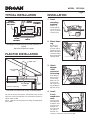
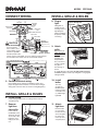
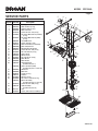
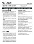
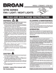
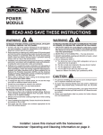
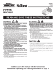
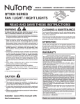
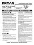
MODEL QTX110HL
Page 1
QTX SERIES
HEATER / FAN / LIGHT /
NIGHT LIGHT
READ AND SAVE THESE INSTRUCTIONS
WARNING
TO REDUCE THE RISK OF FIRE, ELECTRIC SHOCK, OR INJURY TO PERSONS, OBSERVE THE FOLLOWING:
1. Usethisunitonlyinthemannerintendedbythemanufacturer.
Ifyouhavequestions,contactthemanufacturerattheaddress
ortelephonenumberlistedinthewarranty.
2. Beforeservicingorcleaningunit,switchpoweroffatservice
panel and lock the service disconnecting means to prevent
powerfrombeingswitchedonaccidentally.Whentheservice
disconnecting means cannot be locked, securely fasten a
prominentwarningdevice,suchasatag,totheservicepanel.
3. Installation work and electrical wiring must be done by a
qualified person(s) in accordance with all applicable codes
and standards, including fire-rated construction codes and
standards.
4. Sufficientairisneededforpropercombustionandexhausting
of gases through the flue (chimney) of fuel burning equipment to prevent backdrafting. Follow the heating equipment
manufacturer’sguidelineandsafetystandardssuchasthose
publishedbytheNationalFireProtectionAssociation(NFPA),
andtheAmericanSocietyforHeating,RefrigerationandAir
ConditioningEngineers(ASHRAE),andthelocalcodeauthorities.
5. When cutting or drilling into wall or ceiling, do not damage
electricalwiringandotherhiddenutilities.
6. Ductedfansmustalwaysbeventedtotheoutdoors.
7. Provideaseparate20AMPcircuit.Use12GA.powercable
oftypewhichmeetscode.
8. Thisunitmustbegrounded.
CAUTION
1. Forgeneralventilatinguseonly.Donotusetoexhausthazardousorexplosivematerialsandvapors.
2. This product is designed for installation in ceilings up to a
12/12pitch.Ductconnectormustpointup.DONOTMOUNT
THISPRODUCTINAWALL.
3. Toavoidmotorbearingdamageandnoisyand/orunbalanced
impellers,keepdrywallspray,constructiondust,etc.offpower
unit.
4. Pleasereadspecificationlabelonproductforfurtherinformationandrequirements.
CLEANING & MAINTENANCE
Forquietandefficientoperation,longlife,andattractiveappearance-lowerorremovegrilleandvacuuminteriorofunitwiththe
dustingbrushattachment.
Themotorispermanentlylubricatedandneverneedsoiling.Ifthe
motorbearingsaremakingexcessiveorunusualnoises,replace
themotorwiththeexactservicemotor.Theimpellershouldalso
bereplaced.
Replace light bulbs with (2) 60-Watt (maximum) incandescent
lightbulbsand(1)7-Wattnightlightbulb.
OPERATION
Usea4-FunctionControltooperatetheheater,fan,light,and
nightlightseparately.See“ConnectWiring”fordetails.
NOTE:This unit is designed with a thermostat which senses
excessheatandmaystarttheblowerautomatically.Thisisnormal
andisnocauseforconcern.
NOTE:Fanmaycyclewhenlightison.Blinkinglightmayindicate
improperlampwattageortype.
WARRANTY
BROAN-NUTONE THREE YEAR LIMITED WARRANTY
Broan-NuTone warrants to the original consumer purchaser of its products that such
products will be free from defects in materials or workmanship for a period of three
years from the date of original purchase. THERE ARE NO OTHER WARRANTIES,
EXPRESS OR IMPLIED, INCLUDING, BUT NOT LIMITED TO, IMPLIED WARRANTIES
OF MERCHANTABILITY OR FITNESS FOR A PARTICULAR PURPOSE.
During this three-year period, Broan-NuTone will, at its option, repair or replace, without
charge, any product or part which is found to be defective under normal use and service.
THIS WARRANTY DOES NOT EXTEND TO FLUORESCENT LAMP STARTERS AND
TUBES. This warranty does not cover (a) normal maintenance and service or (b) any
products or parts which have been subject to misuse, negligence, accident, improper
maintenance or repair (other than by Broan-NuTone), faulty installation or installation
contrary to recommended installation instructions.
The duration of an implied warranty is limited to the three-year period as specified
for the express warranty. Some states do not allow limitation on how long an implied
warranty lasts, so the above limitation may not apply to you.
BROAN-NUTONE’S OBLIGATION TO REPAIR OR REPLACE, AT BROAN-NUTONE’S
OPTION, SHALL BE THE PURCHASER’S SOLE AND EXCLUSIVE REMEDY UNDER
THIS WARRANTY. BROAN-NUTONE SHALL NOT BE LIABLE FOR INCIDENTAL, CONSEQUENTIAL OR SPECIAL DAMAGES ARISING OUT OF OR IN CONNECTION WITH
PRODUCT USE OR PERFORMANCE. Some states do not allow the exclusion or limitation
of incidental or consequential damages, so the above limitation may not apply to you.
This warranty gives you specific legal rights, and you may also have other rights, which
vary from state to state. This warranty supersedes all prior warranties.
To qualify for warranty service, you must (a) notify Broan-NuTone at the address or
telephone number stated below, (b) give the model number and part identification and
(c) describe the nature of any defect in the product or part. At the time of requesting
warranty service, you must present evidence of the original purchase date.
Broan-NuTone LLC, 926 West State Street, Hartford, WI 53027 (1-800-637-1453)
Installer: Leave this manual with the homeowner.
MODEL QTX110HL
Page 2
TYPICAL INSTALLATION
CEILING
JOIST, TRUSS,
OR I-JOISTS
POWER
CABLES
INSTALLATION
MOUNTING
CHANNELS
1. Insert
mounting
brackets.
HOUSING
CEILING
MATERIAL
GRILLE
Housing mounted directly to joists, trusses, or
I-joists.
Up to 24-inches on-center.
Slidethe(4)
mountingbracketsintothechannelsoneachend
ofthehousing.
2. Mount housing.
PLAN THE INSTALLATION
Securehousingtoceiling
structurewith(4)
mountingscrews.
Makesurebottom
ofhousingwillbe
flushwithfinished
ceilingmaterial.
ROOFCAP*
3. Attach
damper
/ duct
connector
to housing.
6-IN.ROUND
DUCT*
*Purchaseseparately
6-IN.ROUND
ELBOW*
WALL
CAP*
Unit shown connected to 6-inch round ductwork.
The unit will operate most quietly and efficiently when located
wherethe shortest possible duct run and minimum numberof
elbowswillbeneeded.
Plantosupplytheunitwithproperlinevoltageandappropriate
powercable.
Snapdamper/
ductconnector
ontohousing.
Makesureconnectorisflush
withtopofhousinganddamper
flapfallsclosed.
4. Install
6-inch
round ductwork.
Connect6-inch
roundductwork
todamper/duct
connector.Run
ductworktoa
roofcaporwall
cap.Tapeall
ductworkconnectionstomakethemsecureandairtight.
MODEL QTX110HL
Page 3
CONNECT WIRING
HEAT
&
NIGHT LIGHT
INSTALL GRILLE & BULBS
8. Plug-in
light.
LIGHT
&
FAN
VENTILATOR
HOUSING
RED to BLACK
(Heat)
BLACK to YELLOW
(Night Light)
RED to RED
(Fan)
BLACK to BLUE
(Light)
WHITE to WHITE
WHITE to WHITE with red stripe
WIRING PLATE
FROM VENTILATOR
GROUND
BLACK to RED
BLACK to BLUE
WHITE
to
WHITE
CAUTION
RED
LIGHT (red)
NIGHT LIGHT (blue)
(3-position rocker)
FAN (2-position rocker)
RATING SPECIFICATIONS
GREEN
HEAT (2-position rocker)
The three-position
RED
rocker switch is rated
Broan 4-Function
5 A @ 125VAC. Use this
4-FUNCTION
CONTROL
Control shown
120 VAC LINE IN
switch for Lights ONLY.
(purchase separately)
BLACK to BLACKS
Each two-position rocker
switch is rated 15 A @ 120VAC. Use these switches for Heat and Vent.
The total load on this control must not exceed 20 A @ 120VAC.
5. Connect electrical wiring.
Run120VAChousewiringtoinstallationlocation.Use
properULapprovedconnectorstosecurehousewiringto
wiringplate.Connectwiresasshowninwiringdiagram(s).
9. Attach
grille.
Removethe(2)
grille mounting
screwsfrom
thesidesofthe
housing.(See
Step8illustration.)Usethese
screwstoattach
thegrilleto
thehousingas
shown.
Toavoiddamagetothegrille:DONOTOVERTIGHTEN
SCREWS.Tightenscrewsonlyuntilgrilleissnugagainst
ceilingmaterial.
10. Install
bulbs.
INSTALL GRILLE & BULBS
6. Finish ceiling.
Theunit
accepts(2)
60-Watt(maximum)incandescentbulbsand
(1)7-Wattnight
lightbulb.
Installceilingmaterial.Cutoutceilingmaterialclosely
aroundhousing.
7. Remove
light lens
from grille.
Holdgrilleassemblyupnear
housing.Connect
lightplugfrom
grilleassemblyto
receptacleinside
ofhousing.
Insertasmall
flat-bladedscrewdriverintotheslot
atoneendofthe
lightlens.Carefullyprythelens
out.
GRILLEMOUNTING
SCREWS
11. Attach
light lens.
Hookthetabs
ononeendof
thelensintothe
slotinthegrille.
Liftotherend
oflensupand
snapintoplace.
MODEL QTX110HL
Page 4
SERVICE PARTS
Key No.
Part No.
1
2
3
4
5
6
7
8
9
10
11
12
13
14
15
16
17
18
19
20
21
22
23
24
25
26
27
28
29
30
97016470
98007763
98003036
97016450
99170245
93260454
99260512
98010091
99150471
97016563
98010090
98010089
99150415
99260488
97016564
99020283
99260423
98010088
99080558
97016565
97016566
99020284
99080556
99100491
97016471
99250959
99260558
97016567
93150459
97016474
99111291
99150622
Description
Housing
SlideChannel(2req.)
SupportAngle(4req.)
DuctConnector
Screw#8-18X.375(8req.)
Nut,SheetMetal#8-18(Partition)
(2req.)
Nut,SheetMetal#8-18(Grille)
(3req.)
Cover/KOPanel
Screw,Ground(2req.)
WirePanel/HarnessAssembly
WireCompartment
MountingBracket-Heater
Screw#8-18X.250(4req.)
Nut,Hex#10-24(5req.)
HeaterScroll
Wheel-Heater
Nut,Hex#8-32(4req.)
MotorMount
Motor-Heater
HeatingElement
(includesKeyNo.7)
HeaterScrollAssembly
(includesKeyNos.12thru20)
Wheel-Fan
Motor-Fan
Isolator(4req.)
Partition
Washer(4req.)
Nut,HexLock#8-32(4req.)
BlowerAssembly
(includesKeyNos.21thru26)
Screw#8-18X.500(2req.)
GrilleAssembly
(includesKeyNo.29)
Lens
Screw,Grille#8-18X2.000(2req.)
8
5
2
3
9
1
7
3
4
6
5
7
14
2
19
13
20
11
10
7
5
18
5
12
13
17
16
15
14
21
22
23
24
25
27
26
28
30
29
99043413H