1
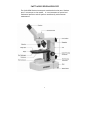
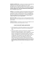
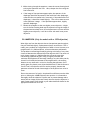
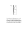
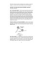
SWIFT M3500 SERIES MICROSCOPE
The Swift M3500 Series microscope is considered to be the most “Student
proof” microscope on the market. It is an instrument of optical and
mechanical precision and will perform satisfactorily with minimum
maintenance.
1
MICROSCOPE COMPONENTS
ARM - the vertical column (attached to the base) which supports the
stage and contains the coarse and fine adjusting knobs and focusing
mechanism.
BASE - the housing and platform of the instrument to which the arm is
attached. The base stands on rubber feet and contains the illuminator
assembly. The bulb replacement part number is printed on the underside
of the base.
COARSE FOCUS CONTROL MECHANISM - this model is a stage focusing
model meaning the stage moves up or down by means of a brass rack and
steel pinion gear to bring the specimen into focus. The movement is
achieved by two large knobs on the sides of the arm. In order to prevent
gear damage, the focus control is equipped with a slip clutch that allows
slippage at both ends of the focusing range. The system is also furnished
with a tension control to prevent “stage drift”.
CONDENSER – the condenser is mounted in the stage and it is used in
conjunction with the iris diaphragm. The function of the condenser is to
provide full illumination to the specimen plane and to enhance the
resolution and contrast of the object being viewed.
CORD HOLDERS - A pair of half-circle brackets installed on the back of
the arm which are used to store the electrical cord.
DISC DIAPHRAGM - The wheel-shaped disc attached to the underside of
the stage. It has circular openings, called apertures, and may be rotated
to align any of the apertures with the optical path.
EYEPIECES - the upper optical element that further magnifies the
primary image of the specimen and brings the light rays in focus at the
eyepoint. The eyepiece has a calibrated POINTMASTER® scale for taking
measurements.
FIELD CONDENSER - A lens located in the light housing which intensifies
the light from the illuminator in the base.
FINE FOCUS CONTROL MECHANISM - the fine focusing knobs, located on
either side of the microscope, in front of and slightly lower than the
2
coarse focusing knobs, are used for precise focusing adjustments once
the specimen has been brought into view with the coarse focus controls
HEAD - it is the top portion of the microscope that contains the
refracting prisms and the eyepiece tube. The eyepiece is locked onto the
eyepiece tube with a set screw. The head rotates allowing operation of
the microscope from the front or the back, and allows the microscope to
be shared by simply rotating the head.
IRIS DIAPHRAGM - a round multi-leaf device mounted below the
condenser which is controlled by a lever. It is similar to a camera shutter
and controls the amount of light entering the condenser, allowing the
user to control contrast. If the image is “washed out” the iris diaphragm
is opened too wide. If the image is too dark the iris is not open wide
enough.
MECHANICAL STAGE - An alternative to stage clips is a Mechanical Stage.
A Mechanical Stage holds the slide in place, allowing the user to move
the slide on any x/y axis through the manipulation of two control knobs
or a co-axial control mechanism.
NOSEPIECE - the revolving turret that holds the objective lenses,
permitting changes in magnification by rotating different powered
objective lenses into the optical path. The nosepiece must “click” into
place for the objectives to be in proper alignment.
OBJECTIVES - The DIN objectives are standard in the industry, with large
numerical aperture (N.A.) to permit maximum resolution. All objectives
are achromatic, color-coded and parfocaled at a 45mm distance. The
40XRD and the 100XRD are sealed to keep oil residue from seeping into
the objective. These two objectives have a spring loaded tip to prevent
accidental breakage of either the slide or front lens of the objective if
they should come into contact with each other.
Part No. Mag.
MA10071F 4X
MA10072 10X
MA10073S 40X
MA10074 100X
N.A. Working Distance
0.10
14.83mm
0.25
6.32mm
0.65
0.53mm
1.25
0.23mm
Field of View Color Code
4.50mm
Red
1.80mm
Yellow
0.45mm
Blue
0.18mm
White
POWER SWITCH - turns the illuminator on and off.
3
STAGE - the table of the microscope where the slide is placed for viewing.
This component moves upward and downward when the focusing knobs
are turned.
STAGE CLIPS - A pair of flexible metal clips attached by spring screws
that hold the slide in position on the stage.
IMPORTANT MICROSCOPY TERMS
APERTURE, ANGULAR - The angle (or cone) of light rays capable of
entering the front lens of the objective from a point in the object. By
increasing the angular aperture of an objective, more light rays from the
specimen can be taken in by the lens; hence the resolving power is
increased.
COMPOUND MICROSCOPE - a microscope having a primary magnifier (the
objective) and a second (the eyepiece) to both conduct light, amplify
magnification and convert the image into a field of view easily seen by
the human eye.
COVER GLASS - Thin glass cut in circles, rectangles or squares, for
covering the specimen, usually a thickness of 0.15 to 0. I7mm. The
majority of specimens should be protected by a cover glass, and must be
covered when using 40XRD or 100XRD objectives.
DEPTH OF FOCUS - The ability of a lens to furnish a distinct image above
and below the focal plane. Depth of focus decreases with the increase of
numerical aperture or with the increase of magnification.
DIN – (Deutsche Industrial Norman) An international optical standard for
the manufacturing of most quality microscope lenses. Many DIN lenses
will be interchangeable from one DIN microscope to another.
FIELD OF VIEW - the area of the object that is seen when the image is
observed. It may range in diameter from several millimeters to less than
0.1mm.
FOCAL LENGTH - parallel rays of light after refraction through a lens will
converge to a focus at the focal point. The distance from the optical
center of the lens to the focal point is the focal length.
4
NUMERICAL APERTURE (NA) – a measure of an objective’s light gathering
capabilities. The concept may be compared to the F-valve in
photographic lenses. Generally speaking, objectives with N.A. values of
less than 1.00 are "Dry" objectives. Values of 1.00 or greater require oil as
a medium. Please note that condensers are part of the optical system and
are also assigned an N.A. value. That value must be at least as high as
that of the highest objective used.
PARFOCAL - A term applied to objectives and eyepieces when practically
no change in focus has to be made when an objective of one power is
substituted for another. The DIN objectives on your Swift M3500 Series
Microscope are parfocaled at the factory to a standard 45mm distance,
so that only a slight turn of the f ine adjustment is required when a
change is made from a lower to higher power.
RESOLVING POWER - The ability of a lens to clearly separate fine detail.
Resolving power is directly proportional to the numerical aperture of the
optical system.
WORKING DISTANCE – the distance from the lens of the objective to the
cover slip on the slide, when the specimen is in focus.
USING YOUR SWIFT M3500 MICROSCOPE
1. Use the stage clips or slide holder mechanism to secure the slide in
place. Be sure the specimen is centered over the opening in the
stage.
2. Rotate the nosepiece to place the lowest power (4X) objective over
the specimen. Be sure the objective “clicks” into position.
The disc or iris diaphragm should be turned or adjusted to the largest
aperture, allowing the built-in substage illuminator to provide a
constant, even dispersion of light to the optical system. The disc or
iris diaphragm is not intended to control the brightness of the
illumination. The purpose of the diaphragm is to match the
numerical aperture of the objective. Smaller apertures increase
contrast in the image while large apertures decrease the contrast. A
good procedure in selecting the proper aperture is to start with the
largest and reduce until the fine detail of the specimen is in exact
focus.
5
3. While viewing through the eyepiece, rotate the coarse focusing knob
to bring the specimen into view. Next, sharpen the focus using the
fine focus knob.
4. If the image of the specimen appears pale, the aperture of the
diaphragm should be decreased (if the model has a disc diaphragm,
rotate the disc to a smaller hole, conversely, if the model has the iris
diaphragm, it should be closed slightly). This will increase contrast
in the specimen’s image. If the specimen appears dark, slightly
open the diaphragm.
5. Rotate the nosepiece to the next higher power objective. A slight
turn of the fine focusing knob may be required to bring the image of
the specimen into sharp focus. Once the specimen is in focus with the
highest power objective, it will be in focus with each lower power
objective.
OIL IMMERSION (Only for models with a 100X objective)
When light rays from the objective lens to the specimen pass through air,
they are distorted slightly, a phenomenon known as refraction. This is
usually not a problem at a magnification of 400X or lower. However, at a
magnification of 1,000X and above, refraction becomes problematic.
This problem is reduced significantly by placing a thin layer of very clear,
viscous oil between the slide and tip of the objective lens. The result is a
much clearer image at 1,000X because the oil has the same light
transmitting properties as glass. Using oil slightly increases the
resolution and brightness of the image. Usually a very thin slide (size #1)
is used for oil immersion because at this magnification, the working
distance is very small and is critical to focusing the specimen. Good
quality glass (not plastic) cover slips should be used. If their thickness is
over 0.17mm, the objective will not resolve properly, because the
specimen cannot be moved close enough to the objective lens to be in
focus.
Place a tiny amount of oil (only 1 drop should be sufficient) onto the slide
prior to rotating the 100XRD objective into position. It is essential to
thoroughly clean the objective tip after use to prevent damage and to
ensure that an image can be seen clearly the next time the objective is
used. Please contact Swift Optical or your authorized Swift dealer for the
appropriate immersion oil to use.
6
IMPORTANT: The working distances of the 40XRD and 100XRD objectives
to the slide surface are very small and although the oil immersion
objectives are sealed to prevent oil contamination, it is a good practice
to avoid dragging these objectives through an oiled slide. The 100XRD oil
immersion lens on Swift microscopes has a spring-loaded end to prevent
cracking the cover slip upon its initial contact. Once this zone of safety is
exceeded by moving the slide further toward the lens, a point can be
reached where damage will occur. Always make a practice of frequently
checking the position of the lens on the slide. Note that a 100XRD
objective requires an iris diaphragm for brightfield oil immersion
microscopy.
HOW TO USE THE POINTMASTER® EYEPIECE RETICLE
Swift's patented POINTMASTER® eyepiece reticle, which is installed in
the eyepiece of the M3500 microscope, enables the user to easily
measure the size of the specimen.
I. The numbers on the chart indicate the actual size of the
POINTMASTER® scale in millimeters. For example, the length is
1.0mm from the top of the arrow to the bottom; the total length of
the scale is 8.0mm, etc. The thickness of all the horizontal lines is
0.01mm.
2. To obtain the actual physical size of a specimen, divide the
POINTMASTER® scale readings by the magnification of the objective
lens that is in use. Divide the readings by 10 if the 10X objective is
being used, 40 if the 40XRD objective is in use, or 100 if of 100XRD is
in use.
7
DIGITAL PHOTOGRAPHY
The M3501CL-DGL and M3503CL-4DGL models feature a built-in 1280 X
1024 pixel digital camera to capture still images or video clips on to a
computer. In order to use the camera, the software must first be
installed on a computer. The minimum computer requirements to use
the camera is having an available USB 2.0 port, Windows XP, Vista or Mac
OS X operating system installed on the computer, 512MB of RAM, 1GB free
hard drive space and 1Ghz CPU. Instructions on how to install and use
the software is included on the software CD that was packaged with
the M3501CL-DGL and M3503CL-4DGL microscopes.
8
PARTS AND ACCESSORIES
EYEPIECE REPLACEMENTS
MA10510
W10XD, 18mm Eyepiece
MA10511
W10XD, 18mm Eyepiece with Pointmaster
OBJECTIVE
MA10071F
MA10072
MA10073S
MA10074
REPLACEMENTS
4XD Achromat Objective
10XD Achromat Objective
40XRD Achromat Objective
100XRD Achromat Objective
MISC. ACCESSORIES
MA268
Stage Clips (pair)
MA533
Dust Cover
MA12005 High-drive Mechanical Stage
MA12006 Low-drive co-axial Mechanical Stage
MA15383 Cord Holder (pair)
MA2202F 5W Fluorescent Bulb
MA2215
.06 W LED replacement lamp
CARE AND CLEANING
The M3500 Series microscope is designed to function with minimal
maintenance, but certain components should be cleaned frequently to
ensure ease of viewing. The power switch should also be turned off or
unplugged when the microscope is not in use.
CLEANING – The front lens of the objectives (particularly the 40XRD and
100XRD should be cleaned after use. First brush with a soft, camel hair
brush or blown off with clean, oil free air to remove dust particles. Then
wipe gently with a soft lens tissue, moistened with optical cleaner
(eyeglass or camera lens) or clean water. Immediately dry with a clean
lens paper.
CAUTION - Objectives should never be disassembled by the user. If
repairs or internal cleaning should be necessary, this should only be done
by qualified, authorized microscope technician. The eyepiece(s) may be
cleaned in the same manner as the objectives, except in most cases
optical cleaner will not be required. In most instances breathing on the
eyepiece to moisten the lens and wiping dry with a clean lens tissue is
sufficient to clean the surface. Lenses should never be wiped while dry
as this will scratch or otherwise mar the surface of the glass.
9
The finish of the microscope is hard epoxy and is resistant to acids and
reagents. Clean this surface with a damp cloth and mild detergent.
Periodically, the microscope should be disassembled, cleaned and
lubricated. This should only be done by a qualified, authorized
microscope technician.
DUST COVER AND STORAGE – All microscopes should be protected from
dust by a dust cover when in storage or not in use. A dust cover is the
most cost-effective microscope insurance you can buy. Ensure that the
storage space is tall enough to allow the microscope to be placed into
the cabinet or onto a shelf without making undue contact with the
eyepieces. Never store microscopes in cabinets containing chemicals
which may corrode your microscope. Also, be sure that the objectives
are placed in the lowest possible position and the rotating head is turned
inward and not protruding from the base. Microscopes with mechanical
stages should be adjusted toward the center of the stage to prevent the
moveable arms of the mechanical stage from being damaged during
storage in the cabinet.
TENSION CONTROL OF FOCUSING MOVEMENT - Tension of the focusing
movement is controlled by a tension system found on the pinion metal of
the rapid focus control. This can be adjusted by using the Swift part
#MT205 wrench.
BULB REPLACEMENT - To prolong the life of the bulb you should always
turn off the unit when not in use. The replacement bulb part number can
be found underneath the microscope on the metal base plate. The
M3500DF models use a 5W fluorescent bulb Swift part number MA2202F.
The M3500CL models use a .06W LED Swift part number MA2215.
10
MA2202F Fluorescent Bulb
To replace a bulb, you must first turn the power off and unplug the
microscope’s electrical cord from the electrical socket and remove
any slides on the stage. Carefully turn the microscope on its side,
unscrew and open the hinged cover. A cable tie is used to secure the bulb
to the bulb socket and must be cut and removed. Make sure the bulb is
cool and remove it by carefully pulling the bulb out of its socket. Insert
the new bulb by seating the bulb firmly into the socket. The bulb should
not need further alignment. Another small cable tie can be used to
secure the bulb to the socket if the microscope is going to be moved
around often. Close the hinged cover and tighten the screw to hold the
hinged cover closed.
MA2215 LED
To replace an LED, you must first turn the power off and unplug the
microscope’s electrical cord from the electrical socket and remove any
slides on the stage. Use the small allen wrench (.09mm) that was
included with the microscope to loosen the set screws that hold the
black illuminator housing onto the base of the microscope. Remove the
illuminator housing to expose the LED. Simply pull the LED straight up to
remove it from the light socket. Align the 2 metal socket pins with the
holes at the bottom of the new LED and push the LED onto the socket.
Re-install the illuminator housing.
COMMON PROBLEMS IN MICROSCOPY
CAUTION – Never disassemble mechanical or optical components. This
servicing should only be done by an authorized Swift technician. The
Limited Lifetime Warranty will be null and void if the mechanical or
optical components are disassembled by a non-Swift dealer.
A.
PROBLEM – No Illumination
CORRECTION 1. Is the power plug connected to an active A.C. outlet?
2. Is the on/off power switch working properly?
3. Check the bulb. Try a new bulb if you have one.
4. Check the contact points of the bulb and socket
11
B. PROBLEM – Illumination “hot spots” and uneven brightness in the
field of view.
CORRECTION 1. Is the Abbe condenser in the correct position?
2. Are the nosepiece and objective clicked into proper position?
C.
PROBLEM – Image appears “washed out” or weak.
CORRECTION 1. Slightly close the diaphragm to a smaller aperture
2. Objective lens is dirty. See “Care and Cleaning” Section.
3. Eyepiece is dirty. See “Care and Cleaning” Section.
D.
PROBLEM – Dust or hairs seem to be moving in the image.
CORRECTION – The iris diaphragm is not open wide enough. Slowly
open the diaphragm to increase the size of the opening allowing
for additional illumination.
E. PROBLEM - Once the specimen is in focus, it moves out of focus
CORRECTION – Gravity is causing the stage to drift downward,
causing loss of focus. The focusing tension should be increased to act as a
brake to prevent this downward drift. The M3500 Series is outfitted with
a tension collar on the focusing shaft to allow tension to be increased or
decreased on the Swift slip-clutch system. See page 10.
F.
PROBLEM – Focusing knobs turn with difficulty.
CORRECTION –
1. Loosen the tension collar adjustment. See page 9.
2. The microscope should be disassembled, cleaned and
re-lubricated by a qualified, authorized technician.
12


![[January] [2010] Oracle Part Number E51573-01](http://vs1.manualzilla.com/store/data/005777075_1-9f1c819619cc4ae74609e937019c49fd-150x150.png)