1
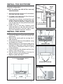
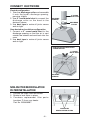
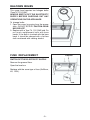
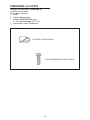
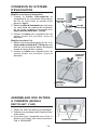
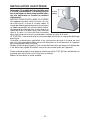
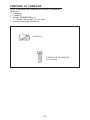
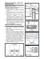
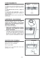
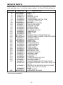
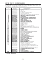
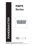
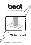
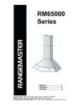
RMP1
Series
ENGLISH......................................3
FRANÇAIS.................................11
ESPAÑOL...................................19
Broan-NuTone LLC. 926 West State Street, Hartford, WI 53027
NuTone, Inc., 4820 Red Bank Road, Cincinnati, OH 45227
Broan-NuTone Canada, INC.1140 Tristar Drive, Mississauga, Ontario, L5T 1H9
-2-
READ AND SAVE THESE INSTRUCTIONS
WARNING
WARNING
SUITABLE FOR USE IN HOUSEHOLD
COOKING AREA.
TO REDUCE THE RISK OF INJURY TO PERSONS IN THE EVENT OF A RANGE TOP
GREASE FIRE, OBSERVE THE FOLLOWING:*
1. SMOTHER FLAMES with a close-fitting lid,
cookie sheet, or metal tray, then turn off the
burner. BE CAREFUL TO PREVENT BURNS.
If the flames do not go out immediately, EVACUATE AND CALL THE FIRE DEPARTMENT.
2. NEVER PICK UP A FLAMING PAN - You may
be burned.
3. DO NOT USE WATER, including wet dishcloths
or towels - violent steam explosion will result.
4. Use an extinguisher ONLY if:
A. You know you have a Class ABC extinguisher and you already know how to operate it.
B. The fire is small and contained in the area
where it started.
C. The fire department is being called.
D. You can fight the fire with your back to an
exit.
* Based on “Kitchen Fire Safety Tips” published by NFPA.
TO REDUCE THE RISK OF FIRE, ELECTRICAL
SHOCK, OR INJURY TO PERSONS, OBSERVE
THE FOLLOWING:
1. Use this unit only in the manner intended by
the manufacturer. If you have questions, contact the manufacturer at the address or telephone number listed in the warranty.
2. Before servicing or cleaning unit, switch power
off at service panel and lock service panel to
prevent power from being switched on
accidentally. When the service disconnecting
means cannot be locked, securely fasten a
prominent warning device, such as a tag, to
the service panel.
3. Installation work and electrical wiring must be
done by a qualified person(s) in accordance
with all applicable codes and standards, including fire-rated construction codes and standards.
4. Sufficient air is needed for proper combustion
and exhausting of gases through the flue (chimney) of fuel burning equipment to prevent
backdrafting. Follow the heating equipment
manufacturer’s guidelines and safety standards such as those published by the National
Fire Protection Association (NFPA), and the
American Society for Heating, Refrigeration
and Air Conditioning Engineers (ASHRAE), and
the local code authorities.
5. When cutting or drilling into wall or ceiling, do
not damage electrical wiring and other hidden
utilities.
6. Ducted fans must always be vented to the outdoors.
7. Do not use this unit with any solid-state speed
control device.
8. To reduce the risk of fire, use only steel
ductwork.
9. This unit must be grounded.
TO REDUCE THE RISK OF A RANGE TOP
GREASE FIRE:
A. Never leave surface units unattended at high settings.
Boilovers cause smoking and greasy spillovers that
may ignite. Heat oils slowly on low or medium settings.
B. Always turn hood ON when cooking at high heat or
when cooking flaming foods.
C. Clean ventilating fans frequently. Grease should not
be allowed to accumulate on fan or filter.
D. Use proper pan size. Always use cookware appropriate
for the size of the surface element.
CAUTION
1. To reduce risk of fire and to properly exhaust air,
be sure to duct air outside. Do not vent exhaust
air into spaces within walls or ceilings or into
attics, crawl spaces, or garages.
2. Take care when using cleaning agents or
detergents.
3. Avoid using food products that produce flames
under the Range Hood.
4. For general ventilating use only. Do not use to
exhaust hazardous or explosive materials and
vapors.
5. To avoid motor bearing damage and noisy and/
or unbalanced impellers, keep drywall spray,
construction dust, etc. off power unit.
6. Your hood motor has a thermal overload which
will automatically shut off the motor if it becomes
overheated. The motor will restart when it cools
down. If the motor continues to shut off and
restart, have the hood serviced.
7. For best capture of cooking impurities, the
bottom of the hood should be a minimum of 24"
and a maximum of 30" above the cooking surface.
8. Two installers are recommended because of the
large size and weight of this hood.
9. Please read specification label on product for
further information and requirements.
-3-
PREPARE THE HOOD
Unpack hood and check contents.
You should receive:
1 - Hood
1 - Discharge Collar
1 - Parts Bag (B080810168) containing:
4 - Mounting Screws (3,2 x 13mm)
1 - Installation Instructions
DISCHARGE COLLAR
4 MOUNTING SCREWS (3,2 x 13mm)
-4-
INSTALL THE DUCTWORK
ROOF CAP
ROUND
DUCT
Ducted configuration
NOTE: To reduce the risk of fire, use only
metal ductwork.
1. Decide where the ductwork will run between
the hood and the outside.
2. A straight, short duct run will allow the hood
to perform most efficiently.
3. Long duct runs, elbows, and transitions will
reduce the performance of the hood. Use
as few of them as possible. Larger ducting
may be required for best performance with
longer duct runs.
4. Install a roof or wall cap. Connect round
metal ductwork to cap and work back towards hood location. Use duct tape to seal
the joints between ductwork sections.
WALL
CAP
HOOD
6”
ROUND
ELBOW
24” TO 30” ABOVE
COOKING SURFACE
METAL GRILLE
INSTALL THE HOOD
1. Remove the grease filters by pushing filter
towards the back of hood and rotating filter
downward.
2. Remove the metal grille by moving the 2
side fasteners.
3. Cut a hole in the bottom of the cabinet, using
the dimensions shown.
4. Adjust the position of the clasping side spring
by means of the proper screw, according to
the thickness of the panel to which it is going
to be anchored.
5. Insert the hood in the cabinet and lock it by
means of the side spring.
6. Use the holes in the casing of the hood to
attach it using 4 mounting screws.
7. Replace grille and filters.
GREASE FILTERS
CUT A HOLE IN THE BOTTOM OF
THE CABINET
MOUNTING SCREWS
CLASPING
SIDE SPRING
10-1/4”
26-5/8”
min 7-16”
max 13/16”
-5-
CONNECT DUCTWORK
DUCTED CONFIGURATION
Ducted configuration
1. Take the discharge collar and assemble
it onto the hood’s discharge opening,
pressing slightly.
2. Use 6" round metal duct to connect the
discharge collar on the hood to the
ductwork above.
3. Use duct tape to make all joints secure
and air tight.
6” ROUND
METAL DUCT
DISCHARGE
OPENING
DISCHARGE
COLLAR
Non-ducted recirculation configuration
1. Connect a 6” round metal duct to the
discharge opening so that the air is sent
outside the cabinet and sent back into the
room.
2. Use duct tape to make all joints secure
and air tight.
NON-DUCTED RECIRCULATION
CONFIGURATION
6” ROUND
METAL DUCT
DISCHARGE
OPENING
NON-DUCTED RECIRCULATION
FILTER INSTALLATION
1. Position the filters over the blower.
2. Rotate to lock filters in place.
3. Purchase replacement filter packs
(contains 2) from your dealer.
Part No. B03300487.
NON-DUCTED
RECIRCULATION FILTERS
-6-
WIRING
Note: This range hood must be properly
33-7/16”
grounded. The unit should be installed by a
(85cm)
qualified electrician in accordance with all
applicable national and local electrical
codes.
GROUNDING INSTRUCTIONS
This appliance must be grounded. In the event
of an electrical short circuit, grounding
reduces the risk of electric shock by providing
an escape wire for the electric current. This
appliance is equipped with a cord having a
grounding wire with a grounding plug. The
plug must be plugged into an outlet that is
properly installed and grounded.
WARNING - Improper grounding can result in a risk of electric shock.
Consult a qualified electrician if the grounding instructions are not completely
understood, or if doubt exists as to whether the appliance is properly grounded.
Do not use an extension cord. If the power supply cord is too short, have a qualified
electrician install an outlet near the appliance.
Position the electrical outlet at a maximum distance of 33-7/16” (85 cm) from
where the lead exits from the hood (see illustration alongside).
Fit the plug into the outlet.
-7-
MAINTENANCE
Proper maintenance of the Range Hood will
assure proper performance of the unit.
Grease Filters
The grease filters should be cleaned frequently. Use a warm detergent solution. Grease
filters are dishwasher safe.
Remove filter by pushing filter towards the back
of hood and rotating filter downward.
GREASE FILTERS
Non-ducted recirculation Filters
The charcoal filters should be changed every
6 months. Rotate the filters to remove and
replace.
Hood Cleaning
Stainless steel is one of the easiest materials
to keep clean. Occasional care will help preNON-DUCTED
serve its fine appearance.
RECIRCULATION
FILTERS
Cleaning tips:
• Hot water with soap or detergent is all that is
usually needed.
• Follow all cleaning by rinsing with clear water. Wipe dry with a clean, soft cloth to
avoid water marks.
• For discolorations or deposits that persist, use a non-scratching household cleanser
or stainless steel polishing powder with a little water and a soft cloth.
• For stubborn cases, use a plastic scouring pad or soft bristle brush together with
cleanser and water. Rub lightly in direction of polishing lines or "grain" of the
stainless finish. Avoid using too much pressure which may mar the surface.
• DO NOT allow deposits to remain for long periods of time.
• DO NOT use ordinary steel wool or steel brushes. Small bits of steel may adhere
to the surface causing rust.
• DO NOT allow salt solutions, disinfectants, bleaches, or cleaning compounds to
remain in contact with stainless steel for extended periods. Many of these compounds contain chemicals which may be harmful. Rinse with water after exposure and wipe dry with a clean cloth.
Painted surfaces should be cleaned with warm water and mild detergent only.
OPERATION
Controls
The hood is operated using the slide controls
under the bottom of the hood.
LIGHT
SWITCH
BLOWER
SWITCH
The light switch turns the lamps on and off.
The blower switch :makes it possible to select
the motor operating speed. Position 0: motor
off.
The pilot lamp lights up whenever the blower
is on.
-8-
PILOT LAMP
HALOGEN BULBS
This range hood requires two halogen bulbs
(Type T4, 12V, 20W).
ALWAYS SWITCH OFF THE ELECTRICITY
SUPPLY BEFORE CARRYING OUT ANY
OPERATIONS ON THE APPLIANCE.
To change bulbs:
1. Open the cover by prying from the proper
slots. - DO NOT ROTATE. CAUTION: BULB
MAY BE HOT!
3. Replace with a Type T4, 12V, 20W bulb. Do
not touch replacement bulb with bare
hands! If the bulb is touched with the bare
hand, it should be cleaned with a lint-free
cloth moistened with rubbing alcohol.
FUSE REPLACEMENT
FUSE BOX
SWITCH OFF THE ELECTRICITY SUPPLY.
Remove the grease filters.
Open the fuse box.
Replace with the same type of fuse (5x20mm,
4A, 125V).
FUSE
-9-
WARRANTY
BROAN-NUTONE LLC ONE YEAR LIMITED WARRANTY
Broan-NuTone LLC warrants to the original consumer purchaser of its products that such products will be free from defects
in materials or workmanship for a period of one year from the date of original purchase. THERE ARE NO OTHER WARRANTIES, EXPRESS OR IMPLIED, INCLUDING, BUT NOT LIMITED TO, IMPLIED WARRANTIES OR MERCHANT
ABILITY OR FITNESS FOR A PARTICULAR PURPOSE.
During this one-year period, Broan-NuTone LLC will, at its option, repair or replace, without charge, any product or part which
is found to be defective under normal use and service.
THIS WARRANTY DOES NOT EXTEND TO FLUORESCENT LAMP STARTERS, TUBES, HALOGEN AND
INCANDESCENDT BULBS. This warranty does not cover (a) normal maintenance and service or (b) any products or parts
which have been subject to misuse, negligence, accident, improper maintenance or repair (other than by Broan-NuTone LLC),
faulty installation or installation contrary to recommended installation instructions.
The duration of any implied warranty is limited to the one-year period as specified for the express warranty. Some states do
not allow limitation on how long an implied warranty lasts, so the above limitation may not apply to you.
BROAN-NUTONE LLC’S OBLIGATION TO REPAIR OR REPLACE, AT BROAN-NUTONE LLC’S OPTION, SHALL BE
THE PURCHASER’S SOLE AND EXCLUSIVE REMEDY UNDER THIS WARRANTY. BROAN-NUTONE LLC SHALL
NOT BE LIABLE FOR INCIDENTAL, CONSEQUENTIAL OR SPECIAL DAMAGES ARISING OUT OF OR IN CONNECTION WITH PRODUCT USE OR PERFORMANCE. Some states do not allow the exclusion or limitation of incidental or
consequential damages, so the above limitation or exclusion may not apply to you.
This warranty gives you specific legal rights, and you may also have other rights, which vary from state to state. This warranty
supersedes all prior warranties.
To qualify for warranty service, you must (a) notify Broan-NuTone LLC at the address stated below or telephone: 1-800-6371453, (b) give the model number and part identification and (c) describe the nature of any defect in the product or part. At the
time of requesting warranty service, you must present evidence of the original purchase date.
Broan-NuTone LLC. 926 West State Street, Hartford, WI 53027 (1-800-637-1453)
NuTone, Inc., 4820 Red Bank Road, Cincinnati, OH 45227 (1-800-543-8687)
Broan-NuTone Canada, Inc. 1140 Tristar Drive, Mississauga, Ontario, L5T 1H9 (1-888-882-7626)
- 10 -
LISEZ ET CONSERVEZ CES INSTRUCTIONS
AVERTISSEMENTS
AVERTISSEMENTS
PEUT ÊTRE UTILISÉ DANS LES ZONES CUISSON DES
CUISINES FAMILIALES.
POUR REDUIRE LES RISQUES DE DOMMAGES AUX
PERSONNES AU CAS OÙ VOTRE CUISI-NIERE
PRENDRAIT FEU, OBSERVEZ LES INSTRUCTIONS
SUIVANTES:*
1. ETEINDRE LES FLAMMES à l’aide d’un couvercle le
plus hermétique possible, une plaque à gâteaux, ou un
plateau en métal, puis éteindre le brûleur. ATTENTION
à NE PAS VOUS BRÛLER. Si les flammes ne s’éteignent
pas immédiatement, SORTEZ ET APPELEZ LES
POMPIERS.
2. NE PRENEZ JAMAIS EN MAIN UNE POÊLE OU UNE
CASSEROLE QUI A PRIS FEU - Vous pourriez vous
brûler.
3. N’UTILISEZ PAS D’EAU, ni torchons ou serviettes
mouillés - vous provoqueriez une violente explosion de
vapeur.
4. Utilisez un extincteur SEULEMENT si:
A. Vous savez que vous avez un extincteur Classe
ABC, et vous en connaissez déjà le mode d’emploi.
B. Ce n’est pas un très gros incendie et qu’il se limite
à l’endroi où il a explosé.
C. Vous êtes en train d’avertir les pompiers.
D. Vous avez la possibilité d’essayer d’éteindre l’incendie
en ayant le dos tourné vers une issue.
* D’après les “Suggestions concernant la Sécurité contre
les incendies des cuisines” publiées par NFPA.
POUR REDUIRE LES RISQUES D’INCENDIE, DE
DECHARGES ELECTRIQUES OU DE DOMMA-GES AUX
PERSONNES, OBSERVEZ LES IN-STRUCTIONS
SUIVANTES:
1. N’utilisez cet appareil que comme cela est indiqué par le
constructeur. Si vous avez des problèmes, contactez le
fabriquant à l’adresse ou au numéro de téléphone
indiqués dans la garantie.
2. Avant de pourvoir à l’entretien ou au nettoyage de votre
appareil, éteignez-le au tableau des commandes ou
bloquez le tableau des commandes afin d’éviter de le
mettre en marche accidentellement. Si vous ne pouvez
pas bloquer le système permettant d’éteindre votre
appareil, appliquez un avertissement extérieur d’une
façon sure, comme par exemple un panneau, sur le
tableau des commandes.
3. L’assemblage et la connexion électrique doivent être faits
par des personnes qualifiées en respectant les normes
et règlements en vigueur, y compris les normes et
règlements concernant les possibilités d’incendie.
4. Il est indispensable qu’il y ait suffisamment d’air pour que
la combustion et l’évacuation des gaz à travers le tuyau
du brûleur du combustible ait lieu sans retour de flamme.
Suivez les indications données par le fabricant du brûleur
ainsi que les normes de sécurité comme celles qui sont
publiées par l’Association Nationale pour la Protection
contre les Incendies National Fire Protection Association
(NFPA) et la American Society for Heating, Refrigeration
and Air Conditioning Engineers (ASHRAE), et les autorités
locales en matière de normes.
5. Quand vous coupez ou percez des trous dans le mur ou
le plafond, n’abîmez pas les fils électriques ou autres.
6. Le ventilateur canalisé doit toujours évacuer l’air vers
l’extérieur.
7. N’utilisez pas cet appareil avec un appareil contrôlant la
vitesse à état solide.
8. Afin de diminuer tout risque d’incendie n’utilisez que des
conduits en métal.
9. Votre appareil doit être relié à la terre.
ATTENTION - POUR REDUIRE LES RISQUES
D’INCENDIE DES MATIERES GRASSES QUI SONT EN
TRAIN DE CUIRE:
A. Ne laissez jamais ni vos éléments chauffants, ni vos
casseroles ou poêles sur le feu sans les contrôler si
vous réglez l’apport de chaleur sur une position élevée.
Si vos casseroles ou poêles débordent cela provoque
de la vapeur et des éclaboussures de graisse qui peuvent
prendre feu. Chauffez les huiles lentement à feu bas ou
moyen.
B. Faites toujours fonctionner votre hotte quand vous cuisez
à des températures élevées ou quand vous cuisinez
des plats flambés.
C. Nettoyez régulièrement les ailes de vos ventilateurs.
Ne permettez pas que la graisse s’accumule sur le
ventilateur ou sur le filtre.
D. Utilisez des casseroles de taille appropriée. Utilisez
toujours des ustensiles de cuisson dont la taille est
appropriée à la surface de votre élément de cuisson.
ATTENTION
1. Pour réduire tout risque d’incendie et pour évacuer
correctement l’air, assurez-vous de prévoir un conduit
de ventilation extérieur. Ne videz pas l’air dans les
espaces limités par des murs ou des plafonds, les
combles, les passages étroits ou les garages.
2. Faites très attention quand vous utilisez des produits
de nettoyage ou des détergents.
3. Évitez d’utiliser des aliments pouvant s’enflammer sous
la Range Hood.
4. N’utilisez cet appareil que pour une ventilation générale.
Ne l’utilisez pas pour évacuer des matières ou des
vapeurs dangereuses ou qui peuvent exploser.
5. Pour éviter de causer des dommages au moteur et de
rendre les rotors bruyants et/ou non équilibrés, évitez
que les sprays pour murs secs, la poussière de
construction entrent en contact avec la partie électrique.
6. Le moteur de votre hotte a un thermostat qui éteindra
automatiquement le moteur s’il est surchauffé. Le moteur
se remettra en marche lorsqu’il se sera refroidi. Si le
moteur continue à s’éteindre et à se remettre en marche,
faites vérifier votre hotte.
7. Pour mieux capturer les impuretés de cuisine, le bas de
votre hotte devrait être à une distance minimum de 24”
et à une distance maximum de 30” au-dessus du plan
de cuisson.
8. Vu que cette hotte est grande et lourde, il est
recommandé de confier l’installation de cette hotte à
deux personnes.
9. Nous vous recommandons de lire l’étiquette indiquant
les caractéristiques de votre hotte pour de plus amples
informations et exigences.
- 11 -
PREPAREZ LA HOTTE
Enlever la hotte dans l’emballage et
controller le contenu.
Vous devez recevoir :
1 - Hotte
1 - Collier d’évacuation
1 - Sachet (B080810168) avec:
4 - Vis d’assemblage (3,2 x 13)
1 - Instructions pour l’installation
COLLIER D’EVACUATION
4 VIS D’ASSEMBLAGE (3,2 x 13mm)
- 12 -
INSTALLATION DU SYSTEME
D’EVACUATION
COUVERCLE DU TOIT
TUYAU ROND
Modèle avec tuyau d’évacuation
REMARQUE: Pour réduire les risques
d’incendie, n’utilisez que des tuyaux en métal.
1. Décidez où le tuyau rond doit être installé,
entre votre hotte et l’extérieur.
2. Un tuyau droit et court permettra à votre hotte
de fonctionner d’une façon plus efficace.
3. Un tuyau long avec des coudes et des
transitions réduira le bon fonctionnement
de votre hotte. En utiliser le moins possible.
Pour de longues utilisations, il faut un tuyau
d’évacuation d’air ayant un diamètre plus
large.
4. Installez un couvercle sur le toit ou au mur.
Reliez un tuyau en métal rond au couvercle
et faites-le aller jusqu’à l’emplacement de
votre hotte. Rendez les jonctions du tuyau
hermétiques au moyen d’un ruban pour
tuyaux.
COUVERCLE
DU MUR
HOTTE
COUDE
ROND DE
6”
DE 24”(61cm) À 30”
(76cm) AU-DESSUS
DU PLAN DE CUISSON
GRILLE METALLIQUE
INSTALLATION DE LA HOTTE
1. Enlevez les filtres anti-graisse en les
poussant vers l’arrière de votre hotte et en
les faisant tourner vers le bas.
2. Enlevez la grille métallique en déplaçant
les 2 blocages latéraux.
3. Dans le fond de votre placard mural, faites
le trou nécessaire (voir les dimensions
illustrées).
4. Réglez la position du ressort latéral
d’accrochage, suivant l’épaisseur du
panneau sur lequel il sera ancré.
5. Insérez la hotte à sa place dans le placard
mural jusqu’à ce qu’elle soit bloquée au
moyen du ressort latéral.
6. Utilisez les trous dans la carcasse de la hotte
pour la fixer en insérant les 4 vis
d’assemblage.
7. Inserez la grille et les filtres.
FAITES LE TROU DANS LE
PLACARD MURAL
FILTRES ANTI-GRAISSE
VIS D’ASSEMBLAGE
RESSORT
LATERAL
10-1/4”
min 7-16”
max 13/16”
26-5/8”
10-1/4” = 261mm
26-5/8” = 676mm
- 13 -
7-16” = 11mm
13/16” = 21mm
CONNEXION DU SYSTEME
D’EVACUATION
Modèle avec tuyau d’évacuation
1. Prenez le collier d’évacuation et
assemblez-le sur la bouche d’évacuation
de l’air sur votre hotte, au moyen d’une
pression légère.
2. Reliez le collier d’évacuation qui se trouve
sur votre hotte au système de conduction
qui se trouve au-dessus au moyen d’un
tuyau rond en métal de 6” (15cm).
2. Utilisez un ruban pour tuyauterie afin de
rendre toutes les jonctions sures et
étanches.
Modèle recyclant l’air
1. Reliez la bouche d’évacuation de l’air à un
tuyau rond en métal de 6” (15cm) de sorte
que l'air soit convoyé en dehors du placard
murale et renvoyé dans la pièce.
2. Utilisez un ruban pour tuyauterie afin de
rendre toutes les jonctions sures et
étanches.
MODELE AVEC TUYAU D’EVACUATION
BOUCHE
D’EVACUATION
DE L’AIR
TUYAU ROND
EN METAL
DE 6”
COLLIER
D’EVACUATION
MODELE RECYCLANT L’AIR
TUYAU ROND
EN METAL
DE 6”
BOUCHE
D’EVACUATION
DE L’AIR
ASSEMBLAGE DES FILTRES
A CHARBON (MODELE
RECYCLANT L’AIR)
1. Placez les filtres au-dessus du ventilateur.
2. Grâce à un mouvement rotatif, fixez les filtres
à leur place.
3. Procurez-vous l’ensemble des filtres à
charbon (n.2 filtres) chez votre fournisseur.
Cod. n. B03300487.
- 14 -
FILTRES A CHARBON
INSTALLATION ELECTRIQUE
Remarque: Ce modèle de hotte doit être relié
33-7/16”
à la terre correctement. Cet article devrait
(85cm)
être installé par un électricien qualifié selon
les lois nationales et locales en matière
d’électricité.
INSTRUCTIONS POUR LA MISE A LA TERRE
Cet appareil doit être relié à la terre. En cas
de court-circuit, la mise à la terre réduit le
risque de décharge électrique en fournissant
un câble permettant au courant d’être dévié.
Cet appareil est équipé d’un cordon ayant un
câble de mise à la terre avec une fiche de
mise à la terre. La fiche doit être branchée
dans une prise de courant correctement installée et mise à la terre.
ATTENTION - Une mise à la terre incorrecte peut entraîner un risque de décharge
électrique.
Consulter un électricien spécialisé si les instructions de mise à la terre ne sont
pas tout à fait compréhensibles ou en cas de doute sur le fait de savoir si l’appareil
est correctement relié à la terre.
Ne pas utiliser de prolongation. Si le cordon d’alimentation est trop court, demander
à un électricien agréé d’installer une prise de courant près de l’appareil.
Placer la prise femelle à une distance maximum de 33-7/16” (85 cm) de l’endroit où
le plomb sort de la hotte (voir l’illustration ci-contre).
Mettre la fiche dans la prise femelle.
- 15 -
ENTRETIEN
Un bon entretien de votre hotte garantira
une excellente performance.
Filtres anti-graisse
Les filtres anti-graisse doivent être nettoyés
fréquemment. Utilisez une solution contenant
un détergent tiède. Les filtres anti-graisse
peuvent être lavés au lave-vaisselle.
Enlevez les filtres en les poussant vers l’arrière
de votre hotte et en les faisant tourner vers le
bas.
FILTRES ANTI-GRAISSE
Filtres à charbon (modèle recyclant l’air)
Les filtres à charbon doivent être remplacés
tous les 6 mois. Faites tourner les filtres afin de
les enlever et de les remettre.
Nettoyage de votre hotte
L’acier inoxydable est une des matières les
FILTRES A CHARBON
plus faciles à nettoyer. Un entretien de temps
en temps permettra de le conserver en parfait
état. Conseils pour le nettoyage:
● Eau chaude et savon ou détergent est tout ce qui est normalement nécessaire.
● Après chaque nettoyage, rincez bien à l’eau claire. Essuyez avec un chiffon
propre et doux afin d’éviter les taches d’eau.
● Si des décolorations ou des dépôts persistent, utilisez un nettoyant domestique
non abrasif ou de la poudre pour l’acier inoxydable et un peu d’eau et un chiffon
doux.
● Dans les cas difficiles, utilisez une éponge en plastique ou une brosse douce
avec du nettoyant et de l’eau. Frottez légèrement en suivant la direction du
polissage ou du “grain” de l’acier inoxydable. Evitez de frotter trop fort afin de ne
pas abîmer la surface.
● NE LAISSEZ PAS les taches trop longtemps.
● N’UTILISEZ PAS de laines d’acier ordinaires ou des brosses en acier. Des débris
d’acier pourraient adhérer à la surface et causer de la rouille.
● NE PERMETTEZ PAS que des solutions salées, des désinfectants, des
blanchissants ou des produits nettoyants restent en contact avec l’acier pendant
longtemps. Beaucoup de ces produits contiennent des produits chimiques qui
pourraient causer des dommages. Rincez à l’eau immédiatement s’ils entrent en
contact et essuyez avec un chiffon humide.
Les surfaces peintes doivent être nettoyées avec de l’eau tiède additionnée d’un
détergent doux seulement.
- 16 -
FONCTIONNEMENT
Commandes
La hotte peut être manœuvrée à l’aide des
curseurs situés sous la partie inférieure de la
hotte.
L’interrupteur de la lumière allume et éteint
les lampes.
L’interrupteur du ventilateur permet de
sélectionner la vitesse de marche du moteur.
Position 0: moteur éteint.
Le voyant lumineux s’allume quand le
ventilateur fonctionne.
INTERRUPTEUR
DE LA
LUMIÈRE
INTERRUPTEUR
DU VENTILATEUR
VOYANT LUMINEUX
AMPOULES HALOGENES
Ce modèle de hotte veut deux (2) ampoules
halogènes (Type T4, 12V, 20W).
AVANT DE PROCÉDER À QUELCONQUE
OPÉRATION, DÉBRANCHEZ L’APPAREIL.
Pour changer les ampoules:
1. Ouvrez le couvercle en faisant levier grâce
aux fissures prévues à cet effet. - NE LA
FAITES PAS TOURNER - ATTENTION:
L’AMPOULE PEUT ETRE CHAUDE!
2. Remplacer par une ampoule ayant les
mêmes caractéristiques (T4, 12V, 20W). Ne
touchez pas l’ampoule neuve de vos mains
nues, sinon nettoyez soigneusement les
traces de doigts avec un chiffon non
pelucheux imbibé d’alcool.
REMPLACEMENT FUSIBLE
BOÎTER FUSIBLE
DÉBRANCHEZ L’APPAREIL.
Enlevez les filtres anti-graisse.
Ouvrir le boîtier du fusible.
Remplacez par un fusible du même type
(5x20mm, 4A, 125V).
FUSIBLE
- 17 -
GARANTIE
GARANTIE BROAN-NUTONE LLC LIMITÉE À UN AN
Broan-NuTone LLC garantit au consommateur-acheteur de ses produits que ces produits seront sans défauts concernant les
matières employées et concernant la fabrication pendant une période d’un an à partir de la date d’achat. IL N’Y A AUCUNE
AUTRE GARANTIE, EXPLICITE OU IMPLICITE, Y COMPRIS, MAIS NON PAS LIMITEE A, LES GARANTIES IMPLICITES
OU CONCERNANT LA CAPACITE COMMERCIALE OU LA CONVENANCE POUR TOUT BUT PARTICULIER. Pendant
cette période d’un an, Broan-NuTone LLC réparera ou remplacera, s’il le jugera nécessaire, gratuitement, tout article ou toute
pièce qui résulteront défectueux à condition qu’ils aient été utilisée et entretenu correctement.
CETTE GARANTIE NE S’ETEND PAS AUX INTERRUPTEURS DES NEON, NEON, LAMPES HALOGENES, AMPOULES
d”ILLUMINATION. Cette garantie ne couvre pas (a) l’entretien normal ni (b) tout article ou toute pièce qui aient subi une
utilisation erronée, une négligence, un accident, un entretien erroné ou une réparation (autre que de la part de Broan-NuTone
LLC), une installation défectueuse ou bien une installation ne respectant pas les instructions d’installation recommandées. La
durée de toute garantie implicite est limitée à un an comme cela est spécifié dans la garantie explicite. Quelques états ne
permettent pas de limites quant à la durée d’une garantie implicite, par conséquent la limitation indiquée ci-dessus peut ne pas
vous concerner.
L’OBLIGATION DE REPARER OU DE REMPLACER DE LA PART DE BROAN-NUTONE LLC SERA LE SEUL ET EXCLUSIF
REMEDE DE L’ACHETEUR COUVERT PAR CETTE GARANTIE. BROAN-NUTONE LLC NE SERA PAS RESPONSABLE
DES DOMMAGES ACCIDENTELS, CONSEQUENTIELS OU SPECIAUX DUS A L’UTILISATION DU PRODUIT OU A SA
PERFORMANCE OU EN ETANT LA CONSEQUENCE. Quelques états ne permettent pas l’exclusion ou la limitation des
dommages accidentels ou conséquentiels, par conséquent la limitation indiquée ci-dessus peut ne pas vous concerner.
Cette garantie vous donne des droits légaux spécifiques, et vous pouvez aussi avoir d’autres droits, qui varient d’Etat à Etat.
Cette garantie dépasse toute garantie précédente. Pour avoir droit à la garantie, vous devez (a) avertir la Maison Broan-NuTone
LLC à l’adresse indiquée ci-dessous ou téléphoner : 1-800-637-1453, (b) donner le numéro du modèle et l’identification de la
pièce défectueuse et (c) décrire la nature de tout défaut de l’article ou de la pièce. Au moment où vous demandez le service
de garantie, vous devez présenter la preuve d’achat avec la date.
Broan-NuTone LLC. 926 West State Street, Hartford, WI 53027 (1-800-637-1453)
NuTone, Inc., 4820 Red Bank Road, Cincinnati, OH 45227 (1-800-543-8687)
Broan-NuTone Canada, Inc. 1140 Tristar Drive, Mississauga, Ontario, L5T 1H9 (1-888-882-7626)
- 18 -
LEA Y CONSERVE ESTAS INSTRUCCIONES
ADVERTENCIA
ADVERTENCIA
INDICADO PARA EL USO EN COCINAS
DOMÉSTICAS.
PARA EVITAR EL RIESGO DE DAÑOS A
PERSONAS EN CASO DE FUEGO POR ALTO
NÍVEL DE GRASA, TENGA EN CUENTA LO
SIGUIENTE:*
1. SOFOQUE LA LLAMA con una tapadera apropiada, una
bandeja metálica ó un utensilio de cocína que pueda
cubrirla, despues, apague el quemador. ACTÚE CON
PRECAUCÍON PARA EVITAR QUEMA-DURAS. Si la
llama no se extingue inmedia-tamente, SALGAY LLAME
A LOS BOMBE-ROS.
2. NUNCA COJA UNA SARTEN EN LLAMAS, porque corre
el riesgo de quemarse.
3. NO USE AGUA ni paños o toallas húmidas porque puede
provocarse una violenta humareda.
4. Use un extintor SOLAMENTE si:
A. Posee un extintor de clase ABC y sabe
perfectamente cómo usarlo.
B. El fuego es pequeño y está controlado en el mismo
sitio en que empezó.
C. Ha llamado con anterioridad a los bomberos.
D. Puede combatir el fuego retrocedíendo hacia la
salida.
* Basado en “Seguridad antifuego en la cocína” publicado
por NFPA.
PARA EVITAR EL RIESGO DE INCENDIO,
CORTOCIRCUITO O DAÑO PARA LAS
PERSONAS, OBSERVE ATENTAMENTE LAS
SIGUIENTES NORMAS:
1. Use esta unidad solamente de la manera indicada por
el fabricante; si tiene dudas, póngase en contacto con
éste a la dirección o teléfono indicados en la garantía.
2. Antes de hacer una revisión o de limpiar la unidad,
desconéctela de la red para evitar que se encienda de
manera accidental. En el caso de que éste no pueda ser
desacti-vado, se indicará en la placa de caracte-risticas.
3. El montaje y la instalación eléctrica debe hacerlos un
técnico especializado siguiendo las normas estándar e
incluyendo aquellas de construcción anti incendio.
4. Necesita aire suficiente para una apropiada combustión
y escape de gases a través del tubo del depósito de
quema de combustible. Para evitar que el humo aspirado
vuelva a la cocina, siga las directivas del fabricante y
las normas estándar de siguridad así como las normas
publicadas por la Asociación de prevención de incendios
(NFPA) y la Socie-dad americana de especialistas en
cale-facción, refrigeración y aire acondicionado y además
las normas de las autoridades locales.
5. Hacer un corte o un taladro en la pared o en el techo no
debe dañar la instalación eléctrica u otras instalaciones
ocultas en la pared.
6. Los conductos ventiladores deben siempre desalojar al
exterior.
7. No use esta unidad con dispositivo de control de la
velocidad a estado sólido.
8. Para evitar el riesgo de incendio, use solamente
conductos de metal.
9. Esta unidad tiene que ser conectada a tierra.
PARA EVITAR EL RIESGO DE FUEGO POR ALTO
NIVEL DE GRASA:
A. Nunca abandone los quemadores con el fuego alto.
La cocción causa humo y restos de grasa que pueden
arder. Caliente el aceite a fuego medio o bajo.
B. Encienda siempre la campana cuando cocine a fuego
alto o cuando cocine alimentos fácilmente
inflamables.
C. Limpie con frecuencia los ventiladores. No se debe
acumular grasa en el ventilador o en el filtro.
D. Usa el tamañp de cazuela apropiado. Use siempre
utensilios de cocina de tamaño y material adecuados.
ADVERTENCIA
1. Para reducir el riesgo de incendios y para evacuar
correctamente los humos, asegurarse de haber realizado
una conducción del aire hasta el exterior. No expulsar
los humos en espacios cerrados por paredes o techos,
áticos, espacios angostos o garajes.
2. Prestar la máxima atención al utilizar productos de
limpieza o detergentes.
3. Evitar el uso de productos alimentarios que puedan
inflamarse bajo la campana.
4. Sólo para ventilación total. No use gases de escape
peligrosos o materiales y vapores explosivos.
5. Para evitar daños en el funcionamiento del motor e
impulsores ruidosos y/o desequi-librados, mantenga
alejados de la unidad de encendido pulverizadores en
seco o polvo.
6. El motor tiene un nivel de sobrecarga térmica que apaga
automáticamente el motor cuando se ha recalentado
excesivamente. El motor se pone de nuevo en
fincionamento cuando la temperatura baja. Si el motor
comienza a encenderse y a apagarse, deberá hacer
una revisión de éste.
7. Para limpiar mejor las impurezas al cocinar, la parte
inferior de la campana debe estar a una temperatura
mínima de 24 grados y máxima de 30 grados por debajo
de la temperature de la zona de cocción.
8. Debido a su gran tamaño y peso, se recomienda su
montaje por parte de dos técnicos esperializados.
9. Se recomienda leer la placa de caracte-risticas del
producto para ulterior información.
- 19 -
PREPARE LA CAMPANA
Sacar la campana de l’embalaje y controlar el contenido.
Recivireis:
1 - Campana
1 - Casquillo
1 - Bolsita (B080810168) con:
4 - Tornillos de montaje (3,2 x 13mm)
1 - Instrucciones para instalación
CASQUILLO
4 TORNILLOS DE MONTAJE
(3,2 x 13mm)
- 20 -
INSTALACION DEL TUBO DE
EXTRACCION
Configuración con tubo
NOTA: para evitar el riesgo de incendio, use
solamente material de metal.
1. Decida donde va a colocar el tubo de
extracción entre la campana y la parte
exterior.
2. Un recorrido de tubo corto y recto permitirá
a la campana funcionar de manera más
eficaz.
3. Los recorridos largos de tubo, codos y
manguitos
impiden
el
buen
funcionamiento de la campana. Use el
menor número de ellos posible. Para usos
prolongados es necesario un tubo de
evacuación del aire de mayor diámetro.
4. Instale una cubierta ó una tapa. Una el
tubo de metal a la cubierta y retroceda
hasta la posición de la campana. Use une
cinta para precintar las juntas entre las
partes del entubado.
UBIERTA DEL TEJADO
TUBO
TAPA
PARED
CAMPANA
MANGUITO
DE 6”
24” (61cm) A 30” (76cm)
POR ENCIMA DE LA
ZONA DE COCCIÓN
REJILLA METÁLICA
INSTALACION DE LA CAMPANA
1. Extraiga los filtros antigrasa tirando de ello
hacia atrás de la campana y girándolos
hacia abajo.
2. Quitar la rejilla metálica desplazando los 2
retenes laterales.
3. Hacer en la base del armario la abertura
necesaria (tomen como referencia la figura).
4. Regular la posición del enganche lateral
por medio del tornillo destinado a este
propósito, considerando el espesor del
panel sobre el que se fijará la campana.
5. Introducir la campana en la abertura
predispuesta en el armario hasta bloquearla
por medio de los enganches laterales.
6. Utilizar los agujeros en la campana para
fijarla por medio de 4 tornillos de montaje.
7. Introducir la rejilla y los filtros.
HACER EN LA BASE DEL ARMARIO
LA ABERTURA
FILTROS ANTIGRASA
TORNILLOS DE MONTAJE
ENGANCHE
LATERAL
10-1/4”
min 7-16”
max 13/16”
26-5/8”
10-1/4” = 261mm
26-5/8” = 676mm
- 21 -
7-16” = 11mm
13/16” = 21mm
ENTUBADO DE
CANALIZACION
CONFIGURACIÓN CON TUBO
Configuración con tubo
1. Coja el casquillo de unión y móntelo en la
boca de la salida de aire de la campana,
ejerciendo una ligera presión.
2. Use un tubo de metal de 6” (15cm) de
diámetro unir el casquillo que se encuentra
encima de la campana al tubo de
extracción situado arriba.
3. Use cinta para ajustar todas las junturas y
que quede hermético.
Configuración sin tubo
1. Conecte un tubo de metal de 6” (15cm)
de diámetro a la boca de la salida de aire
de la campana de manera que el aire sea
transportado fuera del armario y devuelto
al ambiente.
2. Use cinta para ajustar todas las junturas y
que quede hermético.
BOCA DE
SALIDA DE
AIRE
TUBO DE
METAL DE 6”
CASQUILLO
CONFIGURACIÓN SIN TUBO
TUBO DE
METAL DE 6”
BOCA DE
SALIDA DE
AIRE
INSTALACION FILTROS AL
CARBÓN (CONFIGURACION
SIN TUBO)
1. Instale los filtros sobre el aspirador.
2. Gire los filtros para ajustarlos en su sitio.
3. Compre el equipo filtros al carbón (incluye
n.2 filtros) a su proveedor habitual.
Cod. n. B03300487.
- 22 -
FILTROS AL CARBÓN
INSTALACION ELECTRICA
Nota: Este tipo de campana tiene que ser
conectada a tierra cuidadosamente. La
33-7/16”
unidad debe instalarla un técnico electricista
(85cm)
siguiendo las normas nacionales y locales.
INSTRUCCIONES DE CONEXIÓN A TIERRA
Este aparato se debe conectar a tierra. En
caso de cortocircuito, la conexión a tierra
reduce el riego de electrocución ya que
posee un hilo de descarga a tierra para la
corriente. Este aparato está equipado con un
cable que posee un hilo de toma de tierra
con una clavija de tierra. La clavija se debe
conectar a un enchufe instalado
correctamente y conectado a tierra.
ADVERTENCIA- una conexión a tierra incorrecta puede provocar riesgos de
electrocución.
Consulte a un electricista calificado si no se entienden o si existe alguna duda
sobre la correcta conexión a tierra.
No utilice un cable de prolongación. Si el cable proporcionado es demasiado
corto, póngase en contacto con un electricista calificado para que instale un
enchufe cerca del aparato.
Coloque el enchufe a una distancia máxima de 33-7/16” (85 cm) desde el cable de
la campana (véase figura adjunta).
Conecte la clavija al enchufe.
- 23 -
MANTENIMIENTO
Un mantenimiento adecuado de la campana
asegura el funcionamiento correcto del
aparato.
Filtros antigrasa
Los filtros antigrasa deben limpiarse a
menudo. Use un detergente que no sea fuerte.
Los filtros antigrasa se pueden meter en el
lavavajillas. Extraiga los filtros tirando de ellos
hacia atrás de la campana y girándolos hacia
abajo.
FILTROS ANTIGRASA
Filtros al carbón (configuración sin tubo)
Los filtros deben cambiarse cada seis meses.
Gire los filtros para desenroscarlos y
cambiarlos.
Limpieza de la campana
FILTROS AL CARBÓN
El acero inoxidable es uno de los meteriales
más fáciles de limpiar, pero sería aconsejable
un especial cuidado en su uso para
mantenerla en buen estado. La campana se
puede limpiar de las siguientes maneras:
● Agua caliente con jabón o detergente es la mejor manera para limpiarla.
● Aclárela con agua corriente, séquela con un paño suave y limpio para evitar las
huellas que deja el agua.
● Para las manchas o restos de grasa que persistan, use un producto químico
doméstico que no raye ó un limpiador para acero inoxidable con poca agua y un
paño suave.
● Si las manchas persisten, use un estropajo y un cepillo de cerdas suaves con un
producto limpiador y agua. Frote suavemente en el sentido del pulido o de las
“vetas” del remate del inoxidable. No apriete demasiado porque podría dañar la
superficie.
● No deje que las manchas se acumulen durante mucho tiempo.
● No use utensilios o cepillos de acero. Pequeñas particulas de acero pueden
adherirse y oxidarse.
● No use soluciones salinas, desinfectantes, lejías, o productos de limpieza que
permanezcan en contacto con el acero inoxidable durante largos periodos de
tiempo. Muchos de estos productos contienen componentes químicos que podrían
resultar nocivos. Aclare con agua y seque con un paño limpio.
Las superficies lacadas deben limpiarse solamente con agua tibia y detergente no
muy fuerte.
- 24 -
FUNCIONAMIENTO
Mandos
La campana se controla mediante los mandos
corrrederos situados en la parte inferior de la
misma.
El interruptor da luz enciende y apaga las
lámparas.
El interruptor del aspirador: regula la
velocidad de trabajo del motor. Posición 0:
motor apagado.
El piloto se enciende cuando el aspirador está
funcionando.
INTERRUPTOR
DA LUZ
INTERRUPTOR
DEL ASPIRADOR
PILOTO
LAMPARAS HALOGENAS
Este tipo de campana necesita dos (2)
lámparas halógenas (Tipo T4, 12V, 20W).
ANTES DE PROCEDER A CUALQUIER
OPERACIÓN, ES NECESARIO DESCONECTAR EL APARATO.
Para cambiar las lámparas:
1. Abra la tapa haciendo palanca sobre las
hendiduras apropiadas. NO LA GIRE.
ATENCIÓN: LAS LÁMPARAS PUEDEN
ESTAR CALIENTES.
2. Sustituir con lámparas del mismo tipo (T4,
12V, 20W). No toque la lámpara de repuesto
con las manos desnudas. Si se tocara la
lámpara con las manos, limpiese con un
pano sin pelusas humedecido en alcohol.
SUSTITUCION FUSIBLE
CAJA FUSIBLE
DESCONECTAR EL APARATO.
Remover los filtros antigrasa.
Abrir la caja fusible.
Sustituir por un fusible del mismo tipo
(5x20mm, 4A, 125V).
FUSIBLE
- 25 -
GARANTIA
GARANTIA BROAN-NUTONE LLC POR UN AÑO
Broan-NuTone LLC garantiza al consumidor-comprador de sus productos que dichos productos no tendrán defectos en los
materiales o fabricación, durante un periodo de un año a partir de la fecha de la compra. NO HAY OTRO TIPO DE
GARANTIAS QUE INCLUYAN O SE LIMITEN EXCLUSIVAMENTE A GARANTIAS IMPLICITAS O DE CAPACIDAD
COMERCIAL O CONVE-NIENCIA PARA UN PROPOSITO ESPECIFICO.
Durante el periodo de un año, Broan-NuTone LLC, si lo estima conveniente, reparará o reemplazará sin gastos para el
usuario cualquier producto o parte de éste que sea defectuosos habiéndose usado correctamente. ESTA GARANTIA NO
CUBRE: ESTARTER DE NEON, NEON, LÁMPARAS HALÒGENAS, LÁMPARAS DE ILUMINACIÓN. Tampoco cubre el
mantenimiento ni los productos o partes de éstos que hayan sido usados de forma incorrecta, con negligencia, rotos
accidentalmente o por una incorrecta manutención ó reparación (distinta da la realizada por Broan-NuTone LLC), montaje
incorrecto ó instalación que no se ajuste a las instrucciones de montaje indicadas. Le duración de la garantía se limita al
periodo de un año como está especificado en la garantía explicita. Algunos paises no permiten un limite en la duración de
la garantía implicita; si es asi en su caso, esta limitación arriba indicada podría no aplicarse. LA PRESENTE GARANTIA
CUBRIRA EXCLUSIVAMENTE AL COMPRADOR LOS SERVICIOS DESCRITOS ANTERIORMENTE. BROANNUTONE LLC NO SE HACE RESPONSABLE DE DANOS PRODUCIDOS DE MANERA ACCIDENTAL O
RELACIONADOS CON EL USO INCORRECTO DEL PRODUCTO O SU FUNCIONAMIENTO. Algunos paises no
permiten la exclusión o limitación de los daños producidos de manera accidental, si es así en su caso, esta limitación arriba
indicada podría no aplicarse. Esta garantía le da derechos legales específicos y podría también disponer de otros derechos
que varian de país a país. Esta garantía supera otras garantías dadas con anterioridad. Para disfrutar de la garantía usted
deberá a) Avisar a la dirección abajo indicada ó bien llamar por teléfono al número 1-800-637-1453 b) Dar el número de
serie del modelo correspondiente o bien una descripción de la parte averiada, c) Descripción del defecto en el producto o
bien en una de sus partes. Para requerir un servicio en garantía debe presentar el justificante con la fecha de la compra.
Broan-NuTone LLC. 926 West State Street, Hartford, WI 53027 (1-800-637-1453)
NuTone, Inc., 4820 Red Bank Road, Cincinnati, OH 45227 (1-800-543-8687)
Broan-NuTone Canada, Inc. 1140 Tristar Drive, Mississauga, Ontario, L5T 1H9 (1-888-882-7626)
- 26 -
SERVICE PARTS
MODEL RMP1 - Parts for stainless steel models shown. For service parts for black,
white, polished brass, or brushed copper models, call Broan Customer Service.
KEY NO.
PART NO.
4
5
6
9
14
19
26
45
48
49
53
60
62
86
107
114
134
145
146
147
147
151
152
165
165
195
202
208
222
223
228
229
241
274
373
472
474
477
*
B03295083
B003183627
B02011013
B08087153
B02300233
B03295005
B02300722
BW0000021
B02310183
B03295071
B03202007
B02300249
BE3402804
B08088378
B03202287
B03290499
B03295084
B032920170
B032920180
BR2300132
BR2300134
B032920200
B03292200
B03294780
B03295008
BE3344844
B03294779
B02300783
B03295080
B03295082
B08086263
B03201014
B03295081
B03295035
BE3344846
BE3344843
B02300741
B03294776
B06001994
-
B03300487
998
B02300782
B02300674
B080810168
DESCRIPTION
GRILL STOP
GRILL
SPRING
GREASE FILTER
CONDENSER
TRANSFORMER PROTECTION
HALOGEN LAMP BULB
BLOWER
MOTOR (CLOCK WISE)
FAN (CLOCK WISE)
RUBBER WASHER
FEEDER CABLE
BLOWER CASING
DICHARGE COLLAR
CABLE STOP
WIRE CLAMP
STOP
FEEDER CABLE CONNECTION BOX
FEEDER CABLE CONNECTION BOX COVER
TERMINAL BLOCK
TERMINAL BLOCK
WIRE STOP
WIRE CLAMP
ELECTRICAL BOX
CONDENSER BOX
LAMP SUPPORT
WIRE CLAMP
TRANSFORMER
CONTROL COVER
MOTOR BOTTON
CONTROLS BOARD
WARNING LAMP
LIGHT BOTTON
FUSE BOX
TRANSFORMER SUPPORT
CONTROL BRACKET
HALOGEN LAMP
TRANSFORMER PROTECTION COVER
BLOWER ASSEMBLY (INCLUDES NO.45, 48,
49, 53)
NON-DUCTED RECIRCULATION FILTERS
PACK (INCLUDES 2 FILTERS)
FUSE
FUSE HOLDER
HARDWARE PACKAGE
* Not shown assembled.
- 27 -
LISTE PIECES DE RECHANGE
MODELE RMP1 - Ci-dessous liste pièces de rechange pour hottes en inox. Pour
les pièces de recharge des modèles de couleurs noir, blanc, laiton jaune poli,
cuivre brossé, contacter Broan Customer Service.
N.
4
5
6
9
14
19
26
45
48
49
53
60
62
86
107
114
134
145
146
147
147
151
152
165
165
195
202
208
222
223
228
229
241
274
373
472
474
477
*
PART N.
B03295083
B003183627
B02011013
B08087153
B02300233
B03295005
B02300722
BW0000021
B02310183
B03295071
B03202007
B02300249
BE3402804
B08088378
B03202287
B03290499
B03295084
B032920170
B032920180
BR2300132
BR2300134
B032920200
B03292200
B03294780
B03295008
BE3344844
B03294779
B02300783
B03295080
B03295082
B08086263
B03201014
B03295081
B03295035
BE3344846
BE3344843
B02300741
B03294776
B06001994
-
B03300487
998
B02300782
B02300674
B080810168
DESCRIPTION
ARRET DE GRILLE
GRILLE
RESSORT
FILTRES ANTI GRAISSE
CONDENSATEUR
PROTECTION POUR TRASFORMATEUR
AMPOULE LAMPE HALOGENE
CONVOYER
MOTEUR (DIRECTION HORAIRE)
TURBINE (DIRECTION HORAIRE)
PARE CHOCS
CABLE ALIMENTATION
SUPPORT CONVOYEUR
COLLIER D’EVACUATION
ARRET CABLE
SERRE CABLE
ARRET
BOITE CABLE ALIMENTATION
COUVERCLE BOITE CABLE ALIMENTATION
BORNE
BORNE
SERRE CABLE
SERRE CABLE
BOITE INSTALLATION ELECTRIQUE
BOITE CONDENSATEUR
SUPPORT LAMPE
SERRE CABLE
TRASFORMATEUR
COUVERCLE COMMANDES
BOUTON MOTEUR
CIRCUITE COMMANDES
LAMPE TEMOIN
BOUTON LUMIERE
BOITE FUSIBLE
SUPPORT TRASFORMATEUR
ETRIER DES COMMANDES
LAMPE HALOGENE
COUVERCLEPROTECTIONTRASFORMATEUR
ENSEMBLE MOTEUR (COMPRENANT
N.45, 48, 49, 53)
ENSEMBLEFILTRESVERSIONRECYCLANTL’AIR
(COMPRENANT N.2 FILTRES)
FUSIBLE
PORTE-FUSIBLE
ACCESSOIRES DE FIXATION
* Illustrées separement.
- 28 -
LISTA DE PIEZAS DE RECAMBIO
MODELO RMP1 - Aquí aparecen solamente las piezas de recambio para
campanas de acero inoxidable, si desean las piezas de recambio de los modelos
en blanco, negro, latón lustrado ó cobre acepillado, pónganse en contacto con el
servicio al cliente de Broan.
CÓD. N.
4
5
6
9
14
19
26
45
48
49
53
60
62
86
107
114
134
145
146
147
147
151
152
165
165
195
202
208
222
223
228
229
241
274
373
472
474
477
*
PIEZA N.
B03295083
B003183627
B02011013
B08087153
B02300233
B03295005
B02300722
BW0000021
B02310183
B03295071
B03202007
B02300249
BE3402804
B08088378
B03202287
B03290499
B03295084
B032920170
B032920180
BR2300132
BR2300134
B032920200
B03292200
B03294780
B03295008
BE3344844
B03294779
B02300783
B03295080
B03295082
B08086263
B03201014
B03295081
B03295035
BE3344846
BE3344843
B02300741
B03294776
B06001994
-
B03300487
998
B02300782
B02300674
B080810168
DESCRIPCIÓN
BOTÓN REJILLA
REJILLA
MUELLE
FILTROS ANTIGRASA
CONDENSADOR
PROTECCIÓN TRASFORMADOR
BOMBILLA LÁMPARA HALÓGENA
CONVOYADOR
MOTOR
MANILLA DEL MOTOR
ALMOHADILLA ANTIVIBRAZIONES
CABOS
SOPORTE CONVOYADOR
CASQUILLO
SUJETA CABOS
SUJETA CABOS
SUJETA BOTÓN REJILLA
CAJA CABOS ALIMENTACIÓN
TAPA DE LA CAJA CABOS ALIMENTACIÓN
CUADRO ELÉCTRICO
CUADRO ELÉCTRICO
SUJETA CABOS
SUJETA CABOS
CAJA DE INSTALACIÓN ELÉCTRICA
CAJA CONDENSADOR
SOPORTE LÁMPARA
SUJETA CABOS
TRASFORMADOR
TAPA MANDOS
MANDO MOTOR
BASE DE LOS MANDOS
PILOTO
MANDO LUZ
CAJA FUSIBLE
SOPORTE TRASFORMADOR
ESCUADRITAS MANDOS
LÁMPARA HALÓGENA
TAPA PROTECCIÓN TRASFORMADOR
CONJUNTO MOTOR (INCLUYE N. 45, 48,
49, 53)
EQUIPO FILTROS CONFIGURACIÓN SIN
TUBO (INCLUYE N.2 FILTROS)
FUSIBLE
PORTAFUSIBLE
ACCESORIOS PARA EL MONTAJE
* Se encuentran por separado.
- 29 -
SERVICE PARTS - LISTE PIECES DE RECHANGE LISTA DE PIEZAS DE RECAMBIO
MODEL RMP1
- 30 -
- 31 -
04306849
- 32 -