1
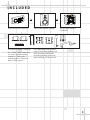
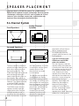
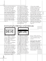
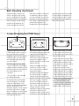
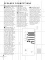
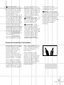
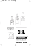
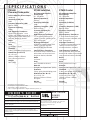
S P E C I F I C AT I O N S
PS1400
Powered Subwoofer
PT800 Satellites
PC600 Center
Built-In Amplifier Power Output
400 Watts
Recommended Amplifier
Power Range
50 – 250 Watts
Recommended Amplifier
Power Range
50 – 250 Watts
Sensitivity (2.83V/1m)
91dB
Nominal Impedance
8 Ohms
Nominal Impedance
8 Ohms
Frequency Response (–6dB)
28Hz to 130Hz
Sensitivity (2.83V/1m)
91dB
Sensitivity (2.83V/1m)
91dB
Crossover Frequency
130Hz
Frequency Response (–6dB)
80Hz to 22kHz
Frequency Response (–6dB)
80Hz to 22kHz
Low-Frequency Transducer
LE14H-3 14" Aquaplas™-cone
woofer with rubber surround, 4"
edge-wound copper voice coil,
and cast-aluminum basket
Crossover Frequencies
650Hz, 3200Hz
Crossover Frequencies
800Hz, 3500Hz
High-Frequency Transducer
1" Pure-titanium dome with
rubber surround, shielded, with
EOS™ waveguide
High-Frequency Transducer
1" Pure-titanium dome with
rubber surround, shielded, with
EOS™ waveguide
Midrange Transducer
4" Titanium inverted dome with
rubber surround and castaluminum basket, shielded
Midrange Transducer
4" Titanium inverted dome with
rubber surround and castaluminum basket, shielded
Low-Frequency Transducer
8" Titanium-alloy inverted dome
with rubber surround and castaluminum basket, shielded
Low-Frequency Transducer
Dual, 6," titanium-alloy inverted
domes with rubber surround and
cast-aluminum basket, shielded
Baffle
IsoPower™
Baffle
IsoPower™
Ports
None (sealed enclosure)
Ports
None (sealed enclosure)
Network
Straight-Line Signal Path™ (SSP)
Network
Straight-Line Signal Path™ (SSP)
Terminals
5-Way, gold-plated binding posts
Terminals
5-Way, gold-plated binding posts
Dimensions (H x W x D)
24" x 13-1/2" x 6"
(610mm x 343mm x 152mm)
Plus grille
Dimensions (H x W x D)
11-5/8" x 26-7/16" x 7-1/4"
(295mm x 672mm x 184mm)
Plus grille
Weight
37 lb (17kg)
Weight
32 lb (15kg)
Baffle
IsoPower™
Ports
2 FreeFlow™ flared
Terminals
5-Way, gold-plated binding posts
Dimensions (H x W x D)
19" x 20" x 15"
(483mm x 508mm x 381mm)
Plus grille and spike feet
Weight
80 lb (36kg)
All features and specifications
are subject to change without notice.
* Trademarks of Dolby Laboratories.
DTS is a registered trademark of Digital Theater Systems, Inc.
OWNER’S GUIDE
PRODUCT
LINE:
MODELS:
PRO SOUND
COMES
HOME™
Performance ™ Series
PS1400, PT800, PC600
D E S I G N G O A L : Bring the thrill of live performance and movie sound to
the home environment by calling on JBL’s professional engineering leadership
T W E E T E R : 1-Inch, Pure-Titanium Dome with Rubber Surround, Mounted
in EOS™ Waveguide
M I D R A N G E : 4-Inch, Titanium Inverted Dome with Rubber Surround and
Cast-Aluminum Basket
L O W - F R E Q U E N C Y : Titanium-Alloy Inverted Dome with Rubber Surround
and Cast-Aluminum Basket in PT800 and PC600; 14-Inch Aquaplas™ with
Rubber Surround, 4-Inch Edge-Wound Copper Voice Coil and Cast-Aluminum
Basket in PS1400
P R O F E S S I O N A L R E F E R E N C E : Studio Monitor and Cinema
Loudspeaker Series
JBL Consumer Products
250 Crossways Park Drive, Woodbury, NY 11797 USA
8500 Balboa Boulevard, Northridge, CA 91329
800-336-4JBL (4525) (USA only)
www.jbl.com
©2001 JBL, Incorporated.
JBL is a registered trademark of JBL, Incorporated.
Part No. 336608-001
X + 0 + Y 2 0 M HZ
OWNER’S GUIDE
PRODUCT
LINE:
MODELS:
Performance™ Series
PS1400, PT800, PC600
D E S I G N G O A L : Bring the thrill of live performance and movie sound to
the home environment by calling on JBL’s professional engineering leadership
T W E E T E R : 1-Inch, Pure-Titanium Dome with Rubber Surround, Mounted
in EOS™ Waveguide
M I D R A N G E : 4-Inch, Titanium Inverted Dome with Rubber Surround and
Cast-Aluminum Basket
L O W - F R E Q U E N C Y : Titanium-Alloy Inverted Dome with Rubber Surround
and Cast-Aluminum Basket in PT800 and PC600; 14-Inch Aquaplas™ with
Rubber Surround, 4-Inch Edge-Wound Copper Voice Coil and Cast-Aluminum
Basket in PS1400
P R O F E S S I O N A L R E F E R E N C E : Studio Monitor and Cinema
Loudspeaker Series
THANK YOU FOR CHOOSING JBL
For more than 50 years, JBL
has been involved in every
aspect of music and film
recording and reproduction,
from live performances to the
recordings you play in your
home, car or office.
We’re confident that the JBL
system you have chosen will
provide every note of
enjoyment that you expected –
and that when you think about
purchasing additional audio
equipment for your home, car
or office, you will once again
choose JBL.
Please take a moment to
complete the enclosed profile
card. It enables us to keep you
posted on our latest advancements, and helps us to better
understand our customers and
build products that meet their
needs and expectations.
JBL Consumer Products
THE PERFORMANCE SYSTEM
The Performance System is an
extremely high-performance
speaker system intended for
uses ranging from premium
two-channel stereo all the way
to 5.1, 6.1 or 7.1 multi-channel
home-theater applications. The
system is modular and consists
of only three system elements:
• A PS1400 powered subwoofer
module incorporating a 14"
driver and internal 400-watt
class D amplifier.
• A PT800 tower module which
contains an 8" mid-bass driver,
a 4" midrange driver and a 1"
dome tweeter with integral
waveguide.
• A PC600 center module which
contains dual 6" drivers and
the same midrange and
tweeter elements as the
tower.
The acoustic behavior of the
PT800 tower and PC600 center
has been matched, giving the
added system flexibility of using
either PT800 towers or PC600
centers at any of the five, six or
seven speaker locations around
the room.
The system is intended for
room sizes of up to 3500 cubic
feet with two subwoofers. If a
larger room is being used, it
is suggested that additional
subwoofer modules be used.
Almost any home installation
can be accommodated by the
use of multiple modules.
The PT800 tower and PS1400
subwoofer can be docked
(stacked), resulting in a
traditional floorstanding
speaker system that can be
used in the front or surround
speaker positions. This system
can be used passively, or in a
bi-amp mode by using the
crossover capabilities of a
high-quality AV receiver or
separates. The PS1400
subwoofers can also be used
as traditional units placed
around the room with the PT800
towers and/or PC600 centers
being stand-, wall-, or
bookshelf-mounted. Both the
PT800 and PC600 speakers
come with wall-mounting
brackets.
Important Note: Do not send a
full-range amplified signal
directly to the PT800 tower
module. The PT800’s are not
designed to reproduce low
bass without a PS1400
powered subwoofer. For
optimum performance, the
PT800 should only receive
signals crossed over at 80Hz
and above.
Declaration of Conformity
We, Harman Consumer International
2, route de Tours
72500 Chateau-du-Loir
France
declare in own responsibility, that the
passive loudspeakers described in this
owner’s manual are in compliance with
technical standards:
EN 50081-1:1992
EN 50082-1:1992
2
Steen Michaelsen
Harman Consumer International
Chateau-du-Loir, France. 2/01
This declaration applies to models PC600 and PT800 only. Information
regarding model PS1400 is included separately with that model only.
INCLUDED
OR
OR
One PC600 Center Speaker
One PT800 Satellite Speaker
Accessories carton containing:
For PT800 and PC600: 4 rubber
pads for use when modules are
wall-mounted; 2 metal wallmounting brackets for secure
wall-mounting; 1 Allen wrench.
For PS1400: 2 gold jumper bars
to connect PS1400 speaker
outputs to PT800 inputs; 2
mounting pillars; 4 long hex
bolts; 1 Allen wrench.
One PS1400 Powered
Subwoofer
3
SPEAKER PLACEMENT
Important Note for PS1400 Placement: The PS1400 features
spiked feet for optimum acoustic performance. However, spikes
can damage certain types of floors, such as hardwood. In such
instances, place furniture coaster pads, available from any
hardware store, between the feet and the floor.
5.1-Channel System
Front Speakers
Center-Channel
Speaker
Surround Speakers
1.52 – 1.83m
(5 – 6 ft.)
The front speakers should be
placed the same distance from
each other as they are from
the listening position. The
PT800 towers should be placed
with tweeters at about the
same height from the floor as
the listeners’ ears will be, or
they may be angled toward the
listeners. This applies whether
or not the PT800 is docked
with the PS1400 subwoofer.
The PC600 center-channel
speaker should be placed
slightly behind the front left
and right speakers, and no
more than two feet above or
below the tweeters of the left
4
and right speakers. It is often
convenient to set the center
speaker on top of the
television set, as shown
in the drawing.
The two surround speakers
should be placed slightly
behind the listening position
and, ideally, should face each
other and be at a level higher
than the listeners’ ears. If that
is not possible, they may be
placed on a wall behind the
listening position, facing
forward. The surround
speakers should not call
attention to themselves.
Experiment with their
placement until you hear a
diffuse, ambient sound
accompanying the mainprogram material heard in the
front speakers.
If you are not docking the
PT800 tower and PS1400
subwoofer modules:
The low-frequency material
reproduced by the subwoofer
is mostly omni-directional, and
this speaker may be placed in
a convenient location in the
room. However, the best
reproduction of bass will be
heard when the subwoofer is
placed in a corner along the
same wall as the front
speakers. Experiment with
subwoofer placement by
temporarily placing the
subwoofer in the listening
position and moving around
the room until the bass
reproduction is best. Place the
subwoofer in that location.
6.1-Channel System
A 6.1-channel system will
consist of a 5.1-channel
configuration, as shown on
page 4, with the addition of a
rear center speaker placed
midway between the two
surround speakers, and
further to the rear than the
surrounds. The rear center
speaker will no more call
attention to itself than the
surround speakers.
Some newer surround-sound
formats utilize left and right
surround channels that are
used for side fill, in addition
to the left and right rear
channels found in 5.1 systems.
Place the left and right
surround speakers on the
sides of the room, at or in
front of the listening position,
facing each other.
7.1-Channel System
MOUNTING OPTIONS
Stacking the PT800 Tower on Top of the PS1400 Subwoofer
Figure 1
Figure 2
Figure 3
Figure 4
Figure 4a
Figure 5
1. Gently place the PT800 tower
upside down on a padded
surface, and remove the 4 bolts
holding the metal plate on the
bottom of the tower using the
included Allen wrench. (Figure 1)
2. Lift the metal plate off of
the speaker (you may need to
insert one end of the Allen
wrench into an empty screw
hole and pull the plate
upwards) and set it aside,
with the four bolts.
5
3. Place the PS1400 subwoofer
in the desired location, as
described in the Speaker
Placement section, and
remove the 4 Allen head bolts
from the mounting plate on top
of the subwoofer. Put these
bolts in a safe place for future
use, should you decide to
change the placement of the
modules, or if you need to
repack the PS1400 for moving
or other purposes. Do not
remove the mounting plate
from the PS1400 subwoofer.
(Figure 2)
4. Place the two trapezoidal
tower supports on the subwoofer mounting plate with
the larger flat surfaces facing
inwards and the protrusions
inserted into the screw holes
in the mounting plate. (Figure 3)
5. Place the metal plate that
you removed from the bottom
of the tower (in Step 1) on top
of the tower supports. The
protruded areas should face
downward and rest on top of
the tower supports, with the
screw holes lined up, and the
notch for the PT800’s terminal
cup should be to the rear.
(Figures 4 and 4a)
6. Secure the assembly
using the 4 long (3-1/2-inch)
hex bolts provided in the
accessories kit included
with the PS1400 module.
7. Carefully place the tower on
the metal plate and secure it
by screwing the 4 hex bolts
removed in Step 1 through the
bottom of the mounting plate
and up into the tower module.
Remember that the bolts must
be screwed in clockwise from
the point of view looking
upwards at the bottom of the
metal plate, and that this may
be counter to your intuition.
(Figure 5)
Wall-Mounting the PT800 Tower or the PC600 Center
I
NOTICE: Important Safety Notes
• Proper selection of mounting
hardware and installation of
the wall and/or corner
brackets are the responsibility
of the customer.
• This product is not intended
for ceiling mounting.
Remove the two hex bolts on
the back of the cabinet. Attach
the metal hanging supports
using the same screws. Before
tightening the bolts, lay a flat
rod, carpenter’s level, or
equivalent, across the top of
the supports. This will ensure
that they are level. Tighten the
bolts securely to maintain an
airtight speaker cabinet.
6
I
I
2
I
I
I
3
I
I
I
4
I
I
I
5
I
I
I
6
I
I
I
7
I
I
I
8
I
I
I
9
I
I
I
I
10 I
I
I
11 I
I
I
12 I
I
I
13 I
I
I
14 I
I
I
15 I
I
1
Two Number 10 round head or
pan head screws should be
used per loudspeaker; only the
top keyhole of each bracket
will be used. The screwhead
should be between 3/8 inch
and 13/32 inch in diameter, and
the screw should be at least
2 inches in length. When
installing screws through
drywall, always use properly
selected wall anchors.
Attach two pieces of the four
self-adhesive rubber pads that
came with the PT800 to the
back of the enclosure in the
two bottom corners so that the
cabinet is spaced evenly from
the wall.
Select a suitable mounting
location on a wall. (The ceiling
is not a suitable mounting
location.)
Drill two pilot holes, appropriately sized for the specific
self-tapping screw or wallanchor that you will be using.
The holes should be 5-1/4
inches apart for the PT800 and
12-7/8 inches apart for the
PC600. The holes should be
1-1/4 inch below where you
want the top of the enclosure
to be positioned.
Wall Mounting (Continued)
Install the two screws into
either a wooden wall-stud or
anchor, and tighten them until
the back of each screwhead is
about 1/8 inch from the wall.
Install the loudspeaker by
slowly moving the cabinet
toward the screws so that the
screwheads clear the larger
circular portion of the top two
keyholes of the two brackets.
Once both screwheads have
entered the keyholes, the
loudspeaker should gently be
lowered onto the screw shafts.
Check that the loudspeaker is
firmly locked onto the screws
by gently pulling the speaker
down and forward.
Corner-Mounting the PT800 Tower
If desired, you may mount the
PT800 towers in the corners of
the room using the optional
PCM800 corner-mount bracket.
PCM800 corner-mounting kits
are available separately from
your JBL dealer.
NOTICE: Important Safety Notes
• Proper selection of mounting
hardware and installation of the
wall and/or corner brackets are
the responsibility of the
customer.
• This product is not intended
for ceiling mounting.
Six Number 10 round head or
pan head screws should be
used per loudspeaker. The
screw head should be between
3/8 inch and 13/32 inch in
diameter, and the screw should
be at least 2 inches in length.
When installing screws through
drywall, always use properly
selected wall anchors.
Attach two pieces of the four
self-adhesive rubber pads that
came with the PT800 to the
angled surfaces of the
enclosure near the bottom to
prevent the speaker from
rattling against the wall and to
allow a firm fit.
Select a suitable mounting
location in a wall corner.
(The ceiling is not a suitable
mounting location.)
Hold the wall bracket against
the wall with the U-shaped
cutouts at the top. Make sure
that it’s level and 3/4 inch below
where you want to have the
top of your PT800 enclosure
positioned. Mark the center of
each of the six mounting holes
using a pencil or sharp
implement. Remove the bracket
and drill six pilot holes as
required for your wood screws
or anchors. Securely fasten the
bracket to the wall. You have
access to the wall screws via
the six large holes on the front
face of the bracket.
Loosen, but do not remove, the
two hex bolts on the back of the
PT800 speaker cabinet. Back
the screws out until the head is
about 1/4 inch from the
enclosure. Install the loudspeaker by slowly lowering the
cabinet towards the U-shaped
cutouts at the front top surface
of the PCM800 bracket so that
the hex bolt shafts rest in the
cutouts. Check that the speaker
is level, then tighten the hex
bolts. Check that the loudspeaker is firmly locked onto all
screws by gently pulling the
speaker down and forward.
7
SPEAKER CONNECTIONS
Subwoofer Controls (PS1400 Only)
¡ On/Auto Switch – When
left in the “Auto” position, the
PS1400 subwoofer will
automatically turn on or go into
standby mode, depending on
whether it detects an audio
signal. When no signal is being
sent, the PS1400 will remain in
standby mode. When it senses
an audio signal, it will
automatically turn itself on and
begin playing. If the PS1400
does not sense a signal for
about twenty minutes, it will
switch itself into standby
mode. When this switch is
left in the “On” position, the
PS1400 will remain on, whether
or not program material is
playing.
™ LF Crossover Switch – This
switch is used to engage the
PS1400’s internal crossover
when it is stacked with the
PT800 tower module, and when
no external crossover is being
used. In the “Normal” position,
the internal crossover is
engaged, and provides an
electronic 130Hz crossover for
the subwoofer which precisely
matches the passive 130Hz
crossover point of the output
terminal to the PT800. The
crossover is precisiondesigned to create a smooth,
integrated floorstanding
speaker system when the
PS1400 and PT800 are stacked.
In the “Separated” position,
the PS1400 provides an
electronic 300Hz rolloff for the
subwoofer, which should be
augmented by the low-pass
crossover in the external
audio/video receiver or
processor. In this mode, the
PT800, whether or not it is
8
¢ Polarity (Phase) Switch –
Use the “Normal” position
whenever the PS1400 and PT800
are stacked and the internal
crossover is used. It should
also be used when an external
crossover is used and all
amplifier channels are in phase.
stacked with the PS1400,
should be given only a highpassed amplifier signal. That
signal should be crossed over
at 80Hz.
£ LF Level Control – This
control allows you to adjust the
level of the subwoofer within a
range of +/– 5dB. Start with the
control positioned at 0dB,
which is flat (neutral bass
level). If bass response is
unsatisfactory, due to either
your room acoustics or as a
matter of taste, experiment
with this control until the
desired bass level is achieved.
This control only affects all
information being received by
the speaker-level input.
The “Reverse” position may be
used when the PS1400 and
PT800 are separated, and due
to wave cancellation, bass
response is improved in this
position. “Reverse” may also
be selected when different
amplifiers are used that
have different polarity
configurations.
MANUAL
¡
ON/OFF
AUTO
SEPARATED
™
LF CROSSOVER
NORMAL
-2
0
£
LF LEVEL
-5
dB
5
¢
REVERSE
POLARITY
NORMAL
∞
LFE LEVEL
MIN
MAX
§
LFE /SUBWOOFER
INPUT
–
+
¶
SYSTEM INPUT
ON
•
POWER
OFF
PERFORMANCE
SERIES
CAUTION
RISK OF ELECTRIC SHOCK
DO NOT OPEN
“WARNING: TO REDUCE THE RISK OF FIRE OR ELECTRIC SHOCK,
DO NOT EXPOSE THIS APPLIANCE TO RAIN OR MOISTURE.”
“AVERTISSEMENT: POUR PRÉVENIR LES RISQUES D’INCENDIE OU
DE CHOC ELECTRIQUE, EVITER D’EXPOSER CET APPAREIL A LA
PLUIE OU A L’HUMIDITE.”
®
NRTL/C
CSA 22-2
UL 1492
PN 336609-001
∞ LFE Level Control – This
control only affects the signal
sent to the LFE input. Adjust
the LFE level by starting with
the level controls on both
PS1400 modules in the
Minimum position. With 5.1, 6.1
or 7.1 source material playing,
advance the LFE Level controls
on both PS1400s slowly until
the desired amount of effects
channel is present. The normal
position for this control is full
clockwise, with LFE adjustments being made via the level
adjustments on your processor.
We have provided this control
because the LFE output level of
AV receivers and processors
can vary from manufacturer to
manufacturer.
If you are using the third or
fourth configurations, where
the main speakers are configured as “Small” and all bass
information is being sent to the
LFE inputs of the PS1400s, the
LFE Level control will operate
on all low- frequency information, and not just for the .1
channel effects.
§ LFE/Subwoofer Input – This
jack accepts either an LFE or
line-level output from the
receiver or processor.
¶ System Input – These
binding posts accept a fullrange, amplified (speakerlevel) output from the receiver
or amplifier. This input should
be used whenever the PS1400
and PT800 modules will be
stacked and the internal
crossover used to form an
integrated floorstanding
speaker system. This input
should be used in that
configuration even if the LFE
input will also be used.
• Power – This is the main
power switch, which must be
turned on for the amplifier and
electronic internal crossover to
function. If you will be away
from home for an extended
period of time, or if the PS1400
will not be used, turn this
switch off to conserve
electricity.
General Connection Information
Separate and strip the ends of
the speaker wire (not supplied)
as shown. Speakers and
electronics terminals have
corresponding (+) and (–)
terminals. Most manufacturers of speakers and
electronics, including JBL, use
red to denote the (+) terminal
and black for the (–) terminal.
The (+) lead of the speaker
wire is sometimes noted with
a stripe or other demarcation.
It is important to connect both
speakers identically: (+) on the
speaker to (+) on the amplifier
and (–) on the speaker to (–)
on the amplifier. Wiring “out of
phase” results in thin sound,
weak bass and a poor
stereo image.
With the advent of multichannel surround-sound
systems, connecting all of the
speakers in your system with
the correct polarity remains
equally important in order to
preserve the proper ambience
and directionality of the
program material.
9
CONNECTIONS AND SETTINGS
There are four possible
configurations for connecting
the PT800 tower and PS1400
subwoofer modules. The PC600
center is always connected
directly to the speaker-level
outputs of the receiver or
amplifier.
Stacked, With Speaker-Level Input to PS1400 and Internal
High-Pass Signal Output to PT800
Use this installation method
with the PT800 and PS1400
stacked.
By using the PS1400’s internal
crossover to process the full
range output of your receiver
or amplifier, the Performance
speakers can behave as a
single full-range system and
produce the highest quality of
sound reproduction that makes
the best use of each transducer
component of each module.
Do not use the PS1400’s
internal crossover and
speaker-level outputs unless
the PS1400 and PT800 are
stacked. If the PT800 is placed
separately – on the wall, on
a shelf or on a stand – you
must use your receiver or
processor’s crossover, which
should be set to 80Hz. The
reason for this is that the
PS1400’s internal crossover is
set at 130Hz, and was customdesigned around the precise
location of the PT800 module
on top of the subwoofer.
This installation method can be
used for non-digital surroundsound formats, such as Dolby*
Pro Logic*, where the receiver
or processor does not have a
subwoofer output or a volumecontrolled preamp (line-level)
output.
10
1. Configure the receiver/
processor for “Large”
speakers for the left and
right channels.
2. Configure the receiver/
processor for “Subwoofer Off”.
3. Configure the receiver/
processor for “Small” for the
center and rear channels.
4. Check the owner’s guide for
your receiver or amplifier to
make sure that the main
speaker terminals will output
a full-range amplified signal.
Connect your receiver or
amplifier’s left and right
speaker terminals to the
binding posts marked
“System Input” ¶ on your
corresponding left and right
PS1400 subwoofer modules.
5. Set the PS1400’s crossover
switch ™ to the “Normal”
position. This will cause the
PS1400 to provide an electronic
130Hz crossover for the
subwoofer that matches the
passive 130Hz crossover point
at the output to the PT800 tower.
6. Set the Polarity (phase)
switch ¢ to Normal, since all
amplifier channels will be in
phase, and in the stacked
configuration, sound-wave
cancellation will not be an
issue.
7. Remove the JBL logo plate
from the mounting plate on top
of the PS1400 by gently prying
it upwards. This will expose
the binding post output
terminals that will provide the
signal for the PT800 module.
It is easiest to connect the
gold jumper bars between the
terminals on the top of the
PS1400 and the terminals on
the rear of the PT800 by
completely unscrewing the
binding post collars first. Insert
the closed loop at one end of
the jumper bar over the PS1400
output terminal, and insert the
open end of the bar around the
PT800’s input. Screw the
collars back onto their
respective posts.
Left Tower
–
Right Tower
+
–
+
–
+
–
+
Center
–
+
–
+
–
+
Left Sub
Right Sub
Receiver
–
+
–
Left Surround
–
+
–
+
+
–
–
+
+
Right Surround
–
+
Note: You may, if desired, use stacked PS1400 and PT800 modules in the surround
speaker positions. These should be wired the same way as shown above for the
front speakers. If you choose this configuration, change the setting on your
receiver/processor for the rear channels from “Small” to “Large”.
11
Stacked, With LFE and Speaker-Level Inputs to PS1400 and Internal
High-Pass Signal Output to PT800
Use this installation method
with the PT800 and PS1400
stacked.
By using the PS1400’s internal
crossover to process the full
range output of your receiver
or amplifier, the Performance
speakers can behave as a
single full-range system and
produce the highest quality
of sound reproduction that
makes the best use of each
transducer component of each
module. In addition, the LFE
(low-frequency effects)
channel provided by some
digital sources can be mixed in
with the low-frequency signal
to provide effects that add
excitement and realism to
movie soundtracks, musical
performances or other
materials.
Do not use the PS1400’s
internal crossover and
speaker-level outputs unless
the PS1400 and PT800 are
stacked. If the PT800 is placed
separately – on the wall, on
a shelf or on a stand – you
must use your receiver or
processor’s crossover, which
should be set to 80Hz. The
reason for this is that the
PS1400’s internal crossover is
set at 130Hz, and was customdesigned around the precise
location of the PT800 module
on top of the subwoofer.
This installation method should
be used for digital surroundsound formats, such as Dolby
Digital or DTS®, where the
receiver or processor has a
subwoofer output or a volumecontrolled preamp (line-level)
output.
12
1. Configure the receiver/
processor for “Large”
speakers for the left and
right channels.
2. Configure the receiver/
processor for “Subwoofer On”.
3. Configure the receiver/
processor for “Small” for the
center and rear channels.
4. Check the owner’s guide for
your receiver or amplifier to
make sure that the main
speaker terminals will output
a full-range amplified signal.
Connect your receiver or
amplifier’s left and right
speaker terminals to the
binding posts marked
“System Input” ¶ on your
corresponding left and right
PS1400 subwoofer modules.
5. Set the PS1400’s crossover
switch ™ to the “Normal”
position. This will cause the
PS1400 to provide an electronic
130Hz crossover for the
subwoofer that matches the
passive 130Hz crossover point
at the output to the PT800 tower.
6. Set the Polarity (phase)
switch ¢ to Normal, since all
amplifier channels will be in
phase, and in the stacked
configuration, sound-wave
cancellation will not be an
issue.
7. Connect the receiver/
processor’s LFE or subwoofer
output to the LFE Input § on
your left and right PS1400
subwoofer modules. If your
receiver/processor has only
one output jack, use a
Y-connector (not included).
Plug the male end of the
Y-connector into your
receiver/processor’s
subwoofer output jack, and
connect each of the two
female ends to separate RCAtype patch cords, then plug the
RCA-type patch cords into the
LFE inputs of the PS1400
modules.
8. Remove the JBL logo plate
from the mounting plate on top
of the PS1400 by gently prying
it upwards. This will expose
the binding post output
terminals that will provide the
signal for the PT800 module. It
is easiest to connect the gold
jumper bars between the
terminals on the top of the
PS1400 and the terminals on
the rear of the PT800 by
completely unscrewing the
binding post collars first. Insert
the closed loop at one end of
the jumper bar over the PS1400
output terminal, and insert the
open end of the bar around the
PT800’s input. Screw the
collars back onto their
respective posts.
Left Tower
–
Right Tower
+
–
+
–
+
–
+
Center
–
+
–
+
–
+
LFE Input
Left
LFE Input
Sub
Right
Sub
Receiver
–
+
–
+
Left Surround
–
+
–
+
Subwoofer/LFE
Y-Connector
not included
–
+
–
+
Right Surround
–
+
Note: You may, if desired, use stacked PS1400 and PT800 modules in the surround
speaker positions. These should be wired using the same speaker-level
connections as shown above for the front speakers but without using the
subwoofer/LFE connections. If you choose this configuration, change the setting
on your receiver/processor for the rear channels from “Small” to “Large”.
13
Stacked, With LFE Input to PS1400 and Externally Crossed-Over
Input to PT800
Use this installation method
with the PT800 and PS1400
stacked.
3. Configure the receiver/
processor for “Small” for the
center and rear channels.
We do not recommend sending
a full-range signal to the
PT800 module. Check the
owner’s guide for your
receiver or amplifier and
processor, and follow the
directions to obtain a highpass 80Hz signal at the left and
right speaker outputs.
4. Check the owner’s guide for
your receiver or amplifier to
make sure that the main
speaker terminals will output a
high-pass amplified signal that
is crossed over at 80Hz.
Connect your receiver or
amplifier’s left and right
speaker terminals to the
speaker binding posts on the
corresponding left and right
PT800 modules. Be sure that
the JBL logo plate is installed
over the output terminals on
the top of the PS1400
subwoofer module.
The LFE (low-frequency
effects) channel provided by
some digital sources can be
sent to the PS1400 module to
provide effects that add
excitement and realism to
movie soundtracks, musical
performances or other
materials.
This installation method should
be used for digital surroundsound formats, such as Dolby
Digital or DTS, where the
receiver or processor has a
subwoofer output or a volumecontrolled preamp (line-level)
output.
1. Configure the receiver/
processor for “Small”
speakers for the left and
right channels.
2. Configure the receiver/
processor for “Subwoofer On”.
14
5. Set the PS1400’s crossover
switch ™ to the “Separated”
position. This will cause the
PS1400 to provide an electronic
300Hz rolloff for the subwoofer
that should be augmented by
the low-pass crossover in the
receiver or processor.
6. Set the Polarity (phase)
switch ¢ to Normal, since
all amplifier channels will be
in phase, and in the stacked
configuration, sound-wave
cancellation will not be
an issue.
7. Connect the receiver/
processor’s LFE or subwoofer
output to the LFE input § on
your left and right PS1400
subwoofer modules. If your
receiver/processor has only
one output jack, use a Yconnector (not included).
Plug the male end of the
Y-connector into your
receiver/processor’s
subwoofer output jack, and
connect each of the two
female ends to separate RCAtype patch cords, then plug the
RCA-type patch cords into the
LFE inputs of the PS1400
modules.
Left Tower
–
Right Tower
+
–
+
–
+
Center
–
–
+
+
Input
Input
LFE
LFE
Left
Sub
Right
Sub
Receiver
–
+
–
+
Left Surround
–
+
–
+
Subwoofer/LFE
Y-Connector
not included
–
+
–
+
Right Surround
–
+
15
Separated, With LFE Input to PS1400 and Externally Crossed-Over
Input to PT800
Use this installation method
with the PT800 and PS1400
separated; that is, the PT800
module mounted on a wall,
shelf or stand.
2. Configure the receiver/
processor for “Subwoofer On”.
We do not recommend sending
a full-range signal to the
PT800 module. Check the
owner’s guide for your
receiver or amplifier and
processor, and follow the
directions to obtain a highpass 80Hz signal at the left and
right speaker outputs.
4. Check the owner’s guide for
your receiver or amplifier to
make sure that the main
speaker terminals will output a
high-pass amplified signal that
is crossed over at 80Hz.
Connect your receiver or
amplifier’s left and right
speaker terminals to the
speaker binding posts on the
corresponding left and right
PT800 modules. Be sure that
the JBL logo plate is installed
over the output terminals on
the top of the PS1400
subwoofer module.
The LFE (low-frequency
effects) channel provided by
some digital sources can be
sent to the PS1400 module to
provide effects that add
excitement and realism to
movie soundtracks, musical
performances or other
materials.
This installation method should
be used for digital surroundsound formats, such as Dolby
Digital or DTS, where the
receiver or processor has a
subwoofer output or a volumecontrolled preamp (line-level)
output.
1. Configure the receiver/
processor for “Small”
speakers for the left and
right channels.
16
3. Configure the receiver/
processor for “Small” for the
center and rear channels.
5. Set the PS1400’s crossover
switch ™ to the “Separated”
position. This will cause the
PS1400 to provide an electronic
300Hz rolloff for the subwoofer
that should be augmented by
the low-pass crossover in the
receiver or processor.
6. Set the Polarity (phase)
switch ¢ to Normal, but
experiment with switching it to
Reverse and then select the
position that produces the best
bass reproduction.
7. Connect the receiver/
processor’s LFE or subwoofer
output to the LFE input § on
your left and right PS1400
subwoofer modules. If your
receiver/processor has only
one output jack, use a
Y-connector (not included).
Plug the male end of the
Y-connector into your
receiver/processor’s
subwoofer output jack, and
connect each of the two
female ends to separate RCAtype patch cords, then plug the
RCA-type patch cords into the
LFE inputs of the PS1400
modules.
Left Tower
–
Right Tower
+
–
+
–
+
Center
–
–
+
+
Input
Input
LFE
LFE
Left
Sub
Right
Sub
Receiver
–
+
–
+
Left Surround
–
+
–
+
Subwoofer/LFE
Y-Connector
not included
–
+
–
+
Right Surround
–
+
17
TROUBLESHOOTING
If there is no sound from any
of the speakers:
• Check that receiver/amplifier
is on and a source is playing.
• Check that the PS1400 is
plugged in and its Power
switch • is switched on.
• Check all wires and connections between receiver/
amplifier and speakers. Make
sure all wires are connected.
Make sure none of the
speaker wires are frayed,
cut or punctured.
• Review proper operation of
your receiver/amplifier.
If there is no sound coming
from one speaker:
• Check the “Balance” control
on your receiver/amplifier.
• Check all wires and connections between receiver/
amplifier and speakers. Make
sure all wires are connected.
Make sure none of the
speaker wires are frayed,
cut or punctured.
• In Dolby Digital or DTS
modes, make sure that the
receiver/processor is
configured so that the speaker
in question is enabled.
If there is no sound from the
center speaker:
• Check all wires and
connections between
receiver/amplifier and
speaker. Make sure all wires
are connected. Make sure
none of the speaker wires are
frayed, cut or punctured.
18
• If your receiver/processor is
set in Dolby Pro Logic mode,
make sure the center speaker
is not in phantom mode.
• If your receiver/processor
is set in Dolby Digital or DTS
mode, make sure the
receiver/processor is configured so that the center
speaker is enabled.
If the system plays at low
volumes but shuts off as
volume is increased:
• Check all wires and connections between receiver/
amplifier and speakers. Make
sure all wires are connected.
Make sure none of the
speaker wires are frayed, cut
or punctured.
• If more than one pair of main
speakers is being used, check
the minimum impedance
requirements of your
receiver/amplifier.
If there is low (or no) bass
output:
• Make sure the connections
to the left and right “Speaker
Inputs” have the correct
polarity (+ and –).
• Make sure the PS1400 is
plugged into an active
electrical outlet.
• Make sure the Power switch
• is on.
• In Dolby Digital or DTS
modes, make sure your
receiver/processor is configured so that the subwoofer
and LFE output are enabled.
• Adjust the Polarity switch ¢
if the PS1400 and PT800 are
not stacked, or if they are
stacked but an external
crossover is being used.
• Adjust the LF Level control £.
• If the LFE input is in use,
adjust the LFE Level control ∞.
If there is no sound from
the surround speakers:
• Check all wires and connections between receiver/
amplifier and speakers. Make
sure all wires are connected.
Make sure none of the
speaker wires are frayed, cut
or punctured.
• Review proper operation of
your receiver/amplifier and its
surround-sound features.
• Make sure the movie or TV
show you are watching is
recorded in a surround-sound
mode. If it is not, check to see
if your receiver/amplifier has
other surround modes you
may use.
• In Dolby Digital or DTS
modes, make sure your
receiver/processor is
configured so that the
surround speakers are
enabled.
• Review the operation of your
DVD player and the jacket of
your DVD to make sure that
the DVD features the desired
Dolby Digital or DTS mode,
and that you have properly
selected that mode using both
the DVD player’s menu and the
DVD disc’s menu.
Staple sales invoice here.
19