1
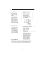
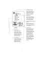
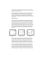
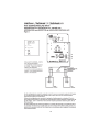
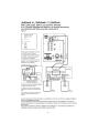
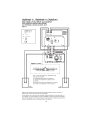
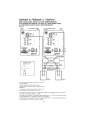
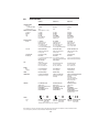
SubSonic 6 i,
SubSonic 5 i,
SubZero i,
Powered Subwoofers
OWNER’S GUIDE
I. IMPORTANT SAFETY INSTRUCTIONS
II. INTRODUCTION
III. QUICKSTART
IV. FEATURES, CONTROLS, AC POWER
A. Sub Volume Control (Figure 1)
B. On Indicator Light (Figure 1)
C. AC Power Connection
D. Sub Cut-Off Frequency Control (Figure 1)
E. High/Speaker Level Terminals (Figure 2)
F. AC Power Socket (Figure 2)
G. External Fuse (Figure 2)
H. Low/Line Level Jacks (Figure 2)
I. Phase Switch (Figure 2)
J. LFE Input/Crossover Bypass Switch (Figure 2)
K. Power Switch (Figure 2)
L. Amplifier Panel (Figure 2)
V. ROOM ACOUSTICS, SUBWOOFER PLACEMENT, MULTIPLE SUBWOOFERS &
SETTING THE CONTROLS
VI. CONNECTING THE SUBWOOFER TO YOUR AUDIO SYSTEM
A. The SubZero i
B. The SubSonic 5i
C. The SubSonic 6i
D. Using Multiple Subwoofers
VII. SET-UP CALIBRATION
VIII. SPECIFICATIONS
www.psbspeakers.com • Phone: (888) 772-0000 or (905) 831-6555
I.
IMPORTANT SAFETY INSTRUCTIONS
1.
2.
3.
4.
5.
6.
7.
Read these instructions.
Keep these instructions.
Heed all warnings.
Follow all instructions.
Do not use this apparatus near water.
Clean only with dry cloth.
Do not block any ventilation openings. Install in accordance with the manufacturer’s
instructions.
Do not install near any heat sources such as radiators, heat registers, stoves, or other
apparatus (including amplifiers) that produce heat.
Do not defeat the safety purpose of the polarized or grounding-type plug. A polarized
plug has two blades with one wider than the other. A grounding type plug has two blades
and a third grounding prong. The wide blade or the third prong are provided for your
safety. If the provided plug does not fit into your outlet, consult an electrician for replacement of the obsolete outlet.
Protect the power cord from being walked on or pinched particularly at plugs, convenience receptacles, and the point where they exit from the apparatus.
Only use attachments/accessories specified by the manufacturer.
Use only with the cart, stand, tripod, bracket, or table specified by the manufacturer, or
sold with the apparatus. When a cart is used use caution when moving the cart/apparatus combination to avoid injury from tip-over.
Unplug this apparatus during lightning storms or when unused for long periods of time.
Refer all servicing to qualified service personnel. Servicing is required when the apparatus has been damaged in any way, such as power-supply cord or plug is damaged, liquid
has been spilled or objects have fallen into the apparatus, the apparatus has been
exposed to rain or moisture, does not operate normally, or has been dropped.
WARNING: To reduce the risk of fire or electric shock, this apparatus should not be
exposed to rain or moisture and objects filled with liquids, such as vases, should not be
placed on this apparatus.
To completely disconnect this equipment from the mains, disconnect the power supply
cord plug from the receptacle.
The mains plug of the power supply cord shall remain readily operable.
8.
9.
10.
11.
12.
13.
14.
15.
16.
17.
The lightning flash with arrowhead symbol within an equilateral triangle,
is intended to alert the user to the presence of uninsulated “dangerous
voltage” within the product’s enclosure that may be of sufficient magnitude to constitute a risk of electric shock to persons.
The exclamation point within an equilateral triangle is intended to alert
the user to the presence of important operating and maintenance (servicing) instructions in the literature accompanying the product.
3
II.
INTRODUCTION
PSB subwoofers are designed to provide the flattest possible frequency
response, full bass extension, low distortion and high output. Frankly, these are
characteristics that most manufacturers would strive for. Our years of experience and our sophisticated design and measurement tools allow us to achieve
ideal subwoofer performance. Beyond these characteristics there are a few other
parameters that we uniquely feel are very important in the design of a subwoofer. First and foremost it is important to us that a PSB subwoofer be musical. In this era of home theater this might at first seem out of step, but we
believe that a musical subwoofer will also sound the most natural when playing
movie soundtracks. Furthermore, an ideal subwoofer should have the ability to
play musically even under conditions of overload or stress. No subwoofer is so
large with its limits so great that it can never be overloaded, especially with
modern movie soundtracks. For this reason PSB subwoofers incorporate very
intelligently applied proprietary limiting circuitry to prevent audible overload.
The limiting circuitry of all PSB subwoofers is a combination of peak limiting
circuits that hold amplifier signal swing to the point just short of the amplifiers
clipping, and compression circuitry that will come in under conditions of long
term overload and reduce the amplifiers gain. The trick is to apply these circuits
in such a way that they don’t squeeze the life out of the music or movie soundtrack, to allow the dynamics to get through while preventing gross distortion.
We do this by being mindful of the dynamics of music and carefully tailoring the
time constants of the circuits to that of music. For example, it is known that
most music is performed with a beat of 80 to 140 beats per minute. Our test
signals are configured to follow this timing and allow maximum transient effect
without distortion on sustained tones.
We go to great lengths to reduce any mechanical noises our subwoofers may
make. Woofers are designed never to bottom harshly. Ports have large radius
end flares to reduce noise from turbulence. Cabinets and amplifiers are designed
so that no air leaks (which can contribute minute amounts of noise) are possible. All of our designs are exhaustively tested. A subwoofers design isn’t complete until the sub’s amp and woofer can survive a 15 hour test of being driven
continuously to maximum output.
SubZero i
The SubZero i has a few unique features worth mentioning. We have mounted
Volume and Crossover controls on the front of the cabinet. Most subwoofers are
tucked away in a dark corner and once in place it can be very inconvenient to
access the controls. Placing volume and crossover knobs on the front of the
cabinet will allow you to adjust these most important functions more conveniently. Despite its modest price the SubZero i contains a simplified version of
our two part limiting circuit and a 100 watt class AB amplifier.
4
SubSonic 5i
The SubSonic 5i has more power and a larger bass unit than the SubZero i. It
also has a very different Class H design for its power amplification. Class H is a
special high efficiency amplifier design. Briefly, audio amplifiers are inherently
inefficient because they are designed to have the capability of delivering great
output power yet spend most of their life delivering fairly low power. Their output devices must deliver current while withstanding the high power supply “rail”
voltages needed for peak outputs. With a Class H design the rail voltages are not
constant. They swing high when the music demands it and stay low during quiet
passages. This is achieved by a sophisticated high frequency switching power
supply. Power dissipated as heat is greatly reduced and more power is available
per dollar of cost. A second benefit is that they tend to have high peak power
relative to their steady state power. The SubSonic 5i, for example, has 150 watts
continuous but is capable of 450 watt peaks. The result is a subwoofer capable
of the great transients required by dynamic music and explosive sound effects.
SubSonic 6i
The SubSonic 6i has a design much like the 5i but with larger drive units and
greater power for even more awesome output. In the words of our engineering
staff it “Cranks pretty good.”
Additional features of the 6i are its high and low level passive and active filtering
circuits that allow greater flexibility in installation.
Whichever PSB subwoofer you have chosen, we hope that you appreciate the
attention to detail that has gone into its design and, of course, that you enjoy
using it. Please take the time to read the following sections about the placement
of your subwoofer, and its connections and adjustments.
We suggest you save the original carton and packing materials, at least for an initial period. Should you ever need to ship or store your PSB subwoofer, it is the
best packaging in which to do so.
III.
QUICKSTART
If you cannot wait to hear your new PSB subwoofer: Turn off all other components, and follow one of the connection diagrams. Connect the supplied power
cord to the AC power socket. Set the PSB subwoofer volume control to its minimum position (counterclockwise), then plug the subwoofer into an active AC
outlet. The same receptacle as the rest of your audio/video system or another
on the same electrical circuit should be used to avoid ground hum. Set the subwoofer’s Sub Cut-Off Frequency control to its midpoint, and the phase switch to
0°. Flip the Power Switch to the on position. Play a bass-rich program source,
and slowly bring up the Sub Volume control (clockwise) until the subwoofer
contributes a natural level of low frequency sound. Now please read the rest of
this guide and fine-tune your installation accordingly—it will be time well spent!
5
6
7
V.
ROOM ACOUSTICS, SUBWOOFER PLACEMENT, MULTIPLE SUBWOOFERS &
CONTROL SETTINGS
Room Acoustics
If you are critical about low-frequency response, there’s quite a bit of useful
experimentation you can do, especially in combination with the crossover, level,
and phase controls of our subwoofers.
Since the earliest days of high fidelity, one of the main challenges for the
designers of speakers, and of their users, has been management of the lowest
frequencies—the deep bass. Many of the most notable developments in speaker
design have been made with a view to getting more bass output from smaller
boxes.
One consideration is the size of the listening room. The larger the volume of air
a speaker must excite, the more acoustic output you will require from it to
achieve the sound levels you want. In any environment, sounds attenuate as you
move farther away from their source, but in smaller rooms that tends to be offset by reinforcement from wall reflections. The larger the space is, the farther
the sound has to travel both to reach the reflecting surfaces and then to get to
your ears, which means it has to be louder to begin with.
With traditional full-range speakers, that involves an intricate matching act
between amplifier power, speaker sensitivity, impedance and power handling.
But the bulk of the power goes to reproducing bass, so the use of powered subwoofers and separate midrange/treble satellites both allows you to be conservative in the amount of power your main amplifier produces, and ensures a good
match between the low-frequency amplifier and the woofer it is paired with.
After size, the most important aspect of a listening room is its shape. In any
room, sound reflects off the walls, ceiling, and floor. If the distance between two
opposite parallel surfaces is a simple fraction of the wavelength of a particular
frequency, notes of that frequency will bounce back and forth in perfect phase—
an effect called a standing wave or room mode.
At some point in the room, this note will be reinforced substantially; at others it
will cancel out almost entirely. If the prime listening seat is placed at either of
these locations, the note will be a horrible boom or virtually non-existent. The
standing waves are different between floor and ceiling, side walls, and end walls,
unless any of these dimensions are the same. An ideal listening room would
have no parallel surfaces—an unusual situation, to say the least—so that such
waves would not establish themselves. The worst kind of room is a perfect
cube.
Almost all rooms are susceptible to some standing waves at low frequencies,
but their effects can be minimized by careful positioning of both the speakers
8
and the listening seat. Moving either of these even a few inches is sometimes
enough to cure—or create—an intolerable sound. The only way to find out what
works best is by experimentation.
With full-range speakers, the range of places you can put the speakers and still
get proper imaging may be fairly limited, and some of these positions may
result in standing waves that can’t be tamed. Things are more controllable
through the use of a subwoofer or two. Positioning of the bass speakers has
almost no impact on imaging, so a subwoofer can be located with only standing
waves in mind.
Subwoofer Placement
There is no argument among audiophiles that the loudest bass output from a
subwoofer comes from corner placement. The natural megaphone-like flaring
outward of walls from a room corner focuses low frequencies—giving them no
place to go but toward you. In the case of subwoofers, there is no automatic
penalty in overall balance for this maximal bass, since your main speakers can
be located elsewhere. It still may be too much bass for your room or (more particularly) your favorite listening spot in the room, but unless you are seated in a
“null” spot, where sound from the sub is cancelled or diminished by out-ofphase reflections from elsewhere, there should be plenty of bass from corner
placement.
PSB subwoofer
PSB
subwoofer
PSB
subwoofer
Most bass output; least even
bass response.
Moderate bass output; more
even bass response.
Lowest bass output; most
even bass.
If you are seated in such a null spot, your only real choices are generally to
move either the subwoofer or your listening position until bass returns to the
point that satisfies. Cranking up the level control or changing the crossover
point almost certainly won’t help much. But flipping the phase control 180
degrees sometimes may make a difference, especially if the null is a product of
cancellations caused by interaction with low frequencies from your main speakers.
If you are in the opposite sort of situation, where direct and reflected bass
waves converge in phase and produce a strong peak at your listening location,
you can—if you like—deal with that both with changes in placement or in the
position of your sub’s level control (or, less likely but possible, the crossover
frequency chosen). We say “if you like” because there is no such thing as too
much bass for some listeners, and we don’t want to be dogmatic. You are defi9
nitely the one who has to be pleased, unless your Significant Other chimes in to
the contrary.
As you go outward from the corner along one wall or another, the general consensus (with which we tend to agree) is that while bass output diminishes
somewhat, it also becomes more uniform throughout the room, with fewer of
the “standing waves” that produce peaks and nulls at various points.
Chances are things won’t be so simple, so the best method for positioning a
subwoofer, although a rather undignified-looking one, is to put the subwoofer in
your listening chair, then play music with lots of bass through the system something with steady low frequencies (such as organ music) or continuous test
tones, not movie material. Move around the room and note where the bass
sounds best; if you place the subwoofer there and yourself in your chair, you
should get the same bass performance. Bear in mind that the test only works if
you have your ears as high off the floor as the subwoofer will be, so don’t be
afraid to crawl around. A recommended starting point for the placement of this
subwoofer would be in either of the front corners of the room (on either side of
the main speakers).
Multiple Subwoofers—Why Two Subs Are Better Than One
Since the objective of most people who buy subs is to make sure of plentiful
low frequencies, the only situation most of us will run into that makes subwoofer placement really difficult is the factor we all fear—the “bad” room that
just won’t let you get satisfying amounts or quality of bass. There are rooms
with troublesome dimensions, especially as you approach a perfect cube (with a
closed door). There is unlikely to be any combination of speaker and listener
position that will be free of obvious acoustic anomalies.
In such a case, the best way to iron out those anomalies is with two subwoofers, placed carefully to work with each other. This can also be true when
the problem is too much, or too uneven, bass. The overall system needs all the
help it can get, and that often means the use of two subwoofers, each one of
which corrects for the acoustic problems excited by the other. For excellent
results from this solution, the two subs don’t have to be identical. It may be
fine, in fact, to use two lesser subs to equal the performance of one with
stronger specs.
The same “crawl around the room” method as previously described should be
used for determining the location of the second subwoofer, except in this
instance one is listening for the minimum amount of bass output. This is a recommended starting point for determining the best placement for your subwoofer(s).
10
Control Settings
Once a reasonably smooth response has been achieved by careful positioning of
the subwoofers, the overall performance can be fine-tuned by means of the controls found on the speaker. An important one is the low-pass filter, which controls the upper limit of the subwoofer’s frequency range. This should be set high
enough to overlap the low frequency cutoff of the satellite speakers, but not high
enough to localize specific sounds from the sub.
If the frequency response of your satellite speakers is such that the subwoofer’s
low-pass filter must be set higher than about 80Hz in order to avoid gaps in the
overall system response, then you might well be able to localize specific sounds
from the sub. This can be very distracting when these sounds appear to come
from beside or behind you. One solution is to make sure the subwoofer is in the
front of the listening area; another is to use multiple subwoofers to make such
sounds more diffuse.
Subwoofers also offer a phase control so the upper frequencies they produce
will not cancel out the lower frequencies of the satellites. A judicious tweaking of
this control can pay major dividends in spectral smoothness in the crossover
area. Phase changes with frequency, however, so these controls may need readjusting every time you vary the cutoff frequency.
Also adjustable is the overall level of the subwoofer’s output. Many users tend to
set this too high at first, in an effort to achieve truly impressive bass. Again,
smooth response is the aim, and it may well be that, if you use them, two subwoofers end up being set differently—if, for example, one is in a corner and the
other is not. It’s all part of the overall-balancing act that is bass management in
real rooms.
We get virtually no inquiries about subwoofer placement from customers, which
is a good indication that it’s not something over which people lose much sleep.
A good subwoofer is such a pleasure when used with a good main speaker that
enjoyment is definitely the rule.
VI.
CONNECTING THE SUBWOOFER TO YOUR AUDIO SYSTEM
There are several ways to connect a subwoofer into a system. For best results
overall, we recommend using Low/Line Level connections.
When making a Low/Line Level connection, be sure to follow the coding on the
cables to maintain left-to-left and right-to-right. Use high quality, well-shielded,
low capacitance RCA cables of minimal necessary length, to avoid picking up
noise in the cable runs. When making a High/Speaker Level connection, in
addition to maintaining left-to-left and right-to-right, be sure to use the coding
of the pair of wires in each speaker cable to maintain phase—+/red/rib/writing to
11
+/red/rib/writing and -/white/smooth/clear to -/white/smooth/clear. We recommend
minimum 16 gauge wire and, for longer runs, larger (lower gauge) wire.
A.
THE SUBZERO™ i
1.
Connecting Home Theater Equipment (SEE FIGURE 3, page 16): You
can use a single RCA cable to connect the Subwoofer Output of your
receiver, integrated amplifier, or preamplifier to either right or left side
of the Low Level Input on the subwoofer.
Home Theater receivers, integrated amplifiers, surround sound processors, and preamplifiers usually have a special Subwoofer Output to
provide the optional (Dolby Digital 5.1) Low Frequency Effects (LFE)
Channel present on many movie and other programming sources. To
reproduce these deep-bass effects (when they are present), supplementing the bass information in the main channels, this output must
be connected to the subwoofer.
The subwoofer output/LFE signal is filtered by most receivers/processors. The subwoofer’s variable low pass filter is usually not required
and should be bypassed by switching the LFE Input/Crossover bypass
switch to active only if the receiver/processor subwoofer/LFE output is
low pass filtered. The default position for this switch is off.
With some Home Theater electronics and settings, connecting the
Subwoofer Output does not provide the low frequencies from normal
stereo music through the subwoofer. If this is true of your system,
you can make two connections. First, connect the Subwoofer Output
from the electronics to the right or left side of the Low Level Input of
the subwoofer, as described above. Then also connect the High Level
Output from the electronics to the High Level Input of our subwoofer,
as described below. When listening to music using High Level Input,
set the LFE Input/Crossover bypass switch to the off position. The
switch would usually be set to active whenever the receiver/processor’s Subwoofer Output is used during playback of movies. Most
Home Theater electronics will not require this second connection,
which, if not required, will produce greater bass than intended.
2.
Connecting Stereo Equipment Using Low/Line Level (SEE FIGURE 4,
page 17): If your receiver or integrated amplifier has preamplifier outputs, or if you are using a separate preamplifier, the preferred connection is from the Preamplifier Output of the electronics to the Low
Level Input of the subwoofer. Use a dual RCA audio cable.
3.
Connecting Stereo Equipment with High/Speaker Level
(SEE FIGURE 5, page 18): You also can get excellent sonic results by
connecting the High/Speaker Level Output of your receiver, integrated
12
amplifier or power amplifier to the High Level Input of the subwoofer.
Use standard speaker cable and maintain polarity + –, as well as right
and left side.
Speaker wires can be run onwards from the subwoofer directly to the
main speakers. This replaces running wires from the receiver or
amplifier to the main speakers. Twist the ends of each input wire from
the electronics together with the corresponding wire to the speakers
and insert them both into each corresponding input binding post of the
SubZero i. Be sure to avoid all contact between wires into the separate binding posts.
B.
THE SUBSONIC™ 5i
1.
Connecting Home Theater Equipment (SEE FIGURE 3, page 16):
Please see the instructions for the SubZero i.
2.
Connecting Stereo Equipment using Low/Line Level (SEE FIGURE 4,
page 17): For this preferred connection, please see the instructions for
the SubZero i. Additionally, you may need to use Y-connectors at the
Preamplifier Output to also send signals to the Power Amplifier/Main
Input.
3.
Connecting Stereo Equipment with High/Speaker Level (SEE FIGURE
5, page 18): You also can get excellent sonic results by connecting the
High/Speaker Level Output of your receiver, integrated amplifier or
power amplifier to the High Level Input of the subwoofer. Use standard
speaker cable and maintain polarity + –, as well as right and left side.
High/Speaker Level Output from the subwoofer allows speaker wires
to be run onwards easily from the subwoofer directly to the main
speakers. This replaces running wires from the receiver or amplifier to
the main speakers. The signals from the SubSonic 5i to the main
speakers are looped through, full-range.
C. THE SUBSONIC 6i
1.
Connecting Home Theater Equipment (SEE FIGURE 3, page 16):
Please see the instructions for the SubZero i.
2.
Connecting Stereo Equipment using Low/Line Level (SEE FIGURE 4,
page 17): If your receiver or integrated amplifier has preamplifier outputs, or if you are using a separate preamplifier, the preferred connection is from the Preamplifier Outputs of the electronics to the Low/Line
Level Inputs of the subwoofer. Use a dual RCA audio cable and maintain
right and left. (You may need to use Y-connectors at the preamplifier
outputs to also send signals to the Power Amplifier/Main Inputs.)
13
Connecting the Low/Line Level Outputs from the subwoofer back to the
Power Amplifier Inputs is an important option. The Low/Line Level
Inputs of the subwoofer are internally processed through an active high
pass filter (at 12dB/octave below 80Hz) to the Low/Line Level Outputs
of the subwoofer. Connecting the Low/Line Level Outputs from the subwoofer back to the Power Amplifier Inputs delivers the processed signal, with reduced low frequency content, to the main speakers. With less
low frequency demands, the main speakers can play louder. Particularly
with smaller and/or less efficient main speakers, relieving speakers other
than the subwoofer of the demands of reproducing low frequencies will
allow greater sound output and dynamic capabilities from the other
speakers and from the system overall.
3.
Connecting Stereo Equipment with High/Speaker Level (SEE FIGURE
5, page 18): You also can get excellent sonic results by connecting the
High/Speaker Level Outputs of your receiver, integrated amplifier or
power amplifier to the High/Speaker Level Inputs of the subwoofer. Use
standard speaker cable and maintain polarity, as well as right and left.
High/Speaker Level Outputs from the subwoofer allow speaker wires
to be run onwards easily from the subwoofer directly to the main
speakers. The signals from the SubSonic 5i to the main speakers are
looped through, full-range. This replaces running from the receiver or
amplifier to the main speakers. The High/Speaker Level Inputs of the
SubSonic 6i are internally processed through a passive high pass filter
(at 6dB/octave below 100Hz) to the Speaker Level Outputs of the subwoofer. Connecting the Speaker Level Outputs from the subwoofer
directly to the main speakers delivers the processed signal, with
reduced low frequency content. With less low frequency demands, the
main speakers can play louder.
D. Using Multiple Subwoofers (SEE FIGURE 6, page 19)
Particularly in difficult rooms with difficult layouts, using two subwoofers
is an alternative to smooth, as well as increase bass response. One subwoofer can be located to increase response, with the second subwoofer
located to smooth response. The wiring of two subs in a system is illustrated in Figure 6 (the two subs do not need to be identical). Please refer
to Section V, Multiple Subwoofers for further information.
VII.
SET-UP CALIBRATION
The following procedure assumes your PSB subwoofer is installed and connected. If possible, work in a team with another person: one listening, one making
subwoofer-control adjustments.
14
A.
Set Sub Volume to 0, Sub Cut-Off Frequency to 50Hz. Set any loudness,
bass and treble, and/or equalizer controls on your preamplifier or integrated
amplifier or receiver, or other components, to their nominal (midpoint or off)
positions. Ensure the LFE Input/Crossover bypass switch is set to off unless
the subwoofer is connected to the LFE/Subwoofer output of your
receiver/processor and the output is low pass filtered.
B.
Play a familiar compact disc, LP, or video soundtrack that includes substantial deep-bass content over an extended section. Your PSB dealer can help
you select a few such titles.
C.
Gradually turn the Sub Volume control clockwise until you achieve natural
balance between the subwoofers deep-bass output and your main left and
right loudspeakers.
D. Slowly turn the Sub Cut-Off Frequency control clockwise to reach the best
mid-bass blend with your main left and right speakers. This will be the point
at which the upper bass retains solid impact and fullness. Boom or muddiness
is the result if the control is too high. A thin, “reedy” quality to the mid-bass
such as deep male voices (FM announcers; Darth Vader) is the result if the
control is too low.
E.
Switch the Phase control between 0° and 180° several times, leaving it in the
position that yields the fullest low to mid bass output. You will now probably
want to repeat steps C & D to double-check the subwoofer blend.
Cycling through steps C & D several times with slightly different settings of both
the Sub Volume and Sub Cut-Off Frequency controls will help you get the most
musical performance from your PSB Subwoofer and your system. The best
combination is that which yields the most solid very-low-bass sounds, without
mid-bass boom or a gap in response between the subwoofer and the main
speakers.
As you will discover, the Sub Cut-Off Frequency and Sub Volume controls are
interactive. Raising the latter while lowering the former can have the effect of
extending deep-bass response somewhat, with a small sacrifice in overall loudness capability (this will still be well beyond the full-range loudness capability of
most systems). In general, for well-recorded acoustic music the lowest Sub
Cut-Off Frequency setting that yields a smooth transition between subwoofer
and main speakers is often the best choice, and will promote deeper low-bass
extension.
Note: The Sub Volume control is not a bass-boost or volume control. It is a
set-and-forget adjustment, not intended for day-to-day adjustment. Use your
preamplifier or receiver/integrated amp tone controls to modify program tonal
balance.
15
16
17
18
19
VIII.
SPECIFICATIONS
SubZero i
FREQUENCY RANGE
Response
On Axis @ 0º ±3dB
LF Cutoff –10dB
AMPLIFIER POWER—INTERNAL
Continuous
Dynamic
Peak
Type
ACOUSTIC DESIGN
Woofer
Crossover
SubSonic 5 i
Subsonic 6i
36-150Hz
32Hz
30-150Hz
27Hz
29-150Hz
26Hz
(RMS, Clipping <10% Time)
100 Watts
130 Watts
260 Watts
Class AB
Discrete MOSFET
Output Devices
150 Watts
225 Watts
450 Watts
Class H/BASH
Discrete MOSFET
Output Devices
225 Watts
325 Watts
650 Watts
Class H/BASH
Discrete MOSFET
Output Devices
8” (203mm)
Polypropylene Cone
Rubber Surround
1½” (38mm) Voice Coil
20 oz (567g) Magnet
+20 oz (567g) Shielding Magnet
10” (250mm)
Polypropylene Cone
Rubber Surround
1½” (38mm) Voice Coil
28 oz (794g) Magnet
+28 oz (794g) Shielding Magnet
12” (300mm)
Polypropylene Cone
Rubber Surround
2” (50mm) Voice-Coil
53 oz (1503g) Magnet
Variable 50Hz-150Hz
24dB/octave Linkwitz-Riley
Low Pass Filter
Variable 50Hz-150Hz
24dB/octave Linkwitz-Riley
Low Pass Filter
Variable 50Hz-150Hz, LR4
24dB/octave Linkwitz-Riley
Low Pass Filter
(Anechoic Chamber)
Internal Volume
0.68 cu ft (19.3 liter)
1.01 cu ft (28.6 liter)
2.38 cu ft (67 liter)
Design Type
Bass Reflex
1 x 8” Front Duct (25mm x 203mm)
Radiused Externally
Video Shielded
Bass Reflex
2 x 2” Front Ports (508mm)
Radiused Internally and Externally
Video Shielded
Bass Reflex
2 x 2 5/8” (66.7mm) Front Ports
Radiused Internally and Externally
(W x H x D)
9 5/8 x 13 1/4 x 14 1/2”
244 x 337 x 368mm
Plus 7/8” (22mm) Feet
12 3/8 x 16 1/2 x 14 7/8”
314 x 419 x 378mm
Plus 7/8” (22mm) Feet
15 x 19 7/8 x 19 1/4”
381 x 505 x 489mm
Plus 1” (25mm) Feet
WEIGHT
Net
Shipping
23.0 lb (10.5kg)/each
27.0 lb (12.3kg)/each
31 lb (14kg)/each
34 lb (16kg)/each
46lb (20.9kg)/each
54lb (24.6kg)/each
FINISH
Black Textured Vinyl
Black Ash Vinyl
Black Ash Vinyl
CONNECTIONS
Low/Line Level/LFE Input
High/Speaker Level Input
Low/Line Level/LFE Input
High/Speaker Level Input
and Output
Low/Line Level/LFE Input and Output
High/Speaker Level Input
and Output
80 Hz High Pass Filter
12 dB/octave Butterworth
High Level High Pass
6 dB/octave Filter
FEATURES
Front Mounted Volume
and Crossover.
Phase, Crossover Bypass and
On-Standby/Off
5-way Binding Posts and
Gold-plated RCAs
Front Mounted Volume
and Crossover.
Phase, Crossover Bypass and
On-Standby/Off
5-way Binding Posts and
Gold-plated RCAs
Front Mounted Volume
and Crossover.
Phase,
On-Standby/Off
5-way Binding Posts and
Gold-plated RCAs
Feet with Adjustable Spikes
& Rubber Levelers
SIZE
or
POWER
Input
Fuse
or
or
LR 106476
LR 106476
120V, 60Hz 220-240, 50/60Hz
120V, 60Hz 220-240V, 50/60Hz
1.6A, 250V T0.8A, 250V,
2.0A, 250V T1.0A, 250V,
*
5mm x 20mm
*
5mm x 20mm
*Manufactured by Littlefuse Type 313 or Equivalent
LR 106476
120V, 60Hz
2.5A, 250V
*
220-240V, 50/60Hz
T1.25A, 250V,
5mm x 20mm
All specifications are subject to change without notice. PSB, Alpha, SubZero and SubSonic are trademarks of Lenbrook Industries Limited.
© 2001. PSB Speakers, a division of Lenbrook Industries Limited. All rights reserved.
20