1
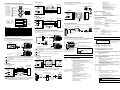
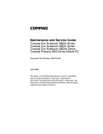
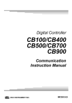
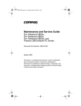
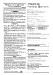
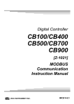
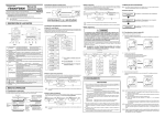
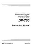
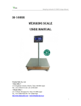
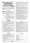
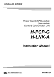
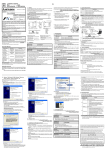
All Rights Reserved, Copyright 2006, RKC INSTRUMENT INC. Host computer Thank you for purchasing this RKC product. In order to achieve maximum performance and ensure proper operation of your new instrument, carefully read all the instructions in this manual. Please place this manual in a convenient location for easy reference. This manual describes the mounting, wiring and specifications only. For the basic operations, see Z-COM PLC Communication Quick Instruction Manual (IMS01T14-E ), Z-COM PLC Communication Data List (IMS01T15-E ) and Z-COM Host Communication Quick Instruction Manual (IMS01T09-E ). For the detail handling procedures and various function settings, please refer to separate Z-COM Instruction Manual (IMS01T07-E ). Programmable controller Z-TIO and Z-DIO modules Power supply 24 V DC 1. PARTS DESCRIPTION Module mainframe Address setting switch Z-COM module (Right side view) Indication lamp (FAIL/RUN) Loader communication connector WARNING CAUTION This is a Class A instrument. In a domestic environment, this instrument may cause radio interference, in which case the user may be required to take adequate measures. This instrument is protected from electric shock by reinforced insulation. Provide reinforced insulation between the wire for the input signal and the wires for instrument power supply, source of power and loads. Be sure to provide an appropriate surge control circuit respectively for the following: − If input/output or signal lines within the building are longer than 30 meters. − If input/output or signal lines leave the building, regardless the length. This instrument is designed for installation in an enclosed instrumentation panel. All high-voltage connections such as power supply terminals must be enclosed in the instrumentation panel to avoid electric shock by operating personnel. All precautions described in this manual should be taken to avoid damage to the instrument or equipment. All wiring must be in accordance with local codes and regulations. To prevent instrument damage or failure, protect the power line and the input/output lines from high currents with a protection device such as fuse, circuit breaker, etc. Prevent metal fragments or lead wire scraps from falling inside instrument case to avoid electric shock, fire or malfunction. Tighten each terminal screw to the specified torque found in the manual to avoid electric shock, fire or malfunction. For proper operation of this instrument, provide adequate ventilation for heat dispensation. Do not connect wires to unused terminals as this will interfere with proper operation of the instrument. Turn off the power supply before cleaning the instrument. Do not use a volatile solvent such as paint thinner to clean the instrument. Deformation or discoloration will occur. Use a soft, dry cloth to remove stains from the instrument. To avoid damage to instrument display, do not rub with an abrasive material or push front panel with a hard object. NOTICE This manual assumes that the reader has a fundamental knowledge of the principles of electricity, process control, computer technology and communications. The figures, diagrams and numeric values used in this manual are only for purpose of illustration. RKC is not responsible for any damage or injury that is caused as a result of using this instrument, instrument failure or indirect damage. RKC is not responsible for any damage and/or injury resulting from the use of instruments made by imitating this instrument. Periodic maintenance is required for safe and proper operation of this instrument. Some components have a limited service life, or characteristics that change over time. Every effort has been made to ensure accuracy of all information contained herein. RKC makes no warranty expressed or implied, with respect to the accuracy of the information. The information in this manual is subject to change without prior notice. No portion of this document may be reprinted, modified, copied, transmitted, digitized, stored, processed or retrieved through any mechanical, electronic, optical or other means without prior written approval from RKC. Indication lamp (RX1/TX1) Communication port COM. PORT1 Communication 1 COM. PORT2 DIP switch 1 2 3 4 5 6 7 8 An external protection device must be installed if failure of this instrument could result in damage to the instrument, equipment or injury to personnel. All wiring must be completed before power is turned on to prevent electric shock, fire or damage to instrument and equipment. This instrument must be used in accordance with the specifications to prevent fire or damage to instrument and equipment. This instrument is not intended for use in locations subject to flammable or explosive gases. Do not touch high-voltage connections such as power supply terminals, etc. to avoid electric shock. RKC is not responsible if this instrument is repaired, modified or disassembled by other than factory-approved personnel. Malfunction can occur and warranty is void under these conditions. Indication lamp (RX2/TX2) Communication port COM. PORT3 Communication 2 COM. PORT4 OFF NO ! RX1/TX1 [Green] RX2/TX2 [Green] (1) This instrument is intended to be used under the following environmental conditions. (IEC61010-1) [OVERVOLTAGE CATEGORY II, POLLUTION DEGREE 2] (2) Use this instrument within the following environment conditions. • Allowable ambient temperature: −10 to +50 °C • Allowable ambient humidity: 5 to 95 % RH (Absolute humidity: MAX. W. C 29.3 g/m3 dry air at 101.3 kPa) • Installation environment conditions: Indoor use Altitude up to 2000 m (3) Avoid the following conditions when selecting the mounting location: • Rapid changes in ambient temperature which may cause condensation. • Corrosive or inflammable gases. • Direct vibration or shock to the mainframe. • Water, oil, chemicals, vapor or steam splashes. • Excessive dust, salt or iron particles. • Excessive induction noise, static electricity, magnetic fields or noise. • Direct air flow from an air conditioner. • Exposure to direct sunlight. • Excessive heat accumulation. (4) Take the following points into consideration when mounting this instrument in the panel. • Ensure at least 50 mm space on top and bottom of the instrument for maintenance and environmental reasons. • Do not mount this instrument directly above equipment that generates large amount of heat (heaters, transformers, semi-conductor functional devices, large-wattage resistors). • If the ambient temperature rises above 50 °C, cool this instrument with a forced air fan, cooler, or the like. However, do not allow cooled air to blow this instrument directly. • In order to improve safety and the immunity to withstand noise, mount this instrument as far away as possible from high voltage equipment, power lines, and rotating machinery. High voltage equipment: Do not mount within the same panel. Power lines: Separate at least 200 mm. Rotating machinery: Separate as far as possible. • Be sure the Z-COM module and functional modules (Z-TIO, Z-DIO) are joined when using them. Space required between each module vertically When the module is mounted on the panel, allow a minimum of 50 mm at the top and bottom of the module to attach the module to the mainframe. When normal: A green lamp is on (RUN) Self-diagnostic error: A green lamp flashes (FAIL) Instrument abnormality: A red lamp is on (FAIL) The green lamp is lit when data corresponding to communication 1 (COM. PORT1/COM. PORT2) is sent or received. The green lamp is lit when data corresponding to communication 2 (COM. PORT3/COM. PORT4) is sent or received. Used to connecting the Operation panel or Host computer. [RS-485 or RS-422A] The COM. PORT2 is used for the extension of the SRZ unit. [RS-485 or RS-422A] Used to connecting the programmable controller (PLC), Operation panel or Host computer. [RS-485 or RS-422A] The COM. PORT4 is used for the extension of the SRZ unit. [RS-485 or RS-422A] This is a connector to be connected to converter and personal computer when loader communication is performed. 76.9 (5) • • • This instrument is Permanently connected to equipment, please take the following points. A switch or circuit-breaker shall be included in the building installation. It shall be in close proximity to the equipment and within easy reach of the operator. It shall be marked as the disconnecting device for the equipment. 2.2 Joining Each Module Before joining the Z-COM module and functional modules, use the DIP switches to make the communication settings. For the setting procedure, see Z-COM PLC Communication Quick Instruction Manual (IMS01T14-E ). The maximum number of functional modules (Z-TIO-A/B, Z-DIO) described in the following can be joined per Z-COM module. For details on joining functional modules with the Z-COM module, see the Z-TIO INSTRUCTION MANUAL (IMS01T01-E ). • When joining functional modules of the same type: Up to 16 modules • When joining functional modules of two or more different types: Up to 31 modules (However, the maximum joinable number of functional modules of the same type is 16.) SRZ unit Set unit address of SRZ unit with address setting switch. Z-COM module • Sets communication speed, communication protocol and data bit configuration corresponding to each of communication 1 and communication 2. • Sets dip switch setting validity/invalidity. Base 16 Z-TIO-A/B modules Joint connector Used to mechanically and electrically connect each module. Holes for screws to fix the base to a panel, etc. Customer must provide the M3 screws. Power supply terminals These are terminals to supply power to the Z-COM module or joined function modules. 1 2 Mounting bracket Used to fix the module on DIN rails and also to fix each module joined together. 5 Terminal 3, 4 and 5 These terminals cannot be used for the Z-COM module. (Usage is prohibited.) 15 Z-DIO modules Functional modules: Up to 31 modules When the number of correspondence channels is specified using the model code, only the amount of data corresponding to the specified number of channels can be sent or received (PLC communication only). The number of the correspondence channels 64 channels 48 channels 3 4 Approx. 50 (Unit: mm) Communication cables 50 mm or more Procedure for mounting or removing The procedure for mounting or removing the Z-COM module is the same as that of the function module (Z-TIO or Z-DIO). Both DIN rail mounting and screw mounting are available. For details on module mounting or removing, see the Z-TIO INSTRUCTION MANUAL (IMS01T01-E ). ! Bottom [Example] When the Z-TIO-A/B and Z-DIO modules are joined Mounting holes (M3 screw) Space for communication cables must be considered when installing. 3. WIRING Top Switch Address setting switch DIP switch Depth for communication cables mount type module ON Communication port (modular connector) and Communication connector COM. PORT1 (Communication 1) COM. PORT2 (Communication 1) COM. PORT3 (Communication 2) COM. PORT4 (Communication 2) Loader communication connector (Unit: mm) WARNING Indication lamp FAIL/RUN [Green or Red] 6.7 2.1 Mounting Cautions PLC communication Accessories check Safety precautions ! 30 To prevent electric shock or instrument failure, always turn off the power before mounting or removing the instrument. Host communication The above manuals can be downloaded from our website: URL: http://www.rkcinst.com/english/manual_load.htm Z-COM Installation Manual (This manual) ........................................................................ 1 Z-COM PLC Communication Quick Instruction Manual (IMS01T14-E )....................... 1 Z-COM PLC Communication Data List (IMS01T15-E ) ................................................. 1 Z-COM Host Communication Quick Instruction Manual (IMS01T09-E ) ...................... 1 Joint connector cover (KSRZ-517A).................................................................................. 2 Power terminal cover (KSRZ-518A).................................................................................. 1 76.9 SRZ unit Z-COM module IMS01T05-E2 2.3 Dimensions 2. MOUNTING 100 Z-COM Communication Extension Module Installation Manual The Z-COM module joins with functional modules (Z-TIO, Z-DIO modules) and performs PLC communication and host communication. The combination of Z-COM module and functional module is called an SRZ unit. 5 Module Type Controller SRZ 32 channels 16 channels Z-TIO-A/B module Z-DIO module 64 channels (However, up to 16 modules) 48 channels (However, up to 16 modules) 128 channels (Up to 16 modules) 96 channels (Up to 12 modules) 64 channels (Up to 8 modules) 32 channels (Up to 4 modules) 32 channels 16 channels WARNING To prevent electric shock or instrument failure, do not turn on the power until all the wiring is completed. 3.1 Wiring Cautions • To avoid noise induction, keep communication signal wire away from instrument power line, load lines and power lines of other electric equipment. • If there is electrical noise in the vicinity of the instrument that could affect operation, use a noise filter. − Shorten the distance between the twisted power supply wire pitches to achieve the most effective noise reduction. − Always install the noise filter on a grounded panel. Minimize the wiring distance between the noise filter output and the instrument power supply terminals to achieve the most effective noise reduction. − Do not connect fuses or switches to the noise filter output wiring as this will reduce the effectiveness of the noise filter. • Power supply wiring must be twisted and have a low voltage drop. • For an instrument with 24 V power supply, supply power from a SELV circuit. • A suitable power supply should be considered in the end-use equipment. The power supply must be in compliance with a limited-energy circuits (maximum available current of 8 A). • Supply the power to only one of the joined modules. When power is supplied to any one of the joined modules, all of the joined modules will receive power. • Select the power capacity which is appropriate for the total power consumption of all joined modules and the initial current surge when the power is turned on. Power consumption (at maximum load): 30 mA max. (at 24 V DC) Rush current: 10 A or less • When connecting the wiring to the power supply terminals on the base, use the specified solderless terminals. Only these specified solderless terminals can be used due to the insulation between the terminals. φ 5.5 MAX Screw Size: M3 × 7 (with 5.8 × 5.8 square washer) φ 3.2 MIN φ 3.2 Recommended tightening torque: 0.4 N・m (4 kgf・cm) Applicable wire: Solid/twisted wire of 0.25 to 1.65 mm2 Specified solderless terminal: Manufactured by J.S.T MFG CO., LTD. 9.0 mm Circular terminal with isolation V1.25−MS3 5.6 mm (M3 screw, width 5.5 mm, hole diameter 3.2 mm) 3.2 Terminal Configuration Base 1 3 2 4 Power supply terminals Supply the power to only one of the 1 5 + 2 − joined modules. When power is supplied to any one of the joined modules, all of the joined modules will receive power. 24 V DC Terminals 3, 4 and 5 (Usage is prohibited.) (Continued on the next page ) 3.3 Contents of the Communication Port Z-COM module COM. PORT3 The contents of the modular connector signal are all the same from COM. PORT1 to COM. PORT4. Communication 1 Connector for Host computer or Operation panel connection [RS-422A/RS-485] Communication 2 Connector for PLC, Host computer or Operation panel connection [RS-422A/RS-485] (−) Communication port (+) Modular connector COM. PORT1 1 Pin number COM. PORT2 (+) (−) Communication port COM. PORT3 6 COM. PORT4 OMRON PLC SYSMAC series Paired wire RS-422A R (A) 1 SDB R (B) 2 SDA SG 3 SG T (B) 4 RDB T (A) 5 RDA SG 6 When the host computer has a USB connector, connect the USB communication converter between the host computer and the Z-COM module. Z-COM module COM. PORT1 Shielded twisted pair wire (+) (+) RS-485 (−) MITSUBISHI MELSEC series Z-COM module COM. PORT3 The Z-COM module’s COM.PORT is internally connected. Two systems are used for communication. COM. PORT1 Communication 1 (−) COM. PORT2 (+) RS-485 T/R (A) 1 SDB T/R (B) 2 SDA SG 3 SG 4 RDB 5 RDA COM. PORT3 Communication 2 COM. PORT4 RS-422A SG RS-485A Pin No. Signal name Symbol Pin No. Signal name Symbol 1 2 3 4 5 6 Receive data Receive data Signal ground Send data Send data Signal ground R (A) R (B) SG T (B) T (A) SG 1 2 3 4 5 6 Send/receive data Send/receive data Signal ground Unused Unused Signal ground T/R (A) T/R (B) SG SG PLC MITSUBISHI MELSEC series Paired wire *R 6 Shielded twisted pair wire (Modular connector) *R: Termination resistor (PLC side) Up to four SRZ units can be multi-drop connected to one PLC communication port. Customer is requested to prepare a communication cable fit for the Z-COM to be connected by the PLC. RS-232C SRZ unit 1 Connected to communication port * Communication cable (RKC product) is sold separately. (−) (+) (+) MITSUBISHI MELSEC series (+) (+) (−) (−) PLC MITSUBISHI MELSEC series R (A) 1 SDB R (B) 2 SDA SG 3 SG T (B) 4 RDB T (A) 5 RDA SG 6 (Modular connector) T (B) 4 4 R (A) T (A) 5 5 R (B) SG 6 Paired wire The termination resistor is built in to the COM-K. USB communication converter COM-K (RKC product) Loader communication Connected to loader communication connector of the Z-COM module USB communication converter COM-K (RKC product) Connected to loader communication connecter The termination resistor is built in to the COM-K. Host computer USB cable (COM-K accessory) Connected to USB connecter Loader communication cable (W-BV-01) [Option] Connected to USB port of a personal computer • When the COM. PORT3 is used: Insert the termination resistor to COM. PORT4. (16 units maximum) When multidrop connected, connect a termination resistor to the Z-COM module at the farthest end of the communication line. Termination resistor connector (Sold separately) W-BW-01 (For RS-485) W-BW-02 (For RS-422A) [120 Ω 1/2 W] When preparing a cable of connecting the computer link module belonging to the MITSUBISHI MELSEC series to our Z-COM module, cross each pair of wires the A and B terminal positions on their terminal boards are not symmetrical. R (A) 1 T (A) R (B) 2 T (B) SG 3 SG T (B) 4 R (A) T (A) 5 R (B) SG 6 When the interface of host computer is RS-232C (RS-232C ↔ RS-422A) Host computer RS-232C/RS-422A converter COM-A (RKC product) RS-422A Connected to COM. PORT1 RS-232C W-BF-28* W-BF-02* Connected to COM. PORT1 Interface: Base on RS-422A, EIA standard Base on RS-485, EIA standard Protocol: • MITSUBISHI MELSEC series special protocol (type 4) − A compatible, 1C frame, ACPU common command (WR/WW) (A series, FX2N/FX2NC series or FX3U/FX3UC series) − A compatible, 1C frame, AnA/AnUCPU common command (QR/QW) (AnA/QnA series, Q series) D register, R register, W register, ZR register • OMRON SYSMAC series special protocol − C mode command (RD/WD) DM register, EM register (Specify the bank No. +10), EM register (Specify the current bank) Shielded twisted pair wire When the interface of host computer is RS-232C, connect the RS-232C/RS-422A converter between the host computer and the Z-COM. COM Shielded twisted pair wire PLC communication Host computer RS-422A Z-COM Connected to COM. PORT2 General specifications Power supply voltage: Power supply voltage range: 24 V DC 21.6 V to DC 26.4 V DC [Including power supply voltage variation] Current consumption: 30 mA max. Rush current: 10 A or less Allowable ambient temperature: −10 to +50 °C Allowable ambient humidity: 5 to 95 %RH (Absolute humidity: MAX.W.C 29.3 g/m3 dry air at 101.3 kPa) Installation environment conditions: Indoor use Altitude up to 2000 m Weight: Approx. 110 g Standard Safety standard: CE marking: D-SUB 9P connector UL: UL61010-1 cUL: CAN/CSA-C22.2 No. 61010-1 LVD: EN61010-1 OVERVOLTAGE CATEGORY II, POLLUTION DEGREE 2, Class II (Reinforced insulation) EMC: EN61326 AS/NZS CISPR11 (equivalent to EN55011) 5. MODEL CODE • When the COM. PORT1 is used: Insert the termination resistor to COM. PORT2. SRZ unit 3 Paired wire (Modular connector) Protocol: Communication speed: Maximum connections: C-Tick: 4. SPECIFICATIONS Z-COM module COM. PORT1 RS-422A RS-422A T (B) Base on RS-422A, EIA standard Base on RS-485, EIA standard RKC communication or Modbus-RTU 4800 bps, 9600 bps, 19200 bps, 38400 bps Sixteen SRZ units per communication port of Host computer Code (4) to (6) are for quick start codes to specify software configurable settings. If not specified, these codes will not be printed on labels and all settings will be factory default. (1) Communication 1 (COM. PORT1, COM. PORT2) 4: RS-422A 5: RS-485 RS-422A For the termination resistor of PLC side, see the PLC Instruction Manual. (−) 3 Connected to COM.PORT1 When the interface of host computer is RS-422A For termination resistor of Z-COM modules, see 3.6 Z-COM Module Termination Resistor. Paired wire 3 For the termination resistor of PLC side, see the PLC Instruction Manual. If communication errors occur frequently due to the operation environment or the communication distance, connect termination resistors to the Z-COM module and the other party unit. Z-COM module COM. PORT3 SG Connected to USB connector of COM-K (1) (2) (3) (4) (5) (6) For termination resistor of Z-COM modules, see 3.6 Z-COM Module Termination Resistor. Connected to COM.PORT3 * Communication cable (RKC product) is sold separately. SRZ unit 3 (4 units maximum) T (A) Z-COM-A - If communication errors occur frequently due to the operation environment or the communication distance, connect termination resistors to the Z-COM module and the other party unit. W-BF-02* 2 SRZ unit 2 Connected to communication connector SRZ unit 2 2 W-BF-02* W-BF-28* Connected to COM. PORT3 Connected to COM.PORT4 R (B) Host communication Interface: If communication errors occur frequently due to the operation environment or the communication distance, connect termination resistors to the Z-COM module and the other party unit. Programmable controller (PLC) W-BF-01* SG 3.6 Z-COM Module Termination Resistor Connected to COM.PORT2 Host computer 1 SRZ unit 1 RS-422A RS-232C/RS-422A converter Connected to COM-A (RKC product) COM.PORT1 W-BF-02* 3.4 Example of Connection to PLC 1 Connect a USB communication converter between the host computer and the Z-COM module. Up to 16 SRZ units can be connected to a host computer communication port. The communication cable must be provided by the customer. Connected to COM.PORT2 R (A) Shielded twisted pair wire 3.5 Example of Connection to the Host Computer Connected to COM.PORT1 USB cable (COM-K accessory) RS-422A (Modular connector) COM The six-pin type modular connector should be used for the connection to the Z-COM module. (Recommended manufacturer and model: Hirose Electric, TM4P-66P) Connected to USB port of a personal computer Host computer (−) (Modular connector) Z-COM module internal block diagram • OMRON SYSMAC series − High-order link unit C200H-LK202-V1, C500-LK203, C120-LK202-V1 (SYSMAC C series), etc. − CPU unit with a built-in communication port CPU unit of SYSMAC CS1 series and CJ1 series − Serial communication board CS1W-SCB41 (SYSMAC CS1 series), CJ1W-SCU41 (SYSMAC CJ1 series), etc. When the host computer has a USB connector OMRON SYSMAC series Connected to communication connector * Communication cable (RKC product) is sold separately. Communication speed: 4800 bps, 9600 bps, 19200 bps, 38400 bps Maximum connections: Four SRZ units per communication port of PLC Usable PLC type: • MITSUBISHI MELSEC series − Computer link unit AJ71UC24, A1SJ71UC24-R4, A1SJ71C24-R4, etc. The unit which AnA/AnUCPU common command (type 4) can use. − Serial communication unit AJ71QC24N, A1SJ71QC24N, QJ71C24, etc. The unit which AnA/AnUCPU common command (type 4) can use. − Adapter FX0N-485ADP, FX2NC-485ADP, FX3U-485ADP − Expanded function board FX2N-485BD, FX3U-485-BD (2) Communication 2 (COM. PORT3, COM. PORT4) 4: RS-422A 5: RS-485 (3) Quick start code (Communication protocol selection) N*: No quick start code (Configured as factory default) 1: Specify quick start code 1 (4) Communication 1 protocol (COM. PORT1, COM. PORT2) [Quick start code 1] No code: No specify quick start code 1: RKC communication (ANSI X3.28) 2: Modbus (5) Communication 2 protocol (COM. PORT3, COM. PORT4) [Quick start code 1] No code: No specify quick start code 1: RKC communication (ANSI X3.28) 2: Modbus 3: MITSUBISHI MELSEC series special protocol (PLC communication) AnA/AnUCPU common command (QR/QW) (AnA/QnA series, Q series) 4: 5: OMRON SYSMAC series special protocol (PLC communication) MITSUBISHI MELSEC series special protocol (PLC communication) ACPU common command (WR/WW) (A series, FX2N/FX2NC series or FX3U/FX3UC series) (6) The number of the correspondence channels (Only PLC communication) No code: No specify quick start code A: 16 CH B: 32 CH C: 48 CH D: 64 CH * Factory set value when there is not specification of quick start code: Communication 1/communication 2 RKC communication The number of the correspondence channels: 64 CH Modbus is a registered trademark of Schneider Electric. The name of each programmable controller (PLC) means the products of each manufacturer. Company names and product names used in this manual are the trademarks or registered trademarks of the respective companies. ® RKC INSTRUMENT INC. The first edition: JUN. 2006 [IMQ00] The second edition: DEC. 2006 [IMQ00] HEADQUARTERS: 16-6, KUGAHARA 5-CHOME, OHTA-KU TOKYO 146-8515 JAPAN PHONE: 03-3751-9799 (+81 3 3751 9799) E-mail: [email protected] FAX: 03-3751-8585 (+81 3 3751 8585) DEC. 2006