1
INSTALLATION & PROGRAMMING MANUAL
ISM4
INTELLIGENT SYSTEM MANAGER
ISM4 INSTALLATION & PROGRAMMING MANUAL
2
TABLE OF CONTENTS
INTRODUCTION ....................................................................................................................................................... 3
ISM4 FEATURE DESCRIPTIONS ............................................................................................................................ 4
ISM4 FRONT PANEL FEATURES....................................................................................................................... 4
ISM4 REAR PANEL FEATURES ......................................................................................................................... 5
ISM4 BOTTOM PANEL FEATURES.................................................................................................................... 7
SYSTEM APPLICATIONS ...................................................................................................................................... 11
HOME THEATER SYSTEM (Figure 4) .............................................................................................................. 11
Other Applications........................................................................................................................................... 11
MULTI-ZONE A/V SYSTEM (Figure 5).............................................................................................................. 12
INSTALLATION ...................................................................................................................................................... 13
CONNECTIONS ...................................................................................................................................................... 13
HOME THEATER SYSTEM (Figure 4) .............................................................................................................. 13
MULTI-ZONE SYSTEM (Figure 5)..................................................................................................................... 14
OTHER CONNECTIONS .................................................................................................................................... 16
RS232 ............................................................................................................................................................. 16
EXPANSION ................................................................................................................................................... 16
PROGRAMMING..................................................................................................................................................... 18
SOURCE ON/OFF MACROS ............................................................................................................................. 18
COMMAND STRUCTURE .................................................................................................................................. 18
NAVIGATING AND EDITING MACROS ............................................................................................................ 18
PROGRAMMING MACROS ............................................................................................................................... 19
MACRO PROGRAMMING TABLE .................................................................................................................... 19
Learn IR .......................................................................................................................................................... 20
IR Learn Error ................................................................................................................................................. 20
No Delay – with additional Command Structures in the Macro ...................................................................... 20
Delay – with additional Command Structures in the Macro............................................................................ 21
No Delay – no additional Command Structures in the Macro......................................................................... 21
Test Macro ...................................................................................................................................................... 21
Program Remaining Macros ........................................................................................................................... 21
Exit Edit Mode ................................................................................................................................................. 21
Test ISM4 (All Macros) ................................................................................................................................... 21
PROGRAMMING RC68 ON/OFF TRIGGER COMMANDS ............................................................................... 22
RC68 Discrete ON/OFF Trigger Command Programming ............................................................................. 22
RC68 Toggle ON/OFF Trigger Command Programming ............................................................................... 22
RS232 CONTROL AND PROGRAMMING ........................................................................................................ 24
RS232 Com Port Settings............................................................................................................................... 24
RS232 Command Strings ............................................................................................................................... 24
ISM4 Queries .................................................................................................................................................. 24
CLONING THE ISM4 .......................................................................................................................................... 26
OPERATING THE ISM4.......................................................................................................................................... 27
System ON Mode ................................................................................................................................................ 27
System OFF Mode .............................................................................................................................................. 27
RC68 Triggered Commands ............................................................................................................................... 27
RS232 Triggered Commands ............................................................................................................................. 28
APPENDIX .............................................................................................................................................................. 29
NAVIGATING AND EDITING MACROS ............................................................................................................ 29
Normal Operating Mode.................................................................................................................................. 29
Edit Mode - Navigate Macros.......................................................................................................................... 30
IR Learn Mode ................................................................................................................................................ 31
Delay Program Mode ...................................................................................................................................... 32
SPECIFICATIONS................................................................................................................................................... 33
ISM4 INSTALLATION & PROGRAMMING MANUAL
3
INTRODUCTION
Congratulations and thank you for purchasing the Xantech ISM4 Intelligent System Manager. The ISM4 is the
answer to the age old problem of simply and inexpensively keeping Home Entertainment System devices in sync.
The ISM4 can sync up to four IR controlled devices when referenced to one of those devices, typically a Video
Monitor, Home Theater A/V Receiver or Whole House Audio/Video Entertainment System Controller. All four
system devices are referenced to the ISM4 via Xantech Sensing Modules. There are 6 different sensors that can
be used to detect voltage, contact closure, video, audio, light or current. When the System Reference Device is
turned ON, the ISM4 will detect the change of state for the referenced device (from OFF to ON) and ‘look’ at the
state of the other devices. If any or all are OFF, the ISM4 will automatically output IR Commands to turn those
devices ON for proper system sync.
The ISM4 Processor constantly scans the Sense Inputs, whether any of the system devices are ON or not. This
serves multiple purposes. First, when the System Reference Device is ON, it keeps the other system devices ON.
That doesn’t just mean at the initial power up, but for as long as the reference device is ON. Some devices such
as DVD players will time out after a certain period of inactivity. If a device were to time out or otherwise turn OFF,
(as long as the System Reference Device is ON) when the ISM4 Processor scans the Sense Inputs, if any device
is OFF the ISM4 will output the proper IR Command to turn the device ON and restore proper system sync.
The opposite is also true. If the System Reference Device is OFF and the ISM4 detects any of the other three
devices are ON, the ISM4 will output the proper IR Command(s) and turn it/them OFF to restore proper system
sync.
In addition to issuing power commands to maintain sync, each device can have a macro of up to five IR
Commands and Delays associated with the sync mechanism so anytime a device is synced to the system, a
default mode for each device (and ultimately the system) can be implemented. This allows the reference device to
be set to a specific input at specific volume and audio mode (depending upon device capability). Sources can be
set to Play (DVD/CD, Media Servers, etc) or tune to a specific channel (Cable, Satellite, XM, Sirius, AM/FM).
There is no special remote or keypad required to activate the ISM4. It will automatically respond to the status of
the System Reference Device to sync the other system devices. However, the ISM4 can be controlled via IR. For
IR control, the ISM4 responds to Xantech RC68 Commands. Any programmable controller that can learn RC68
Commands can be used with an ISM4. There is an IR Control Input that can be integrated with most IR repeater
systems and an IR Receiver Jack that is compatible with any Xantech IR Receiver with a stereo mini plug. (291
Series or ‘Dash 30’ Type 480-30, 490-30 etc). The IR Inputs will also pass through IR Commands, allowing direct
control of the system devices, so typically no additional connecting block or other IR system components are
required.
The RS232 Protocol allows for a bi-directional interface between the ISM4 and the RS232 Control Device.
Incoming ASCII Text Commands can be associated with IR Commands for Discrete ON/OFF or Toggle Power of
the System Reference Device, Query Source Power State and request general System Info. The ISM4 will return
an ASCII Text Status Message to the control device for use as system status indication or other logic as
implemented per system design.
The ISM4 is a stand-alone programmed device and does not require any programming software for setup. A
simple, logical progression of IR Code Learning is used with each step prompted by the Front Panel LED's.
Specific LED modes indicate which Source macro is being programmed right down to which step in the macro,
and how many seconds are in the delay. All programming can be tested right from the ISM4 while learning for
individual code confirmation or when programming is complete for system function confirmation. ISM4
Programming can be cloned from one unit to another via the RS232 Port on the Rear Panel.
Multiple ISM4 Modules can be linked for expansion in systems with more than four devices. All devices will be
synced to the System Reference Device on the Primary Module.
Xantech ISM4 – Intelligent System Management made simple.
ISM4 INSTALLATION & PROGRAMMING MANUAL
4
ISM4 FEATURE DESCRIPTIONS
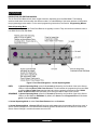
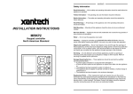
Figure 1 – ISM4 Front Panel Features
ISM4 FRONT PANEL FEATURES
1. IR Learning Eye. The IR Learning Eye allows teaching IR Commands to the ISM4 for programming Source
ON and OFF Macros and Command Structures.
2. Source 1-4 LED’s. These LED’s are primarily used to indicate the sensed state of a corresponding system
device (Source 1-4). When a sensed device is ON, the LED for that device will illuminate solid green. When
that device is OFF the LED will be OFF. A Source LED will flash green when the ISM4 is outputting IR for that
source. These LED’s will also illuminate individually during IR Programming to indicate which device the IR
Commands being learned are being associated with. Several of the function buttons on the front panel are
capable of launching different functions based on the current programming state and the duration of the
button press. The allowed elapsed times are; 1 second, 2 seconds, 5 seconds and 10 seconds. To eliminate
the burden on the programmer to have to keep track of time, the ISM4 will prompt the programmer when all
but the 1 second elapsed time intervals have expired. This is true for all buttons that have time
dependencies. Upon initiation of a press of a button with time dependencies, the unit starts tracking time.
Upon crossing the 2 second threshold, the unit will quickly flash the current active SOURCE LED. If the
button remains pressed beyond this point the unit continues to monitor elapsed time. After 5 seconds of
continuously pressing the button, the current active SOURCE LED will blink once again. Finally after 10
seconds of a continuous press, the LED will blink a third time. Given that there is not time dependency that
exceeds 10 seconds the unit starts to blink rapidly to indicate that the max time duration has been exceeded.
•
•
•
•
First Blink:
Second Blink:
Third Blink:
4th + (Rapid Blink):
2 second elapsed time indication.
5 second elapsed time indication.
10 second elapsed time indication.
Maximum Elapsed time exceeded indication
3. Program LED. This LED will illuminate different colors during the progressive steps of Source Programming
to indicate which Macro (by Source) is being programmed.
Normal Mode
• LED Off – Normal use mode. (Power Management)
• Solid Red During IR Generation – Retry Source ON or OFF Macro (up to five times).
• Flash Red – Flash at a rate of 1/3 of a second indicates that the unit is processing a long delay.
ISM4 INSTALLATION & PROGRAMMING MANUAL
5
Edit Mode
• Solid Green – Program ON state Macro.
• Solid Orange – Program OFF state Macro.
• Solid Red – Program Error.
4. Prev Button. This button has multiple functions, depending upon ISM4 programming mode including:
Navigate Backwards through Source ON/OFF Macros, Navigate Backwards through Macro Command
Structures (individual commands and delays) within ON/OFF Macros, decrease individual Delay value, Exit
Programming Mode and Initiate the Clone Process to copy the Macro Tables from one ISM4 to another ISM4.
5. Test Button. This button has three functions, depending upon the ISM4 programming mode including: Test
Source Macro, Test Learned IR Command and Test Delay.
6. Next Button. This button has three functions, depending upon the ISM4 programming mode including:
Navigate Forward through Source ON/OFF Macros, Navigate Forward through Macro Command Structures
(individual commands and delays) within ON/OFF Macros and Increase individual delay value.
7. Delay Button. This button is used during Source ON/OFF Macro programming to allow setting a delay
duration within a Command Structure.
8. Sequence Button. This button has multiple functions, depending upon the ISM4 programming mode
including: Enter Source ON/OFF Macro Programming Mode, Enter IR Learn Mode, Save Learned IR and
Save Delay Value.
9. Delete Button. This button has multiple functions, depending upon ISM4 programming mode including:
Delete selected Source ON/OFF Macro, Delete Command Structure, Delete entire Macro Table (all macros),
remove last unsaved Learned IR Command, Remove Delay from selected Command Structure.
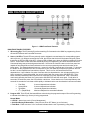
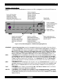
Figure 2 – ISM4 Rear Panel Features
ISM4 REAR PANEL FEATURES
10. IR Out. Four 2-circuit (mono) 3.5mm mini jacks connect to the IR Emitters for Sources 1-4.
11. IR RCVR (IR Receiver Port). One 3-circuit (stereo) 3.5mm mini jack connects to any Xantech IR Receiver
with a stereo mini plug. (291 Series or ‘Dash 30’ Type 480-30, 490-30 etc). This jack provides 12 VDC to the
ISM4 INSTALLATION & PROGRAMMING MANUAL
6
IR Receiver and receives IR signals from the receiver. IR signals input on this jack can control the ISM4 and
pass through to control the individual sources via the Source 1-4 IR Outputs.
12. IR Control. One 2-circuit (mono) 3.5mm mini jack connects to a normal Emitter Output on an IR repeater
system or IR Output on a system controller or A/V Receiver. IR signals input on this jack can control the ISM4
and pass through to control the individual sources via the Source 1-4 IR Outputs.
13. Power. 2.1mm coaxial jack connects to the included 12VDC 0.5A Power Supply (Xantech Part No
781ERGPS).
14. Expansion. One, 2-circuit (mono) 3.5mm mini jack connects to the Source 1 “Sense In” on a secondary ISM4
for system sync of three additional devices. When the Source 1 “Sense In” on the Primary ISM4 senses an
ON state (12VDC), this jack outputs 12VDC to the Source 1 “Sense In” on the Secondary ISM4 to indicate the
system ON state. The Source 2-4 devices on the Secondary ISM4 will then sync to the system as
programmed (turn ON). When the Source 1 “Sense In” on the Primary ISM4 senses an OFF state (0VDC),
this jack outputs 0VDC to the Source 1 “Sense In” on the Secondary ISM4 to indicate the system OFF state.
The Source 2-4 devices on the Secondary ISM4 will then sync to the system as programmed (turn OFF).
15. RS232. One, 3-circuit (stereo) mini jack connects to the RS232 Output on a system control device such as an
A/V Receiver, Whole House System Controller, etc. RS232 Commands Input on this port can trigger ISM4 IR
output for Source 1 Power (discrete ON/OFF, toggle ON/OFF) as well as Query Source Power State and
System info. This Port is bi-directional and will automatically send ISM4 System Status Info (Provided
Automatic Source Power State Notifications are enabled. Refer to the RS232 Control and Programming
section) when any Source state change has occurred or when queried by the RS232 control device.
16. Sense In. Four, 3-circuit (stereo) 3.5mm mini jacks connect to any of the Xantech SM Series Sensor
Modules. The ON/OFF state for each of Sources 1-4 will be detected by a Sensor Module appropriate for that
device, (i.e. SMVID01 Video Sensor for a DVD Player, SMVLT01 Voltage Sensor for a device with a 12V AC
or DC output such as an A/V Receiver or Whole-House System Controller). Each "Sense In" Jack is
associated with two IR Macros (ON/OFF) and a Source IR Output.
Before proceeding with this discussion, it is important to note that the Programming Procedure
imposes a requirement on the Source 1 (System Reference Device) macros that it does not impose on
any other macros. The requirement is as follows; on either the ON or the OFF Macros, the ISM4
assumes that the IR content (if programmed) of the first Command Structure (refer to the COMMAND
STRUCTURES section for a thorough description of Command Structures) be a Power Command. It
is left up to the programmer to ensure that this rule is strictly abided by. The problem is as follows; if
the System Reference device is manually (or by Remote Control) turned on, the resulting transition on
the System Reference Sense Input would be an Off-to-On transition. As a result, the ON Macro would
be launched. Given that a Toggle Power command is present in the macro, the Reference device
would immediately be turned off. Therefore, Toggle commands would not be permissible. The
programmer would be limited to discrete type of Power IR ONLY. Unfortunately, Discrete IR
commands are not as common as Toggle commands. To avoid this difficulty, the requirement stated
above was imposed. For any “Sense In” transition detected by the ISM4 on the Source 1 (System
Reference Input), the IR Content of the first Command Structure (containing a Power Command) will
be bypassed. If a Delay is programmed, however, it will be processed. The end result is that
regardless of whether or not a Toggle or a Discrete Power Command is present, the undesirable
situation described above would not take place. Hence, the more prevalent Toggle Power commands
can be utilized without any adverse effects at all. Please note that the IR content of Command
Structure 1 is only bypassed during execution of a “Sense In” initiated macro on the Source 1
(System Reference) Input. On every other case, the full macro will be executed. For instance, if the
trigger is a “Discrete Power On” RS232 (or IR) command, the entire macro would be executed. As a
result, having executed the first Command Structure, the System Reference Device will be turned on
as desired.
ISM4 INSTALLATION & PROGRAMMING MANUAL
7
When Source 1 (System Reference Device) is turned ON, the Sensor Module for that device will show an ON
state (+12V) to the Source 1 “Sense In”. The first task that the ISM4 will take is to launch the ON Macro for
Source 1. Based on the discussion above, the entire macro will be executed with the exception of the IR
content of Command Structure 1. The ISM4 will then ‘look’ at the ON/OFF state of Sources 2-4. If any is
sensed to be OFF, it will be turned ON utilizing its associated ON Macro. If at any time that Source 1 (System
Reference Device) is ON, any of the other Sources is sensed to be OFF, the ISM4 will output the ON Macro
associated with that device to sync it with the system. (System ON Mode)
When Source 1 (System Reference Device) is turned OFF, the Sensor Module for that device will show an
OFF state (0V) to the Source 1 “Sense In”. The first task that the ISM4 will take is to launch the OFF Macro
for Source 1. Based on the discussion above, the entire macro will be executed with the exception of the IR
content of Command Structure 1. The ISM4 will then ‘look’ at the ON/OFF state of Sources 2-4. If any is
sensed to be ON, it will be turned OFF utilizing its associated OFF Macro. If at any time that Source 1
(System Reference Device) is OFF, any of the other Sources is sensed to be ON, the ISM4 will output the
OFF Macro associated with that device to sync it with the system. (System OFF Mode)
Figure 3 – ISM4 Bottom Panel Features – Cover Plate Removed
ISM4 BOTTOM PANEL FEATURES
17. DIP Switch. Four Position DIP Switch sets associated Source 1-4 IR Output signal strength. ON = low output
(470 ohm resister) OFF = high output (100 ohm resister).
ISM4 INSTALLATION & PROGRAMMING MANUAL
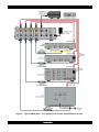
Figure 4 – Typical ISM4 System – AV Receiver Triggered Home Theater/IR Receiver Input
8
ISM4 INSTALLATION & PROGRAMMING MANUAL
Figure 5 – Typical ISM4 System – TV Triggered Home Theater System/IR Receiver Input
9
ISM4 INSTALLATION & PROGRAMMING MANUAL
Figure 6 – Typical ISM4 System – Multi-Zone Controller Triggered System/IR Control Input
10
ISM4 INSTALLATION & PROGRAMMING MANUAL
11
SYSTEM APPLICATIONS
The ISM4 is a versatile device with endless possible applications. For the purpose of this manual, two basic
applications will be described. One is a typical Home Theater application with the ISM4 managing system sync for
an A/V Receiver and three source components. The other is a multi-zone application integrating the ISM4 with a
multi-zone controller that does not provide intelligent source power management to keep the sources in sync with
whole-house system status.
HOME THEATER SYSTEM (Figure 4)
In this configuration, all system components can either be controlled directly with a programmed system remote or
exclusively through an IR Receiver connected to the ISM4. In this configuration the A/V Receiver will be turned
ON/OFF with the remote (or receiver front panel power button). When the receiver turns ON, the switched AC
Outlet on the rear panel will also turn ON, energizing the connected 12V Power Supply. The SMVLT01 Voltage
Sensor will detect the change of state, (in this case from OFF to ON) and show a control voltage to the Source 1
“Sense In” on the ISM4. (ISM4 System Status is always referenced to the device sensed by the Source 1 “Sense
In”). The first task that the ISM4 will take in response to the Off-to-On transition is to execute the Power ON Macro
associated with the Source 1 “Sense In” input. Recall that in executing this macro (launched by a Source 1
“Sense In” trigger) the IR content of the first Command Structure will be bypassed. Refer to the Sense In section
for further information. The ISM4 will then ‘look’ at the other Source Sense Inputs and if they are OFF (no sensor
control voltage), the ISM4 will output the Power ON Macros associated with each source to turn them ON. THE
SYSTEM POWER ON COMMAND IN THE REMOTE SHOULD ONLY CONTROL THE A/V RECEIVER. The
ISM4 will control the other devices for turn ON and sync. Additionally, each Source Power ON Macro can be
programmed for up to five IR commands (and associated delays). If the sources are to be set to particular settings
at turn on, these commands will be issued by the ISM4, and NOT the system remote. If at any time that the
System Reference Device (A/V Receiver) is ON, any of the other sources turn off, for any reason, the ISM4 will
sense the variation from system sync (source OFF vs system ON), and the ISM4 will automatically issue the
Power ON Macro for the device that is out of sync.
IR commands from the remote can be passed through the ISM4 via the IR Receiver to the emitters, allowing the
system components to be hidden in a cabinet or closet, as long as the IR Receiver is positioned in ‘line-of-sight’ to
the system remote. The system components can also be controlled directly from the remote, but no power
commands should be issued from the remote other than for the A/V Receiver.
Turning the system OFF is the opposite process. When the A/V Receiver is turned OFF with the system remote
(or receiver front panel button), the switched AC outlet on the rear panel will turn OFF, de-energizing the 12V
power supply. The SMVLT01 Voltage Sensor will detect the change of state, (ON to OFF), and cut the control
voltage to the Source 1 “Sense In”. The first task that the ISM4 will take in response to the On-to-Off transition is
to execute the Power Off Macro associated with the Source 1 “Sense In” input. Recall that in executing this
macro (launched by a Source 1 “Sense In” trigger) the IR content of the first Command Structure will be
bypassed. Refer to the Sense In section for further information. The ISM4 will then ‘look’ at the other Source
Sense Inputs and if they are ON, (sensor control voltage) the ISM4 will output the Power OFF Macros associated
with each source to turn them OFF. THE SYSTEM POWER OFF COMMAND IN THE REMOTE SHOULD ONLY
CONTROL THE A/V RECEIVER. The ISM4 will control the other devices.
Other Applications
Using the same basic scheme described above, there are many options as to what device will be the System
Reference Device. In some cases it will be most intuitive to have a TV, Video Monitor or projector be the System
Reference Device. (See Figure 5 in this manual and the ISM4 Quick Start Guide for configuration and
programming instructions) Any time the TV is turned ON, by incorporating a SMVID01 Video Sensor on a TV
Video Output, the ISM4 will execute ON Macros to turn ON an A/V Receiver, DVD Player, Cable Box and Satellite
Receiver, for example. Another possibility would be to have a Video Game trigger the system. By making the
Video Game the System Reference Device, any time the Video Game is turned ON, the ISM4 will activate and
sync all appropriate devices for extreme gaming. The possibilities are endless. When incorporating an ISM4 into a
system, ask the question: “What device or appliance do I want to use to trigger other devices or appliances?”
ISM4 INSTALLATION & PROGRAMMING MANUAL
12
MULTI-ZONE A/V SYSTEM (Figure 6)
The multi-zone configuration provides automatic power management (system sync) when used with a multi-zone
system controller that does not feature intelligent source power management. Some multi-zone controllers come
equipped with proper, reliable system sync management capabilities (Xantech MRC44/88). Some provide
methods that guess at system status, that is, they will output ON/OFF commands in conjunction with the controller
status, but do not really know if the source components are ON or OFF, while others provide no method of power
management at all. ISM4 is the perfect complement to these last two types of controllers.
In this configuration, system commands are initiated in the remote zones via keypads and/or IR Receivers.
Typically, when the first zone on a multi-zone controller is activated, the controller will turn ON and in most cases,
also turn on a Common 12V Control Output. With this Control Out connected to a SMVLT01 Voltage Sensor, the
SMVLT01 Voltage Sensor will detect the change of state, (in this case from OFF to ON) and show a control
voltage to the Source 1 “Sense In” on the ISM4. (ISM4 System Status is always referenced to the device sensed
by the Source 1 “Sense In”.) The ISM4 will then ‘look’ at the other Source Sense Inputs and if they are OFF (no
sensor control voltage), the ISM4 will output the Power ON Macros associated with each source to turn them ON.
KEYPADS AND ZONE REMOTES SHOULD BE PROGRAMMED ONLY TO TURN THE LOCAL ZONE ON AND
SHOULD NOT INCLUDE SOURCE POWER COMMANDS IN “ON MACROS”. The ISM4 will control the other
devices for turn ON. Additionally, each Source Power ON Macro can be programmed for up to five IR commands
(and associated delays) so if the sources are to be set to particular settings at turn on these commands will be
issued by the ISM4, NOT the multi-zone controller. If at any time that the System Reference Device (multi-zone
controller) is ON, any of the other sources turn off, for any reason, the ISM4 will sense the variation from system
sync (source OFF vs system ON), and the ISM4 will automatically issue the Power ON Macro for the device out of
sync.
In a typical multi-zone system, the connected keypads and/or IR Receivers will issue zone/system commands
directly to the system controller (Zone ON/OFF, Volume, Source Select, etc). (The ISM4 does not play any part in
controlling the multi-zone controller, only the source components.) Some multi-zone systems issue IR commands
for source control from the keypads or pass through IR commands from IR Receivers and zone remotes, while
others generate IR commands initiated by keypad button presses or ‘IR trigger commands’. In any case, the IR
commands that are output from the controller must be routed from the Common IR Output on the multi-zone
controller and then to the IR Control In on the ISM4. The source IR commands will then pass through the ISM4 to
the Source IR Outs. This means the IR emitters for the sources will be connected to the ISM4, NOT the multizone controller. This allows use of one IR emitter per source rather than having one from the multi-zone controller
and one from the ISM4. System operation will be normal and the IR routing will be ‘invisible’ to the user. (This
makes the ISM4 a perfect ad-on for exiting systems with sync issues.) One important note: The ISM4 IR passthrough is not routed so systems with multiple same brand/same model devices will not have selective control for
tuning SAT 1 or SAT 2 unless multiple IR code groups are available.
Turning the system OFF is the opposite process. Typically, when the last zone on the multi-zone controller is
turned OFF the Common 12V Control Out will also turn OFF. The SMVLT01 Voltage Sensor will detect the
change of state, (ON to OFF), and cut the control voltage to the Source 1 “Sense In”. The ISM4 will then ‘look’ at
the other Source Sense Inputs and if they are ON, (sensor control voltage) the ISM4 will output the Power OFF
Macros associated with each source to turn them OFF. KEYPADS AND ZONE REMOTES SHOULD BE
PROGRAMMED ONLY TO TURN THE LOCAL ZONE OFF AND SHOULD NOT INCLUDE SOURCE POWER
COMMANDS IN OFF MACROS. The ISM4 will control the other devices.
ISM4 INSTALLATION & PROGRAMMING MANUAL
13
INSTALLATION
The ISM4 should be installed in the same general location as the system A/V components (A/V Receiver, MultiZone Controller, DVD, SAT, etc). Xantech SM Series Sensor Cables are approximately 6 feet in length and
Xantech IR Emitter wires are approximately 10 feet in length, so plan the ISM4 location relative to the other
equipment accordingly. The ISM4 does not generate any critical amount of heat and does not need any special
consideration in terms of ventilation but proper precautions should always be taken to assure the free flow of air
through and around system components to avoid damage. The ISM4 can be placed on a shelf in an equipment
rack or closet or placed directly on top of a system device. It is suggested however, that the ISM4 not be placed
directly on top of a device that generates high levels of heat to protect the ISM4 circuitry and longevity.
CONNECTIONS
ISM4 connections are fairly simple. The most important factor is keeping the wiring consistent by source. That
means be sure the device connected to the Source 1 “Sense In” is the same device attached to the Source 1 IR
Emitter. Labeling the Sensor and Emitter Wires as Source 1, 2, 3, 4 or by specific brand/device (Denon Receiver,
Toshiba DVD, etc) will help in avoiding connection errors and assist in troubleshooting, if necessary. There are
many possible connection schemes for ISM4 controlled systems. For the purpose of the following discussions, the
systems in Figures 4 and 6 will be used. Also note that Xantech manufactures a full line of Sensor Modules
including: Audio (SMAUD01), Video (SMVID01), Magnetic/Current (SMMAG01), LED/Light (SMLIT01), Contact
Closure (SMCC01) and Voltage (SMVLT01) for additional application flexibility of the ISM4.
HOME THEATER SYSTEM (Figure 4)
ISM4
1. Plug the included 12VDC Power Supply 2.1mm coaxial plug into the Power Jack on the ISM4 Rear Panel.
2. Plug the Power Supply into an unswitched AC Outlet.
Source 1 (A/V Receiver)
1. Cut the plug off the end of an unregulated 12VDC Power Supply. (An unregulated power supply’s decay
time, 12V to 0V, is faster than a regulated supply, netting faster system response.) Strip approximately 1/4” off
the jacket and twist the strands so that there are no loose ends that can cause shorts.
2. Connect the stripped ends to the appropriate terminals on the SMVLT01 Sensor. Maintain proper polarity,
typically white stripe (+12V) to the ‘+’ terminal, black wire (GND) to the ‘-‘ terminal.
3. Plug the power supply into a switched AC outlet on the A/V Receiver.
4. Plug the SMVLT01 3.5mm mini plug into the ISM4 Source 1 “Sense In” Jack.
5. Turn the A/V Receiver ON. The SMVLT01 Status LED should illuminate red. (The Source 1 Status LED on
the ISM4 Front Panel should also illuminate solid green. For now, disregard any other front panel LED
activity.)
6. Turn the A/V Receiver OFF. The SMVLT01 Status LED should turn off. If it does not turn off, adjust the
sensitivity to the point where the Status LED turns off. (The Source 1 Status LED on the ISM4 Front Panel
should also turn off. For now, disregard any other front panel LED activity.)
7. Remove the protective backing from an IR Emitter head. Carefully attach the emitter over the IR eye of the
A/V Receiver. If the eye is not obvious, shine a small flashlight into the faceplate to locate it or refer to the
product manual.
8. Carefully pull the emitter wire to the back of the A/V Receiver and over to where the ISM4 is located. Be
careful not to pinch the wire between components.
9. Plug the Emitter 3.5mm mini plug into the ISM4 Source 1 “IR Out “Jack.
10. Label the sensor and emitter wires for reference.
Source 2 (DVD Player)
1. Using a shielded male to male RCA-RCA video cable (Composite Video Cable) with gold ends, connect the
Composite Video Output of the DVD Player to the SMVID01 RCA sensor head.
ISM4 INSTALLATION & PROGRAMMING MANUAL
14
2. Either plug the sensor head directly into the A/V Receiver DVD Composite Video Input or connect a
shielded female to male RCA-RCA cable with gold ends to the sensor head and then to the AV Receiver
DVD Composite Video Input.
3. Plug the SMVID01 3.5mm mini plug into the ISM4 Source 2 “Sense In” Jack.
4. Turn the DVD Player ON. The SMVID01 Status LED should illuminate red. (The Source 2 Status LED on the
ISM4 Front Panel should also illuminate green. For now, disregard any other front panel LED activity.)
5. Turn the DVD Player OFF. The SMVID01 Status LED should turn off. If it does not turn off, adjust the
sensitivity to the point where the Status LED turns off. (The Source 2 Status LED on the ISM4 Front Panel
should also turn off. For now, disregard any other front panel LED activity.)
NOTE: Some devices have a constant signal output on the composite video output jack (many cable boxes
and other devices) and will not be compatible with video sensing. If adjusting the sensitivity on the SMVID01
with the DVD player (or other device) does not turn the Status LED OFF, another sensing method must be
used, such as a switched outlet on a cable box as shown in Figure 4.
6. Remove the protective backing from an IR Emitter head. Carefully attach the emitter over the IR eye of the
DVD Player. If the eye is not obvious, shine a small flashlight into the faceplate to locate it or refer to the
product manual.
7. Carefully pull the emitter wire to the back of the DVD Player and over to where the ISM4 is located. Be
careful not to pinch the wire between components or block the disc drawer.
8. Plug the Emitter 3.5mm mini plug into the ISM4 Source 2 “IR Out “Jack.
9. Label the sensor and emitter wires for reference.
Source 3 (Cable Box)
Follow the instructions for Source 1 (A/V Receiver), for voltage sensing. The switched outlet on most cable
boxes must be configured in the Cable Box Setup Menu. Be sure the AC Convenience Outlet is set to:
Switched.
Source 4 (Video Recorder)
Follow the instructions for Source 2 (DVD Player), for video sensing.
IR Receiver
1. Plug a Xantech 291 Series or ‘Dash 30’ Type IR Receiver (IR Receivers with an attached stereo 3.5mm mini
plug cable), into the IR Receiver Jack on the ISM4 Rear Panel. Position the IR Receiver as appropriate for
‘line-of-sight’ to the where the system remote will typically be used. This will allow IR control of the ISM4 and
pass through of IR commands from the system remote to the source devices.
MULTI-ZONE SYSTEM (Figure 6)
ISM4
1. Plug the included 12VDC Power Supply 2.1mm coaxial plug into the Power Jack on the ISM4 Rear Panel.
2. Plug the Power Supply into an unswitched AC Outlet.
Source 1 (Multi-Zone Controller)
1. Using a Xantech 5-Foot Mini Plug Cable, (3.5mm mini plug to two stripped/tinned leads, Xantech Part No
06015900), plug the mini plug end into the Common 12V Control Out on the multi-zone controller.
2. Connect the stripped/tinned ends to the appropriate terminals on the SMVLT01 Sensor. Maintain proper
polarity, typically white stripe (+12V) to the ‘+’ terminal, black wire (GND) to the ‘-‘ terminal. (See
manufacturer’s product manual to verify the pin-out of the Common 12V Out Jack.)
3. Plug the SMVLT01 3.5mm mini plug into the ISM4 Source 1 “Sense In” Jack.
4. Turn a Zone on the multi-zone controller ON. The SMVLT01 Status LED should illuminate red. (The
Source 1 Status LED on the ISM4 Front Panel should also illuminate solid green. For now, disregard any
other front panel LED activity.)
5. Turn the multi-zone controller OFF. The SMVLT01 Status LED should turn off. If it does not turn off, adjust
the sensitivity to the point where the Status LED turns off. (The Source 1 Status LED on the ISM4 Front
Panel should also turn off. For now, disregard any other front panel LED activity.)
ISM4 INSTALLATION & PROGRAMMING MANUAL
15
6. Using a Xantech 10-Foot Mono Cable (Xantech Part No 06017450) connect the Common “IR Out “ on the
multi-zone controller to the IR Control Jack on the ISM4 Rear Panel. This will allow IR control of the ISM4
and pass through of IR commands from the multi-zone controller to the source devices.
7. There is no required emitter connection to Source 1 in this application.
8. Label the Sensor and Common IR wires for reference.
Source 2 (DVD Player)
10. Using a shielded male to male RCA-RCA video cable (Composite Video Cable) with gold ends, connect the
Composite Video Output of the DVD Player to the SMVID01 RCA sensor head.
11. Either plug the sensor head directly into the multi-zone controller DVD Composite Video Input or connect
a shielded female to male RCA-RCA cable with gold ends to the sensor head and then to the multi-zone
controller DVD Composite Video Input.
12. Plug the SMVID01 3.5mm mini plug into the ISM4 Source 2 “Sense In” Jack.
13. Turn the DVD Player ON. The SMVID01 Status LED should illuminate red. (The Source 2 Status LED on the
ISM4 Front Panel should also illuminate solid green. For now, disregard any other front panel LED activity.)
14. Turn the DVD Player OFF. The SMVID01 Status LED should turn off. If it does not turn off, adjust the
sensitivity to the point where the Status LED turns off. (The Source 2 Status LED on the ISM4 Front Panel
should also turn off. For now, disregard any other front panel LED activity.)
NOTE: Some devices have a constant signal output on the composite video output jack (many cable boxes
and other devices) and are not compatible with video sensing. If adjusting the sensitivity on the SMVID01 with
the DVD player (or other device) OFF does not turn the Status LED OFF, another sensing method must be
used, such as a switched outlet on a cable box as shown in Figure 6.
15. Remove the protective backing from an IR Emitter head. Carefully attach the emitter over the IR eye of the
DVD Player. If the eye is not obvious, shine a small flashlight into the faceplate to locate it or refer to the
product manual.
16. Carefully pull the emitter wire to the back of the DVD Player and over to where the ISM4 is located. Be
careful not to pinch the wire between components or block the disc drawer.
17. Plug the Emitter 3.5mm mini plug into the ISM4 Source 2 “IR Out “Jack.
18. Label the sensor and emitter wires for reference.
Source 3 (Cable Box)
Follow the instructions for Source 1 (A/V Receiver), for voltage sensing. The switched outlet on most cable
boxes must be configured in the Cable Box Setup Menu. Be sure the AC Convenience Outlet is set to:
Switched.
Source 4 (Video Recorder)
Follow the instructions for Source 2 (DVD Player), for video sensing.
ISM4 INSTALLATION & PROGRAMMING MANUAL
16
OTHER CONNECTIONS
RS232
This Port connects to the RS232 Output on a system control device such as an A/V Receiver, Multi-Zone
Controller, Touch Panel, etc. RS232 Commands input on this port can trigger ISM4 IR output for Source 1 Power
(discrete ON/OFF, toggle ON/OFF), Query Source Power State (all sources) and System Info. This Port is bidirectional and will automatically send ISM4 System Status Info when any Source state change has occurred
(provided that the Automatic Source Power State Notification feature is enabled) or when queried by the RS232
control device. See Section: RS232 for additional information.
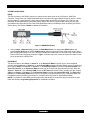
Figure 7 ISM4 RS232 Pinout
1. Using a stereo 3.5mm mini plug, connect the ISM4 RS232 Port to an appropriate RS232 Port on the
system control device to be used for RS232 control. Adapt the stereo mini-plug cable to the control device
port as appropriate (DB-9, RJ45, etc.) Xantech manufactures a Male DB9 to 3.5mm Mini Plug Cable (Xantech
Part No 05913780) configured as shown in Figure 7. Please refer to the control device documentation for the
pinout of that device’s RS232 Port.
EXPANSION
This jack connects to the Source 1 “Sense In” on an Expansion ISM4 for system sync of three additional
devices. When the Source 1 “Sense In” on the Primary ISM4 senses an ON state (Sensor Control Voltage), this
jack outputs 12VDC to the Source 1 “Sense In” on the Expansion ISM4 to indicate the System ON state. The
Source 2-4 devices on the Expansion ISM4 will then sync to the system as programmed (turn ON). When the
Source 1 “Sense In” on the Primary ISM4 senses an OFF state (No Sensor Control Voltage), this jack outputs
0VDC to the Source 1 “Sense In” on the Expansion ISM4 to indicate the System OFF state. The Source 2-4
devices on the Secondary ISM4 will then sync to the system as programmed (turn OFF). Additional ISM4s can
be added as needed increasing the number of ‘managed’ devices by three for each additional ISM4.
NOTE: For Expansion, each ISM4 must be programmed individually for the specific devices connected to each
ISM4. See Section: Programming/Expansion for additional Information.
ISM4 INSTALLATION & PROGRAMMING MANUAL
17
Figure 8 ISM4 Expansion Connections
1. Using a 1-Foot Mono Cable (Xantech Part No 6017400), connect the Expansion Jack on the Primary ISM4
to the Source 1 “Sense In” on the First Expansion ISM4.
2. If using additional ISM4s, repeat Step 1 for each additional ISM4 as shown in Figure 8.
3. Connect the included Power Supplies, one to each ISM4.
4. Connect the Sensors and Emitters as described the Sections: Connections/Home Theater System or
Connections/Multi-Zone System.
NOTE 1: The Source 1 “Sense In” on the ISM4 Expansion units is used for System Status as referenced
to the System Reference Device. There is no required IR Emitter connection to the Source 1 IR Outs on
the ISM4 Expansion units.
NOTE 2: If using the Expanded application with a multi-zone controller, there would be no required IR
Emitter connection to the Primary ISM4 Source 1 “IR Out “as shown in Figure 8.
18
ISM4 INSTALLATION & PROGRAMMING MANUAL
PROGRAMMING
Programming the ISM4 is similar to manually programming a learning remote. All IR commands are programmed
(learned) directly to the ISM4 using the original equipment remotes. There is no PC or programming software
requirement. If the ISM4 is going to be set up to automatically ‘manage’ system devices (Sources 2-4) based
solely upon the status (ON/OFF) of the System Reference Device (Source 1 - A/V Receiver, Multi-Zone
Controller, etc), with the original remotes in-hand, the first step is to plan the Source Macros.
One of the ISM4 control options has the ISM4 react to Xantech RC68 IR Commands for Discrete Power ON/OFF
or Toggle Power ON/OFF control of Source 1. The ‘discrete’ option allows programming discrete System ON/OFF
‘Trigger’ Commands to a system remote or control device when the System Reference Device does not have
discrete ON/OFF Commands. This will provide separate System ON/OFF buttons and help the user avoid
inadvertently turning the system ON/OFF. The ‘toggle’ option allows utilizing a single button for system ON/OFF
from a system remote or control device. If utilizing this feature, a Xantech RC68X will also be required. (Older
models: RC68 and RC68+ are also compatible.) See Section: Programming RC68 ON/OFF Trigger Commands
for additional information.
SOURCE ON/OFF MACROS
The ISM4 allows programming one ON and one OFF Macro per Source. Each of these Macros can contain up to
five sets of IR Commands and Delays called Command Structures. Different Front Panel LED prompts indicate
which Macro (ON/OFF) for which Source (1-4) and which step or ‘Command Structure’ (1-5) is being
programmed.
COMMAND STRUCTURES
A Command Structure is the combination of an IR command and an associated Delay within a given Source ON
or OFF Macro. Each ON or OFF Macro can contain up to five Command Structures. A Command Structure has
an associated Delay even if the delay value is 0 seconds. All five Command Structures do not need to be
programmed within an ON or OFF Macro. If only the ON or OFF command is to be issued with no further setup
(input, play, etc) to the controlled device(s) then only the ON or OFF Command need be programmed.
Command Structure
1
2
3
4
5
SOURCES 1- 4
Source ON Macro
IR
Delay
IR
Delay
IR
Delay
IR
Delay
IR
Delay
Source OFF Macro
IR
Delay
IR
Delay
IR
Delay
IR
Delay
IR
Delay
Table 1 Command Structures
NAVIGATING AND EDITING MACROS
The six Front Panel Buttons each have multiple functions, depending upon the ISM4 Mode. There is a detailed
explanation of those functions within the different modes in the Appendix. An understanding of the button
presses will help make the programming process easier. For the actual programming instructions, proceed to
Section: Programming Macros, immediately following.
19
ISM4 INSTALLATION & PROGRAMMING MANUAL
PROGRAMMING MACROS
The first step in programming the ISM4 is to fill out the Macro Programming Table. This will help keep track of
what device is being programmed for which command with how much delay in which Command Structure within
the Source ON or OFF Macro being programmed. Fill out the Table as appropriate for the ISM4 being
programmed. It might be advantageous to keep a backup copy of of the table for later use.
MACRO PROGRAMMING TABLE
MACRO PROGRAMMING TABLE
Command
Structure
Source 1
Source 2
Source 3
Source 4
Brand 1
Device 1
ON
OFF
ON
OFF
ON
OFF
ON
OFF
ON
OFF
ON
OFF
ON
OFF
ON
OFF
ON
OFF
ON
OFF
ON
OFF
ON
OFF
ON
OFF
ON
OFF
ON
OFF
ON
OFF
ON
OFF
ON
OFF
ON
OFF
ON
OFF
IR Command
Delay (Sec)
Brand 2
Device 2
IR Command
Delay (Sec)
Brand 3
Device 3
Command
Delay (Sec)
Brand 4
Device 4
IR Command
Delay (Sec)
Brand 5
Device 5
IR Command
Delay (Sec)
ISM4 INSTALLATION & PROGRAMMING MANUAL
20
With the ISM4 powered up and with the IR Emitters attached to the devices to be controlled, program the ISM4 as
follows:
NOTE: Unless instructed to press a button for a specific duration a button press should be at most one full
second.
IMPORTANT NOTE: If programming the ISM4 so the System Reference Device (Source 1) will be turned
ON and OFF with its native remote or other system controller, the programmer must ensure that the Power
command (if present) be placed in Command Structure number 1. This applies to both the ON and OFF macros.
This requirement is imposed on Source 1 ONLY. Refer to the “Sense In” section for further details.
If there are other ‘setup’ commands to be executed as part of the Source 1 ON Macro, (Input, Surround Mode,
Tuner Preset, etc), simply program a delay long enough to allow Source 1 to power up and respond to additional
IR commands. (Step 13 below). Recall that the Delay will be executed regardless of whether or not a Power
Command is present in Command Structure 1.
If any of Sources 2-4 will have ‘setup’ commands included in their ON Macros, be sure to program a delay in the
Source ON Macro, Command Structure 1 that is long enough to allow those Sources to power up and be ready to
respond to additional IR commands.
The following sections mention the ISM4’s time dependent push button function blink patterns. For a detailed
discussion refer to section “Source 1-4 LED’s”. These blink patterns were added to transfer the time keeping
burden away from the programmer and onto the ISM4.
Learn IR
1. Press the Sequence Button for 2 seconds (Indicated by the first blink of the Active Source LED) to enter Edit
Mode. The ISM4 will default to the Source 1 ON Macro. (Source 1 and Program LED’s sold green.)
2. Press the Sequence Button to enter IR Learn Mode for Source 1 ON Macro Command Structure 1. The
Source 1 LED will flash for about 5 seconds. This is the amount of time allowed to teach an IR Command.
3. Position the IR Remote for the System Reference Device (Source 1) directly in front of the IR Learn Window
on the ISM4 (within an inch) and press and hold the ON or Power Button on the remote until the Program
LED flashes green three times. If the Program LED flashes red three times, proceed to Step 9.
4. Press the Test Button and confirm the function of the learned command on Source 1.
5. If Source 1 responded properly to the learned command, press Sequence again to save the command. The
Program LED will flash once. The ISM4 will automatically return to EDIT Mode upon save. To return to Edit
Mode without saving, press the PREV Button. Proceed to Step 11 or 13, as appropriate.
6. If Source 1 did not respond properly to the learned command, press Delete. The ISM4 will automatically go
into IR Learn Mode for the current Command Structure. (Source 1 ON Macro; Command Structure 1)
7. Repeat Steps 3-6 as necessary until the command is learned, tested, confirmed and saved.
8. To add a Delay to Command Structure 1, proceed to Step 13.
IR Learn Error
9. If the Program LED flashed red three times during IR Learn, that indicates a learn error. Press Delete to
remove the bad command from memory.
10. Repeat Steps 2-6 as necessary until the command is learned, tested, confirmed and saved.
No Delay – with additional Command Structures in the Macro
11. If there is no delay required for Command Structure 1, and there is at least one more Command Structure
in the Macro, press "Next" for one second. The Source 1 LED will flash twice indicating the ISM4 is ready to
Learn the IR Command for Command Structure 2. If the ISM4 is pointing to Command Structure 3, the
Source 1 Led will blink 3 times. It will blink 4 times if pointing to Command Structure number 4 and 5 times if
pointing to Command Structure number 5.
12. Repeat Steps 2-9 as necessary until the IR Command for Command Structure 2 is learned, tested,
confirmed and saved.
ISM4 INSTALLATION & PROGRAMMING MANUAL
21
Delay – with additional Command Structures in the Macro
13. To add a delay after the IR Command in Command Structure 1, after Step 5, press the Delay Button. The
ISM4 will respond by entering DELAY Learn Mode and the Program LED will flash once.
14. Press the Next Button once for each second of Delay to be added to the Command Structure. Press the
Prev Button once for each second of Delay to be subtracted.
NOTE: The first press of the Next Button will add one second of delay. Each additional press will add one
second up to 60 seconds after which the timer will reset to 0 seconds. The first press of the Prev Button will
add 60 seconds of delay. Each additional press will subtract one second down to 0 seconds after which the
timer will reset to 60 seconds.
No Delay – no additional Command Structures in the Macro
15. If there are no additional Command Structures in the Source 1 ON Macro, press "Next" for 2 seconds
(Indicated by the first blink of the Active Source LED). The ISM4 will shift to the Source 1 OFF Macro,
Command Structure 1. (Source LED solid green, Program LED solid red.)
NOTE: A 2 second press of the Prev Button (Indicated by the first blink of the Active Source LED) will shift
programming to the previous Macro. (i.e. a 2 second press of the Prev Button while in Source 1 ON Edit
Mode, will shift Edit Mode to the Source 4 OFF Macro. (Source 4 LED solid green, Program LED orange.)
Test Macro
16. When all Command Structures within a Source ON or OFF Macro have been programmed, tested and
saved, the complete Macro can be tested by pressing the Test Button.
NOTE 1: If the IR Commands and Delays within the Command Structures were not properly saved, the Macro
cannot be tested and the Program LED will flash red to indicate error.
NOTE 2: To Test a Macro starting from Normal Operation Mode, Press Sequence for 2 seconds (Indicated by
the first blink of the Active Source LED) to enter Edit Mode, (Source 1 and Program LED’s green), Navigate to
the Macro to be tested (2 second press of Prev or Next) and then press the Test Button.
Program Remaining Macros
17. Navigate to the next Source ON or OFF Macro to be programmed. From the Source 1 ON Macro, press the
Next Button for 2 seconds (Indicated by the first blink of the Active Source LED). The ISM4 will shift to the
Source 1 OFF Macro; Command Structure 1. (Source LED solid green, Program LED solid orange.)
NOTE: A 2 second press of the Prev Button (Indicated by the first blink of the Active Source LED) will shift
programming to the previous Macro. (i.e. a 2 second press of the Prev Button while in Source 1 ON Edit
Mode, will shift Edit Mode to the Source 4 OFF Macro. (Source 4 LED solid green, Program LED red.)
18. Repeat Steps 2-17 above until all Source ON and OFF Macros have been programmed, tested and saved. It
is vitally important to program both the Source ON and OFF Macros. The ISM4 will not function properly if
both sets of Macros have not been programmed.
Exit Edit Mode
19. To exit Edit Mode, at any time during Edit Mode, press the Prev Button for 10 seconds (Indicated by the
third blink of the Active Source LED). The ISM4 will return to Normal Operating Mode.
Test ISM4 (All Macros)
NOTE: All system devices and components must be properly setup and connected to test ISM4 Macro
Programming. Be sure all Sensors are connected to the appropriate device and Source Sense Inputs on the
ISM4, and be sure all IR Emitters are connected to the appropriate Source “IR Out “on the ISM4 and attached to
the correct device over the IR eye for that device.
20. With all Sources OFF, turn the System Reference Device (Source 1) ON. All Sources should turn ON and
any additional setup programming (source select, play, etc) should execute as programmed. If any functions
were ‘missed’, test the individual ON Macro for that Source. Re-learn IR Commands and adjust delays as
necessary until the system powers up correctly.
21. Repeat Step 20 for System OFF. (Turn the System Reference Device, Source 1, OFF).
ISM4 INSTALLATION & PROGRAMMING MANUAL
22
PROGRAMMING RC68 ON/OFF TRIGGER COMMANDS
As noted at the beginning of the Programming Section, one of the ISM4 control options has the ISM4 react to
Xantech RC68 IR Commands for Discrete Power ON/OFF or Toggle Power ON/OFF control of Source 1. When
using the RC68 Commands, when the ON Button on the system remote is pressed, it will issue the RC68 ON
Command. The ISM4 will ‘see’ the RC68 ON Command and output the native Source 1 device Power or ON
command via the Source 1 IR Emitter, (if Source 1 is OFF). In this application, the Power or ON Command for the
System Reference Device (Source 1) was pre-programmed into the ISM4. (The same programming and
functionality would then also be true for programming the RC68 OFF Command. RC68 Toggle Power is
programmed in a similar manner.) To Program RC68 ON/OFF Trigger Commands:
RC68 Discrete ON/OFF Trigger Command Programming
Program
1. Program the ISM4 Source 1 ON Macro as described in the Programming Macros Section, programming
the IR Command from the native remote for the System Reference Device, (Source 1) Power or ON
Command to the Source 1 ON Macro, Command Structure 1. IF THE POWER OR ON COMMAND FOR
SOURCE 1 IS NOT PROGRAMMED TO THIS LOCATION, THE ISM4 WILL NOT FUNCTION PROPERLY.
2. Program the IR Command from the native remote for the System Reference Device, (Source 1) Power or
OFF Command to the Source 1 OFF Macro, Command Structure 1. IF THE POWER OR OFF COMMAND
FOR SOURCE 1 IS NOT PROGRAMMED TO THIS LOCATION, THE ISM4 WILL NOT FUNCTION
PROPERLY.
3. Set the RC68 Remote to Code Group 10.
4. Teach the RC68 Command from Button 00 to the System Remote Button that will be used to turn the
system ON.
5. Teach the RC68 Command from Button 40 to the System Remote Button that will be used to turn the
system OFF.
Test ON
6. With all sources, sensors and emitters connected to the ISM4, and with all sources turned OFF, test the
system by pointing the System Remote toward the ISM4 or connected IR Receiver and press the button
with the RC68 ON Command. The System Reference Device (Source 1) and Sources 2-4 should all turn
ON.
Test OFF
7. With all sources turned ON, test the system by pointing the System Remote toward the ISM4 or connected
IR Receiver and press the button with the RC68 OFF Command. The System Reference Device (Source
1) and Sources 2-4 should all turn OFF.
8. If any functions were ‘missed’, test the individual ON or OFF Macro for that Source. Re-learn IR Commands
and adjust delays as necessary until the system powers up correctly.
RC68 Toggle ON/OFF Trigger Command Programming
Program
1. Program the ISM4 Source 1 ON Macro as described in the Programming Macros Section, programming
the IR Command from the native remote for the System Reference Device, (Source 1) ON Command to
the Source 1 ON Macro, Command Structure 1. IF THE ON COMMAND FOR SOURCE 1 IS NOT
PROGRAMMED TO THIS LOCATION, THE ISM4 WILL NOT FUNCTION PROPERLY.
2. Program the IR Command from the native remote for the System Reference Device, (Source 1) OFF
Command to the Source 1 OFF Macro, Command Structure 1. IF THE OFF COMMAND FOR SOURCE 1
IS NOT PROGRAMMED TO THIS LOCATION, THE ISM4 WILL NOT FUNCTION PROPERLY.
3. Set the RC68 Remote to Code Group 10 (One, Zero).
4. Teach the RC68 Command from Button 80 to the System Remote Button that will be used to turn the
system ON/OFF.
Test ON
5. With all sources, sensors and emitters connected to the ISM4, and with all sources turned OFF, test the
system by pointing the System Remote toward the ISM4 or connected IR Receiver and press the button
ISM4 INSTALLATION & PROGRAMMING MANUAL
23
with the RC68 Toggle Command. The System Reference Device (Source 1) and Sources 2-4 should all
turn ON.
Test OFF
6. With all sources turned ON, test the system by pointing the System Remote toward the ISM4 or connected
IR Receiver and press the button with the RC68 Toggle Command. The System Reference Device
(Source 1) and Sources 2-4 should all turn OFF.
7. If any functions were ‘missed’, test the individual ON or OFF Macro for that Source. Re-learn IR Commands
and adjust delays as necessary until the system powers up correctly.
24
ISM4 INSTALLATION & PROGRAMMING MANUAL
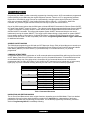
RS232 CONTROL AND PROGRAMMING
The ISM4 can be controlled via RS232 to allow power management of the devices controlled by the ISM4 from a
PC or appropriately capable system controller. It is important to note that the RS232 capability only allows for
Discrete ON/OFF, Toggle ON/OFF as well as Status and System Information. The RS232 Discrete ON/OFF
and Toggle Commands allow turning the System Reference Device (Source 1) ON/OFF. IT DOES NOT
ALLOW RS232 CONTROL OF ANY OTHER SOURCES OR FUNCTIONS.
The Status feature provides queried or automatic feedback of Source ON/OFF Status. Queried feedback will
provide ON/OFF Status of Sources 1-4 in the form of ASCII Text Strings when asked by a control device.
Automatic Source Power State Notifications are provided as ASCII Text Strings anytime there is a change in
Source ON/OFF Status. This feature (Auto) can be turned on or off as appropriate for a given application. By
default, this feature is disabled.
ISM4 System Information can also be queried for product information such as Device, Hardware and Firmware
Rev, should it be relevant in troubleshooting. Xantech Technical Support personnel may request this information
in a problematic application.
To respond to RS232 Commands, the ISM4 must be properly connected via the RS232 jack on the Rear Panel as
described in Section: Other Connections/RS232.
RS232 Com Port Settings
Use the following Table to configure the RS232 output of the device controlling the ISM4:
Baud Rate
9600
Parity
None
ISM4 RS232 COM PORT SETTINGS
Data Bits
Stop Bits
8
1
Flow Control
None
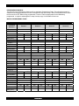
RS232 Command Strings
The following Table details the allowable RS232 Command Strings for control of the ISM4. Note only Source 1
can be controlled for ON/OFF. Automatic Source Power State Notification is an optional feature that will
automatically output a report any time there is a change of state on any Sense Input. The function can be
enabled/disabled using the Command Strings in the following Table. The actual report messages are detailed in
the ISM4 Queries Table (Return).
Name
Source 1 Discrete ON
Source 1 Discrete OFF
Source 1 Toggle Power
ISM4 RS232 COMMAND STRINGS
Command
Return
!1PR1+
OK{CR}
ERROR{CR}
!1PR0+
OK{CR}
ERROR{CR}
!1PT+
OK{CR}
ERROR{CR}
Remarks
Turn Source 1 ON
Turn Source 1 OFF
Toggle Source 1 Power
(If OFF turn ON; If ON
turn OFF)
Enable Automatic Source
1ZA1+
OK{CR}
Enable Automatic Source
Power State Notification
ERROR{CR}
Power State Notification
Disable Automatic Source
1ZA0+
OK{CR}
Disable Automatic Source
Power State Notification
ERROR{CR}
Power State Notification
NOTE: Allowable Syntax for the Command Strings includes: (Source 1 Discrete ON used for example)
!1PR1+
!01PR1+
!1PR01+
!01PR01+
ISM4 Queries
The ISM4 supports two layers of Source Power Notifications. The first is supported via explicit RS232 Queries
(via the Source Power Query described in the Queries Table). The second is launched automatically by the
25
ISM4 INSTALLATION & PROGRAMMING MANUAL
system upon detection of a change of state on any Source Sense Input. This feature can be enabled/disabled
via the Enable/Disable Automatic Source Power Notification Commands explained in the ISM4 RS232
Command Strings Table above.
The Source Power Notification Data String contains Power Status information for all four Sources. The
Notification Data Structure is preceded by the ‘#’ character prefix and terminated with the ‘+’ character. The
Notification Data String is parsed into four fields. Each field holds one Source Component State Data
Structure (one per Source Component). Each Source Component Data Structure holds information that
identifies the particular source component and its power state, as indicated by the definition of {0/1}, a ‘0’
indicates the OFF condition. A ‘1’ indicates an ON condition.
Example
#SS{S#} PR{0/1}
SS{S#} PR{0/1}
SS{S#} PR{0/1}
SS{S#} PR{0/1}+
The SS{S#} field indicates which Source is being reported. All data that follows will pertain to that Source. The
end of the current field will be flagged by the presence of another SS{S#} field (next Source) or the ‘+’ termination
character (end of report).
The PR{0/1} field indicates the Power State of the reported Source. That is, it indicates the Power State of the
Source identified by the SS{S#} field that immediately precedes it.
The string below is an example of a string that might be sent out by the ISM4:
#SS1 PR1 SS2 PR1 SS3 PR0 SS4 PR0+
This string indicates the following:
Source 1 Power State = ON
Source 2 Power State = ON
Source 3 Power State = OFF
Source 4 Power State = OFF
The System Info Query can be useful in determining the build of a particular ISM4. On occasion, Xantech
Technical Personnel may ask for this information should a problematic situation occur.
Name
Source Power
Query
?{s#}PR+
System Info
?SI+
ISM4 QUERIES
Return
?{s#}PR{0/1}+
Example Return
?1PR0+{CR}
?SI
?SI
{Device:
Device:
IPM4,
IPM4, Device
Device Cde:
Cde:
000F,
000F,
Hardware Cde:
Hardware Cde:
0000,
0000,
Reserved Cde:
Reserved Cde:
0000,
0000,
Firmware Ver:
Firmware Ver:
X.Y.Z}+
1.0.0
NOTE: Allowable Syntax for the Queries includes: (Source 1 Power used for example)
?1PR+
?01PR+
RS232 Command String/Query Legend
{CR} = Carriage Return
{s#} = Source Input Number Range 1-4 or 01-04
Remarks
Power in Zone 1 is
OFF
NOTE: This is
command does not
trickle down to the
Expansion Port.
X = Major
Y = Minor
Z = Release
ISM4 INSTALLATION & PROGRAMMING MANUAL
26
{0/1} = Either 0 (zero) or 1 (one); 0 = OFF, 1 =ON
CLONING THE ISM4
When necessary, the Macro Table (All Source ON and OFF Macros and their contents) can be cloned from a
programmed ISM4 to another ISM4. The cloning process requires a Xantech Null Stereo 3.5mm Mini Cable,
(Xantech Part No 06028145). DO NOT USE A STANDARD STEREO MINI CABLE FOR CLONING. To clone an
ISM4:
1. Using a Xantech Null Stereo 3.5mm Mini Cable, (Xantech Part No 06028145), connect the RS232 Port on
the programmed ISM4 to the RS232 Port on the unprogrammed ISM4.
2. In Normal Operating Mode, press the Prev Button on the Primary (programmed) ISM4 unit for longer than 2
seconds. The Source LED’s will flash fast for a few seconds and stop. Cloning is complete.
3. Install and use as programmed.
ISM4 INSTALLATION & PROGRAMMING MANUAL
27
OPERATING THE ISM4
Once setup, there is typically no direct interaction with the ISM4. It will automatically respond to system
conditions, IR and RS232 Commands.
System ON Mode
When the System Reference Device (Source 1) is turned ON, via a power button on the device, an IR remote
control, a RS232 Command etc, the ISM4 will detect the change of state (OFF to ON) and automatically enter
System ON Mode. In this mode, the first task that the ISM4 will take in response to the Off-to-On transition is to
execute the Power ON Macro associated with the Source 1 “Sense In” input. Recall that in executing this macro
(launched by a Source 1 “Sense In” trigger ONLY) the IR content of the first Command Structure will be
bypassed. Refer to the Sense In section for further information. Next, the ISM4 will ‘look’ at the Source 2-4
Sense Inputs, and if any one shows an OFF condition, the ISM4 will output the ON Macro associated with that
Source.
The Source LED’s will flash, by Source, when the ON Macros are being sent. The Front Panel Source 1-4
LED’s will illuminate solid green to indicate a sensed ON condition for each Source. If for some reason a
particular Source does not respond to an ON Macro, the ISM4 will resend that macro. The ISM4 will resend an
ON Macro up to four times. During the resends, the ISM4 Program LED will flash red indicating that an error has
occurred in executing an ON Macro and that the Source for which the macro is being resent is out of sync with
the system.
The ISM4 will continually scan the Sense Inputs. As long as Source 1 is ON (System ON Mode), if any of
Sources 2-4 turns OFF, for any reason, the ISM4 will automatically output the ON Macro for that Source,
keeping all Sources synced to the System ON Mode.
System OFF Mode
When the System Reference Device (Source 1) is turned OFF, via a power button on the device, an IR remote
control, a RS232 Command etc, the ISM4 will detect the change of state (ON to OFF) and automatically enter
System OFF Mode. In this mode, the first task that the ISM4 will take in response to the On-to-Off transition is to
execute the Power OFF Macro associated with the Source 1 “Sense In” input. Recall that in executing this macro
(launched by a Source 1 “Sense In” trigger ONLY) the IR content of the first Command Structure will be
bypassed. Refer to the Sense In section for further information. Next, the ISM4 will ‘look’ at the Source 2-4
Sense Inputs, and if any show an ON condition, the ISM4 will output the OFF Macro associated with that
Source.
The Source LED’s will flash, by Source, when the OFF Macros are being sent. The Front Panel Source 1-4
LED’s will turn off to indicate a sensed OFF condition for each Source. If for some reason a particular Source
does not respond to an OFF Macro, the ISM4 will resend that macro. The ISM4 will resend an OFF Macro up to
five times. During the resends, the ISM4 Program LED will flash red indicating that an error has occurred in
executing an OFF Macro and that the Source for which the macro is being resent is out of sync with the system.
The ISM4 will continually scan the Sense Inputs. As long as Source 1 is OFF (System OFF Mode), if any of
Sources 2-4 turns ON, for any reason, the ISM4 will automatically output the OFF Macro for that Source,
keeping all Sources synced to the System OFF Mode.
RC68 Triggered Commands
Externally, the ISM4 will behave in exactly the same manner as described in the Sections: System ON Mode and
System OFF Mode, when triggered by RC68 Trigger Commands. Internally if the ISM4 ‘sees’ the RC68 Source
1 ON Command it will look at the state of Source 1. If it is OFF the ISM4 will enter System ON Mode as
described. Conversely, if the ISM4 ‘sees’ the RC68 Source 1 OFF Command it will look at the state of Source 1.
If it is ON the ISM4 will enter System OFF Mode as described. If the ISM4 ‘sees’ the RC68 Toggle Power
Command, it will look at Source 1 determine the state (ON or OFF) and output the opposite state macro.
Please Note that unlike the case of a “Sense In” trigger on Source 1, the IR content of Command Structure
number 1 on either the ON and OFF macro will be executed.
ISM4 INSTALLATION & PROGRAMMING MANUAL
28
RS232 Triggered Commands
Externally, the ISM4 will behave in exactly the same manner as described in the Sections: System ON Mode and
System OFF Mode, when triggered by RS232 Trigger Commands. Internally if the ISM4 ‘sees’ the RS232
Source 1 ON Command it will look at the state of Source 1. If it is OFF the ISM4 will enter System ON Mode as
described. Conversely, if the ISM4 ‘sees’ the RS232 Source 1 OFF Command it will look at the state of Source
1. If it is ON the ISM4 will enter System OFF Mode as described. If the ISM4 ‘sees’ the RS232 Toggle Power
Command, it will look at Source 1 determine the state (ON or OFF) and output the opposite state macro.
Please Note that unlike the case of a “Sense In” trigger on Source 1, the IR content of Command Structure
number 1 on either the ON and OFF macro will be executed.
ISM4 INSTALLATION & PROGRAMMING MANUAL
29
APPENDIX
NAVIGATING AND EDITING MACROS
The six Front Panel Buttons each have multiple functions, depending upon the ISM4 Mode. The following
sections detail those functions within the different modes. An understanding of the button presses will help make
the programming process easier. For the actual programming instructions, see Section: Programming Macros.
Normal Operating Mode
In Normal Operating Mode the Front Panel Buttons are typically not used. They are used in this mode to clone a
new ISM4 and to enter Edit Mode.
Figure 9 Front Panel Navigation – Normal Operating Mode
PREV
In Normal Operating Mode, press for 2 seconds (Indicated by the first blink of the Active Source
LED) to initiate the Macro Table Clone Process. This will transfer the programming from one ISM4
to another. Macro Table Clone requires that both units are properly connected via their RS232
Ports. All Source LED’s will rapid flash green during the Macro Table Clone Process.
SEQUENCE In Normal Operating Mode, press for 2 seconds (Indicated by the first blink of the Active Source
LED) to put the ISM4 into Edit Mode. By default, the Source 1 and Program LED’s will illuminate
green to indicate Edit Mode.
In Normal Operating Mode the other Front Panel Buttons have no functions.
In Normal Operating Mode, a Source LED will illuminate solid green when the associated Sense Input ‘sees’ a
Sensor Control Voltage from a connected Sensor Module when the sensed source is ON and turn off when the
Sensor Control Voltage is cut when that same source is OFF.
ISM4 INSTALLATION & PROGRAMMING MANUAL
30
Edit Mode - Navigate Macros
Press the Front Panel Prev or Next Buttons and observe the LED’s to navigate Source ON and OFF Macros as
follows:
Figure 10 Front Panel Navigation – Edit Mode (Navigating Macros)
SEQUENCE In Normal Operating Mode, press for 2 seconds (Indicated by the first blink of the Active Source
LED) to enter Edit Mode. This will allow navigation of Source ON and OFF Macros. The Source 1
and Program LED’s will illuminate solid green, by default, to indicate Edit Mode, Source 1 ON
Macro selected. Source 1 LED green and Program LED orange indicates Source 1 OFF Macro
selected. Source 2 LED green and Program LED green indicates Source 2 ON Macro selected.
Source 2 LED green and Program LED orange indicates Source 2 OFF Macro selected, etc.
PREV
In Edit Mode a quick 1 second press will Navigate to the previous Command Structure. A press
of 2 seconds (Indicated by the first blink of the Active Source LED) will navigate to the previous
ON or OFF Macro. Wait for the Source LED of the newly selected Command Structure or Macro
to flash once before pressing any more buttons. To exit Edit Mode and enter into Normal Mode
press the PREV button for 5 seconds (Indicated by the second blink of the Active Source LED) or
cycle power off and on.
NEXT
In Edit Mode a quick 1 second press will navigate to the next Command Structure. A press of 2
seconds (Indicated by the first blink of the Active Source LED) will navigate to the next ON or OFF
Macro. Wait for the Source LED of the newly selected Macro to flash once before pressing any
more buttons.
TEST
In Edit Mode press to Test the selected Source ON or OFF Macro. Emitters must be connected
to the ISM4 and appropriate Sources to test Macros.
DELETE
In Edit Mode, a quick 1 second press will delete the current Command Structure. A 2 second
press (Indicated by the first blink of the Active Source LED), will delete the current Macro. A press
of 5 seconds (Indicated by the second blink of the Active Source LED) will delete the entire Macro
Table (all Macros).
ISM4 INSTALLATION & PROGRAMMING MANUAL
31
DELAY
In EDIT MODE a press of the DELAY button will cause the ISM4 to enter into DELAY Learn Mode.
This will allow the programmer to program a delay within a particular IR Command Structure,
even if there is no associated IR command in that Command Structure.
SEQUENCE In Edit Mode, with a Source ON or OFF Macro selected, press to initiate the IR Learn Mode.
PREV
In Edit Mode press for 5 seconds (Indicated by the second blink of the Active Source LED) at any
time to exit Edit Mode and return to Normal Operating Mode.
IR Learn Mode
Press the Front Panel Buttons and observe the LED’s to program Source ON and OFF Macros as follows:
Figure 11 Front Panel Navigation – IR Learn Mode
TEST
In IR Learn Mode press to Test a just learned and unsaved IR Command. The Source LED for
the Macro containing the learned command will flash green. The Program LED will blink once to
indicate that the IR waveform was generated without error. It will blink red otherwise. This does
not indicate that the IR waveform was successful in controlling the Source component. It is simply
an indication of the validity of the IR data. The Program LED will return to its previous state after
the command has been sent. Emitters must be connected to the ISM4 and appropriate Sources to
test IR Commands.
SEQUENCE In IR Learn Mode, press to save a learned and tested IR Command. This action will automatically
exit IR Learn Mode and enter Edit Mode. Recall that full navigation on a Command Structure and
Macro level is permissible in Edit Mode.
DELETE
In IR Learn Mode, press to delete a non-functioning, learned but unsaved IR Command. The
ISM4 will automatically go back into Learn Mode to re-learn the command just deleted. (Same
Macro and Command Structure location.) If deleting a Command Structure (saved IR and
Delay) the Program LED will flash green once and return to its previous state. Press Sequence to
re-learn the IR Command for the deleted Command Structure.
DELAY
Not used in IR Learn Mode.
PREV
In IR Learn a press of the PREV Button will cause the ISM4 to exit IR Learn Mode and enter
Edit Mode.
ISM4 INSTALLATION & PROGRAMMING MANUAL
NEXT
PREV
32
Not used in this IR Learn Mode.
If not save of any learned IR is desired, press to return to Edit Mode.
Delay Program Mode
Press the Front Panel Buttons and observe the LED’s to program Delays in Command Structures as follows:
NOTE: Upon entering Delay Edit Mode, the Delay Value is reset to 0 seconds.
Figure 12 Front Panel Navigation – Delay Program Mode
DELAY
NEXT
Not used in this Delay Program Mode.
In Delay Program Mode each press will increase the amount of delay by one second from 0-60
seconds. After 60 seconds a press of the Next Button will set the delay to 0 seconds.
PREV
In Delay Program Mode each press will decrease the amount of delay by one second from 0 to
60 and down to 0 second. After 0 seconds a press of the Prev Button will set the delay to 60
seconds.
TEST
After a delay duration has been selected, but not saved, a press of the Test Button will initiate the
delay. The currently selected Source LED will flash the number of times equal to the duration of
the delay.
DELETE
Press to remove delay value in the currently selected Command Structure.
SEQUENCE Press to save a delay to a Command Structure. This action will automatically exit IR Learn Mode
and enter Edit Mode. Recall that full navigation on a Command Structure and Macro level is
permissible in Edit Mode.
33
ISM4 INSTALLATION & PROGRAMMING MANUAL
SPECIFICATIONS
Dimensions
5.25 W x 2.875 D x 1.6525 H (133.35 x 73.025 x 42mm)
Weight
0.76 lbs (0.34 kg)
Power
2.1mm coaxial jack
12V DC @ 0.5A
IR Learning Bandwidth
30KHz-100KHz
Macros
ON Macros
OFF Macros
4
4
Sensor Jacks
4 – Stereo 3.5mm mini jacks
Emitter Jacks
4 – 3.5mm mini jacks
IR Receiver Jack
1 – Stereo 3.5mm mini jack
IR Control In Jack
1 – 3.5mm mini jack
RS232
RS232 Port
Baud Rate
Parity
Data Bits
Stop Bits
Flow Control
1 – Stereo 3.5mm mini jack
9600
None
8
1
None
ISM4 INSTALLATION & PROGRAMMING MANUAL
[ BLANK PAGE ]
34
ISM4 INSTALLATION & PROGRAMMING MANUAL
[ BLANK PAGE ]
35
ISM4 INSTALLATION & PROGRAMMING MANUAL
36
Xantech Corporation
13100 Telfair Avenue, 2/F
Sylmar, CA 91342
818.362.0353 Tech Support ext. 353
www.xantech.com
Installation and Programming Manual, ISM4 Intelligent System Manager
© 2008 Xantech Corporation, Document # 08905136B
This document is copyright protected. No part of this manual may be copied or reproduced in any form without
prior written consent from Xantech Corporation.
Xantech Corporation shall not be liable for operational, technical, or editorial errors/omissions made in this
document.