1
INSTALLATION INSTRUCTIONS
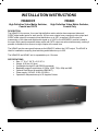
HD44CC5
HD44C
High Definition Video Matrix Switcher,
Coaxial and CAT5
High Definition Video Matrix Switcher,
Coaxial Only
DESCRIPTION
The HD44CC5 four-source, four-zone high-definition matrix switcher has component video and
S/PDIF digital audio inputs for each source. All four zone outputs have component video output and
S/PDIF audio output for economical local distribution up to 250’, as well as a RJ45 output for
transmission of the video and digital audio signal up to 1000’ to the HDRXSG01 receiver located in
the zone. Both coaxial component video output and CAT5 output are active simultaneously, making it
possible to distribute four sources to eight outputs at the same time.
The HD44C has the same great features as the HD44CC5 without the CAT5 output. The HD44C is
ideal for installations requiring local switching and distribution up to 250’.
The HD44CC5 and HD44C unit is expandable up to 16 zones.
SPECIFICATIONS
Size: 17” W x 7 3/8” D x 3 15/16” H
Weight: 9.25 lbs (4.2 kilos)
Controllable through IR and RS232 commands
Bandwidth supports resolutions of 1080p, 1080i, 720p, 480p and 480i.
Optional Rack Mount kit available (RM2UKIT)
Power supply (120VAC, 0.25A, 50-60Hz)
Operates in temperatures up to 55 degrees Celsius.
08905071B
-1-
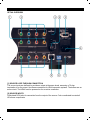
DETAIL OVERVIEW
[1] SOURCE LOOP-THROUGH CONNECTION
The source inputs are buffered to provide an output at the same levels, assuming a 75-ohm
termination is on the output. Use these connections for HD44 expansion systems. The buffers are an
active circuit. The HD44 must be powered on for an active connection.
[2] SOURCE INPUTS
Gold-plated RCA jacks for connection from the output of the source. Color coordinated to match all
HD source components.
08905071B
-2-
[3] IR RECEIVER
The rear panel IR receiver is a 3.5mm Stereo jack that is compatible with all Xantech IR receivers,
such as the 291-10. Switch 4 must be in the OFF position to use this jack.
PLUG
TIP
RING
SLEEVE
CIRCUIT
IR SIGNAL
GROUND
+12VDC, 25mA
[4] IR BUS, EMITTER PORT
The 3.5mm Mono jack is an emitter port. The IR signal is connected to the IR Receiver. A Xantech
283M emitter can be connected to this port.
PLUG
2-Pin WECO
TIP
+
SLEEVE
-
CIRCUIT
IR SIGNAL
GROUND
The 2-Pin WECO screw terminal is an IR port. The IR signal is connected to the IR Receiver. The
WECO screw terminal allows easy installation to a typical Xantech IR connecting block.
[5] RS232 (SERIAL) COMMANDS
The RS232 Port is bi-directional. The communication is set to 9600 Baud 8-N-1.
DB9 CONNECTOR
CIRCUIT
PIN
TX
2
RX
3
GND
5
08905071B
-3-
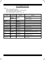
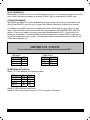
RS232 COMMAND STRUCTURE
Where:
{CR#} – Carriage Return (0x0D)
{z#} - Zone Number. Range is 1..4 (1..16 if expanded)
{s#} - Source Input Number. Range is 1..4
{0/1} – Either 0 (zero) or 1 (one). 0 – Off, 1 – On.
NAME
COMMAND
!{z#}PR01+
Zone Power
!{z#}PR00+
RETURN
OK{CR}
ERROR{CR}
REMARKS
To turn on Zone 2: !2PR1+ or !02PR1+ or
!2PR01+ or !02PR01+
To turn off Zone1: !1PR0+ or !01PR0+ or
!1PR00+ or !01PR00+
Zone Power
Toggle
!{z#}PT+
OK{CR}
ERROR{CR}
All Zones Off
!EO+
OK{CR}
ERROR{CR}
Turns all the zones off.
All Zones On
!EA+
OK{CR}
ERROR{CR}
Turns all the zones on.
Zone Restore All
!RF+
OK{CR}
ERROR{CR}
Restore all the Zone-to-Source routing to the
current selection: !RF+
Input (Source)
Select
!{z#}SS{s#}+
OK{CR}
ERROR{CR}
To set Zone 1 to Source Input 4: !1SS4+
Ping Expansion
Port
!RP+
OK{CR}
ERROR{CR}
Request that any unit connected to the expansion
port respond with a ping.
Return Ping to
Xantech port
!SP+
+
Returns a +. Meant for inter-expansion box
communications.
08905071B
-4-
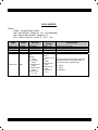
RS232 QUERIES
Where:
{CR#} – Carriage Return (0x0D)
{z#} - Zone Number. Range is 1..4 (1..16 if expanded)
{s#} - Source Input Number. Range is 1..4
{0/1} – Either 0 (zero) or 1 (one). 0 – Off, 1 – On.
NAME
EXAMPLE
RETURN
QUERY
RETURN
Zone Power
?{z#}PR+
?{z#}PR{0/1}+
?4PR0+{CR}
Power in zone 4 is OFF.
Input Select
?{z#}SS+
?{z#}SS{s#}+
?4SS3+{CR}
Zone 4 currently has source 3 selected.
?SI+
?SI
{Device:
HD44,
Device Cde:
000C,
Hardware Cde:
0000,
Reserved Cde:
0000,
Firmware Ver:
X.Y.Z}+
System Info
08905071B
?SI
Device:
HD44, Device
Cde:
000C,
Hardware Cde:
0000,
Reserved Cde:
0000,
Firmware Ver:
1.1.0
EXPLANATION
This command is used only with single unit
systems. Note this is command does not
trickle down to the expansion port.
X = Major
Y = Minor
Z = Release
-5-
[6] AC POWER INPUT
Standard IEC 3-Conductor AC Line Cord Receptacle for plug-in of a 3-conducator power line cord. Be
sure to note if the power receptacle is domestic (120VAC type) or international (240VAC type).
[7] RS232 EXPANSION
The HD44C and HD44CC5 can be expanded into a larger system. By using any combination of the
HD44C and HD44CC5 (up to 4 units), a larger High-Definition distribution system can be created.
For instance, two HD44C units can be combined to create a much larger 4 source input to 8 zone
output. The two HD44C units must have their own unique address (see ADDRESS (DIP SWITCH)
section). The top unit (master controller) must always be addressed as UNIT 1. See Section 8 for
setting the unit address. The included RS232 expansion cable allows a single RS232 control port to
be used to command the entire system. The expansion cable is connected between the DB9 (5) and
3.5mm stereo mini jack (7).
IMPORTANT NOTICE
The top unit (master controller) must always be addressed as UNIT 1.
DB9 MALE
CIRCUIT
TX
RX
GND
3.5MM PLUG
PLUG
CIRCUIT
TIP
TX
RING
RX
SLEEVE GND
PIN
2
3
5
[8] ADDRESS (DIP SWITCH)
Switch 1 & 2: Unit Address (for Expansion mode)
ADDR
UNIT 1
UNIT 2
UNIT 3
UNIT 4
SW 1
OFF
OFF
ON
ON
SW 2
OFF
ON
OFF
ON
Switch 3: ON for firmware write protect
Switch 4: ON for front panel IR receiver / OFF for rear panel IR receiver
08905071B
-6-
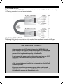
[9] CAT5 ZONE OUTPUT
Output connection to the HDRXSG01 receiver module. Uses standard CAT5 cable. Be sure to verify
CAT5 wiring connection is correct before installation.
[10] COAXIAL ZONE OUTPUT
Gold-plated RCA jacks for connection to an HD monitor. Color coordinated to match all HD type
products. The CAT5 and coaxial output can be used at the same time.
IMPORTANT NOTICE
After connecting the CAT5 cable to the receiver (HDRXSG01), the
power supply to the receiver should be unplugged for a few seconds
and then reconnected. This allows the receiver to go through the full
process of line length and line quality self-calibration.
Do not connect the power supply to the receiver until after the CAT5
connection. The HD44CC5 must be powered on before the
HDRXSG01.
As an alternate process to this procedure, the power may be cycled
off for a few seconds and reapplied to accomplish the same full selfcalibration process.
If for some reason the system losses power at the receiving end
(HDRXSG01), the transmitting end (HD44CC5), or both ends, the full
self-calibration process will automatically occur.
08905071B
-7-
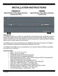
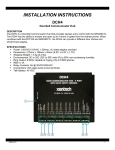
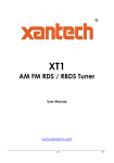
QUICK INSTALLATION: HD44CC5 and HDRXSG01
[1] Connect the High-Definition Source to the HD44CC5 or HDTXSG01. Figure 1 below shows a
HD44CC5 (video matrix transmitter) connected to the HDRXSG01 (receiver).
[2] Using CAT5 cable, connect the HD44CC5 zone output or the output from the HDTXSG01 to the
HDRXSG01. Connect power to the HD44CC5 first. Then connect power to the HDRXSG01.
[3] On the HD44CC5, set the source to zone to enable the HDRXSG01 from the connected HighDefinition source. See HD44CC5 manual on how to use RS232 and IR RC68+ controls.
[4] Installation Complete! No adjustments needed!
08905071B
-8-
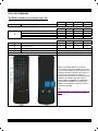
RC68+ (IR) COMMANDS
The RC68+ should be set to Group Code “C0”.
1
Zone Power Toggle
2
Zone 1 Source Select
Zone 2 Source Select
Zone 3 Source Select
Zone 4 Source Select
3
4
5
6
7
Zone Power On
Zone Power Off
Zone Power All Off
Zone Restore All
Zone Power All On
ZONE 1
80
ZONE 2
48
ZONE 3
10
ZONE 4
90
SRC 1
00
40
20
60
SRC 2
C0
A0
E0
88
SRC 3
50
30
70
18
SRC 4
D0
B0
F0
98
ZONE 1
08
28
ZONE 2
A8
E8
ZONE 3
38
78
ZONE 4
B8
F8
68
C8
58
Note: For expanded systems, the ‘Primary’
HD44 should remain on the default group code
of “C0” but each additional HD44 will need to be
changed to a different discrete Code Group so
the units can be individually controlled. To
change the Group Code of the additional HD44’s
please see the RC68X instruction manual
(section labeled CHANGING THE INTERNAL
CODE GROUP NUMBER OF A XANTECH
MODEL) or the Application Advisory AA-09 on
the Xantech Web Site
[URL:
http://www.xantech.com/products/a_folder/a_aa
09.pdf
08905071B
-9-
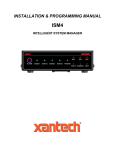
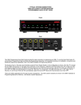
ADVANCE INSTALLATION
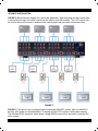
FIGURE 2: Below shows a diagram for a sports bar application. With the equipment rack located near
or behind the bar area, the coaxial outputs can be used for local HD monitors. The CAT5 outputs can
be used to deliver HD content to areas such as outdoor patios and pool table recreational areas.
FIGURE 2
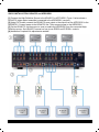
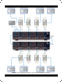
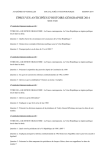
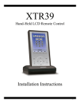
FIGURE 3: The figure in the next page shows an expanded HD44CC5 system. With two HD44CC5
devices, HD content can be distributed to 16 displays (8 with CAT5 outputs, 8 with coaxial outputs).
The included RS232 expansion cable allows a single RS232 control port to be used to command the
entire system.
08905071B
- 10 -
FIGURE 3 (Note: The top unit (master unit) must be addressed as UNIT #1)
08905071B
- 11 -
COMMON PROBLEMS AND TROUBLESHOOTING
Poor video quality (picture is washed out): Several manufacturers of cable and satellite box may
have higher than normal DC offset on the video signals. When connected to an HD44C, HD44CC5,
and HDTXSG01, this may result in a washed out picture. To remedy this problem, a DC blocker
should be used between the source component and the HD44C, HD44CC5, and HDTXSG01.
Picture appears to be blooming: A blooming picture is usually caused by a video signal that is too
high. One reason for this problem is the HDRXSG01 was not synchronized to the HD44CC5. To
correct this, be sure the CAT5 cables is connected between the HD44CC5 and HDRXSG01. Remove
power from both devices. Simultaneously apply power to both units. This will synchronize the correct
signal strength.
Xantech Corporation
13100 Telfair Avenue, 2/F
Sylmar, CA 91342
www.xantech.com
Phone: (818) 362-0353, Fax: (818) 362-9506
Installation Instructions, HD44CC5, HD44C © 2007 Xantech Corporation
This document is copyright protected. No part of this manual may be copied or reproduced in any form without prior
written consent from Xantech Corporation.
Xantech Corporation shall not be liable for operational, technical, or editorial errors/omissions made in this document.
Document Number 08905071B
08905071B
- 12 -
This page intentionally left blank
08905071B
- 13 -
This page intentionally left blank
08905071B
- 13 -
This page intentionally left blank
08905071B
- 13 -
Xantech Limited Warranty
(Effective for products sold after July 1, 2006)
Xantech Corporation (“Xantech”) warrants to the holder of a valid proof of purchase as the first end-user purchaser
(“You”), its products to be free from defects in materials and workmanship for the periods specified below from the date of
purchase. This limited warranty extends only to You for product purchased and used in the United States of America. For
product purchased outside of the United States of America, the terms of this warranty apply EXCEPT that You must
contact the Xantech authorized distributor in your region for warranty services. Product is not intended for end user
installation. If within the applicable warranty period above You discover such item was not as warranted above and You
promptly notify Xantech in writing, Xantech shall repair or replace the items at its option. Xantech may elect which remedy
or combination of remedies to provide in its sole discretion. Xantech may use functionally equivalent
reconditioned/refurbished/pre-owned or new products or parts under this limited warranty. This warranty shall not apply
(a) to product which shall have been installed by other than an authorized Xantech installer, (b) to installed product which
is not installed to Xantech’s specifications, (c) to product which shall have been repaired or altered by others than
Xantech, (d) to charges for installation or set up or adjustment of customer controls, (e) to product that has suffered
normal cosmetic deterioration (f) to product which shall have been subjected to negligence, misuse, abuse, accident, or
damage by circumstances beyond Xantech’s control, including, but not limited to, lightning, flood, electrical surge,
tornado, earthquake, or any other catastrophic events beyond Xantech’s control, or (g) to product which shall have been
subjected to improper operation, connected equipment failure or malfunction, inadequate packing or shipping damage,
maintenance or storage, or to other than normal use of service. The foregoing warranties do not cover reimbursement for
labor, transportation, shipping, removal, installation, or other expenses which may be incurred in connection with repair or
replacement. All claims for product shipping damage must be processes within 3 days of receipt by You.
A Xantech Return Authorization (RA) must be obtained from Xantech by You, your installer or your distributor for Product
covered under this warranty. Covered product must be sent to Xantech together with proof of purchase, RA number,
prepaid and insured to Xantech. Freight collect shipments will be refused. Risk of loss or damage in transit is borne by the
sender. Xantech's warranty does not cover Products which have been received improperly packaged, altered, or
physically damaged. Products will be inspected upon receipt.
Except as may be expressly provided and authorized in writing by Xantech, Xantech shall not be subject to any
other obligations or liabilities whatsoever with respect to equipment manufactured or sold by Xantech or services
rendered by Xantech.
THE FOREGOING WARRANTIES ARE EXCLUSIVE AND IN LIEU OF ALL OTHER EXPRESSED AND IMPLIED
WARRANTIES, INCLUDING BUT NOT LIMITED TO IMPLIED WARRANTIES OF MERCHANTABILITY AND
FITNESS FOR A PARTICULAR PURPOSE.
ATTENTION: TO OUR VALUED CONSUMERS
To insure that consumers obtain quality pre-sale and after-sale support and service, Xantech products are sold
exclusively through authorized dealers and authorized distributors. Xantech products are not sold online. The
warranties on Xantech products are NOT VALID if the products have been purchased from an unauthorized
distributor or an online E-tailer. In order to determine if your Xantech re-seller is authorized, please call Xantech
(800) 843 - 5465.
XANTECH PRODUCT (go to Xantech.com/warranty for model numbers)
IR Receivers and IR Emitters
WARRANTY DURATION
Limited Lifetime
A/V distribution and Control
Limited Lifetime
Remote Control Switchers
Limited Lifetime
Modules and Connecting Blocks
Limited Lifetime
Accessories
Limited Lifetime
Speakers
Limited Lifetime
Volume Controls and Speaker Selectors
MRC, BX, ZPR and Commercial Products
5 year Limited
2 year Limited
Amplifiers
2 year Limited
Control Interfaces
Hand Held Remote Controls
2 year Limited
1 year Limited
SPLCD Product
1 year Limited
Source Components
1 year Limited