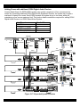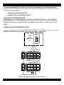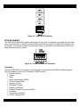
1
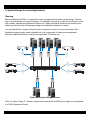
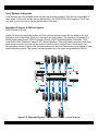
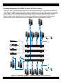
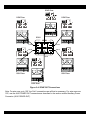
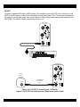
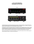
INSTALLATION INSTRUCTIONS
D5XH
DIGI-5 DDS Digital Distribution System
Rack Mount, 6 Zone Expansion Hub
08905154B
-1-
Safety Information
CAUTION: TO REDUCE THE RISK OF ELECTRIC SHOCK, DO NOT
REMOVE COVER (OR BACK). NO USER SERVICEABLE PARTS
INSIDE.
REFER SERVICING TO QUALIFIED SERVICE PERSONNEL.
The lightning flash with arrowhead symbol within an equilateral triangle
is intended to alert the user to the presence of uninsulated "dangerous
voltage" within the product's enclosure that may be of sufficient
magnitude to constitute a risk of electric shock to persons.
The exclamation point within an equilateral triangle is intended to alert
the user to the presence of important operating and maintenance
(servicing) instruction in the literature accompanying the appliance.
WARNING: TO REDUCE THE RISK OF FIRE OR SHOCK,
DO NOT EXPOSE THIS APPLIANCE TO RAIN OR MOISTURE.
IMPORTANT SAFETY INFORMATION
Read Information — All the safety and operating information should be read before the appliance is operated.
Follow Information — All operating and use information should be followed.
Retain Information — The safety and operating information should be retained for future reference.
Heed Warnings — All warnings on the appliance and in the operating instructions should be heeded.
Wall Mounting — Mounting of this appliance should be done only by an authorized installer.
Ventilation — The appliances should be situated so that their location or position does not interfere with their proper
ventilation. These appliances should never be placed near or over a radiator or heat register. These appliances should not
be placed in a built-in installation such as a bookcase or cabinet that may impede the flow of air through the ventilation
openings.
Non-Use Periods — Appliances that are left unattended and unused for long periods of time should be de-energized.
Grounding or Polarization — Do not defeat the safety purpose of the polarized or grounding-type plug. A polarized plug
has two blades with one blade wider than the other blade. A grounding type plug has two blades and a third grounding
prong. The polarized wide blade and the third prong are provided for your safety. If the provided plug does not fit your
outlet, consult an electrician for replacement of the obsolete outlet.
Power Cord Protection — Protect the power cord from being walked on or pinched particularly at plugs, convenience
receptacles and the point where they exit from the apparatus.
Water — Do not use the apparatus near water.
Cleaning — Unplug the apparatus from the power outlet before cleaning. Use only a dry cloth to clean the apparatus.
Power Lines — An outdoor antenna should be located away from power lines. When installing an outside antenna
system, extreme care should be taken to avoid touching power lines or circuits, as contact with them may be fatal.
Object and Liquid Entry — Never insert objects of any kind through the openings of these appliances, as they may
touch dangerous voltage points or short-out parts that could result in a fire or electric shock. Care should be taken so that
objects do not fall and liquids are not spilled into the appliance through openings in the enclosure.
Servicing — Do not attempt to service these appliances yourself, as opening or removing covers may expose you to
dangerous voltage or other hazards. Refer all servicing to qualified service personnel.
08905154B
-2-
Damage Requiring Service — These appliances should be serviced by qualified service personnel when:
• A power supply connection or a plug has been damaged or
• If liquid has been spilled into the appliance or objects have fallen into the appliance or
• The appliance has been exposed to water or moisture or
• The appliance does not appear to operate normally or exhibits a marked change in performance or
• The appliance has been dropped or the enclosure damaged.
Replacement Parts — When replacement parts are required, be sure the service technician has used replacement parts
specified by the manufacturer or that have the same characteristics as the original part. Unauthorized substitutions may
result in fire, electric shock, or other hazards.
Safety Check — Upon completion of any service or repairs to this audio product, ask the service technician to perform
safety checks to determine that the audio product is in proper operating condition.
Lightning Storms — Unplug this apparatus during lightning storms or when unused for long periods of time.
Attachments and Accessories — Use only attachments/accessories specified by the manufacturer.
Cart, Stand, Tripod, Bracket or Table — Use only with a cart, stand, tripod, bracket or table specified by the
manufacturer, or sold with the apparatus. When a cart is used, use caution when moving the cart/apparatus combination
to avoid injury from tip over.
Disconnect Device — Where the mains plug or an appliance coupler is used as the disconnect device, the disconnect
device shall remain operable.
NOTE: This equipment has been tested and found to comply with the limits for a Class B digital device, pursuant to part
15 of the FCC Rules. These limits are designed to provide reasonable protection against harmful interference in a
residential installation. This equipment generates, uses and can radiate radio frequency energy and, if not in-stalled and
used in accordance with the instructions, may cause harmful interference to radio communications. However, there is no
guarantee that interference will not occur in a particular installation.
If this equipment does cause harmful interference to radio or television reception, which can be determined by turning the
equipment off and on, the user is encouraged to try to correct the interference by one or more of the following measures:
• Reorient or relocate the receiving antenna.
• Increase the separation between the equipment and receiver.
• Connect the equipment into an outlet on a circuit different from that to which the receiver is connected.
• Consult the dealer or an experienced radio/TV technician for help.
CAUTION: Changes or modifications not expressly approved by Xantech could void the user’s authority to operate the
equipment
Caring For the D5XH
Clean only with a dry soft cloth.
It is important to properly care for your D5XH DDS Hub. Follow these guidelines to ensure your device is preserved and
protected.
• Do not expose the D5XH to rain, liquids or moisture for an extended period of time.
• Do not expose the D5XH to temperature extremes.
• Do not place any objects on top of the D5XH to prevent chassis damage.
Operating Temperatures & Environments
Operating Temperature: 32-104°F (0-40° C)
Humidity: 0-90%
Precautions
• Always exercise care when operating the D5XH Digital Audio Distribution Hub.
• Do not install near any heat sources such as radiators, heat registers, stoves, or other apparatus (including
amplifiers) that produce heat.
• In the unlikely event that smoke, abnormal noise, or strange odor is present, immediately power the D5XH off.
Please report the problem to your dealer immediately.
• Never attempt to disassemble the D5XH. You will lose any product warranty on the unit.
08905154B
-3-
1. Introduction
Modern Convenience
The D5XH 4 Source, 6 Zone Digital Audio Expansion Router, when used with the D5RH Digital
Audio Router, provides the ability to listen to 4 different audio sources in up to 28 separate areas of
the home for total flexibility and convenience. No need to have multiple audio systems in different
areas, just select a source from one of Xantech’s premium in-wall keypad, sit back and enjoy!
Crystal Clear Digital Sound
End-to-end digital architecture means that the entire signal path of the audio system remains in the
digital domain from start to finish. This means that noise, signal loss and other unwanted effects are
never present. Each keypad contains a 30 Watt digital amplifier that allows the user to play music at
loud volume when desired. This also means that music at any volume is full and rich, without
distortion and with plenty of bass!
Simple, Logical Installation
The D5RH and D5XH connect with CAT-5 and speaker wire, making them reliable and easy to install.
Any digital or analog audio source can be connected directly to the D5XH Digital Audio Router, or
remotely using a D5IP Local Source Wall Plate. Keypads and Wall Plates are connected to the D5XH
using CAT-5 wiring (inexpensive and reliable), while speakers are connected to D5KP Amplified
Keypads using traditional speaker wire.
Entertaining Possibilities
The D5XH’s Whole House Music and Zone Grouping features make entertaining more fun than ever.
Fully customized audio options allow for control of the entire house from one location and also allow
for the creation of multiple-zone linking where groups of zones work together.
Control for Parents
The Source Lock Out feature allows you to disable specific sources in the kid’s rooms that you don’t
want them to access.
About DIGI-5 Technology
DIGI-5 is a revolutionary new technology standard that provides a complete end-to-end digital audio
solution over CAT-5 wiring. DIGI-5 is based on advanced digital distribution and amplification circuits
that allow multi-room audio systems to be installed quickly and cost effectively.
DIGI-5 is a collaboratively developed technology that is licensed by the Linear Home Technology
Group and is being initially integrated on a Linear group-wide basis, targeted to expand market and
consumer acceptance of such systems.
08905154B
-4-
Features
•
•
•
•
•
•
•
•
•
•
•
•
•
•
•
4 Source, 6 Zone Expansion for D5RH Digital Audio Router
Combine Up to 4 D5XH Chassis for Total of Up to 28 Zones
Stand-Alone 4 Source 6 Zone Capability Expandable to 24 Zones
End-to-End Digital Architecture For Crystal Clear Sound with No Signal Loss
Simple Cat-5 Wiring requirements
Innovative D5KP Amplified Keypad Controllers (not included) Provide Custom Control Options
No PC Software Required for Setup-Simply Plug in D5KP Keypads and Go
D5RM Slim-line IR Remote Included
Whole House Music-Turns On All Zones to the Same Source
Zone Functions, Do Not Disturb, Source Lock Out, Tone Control, Balance, Loudness, Dynamic
Range Compression (DRC)
Local (In-Room) Source Connectivity with Optional D5IP Local Source Wall Plates
Supports all Features of D5RH Digital Audio Router
Paging/DB Functionality w/ Optional Communications Controller
Compact Single Rack Space Design
Rack Mountable – Optional Rack Ear Kit Available (RM1UKIT)
D5XH Accessories
•
•
•
•
•
•
D5RH 4 Source, 4 Zone Digital Audio Hub
D5KP Amplified Keypad Controller
D5IP Source Input Wall Plate
D5MR Slim-line IR Remote
D5LR Learning Remote Control
RM1UKIT 1U Rack Ear Kit
08905154B
-5-
Defining Terms
Zone
A Zone is defined as an area of the house that has separate source selection capabilities from all
other areas of the house. Typically, a zone is comprised of a single room, but it is possible for a zone
to spread across multiple rooms (kitchen/dining room, master bedroom/master bath) or for multiple
zones to be contained in one room (game room/bar area or multiple zones in the yard).
Source
A Source is any audio (or audio/video) device that is connected to the SOURCE INPUTS of the
D5RH. Any Source can be heard in any zone in the system.
Local Source
A Local Source is an audio (or audio/video) device that is connected to a D5IP Source Input Wall
Plate. Local Sources are able to be heard only in the zone in which they are installed and may not be
heard in other zones of the system.
Front Panel
The front panel of the D5XH is populated simply by a Power LED and a power button. Figure
1-2 and Table 1-1 provide descriptions and locations of Front Panel controls and indicators.
4X4 DDS EXPANSION HUB
Figure 1.1: D5XH Front Panel
Indicator/Button Function
LED
1 Power LED
Indicates Power ON/OFF Status Red
2 Power Button
Turns System Power ON/OFF
Table 1.1: Front Panel
08905154B
-6-
Rear Panel
The Rear Panel of the D5XH has connections for Power, Source Loop Inputs (from D5RH), Source
Loop Outputs (to additional D5XH chassis), Zone Outputs, IR Outputs, Auxiliary Power, USB and
Expansion capabilities as well as Zone Pairing and Unit I.D. DIP Switches.
Figure 1-3 and Table 1-2 provide descriptions and locations of Rear Panel connections.
11
9
10
1
2
7
8
3
4
5
6
Figure 1-3: Rear Panel
1
Connector
Source Loop Input
2
Source Loop Output
3
4
5
Unit I.D. DIP Switches
Aux. Power Out Zones 1-3
Aux. Power Out Zones 4-6
6
AC Power Connector
7
Zone Output Ports
8
9
USB Port
Zone Pairing Switches
10 Expansion Port IN/OUT
11 RS232 Port
Function
Source Audio Inputs from D5RH
Source Audio Outputs to D5XH
Expansion Chassis
Sets Chassis Unit Identification
Provides Additional Power to Keypads
Provides Additional Power to Keypads
Plugs into 110 VAC Wall Outlet (Export
240VAC models also available)
Connect to D5KP Amplified Keypads Located
in Each Zone
For Firmware Updates
Links Multiple Zones Together
Control/Status Link Between D5RH
and Additional D5XH Chassis
RS232 Communication Port
Table 1.2: Rear Panel
08905154B
-7-
2. System Design Overview/Applications
Planning
Before installing the D5XH, it is essential to have a detailed and accurate system design. The first
step to a good design is to map the system. It is advisable to mark up a copy of the house floor plan
with speaker, keypad and equipment locations, etc. Make sure that all locations are decided upon
before pre-wiring so that all necessary wiring and installation hardware is in place.
It is essential that ALL system components are accounted for prior to the pre-wire stage. After
establishing design goals, make a detailed list of all components. Include source equipment,
Keypads, expansion Routers, local source wall plates, IR emitters, etc.
4X4 DDS EXPANSION HUB
D5XH
Figure 2-1: System Wiring Overview
Note: For clarity, Figure 2-1 shows a single zone connected to a D5RH and a single zone connected
to a D5XH Expansion Router.
08905154B
-8-
Pre-Construction
In a pre-construction installation, walls and ceilings are open with no drywall installed. This is
desirable and allows the installer greater access than in retro-fit applications.
Before actually running any wire or cable, take the time to look around each room or area of the
house and plan your wire paths for maximum efficiency. Look for routes through uncluttered parts of
the stud wall or ceiling that allow you to group all low-voltage (video, speaker wires, Cat-5, telephone,
etc.) wires wherever possible. It is a good practice to label both ends of all cables and to protect wires
by tying a plastic bag over the ends.
Note: Do not run low-voltage wires closer than 12" from high-voltage wires. If necessary, cross lowvoltage wires at a 90º angle to prevent interference.
Retro-Fit Wiring / Post Construction
Retro-fit installations are more difficult to complete than pre-construction because walls and ceilings
are intact. Typically wires must be fished into position through walls, floors and ceilings.
Holes must be cut; speakers mounted directly in the ceiling or walls with no rough-in brackets and
Keypads and local source wall plates must be mounted in existing drywall.
Pre-Wiring
D5XH to D5KP Keypads
The D5XH and all associated components are wired using Cat-5 terminated to the T-568A Wiring
Standard (Figure 2-2). When pre-wiring, run lengths of Cat-5 from the pre-determined equipment
location (the “head-end”) to each Keypad location. The Cat-5 routes all audio, power, IR and status
information needed for full system operation.
Note: For maximum performance over long runs (more than 150 ft) run an additional 16AWG 2conductor wire for external power.
1 2 3 4 5 6 7 8
BROWN/WHITE
BROWN
BLUE/WHITE
ORANGE
ORANGE/WHITE
BLUE
Shown tab
down
GREEN/WHITE
GREEN
1 2 3 4 5 6 78
Figure 2-2: T-568A Wiring Standard
Keypads to Speakers
Run 16AWG 2-conductor stranded copper speaker wire between keypad locations and speaker
locations.
08905154B
-9-
Local Sources to Keypads
Local sources are only available within the area that they are installed. They will not be available to
other areas of the house as they are not distributed by the D5RH/D5XH. Run lengths of Cat-5 from
any local (in-room) source to the keypad located in that area.
Expanded 4 Source, 8-28 Zone System
D5XH Expansion Router
Figure 2-5 shows an expanded system with four sources and ten zones with the addition of Local
Sources in four of the zones. Each zone can have one local source. The system is comprised of a
D5RH Digital Audio Router, D5XH Expansion Router, D5KP Amplified Keypad Controllers, D5IP
Local Source Wall Plates and Xantech XTC Series Speakers. This configuration provides audio from
each source into each zone as well as control of each source from each zone. Zones with Local
Sources have access to and control of those sources, but the Local Sources are not available to other
zones within the system. This system can be expanded up to 28 zones using additional D5XH’s.
D5RH
4X4 DDS EXPANSION HUB
D5XH
Figure 2-5: Expanded System - 4 Sources/10 Zones + Local Sources
08905154B
- 10 -
Stand-Alone (No D5RH) 4 Source, 6 Zone System
Figure 2-6 shows a stand-alone system with four sources and six zones with the addition of Local
Sources in two of the zones. Each zone can have one local source. The system is comprised of a
D5XH, D5KP Amplified Keypad Controllers, D5IP Source Input Wall Plates and Xantech XTC Series
Speakers. This configuration provides audio from each source into each zone as well as control of
each source from each zone. Zones with Local Sources have access to and control of those sources,
but the Local Sources are not available to other zones within the system. This system can be
expanded up to 24 zones using additional D5XHs (4 units in all).
4X4 DDS EXPANSION HUB
D5XH
Figure2-6: Stand-Alone 4 Source, 6 Zone
08905154B
- 11 -
Expanded Standalone (No D5RH) 4 Source, 6-24 Zone System
Figure 2-7 shows a stand-alone system with four sources and twenty four zones with the addition of
Local Sources in eight of the zones. Each zone can have one local source. The system is comprised
of four D5XH , D5KP Amplified Keypad Controllers, D5IP Source Input Wall Plates and Xantech XTC
Series Speakers. This configuration provides audio from each source into each zone as well as
control of each source from each zone. Zones with Local Sources have access to and control of
those sources, but the Local Sources are not available to other zones within the system.
4X4 DDS EXPANSION HUB
D5XH Unit# 1
4X4 DDS EXPANSION HUB
D5XH Unit# 2
4X4 DDS EXPANSION HUB
D5XH Unit# 3
4X4 DDS EXPANSION HUB
D5XH Unit# 4
Figure 2-7: Expanded System - 4 Sources/24 Zones + Local Sources
08905154B
- 12 -
3. Connections
The D5XH is part of an integrated system that requires the use of other components. Depending on
the system design, these components may include:
•
•
•
•
•
D5KP Amplified Keypad - at least one per zone required
D5IP Source Input Wall Plates - one per zone where a Local Source is desired
D5RH Hub – Main 4x4 Digital Distribution System Hub
Xantech Outdoor, Ceiling and In-Wall Speakers
Xantech IR Emitters and accessories
This section describes the connectivity between these various components and the source audio
components that comprise the system. Each D5RH/D5XH system is unique, and not all connections
will be made in every installation.
Important Safety Note: Make sure that the D5XH is powered OFF before making any connections.
Source Loop Inputs (SOURCE LOOP IN)
The Source Loop Inputs are used primarily when adding D5XH Routers to a D5RH in order to create
more than four zones. These connectors carry Audio, and IR information between the units and allow
seamless functionality in all areas of the home with no complicated cross-wiring, splicing or
specialized adapters needed. When adding a D5XH Router to a D5RH system, simply connect Cat-5
Patch Cables (included with the D5XH) from the SOURCE LOOP OUTs of the D5RH to the SOURCE
LOOP INs of the D5XH as shown in Figure 3-1. Complete connections for expanded systems are
described in the section entitled Multi-Chassis Connections.
D5RH
Cat-5 Ethernet
Patch Cables
D5XH
Figure 3-1: Source Loop Inputs
08905154B
- 13 -
EXPANSION IN
Connect the Cat-5 Patch Cable included with the D5XH from the D5RH’s EXPANSION OUT port to
the D5XH’s EXPANSION IN port as shown. Complete connections for expanded systems are
described in the section entitled Multi-Chassis Connections.
D5RH
D5XH
Cat-5
Ethernet
Patch Cable
Figure 3-2: Expansion In
ZONE OUT
The ZONE OUT RJ-45 connectors interface with D5KP Amplified Keypad Controllers through
Cat-5 cables wired to the T-568A Standard. These connectors carry IR information from the Keypads
as well as audio information to the Keypads. Status information is also carried between the
D5RH/D5XH chassis and the Keypads. While a great deal of information is handled by the ZONE
OUT connections, the connections are straightforward. Simply connect Cat-5 cables terminated to the
T-568A configuration (Figure 3-3) from each Keypad to the corresponding ZONE OUT connector as
shown in Figure 3-4.
1 2 3 4 5 6 7 8
BROWN/WHITE
BROWN
BLUE/WHITE
ORANGE
ORANGE/WHITE
BLUE
Shown tab
down
GREEN/WHITE
GREEN
1 2 3 4 5 6 78
Figure 3-3: T-568A Wiring Standard
08905154B
- 14 -
D5KP Rear
D5KP Rear
D5KP Rear
D5XH
Cat-5
Cat-5
Cat-5
Cat-5
Cat-5
D5KP Rear
D5KP Rear
D5KP Rear
Figure 3-4: ZONE OUT Connections
Note: For wire runs up to 150', the Cat-5 connections are all that is necessary. For wire runs over
150', use the AUX POWER OUT connectors as described in the section entitled Auxiliary Power
Connector (AUX POWER OUT).
08905154B
- 15 -
D5KP Speaker Connections
The D5XH sends a digital audio signal to connected D5KP Keypads where it is amplified and sent to
speakers.
WARNING!: The D5KP’s amplifier is capable of powering a single pair of 8-6 Ohm speakers.
DO NOT connect speakers with a rating of less than 6 Ohms! DO NOT connect more than one
speaker to either speaker connector of the D5KP. In doing this, damage to the D5KP may
occur and will void the products warranty.
To connect speakers to D5KP Keypads:
1. Ensure that system power is OFF!
2. Remove the SPEAKER CONNECTOR from the D5KP
3. Strip speaker wire back 1/4"
4. Loosen speaker terminal screws on the speaker connectors
5. Insert speaker wires into terminals making sure to maintain +/- polarity
6. Tighten screws on speaker terminals
7. Re-connect the terminal strip to the SPEAKER CONNECTOR on the D5KP
8. Connect speaker wires to the room speakers maintaining correct polarity
Figure 3-5: Speaker Connections
08905154B
- 16 -
Auxiliary Power Connector (AUX POWER OUT)
For wire runs over 150’, it is recommended to run an additional 16 AWG/2 conductor wire from the
head-end location to the Keypads locations. This will allow the AUX POWER OUT terminals to supply
additional power to the Keypads to compensate for the additional distance. For wire runs over 300’,
16 AWG/2 conductor wire is required. The maximum wire run using Cat-5 and 16 AWG/2 conductor is
600’. Make all connections between the D5XH and the D5KP Amplified Keypads as previously
described, then make the aux power connections described below.
To make connections:
1. Ensure that system power is OFF!
2. Strip the ends of the 16 AWG wire 1/4" on both ends of the wire run.
3. Remove the terminal strip from the AUX POWER OUT connector on the D5XH.
4. Loosen the screws for the appropriate zone’s terminal pairs on the terminal strip.
5. Insert the wires into the terminal strip, paying close attention to polarity (+/-).
6. Tighten the screws on the terminal strip.
7. Remove the terminal strip from the PWR IN connector of the D5KP.
8. Loosen the screws on the D5KP’s PWR IN terminal.
9. Insert the wires into the terminal, paying close attention to polarity (+/-).
10. Tighten the screws on the D5KP’s PWR IN terminal.
11. Connect the terminal strip back onto the AUX POWER OUT connector on the D5XH
Figure 3-6: AUX POWER OUT ZONES 1-3, 4-6, Connections
08905154B
- 17 -
USB Port (USB IN)
The USB IN port is designed to allow upgrades to the D5XH’s firmware.
AC Power Connector
Connect the supplied cord from the AC Power Connector into a properly grounded electrical outlet.
System Expansion
The D5XH is capable of supporting up to four sources to up to six zones. The system may be
expanded in two ways:
• Local Sources
•
Adding Zones (Additional D5XH chassis)
Local Sources
Each zone of a D5RH/D5XH-based system can have its own “Local” source connected directly to the
zone’s D5KP Amplified Keypads using a D5IP Source Input Wall Plate. A source connected to a
D5KP is accessible from the zone in which it is connected. It is NOT AVAILABLE to the other zones
of the system. Both audio and IR control capabilities are available to Local Sources through the
D5KP. A zone may have a maximum of one Local Source.
D5IP Source Input Wall Plate
A D5IP Source Input Wall Plate is required to add a Local Source to a zone. The wall plate has audio
and IR connections similar to the SOURCE INPUT of the D5RH. A run of Cat-5 terminated to T-568A
standard (see Figure 3-3, page 12) is required between the D5KP Amplified Keypads and the location
designated for the D5IP. Connections between a source component and the D5IP are detailed in
Figure 3-7, Figure 3-8 and Figure 3-9, while connections between the D5IP and the D5KP Amplified
Keypads are detailed in Figure 3-10.
Figure 3-7: Local Source to D5IP Connections – Analog
NOTE: Be sure the RCA/OPT/COAX switch is ‘up’ and set to ‘RCA’.
08905154B
- 18 -
Figure 3-8: Local Source to D5IP Connections - Digital Optical
NOTE: Be sure the RCA/OPT/COAX switch is ‘middle’ and set to ‘OPT’.
NOTE: Multi-channel digital audio formats (5.1, 7.1 etc.) are not supported by the D5IP, D5RH, or D5XH. However, many
audio/video sources allow you to change the digital output to PCM Stereo. In most cases this will allow multi-channel
audio sources to output a “summed” stereo signal through the digital output. Consult the audio/video source manual for
details.
NOTE: Some audio sources which utilize a digital output require that you enable the digital output before it will function. If
there is no audio present, check the setup menu of the audio source to confirm that the digital output is enabled.
Figure 3-9: Local Source to D5IP Connections - Digital Coaxial
NOTE: Be sure the RCA/OPT/COAX switch is ‘down’ and set to ‘COAX’.
08905154B
- 19 -
D5IP
Side View
D5KP Rear
Cat-5
L+
R+ RLSPEAKERS
-PWR IN+
Figure 3.10: D5IP to D5KP Connections
08905154B
- 20 -
IR OUT
Connect a standard IR Emitter (283D emitter, for example) from the IR OUT port on the front of the
D5IP to the IR receiver on the front of the audio source (see Figure 3.14). For sources that have an
IR Input port on the back of the unit, use a 3.5mm to 3.5mm mono interconnect cable (Xantech P/N:
06017400 1-Foot Mono Cable) instead (see Figure 3-12).
D5IP Front
CD
D5IP Front
Audio
Source
IR input
IR IN
3.5mm Mono
Interconnect
Cable
Figure 3-11: IR OUT to Local Source - IR Emitter
Figure 3-12: IR OUT to Audio Source 3.5mm Interconnect Cable
08905154B
- 21 -
Adding Zones to a D5RH Digital Audio Router
A basic D5RH system can contain a maximum of four sources and four zones. By adding D5XH
Digital Audio Routers, the system can contain a maximum of twenty-eight zones. Each D5XH
expands the system by up to six zones, while still maintaining a four source maximum limit. This
section details connections required for adding D5XH Digital Audio Routers to a D5RH.
# of Chassis
(1) D5RH
(1) D5RH, (1) D5XH
(1) D5RH, (2) D5XH
(1) D5RH, (3) D5XH
(1) D5RH, (4) D5XH
Max # of Zones
4
10
16
22
28
Zone X 4
Local Source
1 Per Zone
Sources X 4
Audio
Calbes
Cat 5
Zone X 6
Local Source
1 Per Zone
Cat 5
Audio
Calbes
IR Emitters
Cat 5
Zone X 6
D5RH
Local Source
1 Per Zone
Cat 5
Cat 5
Cat 5
D5XH
Cat 5
Cat 5
Zone X 6
Local Source
1 Per Zone
D5XH
Cat 5
Cat 5
Cat 5
Zone X 6
Local Source
1 Per Zone
D5XH
Cat 5
Cat 5
Cat 5
D5XH
Figure 3-13: Expanded System Overview
08905154B
- 22 -
Connections between a D5RH chassis and D5XH Digital Audio Routers involve Cat-5 patch cables
routed between the units. All cables are included with the D5XH. Connections are required for:
•
•
EXPANSION OUT/EXPANSION IN
SOURCE LOOP OUT/SOURCE LOOP IN
EXPANSION OUT/EXPANSION IN
Simply connect a Cat-5 patch cable from the D5RH’s EXPANSION OUT port to the first D5XH’s
EXPANSION IN port. For multiple D5XH units, connect a Cat-5 patch cable from the first D5XH’s
EXPANSION OUT port to the next D5XH’s EXPANSION IN port, and so on. See Figure 3-14 for
details.
SOURCE LOOP OUT/SOURCE LOOP IN
Connect a Cat-5 patch cable from each SOURCE LOOP OUT of the D5RH to each corresponding
SOURCE LOOP IN on the first D5XH. For multiple D5XH units, connect a Cat-5 patch cable from
each SOURCE LOOP OUT of the first D5XH to each corresponding SOURCE LOOP IN on the next
D5XH and so on. See Figure 3-14 for details.
D5RH
Cat-5
D5XH
Cat-5
D5XH
To Additional D5XH Chassis
Figure 3-14: System Expansion Connections
08905154B
- 23 -
D5XH ZONE OUT
Additional zones beyond the four that connect to the D5RH are connected directly to their
corresponding D5XH’s ZONE OUT ports using Cat-5. See Figure 3-15 for details.
D5KP Rear
Cat-5
L+
R+ RLSPEAKERS
-PWR IN+
D5XH
Figure 3-15: D5XH ZONE OUT Connections
Stand-Alone (No D5RH) 4 Source, 6 Zone System
Figure 3-16 shows a D5XH stand-alone system with four sources and six zones with the addition of a
local source in Zone 6. Each zone can have one local source. The system is comprised of a D5XH,
D5KP Amplified Keypads Controllers, D5IP Source Input Wall Plates and Xantech XTC Series
Speakers. This configuration provides audio from each source into each zone as well as control of
each source from each zone. Zones with Local Sources have access to and control of those sources,
but the Local Sources are not available to other zones within the system. This system can be
expanded up to 24 zones using additional D5XHs.
Sources
Zones x 6
Local Source
1 Per Zone
IR
Emitter
IR
Audio
Cables Emitter
IR
Audio
Cables Emitter
Audio
IR
Cables Emitter
Audio
Cables
Audio
Cables
Cat-5
D5IPs
Cat-5
Cat-5
D5XH
Figure 3-16: D5XH Stand-Alone Connections
08905154B
- 24 -
Adding Zones with additional D5XH Digital Audio Routers
A basic Stand Alone (No D5RH) D5XH system can contain a maximum of four sources and six
zones. By connecting additional D5XH Digital Audio Expansion Routers, the system can contain a
maximum of twenty four zones. Each D5XH expands the system by up to six zones, while still
maintaining a four source maximum limit. This section details connections required for adding D5XH
Digital Audio Routers to a D5XH Stand-Alone System.
# of Chassis
(1) D5XH
(1) D5XH, (1) D5XH
(1) D5XH, (2) D5XH
(1) D5XH, (3) D5XH
Max # of Zones
6
12
18
24
Sources
IR
Emitter
IR
Audio
Cables Emitter
Zones x 6
IR
Audio
Cables Emitter
Audio
IR
Cables Emitter
Local Source
1 Per Zone
Audio
Cables
Audio
Cables
Cat-5
D5IPs
Cat-5
Zones x 6
Cat-5
Local Source
1 Per Zone
Audio
Cables
Cat-5
Cat-5
Cat-5
Zones x 6
Local Source
1 Per Zone
Audio
Cables
Cat-5
Cat-5
Cat-5
Zones x 6
Local Source
1 Per Zone
Audio
Cables
Cat-5
Cat-5
Cat-5
Figure 3-17: Expanded System Overview
08905154B
- 25 -
Connections between a D5XH chassis in a Stand-Alone configuration and D5XH Digital Audio
Routers involve Cat-5 patch cables routed between the units. All cables are included with the D5XH.
Connections are required for:
•
•
EXPANSION OUT/EXPANSION IN
SOURCE LOOP OUT/SOURCE LOOP IN
EXPANSION OUT/EXPANSION IN
Simply connect a Cat-5 patch cable from the D5XH’s EXPANSION OUT port to the first D5XH’s
EXPANSION IN port. For multiple D5XH units, connect a Cat-5 patch cable from the first D5XH’s
EXPANSION OUT port to the next D5XH’s EXPANSION IN port, and so on. See Figure 3-18 for
details.
SOURCE LOOP OUT/SOURCE LOOP IN
Connect a Cat-5 patch cable from each SOURCE LOOP OUT of the D5XH to each corresponding
SOURCE LOOP IN on the next D5XH and so on. See Figure 3-18 for details.
D5IP
Source
Wall Plate
X4
Cat-5
D5XH
Cat-5
D5XH
To Additional D5XH Chassis
Figure 3-18: System Expansion Connections
08905154B
- 26 -
D5XH ZONE OUT
Additional zones beyond the six that connect to the D5XH are connected directly to their
corresponding D5XH’s ZONE OUT ports using Cat-5. See Figure 3-19 for details.
Figure 3-19: D5XH ZONE OUT Connections
4. Settings & Operation
DIP Switch Settings
There are two groups of DIP switches on the rear panel of the D5XH that must be set prior to
operation:
•
•
UNIT ID
KEYPAD PAIRING
UNIT ID
Each D5XH chassis has a corresponding DIP switch setting relative to the other chassis.
To set UNIT ID DIP switches:
1. Correctly identify which chassis controls the associated zones.
2. Assign a unique unit ID based on the silkscreen on the rear panel.
3. Repeat this process for the each other expansion chassis.
08905154B
- 27 -
Figure 4-1: UNIT ID DIP Switches
KEYPAD PAIRING
The KEYPAD PAIRING DIP switches allow each of the zones to be paired or grouped with any other
zone. Any zone that is in the UP position will be paired with any other zone that is also placed in the
UP position. This feature is useful to create large “party” zones where combined areas of the house
share audio and system control.
Figure 4-2: ZONE PAIRING DIP Switches
Operation
Once the D5RH/D5XH is connected, all functionality is controlled by the D5KP Amplified Keypads
that are installed in each zone. Essentially a D5KP controls:
• Source Selection
• Volume
• Mute
• Whole House Music (WHM)
• Do Not Disturb (DND)
• Source Lock Out
• EQ (Bass & Treble)
• Balance (Left/Right)
• Dynamic Range Compression (DRC)
• Loudness
• Power (Zone ON/OFF)
• All OFF (System OFF)
08905154B
- 28 -
Source control functionality is performed by IR Remote Control through the D5KP’s built-in IR
Receiver or an additional IR receiver connected to the Local IR Receiver Input on the back of the
D5KP. Complete instructions for installing and operating the Keypads are available in the
D5KP Amplified Keypads Controller Installation Manual.
Figure 4-3: D5KP Amplified Keypads
Appendix A: Specifications
Power Input
Sampling Frequency
Digital Audio Resolution
Signal to Noise Ratio
Frequency Response
Dimensions
H x W x D (w/ feet)
120 VAC / 3 Amps
(Export 240VAC models also
available)
48kHz
24 Bit
94dB
20Hz-20kHz +/- 0.1dB
2 3/8" x 17" x 14 1/8"
(8.6cm x 43.2cm x 35.9cm)
H x W x D (w/o feet)
1 3/4" x 17" x 14 1/8"
(4.4cm x 43.2cm x 35.9cm)
Weight
19lbs (8.6kg) Unit Weight
21lbs (9.5kg) Shipping Weight
08905154B
- 29 -
5. Troubleshooting
Table 5-1 provides troubleshooting information for the D5XH Digital Audio Router.
Audio
Symptom
No audio present in a specific
zone
No audio from specific source
Possible Cause
1. Source not playing
Solution
Press Play, turn ON, etc.
2. Zone not ON
3. Zone volume turned all the
way down
4. Speakers in room miswired or
defective, or D5KP miswired
Press “Power” on the D5KP
Increase volume
Digital audio output not enabled
Multi-channel digital audio
formats (5.1, 7.1 etc.) are not
supported by the D5IP, D5RH,
etc.
Incorrect audio format selection.
No audio present in any zone
1. See above
2. Digital source is outputting
multi-channel audio format (5.1,
7.1, etc.)
3. Digital output not enabled on
source
Hum or buzz through system
speakers
1. Ground loop
Poor Audio quality
2. Receiver/Amplifier level too
high
1. Clipping or distortion
2. Speaker out of phase
3. Incorrect assignment of
left/right source RCA cables or
speaker cables
08905154B
a. Test known good speaker at
D5KP speaker connector
b. Verify connections
Check setup menu and confirm
digital audio output is enabled
Change digital Output to PCM
Stereo
Check RCA/OPT/COAX
selection switch for proper
selection.
Perform steps above
Select PCM Stereo output on
source component. Consult
source’s manual for details.
Enable digital output through
source’s menu. Set to PCM
stereo. Consult source’s manual
for details.
Ensure proper grounding using
a three prong grounded AC
outlet.
Reduce level
Adjust GAIN settings
Carefully check polarity of each
speaker
Isolate to source or room and
correct
- 30 -
Xantech Limited Warranty
(Effective for products sold after July 1, 2006)
Xantech Corporation (“Xantech”) warrants to the holder of a valid proof of purchase as the first end-user purchaser
(“You”), its products to be free from defects in materials and workmanship for the periods specified below from the date of
purchase. This limited warranty extends only to You for product purchased and used in the United States of America. For
product purchased outside of the United States of America, You must contact the Xantech authorized distributor in your
region for warranty services. Product is not intended for end user installation. If within the applicable warranty period
above You discover such item was not as warranted above and You promptly notify Xantech in writing, Xantech shall
repair or replace the items at its option. Xantech may elect which remedy or combination of remedies to provide in its sole
discretion. Xantech may use functionally equivalent reconditioned/refurbished/pre-owned or new products or parts under
this limited warranty. This warranty shall not apply (a) to product which shall have been installed by other than an
authorized Xantech installer, (b) to installed product which is not installed to Xantech’s specifications, (c) to product which
shall have been repaired or altered by others than Xantech, (d) to charges for installation or set up or adjustment of
customer controls, (e) to product that has suffered normal cosmetic deterioration (f) to product which shall have been
subjected to negligence, misuse, abuse, accident, or damage by circumstances beyond Xantech’s control, including, but
not limited to, lightning, flood, electrical surge, tornado, earthquake, or any other catastrophic events beyond Xantech’s
control, or (g) to product which shall have been subjected to improper operation, connected equipment failure or
malfunction, inadequate packing or shipping damage, maintenance or storage, or to other than normal use of service. The
foregoing warranties do not cover reimbursement for labor, transportation, shipping, removal, installation, or other
expenses which may be incurred in connection with repair or replacement. All claims for product shipping damage must
be processes within 3 days of receipt by You.
A Xantech Return Authorization (RA) must be obtained from Xantech by You, your installer or your distributor for Product
covered under this warranty. Covered product must be sent to Xantech together with proof of purchase, RA number,
prepaid and insured to Xantech. Freight collect shipments will be refused. Risk of loss or damage in transit is borne by the
sender. Xantech's warranty does not cover Products which have been received improperly packaged, altered, or
physically damaged. Products will be inspected upon receipt.
Except as may be expressly provided and authorized in writing by Xantech, Xantech shall not be subject to any other
obligations or liabilities whatsoever with respect to equipment manufactured or sold by Xantech or services rendered by
Xantech.
THE FOREGOING WARRANTIES ARE EXCLUSIVE AND IN LIEU OF ALL OTHER EXPRESSED AND IMPLIED
WARRANTIES, INCLUDING BUT NOT LIMITED TO IMPLIED WARRANTIES OF MERCHANTABILITY AND FITNESS
FOR A PARTICULAR PURPOSE.
ATTENTION: TO OUR VALUED CONSUMERS
To insure that consumers obtain quality pre-sale and after-sale support and service, Xantech products are sold
exclusively through authorized dealers and authorized distributors. The warranties on Xantech products are NOT VALID if
the products have been purchased from an unauthorized dealer or distributor. In order to determine if your Xantech reseller is authorized, please call Xantech (800) 843 - 5465.
XANTECH PRODUCT
(go to Xantech.com/warranty for model numbers)
IR Receivers and IR Emitters
Remote Control Switchers
Modules and Connecting Blocks
Accessories
Speakers
Volume Controls and Speaker Selectors
DIGI-5, MRC, BX, ZPR and Commercial Products
Amplifiers
Control Interfaces
Hand Held Remote Controls
SPLCD Product
Source Components, XIS100
08905154B
WARRANTY DURATION
Limited Lifetime
Limited Lifetime
Limited Lifetime
Limited Lifetime
Limited Lifetime
5 year Limited
2 year Limited
2 year Limited
2 year Limited
1 year Limited
1 year Limited
1 year Limited
- 31 -
Xantech Corporation
13100 Telfair Ave. 2F, Sylmar CA 91342 | Xantech.com
Installation Instructions, D5XH © 2008 Xantech Corporation
Document # 08905154B
This document is copyright protected. No part of this manual may be copied or reproduced in any form without prior written consent from Xantech
Corporation. Xantech Corporation shall not be liable for operational, technical, or editorial errors/omissions made in this document.
08905154B
- 32 -