1
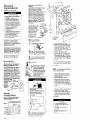
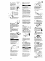
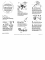
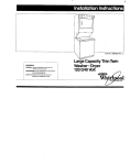
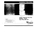
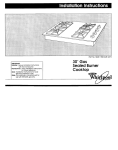
Par? No. 76724.CO/4320880
IMPORTANT:
Maller:
Leave Installation Instructions
with the homeowner
Homeowner:
Keep Installation Instructions
for future reference.
Save Installation Instructions for local electrical
inspector’s use.
30” Freestanding
Gas Range
Before you start...
Proper ln~lollol~on
IS your resporwbrlrty
Makn sure you have everything
“ecessory
lor correcl
~nslollol~on
II IS the responsrbrlriy
of the rnsloller lo comply
wrlh the ~nslollat~on
cleoronce
specrlred
on the senalirairng
plate
The serroliralrng
plate co” be
found under the cooktop
III/l
I
JI
Check
locahon
where range WIII
be rnslalled
The locol10”
should
be away lrom strong droti Oreos.
such OS windows.
doors. and
strong heatrng
vents Or fans The
range should be localed
for
convenient
us R rn the krlchen
,4”+ir.mS I muS,
Recessed
~nsl~,,~,,~.
provide
complele
en closure of
me s,‘4-e ,.-A 1^^1 -I
!
ALL OPENINGS
IN THC WALL
OR FLOOR WHERE THE RANGE
IS TO BE INSTALLED MUST BE
SEALED
Fire Hazard
a Do Not use or store gasoline.
point
thinners ond other flammable
malerlals
near range
. Do Not obstruct the flow of
combuslion
and ventilation
air.
. If you smell gas:
I, Open windows.
2. Don’1 touch electrical
switches.
3. Extinguish any open flame
A. Immediately
call your gas supplier.
Failure to follow these instructions
could
rest.111in fire or explosion.
Note Clearances
specrlred
ore for combustrble
walls ond
moterrols
that hove o density of
II!
, i~~~h~t
I
llh or C~bl”dS
,bcwe the range
Personal Injury Hozord
Avoid inslolling
cabinel
storage above
the cooking
surface.
If cobinels
ore
already
inslolled.
reduce the hazard
of reaching
over o healed cooking
sulloce by rnslalling
(1 range hoad. The
range hood should extend o minimum
of 5 inches out lrom Ihe bottom front of
Ihe cabinets.
Reaching
over o healed cooking
surface could resull in o serious burn
and personal injury
Cabinet
opening
dimensions
lhot ore shown must be used
Given drmensrons
provrde
Eleclr~col Shock Hazard
II is the customer’s
responsibility:
. To conlacl
CI quaIlfred electrrcal
Installer.
- To assure lhal the electrical
installation
is odeauate
ond in
conlormance
wilh’Nalionol
Electrical
Code, ANSI/NFPA 70 lutes.1 edition”.
and a11 local codes and ordinances.
connection
See Gas Supply
Failure to do so could result in fire,
electrical
shock or other personal injuv.
Mobile
4,
I
Home
Installation
The rnstallatron
of thus range must conform
to the Monufoclured
Home Constructron
and Safety Standards.
Trtle 24 CFR. Part
3280 (formerly the Federal Standard
for
Mobrle Home Conshuct~ons
and Safeby.
Trtle ‘24, HUD Port 280)
When mis range is lnslalled I” o mobile
home. it must be secured to me floor
durrng transit
Any method
of securing the
range is adequate
os long os It conforms
to the standards
lrsted ObOVe.
Copies of the standard
listed above
be obtalned
horn:
‘American
Gas Association
1515 Wilwn Boulevard
Arlinglon.
Virginia
22209
Important:
Observe
011 governing
codes ond ordinances.
Tools needed
for installation.
hard or &cMc
drll,
“Notional
Fire Proteclion
Batterymarch
Park
Quincy.
Massachusetts
may
Associolion
02269
wood ftoorr: 1/1’drt,, bll
Concrete/cerarr&z
“oor: 1/A’ masenry dr,,, b,,
up to ‘2.m feet. For elevottorx
above
2aM) feet. ratings should be reduced
at o rote of A% for each l.CrX feel
above sea level.
Gas supply
requirements
Observe all governing
and ordinances.
codes
Fire Hazard
. Range must be connecled
to a
regulated
gas supply.
. LP. gm supply must Not exceed q
prassure of Id’ water column
This
must be checked
by a quolilied
lechnician
before lnslalling
the wen
- Do Not use an open flame to tesl
for leaks from gos connections.
- New, flexible gas line must be ured.
Failure lo follow these rnslructions
could result in a fire, explosion
or
personal injury
This rnstollotion
must conform with
A
. local codes ond ordina”ces.
In
me obs?“Ce Of IoCoI CO&S. l”StOllOtlO”
must conform with Amerkon
Nonow
Standard.
National
Fuel Gas Code ANSI
2223.1 - latest edition.’
C
This range Is equipped
for use
. with NATURAL QOS. It ISdesigncerttned byA.G A. fof NATURAL and L.P
gases with appropriate
conversion.
The
serlallrating
plate located
under me
ccektop
has lnformonon
on me type of
gas that can be used. If this information
does not agree with the type of gos
available.
check with the local gas
supplier.
See bock cover for L.P. gas
conversro”
instructions.
Thii’voive
should be located
In the zume
room OS the rorwe and should be In o
location
that all&s
ease of opening
and
closing.
Do rwt block access to shutoff
valve.
All strains must be removed
from the
supply and fuel lines so range
will be level and in line.
Provide o gas supply line of 314’
n
rrgrd prpe to the range location.
Pipeioint
compounds
resistant to me
action of L.P. gos must be used. Wrth L.P.
gas. piping or tubing srze co” be 112
mlnlmum.
L.P gas suppliers usuoIIy
deterrrrne
the size and materials
used
on their system
The Inlet pressure to the regulator
H
. should be os follows for both
operation
and checking
regulator
setting:
NATURAL GAS:
Minimum
pressure 6 inches
Maximum
pressure IA Inches
L.P. GAS
Minimum
pressure 11 inches
Maximum
pressure 14 inches
(new) is recommended
for connectzng
this range to the gas supply line Do
not kink or damage
the f&able using
when moving the range.
A 112. male
pope thread is needed
for conr~ect~~n to
pressure regulator
female pipe threads
The range and Its lndrvrdual
shutoff
I . valve must be disconnected
from the Qos supply prping system dunng
any pressure lestlng of that system ot test
pressures in excess of 112 PYQ (3 5 kPa).
The range must be rmloted from the gos
supply piping system by closrng Its
IndlVla~~
1nOnUoi 5hUrOff VOW aUrlnQ
any prewre
testi”Q of the Qos supply
prprng system 01 test pressures equo1 to
or less than l/Z ps1g (3 5 kP0)
D
Electrical
requirements
(If model
is so equipped.)
Eleclricol Shock Hozord
- Electrical ground k required on this
appllonce.
- Improper conneckon
01 the
equipment-grounding
conductor
can result in tire, electrical
shock,
or other personal injury.
- Check with o qualitied
electrician
it
You ore in doubt (II lo whether the
appliance
is property grounded.
Do
Not modity the power supply cord
plug. iT it will not fit the outlet. have
o proper outlet inslalled
bY o
qualified
electrician.
. Do Nol use an extension
cord wilh
this applionca.
. Do Not have (1 fuse in the neutral or
grounding
circtil.
A fuse rn the
neutral or grounding
circuit could
result in on electrical
shock:
Failure lo tallow lhese instructions
could result in fire, electrical
shock
or olher personal Injuly.
I-----’
A 1’2OVolt. &Hz. AC-only.
15.Ampere
haed electrical
supply ls required
(Hmedeloy
tise or &cult
breaker Ls
recommended).
It Is recommended
that
a separate
Clrcult serving only Hlls
appliance
be ptovlded,
Electronic !gnit!an systems operate
tithln
wide voltage Ilmlts. but proper arodina
and pokxiti
are necesury:
h addition
G
checking
that the oultet provktes 12Dvdt
power and k correcIiy grounded,
the
otiet
must be checked
by a qwlit?ed
electrkian
to zee II It Ir, correcny wired.
A tiring diagram
b Included
in literature
pcckage.
The wiring diagram
Is alsa
located on the back of the range.
Electrical ground is required on this
oppllance.
II changing
and properly grounding
the
wall receptacle
ir impossible
and where
local codes permit (consult Your
electrkal
inspector).
a tempotory
adaptor
may be plugged
Into the
extstlng 2.prong wall receptacle
to mate
tim me J-prong power y~p@Y cord.
If mls is done.You
must connect
a
saporate
copper grounding
tire (No.-18
mlnlmum)
to a grounded
cold water
pipe”’
by rneanr of a clamp and Men
to me external grounding
connector
screw. Do not ground to a gas supply
pipe or hot water plpe. Do not connect
to electrtcal
supply unti appliance
is
permonentty
grounded.
(see Film
2.)
- . I/..
. ..Gro”“ded
cola water ptpe
must have metcl conti”“ltV
to electrlcoi ground and no,
be lnterrup+ed by ploshc.
rubber or other elec+ricoI
I~lanng
Connectorssuch
OS hoser. hhrngs. Washers or
gaskets (inciudlng water
meter or pump). Any
electrIcal lnsularlng
cmnector
should be
jumped 08 show- with
No.d wire securelv
1
Remove
Numbers
correspond
to steps.
in kitchen.
racks and oltwr
. fromltideoven.
parts
to tree rear legs. Gently lower range to
floor. Tilt range backwards
until front legs
are free
Remove shipplng materials.
tape
. and protective
film horn range.
3
Do not remove cardboard
shipping base
at mis hme.
Recommended
grounding method
DO NOT. UNDER ANY CIRCUMSTANCES.
REMOVE THE POWER SUPPLY CORD
GROUNDING
PRONG.
For Your personal safety. mls appliance
must be grounded.
MS appliance
Is
eaukwed
with a power X&Y
cord
h&l&
a 3pro~~grwndlng
plug. To
mlnlrrdze possible shock hazard. tlw cord
nx6t be plugged
Into a mating J-prong
groundln@ype
wall receptacle,
grcwded
In accordawe
m
the
NaHanal Electrical Code. ANSI/NFPA 70 latest edltlcn”.
and all local codes and
ordlnonces.
(See Flgws 1.) n a maw
wall receptacle
knot cwaUaMe. It Is the
16.
4.
Now start...
With range
5.
To install anti-tip
l Measure
and
ol i% cabinet
Measure and
13.15116’ tram
of me center
Measure and
3/B’ from the
lo Instoll anti-tlp bracket
on 11-r:
a Measure and mark a line at me Center
ol the cabinet
opening
on the Hoor.
Measure and mark lines 12-13/16’ar?d
13.15/16’ from either the lett or rtght side
of me center line on the Roar. Measue
arc mark on me floor a line I’ from the
rear wall.
Note: II ttwe Is a cabinet
on only one side.
the anti-tip bracket
must be Installed rw?.i
to the cabinet,
using measurements
gtven.
The backguard
may already
be assembled
to the range.
g If it Is not. Insert backguard
supports Into holder on the
sides 01 the range.
Press
backguard
down unltl locked
Into place.
Lin cooMop and
insert backguard
electikal
connector
plug Into
receptacle
In rtght rear 01
burner box area
Check that wtrlng Is not klnked of plnched
between
holders and bockguard.
Go to Step 7.
bracket
Alternate
grounding
II Hw range will Not be Installed
. agolnst a cabinet.
the ant+tip
must be Installed.
. Slide range Into final locahon.
Mark a
lhne on the Rooi along each side of
range about onehalf
me distance
from
me rear to the Iront.
To Install anti-ttp
l
method
. To prevent tipping. tnstall range
anti-tip bracket.
- Sow these Instollalion
Inslructions.
II range is moved to a new location.
the or&tip
brackel
must be
removed
and reinslalled
in the
new localion
Do NOT. UNDER ANY CIRCUMSTANCES.
REMOVE THE POWER SUPPLY CORD
GROUNDING
PRONG.
brackel
on wall:
Measure arc mark a lane on H-6 rear
wall at the center of mheran33 location.
Measure and mark lines 12-113/l& and
13.15/16’ horn the lett or right sides of
me center line on the rear wall. Measure
and mark on the rear wall a line 310’ horn
me floor.
lo Install antl-tip
electrklon.
bracket on wall:
mark a line at the center
opening on the rear wall.
mark lines 12.13/16’ and
either the left or right side
line on the rear wall.
mark on Ihe rear wall a line
tloor
brackel
on Iloor:
. Measure and mark o lane on the noor at
the center of the range locatIon.
Meowreond
morkllnes
12.13116’ond
13.15/16’ from the left or rlght’slde of
the center line on me floor. Measure
and mark on the floor a line 1’ horn ti
rear wall.
Go to Step 7.
Floor Damage
- Conloct o qualified
carpet installer
tor the best procedure
to drill
mounling
holes through your type
01 carpet.
- Betore moving range across rIoor.
slide range onto cordbxxd
or
hordboard.
Fo~lure lo totlow lhese instructions
may result in damage
to tloor
CoverIng.
anti-tip bracket
must be installed
Anti-hp
bracket
may be fastened to the floor
under range or wall behmd range
Panel
B
7.
To mount onll-lip
bracket
lo
wood rbor or wall. drill l/8’
hde~ 0t the two mounnng
sc,ew bcatlorls
where me
two lines ore craned
by the
third line.
screvl
loCalions
15
minuie;lor
gas Ilne
To mod
onff-lip brockel
lo
concrete
or ceramk
float or
wall, use o mosoru-y drill
bit to drill l/4’ holes at each
mounting
screw locatIon..
Tap plostlc anchors Into
mounthg
holes In floor
or won.
open tha shutoff valve in the
gas apply line. Wait 0 few
gas to move through tiw
loosen screw and adJust the &r shutter
until the proper time
appears
TiQhten screw. Replace broiler drawer.
Standing
16
bracket
with holes in
n00r 0, ~011. Use me
screws provided
to
mount the anti-tip
bracket
to the floor
or wall.
Move range close to flnol position
Remove the cardboard
or
hardboord
tom under the range. Plug
power supply cord into grounded
outlet.
Remove broiler drawer. Look mder
range (a Ilashllght may be needed)
to
check ttmt anti-tip bracket
overlops range
base
If ontl-tip bracket
does not oveflop
hose. rerr-ove range one reposltlon
bracket
to tmue that range txxe till fit properly
under bracket.
Use o brush and liquid
. detergent
to test all gas
connections
for leaks Bubbles around
connections
will indicate
o leak. If o leak
oppeors. shut oft gos valve controls and
wrench-tighten
connechonr.
hen check
connections
again. NEVER TEST FOR GAS
LEAKS WfTH A MAICH OR OTHER FLAME.
Clean all detergent
soluhon from range.
lnlllal llghllng and gas flame odjuslmenls
depend on type of syslem electronic
Ignition or stondlng pIlot.
Rake cooktoo
and check wtlch svstem Is
available.
Cbntinue
wtollaHon.
fdllowing
stem under the heodlng
for this range’s
system.
Electronic
Ignition
System
Cooktop
and oven burner use elechonlc
igniters In place of standing pilots. When
the cooktop
control knob Is timed to the
‘LITE’ position, the system creates Q
spark to light me burner. Thls sparking
continues
until the control knob is twned
to the desired setttng. When the Oven
contrd
Is fumed on. the spahlng
till
continue
until H-6 oven pilot Ignites. men
the SparkIng stops outOmotlColt$
17
me
Check
OperonOn
. of the cOOktop
burners. Push in and turn
eOch conhol knob to ‘ITIEposition
The flame should
light wittin 4 seconds.
Do not leave the knob in Ihe c3
‘LITE” podlion after burner lights.
the range
in o mobile
the
ran@3 to me Root. Any method of
securing the range Is adequate
os long
(1s it conforms to lhe standards
listed In
the Mobile home Instollofion
Irrst~ctions.
Panel A
12
Place rock in oven.
m Race level on rock.
first side to side. then front to
back. If range Is not level at t
front. adJut front leveling leg
down vltll the rome k level,
range reeds odJu&g.
odust rear leveling
legs up or down until range Is level. If rear
legs ore od]urted
downward
more than
118’. odd shlrm under ant+fip bracket.
‘6
13
Assemble the flexible
.
connector
from the gos supply
pipe to the pressure regulator
In order.
manual shutotf valve. l/2’ nlpple. 112’
adapter,
flexible connector.
1’/2’
adapter.
and l/2’ nipple.
4.
Panel
C
After burner lights. turn control
. knob to ‘HI- position.
Check
each cooktop
burner for proper flame.
The small inner cone should hove o vew
distinct blue flame 114’ t0 112’ long. The
outer cone Is not 0s dtstrnct 0s the inner
19
Fire Hazard
Do Nol make connecllon
loo Ilght
The regulator is die cost.
Over tightening
moy crock Ihe
regulalor.
resulling in (1 gas leak q nd
possiMe fire or explosion.
1
U5-y pipe-joint
com,pwnU
resstont to me actron oft
gas 63 sBoI all gas connections.
If
flexible connectors
are used. be
certain connectors
ore not kinked
P
If burners need adjustrng for
. proper name. adjust me air
shutter to the widest opening
ttwt will
not come me Aame to lift or blow off
me burner.
Repeat 0s necessorJ with
each burner.
Note: Oven must be level for xlfisfactory
boklng conditkx6
P
17A
n
Be sure all control knobs ore In
me ‘OFF. posItion.
Raise the
ccoktop.
--x
Use o match to light both pilots. Adjust
pilot od)ustment
screw so @lot flame tip
is l/4’ to 3/B’ high and centered
in the
hole In the pllot hou%lng. If the fiome is
too high, curbon (soot) will oCCumulote
under me cooktop.
f3
"'- 18Am~~~~~or
me
‘,! cooktop
burners.
Push In and
turn arch control knob to
‘LITE- position.
The fTame should light
wlmin 4 second?.. Do not leave the knob
In the ‘LITE’ poslllon otter burner Ilghls.
llTl
*,
1 1mhome.~ouMUSTsecure
18
If lnstollrng
Pilot Systems
19A
After burner lights. turn
. control knob to ‘HI’
position.
Check each cooktop
burner
for proper Rome. The small Inner
cone should have o very distinct
blue name 114. to l/2’ long. me
outer cone Is not 0s dbtlnct OS
the inner cone
20A
If burners need cd)usting
. toi proper flame. adjust
the olr shutter t0 the widest Opening that
will not cause the name to lltt or blow otf
of me bwner.
Repeat OS necenorv
tim
Make sure the Oven control knob k In
the ‘OFF’ position.
Remove
the lower
oven rack and oven bottom.
Hold Q
lighted match to the opening
In the top
0f me pilot ot me rear 0f the oven burner.
No pilol od]ustments
ore required.
N
ti
oven burner. Push In
and ha-n the oven contfol
knob to 3M)’ F. The oven
burner should lght in 50 to &I seconds.
Thk delay k norm0
The oven safety
valve reqtires 0 certo1n time before It till
open and Qllow QOS to flow.
Producl Damage
Do Not insert any object inlo Ihe
openings 01 lhe proleclive
shield
lhol surrounds the rgniler coil.
Do no, clean Ihe oreo
Fo~lure lo follow these inslruclions
could result in producl damage.
22A
Check
n
operation
the
of
the oven burner.
Push In
or-c hsn me oven control
knob to 3CO’F. The oven burner should
liclht In 50 to 60 ~e~0i-d~.
mk de10~ IS
n%mol.
me oven safety valve rtiulres
a certain ltme before it will open and
allow gas to flow.
23A
Check the oven burner for
proper name. mls flame
should be 712’ long. ‘.+ith inner cone of
bluishgreen.
and outer mantle of dark
blue and should be clean
lifting of Rome
should occur.
21
Check the oven burner for
. proper Aome This name should
be l/2’ long. with rnner cone of bluish
green. an outer mantie of dark blue
and should be clew and soft in
cnaroctor,
No yellw
imps. blowing or
lifting of flame shocld OCCUR
needs to be adjusted,
looen
xlrew and
adlust me air shuner unnl me proper
flame appwrs
Tlghten screw. Replace
broiler drawer.
finished installing your
new Whirlpool ranae. To aet the
most efficient use from your new
range, read your Whirlpool Use&Care
Congratulations!
C
Guide. Keep Installation
Instructions
and Guide close to range for easy
reference.
The instructions will
make reinstalling
your Whirlpool
h
Burners:
Turn the orifices
hood down until snug
against pin. DO NOT OVERTIGHTEN.
Adjust the air shutters for proper flame by
sliding the air shutter to close or open the
shutter as needed.
See Panel C, Step 18
for electricul
lgtition systems or Step 19P
for standing pllot systems.
LX Gas
Conversion
(Electronic
Ignition
Pilot Systems)
Converttng to L.P. gos
should be done by
a quaffled Installer.
’
Oven Burner: Remove oven
racks and lower panel from
oventottom.
Turn the orifice hood
down until snug against pin. DO NOT
OVERTIGHTEN. The burner flame should
be l/2’ long when air shutter is correctly
adjusted
The air shutter slides to close or
open the shutter OS needed.
See Pane
C, Step 21 for electronic
ignition systems,
or Step 23A for standing pilot systems.
Replace oven bottom ond rocks.
and Standing
D
Oven thermostal:
Remove
.
thermostat
knob. pulling straight
off. Use a small screwdriver
to rotate the
key to L.P. Replace thermostat
knob.
Nahml
Caoktop
burners with standing pilots
require adjustment
of pilot flame to l/4’
hlgh. The adjustment
control is located
on the manifold plpe or at pilot ftame
base, depending
on the model,
Only a qualified
installer should
n
Install or
adjust your gas range.
Pressure Regulator:
Use a wrench to
unscrew the COD from
the top by turning counterclockwii.
Turn the cap over so the hole
end is up. Replace the cop and gasket
on the regutator.
DO NOT REMOVE THE
PRESSURE REGULATOR.
A
TKifl
2
Part No. 76724.CQ/4320880
01990 Whirlpool Corporation
Prepared
by Whirlpool
Corporation.
E
After all the burners have been
converted
to L.P. gas usage and
gas~ne is connected,
check for leaks.
Use a brush and liquid detergent
to test
all gas connections
for leaks. Bubbles
around connections
will indicate a
leak. If a leak appears, shut off gas
valve controls and wrench-tighten
connections.
Then check connections
ogoln. NEVER TEST FOR GAS LEAKS WITH
A MATCH OR OTHER FLAME.
01
CORPORAllON
Benton
Harbor.
Michigan
49022
Printed in U.S.A